PNEUMATIC CLUTCH-BRAKE SERIE 58
|
|
|
- Teresa Burns
- 5 years ago
- Views:
Transcription
1 MOUNTING & MAINTENANCE INSTRUCTIONS PNEUMATIC CLUTCH-BRAKE SERIE 58 PLEASE READ THIS MANUAL VERY CAREFULLY BEFORE SETTING UP THE CLUTCH-BRAKE UNIT GOIZPER S. COOP. Antigua, Antzuola (Guipúzcoa) SPAIN Bergara Fax: goizper@goizper.com
2 CONTENTS 1. GENERAL ASPECTS APPLICATION WHO IS THIS MANUAL ADDRESSED TO? IDENTIFICATION OF THE UNIT GENERAL FEATURES ASSEMBLY OF THE CLUTCH-BRAKE IN THE MACHINE UNPACKING THE UNIT AIR SUPPLY ASSEMBLY OF THE CLUTCH-BRAKE TO THE SHAFT With keyway With locking ring ASSEMBLY OF THE CLUTCH AND BRAKE DISCS Fixed disc with friction blocks Sliding disc over 12 fixed bushes Sliding disc with 2 anchor pins Combined assembly SET UP MAINTENANCE PERIODICAL CHECKS CONTROL AND ADJUSTING OF THE WEAR DISASSEMBLY AND ASSEMBLY OF THE CLUTCH AND BRAKE DISCS Disassembly Assembly DISASSEMBLY AND ASSEMBLY OF THE CLUTCH-BRAKE Disassembly Assembly SPARE PARTS REPAIRS: CAUSES AND SOLUTIONS... 23
3 1. GENERAL ASPECTS 1.1 Application This kind of pneumatically actuated combined clutch-brake is mainly used in mechanical presses and other applications where it is necessary to transmit torque and accelerate important masses, and when the characteristics match together with the ones required in the 5.2 paragraph of the EN 692 norm, fulfilling its requirement. This clutch-brake is designed for its dry performance. Due to the high potential technical loads involved, it is very important to calculate the application depending on parameters such as inertia to accelerate and decelerate, speed, frequency of operation, torques, working pressure and ambient temperature. Therefore it is very important to fulfil the conditions that the clutch-brake has been calculated for. GOIZPER S. COOP is not responsible for the eventual personal or material damage that may arise from the unforeseen use of the clutch-brake nor for the modifications introduced in the unit without express authorisation or the non fulfilment of the indications subject of this manual. Besides the indications of this manual, safety regulations must be satisfied according to the working areas. 1.2 Who is this manual addressed to? This manual should be read and understood before the installation and set up of the clutch-brake by: Qualified personnel responsible for the machine Qualified personnel responsible for the mounting of the machine Qualified personnel responsible for maintenance It is important that this manual is at the disposal of the a/r personnel. If there is any doubt, please contact Goizper S. Coop.
4 1.3 Identification of the unit The clutch-brakes are provided with an identification plate, where all the necessary data regarding the unit is indicated (except for sizes 23 and 50 that have this information marked on the outside). Code Service Pressure (bar) Clutch Torque (Nm) Brake Torque (Nm) Our order number For the correct application of the information in this manual, it is necessary to identify the size of the unit that is defined with the 4th and 5 th digit of the code: Serie Kind of mounting Clutch-brake size WD We can also identify the size of the clutch-brake from its dimensions (Fig 1): B: Outer diameter of the clutch-brake (mm) G: Width of the clutch-brake (mm) Size B G Fig. 1
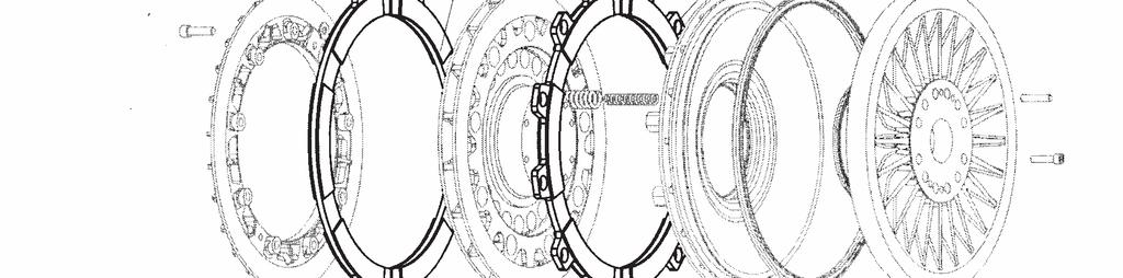
5 2. GENERAL FEATURES BRAKE CLUTCH The clutch-brake consists of mainly 3 parts: a) Clutch disc with bonded linings (E), driven by F E the flywheel and moves axially. b) Brake disc with linings (F), connected to the machine frame, and can move axially. c) Clutch/brake assembly is connected to the A shaft. The clutch plate (2) and brake plate are 6 fixed by screws (9) and connected to the 5 shaft. The brake ring (4) and the piston (3) are also fixed by screws (12) and can move 1 2 axially. 9 Fig. 2 Clutch engagement: Compressed air enters chamber (A) causing piston(3)+brake ring(4) assembly to release from brake disc (F) and engage clutch disc (E) against centre brake plate (1). Flywheel rotation is transmitted to the clutch-brake and shaft. Brake engagement: Compressed air exhausts from chamber (A), brake springs (5 and 6) act against piston (3) + brake ring (4) assembly, disengaging the clutch disc (E). Assembly (3) + (4) engages brake disc (F) with brake plate (1). Clutch/brake and shaft are brought to rest. Friction pads are for dry operation and therefore it is important to avoid humidity and keep the friction surfaces free from oil and grease. Due to the high thermal energy generated, the clutch-brake should be installed in a ventilated surrounding. The normal service pressure is 5.5 bar, and maximum should be 6 bar. Clutch-side elements could be broken at higher pressure
6 3. ASSEMBLY OF THE CLUTCH-BRAKE IN THE MACHINE 3.1 Unpacking the unit The assembly/disassembly of the clutch-brake should be carried out by qualified personnel, taking into consideration the security procedures. The clutch-brake has some threaded holes making it easier to take the clutch-brake out from the box (Unit Point 2). When cleaning the unit take into account that friction surfaces should be free from oil and grease. 3.2 Air supply Air feeding scheme: 1) Filter 2) Hand reducer 3) Lubricator 4) Reservoir Tank 5) Solenoid valve 6) Rotary union 7) Clutch-brake Fig. 3 The air supply should be dry, filtered and lubricated (1 or 2 drops of oil by m 3 of air) and properly connected. The rotary seal should be mounted concentric with regard to the clutch-brake and without air leakage. It should be connected to the installation with a flexible hose/pipe, in order to avoid tension. It is important to connect the solenoid valve as near as possible to the clutch-brake in order to avoid a delay in the response time. Elements of the pneumatic installation should be sized according to the needs of the clutch-brake, to avoid a delay in the response time. During operation, service pressure should not go below 90% from the nominal pressure. For high operating frequencies, a reservoir tank, correctly sized, should be be used (V DC ). V DC = 4 p V V DC : Volume of the reservoir tank (litres) p : Nominal working pressure (bar) V : Volume of the chamber with maximum wear + vol. tubes to the electrovalve (litres)
7 3.3 Assembly of the clutch-brake to the shaft With keyway Mounting the unit to the shaft should be carried out with two keyways at 180º. Clutch-brake has two air inlets (K) at 180º and at 90º from the keyways (Fig. 4). In order to avoid air leakage the customer will mount the discs (C) to the clutch-brake with a lateral o-ring and another C K o-ring in the shaft (these o-rings are not supplied by us). C Fig With locking ring Clutch-brake has two air inlets at 180º and an air distribution channel between two o-rings (Fig. 5) (supply of the o-rings and locking ring under request). Avoid rough edges to protect the o-rings, by machining the shaft diameter at the air inlet (D1). Prepare a chamfer on the end of the shaft (D2) to avoid damaging the o-rings during assembly. Tighten the bolts of the locking ring to the correct torque, by using a dinamometric key. It is very important to keep the tightening D2 torque indicated by GOIZPER S. COOP. An excess in the tightening can result negatively on the resistance of the clutch/brake and an insufficient tightening D1 could carry out a slide within the shaft. Fig. 5 For the assembly of the ring please follow up the instruction of the manufacturer. The usual process is the following: 1. Clean the contact surfaces and cover with a light oil cover (do not use any oil that might contain molybdenum disulfure). 2. Tighten opposite and uniformly the bolts 2-3 times until the indicated tightening torque indicated by GOIZPER S. COOP is reached. 3. Tighten all the bolts to the torque indicated by GOIZPER S. COP., and according to the instructions indicated by the locking ring manufacturer.
8 3.4 Assembly of the clutch and brake discs. There are many assembly possibilities depending on the type of clutch and brake disc Fixed disc with friction blocks Each disc is fixed by 12 bolts (Minimum quality 10.9) at 30º among each one. The blocks slide in their holes. F E 44 H Fig. 6 Assembly (Fig. 6): 1. Take out the two clutch side discs (E). 2. Mount the clutch-brake on the shaft and in its correct position. 3. Hold temporarily the 2 brake discs (F) to avoid them falling 4. Introduce air to engage the clutch discs. 5. The brake bores and the cover bores must match. Tighten the bolts at the indicated torque and apply LOCTITE (270 or similar). Size Bolt 10.9 M5 M6 M8 M10 M14 M14 M16 M20 M24 M24 Tightening torque Nm Table 1 6. Release the air to engage the brake discs. 7. Mount the clutch disc with their blocks (44). 8. Turn the flywheel so that its threaded mounting holes match the clutch disc holes allowing a gap (H) between the discs. Tighten the bolts to the torque indicated in Table 1. Use LOCTITE (270 or similar). 9. Proceed accordingly with the second disc.
9 3.4.2 Sliding disc over 12 fixed bushes Each friction disc slides over 12 equally spaced bushes. Place in line with the frame or flywheel and fixed by bolts. F E 27 Form A 28 View B 29 View A Form B Fig. 7 Assembly (Fig. 7): 1. When the friction discs are supplied as per Form B, disassemble and take out the clutchside discs (when form A, it is not necessary to do so). 2. Assemble the clutch-brake to the shaft and fix into its correct position. 3. Hold temporarily the brake side discs(f) to avoid them falling. 4. Introduce air to engage the clutch discs. 5. Match the brake disc mounting holes with the holes in the fixed frame. Tighten the bushes (27) and the bolts (28) at the torque indicated in Table 2 by using LOCTITE (270 or similar). Size Bolt 8.8 M5 M6 M8 M10 M14 M14 M16 M20 M24 M24 Tightening torque Nm Table 2 6. Release the air to engage the brake discs. 7. If the clutch discs have become loose mount them again with the adjusting plates (29), with their corresponding bolts and pins and apply LOCTITE(270 or similar). The clutch discs have to match each other using adjusting plates that are supplied with pins and bolts. If they are not mounted in this way, they will not slide due to centrifugal forces. 8. Turn the flywheel so that its threaded mounting holes match the clutch disc holes. Tighten the bushes and bolts to the torques indicated in Table 2. Use LOCTITE (270 or similar). 9. Check that the discs slide axially freely
10 3.4.3 Sliding disc with 2 anchor pins Both half-discs match each other by two lugs (short or long), provided with bushes that slide on pins fixed in the machine frame or the flywheel / /21 F 16 E Fig. 8 Assembly (Fig. 8): 1. Mount the pins in the machine (it is recommended H7/k6), fixed them by the adjusting plate (22) and tighten the bolts (23) by using LOCTITE (270 or similar). One of the pins has 2 parallel flats allowing radial compensation. In the assembly, these flats have to be completely parallel to the clutch-brake radius from the centre of the pin. 2. Disassemble the lugs from the discs and take out the clutch side discs. 3. Put the bushes (14/15) on the corresponding pins (20/21). 4. Mount the clutch-brake on the shaft and fix it in its correct position. 5. Hold temporarily the brake discs (F) to avoid them falling. 6. Introduce air to engage the clutch discs. 7. Fix the brake discs to the lugs with the pins, bolts (16) and nuts with elastic washer supplied. Tighten the bolts to their tightening torque Table 3 using LOCTITE (270 or similar). The bolts must be mounted with their head on the inside, but the lugs must be mounted from the outside of the discs. Size Tightening torque(*) Nm (*) Quality of the bolt 8.8 Table 3 8. Release the air, leaving the unit in brake operation. 9. Repeat point 7 with the clutch side discs (E). 10. Check that the discs slide axially without effort Remarks: If it is possible, assemble the unit without disassembling the lugs from the discs but do not forget to tighten the bolts (16) to their recommended tightening torque as per Table 3 and by applying LOCTITE (270 or similar).
11 3.4.4 Combined assembly A clutch brake can be delivered by combining the described mountings. For its assembly, the instructions in each paragraph should be followed. When sliding discs are concerned, please check that after the assembly the discs slide axially freely 3.5 Set up Stop the machine, disconnect and connect the air a few times, and check that the piston (3) brake ring (4) (Fig. 2) moves correctly. Once the mobile elements of the machine (turn of the wheel, movement of the carriage etc.) are properly adjusted and mounted, set up the clutch-brake. When the discs or the friction parts of the clutch-brake are new, the nominal transmissible torque can be reduced considerably. The nominal torque is reached after an appropriate working period (3 4 hours to hours depending on conditions), taking into account that the maximum cycling frequency indicated for the clutch-brake should not be exceeded.
12 4. MAINTENANCE The assembly/disassembly operations and the necessary adjustments should be carried out by qualified personnel taking the necessary security measurements. Ensure that the machine has stopped and cannot be started. In the event of similar machines or presses, be sure that the flywheel is at BDC (Bottom Dead Center) secured with chocks. In any case, please follow the instructions of the manufacturer of the machine. Precautionary measures should be used as a complement to the security prescriptions and advice included in: Health and Safety regulations and factory and section norms. Laws and national regulations. 4.1 Periodical checks Check the wear of the friction elements, measuring periodically the piston travel (see Chapter 4.2 for measuring the wear). The replacement of the friction discs has to be done with parts supplied by the original manufacturer and following the given instructions (Chapter 4.3). When changing the friction discs, please check that the clutch-brake fixing hole/pins are in good conditions. Revise the situation of the rest of components of the clutch-brake (bolts, etc.). Check that during operation, the temperature of the clutch-brake metal parts does not exceed 110ºC. Control the correct performance of the air supply avoiding leaks and providing an appropriate pressure and lubrication (1 or 2 drops of oil each air m 3 ). If there is an unusual variation of the braking or clutching time, or any other anomaly, stop the machine immediately and request technical assistance. Make the necessary revisions as per the manufacturer of the machine, considering the clutchbrake as a part of the machine. A complete revision of the clutch-brake should be done every 3 million cycles or every 2 years. Clean in particular the friction surfaces, brake springs, seals, bolts and others, and if necessary replace them with original spares from the manufacturer (see Chapter 4.4 for assembly/disassembly of the clutch-brake).
13 4.2 Control and adjusting of the wear Check for wear at 3 points at 120º and with the unit in braking position: Measure the S gap (Fig. 9) existing between the brake side cover (1) and the clutch disc (E), when the clutch disc is moved against the piston (3). Or, measure the travel of the piston (3)-brake ring (4) assembly (Fig. 9). E 4 S Marks of position Fig. 9 The discs or pads should be changed when wear S has reached the maximum admissible values indicated in Table 4. Size New S mm Max. S mm Table 4 The discs should also be replaced when, without reaching these maximum wear values, the thickness of the friction on each of the sides of the cluth or brake discs is 1 mm or less(fig. 10). Fig. 10 This change should be done with the material of the original supplier and as per instruction written in Chapter 4.3.
14 The increase in wear causes bigger braking angles and longer braking times. In order to avoid this effect, it is possible to adjust the wear, by removing or decreasing the thickness of the compensation washers (11) (Table 5). Size Thickness of the mm new washer Table 5 In order to make the adjustment for wear, stop the machine after taking the security measures indicated in the beginning of Chapter 4, proceed as follows: 1. Introduce air to engage the clutch discs. 2. Loosen the bolts (12) of the brake discs. 3. Take out the brake discs (4) and remove the compensation washers (11). 4. Replace the brake in the same position, in order to avoid unbalancing and match the marks 0 in position. Tighten the bolts (12) in a cross pattern, apply tightening torque, as per Table 6. Use LOCTITE (270 or similar). Size Bolt 12.9 M5 M6 M8 M10 M12 M14 M16 M18 M20 M24 Tightening torque Nm Table 6: Brake bolts (12) 5. Check that the S air gap is not less than indicated new S in table 4. Having removed the compensation washers, take into account that the maximum wear admissible before replacing the half discs or pads decreases, and new values are indicated in Table 7 as S max without washer: Size Max S without washer mm Table 7 Remarks: When replacing the clutch and brake discs with new ones, DO NOT FORGET TO REPLACE THE COMPENSATION WASHERS.
15 4.3 Disassembly and assembly of the clutch and brake discs This chapter describes the disassembly and assembly of the clutch and brake discs for their replacement. Chapter 3.4 explains in more detail the assembly process Disassembly Disassemble the clutch discs and then the brake discs. Clutch side discs: Release the air and egage the brake discs. Assembly with blocks: Loosen the bolts and take out the clutch disc Assembly with 12 bushings: Loosen the 12 bolts and the adjusting plates of the clutch-side discs. Take out the bolts and bushings by removing to the centre of the clutch brake and take out the clutch-side discs. Assembly with 2 pins: Remove the bolts connecting the lugs to the clutch discs. Then, take out towards the clutch side. Brake side discs: Introduce the air to engage the clutch discs. Take out the brake discs following the procedure indicated for clutch-side discs Assembly Proceed in the reverse way, assemble first the clutch side discs and then the brake side discs. Do not forget to tighten the bolts to the appropriate torque, using LOCTITE and assemble all the pieces correctly (Chapter 3.4). Please check that after assembly the discs slide axially without any effort.
16 4.4 Disassembly and assembly of the clutch-brake Disassembly E F 4 Marks and position N M Fig Disassemble the brake (F) and clutch (E) discs (Fig. 11) as explained in Chapter Remove the clutch-brake from the shaft, by using the 2 threaded extraction holes at 180º (Table 8). Size Bore M5 M6 M8 M10 M12 M12 M16 M16 M16 M18 φy1 mm φy2 mm Table 8 3. Put the clutch-brake on face M (Fig. 11) of the brake side cover (2). 4. Loosen all the bolts (12) and take out the braking ring (4) and washers (11). 5. Turn the clutch-brake and mount it in face N of the brake side cover (1). 6. Loosen the bolts (9) in cross patten. This way both covers will separate and the springs will gradually loose their expansion force. Take into account that due to the compression of the springs there is a powerful expansion force. 7. The rest of the pieces of the clutch-brake can be dismounted now.
17 4.4.2 Assembly 1. Before mounting, clean the pieces, especially the ones in contact areas, such as sealing faces. 2. Put the brake side cover (1) on face N (Fig. 11). 3. Distribute the springs uniformly (5 and 6) in brake side cover. 4. Put molybdenum disulphide grease (MOLYKOTE BR2Plus or similar) in the brake side cover part where the seal has to be placed. 5. Put the seals (7 and 8) correctly in the piston (3). 6. Mount the piston (3) with the brake side cover (1) matching the marks in position Put molybdenum disulphide grease (MOLYKOTE BR2Plus or similar) in the clutch side cover part where the seal has to be placed. 8. Apply loctite (510 or similar) in the union surface of the brake side cover (1), ensuring an airtight seal. 9. Put the clutch side cover (2) on the brake side cover (1) and piston (3) and match their slots with the air inlet bores and marks position Fix with pins and tighten bolts in a cross pattern (9) to their corresponding torque as per table 9. Use LOCTITE (270 or similar). Size Bolts 12.9 M5 M6 M8 M10 M12 M12 M14 M16 M18 M20 Tightening torque Nm Table 9: Clutch side cover bolts (9) 11. Turn the clutch-brake and lean on side M on the clutch side cover (2). 12. Insert the adjusting washers (11). 13. Mount the brake ring (4) matching the marks position 0 and centre diametrically in order to avoid unbalance.tighten the bolts (12) to their corresponding torque table 10, and fix with LOCTITE (270 or similar). Size Bolt 12.9 M5 M6 M8 M10 M12 M14 M16 M18 M20 M24 Tightening torque Nm Table 10: Brake ring bolts (12)

18 5. SPARE PARTS Replace the pieces with the materials supplied by the original manufacturer only. In order to ask for the spare parts, please follow the instructions listed below: Indicate the code and manufacturing number of the clutch-brake unit, indicated in the plate (sizes 23 and 50 have these data stamped in the unit) (Chapter 1.3). Identify the spare part as per the following figures and tables. Serie: 5.8 Main pieces N. Denomination 1 Brake side cover 2 Clutch side cover 3 Piston 4 Brake ring 5 Outer spring 6 Inner spring 7 Interior seal 8 Outer seal 9 DIN bolt 10 DIN 7979 pin 11 Adjusting washer 12 DIN bolt Perishable material
19 Serie N. Description 581 WD 582 WD 584 WD 585 WD 585 WA 586 WD 13 Disc 14 Short bush holder 15 Compensating short bush holder 16 DIN Bolt 17 Spring washer A DIN Nut DIN Spring dowel pin DIN Bush 21 Compensating bush 22 Plate 23 DIN Bolt 24 Spring washer A DIN Disc 26 Brake side disc (sizes 23 and 78) 27 Bushing 28 DIN 933 / Bolt 29 Adjusting plate 30 DIN Bolt 31 Spring dowel pin DIN Long bush holder 33 Compensating long bush holder 34 DIN bolt 35 Spring washer A DIN Nut DIN Elastic pin DIN Bush 39 Compensating bush 40 Adjusting plate 41 DIN bolt 42 Spring washers A DIN Disc 44 Friction block Fungible material

20 Serie: Serie: 5.81 WD 5.82 WD

21 Serie: Serie: 5.84 WD 5.85 WD

22 Serie: Serie: 5.85 WA 5.86 WD
23 6. REPAIRS: CAUSES AND SOLUTIONS In the following table we indicate the most common problems. If any other problem occurs, please contact the technical assistance service. PROBLEM CAUSE SOLUTION The clutch torque The clutch disc does not slide axially. Check the sliding of the disc on the is insufficient bushes/pins Check the position of the bushes /pins Worn friction elements (discs/pads) Change clutch discs/blocks Oil or grease in friction elements Low or lack of air pressure Eliminate oil or grease and avoid humid ambience Check the air pressure Check if there is air leak from the clutch-brake seals Check the pneumatic installation (valves, etc.) New friction materials. Friction elements Running in (Chapter 3.5) not bedded in Increase of the The brake disc does not slide axially Check the sliding of the disc on the braking angle bushes/pins Check the position of the bushes /pins Worn friction elements (discs/pads) Change clutch discs/blocks Oil or grease in friction elements Eliminate oil or grease and avoid humid ambience New friction materials. Friction elements Running in (Chapter 3.5) not bedded in Fast or unequal wear of the friction material High temperature of the friction surface Check that the S air gap is equal or bigger than the S new indicated in chapter 4.2 Try to have good ventilation surrounding (avoid solid guards) Do not exceed the calculated parameters (speed, inertia, and operations) The clutch or brake disc does not slide Check the sliding of the disc in the axially. bushes/pins Check the position of the bushes /pins
SIT-LOCK self locking elements
 self locking elements Advantages of on the shaft-hub connection compared with traditional systems Easy assembly and disassembly Both actions take place by locking and unlocking the clamping screws with
BoWex FLE-PA. BoWex FLE-PAC. KTR-N Sheet: Edition: EN 1 of BoWex FLE-PA / FLE-PAC Operating/Assembly instructions
 1 of 17 is a torsionally rigid flange coupling. It is able to compensate for shaft misalignment, for example caused by manufacturing inaccuracies, thermal expansion, etc. BoWex FLE-PA BoWex FLE-PAC Drawn:
HYDRAULIC CALLIPER TYPE NHC 900 Instructions for assembly, regulation and maintenance
 Technical data sheet Nº: 53.550 I Edited by: Unitzer Bilbao Tested by: Sales Department Delivery date : May 1.999 Date Rev.5. November 2.005 Date Rev.6. July 2.007 Date Rev.7. October 2007 Aplicación Nuevas
PURPOSE To show the correct procedures for the mounting and use of BREMBO braking systems for racing cars, with cast-iron brake discs.
 PURPOSE To show the correct procedures for the mounting and use of BREMBO braking systems for racing cars, with cast-iron brake discs. RESERVOIR CHOICE OF THE RESERVOIR The capacity of the reservoir must
1 Mounting V-belt drive (motor pulley, fly wheel, V-belts and guard)
") Mounting V-belt drive (motor pulley, fly wheel, V-belts and guard) General safety instructions, requirements and procedures 1 Mounting V-belt drive (motor pulley, fly wheel, V-belts and guard) 1.1 General
Mounting V-belt drive (motor pulley, fly wheel, V-belts and guard) General safety instructions, requirements and procedures 1 Mounting V-belt drive (motor pulley, fly wheel, V-belts and guard) 1.1 General
Multiple disc brakes. pressure released and spring operated multiple disc brakes series LBD T brake. Installation- operating instructions
 Multiple disc brakes pressure released and spring series LBD T brake = 50 Nm - 6300 Nm for dry or wet operation as well as for hardly combustible hydraulic fluids HFA, HFB, HFC and HFD Installation- operating
Shaft Couplings Flange-Couplings Rigid Shaft Couplings Flexible Couplings
 Shaft Couplings Flange-Couplings Rigid Shaft Couplings Flexible Couplings 44 Edition 2013/2014 RINGSPANN Registered Trademark of RINGSPANN GmbH, Bad Homburg 2 Table of Contents Flange-Couplings Page Flange-Couplings
RADEX -N Composite Operating/Assembly instructions
 1 of 14 RADEX -N is a torsionally stiff flexible steel lamina coupling. It is able to compensate for shaft misalignment, for example caused by thermal expansion, etc. note ISO 101. Drawn: 0.05.15 Kb/Wig
Flexible Couplings 44
 Flexible Couplings 44 RINGSPANN Registered Trademark of RINGSPANN GmbH, Bad Homburg MTY (81) 83 54 10 18 Why RINGSPANN Flexible Couplings? No connection of shafts without clutches It is a well-known fact
Installation and Operational Instructions for EAS -Compact overload clutch, Type 49_. 4._ Sizes 4 and 5
 Please read these Operational Instructions carefully and follow them accordingly! Ignoring these Instructions may lead to malfunctions or to clutch failure, resulting in damage to other parts. Contents:
TSCHAN - TORMAX VSG. Installation and Operation Manual TSCHAN Highly flexible shaft coupling BAWE 009-GBR-0 05/2004
 BAWE 009-GBR-0 05/2004 Installation and Operation Manual TSCHAN Highly flexible shaft coupling TSCHAN - TORMAX VSG TSCHAN GmbH Zweibruecker Strasse 104 D-66538 Neunkirchen-Saar Telephone: +49(0) 6821 866
 AUTOGARD SERIES 820 TORQUE LIMITER Installation and Maintenance Manual DB0009 Issue 11 21 Feb 2017 British Autogard Ltd 2 Wilkinson Rd., Love Lane Industrial Estate, Cirencester, Glos., GL7 1YT UK Tel.
 heet: 1 of 22 Backlash-free, torsionally stiff and maintenance-free coupling Type with setscrew Type with clamping hubs Type KN (Taper hubs) Type M with setscrew Type M with clamping hubs Type PI 11-3379-883
2.- HANDLING OF VALVES BEFORE ASSEMBLY 3.- FITTING THE VALVE TO THE REST OF THE ASSEMBLY 5.- PERIODICAL INSPECTION OF THE VALVE AND MAINTENANCE
 Page 1 of 16 CONTENTS 1.- INTRODUCTION 2.- HANDLING OF VALVES BEFORE ASSEMBLY 3.- FITTING THE VALVE TO THE REST OF THE ASSEMBLY 4.- OPERATION OF A BALL VALVE 5.- PERIODICAL INSPECTION OF THE VALVE AND
BUTTERFLY VALVE WITH WELDED ENDS INSTALLATION AND MAINTENANCE MANUAL
 BUTTERFLY VALVE 31300 SERIES INSTRUCTIONS FOR INSTALLATION, USE AND MAINTENANCE 1. Overview Read these instructions carefully before starting the valve installation and start-up work. Safe keep the instructions
Electromagnetic clutch-brake combinations INTORQ
 Electromagnetic clutch-brake combinations INTORQ 14.800 14.867 7.5 120 Nm setting the standard 2 CBC en 5/2005 Contents Clutch-brake combinations Product information 4 Type code 6 Design selection 8 Overview
For advanced drive technology CLAMPEX. Shaft-Hub-Connection. KTR Precision Joints CLAMPEX
 technology CLAMPEX Shaft-Hub-Connection CLAMPEX KTR Precision Joints 07 technology Table of contents Page Brief information 09 Selection and calculation -5 CLAMPEX -Selection Shaft diameter = d 0 10 0
HGS SYSTEM Workshop Manual M103 01
 HGS SYSTEM Workshop Manual M0 0 HGS SYSTEM VERSION.0 EN/0-00 Autobusfabriek BOVA b.v. De Vest 9 5555 XL Valkenswaard The Netherlands Phone: + (0) 40 0846 Fax: + (0) 40 09477 E-mail: basis@bova.nl Website:
Sub Section Title Page No.
 Sub Section Title Page No. 1 Introduction 3 2 Routine Maintenance 3 3 Disassembly 4 3.1 Disassembly of Double Crank Design 4 3.2 Disassembly of Scotch Yoke Design 5 3.3 Disassembly of Actuator Cylinder
Installation and Operational Instructions for ROBATIC -clutch Types _.0 and _.0 Sizes 3 7
 Please read these Installation and Operational Instructions carefully and follow them accordingly! Ignoring these Instructions may lead to malfunction or to clutch failure, resulting in damage to other
Installation and Operating Instruction for Brake Caliper HW 150 HFA and HW 180 HFA E e
 Installation and Operating Instruction for Brake Caliper HW 150 HFA and HW 180 HFA E 09.736e Schaberweg 30-38 Phone +49 6172 275-0 61348 Bad Homburg Fax +49 6172 275-275 Germany www.ringspann.com info@ringspann.com
DB4604 GMR-SD and GMR40-SD Disc Brake Caliper - Spring Applied, Air Released
 DB464 GMR-SD and GMR4-SD Disc Brake Caliper - Spring Applied, Air Released Nominal dimensions given. For specific dimensions please contact Twiflex Limited. For GMR Mk 2 caliper details see DB 364 Air
FHB 8110 Brake Assemblies Installation, Operation and Maintenance Manual Airflex
 FHB 8110 Brake Assemblies Installation, Operation and Maintenance Manual Airflex General Information Forward this manual to the person responsible for Installation, Operation and Maintenance of the product
BURQUIP INTERNATIONAL (PTY) LTD
 LTD") Chapter 6 Transmission The transmission system comprises all of the components that transfer the force and movement from the Braked Coupler to the inertia brakes in the axles. Fit the axles to the trailers
Chapter 6 Transmission The transmission system comprises all of the components that transfer the force and movement from the Braked Coupler to the inertia brakes in the axles. Fit the axles to the trailers
Instruction for RBP250-3 and RBP300-3
 Framo Anti-heeling Pump 1275-0029 -401 Rev.C Instruction for RBP250-3 and RBP300-3 2 of 13 CONTENTS Page 1 General description 2 1.1 Technical data 3 2 Operating information 3 2.1 Prior to initial start
GMR-S and GMR40-S Disc Brake Caliper - Spring Applied, Air Released
 (GMR) 9 (GMR) ø GMR-S and GMR-S Disc Brake Caliper - Spring Applied, Air Released DB Nominal dimensions given. For specific dimensions please contact Twiflex Limited. For GMR Mk caliper details see DB
Installation and Operational Instructions for EAS - HTL housed overload clutch Sizes 01 3 Type 490._24.0
 Please read these Operational Instructions carefully and follow them accordingly! Ignoring these Instructions may lead to malfunctions or to clutch failure, resulting in damage to other parts. Contents:
PNEUMATIC PUMP Series
 PNEUMATIC PUMP Series 3103... User and Maintenance Manual Original text translation TABLE OF CONTENTS 1. INTRODUCTION 2. GENERAL DESCRIPTION 3. PRODUCT-MACHINE IDENTIFICATION 4. TECHNICAL CHARACTERISTICS
TOOLFLEX Operating-/Assembly Instructions
 D-807 Rheine heet: 5810 EN 1 of 19 Backlash-free, torsionally stiff and maintenance-free coupling is a backlash-free, torsionally stiff and maintenance-free metal bellow-type coupling designed to be used
RE / STAR Tolerance Rings STAR Ball Knobs, Knob and Lever Type Handles
 RE 2 970/.99 STAR Tolerance Rings STAR Ball Knobs, Knob and Lever Type Handles STAR Tolerance Rings Product Overview Tolerance rings are made of hard, embossed spring steel strip and belong to the class
Installation and Operating Instructions for EAS -NC clutch Type 45_. _. _ Sizes 02 and 03
 Table of contents: Please read and observe this Operating Instruction carefully! A possible malfunction or failure of the clutch and any damage may be caused by not observing it. Page 1: - Table of contents
SERVO MOTORS BRUSHLESS SERVO MOTORS OPERATING INSTRUCTIONS 2016
 SERVO MOTORS BRUSHLESS SERVO MOTORS OPERATING INSTRUCTIONS 2016 3009/16 en Ed.02.2016 Read these Operating Instructions before performing any transportation, installation, commissioning, maintenance or
Twin Power. Manual. Pneumatic Multiturn actuator in Standard and ATEX design WARNING! WARNING! Mounting. Assembly example
 Top Quality Valve Actuators Made in Sweden Twin Power Manual Pneumatic Multiturn actuator in Standard and ATEX design Mounting The Twin Power actuator works beyond reproach in all positions. Valves with
INSTRUCTION MANUAL INDUSTRIAL PERISTALTIC PUMPS MODEL RBT-70
 INSTRUCTION MANUAL INDUSTRIAL PERISTALTIC PUMPS MODEL RBT-70 This manual forms an integral part of the pump and must accompany it until its demolition. The series FMP peristaltic pump is a machine destined
For advanced drive technology CLAMPEX. Shaft-hub-connection. KTR Precision joints CLAMPEX
 technology CLAMPEX Shaft-hub-connection CLAMPEX KTR Precision joints 227 technology Table of contents Page Brief information 228 Selection and calculation 25-255 CLAMPEX -Selection Shaft diameter = d 0
13. CRANKCASE/CRANKSHAFT/BALANCER/PISTON/CYLINDER
 13. CRANKCASE/CRANKSHAFT/BALANCER/PISTON/CYLINDER COMPONENT LOCATION 13-2 SERVICE INFORMATION 13-3 TROUBLESHOOTING 13-4 CRANKCASE SEPARATION 13-5 CRANKSHAFT 13-7 MAIN JOURNAL BEARING 13-9 CRANKPIN BEARING
Repair Manual and Spare Parts List
 Pneumatic Drive Unit Type Techn. Doc. No. 352 and Accessories for Pipe Cutting Machine Darstellung kann vom Original abweichen Repair Manual and 580027000_Inst_en_Version_02 Repair General In general,
Single-Position Detent Clutch DC Series. (i) MTY (81) MEX (55) QRO (442)
 MTY (81) MEX (55) QRO (442)") Single-Position Detent Clutch DC Series (i) FORM NO. L-2017-A-001 In accordance with Nexen s established policy of constant product improvement, the specifications contained in this manual are subject
Single-Position Detent Clutch DC Series (i) FORM NO. L-2017-A-001 In accordance with Nexen s established policy of constant product improvement, the specifications contained in this manual are subject
70 Series 8700 End Mount Three Phase Brake Instructions IP43 (NEMA 2) Housing
 Housing") Bulletin No. BK4772S-3 (6/2017) 70 Series 8700 End Mount Three Phase Brake Instructions IP43 (NEMA 2) Housing Read carefully before attempting to assemble, install, operate or maintain the product described.
Bulletin No. BK4772S-3 (6/2017) 70 Series 8700 End Mount Three Phase Brake Instructions IP43 (NEMA 2) Housing Read carefully before attempting to assemble, install, operate or maintain the product described.
CLUTCH CONTENTS SERVICE DIAGNOSIS. (a) Worn or damaged disc assembly. (b) Grease or oil on disc facings. (c) Improperly adjusted cover assembly.
 Worn or damaged disc assembly. (b) Grease or oil on disc facings. (c) Improperly adjusted cover assembly.") CLUTCH CONTENTS -GROUP 6 Page CLUTCH HOUSING ALIGNMENT... 6 CLUTCH PEDAL FREE PLAY 1 CLUTCH RELEASE BEARING 5 CLUTCH RELEASE FORK... 5 CLUTCH SERVICING 2 PILOT BUSHING CRANKSHAFT TO TRANSMISSION DRIVE
CLUTCH CONTENTS -GROUP 6 Page CLUTCH HOUSING ALIGNMENT... 6 CLUTCH PEDAL FREE PLAY 1 CLUTCH RELEASE BEARING 5 CLUTCH RELEASE FORK... 5 CLUTCH SERVICING 2 PILOT BUSHING CRANKSHAFT TO TRANSMISSION DRIVE
ROTEX Operating/Assembly instructions Type AFN-SB spec. ROTEX
 0223 EN 1 of 13 Torsionally flexible jaw-type couplings AFN-SB spec. and their combinations for finish bored, pilot bored and unbored couplings 0223 EN 2 of 13 is a torsionally flexible jaw coupling. It
AIR CHAMP PRODUCTS. User Manual. Models DPC-9T and DPC-11T. (i) FORM NO. L C-0501
 FORM NO. L C-0501") AIR CHAMP PRODUCTS User Manual Models DPC-9T and DPC-11T (i) In accordance with Nexen s established policy of constant product improvement, the specifications contained in this manual are subject to change
AIR CHAMP PRODUCTS User Manual Models DPC-9T and DPC-11T (i) In accordance with Nexen s established policy of constant product improvement, the specifications contained in this manual are subject to change
REMOVAL & INSTALLATION
 REMOVAL & INSTALLATION NOTE: For reassembly reference, label all electrical connectors, vacuum hoses and fuel lines before removal. Also place mating marks on engine hood and other major assemblies before
Operating instructions friction couplings ECS and ECSK
 Operating instructions friction couplings ECS and ECSK Contents 1. Assembly drawing 2. Construction and Function 2.1 Construction 2.2 Function 3. Dimensioning of the friction coupling 3.1 Choosing the
VAG CEREX M300 Butterfly Valve
 Operation and Maintenance Instructions VAG CEREX M300 Butterfly Valve KAT 1310-B Edition4 12-17 Table of Contents 1 General 3 1.1 Safety 3 1.2 Proper use 3 1.3 Identification 3 VAG reserves the right to
KEYSTONE. Check valves Figure 85/86 Installation & Maintenance Instructions. Figure 85. Figure 86.
 KEYSTONE Please read these instructions carefully. This symbol indicates important messages and safety instructions. Hazard potentials: disregarding of instructions improper use of product insufficiently
CLAMPEX KTR 603 Operating/Assembly instructions
 1 of 9 The CLAMPEX clamping set is a frictionally engaged, detachable shaft-hub-connection for cylindrical shafts and bores without feather key. Table of contents 1 Technical data 2 2 Advice 6 2.1 General
MULTI CROSS RILLO. Highly flexible tyre coupling with taper bushings
 MULTI CROSS RILLO Highly flexible tyre coupling with taper bushings Maschinenfabrik Dipl.-Ing. Herwarth Reich GmbH Vierhausstr. 53 D-44807 Bochum P.O. Box 10 20 66 D-44720 Bochum Tel.: +49 / (0)234 / 959
Assembly and Maintenance Manual Type ASNU
 Assembly and Maintenance Manual Type ASNU Hatschekstr.36 69126 Heidelberg Germany Tel +49(0)6221 30470 Fax +49(0)6221 304731 info@stieber.de www.stieber.de Date of issue: 30.05.2018 GB Revision: 0 U:\EngUsers\!ProduktDoku\1AAA_Einbauerklaerung_Wartungsanleitung_Konformitaetserklaerung\1AAA_Wartungsanleitungen\Orginal_Worddatei\_ASNU.docx
70 Series 8700 End Mount Three Phase Brake Instructions IP56 (NEMA 4) Housing
 Housing") Bulletin No. BK4773-3 (08/2016) 70 Series 8700 End Mount Three Phase Brake Instructions IP56 (NEMA 4) Housing Read carefully before attempting to assemble, install, operate or maintain the product described.
Bulletin No. BK4773-3 (08/2016) 70 Series 8700 End Mount Three Phase Brake Instructions IP56 (NEMA 4) Housing Read carefully before attempting to assemble, install, operate or maintain the product described.
Z-LOCK INDEX Z2 Z5 Z5/Z6 ZSD ZSD Z-LOCK
 Z-LOCK INDEX TOPIC PAGE INTRODUCTION 1 TYPICAL APPLICATION 2 Z2 MEDIUM DUTY, NON SELF CENTERING 3-4 Z2 MINIMUM HUB DIAMETERS 5 Z2 FITTING INSTRUCTIONS 6 Z5 HEAVY DUTY, SELF CENTERING 7 Z5 MINIMUM HUB DIAMETERS
Shaft Couplings Tru-Line Flange-Couplings Rigid Shaft Couplings Flexible Couplings
 Shaft Couplings Tru-Line Flange-Couplings Rigid Shaft Couplings Flexible Couplings Edition 2015/2016 RINGSPANN Registered Trademark of RINGSPANN GmbH, Bad Homburg Table of Contents Tru-Line Flange-Couplings
Installation and Operating Instructions for ROBA -ES couplings Type 940. _. _ Sizes 14-48
 Table of contents: Please read and observe this Operating Instruction carefully. A possible malfunction or failure of the clutch and damage may be caused by not observing it. Page 1: - Table of contents
CLAMPEX KTR 100 Operating/Assembly instructions
 1 of 9 The CLAMPEX clamping set is a frictionally engaged, detachable shaft-to-shaft connection for cylindrical shafts and bores without feather key. Table of contents 1 Technical data 2 2 Advice 4 2.1
CLUTCH PREPARATION Union Nut Wrench 10 mm Clutch Guide Tool Input Shaft Front Bearing Puller
 CLUTCH CL1 CL2 PREPARATION SST (SPECIAL SERVICE TOOLS) CLUTCH PREPARATION 0902300100 Union Nut Wrench 10 mm Clutch line 0930100110 Clutch Guide Tool 0930335011 Input Shaft Front Bearing Puller 0930430012
Installation and Operational Instructions for ROBATIC -clutch Type and Type Sizes 3 9
 Please read the Operational Instructions carefully and follow them accordingly! Ignoring these Instructions may lead to malfunctions or to clutch failure, resulting in damage to other parts. Contents:
Thomas Disc Couplings Installation and Maintenance Series 52 Sizes with classical disc pack TM (Page 1 of 10) DANGER!
 DANGER!") Thomas Disc Couplings Installation and Maintenance Series 52 Sizes 125-925 with classical disc pack TM (Page 1 of 10) This is the Original Document in English Language Figure 1-1. General Information Thomas
Thomas Disc Couplings Installation and Maintenance Series 52 Sizes 125-925 with classical disc pack TM (Page 1 of 10) This is the Original Document in English Language Figure 1-1. General Information Thomas
CLUTCH Nissan 240SX DESCRIPTION PEDAL HEIGHT & FREE PLAY ADJUST CLUTCH ASSEMBLY R & I Clutch. Pathfinder, Pickup, 240SX, 300ZX
 CLUTCH 1990 Nissan 240SX 1990 Clutch Pathfinder, Pickup, 240SX, 300ZX DESCRIPTION Clutch is of dry, single disc type, with a diaphragm spring type pressure plate. Clutch release bearing is prelubricated.
Installation and Operational Instructions for EAS -smartic synchronous clutch Type 48_. 5._ Sizes 01 2
 Please read these Operational Instructions carefully and follow them accordingly! Ignoring these Instructions may lead to malfunctions or to clutch failure, resulting in damage to other parts. Contents:
Keystone Figure 85/86 Check valves Installation and Maintenance Instructions
 Please read these instructions carefully 1.3 Handling 1.3.1 Packed valves Lifting and handling of the packed valves in crates should be carried out by appropriate lifting equipment. If a fork lift truck
Installation, Operation and Maintenance of Airflex Model AMCB AccuStop TM Clutch\Brake Combination
 AMCB 16200 Forward this manual to the person responsible for Installation, Operation and Maintenance of the product described herein. Without access to this information, faulty Installation, Operation
Keystone Butterfly valves ParaSeal Installation and maintenance instructions
 Before installation these instructions must be fully read and understood Please read these instructions carefully Hazard potentials: disregarding of instructions improper use of product insufficiently
70 Series 8700 Coupler 2-pc Hub & Shaft Three Phase Brake Instructions IP43 & IP56 (NEMA 2 & 4) Housing
 Housing") Bulletin No. BK4775-3 (08/2016) 70 Series 8700 Coupler 2-pc Hub & Shaft Three Phase Brake Instructions IP43 & IP56 (NEMA 2 & 4) Housing Read carefully before attempting to assemble, install, operate or
Bulletin No. BK4775-3 (08/2016) 70 Series 8700 Coupler 2-pc Hub & Shaft Three Phase Brake Instructions IP43 & IP56 (NEMA 2 & 4) Housing Read carefully before attempting to assemble, install, operate or
CH16: Clutches, Brakes, Couplings and Flywheels
 CH16: Clutches, Brakes, Couplings and Flywheels These types of elements are associated with rotation and they have in common the function of dissipating, transferring and/or storing rotational energy.
Installation, Operation, and Maintenance Manual
 Industrial Process Installation, Operation, and Maintenance Manual Series PBV Plastic Lined Ball Valve Table of Contents Table of Contents Introduction and Safety...2 Safety message levels...2 User health
HORSTMAN GREASED LIGHTNING CLUTCH
 HORSTMAN GREASED LIGHTNING CLUTCH Horstman s Greased Lightning (GL) clutch is designed for ultra high performance, and requires expert setup and a serious commitment to maintenance. Warning!!! 1. Clutch
Shaft Couplings. Edition 2015/2016. Tru-Line Flange-Couplings Rigid Shaft Couplings Flexible Couplings
 Shaft Couplings Tru-Line Flange-Couplings Rigid Shaft Couplings Flexible Couplings Edition 2015/2016 RINGSPANN Registered Trademark of RINGSPANN GmbH, Bad Homburg 2 Table of Contents Tru-Line Flange-Couplings
MTMANUAL TRANSMISSION GENERAL 1. SPECIFICATIONS. 1) General Specifications. 2) Tightening Torque MANUAL TRANSMISSION
 General Specifications. 2) Tightening Torque MANUAL TRANSMISSION") 03-3 MT GENERAL 1. SPECIFICATIONS 1) General Specifications 2) Tightening Torque 03-4 OVERVIEW AND OPERATION PROCESS 1. OVERVIEW 4WD Features 1. All gears use the helical type and high strength materials.
03-3 MT GENERAL 1. SPECIFICATIONS 1) General Specifications 2) Tightening Torque 03-4 OVERVIEW AND OPERATION PROCESS 1. OVERVIEW 4WD Features 1. All gears use the helical type and high strength materials.
POMPE AUTOADESCANTI SELF-PRIMING ELECTRO PUMP ACM DISASSEMBLY AND ASSEMBLY INSTRUCTIONS FOR MULTISTAGE SELF-PRIMING PUMPS
 POMPE AUTOADESCANTI SELF-PRIMING ELECTRO PUMP ACM DISASSEMBLY AND ASSEMBLY INSTRUCTIONS FOR MULTISTAGE SELF-PRIMING PUMPS Ed. 02/2011 5 WARNING These instructions are for the maintenance personnel for
Hydraulically actuated clutches and spring-applied brakes clutch/brake combined units
 왎 Hydraulically actuated clutches and spring-applied brakes clutch/brake combined units Or tlinghaus Plates. Clutches. Brakes. Systems. Hydraulically actuated clutches and spring-applied brakes clutch/brake
Electromagnetically actuated clutches and brakes
 Electromagnetically actuated clutches and brakes General notes Dry-running/wet-running 4.03.00 Electrical circuits 4.03.00 Rectifier units 4.03.00 Coil connections 4.04.00 Spark quenching 4.04.00 Protection
Dr. TRETTER AG. Tolerance Rings. safe cost-effective fast assembly
 Dr. TRETTER AG Tolerance Rings safe cost-effective fast assembly Tolerance Rings are corrugated metal strips manufactured of high quality spring steel. Tolerance Rings are a fastening device between two
Service Bulletin No. 1066
 QUALITIES THAT MAKE THE DIFFERENCE Service Bulletin No. 1066 COACH MODEL BULLETIN TYPE : T2100 Series ; C2000 Series : Service information MANUAL & SECTION : Maintenance Manual : Chapter 5 - Brakes Spare
Operating / Assembly Instructions Type A and CS Coupling
 Page: 1 of 14 Subject Index 1. Technical Data 2. Hints 2.1. General Hints 2.2. Warning and Safety Hints. 2.3. General Hints to Danger. 2.4. Proper use. 3. Storage. 4. Assembly. 4.1. Coupling components.
Butterfly valves Figure 56 Installation & Maintenance Instructions
 KEYSTONE Please read these instructions carefully This symbol indicates important messages and safety instructions. Hazard potentials: disregarding of instructions improper use of product insufficiently
CLUTCH COMPONENT LOCATION INDEX
 2005 TRANSMISSION Clutch - MX-5 Miata CLUTCH COMPONENT LOCATION INDEX Fig. 1: Identifying Clutch Components GENERAL PROCEDURES (CLUTCH) PRECAUTION Clutch pipe If any clutch pipe has been disconnected anytime
DelTorq Series 21 ACTUATOR
 Jamieson Equipment Company DelTorq Series 21 ACTUATOR INSTALLATION, OPERATION AND MAINTENANCE MANUAL ENGINEERING DATA SHEET E.D.S. NO EDS055 ISSUE DATE - -- 20/01/2007 (Please read the entire instructions
OLYMPIAN MODEL 740 Operation and Service Manual
 OLYMPIAN MODEL 740 Operation and Service Manual P/N 133911-102 FCI MANUAL P/N 133865-001 Data herein has been verified and validated and believed adequate for the intended use. If the machine or procedures
Maintenance instruction
 Maintenance instruction This maintenance instruction is a step-by-step instruction for service and maintenance on Stafsjö s HG valve. Same procedure also applies for HL, HP and HPT. The instruction shall
Operating Instructions Garlock Butterfly Valves DN : mm / 2-24
 Operating Instructions Garlock Butterfly Valves DN : 50-600 mm / 2-24 PN : 10 / 16 Type: GAR-SEAL SAFETY-SEAL STERILE-SEAL MOBILE-SEAL Conformity declaration... 14 0 Introduction... 15 1 Proper use...
Repair Manual and Spare Parts List
 Hydraulic Drive Unit Type Techn. Doc. No. 362 and Accessories for Pipe Cutting Machine Darstellung kann vom Original abweichen Repair Manual and 580067000_Inst_en_Version_03 Repair General In general,
1994 Mazda MX-5 Miata. CLUTCH 1994 Clutch
 CLUTCH 1994 Clutch DESCRIPTION Miata uses a hydraulically operated clutch. HYDRAULIC SYSTEM BLEEDING 1. Remove bleeder screw cap, located at clutch release cylinder. Install vinyl hose onto bleeder screw.
JC BALL VALVES ASSEMBLY AND MAINTENANCE MANUAL
 JC BALL VALVES ASSEMBLY AND MAINTENANCE MANUAL DOC. MMM1500I SBF AND SBR SERIES (Split body, Semi trunnion, Full and Reduced bore) Figs. 1510, 1516, 1525, 1540, 1515, 1530, 1615 & 1630 FULL BORE PN 10
CLAMPEX KTR 400 Operating/Assembly instructions
 1 of 10 The CLAMPEX clamping set is a frictionally engaged, detachable shaft-to-shaft connection for cylindrical shafts and bores without feather key. Table of contents 1 Technical data 2 2 Advice 2.1
Pressure relief valve
 Pressure relief valve Operating manual Series DHV 712 Version BA-2015.10.20 EN Print-No. 300 510 TR MA DE Rev001 ASV Stübbe GmbH & Co. KG Hollwieser Straße 5 32602 Vlotho Germany Phone: +49 (0) 5733-799-0
Installation, Operation, and Maintenance Manual Full Port Y-Pattern, Bolted Bonnet, Globe and Check Valves
 SMITH VALVES Installation, Operation, and Maintenance Manual Full Port Y-Pattern, Bolted Bonnet, Globe and Check Valves Globe Valve Series: YG80/YG15 Welded Bonnet Globe Valve Series: YG87/YG17 Piston
OVERLOAD CLUTCHES FOR INDEX DRIVES
 The Driving Force in Automation OVERLOAD CLUTCHES FOR INDEX DRIVES WARNING WARNING This is a controlled document. It is your responsibility to deliver this information to the end user of the CAMCO indexer.
ROTEX SD shiftable jaw coupling
 1 of 16 SD shiftable jaw coupling Drawn: 201-08-31 Pz Replacing: dated 2006-08-14 Verified: 201-09-07 Pz Replaced by: 2 of 16 SD is a torsionally flexible jaw coupling shiftable at standstill. It is able
Characteristics of model T-Mec brake
 Characteristics of model T-Mec brake These traditional AC brakes, besides their tested reliability, have the following characteristics: Very strong structure; Quick operating times. They can be considered
1992 Clutch. Eclipse, Expo/Expo LRV, Galant, Mirage, Precis, 3000GT
 Article Text ARTICLE BEGINNING 1992 Clutch Eclipse, Expo/Expo LRV, Galant, Mirage, Precis, 3000GT DESCRIPTION All clutches are single disc type. Pressure plate assembly uses a diaphragm spring to engage
MICHIGAN FLUID POWER
 MICHIGAN FLUID POWER Air Driven Hydraulic Pumps, Power Units and Intensifiers P901 Installation, Use and Maintenance Manual Contents Introduction, Guarantee and Identification Plate Description, Start
MAINTENANCE INSTRUCTIONS
 MAINTENANCE INSTRUCTIONS Direct Mount Pneumatic Actuators Double-Acting and Spring-Return Installation, Service and Operation Sizes 0052 through 0125 COMPONENT LIST Item Description 1 Housing 2 Pinion
Selection Tool. on the Internet at in the section MÄDLER -Tools. Other sizes and designs on request. Connecting Shafts Page 766
 Couplings Overview Friction Clutches Friction Clutches Type B Axial Arrangement Friction Clutches Type C Transversal Flexibility Sliding Hubs with Torsionally-Flexible Coupling Multi-Disk Friction Clutches
BALDOR MN413 Brakes Manual
 BALDOR MN413 Brakes Manual http://www.manuallib.com/baldor/mn413-brakes-manual.html The DODGE D-Series motor brakes are manufactured to NEMA standards for mounting to C-face and double shafted motors.
Highly Flexible Couplings ELPEX-B Series
 Siemens AG 2015 Highly Flexible Couplings ELPEX-B Series /2 Overview /2 Benefits /2 Application /2 Design / Technical data /5 Type EBWN /5 Selection and ordering data /6 Type EBWT /6 Selection and ordering
Nor-Mex G. Assembly and operating instructions TSCHAN Elastic coupling BAWN 002-GBR-1 10/2008
 BAWN 002-GBR-1 10/2008 Assembly and operating instructions TSCHAN Elastic coupling Nor-Mex G TSCHAN GmbH Zweibrücker Straße 104 D-66538 Neunkirchen-Saar Telefon: +49(0) 6821 866 0 Telefax: +49(0) 6821
1.8L & 2.2L 4-CYL Article Text 1998 Subaru Impreza
 1.8L & 2.2L 4-CYL Article Text 1998 Subaru Impreza ARTICLE BEGINNING 1995-98 ENGINES Subaru - 1.8L & 2.2L 4-Cylinder 1995-97: Impreza (1.8L) 1995-98: Impreza (2.2L), Legacy (2.2L) * PLEASE READ THIS FIRST
Flexfence Tension Unit. with Hand Pump. Product Manual. Release 02/16.
 Flexfence Tension Unit with Hand Pump Product Manual www.ingalcivil.com.au 1.0 Safety Precautions 1.1 Personal Protection While operating this equipment it is recommended that the following personal protective
DISASSEMBLY AND ASSEMBLY INSTRUCTIONS FOR LIQUID RING VACUUM PUMPS
 (Rev. 2.0_10-2010) DISASSEMBLY AND ASSEMBLY INSTRUCTIONS FOR LIQUID RING VACUUM PUMPS TRVK 2003 to 5003 TRSK 2005 to 5005 INTRODUCTION These instructions are for the maintenance staff in case of repair
Operating and Maintenance Instructions. Abteilung TB, Schell Seite 1 8 SERIES 56
 Abteilung TB, Schell Seite 1 8 These instructions supersede all earlier instructions, in particular BWS 109-0 till BWS 109-3. For applications in areas with explosion hazard it is obligatory to observe