6-Axis Robots. VT series MANIPULATOR MANUAL
|
|
|
- Dana Ramsey
- 5 years ago
- Views:
Transcription

1 6-Axis Robots VT series MANIPULATOR MANUAL Rev.1 EM18YR3817F
2 MANIPULATOR MANUAL VT series Rev.1
3 6-Axis ROBOT VT series Manipulator Manual Rev.1 Copyright 2018 SEIKO EPSON CORPORATION. All rights reserved. VT Rev.1 i
4 FOREWORD Thank you for purchasing our robot products. This manual contains the information necessary for the correct use of the manipulator. Please carefully read this manual and other related manuals before installing the robot system. Keep this manual handy for easy access at all times. WARRANTY The Manipulator and its optional parts are shipped to our customers only after being subjected to the strictest quality controls, tests, and inspections to certify its compliance with our high performance standards. Product malfunctions resulting from normal handling or operation will be repaired free of charge during the normal warranty period. (Please ask your Regional Sales Office for warranty period information.) However, customers will be charged for repairs in the following cases (even if they occur during the warranty period): 1. Damage or malfunction caused by improper use which is not described in the manual, or careless use. 2. Malfunctions caused by customers unauthorized disassembly. 3. Damage due to improper adjustments or unauthorized repair attempts. 4. Damage caused by natural disasters such as earthquake, flood, etc. Warnings, Cautions, Usage: 1. If the Manipulator or associated equipment is used outside of the usage conditions and product specifications described in the manuals, this warranty is void. 2. If you do not follow the WARNINGS and CAUTIONS in this manual, we cannot be responsible for any malfunction or accident, even if the result is injury or death. 3. We cannot foresee all possible dangers and consequences. Therefore, this manual cannot warn the user of all possible hazards. ii VT Rev.1
5 TRADEMARKS Microsoft, Windows, and Windows logo are either registered trademarks or trademarks of Microsoft Corporation in the United States and/or other countries. Other brand and product names are trademarks or registered trademarks of the respective holders. NOTICE No part of this manual may be copied or reproduced without authorization. The contents of this manual are subject to change without notice. Please notify us if you should find any errors in this manual or if you have any comments regarding its contents. MANUFACTURER VT Rev.1 iii

6 Regarding battery disposal The crossed out wheeled bin label that can be found on your product indicates that this product and incorporated batteries should not be disposed of via the normal household waste stream. To prevent possible harm to the environment or human health please separate this product and its batteries from other waste streams to ensure that it can be recycled in an environmentally sound manner. For more details on available collection facilities please contact your local government office or the retailer where you purchased this product. Use of the chemical symbols Pb, Cd or Hg indicates if these metals are used in the battery. This information only applies to customers in the European Union, according to DIRECTIVE 2006/66/EC OF THE EUROPEAN PARLIAMENT AND OF THE COUNCIL OF 6 September 2006 on batteries and accumulators and waste batteries and accumulators and repealing Directive 91/157/EEC and legislation transposing and implementing it into the various national legal systems. For other countries, please contact your local government to investigate the possibility of recycling your product. The battery removal/replacement procedure is described in the following manuals: VT series manipulator manual Maintenance: 18.4 Replacing the Lithium Battery iv VT Rev.1
7 Before Reading This Manual This section describes what you should know before reading this manual. Structure of Robot System The VT series Manipulators can be used with the following combinations of software. VT6-A901S EPSON RC+ 7.0 Controller Firmware Ver or later Before Ver.7.3.2!!! Ver or later OK OK: Compatible All functions of the EPSON RC+ 7.0 and the robot system are available.!!!: Compatible Connection is OK. It is recommended to use the following versions or later. Display or control may not be operated properly. Shape of Motors The shape of the motors used for the Manipulator that you are using may be different from the shape of the motors described in this manual because of the specifications. Setting by Using Software This manual contains setting procedures by using software. They are marked with the following icon. EPSON RC+ VT Rev.1 v
8 vi VT Rev.1
9 TABLE OF CONTENTS Setup & Operation 1. Safety Conventions Design and Installation Safety Operation Safety Emergency Stop How to Move Arms with the Electromagnetic Brake Arm Motions Release the Brake by the Software Precaution for Operation in Low Power Status Labels Specifications Features of VT series Manipulators Model Number Part Names Outer Dimensions Standard Motion Range System Example Specifications How to Set the Model Environments and Installation Environmental Conditions Base Table Mounting Dimensions Unpacking and Transportation Installation Procedure Power Supply Specifications AC Power Cable Breaker Grounding Connecting the Cables Connection Example Noise Countermeasures Relocation and Storage Precautions for Relocation and Storage Relocation Checking the Basic Orientation VT Rev.1 vii
10 TABLE OF CONTENTS 4. Setting of End Effectors Attaching an End Effector Attaching Cameras and Air Valves Weight and Inertia Settings Weight Setting INERTIA Setting Precautions for Auto Acceleration/Deceleration of Joint # Motion Range Motion Range Setting by Pulse Range (for All Joints) Max. Pulse Range of Joint # Max. Pulse Range of Joint # Max. Pulse Range of Joint # Max. Pulse Range of Joint # Max. Pulse Range of Joint # Max. Pulse Range of Joint # Motion Range Setting by Mechanical Stops Motion Range Setting of Joint # Motion Range Setting of Joint # Motion Range Setting of Joint # Restriction of Manipulator Operation by Joint Angle Combination Coordinate System Changing the Robot Setting the Cartesian (Rectangular) Range in the XY Coordinate System of the Manipulator Operation Mode & LED Overview Switch Operation Mode Program Mode (AUTO) What is Program Mode (AUTO)? Setup from EPSON RC Auto Mode (AUTO) What is Auto mode (AUTO)? Setup from EPSON RC Setup from Control Device LED Development PC Connection Port What is Development PC Connection Port Precaution Software Setup and Connection Check Disconnection of Development PC and Manipulator viii VT Rev.1
11 TABLE OF CONTENTS 8. Memory Port What is Controller Status Storage Function? Before Using Controller Status Storage Function Precautions Adoptable USB Memory Controller Status Storage Function Controller Status Storage Load Data with EPSON RC Transfer with Details of Data LAN (Ethernet Communication) Port What is the LAN (Ethernet Communication) Port IP Address Changing Manipulator IP Address Connection of Development PC and Manipulator with Ethernet Disconnection of Development PC and Manipulator with Ethernet TP Port What is the TP Port? Teach Pendant Connection Options Camera Plate Unit Tool Adapter (ISO flange) Adjustable Mechanical Stops External Wiring Kit EMERGENCY Safeguard Switch and Latch Release Switch Safeguard Switch Latch Release Switch Checking Latch Release Switch Operation Emergency Stop Switch Connection Emergency Stop Switch Checking Emergency Stop Switch Operation Recovery from Emergency Stop Pin Assignments Circuit Diagrams Example 1: External emergency stop switch typical application Example 2: External safety relay typical application VT Rev.1 ix
12 TABLE OF CONTENTS 13. Standard I/O Connector Input Circuit Typical Input Circuit Application Typical Input Circuit Application Pin Assignments of Input Circuit Output Circuit Typical Output Circuit Application Typical Output Circuit Application Pin Assignments of Output Circuit I/O Cable Product Procedure I/O Cable Connecting Method How to Fix the I/O Cable I/O Remote Settings I/O Signal Description Remote Input Signals Remote Output Signals Timing Specifications Precautions for Remote Input Signals Timing Diagram for Operation Execution Sequence Timing Diagram for Program Execution Sequence Timing Diagram for Safety Door Input Sequence Timing Diagram for Emergency Stop Sequence SD Card Slots RESET Switch Fieldbus I/O 111 x VT Rev.1
13 Maintenance TABLE OF CONTENTS 1. Safety Maintenance General Maintenance Maintenance Inspection Schedule for Maintenance Inspection Inspection Point Overhaul (Parts Replacement) Tightening Hexagon Socket Head Cap Bolts Matching Origins Layout of Maintenance Parts Manipulator Structure Alarm Maintenance Maintenance Information How to Check the Maintenance Information How to Edit the Maintenance Information Alarm Notifying Method How to Cancel the Alarm Backup and Restore What is the Backup Controller Function Backup Data Types Backup Restore Firmware Update Updating Firmware Firmware Upgrade Procedure Manipulator Recovery Firmware Initialization Procedure VT Rev.1 7. Covers Arm #1 Cover Arm #2 Cover Arm #3 Cover Arm #4 Cover Arm #4 Cover Power Cable Cover Connector Plate xi
14 TABLE OF CONTENTS 8. Cable Replacing Cable Unit Insert or Pull out of Power Cable Joint # Replacing Joint #1 Motor Replacing Joint #1 Reduction Gear Unit Replacing Joint #1 Timing Belt Joint # Replacing Joint #2 Motor Replacing Joint #2 Reduction Gear Unit Replacing Joint #2 Timing Belt Joint # Replacing Joint #3 Motor Replacing Joint #3 Reduction Gear Unit Replacing Joint #3 Timing Belt Joint # Replacing Joint #4 Motor Replacing Joint #4 Reduction Gear Unit Replacing Joint #4 Timing Belt Joint # Replacing Joint #5 Motor Replacing Joint #5 Reduction Gear Unit Replacing Joint #5 Timing Belt Joint # Replacing Joint #6 Motor Replacing Joint #6 Reduction Gear Unit Replacing Joint #6 Timing Belt AMP Board Replacing AMP Board on Joint #1, #2, and # Replacing AMP Board on Joint # Replacing AMP Board on Joint #5 and # xii VT Rev.1
15 TABLE OF CONTENTS 16. LED Plate Replacing LED Plate Felt Sheet Replacing Joint #2 Felt Sheet Replacing Joint #3 Felt Sheet Controller Unit Replacing Controller Unit Replacing Power Board Replacing CPU/DPB Board Replacing Lithium Battery Replacing Cooling Fan Replacing SD Card Calibration Overview Calibration Procedures Restrictions Commands Cannot Use Commands Cause Motion Error If Specifying RS-232C Commands Cause Error Conveyor Tracking Commands PG Commands R-I/O Commands Force Sensing Commands Other (FineDist) Other (HealthCalcPeriod) Other (ChDisk) Restrictions of Functions TP Loop Processing Camera Searching by CV1/CV Restore the Data of Backup Controller Function Error Code Table Maintenance Parts List 254 Appendix A: Open Source Software License 257 VT Rev.1 xiii
16 TABLE OF CONTENTS xiv VT Rev.1
17 Setup & Operation This volume contains information for setup and operation of the VT series Manipulators. Please read this volume thoroughly before setting up and operating the Manipulators.
18
19 Setup & Operation 1. Safety 1. Safety 1.1 Conventions Installation and transportation of manipulators and robotic equipment shall be performed by qualified personnel and should conform to all national and local codes. Please read this manual and other related manuals before installing the robot system or before connecting cables. Keep this manual handy for easy access at all times. Important safety considerations are indicated throughout the manual by the following symbols. Be sure to read the descriptions shown with each symbol. WARNING WARNING CAUTION This symbol indicates that a danger of possible serious injury or death exists if the associated instructions are not followed properly. This symbol indicates that a danger of possible serious injury or death caused by electric shock exists if the associated instructions are not followed properly. This symbol indicates that a danger of possible harm to people or physical damage to equipment and facilities exists if the associated instructions are not followed properly. VT Rev.1 3
20 Setup & Operation 1. Safety 1.2 Design and Installation Safety Only trained personnel should design and install the robot system. Trained personnel are defined as those who have taken robot system training and maintenance training classes held by the manufacturer, dealer, or local representative company, or those who understand the manuals thoroughly and have the same knowledge and skill level as those who have completed the training courses. To ensure safety, a safeguard must be installed for the robot system. For details on the safeguard, refer to the Installation and Design Precautions in the Safety chapter of the EPSON RC+ User s Guide. The following items are safety precautions for design personnel: Personnel who design and/or construct the robot system with this product must read the Safety chapter in the EPSON RC+ User s Guide to understand the safety requirements before designing and/or constructing the robot system. Designing and/or constructing the robot system without understanding the safety requirements is extremely hazardous, may result in serious bodily injury and/or severe equipment damage to the robot system, and may cause serious safety problems. WARNING The robot system must be used within the environmental conditions described in their respective manuals. This product has been designed and manufactured strictly for use in a normal indoor environment. Using the product in an environment that exceeds the specified environmental conditions may not only shorten the life cycle of the product but may also cause serious safety problems. The robot system must be used within the installation requirements described in the manuals. Using the robot system outside of the installation requirements may not only shorten the life cycle of the product but also cause serious safety problems. Further precautions for installation are mentioned in Setup & Operation: 3. Environments and Installation. Please read this chapter carefully to understand safe installation procedures before installing the robots and robotic equipment. 4 VT Rev.1
21 Setup & Operation 1. Safety 1.3 Operation Safety The following items are safety precautions for qualified Operator personnel: Please carefully read the 1.3 Safety-related Requirements in the Safety chapter of the Safety and Installation manual before operating the robot system. Operating the robot system without understanding the safety requirements is extremely hazardous and may result in serious bodily injury and/or severe equipment damage to the robot system. Do not enter the operating area of the Manipulator while the power to the robot system is turned ON. Entering the operating area with the power ON is extremely hazardous and may cause serious safety problems as the Manipulator may move even if it seems to be stopped. WARNING Before operating the robot system, make sure that no one is inside the safeguarded area. The robot system can be operated in the mode for teaching even when someone is inside the safeguarded area. The motion of the Manipulator is always in restricted (low speed and low power) status to secure the safety of an operator. However, operating the robot system while someone is inside the safeguarded area is extremely hazardous and may result in serious safety problems in case that the Manipulator moves unexpectedly. Immediately press the Emergency Stop switch whenever the Manipulator moves abnormally while the robot system is operated. Continuing the operation while the Manipulator moves abnormally is extremely hazardous and may result in serious bodily injury and/or severe equipment damage to the robot system. WARNING To shut off power to the robot system, disconnect the power plug from the power source. Be sure to connect the AC power cable to a power receptacle. DO NOT connect it directly to a factory power source. Before performing any replacement procedure, turn OFF the robot system and related equipment, and then disconnect the power plug from the power source. Performing any replacement procedure with the power ON is extremely hazardous and may result in electric shock and/or malfunction of the robot system. Do not connect or disconnect the motor connectors while the power to the robot system is turned ON. Connecting or disconnecting the motor connectors with the power ON is extremely hazardous and may result in serious bodily injury as the Manipulator may move abnormally, and also may result in electric shock and/or malfunction of the robot system. VT Rev.1 5
22 Setup & Operation 1. Safety Whenever possible, only one person should operate the robot system. If it is necessary to operate the robot system with more than one person, ensure that all people involved communicate with each other as to what they are doing and take all necessary safety precautions. Each Joint: If the joints are operated repeatedly with the operating angle less than 5 degrees, the Manipulator may get damaged early due to the bearings are not being covered with grease during movement. To prevent early breakdown, move the joints larger than 30 degrees for about five to ten times a day. CAUTION Vibration (resonance) may occur continuously depending on the combination of robot motion speed, Arm orientation, and end effector load. Vibration arises from natural vibration frequency of the Arm and can be controlled by following measures. Changing Manipulator speed Changing the teach points Changing the end effector load Manipulator may be heated due to motor heat etc. Do not touch the Manipulator until temperature falls. After confirming that the temperature of the Manipulator falls and is not hot when you touch it. Then perform teaching or maintenance. 6 VT Rev.1
23 1.4 Emergency Stop Setup & Operation 1. Safety If the Manipulator moves abnormally during operation, immediately press the Emergency Stop switch. Pressing the Emergency Stop switch immediately changes the manipulator to deceleration motion and stops it at the maximum deceleration speed. However, avoid pressing the Emergency Stop switch unnecessarily while the Manipulator is running normally. Pressing the Emergency Stop switch locks the brake and it may cause wear on the friction plate of the brake, resulting in the short life of the brake. Normal brake life cycle: About 2 years (when the brakes are used 100 times/day) To place the system in emergency mode during normal operation, press the Emergency Stop switch when the Manipulator is not moving. Refer to the Setup & Operation: 12. EMERGENCY for instructions on how to wire the Emergency Stop switch circuit. Do not turn OFF the power while the Manipulator is operating. If you attempt to stop the Manipulator in emergency situations such as Safeguard Open, make sure to stop the Manipulator using the Emergency Stop switch. If the Manipulator is stopped by turning OFF the power while it is operating, following problems may occur. Reduction of the life and damage of the reduction gear unit Position gap at the joints In addition, if the manipulator was forced to be turned OFF by blackouts and the like while the Manipulator is operating, make sure to check the following points after power restoration. Whether or not the reduction gear is damaged Whether or not the joints are in their proper positions If there is a position gap, perform calibration by referring to the Maintenance 16. Calibration in this manual. Also, the same troubles may occur if an error occurs and the Manipulator stops in emergency during the operation. Check the Manipulator condition and perform calibration if necessary. Before using the Emergency Stop switch, be aware of the following. - The Emergency Stop (E-STOP) switch should be used to stop the Manipulator only in case of emergencies. - To stop the Manipulator operating the program except in emergency, use Pause (halt) or STOP (program stop) commands Pause and STOP commands do not turn OFF the motors. Therefore, the brake does not function. - For the Safeguard system, do not use the circuit for E-STOP. For details of the Safeguard system, refer to the following manuals. EPSON RC+ User s Guide 2. Safety - Installation and Design Precautions - Safeguard System Safety and Installation 2.5 Connection to EMERGENCY Connector VT Rev.1 7
24 Setup & Operation 1. Safety To check brake problems, refer to the following manuals. Manipulator Manual Maintenance Inspection Point - Inspection While the Power is ON (Manipulator is operating) Safety and Installation Manipulator - Inspection While the Power is ON (Manipulator is operating) Free running distance in emergency The operating Manipulator cannot stop immediately after the Emergency Stop switch is pressed. The free running time/angle/distance of the Manipulator are shown below. However, remember that the values vary depending on following conditions. Weight of the end effector Weight of workpiece Operating pose Weight setting Speed setting Accel setting Conditions for measurement VT series ACCEL Setting 100 SPEED Setting 100 Load [kg] 6 WEIGHT Setting 6 Free running time [sec.] Free running angle [deg.] VT6-A901** Arm #1 0.2 Arm #2 0.3 Arm #3 0.2 Arm #4 0.2 Arm #5 0.2 Arm #6 0.2 Table Top Arm #1 Ceiling 50 Wall 30 Arm #2 70 Arm #3 20 Arm #4 20 Arm #5 20 Arm # VT Rev.1
25 1.5 How to Move Arms with the Electromagnetic Brake Setup & Operation 1. Safety When the electromagnetic brake is operating such as an emergency status, all arms cannot be moved. For procedures to release the electromagnetic brake, refer to the following section. When the electromagnetic brake is released, the arms can be moved by hand Release the Brake by the Software (When the software is available) Arm Motions Upper Arm (Arm #3 to 6) Arm #4 Joint #3 Joint #4 Arm #6 Joint #6 Arm #3 Arm #5 Joint #5 Arm #2 Joint #2 Arm #1 (Lower Arm) Joint #1 Base Joint Motion Joint #1 : The whole Manipulator revolves. Joint #2 : The lower arm swings. Joint #3 : The upper arm swings. Joint #4 : The wrist revolves. Joint #5 : The wrist swings. Joint #6 : The hand rotates. VT Rev.1 9
26 Setup & Operation 1. Safety Release the Brake by the Software Normally, release the brake of joints one by one. Take extra care if you need to release the brakes of two or more joints simultaneously. Releasing the brakes of two or more joints simultaneously may cause hands and fingers to be caught and/or equipment damage or malfunction of the Manipulator as the arms of the Manipulator may move in unexpected directions. CAUTION Be careful of the arm falling when releasing the brake. While the brake is being released, the Manipulator s arm falls by its own weight. The arm falling may cause hands and fingers to be caught and/or may cause equipment damage or malfunction of the Manipulator. Before releasing the brake, be sure to keep the Emergency Stop switch handy so that you can immediately press the Emergency Stop switch. Otherwise, you cannot immediately stop the arm falling due to an erroneous operation. The arm falling may cause equipment damage and/or malfunction of the Manipulator. EPSON RC+ After releasing the Emergency Stop switch, execute the following command in [Command Window]. >Reset >Brake Off,[the arm (#1 to #6) whose brake will be turned off] Execute the following command to turn on the brake again. >Brake On,[the arm (#1 to #6) whose brake will be turned on] 1.6 Precaution for Operation in Low Power Status In the low power status, the Manipulator operates at low speed and low torque. If in close proximity to the Manipulator, operate the Manipulator carefully. Otherwise, your hands or fingers may get caught during operation. The Manipulator may also collide with peripheral equipment and cause equipment damage or malfunction of the Manipulator. CAUTION Carefully operate the Manipulator in the low power status. A comparatively high joint torque may be generated. It may cause your hands and fingers caught and/or cause equipment damage or malfunction of the Manipulator as it may collide with peripheral equipment. 10 VT Rev.1


27 Setup & Operation 1. Safety 1.7 Labels The Manipulator has the following warning labels. The warning labels are attached around the locations where specific dangers exist. Be sure to comply with descriptions and warnings on the labels to operate and maintain the Manipulator safely. Do not tear, damage, or remove the warning labels. Use meticulous care when handling those parts or units to which the following warning labels are attached as well as the nearby areas. Location Warning Label NOTE A Before loosening the base mounting screws, hold the arm and secure it tightly with a band to prevent hands or fingers from being caught in the Manipulator. For transport and install procedures, follow the steps described in this manual. B Do not enter the operation area while the Manipulator is moving. The robot arm may collide against the operator. This is extremely hazardous and may result in serious safety problems. C D Hazardous voltage exists while the Manipulator is ON. To avoid electric shock, do not touch any internal electric parts. When releasing the brakes, be careful of the arm falling due to its own weight. This warning label is attached on the Manipulator and optional brake release box. E Only authorized personnel should perform sling work and operate a crane and a forklift. When these operations are performed by unauthorized personnel, it is extremely hazardous and may result in serious bodily injury and/or severe equipment damage to the robot system. You may get your hand or fingers caught when bringing your hand close to moving parts. F VT Rev.1 11
 label")
28 Setup & Operation 1. Safety Location Warning Label NOTE Signature label S/N (Serial Number) label G Location of labels C F B D E A C C C C C G 12 VT Rev.1
29 Setup & Operation 2. Specifications 2. Specifications 2.1 Features of VT series Manipulators The VT series Manipulators are controller integrated manipulators. The features of the VT series Manipulators are as follows: For Device design and tooling - There is no external controller No installation space required for an external controller. No design is required for external controller installation or tooling. - No robot to controller external cables There are no external cables required between the robot and controller. For Maintenance - There are no motor unit batteries for the robot No longer necessary to connect external devices for battery replacement. - Easy to replace the Manipulator Others - Power-saving VT6L: Approx. 1/5 compared to C4L/RC700-A 2.2 Model Number VT6-A90 1 S Mounting type : Table Top mounting R W : Ceiling mounting : Wall mounting Environment S : Standard model Brake equipment 1 : Brakes on all joints Arm length 90 : 920 mm Payload 6 : 6 kg For details on the specifications, refer to Setup & Operation: 2.7 Specifications. VT Rev.1 13
30 Setup & Operation 2. Specifications 2.3 Part Names Arm #4 Joint #4 LED Lamp (This lamp lights up while the motors are ON.) Arm #6 Joint #6 Arm #3 Arm #5 Joint #5 Joint #3 Arm #2 Joint #2 Arm #1 (Lower Arm) Joint #1 Base EMERGENCY Connector TP Port I/O (Output) Connector I/O (Input) Connector RESET switch MEMORY Port Port of PC for development LAN (Ethernet) Connector OPTION Cover (OPTION connector inside) Power Supply Cover (AC power connector inside) NOTE When the LED lamp is lighting or the controller power is ON, the current is being applied to the manipulator. (The LED lamp may not be seen depending on the Manipulator s posture. Be very careful.) Performing any work with the power ON is extremely hazardous and it may result in electric shock and/or improper function of the robot system. Make sure to turn OFF the controller power before the maintenance work. 14 VT Rev.1
31 Setup & Operation 2. Specifications 2.4 Outer Dimensions VT Rev.1 15
32 Setup & Operation 2. Specifications [Unit: mm] 16 VT Rev.1
33 Setup & Operation 2. Specifications 2.5 Standard Motion Range [Unit: mm] VT Rev.1 17
34 Setup & Operation 2. Specifications * P point : Intersection of the rotation centers for Joint #4, #5, and #6 *1 : P point from top with Joint #3 declining 51 deg (Joint #2 center P point center) *2 : P point from top with Joint #3 tilting up +190 deg (Joint #2 center P point center) *3 : P point from lateral with Joint #3 declining +190 deg (Joint #1 center P point center) *4 : P point from lateral with Joint #3 tilting up 51 deg (Joint #1 center P point center) CAUTION Pay attention to the arm pose of the basic arms (Arms #1, #2, and #3) when operating the Manipulator. Arm #5 moves keeping a constant angle regardless of the arm pose. Depending on the arm pose of the basic arms, the wrist may collide with the Manipulator. The collision may cause equipment damage and/or malfunction of the Manipulator. 18 VT Rev.1
 USB (for development) ModBus VT6 Option Fieldbus Slave USB 2.")
 Windows 10 Pro (EPSON RC+7.")
35 Setup & Operation 2. Specifications 2.6 System Example Standard Standard I/O Remote I/O Ethernet USB (for save) USB (for development) ModBus VT6 Option Fieldbus Slave USB 2.0 or Ethernet *2 Option: Teaching Pendant *3 Windows *1 TP2 EPSON RC+ 7.0 Software Option TP3 *1 EPSON RC+ 7.0 supports the following OS Windows 7 Professional Service Pack 1 Windows 8.1 Pro (EPSON RC+7.0 Ver or later) Windows 10 Pro (EPSON RC+7.0 Ver or later) *2 Either teaching pendant is available. *3 When connecting to VT series manipulators, specified convert cable is necessary. VT Rev.1 19
36 Setup & Operation 2. Specifications 2.7 Specifications Item Specifications Model Number VT6-A901S VT6-A901SR VT6-A901SW Model Name VT6L Mounting type *1 Table Top mounting Ceiling mounting Wall mounting Weight (not include the weight of cables or shipping jigs) 40 kg : 89 lb. Driving method All joints AC servo motor Joint # /s Joint # /s Max. operating speed Joint # /s *2 Joint # /s Joint # /s Joint # /s Maximum synthetic speed 4522 mm/s Repeatability Joint #1 ~ #6 ± 0.1 mm Joint #1 ± 170 ± 30 Joint #2 160 ~ + 65 Max. motion range Joint #3 51 ~ Joint #4 ± 200 Joint #5 ± 125 Joint #6 ± 360 Joint #1 ± ± Joint # ~ Max. pulse range Joint # ~ Joint #4 ± Joint #5 ± Joint #6 ± Joint # /pulse Joint # /pulse Resolution Joint # /pulse Joint # /pulse Joint # /pulse Joint # /pulse Joint #1 300 W Joint #2 300 W Motor power Joint #3 200 W consumption Joint #4 100 W Joint #5 100 W Joint #6 100 W Payload *3 Rated. 3 kg Max. 6 kg Joint #4 12 N m (1.22 kgf m) Allowable moment Joint #5 12 N m (1.22 kgf m) Joint #6 7 N m (0.71 kgf m) Joint #4 0.3 kg m 2 Allowable moment of inertia *4 (GD 2 Joint #5 0.3 kg m 2 /4) Joint #6 0.1 kg m 2 20 VT Rev.1
37 Setup & Operation 2. Specifications Environmental requirements *5 Noise level *6 Environment Default values (Max. setting values) Motion Control External Interface Item Specifications Ambient Temperature 5 ~ 40 C Ambient relative humidity 10 ~ 80 % RH (no condensation) Vibration 4.9 m s 2 (0.5 G) or less L Aeq = 80 db (A) or less Standard Speed (5) 100 Accel *7 (5, 5) 120, 120 SpeedS (50) 2000 AccelS *8 (200) Fine (10000, 10000, 10000, 10000, 10000, 10000) 65535, 65535, 65535, 65535, 65535, Weight 3 (6) Inertia 0.03 (0.1) Development Environment EPSON RC+ 7.0 Programming Language SPEL+ (multi-tasking robot language) Joint Control Standard 6 joints simultaneous control Digital AC servo control Positioning Control PTP (Point-To-Point control) CP (Continuous Path control) PTP motion : Programmable in the range of 1 to 100% Speed Control CP motion : Programmable (Actual value to be manually entered.) PTP motion : Programmable in the range of 1 to 100% Acceleration/ Auto acceleration/deceleration Deceleration CP motion : Programmable Control (Actual value to be manually entered.) EMERGENCY STOP: Redundant (Category 3) Supported for internal/external power EMERGENCY supply Safeguard System: Redundant (Category 3) Supported for external power supply I/O Standard I/O (Rear side of Manipulator) Field bus Slave (Option) Remote I/O (Remote functions are applied to Standard I/O) TP Connection Port PC Connection Port USB Memory Connection Port Ethernet Port RESET Switch Input: 24 points Output: 16 points Non-polar, Supported for both Sink and Source Input: 8 points Program, 3 points Start, Stop, Pause, Continue, Reset Output: 8 points Ready, Running, Paused, ErrorEStopOn, SafeguardOn, SError, Warning Input: 256 points Output: 256 points Enable to add only one more module Supported for teach pendant (Option: TP2, TP3) USB B connector Supported for USB 2.0 High Speed / Full Speed USB A connector Supported for USB 2.0 High Speed / Full Speed Supported for 10/100 Mbps Available up to 8 ports Enable to use for reset of system VT Rev.1 21
38 Setup & Operation 2. Specifications Item Specifications Display Mode Display LED TEACH, AUTO, PROGRAM, TestMode, Error, E-STOP Controller Status Save Save to USB memory Save in RC+ (PC) Voltage 100 ~ 240 VAC Phase Single phase Frequency 50 / 60 Hz Momentary Power Interrupt Less than 10 ms Rating Capacity 1, 200 VA Peak Current (When AC power is turned ON) Max. 60A (Less than 2 ms) Leak Current Max. 10 ma Ground Resistance Less than 100Ω Safety standard CE Mark EMC Directive, Machinery Directive ANSI/RIA R NFPA 79 (2007 Edition) *1: Mounting types other than Table Top mounting, Ceiling mounting, and Wall mounting are out of specification. If you prefer other mounting types, please contact us. *2: In case of PTP control *3: Do not apply the load exceeding the maximum payload. *4: If the center of gravity is at the center of each arm. If the center of gravity is not at the center of each arm, set the eccentric quantity using INERTIA command. *5: For details of the environmental requirements, refer to the Setup & Operation 3.1 Environmental Conditions. *6: Conditions of Manipulator at measurement are as follows: Operating conditions: Under rated load, all arms simultaneous motion, maximum speed, maximum acceleration, VT6L: duty 50% Measurement point: 1000 mm apart from the rear of Manipulator *7: In general use, Accel setting 100 is the optimum setting that maintains the balance of acceleration and vibration when positioning. Although values larger than 100 can be set to Accel, it is recommended to minimize the use of large values to necessary motions since operating the manipulator continuously with the large Accel setting may shorten the product life remarkably. *8: Maximum AccelS setting value varies depending on the load. Refer to the table below for details. Setting the value which exceeds the maximum AccelS causes an error. In such a case, check the setting value. Maximum AccelS setting value (kg) End effector weight 22 VT Rev.1
39 2.8 How to Set the Model Setup & Operation 2. Specifications The Manipulator model for your system has been set before shipment from the factory. It is normally not required to change the model when you receive your system. CAUTION NOTE When you need to change the setting of the Manipulator model, be sure to set the Manipulator model properly. Improper setting of the Manipulator model may result in abnormal or no operation of the Manipulator and/or cause safety problems. If the custom specifications number (MT***) is described on MODEL of the signature label (S/N label), the Manipulator has custom specifications. The custom specifications may require a different configuration procedure; check the custom specifications number (MT***) and contact us when necessary. The Manipulator model can be set from software. Refer to the chapter Robot Configuration in the EPSON RC+ User s Guide. VT Rev.1 23
40 Setup & Operation 3. Environments and Installation 3. Environments and Installation 3.1 Environmental Conditions A suitable environment is necessary for the robot system to function properly and safely. Be sure to install the robot system in an environment that meets the following conditions: Item Conditions Ambient temperature 5 to 40 C (with minimum temperature variation) Ambient relative humidity 10 to 80% (with no condensation) First transient burst noise 2 kv or less (Power supply wire) 1 kv or less (Signal wire) Electrostatic noise 4 kv or less Environment Install indoors. Keep away from direct sunlight. Keep away from dust, oily smoke, salinity, metal powder or other contaminants. Keep away from flammable or corrosive solvents and gases. Keep away from water. Keep away from shocks or vibrations. Keep away from sources of electric noise. - Keep away from strong electric or magnetic fields. NOTE Manipulators are not suitable for operation in harsh environments such as painting areas, etc. When using Manipulators in inadequate environments that do not meet the above conditions, please contact us. Special Environmental Conditions Surface of the Manipulator has general oil resistance. However, if your requirements specify that the Manipulator must withstand certain kinds of oil, please consult your distributor. Rapid change in temperature and humidity can cause condensation inside the Manipulator. If your requirements specify that the Manipulator handles food, please consult your distributor to check whether the Manipulator will damage the food or not. The Manipulator cannot be used in corrosive environments where acid or alkaline is used. In a salty environment where the rust is likely to gather, the Manipulator is susceptible to rust. WARNING Use an earth leakage breaker on the AC power cable of the Manipulator to avoid electric shock and circuit breakdown caused by short circuit. CAUTION When cleaning the Manipulator, do not rub it strongly with alcohol or benzene. It may lose luster on the coated face. 24 VT Rev.1


41 Setup & Operation 3. Environments and Installation 3.2 Base Table A base table for anchoring the Manipulator is not supplied. Please make or obtain the base table for your Manipulator. The shape and size of the base table differs depending on the use of the robot system. For your reference, we list some Manipulator table requirements here. Base table is necessary for support not only the weight of the manipulator but also dynamic motion when operating at the fastest speed. Provides enough beams to give sufficient strength. The torque and reaction force produced by the movement of the Manipulator are as follows: Max. Reaction torque on the horizontal plate Max. Horizontal reaction force Max. Vertical reaction force VT6-A901* 500 N m 500 N 3100 N The threaded holes required for mounting the Manipulator base are M8. Use mounting bolts with specifications conforming to ISO898-1 property class: 10.9 or For dimensions, refer to Setup & Operation: 3.3 Mounting Dimensions. The plate for the Manipulator mounting face should be 20 mm thick or more and made of steel to reduce vibration. The surface roughness of the steel plate should be 25 μm or less. The table must be secured on the floor or wall to prevent it from moving. The Manipulator must be installed horizontally. When using a leveler to adjust the height of the base table, use a screw with M16 diameter or more. If you are passing cables through the holes on the base table, see the figures below. ø I/O (Input) Connector 24 EMERGENCY Connector 34 TP Connector 11 I/O(Output) Connector AC Power Connector 9 (Unit: mm) WARNING To ensure safety, a safeguard must be installed for the robot system. For details on the safeguard, refer to the EPSON RC+ User s Guide. VT Rev.1 25
42 Setup & Operation 3. Environments and Installation 3.3 Mounting Dimensions Mounting Area Be sure to have the following space available in addition to the space for mounting the Manipulator and peripheral equipment. Space for teaching points Space for maintenance and inspections (Ensure a space to open the covers and plates for maintenance.) Space for cables The minimum bend radius of the power cable is 90 mm. When installing the cable, be sure to maintain sufficient distance from obstacles. In addition, leave enough space for other cables so that they are not bent forcibly. Ensure distance to the safeguard from the maximum motion range is more than 100 mm. [Unit: mm] 26 VT Rev.1
43 3.4 Unpacking and Transportation Setup & Operation 3. Environments and Installation THE INSTALLATION SHALL BE PREFORMED BY QUALIFIED INSTALLATION PERSONNEL AND SHOULD CONFORM TO ALL NATIONAL AND LOCAL CODES. Only authorized personnel should perform sling work and operate a crane and a forklift. When these operations are performed by unauthorized personnel, it is extremely hazardous and may result in serious bodily injury and/or severe equipment damage to the robot system. WARNING Stabilize the Manipulator with your hands when hoisting it. Unstable hoisting is extremely hazardous and may result in serious bodily injury and/or severe equipment damage to the robot system as the fall of the Manipulator. Using a cart or similar equipment, transport the Manipulator in the same manner as it was delivered. When removing the anchor bolts, support the Manipulator to prevent falling over. Removing the anchor bolts without supporting the Manipulator may get hands, fingers, or feet caught as the Manipulator may fall over. To transport the Manipulator, secure it to the delivery equipment or have at least 2 people to hold it by hand. Also, do not hold the bottom of the base (the shaded area in the figure). Holding the area by hand is extremely hazardous and may cause your hands and fingers caught. CAUTION VT6-A901* : Approx. 40 kg: 89 lb. DO NOT hold the bottom of the base by hand. When transporting the Manipulator, avoid excessive vibration or shock. Excessive vibration or shock may cause equipment damage and/or malfunction of the Manipulator. Stabilize the Manipulator with your hands when hoisting it. Unstable hoisting is extremely hazardous and may result in fall of the Manipulator. When transporting the Manipulator for a long distance, secure it to the delivery equipment directly so that the Manipulator never falls over. If necessary, pack the Manipulator in the same style as it was delivered. VT Rev.1 27
44 Setup & Operation 3. Environments and Installation 3.5 Installation Procedure The installation shall be made by qualified installation personnel and should conform to all national and local codes. WARNING To ensure safety, a safeguard must be installed for the robot system. For details on the safeguard, refer to the Installation and Design Precautions in the Safety chapter of the EPSON RC+ User s Guide. Install the Manipulator in a location with sufficient space so that a tool or a work piece does not touch a wall or a safeguard when the Manipulator extends its arm fully while holding a work piece. Installing the Manipulator at a location with insufficient space is extremely hazardous and may result in serious bodily injury and/or severe equipment damage to the robot system as a tool or a work piece may collide with a wall or a safeguard. Anchor the Manipulator before turning ON the power or operating the Manipulator. Turning ON the power or operating the Manipulator that is not anchored is extremely hazardous and may result in serious bodily injury and/or severe equipment damage to the robot system as the Manipulator may fall down. Before installing and operating the Manipulator, make sure that all parts of the Manipulator are in place and have no external defects. Missing or defective parts may cause improper operation of the Manipulator. Improper operation of the Manipulator is extremely hazardous and may result in serious bodily injury and/or severe equipment damage to the robot system. CAUTION The Manipulator must be installed to avoid interference with buildings, structures, utilities, other machines and equipment that may create a trapping hazard or pinch points. Vibration (resonance) may occur during operation depending on rigidity of the installation table. If the vibration occurs, improve rigidity of the table or change the speed or acceleration and deceleration settings. Install the Table Top Mounting Manipulator with two or more people. The Manipulator weights are as follows. Be careful not to get hands, fingers, or feet caught and/or have equipment damaged by a fall of the Manipulator. VT6-A901* : Approx. 40 kg: 89 lb. Mounting bolt For the dimensions, refer to Setup & Operation 3.3 Mounting Dimensions. There are four threaded holes for the Manipulator base. NOTE Use M8 mounting bolts conforming to the strength of ISO898-1 property class 10.9 or Tightening torque: 32.0 ± 1.6 N m (314 ± 16 kgf cm) 4-M8 35 Spring Washer Plain Washer 17 mm Screw Hole (depth 18 mm or more) 28 VT Rev.1
45 Setup & Operation 3. Environments and Installation 3.6 Power Supply WARNING There is no power switch on the Manipulator. Right after inserting power plug to power, the Robot System turns ON. Be careful about electric shock when inserting power plug Specifications Ensure that the available power meets following specifications. Item Specification Voltage Phase Frequency 50/60 Hz Momentary Power Interrupt Less than 10 msec. Rating Capacity 1,200VA Peak Current (When AC power is turned ON) Max. 60A (Less than 2 ms) Leak Current Max. 10 ma Ground Resistance 100 Ω or less 100 to 240 VAC (Input voltage should be with in ±10 % of the rated voltage.) Single phase WARNING AC Power Cable Make sure that the operations are done by a qualified personal. Be sure to connect the earth wire (green/yellow) of the AC power cable to the earth terminal of the factory power supply. Also, we recommend to ground directly via a hole on the base to ground the manipulator completely. The equipment must be grounded properly at all times to avoid the risk of electric shock. Always use a plug or a disconnecting device for power connecting cable. Never connect the Controller directly to the factory power supply. Select a plug or a disconnecting device which conforms to safety standards of each country. When connecting the connecter of AC cable to the Manipulator, make sure to insert completely. Connection Specification of Cable Wire Item Specification AC power wire (2 cables) Black, White Ground wire Green/Yellow Cable length 5 m Terminal M4 round solderless terminal VT Rev.1 29
46 Setup & Operation 3. Environments and Installation Use cable clamp on rear side of the Manipulator to fix AC power cable. AC Power Cable Clamp Breaker Install an earth leakage circuit breaker or a circuit breaker in the AC power cable line. For the rated electric current of the circuit breaker, refer to the following set values. Manipulator Power Rated electric current AC100V 20A VT6L AC200V 10A If you install a circuit breaker, please select one that can handle the peak current described in the following section. Setup & Operation Specifications The power receptacle shall be installed near the equipment and shall be easily accessible. 30 VT Rev.1
47 Setup & Operation 3. Environments and Installation Grounding Ground resistance must be 100 Ω or less. Improper ground resistance may result in fire and/or electric shock. WARNING Do not use the ground line for the Manipulator in common with other ground lines or grounding electrodes for other electric power, motor power, welding devices, etc. Using the ground line for the Manipulator in common with other ground lines or grounding electrodes may result in electric shock and/or malfunction of the robot system. When using metal ducts, metallic conduits, or distributing racks for cable, ground in accordance with national and local electric equipment technical standards. Grounding that does not meet the standards may result in electric shock and/or malfunction of the robot system. Follow local regulations for grounding. It is recommended that the core size of the grounding wire be 5.5 mm 2 or more. Directly connect the ground line to the Manipulator using bolt hole in the figure below. Bolt hole M4 (for grounding) VT Rev.1 31
48 Setup & Operation 3. Environments and Installation 3.7 Connecting the Cables WARNING To shut off power to the robot system, disconnect the power plug from the power source. Be sure to connect the AC power cable to a power receptacle. DO NOT connect it directly to a factory power source. Before performing any replacement procedure, turn OFF the Controller and related equipment, and then disconnect the power plug from the power source. Performing any replacement procedure with the power ON is extremely hazardous and may result in electric shock and/or malfunction of the robot system. Be sure to connect the cables properly. Do not allow unnecessary strain on the cables. (Do not put heavy objects on the cables. Do not bend or pull the cables forcibly.) The unnecessary strain on the cables may result in damage to the cables, disconnection, and/or contact failure. Damaged cables, disconnection, or contact failure is extremely hazardous and may result in electric shock and/or improper function of the robot system. Grounding the manipulator is done by connecting with Power cable. Ensure that the Power cable and ground wire are correctly connected. If the ground wire is improperly connected to ground, it may result in the fire or electric shock. Make sure that the serial numbers on each equipment match. Improper connection between the Manipulator and Controller may not only cause improper function of the robot system but also serious safety problems. CAUTION Before connecting the connector, make sure that the pins are not bent. Connecting with the pins bent may damage the connector and result in malfunction of the robot system Connection Example Detachable connector Supplied cable Not supplied cable (Prepare by yourself) Manipulator Option Fieldbus I/O (1) TP connector (2) EMERGENCY connector (3) Memory port (4) PC port for development (5) LAN (Ethernet) (6) I/O(Input) connector (7) I/O(Output) connector (8) AC power connector Teach Pendant Emergency stop, safety door USB memory PC for development Output device Input device AC 100V-240V 32 VT Rev.1
49 Setup & Operation 3. Environments and Installation (1) TP connector Connect the option Teach Pendant. For details, refer to the Setup & Operation 10.TP Port. (2) EMERGENCY The EMERGENCY connector has inputs to connect the Emergency Stop switch and the Safety Door switch. For safety reasons, connect proper switches for these input devices. For details, refer to the Setup & Operation 12. EMERGENCY. (3) Memory port Connect to USB memory. For details, refer to the Setup & Operation 8. Memory port. (4) PC for development Connect the PC for development. For details, refer to the Setup & Operation 7. Development PC Connection Port (5) LAN (EtherNet Communication) Connect the EtherNet cable. For details, refer to the Setup & Operation 9. LAN (Ethernet Communication) Port. (6) I/O (Input) connector This input connector is for output device of the user. When there is output device, use this connector. For details, refer to the Setup & Operation 13. Standard I/O connector. (7) I/O (Output) connector This output connector is for input device of the user. When there is input device, use this connector. For details, refer to the Setup & Operation 13. Standard I/O connector. (8) AC power connector Connector for AC power supply to the manipulator. VT Rev.1 33
50 Setup & Operation 3. Environments and Installation Noise Countermeasures To minimize electrical noise conditions, the following items must be observed in the system s cable wiring: - The earth wire of the power supply should be grounded. (Ground resistance: 100 Ω or less) It is important to ground the frame of Manipulator not only for prevention from electric shock, but also for reducing the influence of electric noise around the Manipulator. Therefore, be sure to connect the earth wire (yellow/green) of the Manipulator s power cable to the ground terminal of the factory power supply. For details about the plug and AC power cable, refer to the Setup & Operation 3.6 Power Supply. - Do not tap power from a power line that connects to any equipment which may cause noise. - Do not run AC power lines and DC power lines in the same wiring duct, and separate them as far as possible. For example, separate the AC motor power line and the Manipulator power line as far as possible from the sensor or valve I/O lines; and do not bundle both sets of wiring with the same cable tie. If more than one duct/cable must cross each other, they should cross perpendicularly. The preferable example is shown in the right figure. AC Line duct As far as possible DC line duct - Wire as short as possible to the I/O connector and EMERGENCY connector. Use a shielded cable and clamp the shield to the attached connector interior. Make sure to keep away from the peripheral noise source as far as possible. - Make sure that the induction elements used to connect to the Manipulator s I/O (such as relays and solenoid valves) are noise suppression parts. If an induction element without protection against noise is used, make sure to connect a noise suppression part such as a diode located at the induction element in parallel with it. In selecting noise suppression parts, make sure that they can handle the voltage and current incurred by the induction load. - As they are easily influenced by noise, keep cable such as USB, Ethernet, or fieldbus away from peripheral noise sources. 34 VT Rev.1
51 Setup & Operation 3. Environments and Installation 3.8 Relocation and Storage Precautions for Relocation and Storage Observe the following when relocating, storing, and transporting the Manipulators. THE INSTALLATION SHALL BE PREFORMED BY QUALIFIED INSTALLATION PERSONNEL AND SHOULD CONFORM TO ALL NATIONAL AND LOCAL CODES. Only authorized personnel should perform sling work and operate a crane and a forklift. When these operations are performed by unauthorized personnel, it is extremely hazardous and may result in serious bodily injury and/or severe equipment damage to the robot system. WARNING Stabilize the Manipulator with your hands when hoisting it. Unstable hoisting is extremely hazardous and may result in serious bodily injury and/or severe equipment damage to the robot system as the fall of the Manipulator. When removing the anchor bolts, support the Manipulator to prevent falling over. Removing the anchor bolts without supporting the Manipulator may get hands, fingers, or feet caught as the Manipulator may fall over. To transport the Manipulator, secure it to the delivery equipment or have at least 2 people to hold it by hand. Also, do not hold the bottom of the base (the screened parts in the figure). Holding these parts by hand is extremely hazardous and may cause your hands and fingers caught. CAUTION VT6-A901* : Approx. 40 kg: 89 lb. DO NOT hold the bottom of the base by hand. Make sure not to hold the power unit when transporting the manipulator. Also, avoid excessive vibration or shock during Manipulator transporting. Excessive vibration or shock may cause equipment damage and/or malfunction of the Manipulator. Stabilize the Manipulator with your hands when hoisting it. Unstable hoisting is extremely hazardous and may result in fall of the Manipulator. When transporting the Manipulator for a long distance, secure it to the delivery equipment so that the Manipulator will not fall over. If necessary, pack the Manipulator in the same way as it was delivered. VT Rev.1 35
52 Setup & Operation 3. Environments and Installation Be sure to transport and store the robot system in environments that meet the following conditions: Item Conditions Ambient temperature 0 to 45 C Ambient relative humidity 10 % to 80 % (no condensation) During unpacking and relocation, avoid applying external force to the arms and motors of the Manipulator. When the Manipulator is used for a robot system again after long-term storage, perform a test run to verify that it works properly, and then operate it thoroughly. When condensation occurs on the Manipulator during transport or storage, turn ON the power only after the condensation dries Relocation CAUTION Install or relocate the Manipulator with two or more people. The Manipulator weights are as follows. Be careful not to get hands, fingers, or feet caught and/or have equipment damaged by a fall of the Manipulator. VT6-A901* : Approx. 40 kg :89 lb. NOTE (1) Turn OFF the power on all devices. Remove the mechanical stops if using them to limit the motion range. For details on the motion range, refer to Setup & Operation: 5.2 Motion Range Setting by Mechanical Stops. (2) Unscrew the anchor bolts. Then, remove the Manipulator from the base table. (3) Position the Manipulator as shown in the figure. Then, secure the Manipulator to the delivery equipment or have at least 2 people to transport the Manipulator. Recommend : Joint #2 +55 deg Joint #3 55 deg Do not hold the bottom of the base (the shaded area in the figure). Holding the area by hand is extremely hazardous and may cause your hands and fingers to be caught. VT6-A901* : Approx. 40 kg: 89 lb. DO NOT hold the bottom of the base by hand. 36 VT Rev.1
53 Setup & Operation 3. Environments and Installation Using Eyebolt Check that the eyebolts are securely fastened before transporting the Manipulator. After transporting the Manipulator, remove the eyebolts and keep them for future use. The eyebolts (accessory, 2 pcs) and wire must be strong enough to withstand the weight (See the figures below). If you use the eyebolts to lift up the Manipulator, make sure to put hands on it to keep the balance. The Manipulator may fall if the balance is lost and this is extremely hazardous. To prevent damage on the covers and arms, it is recommended to protect the contacting parts of the wire and arm with a cloth. Center of gravity Center of gravity Holes for eye bolt 2-M8 depth 15 VT6-A901* : Approx. 40 kg: 89 lb. Remove the eyebolts from the Manipulator after transportation/relocation is completed. CAUTION If the Manipulator is operated with the eyebolts left on it, the arm may collide with the eyebolts and it may cause equipment damage and/or malfunction of the Manipulator. THE INSTALLATION SHALL BE PREFORMED BY QUALIFIED INSTALLATION PERSONNEL AND SHOULD CONFORM TO ALL NATIONAL AND LOCAL CODES WARNING Only authorized personnel should perform sling work and operate a crane and a forklift. When these operations are performed by unauthorized personnel, it is extremely hazardous and may result in serious bodily injury and/or severe equipment damage to the robot system. VT Rev.1 37
54 Setup & Operation 3. Environments and Installation 3.9 Checking the Basic Orientation After parts have been replaced (motors, reduction gear units, belts, etc.), the Manipulator cannot operate properly because a gap exists between the origin positions stored in each motor and these stored in the Controller. The process to compensate the position gap is called Calibration. At the time of shipment, the basic orientation of the Manipulator shown below is set as the origin position. After installing the Manipulator and setup the operating environment, move the Manipulator to the origin position and check if it moves to the basic orientation properly. To make the Manipulator move to the origin position, select [Tools]-[Robot Manager] - [Control Panel] and click <Home>. If the gap still exists and the Manipulator cannot be in the basic orientation after the calibration, please contact us. 38 VT Rev.1
55 Setup & Operation 4. Setting of End Effectors 4. Setting of End Effectors 4.1 Attaching an End Effector Create an end effector for your Manipulator. Flange dimensions of the wrist attached to the end of Arm #6 is as below. CAUTION If you use an end effector equipped with a gripper or chuck, connect wires and/or pneumatic tubes properly so that the gripper does not release the work piece when the power to the robot system is turned OFF. Improper connection of the wires and/or pneumatic tubes may damage the robot system and/or work piece as the work piece is released when the Emergency Stop switch is pressed. I/O outputs are configured at the factory so that they are automatically shut off (0) by power disconnection, the Emergency Stop switch, or the safety features of the robot system. Wrist Flange Arm #6 Attach an end effector to the end of the Arm #6 using the M5 bolts. Layouts When you operate the Manipulator with an end effector, the end effector may interfere with the Manipulator body depending on the outer diameter of the end effector, the size of the work piece, or the position of the arms. When designing your system layout, pay close attention to the interference area of the end effector. Compatibility with ISO flange: To install the end effector whose mounting dimensions are designed for the ISO flange, we provide the optional Tool Adapter (ISO flange). For details, refer to Setup & Operation: 11. Options. VT Rev.1 39
56 Setup & Operation 4. Setting of End Effectors 4.2 Attaching Cameras and Air Valves Decks are equipped to Arms #4 and #5 to enable the easy installation of air valve. To mount the camera, the camera plate unit is necessary. We provide the optional Camera Plate Unit. For details, refer to Setup & Operation: 11. Options. Arm #4 Deck Arm #5 Deck 40 VT Rev.1
57 4.3 Weight and Inertia Settings Setup & Operation 4. Setting of End Effectors The WEIGHT and INERTIA (inertia moment and eccentricity) commands are for setting the load parameters of the Manipulator. These settings optimize the Manipulator motion. WEIGHT Setting The WEIGHT command is for setting the load weight. The more the load weight increases, the more the speed and acceleration/deceleration are reduced. INERTIA Setting The INERTIA command is for setting the inertia moment and the eccentricity of the load. The more the inertia moment increases, the more the acceleration and deceleration of the Arm #6 are reduced. The more the eccentricity increases, the more the acceleration and deceleration for the Manipulator movement are reduced. To ensure optimum Manipulator performance, make sure that the load (weight of the end effector and work piece) and inertia moment of the load are within the maximum rating for the Manipulator, and that Arm #6 does not become eccentric. If the load or the inertia moment exceeds the ratings or if the load becomes eccentric, follow the steps in the Setup & Operation WEIGHT Setting and INERTIA Setting, to set parameters. Setting parameters makes the operation of the Manipulator optimal, reduces vibration to shorten the operating time, and improves the capacity for larger loads. In addition, it reduces persistent vibration produced when the inertia moment of the end effector and work piece is bigger. The allowable load for VT series Manipulators is 6 kg at the maximum. Due to the limitations of the moment and inertia moment shown in the table below, the load (end effector weight + work piece weight) should also meet these conditions. Allowable Load Joint Allowable Moment GD2/4 Allowable Moment of Inertia Joint # N m (1.22 kgf m) 0.3 kg m 2 Joint # N m (1.22 kgf m) 0.3 kg m 2 Joint #6 7.0 N m (0.71 kgf m) 0.1 kg m 2 Moment The moment indicates amount of torque applied on the joint in order to support the gravity on the load (end effector + work piece). The moment increases as weight of the load and amount of eccentricity increase. As this also increases the load applied on the joint, make sure to keep the moment within the allowable value. Inertia moment The inertia moment indicates how difficult the load (end effector + work piece) to rotate when the Manipulator joint starts to rotate (amount of inertia). The inertia moment increases as weight of the load and amount of eccentricity increase. As this also increase the load applied on the joint, make sure to keep the inertia moment within the allowable value. VT Rev.1 41
58 Setup & Operation 4. Setting of End Effectors The moment M (Nm) and inertia moment I (kgm 2 ) when the volume of the load (end effector + work piece) is small can be obtained by the following formula. M (Nm) = m(kg) L (m) g (m/s 2 ) I (kgm 2 ) = m(kg) L 2 (m) L m : Weight of load (kg) L : Eccentric quantity of load (m) g : Gravitational acceleration (m/s 2 ) m Joint Rotation Center The figure below shows distribution of the center of gravity when the volume of the load (end effector + work piece) is small. Design the end effector so that the center of gravity is within the allowable moment. If the volume of the load is large, calculate the moment and inertia moment by referring to Setup & Operation INERTIA setting - Calculating the Inertia Moment. Center of gravity of load from the Arm #6 rotation center [mm] Center of gravity of load from the Arm #5 rotation center [mm] Max. Eccentric Quantity of Load (Distance between the joint rotation center and the load s center of gravity) Joint 1 kg 2 kg 3 kg 4 kg 5 kg 6 kg #4 548 mm 387 mm 316 mm 274 mm 245 mm 204 mm #5 548 mm 387 mm 316 mm 274 mm 245 mm 204 mm #6 300 mm 224 mm 183 mm 158 mm 141 mm 119mm When calculating the critical dimension of the load using the allowable moment and inertia moment, the calculated value represents a distance from the Arm #5 rotation center, not the distance from the flange. To calculate the distance from the flange to the load s center of gravity, subtract the distance from the center of the Arm #5 rotation center to the flange (=80 mm) as shown in the example below. 42 VT Rev.1
59 Setup & Operation 4. Setting of End Effectors Example: Calculation of the critical dimension of the load (a) when the load is 6 kg. Center of gravity by the allowable moment control: 12.0 Nm/(6 kg 9.8 m/s 2 ) = m = 204 mm Center of gravity by the allowable inertia moment control: (0.3 kgm2/6 kg)1/2 = m = 223 mm Due to the allowable moment control, center of gravity for the load limit is 212 mm from the Arm #5 rotation center. Distance (a) from the flange to the center of gravity for the load limit = 204 mm-80 mm = 124 mm Critical Dimension of Load Load s Center of Gravity Arm #J6 Rotation Center Flange Arm #J5 Rotation Center [Unit: mm] VT Rev.1 43
60 Setup & Operation 4. Setting of End Effectors Weight Setting CAUTION Set the total weight of the end effector and the work piece smaller than the maximum payload. The VT series Manipulators can operate without limitations on the condition unless and until the load exceeds this maximum payload. Always set the Weight parameters of the WEIGHT command according to the load. Setting a value that is smaller than the actual load may cause errors, excessive shock, insufficient function of the Manipulator, and/or shorten the life cycle of parts/mechanisms. The acceptable weight capacity (end effector and work piece) for VT series Manipulators is as follows: Rated Maximum 3 kg 6 kg Change the setting of the Weight parameter according to the load. After changing the Weight parameter setting, the maximum acceleration/deceleration and speed of the robot system corresponding to the load is set automatically. EPSON RC+ Setting method of Weight parameters Select [Tools]-[Robot Manager]-[Weight] panel and set the value in [Weight:]. You may also execute the Weight command from [Command Window]. 44 VT Rev.1
61 Setup & Operation 4. Setting of End Effectors Load on the Manipulator Mounting location of the load Arm #4 Deck Load on the fore end of Arm #6 Arm #5 Deck When you attach the equipment to the decks on the upper arm, convert its weight into equivalent weight assuming that the equipment is attached to the end of the Arm #6. Then, this equivalent weight added to the load will be a Weight parameter. VT Rev.1 45
62 Setup & Operation 4. Setting of End Effectors Calculate the Weight parameter by using the formula below and enter the value. Weight Parameter Formula Weight parameter =M w + W a + W b M w : Load on the fore end of Arm #6 (kg) W a : Equivalent weight of the Arm #4 deck (kg) : Equivalent weight of the Arm #5 deck (kg) W b W a =M a (L a ) 2 /(L) 2 W b =M b (L b ) 2 /(L) 2 M a M b L L a L b : Weight of the air valve on the Arm #4 deck : Weight of the camera on the Arm #5 deck : Length of the upper arm (480 mm) : Distance between the Joint #3 and the center of gravity of the air valve on the Arm #4 deck (mm) : Distance between the Joint #3 and the center of gravity of the camera on the Arm #5 deck (mm) <Example> The fore end of the Arm #6 is 480mm (L) away from the Joint #3 of VT6-A901S* (VT6L). Load on the fore-end of Arm #6 is 5 kg (M w ). Load on the Arm #4 deck is 1.5 kg (M a ). The deck is 150 mm (L a ) away from Joint #3. Load on the Arm #5 deck is 1.0 kg (M b ). The deck is 390 mm (L b ) away from the Joint #3. W a = /480 2 = (round up) W b = /480 2 = (round up) M w +W a +W b = =5.9 Enter 5.9 for the Weight parameter. 46 VT Rev.1
63 Setup & Operation 4. Setting of End Effectors (%) Automatic speed setting by Weight The percentages in the graphs are based on the speed at rated weight (3 kg) as 100% Acceleration / Deceleration Speed (kg) Weight Parameter Weight Acceleration / parameter (kg) Deceleration Speed INERTIA Setting Moment of Inertia and the INERTIA Setting The moment of inertia is defined as the ratio of the torque applied to a rigid body and its resistance to motion. This value is typically referred to as the moment of inertia, inertia, or GD 2. When the Manipulator operates with additional objects (such as an end effector) attached to the shaft, the moment of inertia of load must be considered. CAUTION The moment of inertia of the load (weight of the end effector and work piece) must be 0.1 kg m 2 or less. The VT series Manipulators are not designed to work with a moment of inertia exceeding 0.1 kg m 2. Always set the Weight parameters according to the load. Setting a value that is smaller than the actual load may cause errors, excessive shock and insufficient function of the Manipulator. Also, the life cycle of parts is shortened and positional gap due to belt tooth bumping occurs. The acceptable inertia moment of load for VT series Manipulators is 0.01 kg m 2 nominal rating and 0.1 kg m 2 maximum. Change the setting of the inertia moment according to the inertia moment of the load using the INERTIA command. After the setting has been changed, the maximum acceleration/deceleration speed of Arm #6 responding to inertia moment is set automatically. VT Rev.1 47
64 Setup & Operation 4. Setting of End Effectors Inertia moment of load on Arm #6 The inertia moment of the load (weight of the end effector and work piece) on the Arm #6 can be set by the inertia moment (INERTIA) parameter of the INERTIA command. EPSON RC+ Select [Tools] [Robot Manager]-[Inertia] panel and enter the value in [Load inertia:]. You may also execute the Inertia command from [Command Window]. CAUTION Eccentric Quantity and the INERTIA Setting The eccentric quantity of the load (weight of the end effector and work piece) must be 300 mm or less. The VT series Manipulators are not designed to work with eccentric quantity exceeding 300 mm. Always set the eccentric quantity parameter according to the eccentric quantity. Setting a value that is smaller than the actual eccentric quantity may cause errors, excessive shock, insufficient function of the Manipulator, and/or shorten the life cycle of parts/mechanisms. The acceptable eccentric quantity of the load for VT series Manipulators is 50 mm at nominal rating and 300 mm at maximum. When the eccentric quantity of the load exceeds the rating, change the setting of eccentric quantity parameter using the INERTIA command. After changing the setting, the maximum acceleration/deceleration speed of Manipulator corresponding to eccentric quantity is set automatically. Rotation Center Flange a a, b = Eccentric Quantity (300 mm or less) b To set the parameter, enter the larger value of a or b. Position of Load s Center of Gravity Eccentric Quantity Eccentric quantity of load on Arm #6 The eccentric quantity of the load (weight of the end effector and work piece) on the Arm #6 can be set by the eccentric quantity parameter of the INERTIA command. Enter the larger value of either a or b in the figure above to [Eccentricity]. EPSON RC+ Select [Tools] [Robot Manager]-[Inertia] panel and enter the value into [Eccentricity:]. You may also execute the Inertia command from [Command Window]. 48 VT Rev.1
65 Setup & Operation 4. Setting of End Effectors Automatic acceleration/deceleration setting by INERTIA (eccentric quantity) The percentage in the graph is based on the acceleration/ deceleration at rated eccentricity (0.03 kg m2) as 100%. (%) (kg m 2 ) Inertia moment Moment of inertia setting (kg m 2 ) Automatic acceleration/deceleration setting by Inertia (moment of inertia) (%) Automatic setting by eccentricity setting The percentage in the graph is based on the acceleration/ deceleration at rated eccentricity (50 mm) as 100% (%) (mm) Eccentricity setting Eccentric quantity parameter (mm) Automatic acceleration/deceleration setting by Inertia (eccentric quantity) (%) VT Rev.1 49
66 Setup & Operation 4. Setting of End Effectors Calculating the Inertia Moment Refer to the following example formulas to calculate the inertia moment of the load (end effector with work piece). The inertia moment of the entire load is calculated by the sum of (a), (b), and (c). Rotation Center End Effector (a) Work Piece (b) Work Piece (c) Whole Moment of Inertia = Moment of Inertia of End Effector (a) + Moment of Inertia of Work Piece (b) + Moment of Inertia of Work Piece (c) The methods for calculating the inertia moment for (a), (b), and (c) are shown in this and the next page. Figure out the whole inertia moment using the basic formulas below. (a) Inertia moment of a rectangular parallelepiped Rotation Center Rectangular Parallelepiped s Center of Gravity Weight = m b 2 + h 2 m + m L 2 12 h L b (b) Inertia moment of a cylinder Cylinder s Center of Gravity Rotation Center r Weight = m r 2 m + m L 2 2 L 50 VT Rev.1
67 Setup & Operation 4. Setting of End Effectors (c) Inertia moment of a sphere Rotation Center Sphere s Center of Gravity r Weight = m 2 m r 2 + m L 2 5 L 4.4 Precautions for Auto Acceleration/Deceleration of Joint #3 The speed and acceleration/deceleration of the Manipulator motion are automatically optimized according to the values of WEIGHT and INERTIA and the Manipulator s postures. WEIGHT Setting The speed and acceleration/deceleration of the Manipulator are controlled according to the load weight set by the WEIGHT command. The more the load weight increases, the more the speed and acceleration/deceleration are reduced to prevent residual vibration. INERTIA Setting The acceleration/deceleration of Arm #6 are controlled according to the inertia moment set by the INERTIA command. The acceleration/deceleration of the whole Manipulator are controlled according to the eccentricity set by the INERTIA command. The more the inertia moment and eccentricity of the load increase, the more the acceleration/ deceleration are reduced. Auto Acceleration/Deceleration According to Manipulator s Posture The acceleration/deceleration are controlled according to the Manipulator s posture. When the Manipulator extends its arms or when the movement of the Manipulator produces vibration frequently, the acceleration/deceleration are reduced. Set appropriate values for WEIGHT and INERTIA so that the Manipulator operation is optimized. VT Rev.1 51
68 Setup & Operation 5. Motion Range 5. Motion Range CAUTION When setting up the motion range for safety, both the pulse range and mechanical stops must always be set at the same time. Failure to do so may cause serious safety problems. The motion range is preset at the factory as explained in Setup & Operation: 5.4 Standard Motion Range. That is the maximum motion range of the Manipulator. There are three methods for setting the motion range described as follows: 1. Setting by pulse range (for all joints) 2. Setting by mechanical stops 3. Setting the Cartesian (rectangular) range in the X, Y coordinate system of the Manipulator Rectangular range setting Mechanical stop Motion range Pulse range Mechanical stop When the motion range is changed due to layout efficiency or safety, follow the descriptions in 5.1 to 5.3 to set the range. 5.1 Motion Range Setting by Pulse Range (for All Joints) Pulses are the basic unit of Manipulator motion. The motion range of the Manipulator is controlled by the pulse range (the lower limit and the upper limit) of each axis. Pulse values are read from the encoder output of the servo motor. The pulse range should be set within the mechanical stop range. NOTE NOTE The Arm #4 and #6 do not have a mechanical stop. Once the Manipulator receives an operating command, it checks whether the target position specified by the command is within the pulse range before operating. If the target position is out of the set pulse range, an error occurs and the Manipulator does not move. EPSON RC+ The pulse range can be set in [Tools]-[Robot manager]-[range] panel. You may also execute the Range command from the [Command Window]. 52 VT Rev.1
69 Setup & Operation 5. Motion Range Max. Pulse Range of Joint #1 Pulse values in counterclockwise direction are positive (+) and values in clockwise direction are negative (-). Arm #1 0 pulse position Max. Pulse Range of Joint #2 Pulse values in clockwise direction are positive (+) and values in counterclockwise direction are negative (-). Arm #2 0 pulse position VT Rev.1 53
70 Setup & Operation 5. Motion Range Max. Pulse Range of Joint #3 Pulse values in clockwise direction are positive (+) and values in counterclockwise direction are negative (-). Arm #3 0 pulse position Max. Pulse Range of Joint #4 From the angle of arm end, clockwise pulse values are positive (+) and counterclockwise pulse values are negative (-). Arm #4 0 pulse position Max. Pulse Range of Joint #6 Pulse values in clockwise direction are positive (+) and values in counterclockwise direction are negative (-). Arm #5 0 pulse position 54 VT Rev.1
71 Setup & Operation 5. Motion Range Max. Pulse Range of Joint #6 From the angle of arm end, clockwise pulse values are positive (+) and counterclockwise pulse values are negative (-). Arm #6 0 pulse position VT Rev.1 55
72 Setup & Operation 5. Motion Range 5.2 Motion Range Setting by Mechanical Stops Using the adjustable mechanical stops (option) physically limits the absolute area that the Manipulator can move. Be sure to turn OFF the Manipulator in advance. Use bolts conforming to the specified length and surface processing (ex: nickel plating) with high corrosion resistance. Specify the pulse range again after changing the position of the mechanical stop. For details on the pulse range setting, refer to the the following section. Setup & Operation 5.1 Motion Range Setting by Pulse Range (for All Arms). Be sure to set the pulse range not to exceed the setting angles of the mechanical stop Motion Range Setting of Joint #1 Install the adjustable mechanical stop (J1) to the threaded hole corresponding to the angle you want to set.) Hexagon socket head cap bolt Tightening torque M bolt 4.0 ± 0.2 N m (41 ± 2 kgf cm) Angle (deg) ±170 Pulse (pulse) ± Adjustable mechanical stop (J1) Not applied (standard) a b 170 to +84 or 84 to to , or to Applied 56 VT Rev.1
73 Setup & Operation 5. Motion Range Motion Range Setting of Joint #2 Install the adjustable mechanical stop (J2) to the threaded hole corresponding to the angle you want to set.) Hexagon socket head cap bolt M bolt Tightening torque 4.0 ± 0.2 N m (41 ± 2 kgf cm) Angle (deg) 160, +65 Pulse (pulse) Adjustable mechanical stop (J2) c Not applied (standard) d 160 to +43, or -148 to to , or to Applied VT Rev.1 57
74 Setup & Operation 5. Motion Range Motion Range Setting of Joint #3 Install the adjustable mechanical stop (J3) to the threaded hole corresponding to the angle you want to set.) Hexagon socket head cap bolt M bolt Tightening torque 4.0 ± 0.2N m (41 ± 2 kgf cm) Angle (deg) 51, +190 Pulse (pulse) Adjustable mechanical stop (J3) e Not applied (standard) f 34 to +190, or 51 to to , or to Applied 58 VT Rev.1
75 Setup & Operation 5. Motion Range 5.3 Restriction of Manipulator Operation by Joint Angle Combination To prevent the arms of the Manipulator from interfering each other, the Manipulator operation is restricted in the specified motion range according to the joint angle combination of the Arm #1, #2, and #3. The Manipulator operation is restricted and the Manipulator stops when the joint angles of the Arm are within the gray areas in the following figure. The restriction to Manipulator operation is enabled: - During CP motion command execution - When you attempt to execute the motion command for moving the Manipulator to a target point (or pose) in the specified motion range. The restriction to the Manipulator operation is disabled: - The Arms of the Manipulator momentarily go through the specified motion range during the PTP motion command execution even though the joint angles of the Arms are in the colored area of the figures above. Combination of Joint #2 and #3 J1: 110 deg ~ 110 deg Joint #3 Angle Joint #2 Angle J1: 110 deg ~ 170 deg or 110 deg ~ 170 deg Joint #3 Angle Joint #2 Angle VT Rev.1 59
76 Setup & Operation 5. Motion Range 5.4 Coordinate System The origin point is where the Manipulator s installation face intersects with the rotation axis of Joint #1. For details on the coordinate system, refer to the EPSON RC+ User s Guide manual. Table Top mounting Ceiling mounting Wall mounting +X +Z +Y +X +Z +Y +X +Y +Z +Y +X +X +Y 60 VT Rev.1
77 Setup & Operation 5. Motion Range 5.5 Changing the Robot This section describes how to change the manipulator model on EPSON RC+. CAUTION Changing the manipulator should be done with great caution. It initializes the robot calibration parameters (Hofs, CalPls), additional axis information, and PG parameter data. Before changing the robot, make sure to save the calibration data by following the procedure below. 1. Select the EPSON RC+ 7.0 menu-[setup]-[system Configuration]. 2. Select [Robot]-[Robot**]-[Calibration] from the tree list. Then, click <Save>. (1) Select the EPSON RC+ 7.0 menu-[setup]-[system Configuration]. (2) Select [Robot]-[Robot**] from the tree list. (3) Click the <Change > button. The following dialog box will be displayed. (4) Input the robot name and serial number printed on the name plate of the manipulator. Any serial number can be entered. However, enter the number printed on the manipulator. (5) Select the robot type in the [Robot Type] box. (6) Select the series name of the manipulator in the [Series] box. VT Rev.1 61
78 Setup & Operation 5. Motion Range (7) Select the robot model in the [Model] box. Available robots will be displayed according to the format of the currently installed motor driver. When [Dry run] is used, all the manipulators of the series selected in Step 6 will be displayed. (8) Click the <OK> button. The controller will be restarted. 5.6 Setting the Cartesian (Rectangular) Range in the XY Coordinate System of the Manipulator The Cartesian (rectangular) range in the XY coordinate system of the Manipulator is specified by the limited Manipulator operation area and the XYLIM setting. The limited Manipulator operation area is defined so that the end effector does not interfere with the rear side of the Manipulator. The XYLIM setting that you can determines the upper and lower limits of the X and Y coordinates. The limited Manipulator operation area and the XYLIM setting apply only to the software. Therefore, these settings do not change the physical range. The maximum physical range is based on the position of the mechanical stops. These settings are disabled during a joint jogging operation. Therefore, be careful not to allow the end effector to collide with the Manipulator or peripheral equipment. EPSON RC+ Set the XYLIM setting in [Tools]-[Robot manager]-[xyz Limits] panel. You may also execute the XYLim command from the [Command Window]. 62 VT Rev.1
79 Setup & Operation 6. Operation Mode & LED 6. Operation Mode & LED 6.1 Overview The Robot system has three operation modes. TEACH mode AUTO mode TEST mode This mode enables point data teaching and checking close to the Manipulator using the Teach Pendant. In this mode the Manipulator operates in Low power status. This mode enables automatic operation (program execution) of the Robot system for the manufacturing operation, and also programming, debug, adjustment, and maintenance of the Robot system. This mode cannot operate the Manipulators or run programs with the Safety Door open. This mode enables program verification while the Enable Switch is held down and the safeguard is open. This is a low speed program verification function (T1: manual deceleration mode) which is defined in Safety Standards. This mode can operate the specified Function with multi-task / single-task, multi-manipulator / single-manipulator at low speed. 6.2 Switch Operation Mode Change the operation mode using the mode selector key switch on the Teach Pendant. TEACH mode AUTO mode TEST mode Turn the mode selector key switch to Teach for TEACH mode. Switching to TEACH mode pauses the program if it was running. The operating manipulator stops by Quick Pause. Turn the mode selector key switch to Auto and turn on the latch release input signal for AUTO mode. Turn the mode selector key switch to Teach for TEACH mode. Push <F1> key-[test Mode] in [Jog & Teach] dialog of TEACH mode. The mode will be changed to TEST VT Rev.1 63
80 Setup & Operation 6. Operation Mode & LED 6.3 Program Mode (AUTO) What is Program Mode (AUTO)? Program mode is for programming, debug, adjustment, and maintenance of the Robot system. Follow the procedures below to switch to the Program mode Setup from EPSON RC+ 7.0 Switch the mode to Program mode from the EPSON RC (1) Select EPSON RC+ 7.0 menu-[setup]-[system Configuration] to display the [System Configuration] dialog. (2) (5) (4) (3) (2) Select [Startup]. (3) Select [Start mode]-<program> button. (4) Click the <Apply> button. (5) Click the <Close> button. 64 VT Rev.1
 are the following. A : Set the start mode of the EPSON RC+ 7.0 to Auto and start the EPSON RC+ 7.0. (Refer to Setup & Operation 6.3.")
81 Setup & Operation 6. Operation Mode & LED 6.4 Auto Mode (AUTO) What is Auto mode (AUTO)? Auto mode (AUTO) is for automatic operation of the Robot system. Procedures for switching to the Auto mode (AUTO) are the following. A : Set the start mode of the EPSON RC+ 7.0 to Auto and start the EPSON RC (Refer to Setup & Operation Setup from EPSON RC+ 7.0.) NOTE B : Offline the EPSON RC Execute and stop the program from the control device specified by the EPSON RC (Refer to Setup & Operation Setup Control Device.) Setup from EPSON RC+ 7.0 Switch the mode to Auto mode (AUTO) from the EPSON RC (1) Select EPSON RC+ 7.0 menu-[setup]-[system Configuration] to display the [System Configuration] dialog. (2) (3) (5) (4) (2) Select [Startup]. (3) Select [Start Mode]-<Auto> button. (4) Click the <Apply> button. (5) Click the <Close> button. VT Rev.1 65
 (2) (4) (3) (2) Select [Controller]-[Configuration].")
82 Setup & Operation 6. Operation Mode & LED Setup from Control Device Set the control device from EPSON RC (1) Select EPSON RC+ 7.0 menu-[setup]-[system Configuration] to display the [System Configuration] dialog. (5) (2) (4) (3) (2) Select [Controller]-[Configuration]. (3) Select [Control Device] to select the control device from the following two types. - PC - Remote (I/O) (4) Click the <Apply> button. (5) Click the <Close> button. 66 VT Rev.1
83 Setup & Operation 6. Operation Mode & LED 6.5 LED Six LEDs are located on the front panel of the Manipulator. LEDs (ERROR, E-STOP, TEACH, TEST, AUTO, PROGRAM) turn ON according to the Controller status (error, Emergency Stop, TEACH mode, Auto mode, Program mode). LED Controller status Start up (Required time is different depending on the connection status of the device.) Execute Controller status storage function to the USB memory Complete Controller status storage to USB memory Failure of Controller status storage to USB memory Error Warning Emergency Stop TEACH mode Auto mode (AUTO mode) Program mode (AUTO mode) AC power supply drop TEST mode LED display 1. TEST, TEACH, AUTO, and PROGRAM blink (for 15 seconds) 2. All turn OFF (10 seconds) 3. All turn ON (to 10 seconds ) 4. All turn OFF (10-30 seconds ) 5. Either of TEACH, AUTO, or PROGRAM turns ON TEACH, AUTO, PROGRAM blink. TEACH, AUTO, PROGRAM turn ON (for 2 seconds). ERROR turns OFF even if an error occurs. ERROR, TEACH, AUTO, PROGRAM turn ON (for 2 seconds). ERROR turns ON ERROR blinks. E-STOP turns ON. TEACH blinks. AUTO blinks. PROGRAM blinks. TEACH, AUTO turn ON. TEST blinks. VT Rev.1 67
84 Setup & Operation 7. Development PC Connection Port 7. Development PC Connection Port Development PC Connection Port NOTE - For other details of development PC and Manipulator connection, refer to the following manual. EPSON RC+ 7.0 User s Guide PC to Controller Communications Command. - Be sure to install the EPSON RC+ 7.0 to the development PC first, then connect the development PC and Manipulator with the USB cable. If Manipulator and the development PC are connected without installing the EPSON RC+ 7.0 to the development PC, [Add New Hardware Wizard] appears. If this wizard appears, click the <Cancel> button. 7.1 What is Development PC Connection Port The development PC connection port supports the following USB types. - USB2.0 HighSpeed/FullSpeed (Speed auto selection, or FullSpeed mode) - USB1.1 FullSpeed Interface Standard : USB specification Ver.2.0 compliant (USB Ver.1.1 upward compatible) Connect the Manipulator and development PC by a USB cable to develop the robot system or set the Manipulator configuration with the EPSON RC+ 7.0 software installed in the development PC. Development PC connection port supports hot plug feature. Cables insert and remove from the development PC and the Manipulator are available when the power is ON. However, stop occurs when USB cable is removed from the Manipulator or the development PC during connection. 68 VT Rev.1

85 7.2 Precaution Setup & Operation 7. Development PC Connection Port When connecting the development PC and the Manipulator, make sure of the following: - Connect the development PC and the Manipulator with a 5 m or less USB cable. Do not use the USB hub or extension cable. - Make sure that no other devices except the development PC are used for development PC connection port. - Use a PC and USB cable that supports USB2.0 HighSpeed mode to operate in USB2.0 HighSpeed mode. - Do not pull or bend the cable strongly. - Do not allow unnecessary strain on the cable. - When the development PC and the Manipulator are connected, do not insert or remove other USB devices from the development PC. Connection with the Manipulator may be lost. 7.3 Software Setup and Connection Check Connection of the development PC and the Manipulator is indicated. (1) Make sure that software EPSON RC+ 7.0 is installed to the Manipulator connected to the development PC. (Install the software when it is not installed. Refer to Robot System Safety and Installation or EPSON RC+ 7.0 User s Guide. (2) Connect the development PC and the Manipulator using a USB cable. (3) Turn ON the Manipulator. (4) Start EPSON RC (5) Select the EPSON RC+ 7.0 menu-[setup]-[pc to Controller Communications] to display the [PC to Controller Communications] dialog. (6) Select No.1 USB and click the <Connect> button. VT Rev.1 69
![Setup & Operation 7. Development PC Connection Port (7) After the development PC and the Manipulator connection has completed, Connected is displayed at [Connection status].](/docs-images/88/114591552/images/86-0.jpg "Make sure that Connected is displayed and click the <Close> button to close the [PC to Controller Communications] dialog. The connection between the development PC and the Manipulator is completed.")
86 Setup & Operation 7. Development PC Connection Port (7) After the development PC and the Manipulator connection has completed, Connected is displayed at [Connection status]. Make sure that Connected is displayed and click the <Close> button to close the [PC to Controller Communications] dialog. The connection between the development PC and the Manipulator is completed. Now the robot system can be used from EPSON RC Disconnection of Development PC and Manipulator Disconnection of the development PC and the Manipulator communication. (1) Select the EPSON RC+ 7.0 menu-[setup]-[pc to Controller Communications] to display the [PC to Controller Communications] dialog. NOTE (2) Click the <Disconnect> button. Communication between the Manipulator and the development PC is disconnected and the USB cable can be removed. If the USB cable is removed when the Manipulator and the development PC are connected, the Manipulator will stop. Be sure to click the <Disconnect> button in the [PC to Controller Communications] dialog before USB cable is removed. 70 VT Rev.1
87 Setup & Operation 8. Memory Port 8. Memory Port Connect a commercial USB memory to the Manipulator memory port to use the Controller status storage function to the USB memory. Memory Port 8.1 What is Controller Status Storage Function? This function saves various kinds of Manipulator data to the USB memory. Data saved in USB memory is loaded to EPSON RC+ 7.0 to get the status of the Manipulator and the program simply and accurately. The saved data can also be used for restoring the Manipulator. Unable to execute status storage to USB memory when operating the Manipulator. 8.2 Before Using Controller Status Storage Function Precautions CAUTION Controller status storage function is available at any time and in any Manipulator status after starting the Manipulator. However, operations form the console including stop and pause are not available while executing this function. Also, this function influences the Manipulator cycle time and the communication with EPSON RC Other than only when it is necessary, do not execute this function when operating the Manipulator. - Make sure that the USB port is used only for USB memory even though the port on the Controller is a universal USB port. - Insert the USB memory directly into the Manipulator memory port. Connection with cables or hubs between the Manipulator and the USB memory is not assured. - Make sure that the USB memory is inserted or removed slowly. - Do not edit the saved files with an editor. Operation of the robot system after data restoration to the Manipulator is not assured. VT Rev.1 71
88 Setup & Operation 8. Memory Port Adoptable USB Memory Use USB memory that meets following conditions. - USB2.0 supported - Without security function USB memory with password input function cannot be used. - No installation of a driver or software is necessary for Windows 7, Windows 8, or Windows 10, Linux. (For supported operating systems for the EPSON RC+ 7.0, refer to Setup & Operation 2.5 System Example.) 8.3 Controller Status Storage Function Controller Status Storage CAUTION Controller status storage function is available at any time and in any Manipulator status after starting the Manipulator. However, operations form the console including stop and pause are not available while executing this function. Also, this function influences the Manipulator cycle time and the communication with EPSON RC Other than only when it is necessary, do not execute this function when operating the Manipulator. Use this procedure to save the status of the Manipulator to USB memory. (1) Insert the USB memory into the memory port. When the data transfer starts, the LED of TEACH, AUTO, and PROGRAM starts blinking. Wait until the LED status changes. (The data transfer time varies according to the data size such as of the projects.) (2) When the Manipulator status storage is completed successfully, the LED of TEACH, AUTO, and PROGRAM are turned ON for two seconds. Note that the LED of ERROR turns OFF even in the error status. If it ends in failure, the LED of ERROR, TEACH, AUTO, and PROGRAM are turned ON for two seconds. (3) Remove the USB memory from the Manipulator. NOTE - USB memory with LED is recommended to check the status changes. - When storage is executed during Motor ON status, it may fail to store the status. Use another USB memory or execute the storage during Motor OFF status. 72 VT Rev.1
 Insert the USB memory into the PC with EPSON RC+ 7.0. (2) Make sure that the following folder is indicated in the USB memory.")
89 Setup & Operation 8. Memory Port Load Data with EPSON RC+ 7.0 The following shows the procedure to load the data stored in the USB memory by EPSON RC+ 7.0 and display the Controller status. (1) Insert the USB memory into the PC with EPSON RC (2) Make sure that the following folder is indicated in the USB memory. B_VT_serial number_data status was saved Example: B_VT_12345_ _ (3) Copy the folder confirmed in procedure (2) to the \EpsonRC70\Backup folder. (4) Select the EPSON RC+ 7.0 menu-[tools]-[controller] to display the [Controller Tools] dialog. (5) Click the <View Controller Status > button. (6) [Browse For Folder] dialog appears. Select the folder copied in procedure (3) and click the <OK> button. VT Rev.1 73
![Setup & Operation 8. Memory Port (7) [Controller Status Viewer] dialog appears to confirm the Controller status. For details, refer to View Controller Status in EPSON RC+ 7.0 User s Guide 5.11.](/docs-images/88/114591552/images/90-0.jpg "8 Controller Command (Tools Menu). 8.3.3 Transfer with E-mail Follow this procedure to transfer the data by e-mail that was saved to the USB memory.")
90 Setup & Operation 8. Memory Port (7) [Controller Status Viewer] dialog appears to confirm the Controller status. For details, refer to View Controller Status in EPSON RC+ 7.0 User s Guide Controller Command (Tools Menu) Transfer with Follow this procedure to transfer the data by that was saved to the USB memory. (1) Insert the USB memory to a PC that supports sending of . (2) Make sure that the USB memory has following folders. B_VT_serial number_data status was saved Example: B_VT_12345_ _ NOTE (3) Send all the folders by . Delete files that do not relate to the project before transfer. This function is used to send the data to the system director and EPSON from the end users for problem analysis. 74 VT Rev.1
91 Setup & Operation 8. Memory Port 8.4 Details of Data The following data files are created by the Controller status storage function. File Name Outline Backup.txt Information file File with information for Manipulator restore. for restore CurrentMnp01.PRM Robot parameter Saves information such as ToolSet. CurrentStatus.txt Save status Saves program and I/O status. ErrorHistory.csv Error history InitFileSrc.txt Initial setting Saves various settings of the Controller. MCSys01.MCD Robot setting Saves information of connected Manipulator. SrcmcStat.txt Hardware Saves installation information of hardware. information ProjectName.obj OBJ file Result of project build. Prg file is not included. GlobalPreserves.dat Global Preserve Saves values of Global Preserve variables. variables WorkQueues.dat WorkQue information Saves information of Queues information of the WorkQue. MCSRAM.bin MCSYSTEMIO.bin MCTABLE.bin MDATA.bin SERVOSRAM.bin VXDWORK.bin All files related to project except ProjectName.obj *1 Inner information of Manipulator Project When [Include project files when status exported] check box is checked in EPSON RC+ 7.0 menu-[setup]- [System Configuration]-[Controller]- [Preference], the project file is stored. Includes program files. *1 Storage of All files related to project except ProjectName.obj can be specified by a setting. VT Rev.1 75
92 Setup & Operation 9. LAN (Ethernet Communication) Port 9. LAN (Ethernet Communication) Port NOTE - Refer to EPSON RC+ 7.0 User s Guide [PC to Controller Communications] Command (Setup Menu) for other details for the development PC and Manipulator connection. - For Ethernet (TCP/IP) communication with robot application software, refer to EPSON RC+ 7.0 Online Help or User s Guide 14. TCP/IP Communications. LAN (Ethernet Communication) Port 9.1 What is the LAN (Ethernet Communication) Port Ethernet communication port supports 100BASE-TX / 10 BASE-T. This port is used for two different purposes. Connection with development PC LAN (Ethernet communication) port is used for connection of the Manipulator and the development PC. Equivalent operation is available to connect between the Manipulator and the development PC with the development PC connection port. (Refer to Setup & Operation 7. Development PC Connection Port) Connection with other Manipulator, Controller, or PC The LAN (Ethernet communication) port can be used as an Ethernet (TCP/IP) communication port to communicate between multiple controllers from robot application software. 9.2 IP Address Set the proper IP address or subnet mask depending on the Manipulator and development PC configuration to use the LAN port. Do not input a random value for the IP address of the network configured TCP/IP. This is the only address that specifies the computer using an Internet connection. The IP address is assigned from the company or organization that has control of IP address. Use an address from the following Internet private environment such as P2P or line. Make sure that the address is not redundantly assigned inside the closed network. 76 VT Rev.1
93 Setup & Operation 9. LAN (Ethernet Communication) Port Private Address List to to to The following is the configuration of the controller Manipulator at delivery. IP Address : IP Mask : IP Gateway : Changing Manipulator IP Address In this section, the procedure to change the Manipulator IP address when connecting Manipulator development PC connection port and the development PC by the USB cable is indicated. (1) For connection between the development PC and the Manipulator. Refer to Setup & Operation: 7. Development PC Connection Port. (2) Select the EPSON RC+ 7.0 menu-[setup]-[controller] to display the following dialog. (3) Select [Controller]-[Configuration]. (4) Enter the proper IP address and subnet mask and click the <Apply> button. (5) Click the <Close> button. The Manipulator reboots automatically. IP address configuration is completed and the Manipulator reboot dialog disappears. VT Rev.1 77

 Connect the development PC and the Manipulator using the Ethernet cable. (2) Turn on the Manipulator. (3) Start EPSON RC+ 7.0.")
94 Setup & Operation 9. LAN (Ethernet Communication) Port NOTE When the Manipulator and the development PC are connected via the Ethernet, the Manipulator IP address can also be changed. However, Manipulator and the development PC do not connect automatically after rebooting the Manipulator at Ethernet connection. 9.4 Connection of Development PC and Manipulator with Ethernet Connection between the development PC and the Manipulator is shown below. (1) Connect the development PC and the Manipulator using the Ethernet cable. (2) Turn on the Manipulator. (3) Start EPSON RC (4) Display the [PC to Controller Communication] dialog from [Setup] in EPSON RC+ 7.0 menu. (5) Click the <Add> button. (6) Connection No.2 is added. Set the following and click the <Apply> button. Name : Valid value to identify the Manipulator to connect IP Address : IP address for Manipulator to connect 78 VT Rev.1
95 Setup & Operation 9. LAN (Ethernet Communication) Port (7) [Name] and [IP Address] specified in procedure (6) is displayed. (8) Make sure that No.2 is selected, and click the <Connect> button. (9) After the development PC and Manipulator connection is completed, Connected is displayed in the [Connection status:]. Make sure that Connected is displayed and click the <Close> button to close the [PC to Controller Communications] dialog. Connection between the development PC and the Manipulator is complete. Now the robot system can be used via an Ethernet connection from EPSON RC VT Rev.1 79
96 Setup & Operation 9. LAN (Ethernet Communication) Port 9.5 Disconnection of Development PC and Manipulator with Ethernet Disconnection of the development PC and the Manipulator is shown below. (1) Display [PC-Controller Connection] dialog from [Setup] in EPSON RC+ 7.0 menu. (2) Click the <Disconnect> button. Communication between the Manipulator and the development PC is disconnected and the Ethernet cable can be removed. NOTE If the Ethernet cable is removed when the Manipulator and the development PC is connected, Emergency Stop occurs and the Manipulator stops. Be sure to click the <Disconnect> button in the [PC to Controller Communications] dialog before the Ethernet cable is removed. 80 VT Rev.1
97 Setup & Operation 10. TP Port 10. TP Port 10.1 What is the TP Port? TP Port The TP port connects the Teach Pendant (TP2, TP3) to the manipulator. Dedicated convert cable* is necessary if connecting TP2 to VT series manipulator. Contact to regional office if only convert cable is necessary. * TP Exchange Cable: R12NZ900L6 NOTE When nothing is connected to the TP port, Emergency Stop status occurs in the Manipulator. When the Teach Pendant is not connected, connect the TP bypass plug. Do not connect the devices except TP2, TP3 to the TP port. Connecting these devices may result in malfunction of the device since the pin assignments are different Teach Pendant Connection A dedicated cable is attached to the Teach Pendant. Connect this cable connector to the TP port. Communication is set automatically. Enable the Teach Pendant by one of the following procedures. - Insert the Teach Pendant connector to the Manipulator and turn ON the Manipulator. - Insert the Teach Pendant connector while the Manipulator is turned ON. NOTE Teach Pendant connection and disconnection from the Controller are allowed when the Manipulator power is ON. When the Teach Pendant connector is removed from the Manipulator with the mode selector key switch of the Teach Pendant in the Teach position, the operation mode will remain in the TEACH mode. The operation mode cannot be switched to AUTO mode. Be sure to remove the Teach Pendant after switching the operation mode to Auto mode. For details, refer to the following manuals: Robot Contoroller RC700/RC90 Option Teach Pendant TP2. Robot Contoroller RC700-A Option Teach Pendant TP3. VT Rev.1 81

98 Setup & Operation 11. Options 11. Options VT series Manipulator has the following options Camera Plate Unit 11.2 Tool Adapter (ISO flange) 11.3 Adjustable Mechanical Stops 11.4 External Wiring Kit 11.1 Camera Plate Unit To mount a camera to the VT series manipulator, the camera plate unit is requried. Parts included Qty. A Camera adapter plate 1 B Camera mid plate 1 C Camera base plate 1 D Hexagon socket head screws M A: Camera adapter plate B: Camera mid plate C: Camera base plate Installation Appearance of arm end with camera Camera Camera Plate Unit Camera Plate Unit mounting hole 4-M4 For the installation steps, refer to the following manual: EPSON RC+ Option Vision Guide 7.0 Hardware & Setup 82 VT Rev.1
99 Setup & Operation 11. Options Dimensions after installing the Camera Plate Unit *1: Available for fixing the cables *2: Includes the opposite side Dimensions X and Y will change depending on the position of camera mid plate and camera size. Refer to the table below for the values. Camera mid plate The camera mid plate uses the mounting holes A to D. By using the different mounting holes, it can be mounted to the camera base plate in the different four positions. Camera and VT series Manipulator Joint #5 motion range (reference values) The Joint #5 motion range varies depending on the mounting position of camera mid plate and the camera you are using. The table below shows the motion range (reference values) based on the available cameras for this option and the mounting positions of the camera mid plate. The values in the table may vary depending on how to secure the cables. By changing the Y position, you can extend the distance from the end effector mounting surface to the camera. Also, you can attach the larger end effector. However, be careful about the Joint #5 motion range that will be limited in this case. USB camera, GigE camera A B C D X 135 deg ~ +70 deg 135 deg ~ +60 deg 135 deg ~ +45 deg 135 deg ~ +35 deg 95.5 mm A B C D Y 50 mm 30 mm 10 mm 10 mm Direction of the Joint #5 motion VT Rev.1 83

100 Setup & Operation 11. Options 11.2 Tool Adapter (ISO flange) Using the tool adapter, you can mount the end effector whose dimensions are designed for the ISO flange to the VT series Manipulators. For more details on the installation procedures, please contact the supplier of your region. Parts included ISO flange 1 Pin 2 Hexagon socket head screw with low head M Dimensions of ISO flange Qty. To mount the ISO flange (1) Press-fit the pin to the Arm #6 end flange. Pin projection : 4 mm from the flange (2) Align the pin and the pin hole on the ISO flange, and then mount the ISO flange. Pin Hexagon socket head screw: 4-M5 15 ISO Flange Hexagon socket head screws 4-M VT Rev.1
101 Setup & Operation 11. Options 11.3 Adjustable Mechanical Stops This option is used to mechanically limit the motion range of the Manipulator. For installation and angle restriction measures, refer to Setup & Operation 5.2 Motion Range Setting by Mechanical Stops. Adjustable mechanical stop (J1) Parts included Qty. Adjustable mechanical stop (J1) 1 Hexagon socket head screw M Pin 2 Adjustable mechanical stop (J2) Parts included Qty. Adjustable mechanical stop (J2) 1 Hexagon socket head screw M Pin 2 Adjustable mechanical stop (J3) Parts included Qty. Adjustable mechanical stop (J3) 1 Hexagon socket head screw M Pin External Wiring Kit Using the external wiring kit, you can fix the wirings and air tubes for the hand along with the Manipulator. For more details, please contact the distributor of your region. Parts included Qty. for base 1 for Joint #2 1 Cable fixing plate for Joint #3 1 1 for Joint #3 2 1 for Joint #5 1 Insulation lock tie 5 Cable protection sheet 5 Hexagon socket head cap bolts M VT Rev.1 85
102 Setup & Operation 12. EMERGENCY 12. EMERGENCY NOTE WARNING The details of safety requirements for this section are described in EPSON RC+ 7.0 User s Guide 2. Safety. Please refer to them to keep the robot system safe. Make sure that emergency stop or safeguard operate properly before operating, not only booting but also usage changed such as options added or parts replaced as maintenance. Before connecting the connector, make sure that the pins are not bent. Connecting with the pins bent may damage the connector and result in malfunction of the robot system. Connect a safeguard switch or Emergency Stop switch to the EMERGENCY connector for safety. When nothing is connected to the EMERGENCY connector, the robot system does not operate normally. EMERGENCY connector 86 VT Rev.1
103 Setup & Operation 12. EMERGENCY 12.1 Safeguard Switch and Latch Release Switch The EMERGENCY connector has input terminals for the Safeguard switch and the Emergency Stop switch. Be sure to use these input terminals to keep the system safe. Connector EMERGENCY connector (Manipulator side) Standard D-Sub 25 pin female (cable side) D-Sub 25 pin male (board side) * The E-STOP BOX, EMERGENCY connector cable, terminal block, and EMERGENCY connector kit are offered as options Safeguard Switch WARNING The interlock of the Safeguard must be functioning when the robot system is operated. Do not operate the system under the condition that the switch cannot be turned ON/OFF (e.g. The tape is put around the switch.). Operating the robot system when the switch is not functioning properly is extremely hazardous and may cause serious safety problems as the Safeguard input cannot fulfill its intended function. In order to maintain a safe working zone, a safeguard must be erected around the Manipulator. The safeguard must have an interlock switch at the entrance to the working zone. The Safeguard that is described in this manual is one of the safeguards and an interlock of the Safeguard is called a Safeguard switch. Connect the Safeguard switch to the Safeguard input terminal on the EMERGENCY connector. The Safeguard switch has safety features such as temporary hold-up of the program or the operation-prohibited status that are activated whenever the Safeguard is opened. Observe the following in designing the Safeguard switch and the Safeguard. - For the Safeguard switch, select a switch that opens as the Safeguard opens, and not by the spring of the switch itself. - The signal from the Safeguard (Safeguard input) is designed to input to two redundant signals. If the signals at the two inputs differ by two seconds or more, the system recognizes it to be a critical error. Therefore, make sure that the Safeguard switch has two separate redundant circuits and that each connects to the specified pins at the EMERGENCY connector on the Controller. - Make sure to design the safeguard to prevent the door from closing accidentally Latch Release Switch The controller software latches these conditions: - The safeguard is open. - The operation mode is set to TEACH. The EMERGENCY connector has an input terminal for a latch release switch that cancels the latched conditions. Open : The latch release switch latches conditions that the safeguard is open or the operation mode is TEACH. Closed : The latch release switch releases the latched conditions. VT Rev.1 87
104 Setup & Operation 12. EMERGENCY NOTE When the latched TEACH mode is released while the safeguard is open, the status of Manipulator power is operation-prohibited because the safeguard is open at that time. To execute a Manipulator operation, close the safeguard again, and then close the latch release input Checking Latch Release Switch Operation After connecting the safeguard switch and latch release switch to the EMERGENCY connector, be sure to check the switch operation for safety by following the procedures described below before operating the Manipulator. (1) Turn ON the Controller while the safeguard is open in order to boot the controller software. (2) Make sure that Safety is displayed on the main window status bar. (3) Close the safeguard, and turn ON the switch connecting to the latch release input. Make sure that the Safety is dimmed on the status bar. The information that the safeguard is open can be latched by software based on the latch release input condition. NOTE Open : The latch release switch latches the condition that the safeguard is open. To cancel the condition, close the safeguard, and then close the safeguard latch release input. Closed : The latch release switch does not latch the condition that the safeguard is open. The latch release input also functions to acknowledge the change of to TEACH mode. In order to change the latched condition of TEACH mode, turn the mode selector key switch on the Teach Pendant to Auto. Then, close the latch release input Emergency Stop Switch Connection Emergency Stop Switch If it is desired to add an external Emergency Stop switch(es) in addition to the Emergency Stop on the Teach Pendant and Operator Panel, be sure to connect such Emergency Stop switch(es) to the Emergency Stop input terminal on the EMERGENCY connector. NOTE The Emergency Stop switch connected must comply with the following and related safety standard (IEC , etc.): - It must be a push button switch that is normally closed. - A button that does not automatically return or resume. - The button must be mushroom-shaped and red. - The button must have a double contact that is normally closed. The signal from the Emergency Stop switch is designed to use two redundant circuits. If the signals at the two circuits differ by two seconds or more, the system recognizes it as a critical error. Therefore, make sure that the Emergency Stop switch has double contacts and that each circuit connects to the specified pins on the EMERGENCY connector at the Controller. Refer to the Setup & Operation 12.4 Circuit Diagrams. 88 VT Rev.1
105 Setup & Operation 12. EMERGENCY Checking Emergency Stop Switch Operation Once the Emergency Stop switch is connected to the EMERGENCY connector, continue the following procedure to make sure that the switch functions properly. For the safety of the operator, the Manipulator must not be powered ON until the following test is completed. (1) Turn ON the Manipulator to boot the controller software while pressing the Emergency Stop switch. (2) Make sure that E-STOP LED of the Manipulator is lighting. (3) Make sure that EStop is displayed on the status bar on the main window. (4) Release the Emergency Stop Switch. (5) Execute the RESET command. (6) Make sure that E-STOP LED is turned OFF and that EStop is dimmed on the main window status bar Recovery from Emergency Stop To recover from the emergency stop condition, follow the procedure of safety check as required by the system. After safety check, the operations below are required to recover from the emergency stop condition. - Release the Emergency Stop Switch - Execute the RESET command VT Rev.1 89
106 Setup & Operation 12. EMERGENCY 12.3 Pin Assignments The EMERGENCY connector pin assignments are as follows: (D-Sub 25 pin male) Pin No. Signal Function Pin No. Signal Function 1 ESW11 Emergency Stop switch contact (1) *3 14 ESW21 Emergency Stop switch contact (2) *3 2 ESW12 Emergency Stop switch contact (1) *3 15 ESW22 Emergency Stop switch contact (2) *3 3 ESTOP1+ Emergency Stop circuit 1 (+) *4 16 ESTOP2+ Emergency Stop circuit 2 (+) *4 4 ESTOP1- Emergency Stop circuit 1 (-) *4 17 ESTOP2- Emergency Stop circuit 2 (-) *4 5 Not Used *1 18 SDLATCH1 Safeguard Latch Release 6 Not Used *1 19 SDLATCH2 Safeguard Latch Release 7 SD11 Safeguard input (1) *2 20 SD21 Safeguard input (2) *2 8 SD12 Safeguard input (1) *2 21 SD22 Safeguard input (2) *2 9 24V +24V output 22 24V +24V output 10 24V +24V output 23 24V +24V output 11 24VGND +24V GND output 24 24VGND +24V GND output 12 24VGND +24V GND output 25 24VGND +24V GND output *1 13 Not Used *1 Do not connect anything to these pins. *2 A critical error occurs if the input values from the Safeguard 1 and Safeguard 2 are different for two or more seconds. They must be connected to the same switch with two sets of contacts. *3 A critical error occurs if the input values from the Emergency Stop switch contact 1 and Emergency Stop switch contact 2 are different for two or more seconds. They must be connected the same switch with two sets of contacts. *4 Do not apply reverse voltage to the Emergency Stop circuit. Emergency Stop switch output rated load +30 V 0.3 A or under 1-2, pin Emergency Stop rated input voltage range Emergency Stop rated input current Safeguard rated input voltage range Safeguard rated input current Latch Release rated input voltage range Latch Release rated input current +24 V ±10% 37.5 ma ±10% /+24 V input +24 V ±10% 10 ma/+24 V input +24 V ±10% 10 ma/+24 V input 3-4, pin 7-8, pin pin NOTE The total electrical resistance of the Emergency Stop switches and their circuit should be 1 Ω or less. The 24 V output is for emergency stop. Do not use it for other purposes. Doing so may result in system malfunction. CAUTION Do not apply reverse voltage to the Emergency Stop circuit. Doing so may result in system malfunction. 90 VT Rev.1
107 Setup & Operation 12. EMERGENCY 12.4 Circuit Diagrams Example 1: External emergency stop switch typical application Manipulator +24V External Emergency Stop switches 9 Emergency Stop switch of an Operation Unit (TP) V ESTOP1+ ESTOP Motor Driver Main Circuit Control + + Be careful of the direction of voltage application AC Input ESTOP1 4 Emergency Stop detection ESTOP External +24V Safety Door input Safety Door input Latch release input 19 NOTE:+24V GND + 5V GND Latch release input Close :Latch off Open :Latch on External +24V GND VT Rev.1 91
108 Setup & Operation 12. EMERGENCY Example 2: External safety relay typical application Emergency Stop switch of an Operation Manipulator +24V External +24V Fuse Unit (TP) External +24V GND External +24V +5V 16 Motor Driver Main Circuit Control External safety relay (The above diagram is simplified for representation.) * For the protection of the emergency stop circuit, the fuse s capacity should be as follows: - Meets the capacity of the external safety relay - 0.4A or less AC Input 4 17 Emergency Stop detection External +24V GND External +24V 7 Safety Door input Safety Door input Latch Release input 19 NOTE:+24V GND + 5V GND Latch release input Close :Latch off Open :Latch on External +24V GND 92 VT Rev.1
109 Setup & Operation 13. Standard I/O Connector 13. Standard I/O Connector CAUTION Be careful not to exceed rated current range or rated current which are defined in manual. If exceeding rated current, the Manipulator may now operate at worst. Standard I/O Connector is a connector mounted on back side of the Manipulator for connecting your input/output equipment to the system. Connector name Pins Bit number I/O (Input) Connector I/O (Output) Connector For cable wiring, refer to the Setup & Operation Noise Countermeasures in order to prevent noise. Remote function is initially assigned to both input and output from 0 to 7. For further details, refer to Setup & Operation 14. I/O Remote Settings Input Circuit Input Voltage Range : +12 to 24 V ±10% ON Voltage OFF Voltage Input Current : V (min.) : +5 V (max.) : 10 ma (TYP) at +24 V input Two types of wiring are available for use with the two-way photo coupler in the input circuit. VT Rev.1 93
110 Setup & Operation 13. Standard I/O Connector Typical Input Circuit Application Standard I/O (Input) Connector 5 Input No.0 to 7 common GND +DC 1 Input No.0 (Same) (Same) (Same) (Same) (Same) (Same) (Same) (Same) (Same) 15 Input No.1 2 Input No.2 16 Input No.3 3 Input No.4 17 Input No.5 4 Input No.6 18 Input No.7 19 Input No.8 to 15 common 6 Input No.8 20 Input No.9 Omit 14 Input No.16 to 23 common Typical Input Circuit Application 2 Standard I/O (Input) Connector 5 Input No.0 to 7 common GND +DC 1 Input No.0 (Same) (Same) (Same) (Same) (Same) (Same) (Same) (Same) (Same) 15 Input No.1 2 Input No.2 16 Input No.3 3 Input No.4 17 Input No.5 4 Input No.6 18 Input No.7 19 Input No.8 to 15 common 6 Input No.8 20 Input No.9 Omit 14 Input No.16 to 23 common 94 VT Rev.1
111 Setup & Operation 13. Standard I/O Connector Pin Assignments of Input Circuit Pin No. Signal Name Pin No. Signal Name 1 Input No. 0 (Start) 15 Input No. 1 (SelProg1) 2 Input No. 2 (SelProg2) 16 Input No. 3 (SelProg4) 3 Input No. 4 (Stop) 17 Input No. 5 (Pause) 4 Input No. 6 (Continue) 18 Input No. 7 (Reset) 5 Input common No. 0 to 7 19 Input common No. 8 to 15 6 Input No Input No. 9 7 Input No Input No Input No Input No Input No Input No Input No Input No Input No Input No Input No Input No Input No Input No Input common No. 16 to Not Used Remote function inside ( ) in the table above is initially assigned to input from 0 to 7. For further details, refer to Setup & Operation 14. I/O Remote Settings. Connector I/O (Input) Connector Connector model DMC 0,5/14-G1-2,54 P20THR R72 (Board side) DFMC 0,5/14-ST-2,54 (Cable side) (PHOENIX CONTACT) * I/O connector is included with shipment. I/O (Input) Connector pin assignment Output Circuit Rated Output Voltage : +12 V to +24 V ±10% Maximum Output Current Output device ON resistance : TYP 100 ma/1 output : PhotoMOS relay : Less than 0.7 Ω The following two wirings are available since non-polar PhotoMOS relay is used for output circuit. Be sure to wire the output circuit properly because it has no protection circuitry CAUTION for short-circuit and reverse-connection. Improper wiring may cause malfunction of the parts on the board and then improper function of the robot system. VT Rev.1 95
112 Setup & Operation 13. Standard I/O Connector Typical Output Circuit Application 1 Standard I/O (Output) Connector 1 Output No.0 L Load GND +DC (Same) (Same) (Same) (Same) (Same) (Same) (Same) 10 Output No.1 L 2 Output No.2 11 Output No.3 3 Output No.4 12 Output No.5 4 Output No.6 13 Output No.7 5 Output No.0 to 7 Common (GND) (Same) (Same) 6 Output No.8 15 Output No.9 Omit 14 Output No.8 to 15 Common (GND) Typical Output Circuit Application 2 Standard I/O (Output) Connector 1 Output No.0 L Load GND +DC (Same) (Same) (Same) (Same) (Same) (Same) (Same) 10 Output No.1 L 2 Output No.2 11 Output No.3 3 Output No.4 12 Output No.5 4 Output No.6 13 Output No.7 5 Output No.0 to 7 Common(+DC) (Same) (Same) 6 Output No.8 15 Output No.9 Omit 14 Output No.8 to15 Common(+DC) 96 VT Rev.1
113 Setup & Operation 13. Standard I/O Connector Pin Assignments of Output Circuit Pin No. Signal Name Pin No. Signal Name 1 Output No. 0 (Ready) 10 Output No.1 (Running) 2 Output No.2 (Paused) 11 Output No.3 (Error) 3 Output No.4 (EstopOn) 12 Output No.5 (SafeguardOn) 4 Output No.6 (SError) 13 Output No.7 (Warning) 5 Output common No. 0 to 7 14 Output common No. 8 to 11 6 Output No Output No. 9 7 Output No Output No.11 8 Output No Output No Output No Output No. 15 Remote function inside ( ) in the table above is initially assigned to output from 0 to 7. For further details, refer to Setup & Operation 14. I/O Remote Settings. Connector I/O (Output) Connector * I/O connector is included with shipment. I/O (Output) Connector pin assignment 9 1 Connector model DMC 0,5/9-G1-2,54 P20THR R44 (Board side) DFMC 0,5/ 9-ST-2,54 (Cable side) (PHOENIX CONTACT) VT Rev.1 97
 Push the edge of cable into wire insertion slot.")
114 Setup & Operation 13. Standard I/O Connector 13.3 I/O Cable Product Procedure The following describes I/O cable product procedure for connecting user s input/output devices I/O Cable Connecting Method (1) Prepare for I/O connector and cable which are included with shipment. Adaption cable: Electric wire capacity: 0.14 to 0.5mm 2 Wire type: single wire, stranded wire, stranded wire with rod terminal. (2) Push the edge of cable into wire insertion slot. For single wire and stranded wire, peel off the covering of the cable. NOTE - If using a twisted wire or finer single wire, insert it while pushing orange colored open button. - Orange push pins are easy to come off. Be careful during operation. - There is a cable check hole above the open button. You can check cables using tester How to Fix the I/O Cable You can fix the I/O cables using cable clamp on the back of the manipulator. Cable clamp NOTE Fixing cables with I/O cable clamp, wiring of I/O cables is difficult to disconnect. 98 VT Rev.1
115 Setup & Operation 14. I/O Remote Settings 14. I/O Remote Settings This section describes the functions and timings of input and output signals. The remote functions may be assigned to your standard I/O board(s), or fieldbus I/O board(s) to enhance robot system control - either from an operational unit of your choice or a sequencer. Remote function is initially assigned to both input and output from 0 to 7. To accept external remote inputs, assign the remote function and the control device is remote. For further details, refer to the section, Remote Control Software Configuration in EPSON RC+ 7.0 User s Guide - Remote Control. The user defines the I/O number that a remote function is assigned to using software configuration. For further details, refer to the section, Remote Control Software Configuration in EPSON RC+ 7.0 User s Guide - Remote Control. For details about I/O cable connection, refer to sections on Setup & Operation 13: Standard I/O Connector and 17. Fieldbus I/O. For details about communication with external equipment, refer to EPSON RC+ 7.0 User s Guide -12. Remote Control. When using remote I/O, always make sure of the following. Using the robot system under unsatisfactory conditions may cause malfunction of the system and/or safety problems. CAUTION NOTE - Assign remote functions to inputs/outputs correctly and wire correctly when setting up remote I/O signals. - Make sure that the functions correspond to the correct input/output signals before turning ON the system. When verifying the robot system operation, prepare for failures with initial settings or wiring. If the Manipulator functions unusually by the failures with initial settings or wiring, press the Emergency Stop switch immediately to stop the Manipulator. - Remote function is available when virtual I/O is enabled. - When you set up a remote I/O signal, please either keep a written record of the settings or store the data in a file for later reference. - When you set up a fieldbus I/O signal to the remote function, response depends on the baud rate of the fieldbus. For details of fieldbus response, refer to the following manual. Robot Controller RC700 / RC90 Option Fieldbus I/O. VT Rev.1 99
116 Setup & Operation 14. I/O Remote Settings 14.1 I/O Signal Description Remote function is initially assigned to both input and output from 0 to 7. To change the function assignment from the initial setting, use EPSON RC To use all signals, you will need to add Fieldbus I/O module Remote Input Signals Remote inputs are used to control the Manipulators and start programs. Certain conditions must be met before inputs are enabled, as shown in the table below. To accept external remote inputs, assign the remote function and set remote to the control device. When external remote input is available, AutoMode output turns ON. Except SelProg, the signals execute each function when the signal starts in input acceptance condition. The function executes automatically. Therefore, no special programming is needed. NOTE When an error occurs, you must execute a Reset to clear the error condition before any other remote input commands can be executed. Use the Error output and Reset input to monitor the error status and clear error conditions from the remote device. Name Initial Description Start 0 SelProg1 SelProg2 SelProg4 SelProg8 SelProg16 SelProg Not Set Not Set Not Set Execute function selected at SelProg. (*2) Specify the executing Main function number. (*2) Input Acceptance Condition (*1) Ready output ON Error output OFF EStopOn output OFF SafeguardOn output OFF Pause input OFF Stop input OFF Stop 4 All tasks and commands are stopped. Pause 5 All tasks are paused. (*3) Running output ON Continue 6 Continue the paused task. Paused output ON Pause input OFF Stop input OFF Reset 7 Reset emergency stop and error. (*4) Ready output ON Shutdown Not set Terminates the system ForcePowerLow (*6) SelRobot Not Set Not Set Operates as the forced low power function. The manipulator is operated in the low power mode. Power High control from the command is not accepted. Executes the following according to the manipulator preferences. Stops or temporarily stops all the tasks and commands. (*12) Changes the output condition of MotorsOn, AtHome, PowerHigh, and MCalReqd.(*9) Any time This input is acceptable even AutoMode output is OFF. 100 VT Rev.1
117 Name Initial Description SelRobot1 SelRobot2 SelRobot4 SelRobot8 SelRobot16 Not set Specify the number of manipulator which executes a command. (*5) SetMotorsOn Not set Turn ON manipulator motors. (*5) (*6) Setup & Operation 14. I/O Remote Settings Input Acceptance Condition (*1) Ready output ON EStopOn output OFF SafeguardOn output OFF SetMotorOff input OFF SetMotorsOff Not set Turn OFF manipulator motors. Ready output ON SetPowerHigh SetPowerLow Home Not set Not set Not set Set the manipulator power mode to High (*5) Set the manipulator power mode to Low. (*5) Move the manipulator Arm to the home position defined by the user. MCal Not set Execute MCal (*5) (*7) Recover Not set After the safeguard is closed, recover to the position where the safeguard is open. ResetAlarm Not Set Cancel the alarm (*11) SelAlarm1 SelAlarm2 SelAlarm4 SelAlarm8 ALIVE Not Set Specify the alarm number to cancel (*10) Not Set Input signal for alive monitoring of the manipulator. Same signal as the input will be output to ALIVE output. The master equipment can perform alive monitoring of the manipulator by switching the input periodically and checking the output signal. Ready output ON EStopOn output OFF SafeguardOn output OFF SetPowerLow input OFF Ready output ON Ready output ON Error output OFF EStopOn output OFF SafeguardOn output OFF MotorsOn output ON Pause input OFF Stop input OFF Ready output ON Error output OFF EStopOn output OFF SafeguardOn output OFF MotorsOn output ON Pause input OFF Stop input OFF Paused output ON Error output OFF EStopOn output OFF SafeguardOn output OFF RecoverReqd output ON Pause input OFF Stop input OFF (*1) AutoMode output ON is omitted from the table. This is an input acceptance condition for all functions. VT Rev.1 101
118 Setup & Operation 14. I/O Remote Settings (*2) Start input executes Function specified by the following six bits: SelProg 1, 2, 4, 8, 16, and 32. Function name SelProg1 SelProg2 SelProg4 SelProg8 SelProg16 SelProg32 Main Main Main Main Main Main Main Main =OFF, 1=ON (*3) NoPause task and NoEmgAbort task do not pause. For details, refer to EPSON RC+ 7.0 Online Help or Pause in SPEL + Language Reference. (*4) Turns OFF the I/O output and initializes the manipulator parameter. For details, refer to EPSON RC+ 7.0 Online Help or Reset in SPEL + Language Reference. (*5) VT series is invalid. (*6) Initializes the manipulator parameter. For details, refer to EPSON RC+ 7.0 Online Help or Motor in SPEL + Language Reference. (*7) For details, refer to EPSON RC+ 7.0 Online Help or MCal in SPEL + Language Reference. (*8) This is for experienced users only. Make sure that you fully understand the input specification before using. CmdRunning output and CmdError output will not change for this input. NoEmgAbort task will not stop by this input. When the input changes from ON to OFF, all tasks and commands will stop. (*9) This function changes the output condition of MotorsOn, AtHome, PowerHigh, and MCalReqd. By setting this signal with the condition selected using SelRobot1 - SelRobot16, you can switch the output condition. Once you select the condition, it will be kept until you change it or turn off / restart the Controller. All manipulators are selected as default. 102 VT Rev.1
119 Setup & Operation 14. I/O Remote Settings (*10) The values specified by SelAlarm1, 2, 4, and 8 correspond to the alarm numbers. Alarm # Target SelAlarm1 SelAlarm2 SelAlarm4 SelAlarm8 1 Controller battery Manipulator grease =OFF, 1=ON The following parts are subject to grease up. Ball screw spline unit on the Joint # 3 (*11) The specified alarm can be canceled by selecting the conditions using SelAlarm1-SelAlarm8 and setting this signal. (*12) Operation of all tasks and commands, power mode of the manipulator, and PowerHigh command by the setting of the manipulator preferences. Preferences (1): Motor power low when ForcePowerLow signal OFF Preferences (2): ForcePowerLow signal change pauses all tasks For details of the manipulator preferences, refer to EPSON RC+ 7.0 User s Guide [Setup]-[System Configuration]-[Controller]-[Preferences] in [System Configuration] Command (Setup Menu). Preferences (1) Preferences (2) ForcePowerLow All tasks and commands Power mode PowerHigh Stop Low only Accept Stop Low only Not accept Continue High/Low Accept Temp. stop Low only Not accept Stop Low only Not accept Stop Low only Accept Temp. stop Low only Not accept Continue High/Low Accept VT Rev.1 103
120 Setup & Operation 14. I/O Remote Settings Remote Output Signals Remote output is a function to output a status of the Manipulator or operation mode. Remote outputs provide the assigned function using with any control device The outputs execute automatically. Therefore, no special programming is needed. Name Initial Description Ready 0 Turns ON when the manipulator startup completes and no task is running. Running 1 Turns ON when task is running. However, turns OFF when Paused output is OFF. Paused 2 Turns ON when pause task exists. Error 3 Turns ON when an error occurs. Use Reset input to recover from the error. EStopOn 4 Turns ON at Emergency Stop. SafeguardOn 5 Turns ON when the safeguard is open. SError 6 Turns ON when critical error occurs. When a critical error occurs, Reset input does not function. Reboot the controller to recover. Warning 7 Turns ON when warning occurs. The task runs as normal with the warning. However, be sure to eliminate the cause of the warning as soon as possible. MotorsOn Not set Turns ON when the manipulator motor is ON. (*5) AtHome Not set Turns ON when the manipulator is in the home position. (*5) PowerHigh Not set Turns ON when the manipulator s power mode is High. (*5) MCalReqd Not set Turns ON when the manipulator hasn t executed MCal. (*5) RecoverReqd Not set Turns ON when at least one manipulator is waiting for Recover after the safeguard is closed. RecoverInCycle Not set Turns ON when at least one manipulator is executing Recover. CmdRunning Not set Turns ON when an input command is executing. CmdError Not set Turns ON when an input command cannot be accepted. CurrProg1 CurrProg2 CurrProg4 CurrProg8 CurrProg16 CurrProg32 Not set Indicates the running or the last main function number (*1) AutoMode Not set Turns ON in remote input acceptable status. (*2) TeachMode Not set Turns ON in TEACH mode. ErrorCode1. Not set Indicates the error number. ErrorCode8192 InsideBox1. InsideBox15 Not set Turns ON when the manipulator is in the approach check area. (*3) 104 VT Rev.1
121 Setup & Operation 14. I/O Remote Settings Name Initial Description InsidePlane1 Turns ON when the manipulator is in the approach check. Not set plane. (*4) InsidePlane15 Alarm Not set Turns ON when any of the alarms is occurring. (*9) Alarm1 Not set Turns ON when a battery alarm of the manipulator is occurring. Alarm2 Not set Turns ON when a battery alarm of the manipulator connected to CU is occurring. Alarm3 Not set Turns ON when a grease alarm of the manipulator connected to CU is occurring. Alarm4 Not set Turns ON when a battery alarm of the manipulator connected to DU1 is occurring. Alarm5 Not set Turns ON when a grease alarm of the manipulator connected to DU1 is occurring. Alarm6 Not set Turns ON when a battery alarm of the manipulator connected to DU2 is occurring. Alarm7 Not set Turns ON when a grease alarm of the manipulator connected to DU2 is occurring. Alarm8 Not set Turns ON when a battery alarm of the manipulator connected to DU3 is occurring. Alarm9 Not set Turns ON when a grease alarm of the manipulator connected to DU3 is occurring. PositionX Not set Outputs current X coordinate in the World coordinate system (*6) (*7) PositionY Not set Outputs current Y coordinate in the World coordinate system (*6) (*7) PositionZ Not set Outputs current Z coordinate in the World coordinate system (*6) (*7) PositionU Not set Outputs current U coordinate in the World coordinate system (*6) (*7) PositionV Not set Outputs current V coordinate in the World coordinate system (*6) (*7) PositionW Not set Outputs current W coordinate in the World coordinate system (*6) (*7) Torque1 Not set Outputs the current torque value of Joint #1 (*6) (*7) Torque2 Not set Outputs the current torque value of Joint #2 (*6) (*7) Torque3 Not set Outputs the current torque value of Joint #3 (*6) (*7) Torque4 Not set Outputs the current torque value of Joint #4 (*6) (*7) Torque5 Not set Outputs the current torque value of Joint #5 (*6) (*7) Torque6 Not set Outputs the current torque value of Joint #6 (*6) (*7) CPU Not set Outputs the CPU load factor of the user program (*8) ESTOP Not set Outputs how many times emergency stops have been executed. ALIVE Not set Output signal for alive monitoring of the manipulator. The signal input by ALIVE input will be output. The master equipment can perform alive monitoring of the manipulator by switching the input periodically and checking the output signal. VT Rev.1 105
122 Setup & Operation 14. I/O Remote Settings (*1) Outputs the current or the last function number of CurrProg1, 2, 4, 8, 16, or 32. Function name CurrProg1 CurrProg2 CurrProg4 CurrProg8 CurrProg16 CurrProg32 Main Main Main Main Main Main Main Main =OFF, 1=ON (*2) Remote function is available in the following conditions. - The setting is Auto mode and the control device is remote. - The setting is Program mode and Remote I/O is enabled. (*3) For details, refer to EPSON RC+ 7.0 Online Help or Box in SPEL + Language Reference. (*4) For details, refer to EPSON RC+ 7.0 Online Help or Plane in SPEL + Language Reference. (*5) Manipulator status is output as follows, according to the condition selected in SelRobot. Wait at least 40 ms before inputting the signal after changing the condition in SelRobot. Name MotorsOn AtHome PowerHigh MCalReqd (*6) T series is invalid. (SelRobot1- SelRobot16) condition when inputting SelRobot 0: All robots are selected 1-16: Particular robot number is selected Turns ON when at least one manipulator motor is ON. Turns ON when all manipulators are in the home position. Turns ON when at least one manipulator s power mode is High. Turns ON when at least one manipulator hasn t executed MCal. (*7) Outputs information in Real format. Turns ON when the motor of the selected manipulator is ON. Turns ON when the selected manipulator is in the home position. Turns ON when the selected manipulator s power mode is High. Turns ON when the selected manipulator hasn t executed MCal. (*8) Outputs the total load factor of the user created tasks. For details on the CPU load factor, refer to the task manager. (*9) The signal turns on when the alarm occurs in the manipulator alarm information. 106 VT Rev.1


123 Setup & Operation 14. I/O Remote Settings 14.2 Timing Specifications Precautions for Remote Input Signals The following charts indicate the timing sequences for the primary operations of the Controller. The indicated time lapses (time durations) should be referred to only as reference values since the actual timing values vary depending on the number of tasks running, as well as CPU speed of the Manipulator. Check carefully and refer to the following charts for the timing interrelation when you enter an input signal. During system design, make sure that you actuate only one remote input operation at a time, otherwise an error will occur. The pulse width of an input signal must be 25 or more milliseconds to be detected Timing Diagram for Operation Execution Sequence [Unit: ms] MotorsOn Output AtHome Output SetMotorsOn Input Depending on HOME motion SetMotorsOff Input Home Input Timing Diagram for Program Execution Sequence Ready Output CurrProg1 Output Running Output * Paused Output SelProg1 Input Start Input Pause Input Continue Input Stop Input * The duration varies depending on the Quick Pause (QP) setting and the program s operating status at the time of Pause input VT Rev.1 107


124 Setup & Operation 14. I/O Remote Settings Timing Diagram for Safety Door Input Sequence Running Output Paused Output SafeguardOn Output MotorsOn Output Safety Input Latch Input Continue Input Timing Diagram for Emergency Stop Sequence Running Output MotorsOn Output EStopOn Output Emergency Input 10 Reset Input 108 VT Rev.1
125 Setup & Operation 15. SD Card Slots 15. SD Card Slots Do not use any SD card other than accessories. If using other SD card, system may not operate properly. CAUTION SD card is only available for robot system. SD card is written only for robot system. Unable to use for reading/writing data. If you write data on SD card, robot system may not operate properly. SD card slot (Optional slot: inside) SD card slot is a slot for inserting SD card. Firmware to operate the manipulator is written on the SD card. Reference: Maintenance 18.6 Replacing SD Card VT Rev.1 109
126 Setup & Operation 16. RESET Switch 16. RESET Switch RESET Switch RESET switch has following function. Manipulator reboot Push the RESET switch for three seconds when booting the manipulator. Manipulator reboots. Shape of RESET switch is difficult to push. RESET switch. Use a sharp edged object when pushing the 110 VT Rev.1
127 Setup & Operation 17. Fieldbus I/O 17. Fieldbus I/O Fieldbus I/O of the VT series supports the following model. DeviceNet PROFIBUS-DP EtherNet/IP CC-Link PROFINET EtherCAT For details, refer to the following manual. Robot Controller RC700 / RC90 Option Fieldbus I/O Do not connect or disconnect the motor connectors while the power to the robot system is turned ON. Connecting or disconnecting the motor connectors with the power ON is extremely hazardous and may result in serious bodily injury as the Manipulator may move abnormally, and also may result in electric shock and/or malfunction of the robot system. WARNING To shut off power to the robot system, disconnect the power plug from the power source. Be sure to connect the AC power cable to a power receptacle. DO NOT connect it directly to a factory power source. Be sure to perform installing procedure with turning OFF the robot system and related equipment and disconnect the power plug. Performing any replacement procedure with the power ON is extremely hazardous and may result in electric shock and/or malfunction of the robot system. CAUTION Check the tabs of the fieldbus I/O module are securely hooked on the board when installing fieldbus I/O module. If tabs do not be hooked securely, connecter or fieldbus I/O module may get damages. VT Rev.1 111
 Remove the optional slot cover on the back side of the Manipulator.")

 Tighten screws by using special tool until fieldbus I/O module is fixed completely.")
128 Setup & Operation 17. Fieldbus I/O Fieldbus I/O Module Installation (1) Turn OFF the Manipulator. (2) Remove the optional slot cover on the back side of the Manipulator. Sems bolt: 2-M3 6 Optional slot cover (3) Inset the fieldbus I/O module to the optional slot. CAUTION Check the tabs of the fieldbus I/O module are securely hooked on the board when installing fieldbus I/O module. If tabs do not be hooked securely, connecter or fieldbus I/O module may get damages. (4) Tighten screws by using special tool until fieldbus I/O module is fixed completely. Image of installation Front Back Fieldbus I/O Module Removal (1) Unscrew the screws by using special tool until fieldbus I/O module is loosened. (2) Remove the fieldbus I/O module. You can remove the module by pulling loosened screws toward. (3) Mount the optional slot cover. 112 VT Rev.1
129 Maintenance This volume contains maintenance procedures with safety precautions for VT series Manipulators.
130
131 1. Safety Maintenance Maintenance 1. Safety Maintenance Please read this chapter, this manual, and other relevant manuals carefully to understand safe maintenance procedures before performing any routine maintenance. Only authorized personnel who have taken safety training should be allowed to maintain the robot system. Safety training is the program for industrial robot operators that follows the laws and regulations of each nation. The personnel who have taken safety training acquire knowledge of industrial robots (operations, teaching, etc.), knowledge of inspections, and knowledge of related rules/regulations. The personnel who have completed the robot system-training and maintenancetraining classes held by the manufacturer, dealer, or locally-incorporated company are allowed to maintain the robot system. Do not remove any parts that are not covered in this manual. Follow the maintenance procedure strictly as described in this manual. Improper removal of parts or improper maintenance may not only cause improper function of the robot system but also serious safety problems. Keep away from the Manipulator while the power is ON if you have not taken the training courses. Do not enter the operating area while the power is ON. Entering the operating area with the power ON is extremely hazardous and may cause serious safety problems as the Manipulator may move even it seems to be stopped. WARNING When you check the operation of the Manipulator after replacing parts, be sure to check it while you are outside of the safeguarded area. Checking the operation of the Manipulator while you are inside of the safeguarded area may cause serious safety problems as the Manipulator may move unexpectedly. Before operating the robot system, make sure that both the Emergency Stop switches and safeguard switch function properly. Operating the robot system when the switches do not function properly is extremely hazardous and may result in serious bodily injury and/or serious damage to the robot system as the switches cannot fulfill their intended functions in an emergency. WARNING To shut off power to the robot system, disconnect the power plug from the power source. Be sure to connect the AC power cable to a power receptacle. DO NOT connect it directly to a factory power source. Before performing any replacement procedure, turn OFF the Controller and related equipment, and then disconnect the power plug from the power source. Performing any replacement procedure with the power ON is extremely hazardous and may result in electric shock and/or malfunction of the robot system. VT Rev.1 115
132 Maintenance 2. General Maintenance WARNING Be sure to connect the cables properly. Do not allow unnecessary strain on the cables. (Do not put heavy objects on the cables. Do not bend or pull the cables forcibly.) The unnecessary strain on the cables may result in damage to the cables, disconnection, and/or contact failure. Damaged cables, disconnection, or contact failure is extremely hazardous and may result in electric shock and/or improper function of the robot system. CAUTION Manipulator may be warmed up due to motor heat or similar causes. Do not touch the Manipulator until temperature falls. Also, make sure the temperature of the Manipulator falls and is not hot when you touch it. Then perform teaching or maintenance. 2. General Maintenance This chapter describes maintenance inspections and procedures. Performing maintenance inspections and procedures properly is essential for preventing trouble and ensuring safety. Be sure to perform the maintenance inspections in accordance with the schedule. 2.1 Maintenance Inspection Schedule for Maintenance Inspection Inspection points are divided into five stages: daily, monthly, quarterly, biannual, and annual. The inspection points are added every stage. If the Manipulator is operated for 250 hours or longer per month, the inspection points must be added every 250 hours, 750 hours, 1500 hours, and 3000 hours operation. Inspection Point Daily inspection Monthly inspection Quarterly inspection Biannual inspection Annual inspection Overhaul (replacement) 1 month (250 h) 2 months (500 h) 3 months (750 h) 4 months (1000 h) 5 months (1250 h) Inspect every day 6 months (1500 h) 7 months (1750 h) 8 months (2000 h) 9 months (2250 h) 10 months (2500 h) 11 months (2750 h) 12 months (3000 h) 13 months (3250 h) h h = hour 116 VT Rev.1
133 Maintenance 2. General Maintenance Inspection Point Inspection While the Power is OFF (Manipulator is not operating) Inspection Point Inspection Place Daily Monthly Quarterly Biannual Annual Check looseness or backlash of bolts, screws. Tighten them if necessary. (For the tightening torque, refer to Maintenance: 2.3 Tightening Hexagon Socket Head Cap Bolts.) Check looseness of connectors. If the connectors are loosen, push it securely or tighten. Visually check for external defects. Clean up if necessary. End effector mounting bolts Manipulator mounting bolts Each joint Bolts, screws securing motors, reduction gear units, etc. External connectors on Manipulator (on the connector plates etc.) Manipulator cable unit External appearance of Manipulator External cables Check for bends or improper location. Repair or place it properly if necessary. Safeguard etc. Check tension of timing belts. Tighten it if necessary. Inside of Arm #2 Lithium Battery Refer to Maintenance: 18.4 Replacing Lithium Battery Inspection While the Power is ON (Manipulator is operating) Inspection Point Inspection Place Daily Monthly Quarterly Biannual Annual Check motion range Each joint Move the cables back and forth lightly to check whether the cables are disconnected. External cables (including cable unit of the Manipulator) Push each arm in MOTOR ON status to check whether backlash exists. Each joint Check whether unusual sound or vibration occurs. Whole Measure the accuracy repeatedly by a dial gauge when positional gap occurs. Whole Execute Brake off command (brake off, joint #) from the command window of the EPSON RC+ while the motors are OFF, and then check the sound of the electromagnetic brake. If there is no sound, replace the brake. Brake VT Rev.1 117
134 Maintenance 2. General Maintenance 2.2 Overhaul (Parts Replacement) CAUTION Overhaul timing is based on an assumption that all joints are operated for equal distance. If a particular joint has a high duty or high load, it is recommended to overhaul all joints (as many as possible) before exceeding 20,000 operation hours with the joint as a basis. The parts for the manipulator joints may cause accuracy decline or malfunction due to deterioration of the manipulator resulting from long term use. In order to use the manipulator for a long term, it is recommended to overhaul the parts (parts replacement). The time between overhauls is 20,000 operation hours of the Manipulator as a rough indication. However, it may vary depending on usage condition and degree of the load (such as when operated with the maximum motion speed and maximum acceleration / deceleration in continuous operation) applied on the Manipulator. NOTE For EPSON RC+ 7.0, the recommended replacement time for the parts subject to maintenance (motors, reduction gear units, and timing belts) can be checked in the [Maintenance] dialog box. Refer to the Maintenance: 4. Alarm. Note: The recommended replacement time for the maintenance parts is when it reaches the L10 life (time until 10% failure probability). In the [Maintenance] dialog box, the L10 life is displayed as 100%. 118 VT Rev.1
![Maintenance 2. General Maintenance The manipulator operation hours can be checked in [Controller Status Viewer] dialog -[Motor On Hours].](/docs-images/88/114591552/images/135-0.jpg "(1) Select EPSON RC+ menu-[tools]-[controller] to open the [Controller Tools] dialog. (2) Click the <View Controller Status> button to open the [Browse For Folder] dialog.")
135 Maintenance 2. General Maintenance The manipulator operation hours can be checked in [Controller Status Viewer] dialog -[Motor On Hours]. (1) Select EPSON RC+ menu-[tools]-[controller] to open the [Controller Tools] dialog. (2) Click the <View Controller Status> button to open the [Browse For Folder] dialog. (3) Select the folder where the information is stored. (4) Click <OK> to view the [Controller Status Viewer] dialog. (5) Select [Robot] from the tree menu on the left side. For the parts subject to overhaul, refer to Maintenance: 22. Maintenance Parts List. For details of replacement of each part, refer to the Maintenance section. Please contact the distributor of your region for further information. VT Rev.1 119
136 Maintenance 2. General Maintenance 2.3 Tightening Hexagon Socket Head Cap Bolts Hexagon socket head cap bolts (herein after referred to as bolt) are used in places where mechanical strength is required. These bolts are fastened with the tightening torques shown in the following table. When it is necessary to refasten these bolts in some procedures in this manual (except special cases as noted), use a torque wrench so that the bolts are fastened with the appropriate tightening torques as shown below. Bolt Tightening Torque Refer below for the set screw. M3 2.0 ± 0.1 N m (21 ± 1 kgf cm) Set Screw Tightening Torque M4 4.0 ± 0.2 N m (41 ± 2 kgf cm) M4 2.4 ± 0.1 N m (26 ± 1 kgf cm) M5 8.0 ± 0.4 N m (82 ± 4 kgf cm) M5 4.0 ± 0.2 N m (41 ± 2 kgf cm) M ± 0.6 N m (133 ± 6 kgf cm) M ± 1.6 N m (326 ± 16 kgf cm) M ± 2.9 N m (590 ± 30 kgf cm) M ± 5.0 N m (1,020 ± 51 kgf cm) The bolts aligned on a circumference should be fastened in a crisscross pattern as shown in the figure below. Bolt hole Do not fasten all bolts securely at one time. Divide the number of times that the bolts are fastened into two or three and fasten the bolts securely with a hexagonal wrench. Then, use a torque wrench so that the bolts are fastened with tightening torques shown in the table above. 2.4 Matching Origins After parts have been replaced (e.g. motor units, reduction gear units, timing belts), the Manipulator cannot operate properly because a mismatch exists between the origin stored in each motor and its corresponding origin stored in the Robot system. Because of that, it is necessary to perform calibration (encoder rest and calibration) to match these origins. For calibration, the pulse values for a specific position must be recorded in advance. Before replacing parts, select easy point (pose) data from the registered point data to check the accuracy. Then, follow the steps below to display the pulse values and record them. EPSON RC+ Execute the following command from the [Command Window]. >PULSE PULSE: [Joint #1 Pulse value] pls [Joint #2 Pulse value] pls [Joint #3 Pulse value] pls [Joint #4 Pulse value] pls[joint #5 Pulse value]pls [Joint #6 Pulse value]pls 120 VT Rev.1
137 Maintenance 2. General Maintenance 2.5 Layout of Maintenance Parts LED Plate Joint #4 Reduction Gear Unit Joint #6 Motor Joint #4 Electromagnetic Brake Joint #5 Motor Joint #4 Motor Joint #4 Timing Belt Joint #2 Reduction Gear Unit Joint #1 Electromagnetic Brake Joint #1 Timing Belt Joint #1 Motor Joint #1 Reduction Gear Unit CPU/DPB Unit SD Card Lithium Battery Joint #3 Reduction Gear Unit Joint #3 Timing Belt Joint #3 Motor Joint #3 Electromagnetic Brake Joint #2 Motor Joint #2 Electromagnetic Brake Joint #6 Electromagnetic Brake Joint #6 Timing Belt Joint #5 Timing Belt Joint #5 Electromagnetic Brake Joint #2 Timing Belt Power Supply Board VT Rev.1 121
138 Maintenance 3. Manipulator Structure 3. Manipulator Structure 122 VT Rev.1
139 Maintenance 4. Alarm 4. Alarm When the lithium batteries run out, a voltage reduction alarm warning occurs. However, the warning does not guarantee that the battery lasts until you replace it. Therefore, you need to replace the battery immediately. If the battery has run out, the manipulator parameters will be lost and recalibration of the manipulator will be required. In addition, the parts of the manipulator joints may cause accuracy decline or malfunction due to deterioration of the parts resulting from long term use. If the manipulator breaks down due to deterioration of the parts, it will take significant time and cost for repair. The following sections describe the alarm function which announces the following maintenance timings in order to perform maintenance well ahead of time before the warning error. - Battery replacement - Grease up - Replacement of the timing belt - Replacement of the motor - Replacement of the reduction gear unit VT Rev.1 123
140 Maintenance 4. Alarm 4.1 Maintenance The recommended replacement time can be configured for the batteries, timing belts, motors, and reduction gear units. Make sure that the date and time on the Manipulator are set correctly. Maintenance cannot be performed properly with improper date and time setting. CAUTION NOTE If the CPU/DPB board or SD card is replaced, the Maintenance information may be lost. When you replaced these parts, confirm the date and time of the Manipulator and the Maintenance information. Settings of the Maintenance are different depending on installation methods of the firmware. Initial installation : Maintenance is enabled. Upgrade : Maintenance inherits the previous data. (Disables as default) For details for enabling or disabling the Maintenance, refer to the EPSON RC+ 7.0 User s Guide [System Configuration] Command (Setup Menu) - [Setup]-[System Configuration]-[Controller]-[Preferences] Page. NOTE Maintenance is enabled at shipment. If enabled, the Maintenance information for the timing belts, motors, and reduction gear units will be configured automatically when the robot is configured or changed. When the Manipulator is deleted from the configuration, the Maintenance information will also be automatically deleted. For details on the manipulator configuration, refer to the EPSON RC+ 7.0 User s Guide 10.1 Setting the Robot Model. CAUTION Changing of the manipulator should be done carefully. The alarm setting will be reset when the manipulator is changed. If the Maintenance is enabled, the battery is automatically configured at the first connection. 124 VT Rev.1
 To check the controller Maintenance information, click the <Maintenance> button and display the [Maintenance] dialog box.")
141 4.2 Maintenance Information How to Check the Maintenance Information Maintenance 4. Alarm The configured Maintenance information can be checked in the EPSON RC+. (1) Select EPSON RC+ 7.0 menu-[tools]-[maintenance] to display the [Controller Tools] dialog box. (2) To check the controller Maintenance information, click the <Maintenance> button and display the [Maintenance] dialog box. (3) Select General or specify the axis from the tree to display information of the target parts. NOTE The recommended replacement time for the battery is calculated based on the battery capacity and the Manipulator ON time. The battery may run out if it passes the recommended replacement time. VT Rev.1 125

142 Maintenance 4. Alarm NOTE The recommended replacement time for the parts (e.g. timing belts, motors, reduction gear units) is when it reaches the L10 life (time until 10% failure probability). In the dialog window, the L10 life is displayed as 100% How to Edit the Maintenance Information The configured Maintenance information can be edited in the EPSON RC+. (1) Select the EPSON RC+ 7.0 menu-[tools]-[maintenance] to display the [Controller Tools] dialog box. (2) To edit the Maintenance information, display the [Maintenance] dialog box. (3) Select General or specify the axis from the tree to display information of the target parts. (4) Select the alarm to be changed and click the <Change> button. (5) Display the [Change Alarm] dialog box and enter any of the following. Purchase or replacement date of the battery Date of grease up Purchase or replacement date of the timing belt Purchase or replacement date of the motor Purchase or replacement date of the reduction gear unit NOTE (6) Click the <OK> button and change the specified alarm information. The offset can be set for the consumption rate of already installed parts. Follow the steps below to calculate a rough offset setting value. 1. Measure the usable months for the past operation by HealthRBAnalysis. 2. Confirm the past Motor ON time in the controller status viewer. 3. Calculate a rough offset value with the following formula. Offset=100 Motor On time Usable months For details, refer to the following manual. EPSON RC+ 7.0 SPEL+ Language Reference. 126 VT Rev.1

143 Maintenance 4. Alarm Alarm Notifying Method The Manipulator status becomes warning and displays warning message if any parts required to perform replacement or grease up. For details, refer to the following manual. SPEL+ Language Reference SPEL+ Error Message The alarm notifying method can be configured by the output bit of the Remote I/O. The Remote I/O can be configured in the EPSON RC [Setup] - [System Configuration] - [Controller] - [Remote Control]. For details, refer to the following manual. EPSON RC+ 7.0 User s Guide 12.1 Remote I/O. NOTE The controller enters the warning state if an alarm occurs How to Cancel the Alarm NOTE An alarm occurs when the consumption rate of the parts reaches 100%. The alarm cannot be canceled by executing the Reset command or restarting the controller. The alarm can be canceled by the following method. Operation from [Maintenance] dialog box of the EPSON RC+ 7.0 HealthCtrlReset Command HealthRBReset Command Refer to the following section to change the alarm information in the same steps. Maintenance How to Edit the Maintenance Information VT Rev.1 127
144 Maintenance 5. Backup and Restore 5. Backup and Restore 5.1 What is the Backup Controller Function The Manipulator configuration set by EPSON RC+ 7.0 can be stored with the Backup Controller function. The Manipulator settings can be restored easily using the data previously stored with Backup Controller after a configuration mistake or Manipulator problem. Be sure to execute Backup Controller before changing the Manipulator setup, before maintenance, or after teaching. For some problems, backup may not be available before maintenance has to be performed. Be sure to backup the data after making changes, before problems occur. NOTE Controller Status Storage is one of the VT series Manipulator functions. It saves the Controller setup data same as Backup Controller. There data can be used as the backup data at restoring. The methods for Controller Status Storage are as follows: A : Controller status storage to USB memory For details, refer to Setup & Operation 8. Memory Port. B : Export Controller Status function in EPSON RC For details, refer to the following manual. EPSON RC+ 7.0 User s Guide Import Command (Project Menu). 5.2 Backup Data Types The table below shows the files created with Backup Controller. File Name Overview Backup.txt Information file for File including information for restoring restore the Manipulator. CurrentMnp01.PRM Manipulator Stores information such as ToolSet. parameters InitFileSrc.txt Initial configuration Stores various Manipulator parameters. MCSys01.MCD Manipulator Stores connected Manipulator configuration information. Project related All the project files transferred to the All the files related to Project Controller. Includes program files when EPSON RC+ 7.0 is configured to transfer source code to the Controller. GlobalPreserves.dat Global Preserve Saves values of Global Preserve WorkQueues.dat variables WorkQue information variables. Saves information of Queues information of the WorkQue. 128 VT Rev.1
![5.3 Backup Backup the Manipulator status from EPSON RC+ 7.0. Maintenance 5. Backup and Restore (1) Select EPSON RC+ 7.0 menu-[tools]-[controller] to display the [Controller Tools] dialog.](/docs-images/88/114591552/images/145-1.jpg "(2) Click the <Backup Controller > button to display the [Browse For Folder] dialog. CAUTION (3) Specify the folder to save the backup data. Create a new folder if desired. (4) Click the <OK> button.")
145 5.3 Backup Backup the Manipulator status from EPSON RC Maintenance 5. Backup and Restore (1) Select EPSON RC+ 7.0 menu-[tools]-[controller] to display the [Controller Tools] dialog. (2) Click the <Backup Controller > button to display the [Browse For Folder] dialog. CAUTION (3) Specify the folder to save the backup data. Create a new folder if desired. (4) Click the <OK> button. A folder is created in the specified folder containing the backup data with a name in the following format. B_VT_ serial number_ date status was saved Example: B_VT_12345_ _ Do not edit the backup files. Otherwise, operation of the robot system after data restoration to the Manipulator is not assured. VT Rev.1 129
146 Maintenance 5. Backup and Restore 5.4 Restore Restore the Manipulator status from EPSON RC Make sure that the data used for restore was saved previously for same Manipulator. CAUTION Do not edit the backup files. Otherwise, operation of the robot system after data restoration to the Manipulator is not assured. (1) Select the EPSON RC+ 7.0 menu-[tools]-[controller] to display the [Controller Tools] dialog. (2) Click the <Restore Controller > button to display the [Browse For Folder] dialog. NOTE (3) Specify the folder that contains the backup data. Backup data folders are named using the following format: B_VT_ serial number_ date status was saved Example: B_VT_12345_ _ Controller status backup to USB memory function can also be specified for restore. Specify the following folder. 130 VT Rev.1
 name, Manipulator serial number, Hofs data, and CalPls data.")
147 Maintenance 5. Backup and Restore (4) Click the <OK> button to display the dialog to select the restore data. Robot name, serial #, calibration This checkbox allows you to restore the robot (Manipulator) name, Manipulator serial number, Hofs data, and CalPls data. Make sure that the correct Hofs data is restored. If the wrong Hofs data is restored, the Manipulator may move to wrong positions. The default setting is unchecked. Robot maintenance configuration This checkbox allows you to restore the robot alarm related files. For details, refer to Maintenance 4. Alarm. This is not checked by the default setting. Project This checkbox allows you to restore the files related to projects. The default is unchecked. When a project is restored, the values of Global Preserve variables are loaded. For details about Global Preserve variable backup, refer to the following manual. EPSON RC+ 7.0 User s Guide Display Variables Command (Run Menu). Vision hardware configuration This checkbox allows you to restore the vision hardware configuration. For details, refer to refer to the following manual. EPSON RC+ 7.0 option Vision Guide 7.0. This is not checked by the default setting. Security configuration This checkbox allows you to restore the security configuration. For details, refer to refer to the following manual. EPSON RC+ 7.0 User s Guide 15. Security. This is not checked by the default setting. (5) Click the <OK> button to restore the system information. VT Rev.1 131
 except for special situations such a manipulator replacement.")
148 Maintenance 5. Backup and Restore NOTE Restore the system configuration saved using Backup Controller only for the same system. When different system information is restored, the following warning message appears. Click the <No> button (do not restore data) except for special situations such a manipulator replacement. NOTE NOTE When restoring the backup including the robot information other than VT series, an error occurs. You cannot restore the backup including T series robot created in the virtual controller of EPSON RC+ 7.0 to the VT series robot. 132 VT Rev.1

149 Maintenance 6. Firmware Update 6. Firmware Update This chapter describes the firmware upgrade procedure and data file initialization when firmware or manipulator configuration errors cause Manipulator startup or operation failure. 6.1 Updating Firmware Firmware (software stored in non-volatile memory) and data files necessary to control the Manipulator are preinstalled in the Manipulator. Controller configuration set from EPSON RC+ 7.0 is always saved in the Manipulator. Firmware is supplied by CD-ROM as needed. Please contact us for information. You must use a PC running EPSON RC+ 7.0 connected to a Manipulator with USB to update the Manipulator firmware. Firmware cannot be updated with an Ethernet connection. 6.2 Firmware Upgrade Procedure The firmware upgrade procedure is described as follows: CAUTION DO NOT unplug the USB cable, or turn OFF the Manipulator or the development PC during upgrade of the firmware. Doing so may result in malfunction of the robot system. (1) Connect the development PC and the Manipulator with a USB cable (the firmware cannot be changed with an Ethernet connection). (2) Turn ON the Manipulator. (Do not start the development software EPSON RC+ 7.0 until the firmware upgrade is completed.) (3) Insert the firmware CD-ROM in the development PC CD-ROM drive (4) Execute CtrlsetupT.exe. The following dialog appears. (5) Select the <Upgrade> option button and click the <Next> button. VT Rev.1 133
 Make sure that the development PC is connected to the Manipulator with a")
 Check the current firmware version and the new firmware version and click the <Install>")
150 Maintenance 6. Firmware Update (6) Make sure that the development PC is connected to the Manipulator with a USB cable and Click the <Next> button. (7) Check the current firmware version and the new firmware version and click the <Install> button. (8) The firmware upgrade starts. It takes several minutes to complete. (9) Continuous data file transfer starts. 134 VT Rev.1
151 Maintenance 6. Firmware Update (10) The following dialog appears when transfer has completed. Click the <Next> button to reboot the Manipulator. (11) The following dialog appears after the Controller reboot. Click the <Finish> button. The firmware upgrade is complete. NOTE When you install the firmware (Ver or later) on the controller which the firmware (before Ver ) has been installed, the following message is displayed. When the message is displayed, re-install the firmware. 6.3 Manipulator Recovery If the Manipulator becomes inoperable, use the procedures described in this section to recover. NOTE Controller Backup is recommended for easy recovery of the Controller operation. For details of Controller Backup, refer to refer to the following manual. Maintenance 5. Backup and Restore. VT Rev.1 135
152 Maintenance 6. Firmware Update 6.4 Firmware Initialization Procedure The firmware initialization procedures are described in this section. CAUTION DO NOT unplug the USB cable, or turn OFF the Manipulator or the development PC during upgrade of the firmware. Doing so may result in malfunction of the robot system. (1) Connect the development PC to the Manipulator with a USB cable (the firmware cannot be changed with an Ethernet connection). (2) Turn ON the Manipulator. Do not start the development software EPSON RC+ 7.0 until firmware initialization is complete. (3) Insert the Firmware CD-ROM in the development PC CD-ROM drive. (4) Execute Ctrlsetup.exe. (5) Select the <Initialize> option button and click the <Next> button. (6) Make sure that the development PC is connected to the Controller with a USB cable and Click the <Next> button. (7) Check the version information and click the <Install> button. 136 VT Rev.1
153 Maintenance 6. Firmware Update (8) Firmware and data file transfer starts. It takes several minutes to complete. (9) The following dialog appears when transfer is completed. Click the <Next> button to reboot the Manipulator. (10) The following dialog appears after the Manipulator reboot. Click the <Finish> button. The firmware upgrade is completed. Start EPSON RC+ 7.0 and restore the Controller settings. For details of restoring the operating system, refer to Maintenance 5. Backup and Restore. NOTE When you install the firmware (Ver or later) on the controller which the firmware (before Ver ) has been installed, the following message is displayed. When the message is displayed, re-install the firmware. VT Rev.1 137
154 Maintenance 7. Covers 7. Covers All procedures for removing and installing covers in maintenance are described in this chapter. WARNING Do not connect or disconnect the motor connectors while the power to the robot system is turned ON. Connecting or disconnecting the motor connectors with the power ON is extremely hazardous and may result in serious bodily injury as the Manipulator may move abnormally, and also may result in electric shock and/or malfunction of the robot system. To shut off power to the robot system, disconnect the power plug from the power source. Be sure to connect the AC power cable to a power receptacle. DO NOT connect it directly to a factory power source. Before performing any replacement procedure, turn OFF the Controller and related equipment, and then disconnect the power plug from the power source. Performing any replacement procedure with the power ON is extremely hazardous and may result in electric shock and/or malfunction of the robot system. Be careful not to get any foreign substances in the Manipulator, connectors, and pins during maintenance. Turning ON the power to the robot system when any foreign substances exist in them is extremely hazardous and may result in electric shock and/or malfunction of the robot system. Arm #4 Cover 2 Arm #3 Cover Arm #1 Cover Arm #4 Cover 1 Arm #2 Cover Connector Plate Power Cable Cover 138 VT Rev.1
155 Maintenance 7. Covers 7.1 Arm #1 Cover Do not remove the cover forcibly. Removing the cover forcibly may result in damage to the cables, disconnection, and/or contact failure. Damaged cables, disconnection, or contact failure is extremely hazardous and may result in electric shock and/or improper function of the robot system. CAUTION When installing the cover, be careful not to allow the cables to interfere with the cover mounting and do not bend these cables forcibly to push them into the cover. Unnecessary strain on cables may result in damage to the cables, disconnection, and/or contact failure. Damaged cables, disconnection, or contact failure is extremely hazardous and may result in electric shock and/or improper function of the robot system. When routing the cables, observe the cable locations after removing the cover. Be sure to place the cables back to their original locations. Arm #1 Cover 5-M4 12 Sems Arm #1 Cover Removal Arm #1 Cover Installation Unscrew the mounting bolts, and then lift the Arm #1 Cover. NOTE NOTE Be careful for wires and tubes when removing the cover. If the Arm #2 interferes with the tools when unscrewing the mounting bolts, move the Arm #2 to the position where it does not interfere with the tools before be performing operations. Put the Arm #1 Cover to the Manipulator and secure with the mounting bolts. Hexagon socket head cap bolts with captive washer: 5-M4 12 Sems Tightening torque: 4 ± 0.2 Nm NOTE When installing the cover, be careful not to get the cables caught between the arm and cover VT Rev.1 139
156 Maintenance 7. Covers 7.2 Arm #2 Cover Do not remove the cover forcibly. Removing the cover forcibly may result in damage to the cables, disconnection, and/or contact failure. Damaged cables, disconnection, or contact failure is extremely hazardous and may result in electric shock and/or improper function of the robot system. CAUTION When installing the cover, be careful not to allow the cables to interfere with the cover mounting and do not bend these cables forcibly to push them into the cover. Unnecessary strain on cables may result in damage to the cables, disconnection, and/or contact failure. Damaged cables, disconnection, or contact failure is extremely hazardous and may result in electric shock and/or improper function of the robot system. When routing the cables, observe the cable locations after removing the cover. Be sure to place the cables back to their original locations. 10-M4 12 Sems Arm #2 Cover Arm #2 Cover Removal Arm #2 Cover Installation Unscrew the mounting bolts, and then lift the Arm #2 Cover. NOTE Be careful for wires and tubes when removing the cover. Put the Arm #2 Cover to the Manipulator and secure with the mounting bolts. Hexagon socket head cap bolts with captive washer: 10-M4 12 Sems Tightening torque: 4 ± 0.2 Nm NOTE When installing the cover, be careful not to get the cables caught between the arm and cover 140 VT Rev.1
157 Maintenance 7. Covers 7.3 Arm #3 Cover Do not remove the cover forcibly. Removing the cover forcibly may result in damage to the cables, disconnection, and/or contact failure. Damaged cables, disconnection, or contact failure is extremely hazardous and may result in electric shock and/or improper function of the robot system. CAUTION When installing the cover, be careful not to allow the cables to interfere with the cover mounting and do not bend these cables forcibly to push them into the cover. Unnecessary strain on cables may result in damage to the cables, disconnection, and/or contact failure. Damaged cables, disconnection, or contact failure is extremely hazardous and may result in electric shock and/or improper function of the robot system. When routing the cables, observe the cable locations after removing the cover. Be sure to place the cables back to their original locations. 3-M4 12 Sems Arm #3 Cover Arm #3 Cover Removal Arm #3 Cover Installation Unscrew the mounting bolts, and then lift the Arm #3 Cover. NOTE Be careful for wires and tubes when removing the cover. Put the Arm #3 Cover to the Manipulator and secure with the mounting bolts. Hexagon socket head cap bolts with captive washer: 3-M4 12 Sems Tightening torque: 4 ± 0.2 Nm NOTE When installing the cover, be careful not to get the cables caught between the arm and cover. VT Rev.1 141
158 Maintenance 7. Covers 7.4 Arm #4 Cover 1 Do not remove the cover forcibly. Removing the cover forcibly may result in damage to the cables, disconnection, and/or contact failure. Damaged cables, disconnection, or contact failure is extremely hazardous and may result in electric shock and/or improper function of the robot system. CAUTION When installing the cover, be careful not to allow the cables to interfere with the cover mounting and do not bend these cables forcibly to push them into the cover. Unnecessary strain on cables may result in damage to the cables, disconnection, and/or contact failure. Damaged cables, disconnection, or contact failure is extremely hazardous and may result in electric shock and/or improper function of the robot system. When routing the cables, observe the cable locations after removing the cover. Be sure to place the cables back to their original locations. 6-M4 12 Sems Arm #4 Cover 1 Arm #4 Cover 1 Removal Arm #4 Cover 1 Installation Unscrew the mounting bolts, and then lift the Arm #4 Cover 1. NOTE Be careful for wires and tubes when removing the cover. Put the Arm #4 Cover 1 to the Manipulator and secure with the mounting bolts. Hexagon socket head cap bolts with captive washer: 6-M4 12 Sems Tightening torque: 4 ± 0.2 Nm NOTE When installing the cover, be careful not to get the cables caught between the arm and cover 142 VT Rev.1
159 Maintenance 7. Covers 7.5 Arm #4 Cover 2 Do not remove the cover forcibly. Removing the cover forcibly may result in damage to the cables, disconnection, and/or contact failure. Damaged cables, disconnection, or contact failure is extremely hazardous and may result in electric shock and/or improper function of the robot system. CAUTION When installing the cover, be careful not to allow the cables to interfere with the cover mounting and do not bend these cables forcibly to push them into the cover. Unnecessary strain on cables may result in damage to the cables, disconnection, and/or contact failure. Damaged cables, disconnection, or contact failure is extremely hazardous and may result in electric shock and/or improper function of the robot system. When routing the cables, observe the cable locations after removing the cover. Be sure to place the cables back to their original locations. 6-M4 12 Sems Arm #4 Cover 2 VT Rev.1 143
 Disconnect the connector from the board mounted on the rear side of the Arm #4 Cover 2. Arm #4 Cover 2 Installation (1) Connect the connector to the board on the rear side of the Arm #4 Cover 2.")
160 Maintenance 7. Covers Arm #4 Cover 2 Removal (1) Unscrew the mounting bolts, and then lift the Arm #4 Cover 2. NOTE Do not remove the cover forcibly when removing it. (2) Disconnect the connector from the board mounted on the rear side of the Arm #4 Cover 2. Arm #4 Cover 2 Installation (1) Connect the connector to the board on the rear side of the Arm #4 Cover 2. NOTE Connect the connector to the board which supports each motor (J5, J6). Be careful not to connect it to wrong board or forget to connect. J5 J6 Joint #6 Motor Joint #5 Motor Board for Joint #6 Board for Joint #5 (2) Put the Arm #4 Cover 2 to the Manipulator and secure with the mounting bolts. NOTE Hexagon socket head cap bolts with captive washer: 6-M4 12 Sems Tightening torque: 4 ± 0.2 Nm When installing the cover, be careful not to get the cables caught between the arm and cover. 144 VT Rev.1
161 Maintenance 7. Covers 7.6 Power Cable Cover 2-M4 8 Sems Power Cable Cover Power Cable Cover Removal Power Cable Cover Installation Unscrew the mounting bolts, and then lift the Power Cable Cover. Put the Power Cable Cover to the connector plate and secure with the mounting bolts. Hexagon socket head cap bolts with captive washer: 2-M4 8 Sems Tightening torque: 0.9 ± 0.1 Nm NOTE When installing the cover, be careful not to get the cables caught between the arm and cover VT Rev.1 145
162 Maintenance 7. Covers 7.7 Connector Plate CAUTION Do not remove the connector plate forcibly. Removing the connector plate forcibly may result in damage to the cables, disconnection, and/or contact failure. Damaged cables, disconnection, or contact failure is extremely hazardous and may result in electric shock and/or improper function of the robot system. When installing the connector plate, be careful not to allow the cables to interfere with the plate mounting and do not bend these cables forcibly to push them into the cover. Unnecessary strain on cables may result in damage to the cables, disconnection, and/or contact failure. Damaged cables, disconnection, or contact failure is extremely hazardous and may result in electric shock and/or improper function of the robot system. When routing the cables, observe the cable locations after removing the connector plate. Be sure to place the cables back to their original locations. 10-M4 10 Connector Plate Connector Plate Removal (1) Remove the Power Cable Cover. Refer to Maintenance: 7.6 Power Cable Cover. (2) Remove the power cable clamp and then remove Power Cable Connector. NOTE When removing the Power cable connector, pull it out with pushing latches on both side of the connector. (3) Unscrew the Connector Plate mounting bolts and then remove the Connector Plate. Connector Plate Installation (1) Put the Connector Plate to the base and secure using the mounting bolts. Hexagon socket head cap button bolt: 10-M4 10 Tightening torque: 4.0 ± 0.2 N m (2) Connect the Power Cable Connector and install the power cable clamp. (3) Mount the Power Cable Cover. Refer to Maintenance: 7.6 Power Cable Cover. 146 VT Rev.1
163 Maintenance 8. Cable 8. Cable WARNING Do not connect or disconnect the motor connectors while the power to the robot system is turned ON. Connecting or disconnecting the motor connectors with the power ON is extremely hazardous and may result in serious bodily injury as the Manipulator may move abnormally, and also may result in electric shock and/or malfunction of the robot system. To shut off power to the robot system, disconnect the power plug from the power source. Be sure to connect the AC power cable to a power receptacle. DO NOT connect it directly to a factory power source. Before performing any replacement procedure, turn OFF the Controller and related equipment, and then disconnect the power plug from the power source. Performing any replacement procedure with the power ON is extremely hazardous and may result in electric shock and/or malfunction of the robot system. Be careful not to get any foreign substances in the Manipulator, connectors, and pins during maintenance. Turning ON the power to the robot system when any foreign substances exist in them is extremely hazardous and may result in electric shock and/or malfunction of the robot system. CAUTION Be sure to connect the cables properly. Do not allow unnecessary strain on the cables. (Do not put heavy objects on the cables. Do not bend or pull the cables forcibly.) The unnecessary strain on the cables may result in damage to the cables, disconnection, and/or contact failure. Damaged cables, disconnection, or contact failure is extremely hazardous and may result in electric shock and/or improper function of the robot system. VT Rev.1 147
164 Maintenance 8. Cable 8.1 Replacing Cable Unit Name Quantity Note Maintenance part Cable Unit Hexagonal wrench width across flats: 2.5 mm 1 For M3 hexagon socket head cap bolts For M4 hexagon socket head cap bolts width across flats: 3 mm Tools 1 Torque wrench 1 For tightening torque control Cross-point screwdriver (No. 2) 1 For cross-recessed screw Nippers 1 For cutting wire tie Material Wire tie - Grease GPL For purchasing grease, please contact the supplier in your region. If the connectors have been disconnected during the replacement of the cable unit, be sure to reconnect the connectors to their proper positions. Refer to the wiring diagrams. Improper connection of the connectors may result in improper function of the robot system. For details on the connections, refer to the following manual. Maintenance: 3. Manipulator Structure. CAUTION When installing the cover, be careful not to allow the cables to interfere with the cover mounting and do not bend these cables forcibly to push them into the cover. Unnecessary strain on cables may result in damage to the cables, disconnection, and/or contact failure. Damaged cables, disconnection, or contact failure is extremely hazardous and may result in electric shock and/or improper function of the robot system. When routing the cables, observe the cable locations after removing the cover. Be sure to place the cables back to their original locations. Be sure to connect the cables completely. Do not allow unnecessary strain on the cables. (Do not put heavy objects on the cables. Do not bend or pull the cables forcibly.) The unnecessary strain on the cables may result in damage to the cables, disconnection, and/or contact failure. Damaged cables, disconnection, or contact failure is extremely hazardous and may result in electric shock and/or improper function of the robot system. When removing the Joint #2 motor unit, tilt the Arm #2 and press it against the Arm #1. Reference: Maintenance: 10.1 Joint #2 - Replacing the Motor, Removal step (2) When removing the Joint #3 motor unit, tilt the Arm #3 and press it against the Arm #2. Reference: Maintenance: 11.1 Joint #3 - Replacing the Motor, Removal step (2) 148 VT Rev.1
165 Maintenance 8. Cable Cable Unit Removal (1) Move the Manipulator to the origin posture (0 pulse position). (2) Turn OFF the Manipulator. (3) Remove the following covers and plate. Arm #1 Cover Arm #2 Cover Arm #3 Cover Arm #4 Cover 1 Arm #4 Cover 2 Connector Plate Reference: Maintenance 7 Covers (4) Unscrew the mounting screws of the controller unit. Hexagon socket head cap bolts: 3-M4 10 (with plain washer) (5) Pull out the controller unit from the Manipulator base. NOTE When pulling it out, firstly push the plate of the controller unit to the right (see the picture) gently, then remove the thermal sheet on the base and the controller unit. Next, pull the controller unit forward. Gently push to the right Pull it forward VT Rev.1 149
166 Maintenance 8. Cable (6) Disconnect the following connectors of the controller unit. D A C A: Power cable connector B: Signal cable connector C: Hand I/O connector D: LED connectors 2 D (7) Remove the ground wire terminals inside the base. Cross recessed head screws: M4 6 B (8) Cut off the wire tie bound to the plate inside the base. Wire tie: AB150 (9) Cut off the wire ties bound inside the Arm #1. Wire ties : AB150 2 AB100 1 (10) Remove the ground wire terminals of Arm #1. Cross recessed head screws: 2-M VT Rev.1
 Disconnect the signal cable connectors (for motor 2) of Joint #1 motor.")

167 Maintenance 8. Cable (11) Disconnect the power cable connecter from the AMP board of Joint #1 motor. (12) Disconnect the signal cable connectors (for motor 2) of Joint #1 motor. (13) Cut off the wire ties bound to inside the Arm #2. Wire ties 3 NOTE Wire ties : AB150 6 AB100 5 Be careful not to cut the harness. Wire ties 3 (14) Remove the cable fixing plate of Arm #2. Hexagon socket head cap bolts with captive washer: 4-M4 12 VT Rev.1 151
168 Maintenance 8. Cable (15) Remove the ground wire terminals of Arm #2. Cross recessed head screws: 2-M4 6 (16) Remove the Joint #2 motor. Reference: Maintenance 10.1 Replacing Joint #2 Motor (17) Remove the Joint #3 motor. Reference: Maintenance 11.1 Replacing Joint #3 Motor (18) Remove the light guide plate. Cross recessed head screws: 2-M3 10 (19) Unscrew the cross recessed head screws fixing the LED board. Cross recessed head screws: 2-M VT Rev.1
 Pass the LED cable through the opening of the Arm #2 and pull the LED cable out.")
 Cut off the wire ties that bind the power cable and the signal cable of Joint #4 motor.")
169 Maintenance 8. Cable (20) Disconnect the connector which is connected to the LED board. Connector: LED_CN1 (21) Pass the LED cable through the opening of the Arm #2 and pull the LED cable out. Pass through the opening (22) Cut off the wire tie bound to the plate inside the Arm #3. Wire ties: AB150 2 (23) Cut off the wire ties that bind the power cable and the signal cable of Joint #4 motor. NOTE Wire ties: AB100 2 Be careful not to cut the harness. (24) Remove the ground wire terminals of Arm #3. Cross recessed head screws: 2-M4 6 VT Rev.1 153
 Cut off the wire ties bound to the plate inside the Arm #4. Wire tie: AB150 (28) Cut off the wire tie that binds the following cables and ground wire.")
170 Maintenance 8. Cable (25) Disconnect the power cable connecter from the AMP board of Joint #4 motor. (26) Disconnect the signal cable connectors (for motor 2) of Joint #4 motor. (27) Cut off the wire ties bound to the plate inside the Arm #4. Wire tie: AB150 (28) Cut off the wire tie that binds the following cables and ground wire. NOTE Wire tie: AB100 Joint #5 motor cable Signal cable (for motor) Joint #6 motor cable Ground wire Be careful not to cut the harness. (29) Remove the ground wire terminals of Arm #4. Cross recessed head screws: M4 6 (30) Remove the signal cable connectors (for motor 3) of the the Joint #5 motor and Joint #6 motor. 154 VT Rev.1
171 Maintenance 8. Cable (31) Pass the ground wire and the following cables of each arm through the sleeve of each joint and pull them out. Ground wires 4 Signal cables (for motor 5) LED cable 1 (32) Pass the power cable through the sleeve of each joint and pull it out in the following order. Arm #4 Arm #3 Arm #2 Arm #1 Base VT Rev.1 155


 Connect the signal cable connector (for motor) of the Joint #1, 2, 3, 4, 5, 6 motor unit.")

172 Maintenance 8. Cable Cable Unit Installation (1) Pass the new power cable in the following order. NOTE Base Arm #1 Joint #1 Timing Belt Arm #2 Arm #3 Joint #4 Timing Belt Arm #4 Base side When passing the cables between arms, be sure to pass them through the sleeve of each joint. The white connecter is the base side. (2) Pass the new LED cables in the following order. Base Arm #1 Joint #1 Timing Belt Arm #2 Base side NOTE When passing the cables between arms, be sure to pass them through the sleeve of each joint. The blue cable is the base side. (3) Connect the power cable connectors ( 6) of the Joint #1, 2, 3, 4, 5, 6 AMP board. NOTE (4) Connect the signal cable connector (for motor) of the Joint #1, 2, 3, 4, 5, 6 motor unit. When passing the cables between arms, be sure to pass them through the sleeve of each joint. Confirm that the joint marked on the wire marker of the signal cable and the joint of the motor unit to be connected are the same. Also, the same colored connecter is connected to each connector. (For the Joint #6 motor, only black colored connecter is connected.) (5) Install the Joint #2 motor. Reference: Maintenance 10.1 Replacing Joint #2 Motor (6) Install the Joint #3 motor. Reference: Maintenance 11.1 Replacing Joint #3 Motor 156 VT Rev.1


173 Maintenance 8. Cable (7) Fix the ground wire between the base and the Arm #1. Cross recessed head screws: 2-M4 6 Tightening torque: 2.0 ± 0.1 N m Base side: Ground wire terminal marked BASE on the wire marker. Arm #1 side: Ground wire terminal marked ARM1 on the wire marker. (8) Fix the ground wire between the Arm #1 and the Arm #2. Cross recessed head screws: 2-M4 6 Tightening torque: 2.0 ± 0.1 N m Arm #1 side: Ground wire terminal marked ARM1 on the wire marker. Arm #2 side: Ground wire terminal marked ARM2 on the wire marker. (9) Fix the ground wire between the Arm #2 and the Arm #3 Cross recessed head screws: 2-M4 6 Tightening torque: 2.0 ± 0.1 N m Arm #2 side: Ground wire terminal marked ARM2 on the wire marker. Arm #3 side: Ground wire terminal marked ARM3 on the wire marker. VT Rev.1 157


 Fix the LED board.")
174 Maintenance 8. Cable (10) Fix the ground wire between the Arm #3 and the Arm #4. Cross recessed head screws: 2-M4 6 Tightening torque: 2.0 ± 0.1 N m Arm #3 side: Ground wire terminal marked ARM3 on the wire marker. Arm #4 side: Ground wire terminal marked ARM4 on the wire marker. (11) Connect the LED cable connector to the opening of the end of Arm #2. NOTE You can pass the connector through the opening easily by using the wire tie. Pass through the opening (12) Connect the LED cable connector to the LED board. Connectors: LED_CN1 (13) Fix the LED board. Cross recessed head screws: 2-M3 6 Tightening torque: 0.45 ± 0.1 N m (14) Fix the light guide plate. Cross recessed head screws: 2-M3 10 Tightening torque: 0.45 ± 0.1 N m 158 VT Rev.1
 Ground wire (16) Pass the wire tie through the hole on the two plates of Arm #1.")
175 Maintenance 8. Cable (15) Pass the wire tie through the hole inside the base. Bind the following cables and the ground wire with the wire tie. Wire tie: AB150 Power cable LED cable Signal cable (for motor) Ground wire (16) Pass the wire tie through the hole on the two plates of Arm #1. Bind the following cables and the ground wire with the wire tie. Wire tie: AB150 Power cable LED cable Signal cable (for motor) Ground wire (17) Bind the following cables between the Joint #1 motor and the controller unit with the wire tie. Wire tie: AB100 Signal cable (for motor) Signal cable (for AMP board) (18) Pass the wire tie through the plate inside the Arm #2. Bind the following cables with the wire tie. Wire ties 3 Wire tie: AB150 Power cable LED cable (Joint #2 side only) Signal cable (for motor) Ground wire Wire ties 3 VT Rev.1 159
 Brake cable (20) Pass the wire tie through the mount base A and B inside Arm #2.")
 Brake cable LED cable (mount base A only) B (21) Pass the LED cable through the groove for LED cable wiring")
176 Maintenance 8. Cable (19) Fold the each brake cable for Joint #2 and Joint #3 motors into the length of 40mm. Bind it with the following cables with the wire tie. Wire tie: AB100 Power cable Signal cable (for motor) Brake cable (20) Pass the wire tie through the mount base A and B inside Arm #2. Bind the following cables with the wire tie. A Wire tie: AB100 Power cable Signal cable (for motor) Brake cable LED cable (mount base A only) B (21) Pass the LED cable through the groove for LED cable wiring of Arm #2. Pass the wire tie through the mount base C and bind the LED cable with the wire tie. C Wire tie: AB100 Pass through the groove 160 VT Rev.1
 Ground wire (23) Bind the following cables between the Joint #4 motor and the Joint #3 motor with the wire tie.")
177 Maintenance 8. Cable (22) Pass the wire tie through the hole inside the Arm #3. Bind the following cables with the wire tie. Wire tie: AB150 Power cable Signal cable (for motor) Ground wire (23) Bind the following cables between the Joint #4 motor and the Joint #3 motor with the wire tie. Wire tie: AB100 Power cable Signal cable (for motor) Motor cable (24) Bind the following cables between the Joint #4 motor and the Joint #3 motor with the wire tie. Wire tie: AB100 Signal cable(for AMP board) Signal cable (for motor) Brake cable (25) Pass the wire tie through the hole inside the Arm #4. Bind the following cables and the ground wire with the wire tie. Wire tie: AB150 Power cable Signal cable (for motor) Ground wire (26) Bind the following cables and the ground wire with the wire tie. Wire tie: AB100 Motor cable (Joint #5) Signal cable Motor cable (Joint #6) Ground wire VT Rev.1 161

178 Maintenance 8. Cable (27) Apply grease to the cables inside the each Joint sleeve. Grease: GPL-224 Between Base-Arm #1 : 4.5±1g Between Arm #1-Arm #2 : 4.5±1g Between Arm #2-Arm #3 : 2.8±0.5g Between Arm #3-Arm #4 : 2.8±0.5g Sleeve Spatula NOTE Apply grease evenly to the entire cable inside the sleeve and the end of the sleeve by using a slim spatula When applying the grease, be careful not to attach the grease to the AMP board. (28) Connect the following connectors to the controller unit. D A C A: Power cable connector B: Signal cable connector C: Hand I/O connector D: LED connectors 2 D B (29) Push the controller unit into the base. NOTE Insert the controller unit while moving it to the right (see the picture). Then, gently move the plate of the controller unit to the left and let the thermal sheet contacts with the wall inside the base. Move it to the right to insert Push to the left gently 162 VT Rev.1
179 Maintenance 8. Cable (30) Tighten the mounting screws of the controller unit. Hexagon socket head cap bolts: 3-M4 10 (with plain washer) Tightening torque: 4.0 ± 0.2 N m (31) Install the following covers the plate. Arm #1 Cover Arm #2 Cover Arm #3 Cover Arm #4 Cover 1 Arm #4 Cover 2 Connector Plate Reference: Maintenance 7 Covers VT Rev.1 163
180 Maintenance 8. Cable 8.2 Insert or Pull out of Power Cable Name Quantity Note Tools Cross-point screwdriver (No. 2) 1 For cross-recessed screw Power Cable Pull out (1) Turn OFF the Manipulator. (2) Remove the power cable cover. Reference: Maintenance 7.6 Power Cable Cover NOTE (3) Remove the power cable clamp. (4) Disconnect the power cable connector. When removing the power cable connector, pull it out with pushing latches on both sides of the connector. Power Cable Insertion (1) Connect the power cable connector. (2) Mount the power cable clamp. (3) Mount the power cable cover. Reference: Maintenance 7.6 Power Cable Cover 164 VT Rev.1
181 Maintenance 9. Joint #1 9. Joint #1 WARNING Do not connect or disconnect the motor connectors while the power to the robot system is turned ON. Connecting or disconnecting the motor connectors with the power ON is extremely hazardous and may result in serious bodily injury as the Manipulator may move abnormally, and also may result in electric shock and/or malfunction of the robot system. To shut off power to the robot system, disconnect the power plug from the power source. Be sure to connect the AC power cable to a power receptacle. DO NOT connect it directly to a factory power source. Before performing any replacement procedure, turn OFF the Controller and related equipment, and then disconnect the power plug from the power source. Performing any replacement procedure with the power ON is extremely hazardous and may result in electric shock and/or malfunction of the robot system. Be careful not to apply excessive shock to the motor shaft when replacing the motors. The shock may shorten the life cycle of the motors and encoder and/or damage them. CAUTION Never disassemble the motor and encoder. A disassembled motor and encoder will cause a positional gap and cannot be used again. After parts have been replaced (motor units, reduction gear units, timing belts), the Manipulator cannot operate properly because a mismatch exists between the origin stored in each motor and its corresponding origin stored in the Robot system. Because of that, it is necessary to perform calibration (encoder rest and calibration) to match these origins. After replacing the parts, refer to the following section to perform calibration. Maintenance 19. Calibration. Joint #1 Motor Joint #1 Electromagnetic Brake Joint #1 Timing Belt Joint #1 Reduction Gear Unit VT Rev.1 165
182 Maintenance 9. Joint #1 9.1 Replacing Joint #1 Motor Name Quantity Note Maintenance parts Joint #1 motor unit Tools Hexagonal wrench width across flats: 2.5 mm 1 width across flats: 3 mm 1 For M3 hexagon socket head cap bolts For M4 hexagon socket head cap bolts Torque wrench 1 For tightening torque control Nippers 1 For cutting wire tie Belt tension meter 1 Refer: Unitta U-505 Material Wire tie - The brake is mounted on each joint to prevent the arm from lowering due to its own weight while the controller power is OFF or the motor is OFF status. The brake does not work during replacement. Be careful when performing maintenance work. Joint #1 Motor Removal (1) Turn OFF the Manipulator. (2) Remove the Arm #1 Cover. Reference: Maintenance 7.1 Arm #1 Cover. (3) Cut off the wire tie that binds the following cables. NOTE Signal cable and the signal cable for AMP board between the Joint #1 motor and the controller unit Be careful not to cut the harness. (4) Cut off the wire tie on the plate (Arm #1 sleeve side) and remove the plate. NOTE Hexagon socket head cap bolts: 2-M4 12 (with washer) Be careful not to cut the harness. (5) Remove the motor unit from the Arm #1. Hexagon socket head cap bolts: 3-M4 22 (with slotted hole washer) 166 VT Rev.1
183 Maintenance 9. Joint #1 (6) Disconnect the following connectors from the AMP board. A: Power cable connector B: Brake connector C: Signal cable connector (for AMP board) D: Motor connector D A B C (7) Disconnect the following connectors from the motor. NOTE A: Signal cable connectors (for motor 2) B: Signal cable connector (for AMP board) The cables will be necessary again. Be careful not to lose them. A B (8) Remove the AMP board fixing plate (with AMP board) from the motor unit. Hexagon socket head cap bolts: 2-M3 6 VT Rev.1 167
 Connect the following connectors of the motor.")
184 Maintenance 9. Joint #1 Joint #1 Motor Installation (1) Fix the AMP board fixing plate (with AMP board) to a new motor unit. Hexagon socket head cap bolts: 2-M3 6 Tightening torque: 2.0 ± 0.1 N m NOTE (2) Connect the following connectors of the motor. A: Signal cable connectors (for motor 2) B: Signal cable connector (for AMP board) Connector for the signal cable connector (for motor) is the same color. A B (3) Connect the following connectors of the AMP board. A: Power cable connector B: Brake connector C Signal cable connector (for AMP board) D: Motor connector D A B C (4) Attach the thermal sheet on the bottom of the motor unit. For the attaching position, refer to the picture on the right. Match the corners NOTE Make sure that the entire surface of the thermal sheet contacts with the rear side of the motor unit without lifting up the center of the sheet. Wrong Correct (5) Pass the timing belt through the motor pulley and loosely secure to the Arm #1. NOTE Hexagon socket head cap bolts: 3-M4 22 (with slotted hole washer) Make sure that the gear grooves of the timing belt are fit into those of the pulley completely. When securing the motor unit loosely, make sure that the motor unit can be moved by hand and it does not tilt when being pulled. If the unit is secured too loose or too tight, the belt will not have proper tension. 168 VT Rev.1
185 Maintenance 9. Joint #1 NOTE (6) Apply proper tension to the motor unit and fix it. Joint #1 timing belt tension: N Belt tension meter setting values Weight: 2.5g/mm width m span Width: 9.0mm Span: 60mm Hexagon socket head cap bolts: 3-M4 22 (with slotted hole washer) Tightening torque: 4.0 ± 0.2 N m Regarding belt tension: Jumping (position gap) may occur if the value is below the lower limit. Vibration (abnormal noise) or reduction in life of the parts may occur if the value exceeds the upper limit. When you replace with a new belt, belt extends and the belt tension may decrease in the initial stage. Make sure to operate the robot two to three days and check the belt tension again. (7) Mount the plate of the Arm #1 sleeve side. Hexagon socket head cap bolts: 2-M4 12 (with a washer) Tightening torque: 4.0 ± 0.2 N m Pass the wire tie through the hole on the plate. Bind the following cables and the ground wire with the wire tie. Motor cable Signal cable (for motor) LED cable Ground wire (8) Bind the following cables between the Joint #1 motor and the controller unit with the wire tie. Wire tie: AB100 Signal cable (for motor) Signal cable (for AMP board) (9) Mount the Arm #1 cover. Reference: Maintenance 7.1 Arm #1 Cover (10) Turn ON the Manipulator. NOTE Reference: Setup & Operation 6.5 LED When starting the manipulator for the first time after replacing the motor unit, the motor unit firmware is automatically updated. DO NOT turn OFF the manipulator until it starts. (11) Calibrate the Joint #1. Reference: Maintenance 19. Calibration VT Rev.1 169
186 Maintenance 9. Joint #1 9.2 Replacing Joint #1 Reduction Gear Unit Reduction gear unit is replaced by serviceman. For replacement of the reduction gear unit, please contact the supplier of your region. 170 VT Rev.1
187 Maintenance 9. Joint #1 9.3 Replacing Joint #1 Timing Belt Name Quantity Note Maintenance parts Timing Belt Tools Hexagonal wrench (width across flats: 3 mm) 1 For M4 hexagon socket head cap bolts Torque wrench 1 For tightening torque control Cross-point screwdriver (No. 2) 1 For cross-recessed screw Nippers 1 For cutting wire tie Belt tension meter 1 Refer: Unitta U-505 Material Wire tie - The brake is mounted on each joint to prevent the arm from lowering due to its own weight while the controller power is OFF or the motor is OFF status. The brake does not work during replacement. Be careful when performing maintenance work. VT Rev.1 171
188 Maintenance 9. Joint #1 Joint #1 Timing Belt Removal (1) Turn OFF the Manipulator. (2) Remove the Arm #1 cover and the connector plate. Reference: Maintenance 7. Covers (3) Unscrew the mounting screws of the controller unit. Hexagon socket head cap bolts: 3-M4 10 (with a plain washer) (4) Pull out the controller unit from the Manipulator base. NOTE When pulling it out, firstly push the plate of the controller unit to the right (see the picture) gently, then remove the thermal sheet on the base and the controller unit. Next, pull the controller unit forward. Gently push to the right Pull it forward (5) Disconnect the following connectors of the controller unit. D A C A: Power cable connector B: Signal cable connector C: Hand I/O connector D: LED connectors 2 D B 172 VT Rev.1
189 Maintenance 9. Joint #1 (6) Remove the ground wire terminals inside the base. Cross recessed head screws: M4 6 (7) Cut off the wire tie bound to the plate inside the base. Wire tie: AB150 (8) Remove the Joint #1 motor unit. Reference: Maintenance 9.1 Replacing Joint #1 Motor Joint #1 Motor Removal (3) through (7) (9) Pull out the following cables from the Arm #1 side and remove the Joint #1 timing belt. Power cable Signal cable (for motor) LED cable Ground wire VT Rev.1 173
190 Maintenance 9. Joint #1 Joint #1 Timing Belt Installation (1) Pass the following cables through a new Joint #1 timing belt. Power cable Signal cable (for motor) LED cable Ground wire (2) Mount the Joint #1 motor unit. Reference: Maintenance 9.1 Replacing Joint #1 Motor Joint #1 Motor Installation (2) through (8) (3) Connect the ground wire terminals inside the base. Cross recessed head screws: M4 6 Tightening torque: 2.0 ± 0.1N m (4) Pass the wire tie through the hole on the plate inside the base. Bind the following cables with the wire tie. Wire tie: AB150 Power cable LED cable Signal cable (for motor) Ground wire (5) Connect the following connectors to the controller unit. A: Power cable connector B: Signal cable connector C: Hand I/O connector D: LED connectors 2 D A C B D 174 VT Rev.1
191 Maintenance 9. Joint #1 (6) Push the controller unit into the base. NOTE Insert the controller unit while moving it to the right (see the picture). Then, gently move the plate of the controller unit to the left and let the thermal sheet contacts with the wall inside the base. Move it to the right to insert Push to the left gently (7) Tighten the mounting screws of the controller unit. Hexagon socket head cap bolts: 3-M4 10 (with a plain washer) Tightening torque: 4.0 ± 0.2 N m (8) Mount the Arm #1 cover and the connector plate. Reference: Maintenance 7. Covers (9) Turn ON the Manipulator. Reference: Setup & Operation 6.5 LED (10) Calibrate the Joint #1. Reference: Maintenance 19. Calibration VT Rev.1 175
192 Maintenance 10. Joint #2 10. Joint #2 Do not connect or disconnect the motor connectors while the power to the robot system is turned ON. Connecting or disconnecting the motor connectors with the power ON is extremely hazardous and may result in serious bodily injury as the Manipulator may move abnormally, and also may result in electric shock and/or malfunction of the robot system. WARNING To shut off power to the robot system, disconnect the power plug from the power source. Be sure to connect the AC power cable to a power receptacle. DO NOT connect it directly to a factory power source. Before performing any replacement procedure, turn OFF the Controller and related equipment, and then disconnect the power plug from the power source. Performing any replacement procedure with the power ON is extremely hazardous and may result in electric shock and/or malfunction of the robot system. Be careful not to apply excessive shock to the motor shaft when replacing the motors. The shock may shorten the life cycle of the motors and encoder and/or damage them. CAUTION Never disassemble the motor and encoder. A disassembled motor and encoder will cause a positional gap and cannot be used again. After parts have been replaced (motor units, reduction gear units, timing belts), the Manipulator cannot operate properly because a mismatch exists between the origin stored in each motor and its corresponding origin stored in the Robot system. Because of that, it is necessary to perform calibration (encoder rest and calibration) to match these origins. After replacing the parts, refer to the following section to perform calibration. Maintenance 19. Calibration. Joint #2 Reduction gear Unit Joint #2 Motor Joint #2 Electromagnetic Brake Joint #2 Timing Belt 176 VT Rev.1
193 Maintenance 10. Joint # Replacing Joint #2 Motor This procedure has possibility of damage or malfunction to the Manipulator. Be very careful when performing maintenance. DO NOT loosen the bolts while the Arm #2 is not tilted. CAUTION It may cause the belt come off and the Arm #2 falls down, and it is extremely hazardous. Be sure to do the Removal steps (1) and (2) before removing the motor. Name Quantity Note Maintenance parts Joint #2 motor unit Hexagonal wrench width across flats: 2.5 mm 1 width across flats: 3 mm 1 For M3 hexagon socket head cap bolts For M4 hexagon socket head cap bolts Tools Torque wrench 1 For tightening torque control Nippers 1 For cutting wire tie Belt tension meter 1 Refer: Unitta U-505 Material Wire tie - The brake is mounted on each joint to prevent the arm from lowering due to its own weight while the controller power is OFF or the motor is OFF status. The brake does not work during replacement. Be careful when performing maintenance work. When removing the Joint #2 motor, tilt the Arm #2 and press it against the Arm #1. Reference: Maintenance: 10.1 Joint #2 - Replacing the Motor, Removal step (2) VT Rev.1 177
194 Maintenance 10. Joint #2 Joint #2 Motor Removal (1) Turn ON the Manipulator. (2) Release the Joint #2 brake. Tilt the Arm #2 and push it against the Arm #1. The Arm #2 falls by its weight when the Joint #2 motor unit is removed. Therefore, release the brake and tilt the Arm #2 in advance. EPSON RC+ Command >brake off, 2 NOTE When pushing the arm, push the Arm #2 slowly to the Arm #1. If a strong impact is applied to the joint, the Manipulator may get damage. (3) Turn OFF the Manipulator. (4) Remove the Arm #2 Cover. For details, refer to Maintenance: 7.2 Arm #2 Cover. (5) Cut off the wire tie bound inside the Arm #2. Wire tie : AB150 3 AB100 2 NOTE Be careful not to cut the harness. (6) Remove the cable fixing plate on the Arm #2. (Joint #2 side) Hexagon socket head cap bolts with captive washer: 2-M4 12 Wire ties 3 (7) Loosen the mounting screws of the Joint #2 motor unit and remove the Joint #2 timing belt. Hexagon socket head cap bolts: 3-M4 22 (with slotted hole washer) (8) Remove the motor unit from the Arm #2. Hexagon socket head cap bolts: 3-M4 22 (with slotted hole washer) (9) Disconnect the following connectors from the AMP board. A: Power cable connector B: Brake connector C: Signal connector (for AMP board) D: Motor connector D A B C 178 VT Rev.1
195 Maintenance 10. Joint #2 (10) Disconnect the following connectors of the motor. A B NOTE A: Signal cable connectors (for motor 2) B: Signal cable connector (for AMP board) The cables will be necessary again. Be careful not to lose them. (11) Remove the AMP board fixing plate (with AMP board) from the motor unit. Hexagon socket head cap bolts: 2-M3 6 VT Rev.1 179
196 Maintenance 10. Joint #2 Joint #2 Motor Installation (1) Fix the AMP board fixing plate (with AMP board) to a new motor unit. Hexagon socket head cap bolts: 2-M3 6 Tightening torque: 2.0 ± 0.1 N m NOTE (2) Connect the following connectors of the motor. A: Signal cable connectors (for motor 2) B: Signal cable connector (for AMP board) Connector for the signal cable connector (for motor) is the same color. A B (3) Connect the connectors of the AMP board. A: Power cable connector B: Brake connector C Signal cable connector (for AMP board) D: Motor connector D A B C (4) Attach the thermal sheet on the bottom of the motor unit. For the attaching position, refer to the picture on the right. Match the corners NOTE Make sure that the entire surface of the thermal sheet contacts with the rear side of the motor unit without lifting up the center of the sheet. Wrong Correct 180 VT Rev.1
 NOTE NOTE NOTE Make sure that the gear grooves of the timing belt are fit into those of the pulley completely.")

 Apply proper tension to the motor unit and fix it.")
197 Maintenance 10. Joint #2 (5) Pass the timing belt through the motor pulley and loosely secure to the Arm #2. Hexagon socket head cap bolts: 3-M4 22 (with slotted hole washer) NOTE NOTE NOTE Make sure that the gear grooves of the timing belt are fit into those of the pulley completely. When securing the motor unit loosely, make sure that the motor unit can be moved by hand and it does not tilt when being pulled. If the unit is secured too loose or too tight, the belt will not have proper tension. As shown on the picture, pass the cable through the rear side of the Arm #2 motor unit fixing part. Before fixing the motor unit, make sure that the cables are not caught in the gap between the motor unit and Arm #2. Press the thermal sheet on the rear side of the motor unit to the round convex part at the end of the Arm #2. (6) Apply proper tension to the motor unit and fix it. Joint #2 timing belt tension: N Belt tension meter setting values Weight: 2.5g/mm width m span Width: 9.0mm Span: 172mm Hexagon socket head cap bolts: 3-M4 22 (with slotted hole washer) Tightening torque: 4.0 ± 0.2 N m NOTE Regarding belt tension: Jumping (position gap) may occur if the value is below the lower limit. Vibration (abnormal noise) or reduction in life of the parts may occur if the value exceeds the upper limit. When you replace with a new belt, belt extends and the belt tension may decrease in the initial stage. Make sure to operate the robot two to three days and check the belt tension again VT Rev.1 181
198 Maintenance 10. Joint #2 (7) Mount the cable fixing plate on the Arm #2. (Joint #2 side) Hexagon socket head cap bolts: 2-M4 12 (with a washer) Tightening torque: 4.0 ± 0.2 N m Pass the wire ties ( 3) to the plate. Fix the following cables and the ground wire with the wire tie. Wire tie: AB150 Motor cable Signal cable (for motor) LED cable Ground wire Fix by three wire ties (8) Fold the brake cable of Joint #2 motor into the length of 40mm. Bind it with the following cables with the wire tie. Wire tie: AB100 Power cable Signal cable (for motor) Brake cable (9) Pass the wire tie to the mount base inside the Arm #2. Bind the following cables with the wire tie. Wire tie: AB100 Power cable Signal cable (for motor) Brake cable LED cable (mount base A only) (10) Mount the Arm #2 cover. Reference: Maintenance 7.2 Arm #2 Cover (11) Turn ON the Manipulator. NOTE Reference: Setup & Operation 6.5 LED When starting the manipulator for the first time after replacing the motor unit, the motor unit firmware is automatically updated. DO NOT turn OFF the manipulator until it starts. (12) Calibrate the Joint #2. Reference: Maintenance 19. Calibration 182 VT Rev.1
199 Maintenance 10. Joint # Replacing Joint #2 Reduction Gear Unit Reduction gear unit is replaced by serviceman. For replacement of the reduction gear unit, please contact the supplier of your region. VT Rev.1 183
200 Maintenance 10. Joint # Replacing Joint #2 Timing Belt This procedure has possibility of damage or malfunction to the Manipulator. Be very careful when performing maintenance. DO NOT loosen the bolts while the Arm #2 is not tilted. CAUTION It may cause the belt come off and the Arm #2 falls down, and it is extremely hazardous. Be sure to do the Removal steps (1) and (2) before removing the motor. Name Quantity Note Maintenance parts Timing Belt Tools Hexagonal wrench (width across flats: 3 mm) 1 For M4 hexagon socket head cap bolts Torque wrench 1 For tightening torque control Cross-point screwdriver (No. 2) 1 For cross-recessed screw Nippers 1 For cutting wire tie Belt tension meter 1 Refer: Unitta U-505 Material Wire tie - The brake is mounted on each joint to prevent the arm from lowering due to its own weight while the controller power is OFF or the motor is OFF status. The brake does not work during replacement. Be careful when performing maintenance work. When removing the Joint #2 motor, tilt the Arm #2 and press it against the Arm #1. Reference: Maintenance: 10.1 Joint #2 - Replacing the Motor, Removal step (2) Joint #2 Timing Belt Removal (1) Remove the Joint #2 timing belt. Reference: Maintenance 10.1 Replacing Joint #2 Motor Joint #2 Motor Removal Step (1) through (7) Joint #2 Timing Belt Installation (1) Install the Joint #2 timing belt. Reference: Maintenance 10.1 Replacing Joint #2 Motor Joint #2 Motor Removal Step (5) through (11) 184 VT Rev.1
201 Maintenance 11. Joint #3 11. Joint #3 WARNING Do not connect or disconnect the motor connectors while the power to the robot system is turned ON. Connecting or disconnecting the motor connectors with the power ON is extremely hazardous and may result in serious bodily injury as the Manipulator may move abnormally, and also may result in electric shock and/or malfunction of the robot system. To shut off power to the robot system, disconnect the power plug from the power source. Be sure to connect the AC power cable to a power receptacle. DO NOT connect it directly to a factory power source. Before performing any replacement procedure, turn OFF the Controller and related equipment, and then disconnect the power plug from the power source. Performing any replacement procedure with the power ON is extremely hazardous and may result in electric shock and/or malfunction of the robot system. Be careful not to apply excessive shock to the motor shaft when replacing the motors. The shock may shorten the life cycle of the motors and encoder and/or damage them. CAUTION Never disassemble the motor and encoder. A disassembled motor and encoder will cause a positional gap and cannot be used again. After parts have been replaced (motor units, reduction gear units, timing belts), the Manipulator cannot operate properly because a mismatch exists between the origin stored in each motor and its corresponding origin stored in the Robot system. Because of that, it is necessary to perform calibration (encoder rest and calibration) to match these origins. After replacing the parts, refer to the following section to perform calibration. Maintenance 19. Calibration. Joint #3 Reduction Gear Unit Joint #3 Timing Belt Joint #3 Motor Joint #3 Electromagnetic Brake VT Rev.1 185
202 Maintenance 11. Joint # Replacing Joint #3 Motor This procedure has possibility of damage or malfunction to the Manipulator. Be very careful when performing maintenance. DO NOT loosen the bolts while the Arm #3 is not tilted. CAUTION It may cause the belt come off and the Arm #3 falls down, and it is extremely hazardous. Be sure to do the Removal steps (1) and (2) before removing the motor. Name Quantity Note Maintenance parts Joint #3 motor unit Hexagonal wrench width across flats: 2.5 mm 1 width across flats: 3 mm 1 For M3 hexagon socket head cap bolts For M4 hexagon socket head cap bolts Tools Torque wrench 1 For tightening torque control Nippers 1 For cutting wire tie Belt tension meter 1 Refer: Unitta U-505 Material Wire tie - The brake is mounted on each joint to prevent the arm from lowering due to its own weight while the controller power is OFF or the motor is OFF status. The brake does not work during replacement. Be careful when performing maintenance work. When removing the Joint #3 motor, tilt the Arm #3 and press it against the Arm #2. Reference: Maintenance: 11.1 Joint #3 - Replacing the Motor, Removal step (2) 186 VT Rev.1
203 Maintenance 11. Joint #3 Joint #3 Motor Removal (1) Turn ON the Manipulator. (2) Release the Joint #3 brake. Tilt the Arm #3 and push it against the Arm #2. The Arm #3 falls by its weight when the Joint #3 motor unit is removed. Therefore, release the brake and tilt the Arm #3 in advance. EPSON RC+ Command >brake off, 3 NOTE When pushing the arm, push the Arm #3 slowly to the Arm #2. If a strong impact is applied to the joint, the Manipulator may get damage. (3) Turn OFF the Manipulator. (4) Remove the Arm #2 cover. Reference: Maintenance 7.2 Arm #2 Cover (5) Cut off the wire tie bound inside the Arm #2. NOTE Wire tie : AB150 3 AB100 2 Be careful not to cut the harness. Wire ties 3 (6) Remove the cable fixing plate on the Arm #2. (Joint #3 side) Hexagon socket head cap bolts with captive washer: 4-M4 12 (7) Loosen the mounting screws of the Joint #3 motor unit and remove the Joint #3 timing belt. Hexagon socket head cap bolts: 3-M4 22 (with slotted hole washer) (8) Remove the Arm #2 from the motor unit. Hexagon socket head cap bolts: 3-M4 22 (with slotted hole washer) (9) Disconnect the following connectors from the AMP board. A: Power cable connector B: Brake connector C: Signal cable connector (for AMP board) D: Motor connector D A B C VT Rev.1 187
204 Maintenance 11. Joint #3 (1 0) NOTE Disconnect the following connectors of the motor. A: Signal cable connectors (for motor 2) B: Signal cable connector (for AMP board) The cables will be necessary again. Be careful not to lose them. A B (11) Remove the AMP board fixing plate (with AMP board) from the motor unit. Hexagon socket head cap bolts: 2-M VT Rev.1
205 Maintenance 11. Joint #3 Joint #3 Motor Installation (1) Fix the AMP board fixing plate (with AMP board) to a new motor unit. Hexagon socket head cap bolts: 2-M3 6 Tightening torque: 2.0 ± 0.1 N m (2) Connect the following connectors of the motor. NOTE A: Signal cable connectors (for motor 2) B: Signal cable connector (for AMP board) Connector for the signal cable connector (for motor) is the same color. A B (3) Connect the connectors of the AMP board. A: Power cable connector B: Brake connector C Signal cable connector (for AMP board) D: Motor connector D A B C (4) Attach the thermal sheet on the bottom of the motor unit. For the attaching position, refer to the picture on the right. Match the corners NOTE Make sure that the entire surface of the thermal sheet contacts with the rear side of the motor unit without lifting up the center of the sheet. Wrong Correct VT Rev.1 189
 NOTE NOTE Make sure that the gear grooves of the timing belt are fit into those of the pulley completely.")

206 Maintenance 11. Joint #3 (5) Pass the timing belt through the motor pulley and loosely secure to the Arm #2. Hexagon socket head cap bolts: 3-M4 22 (with slotted hole washer) NOTE NOTE Make sure that the gear grooves of the timing belt are fit into those of the pulley completely. When securing the motor unit loosely, make sure that the motor unit can be moved by hand and it does not tilt when being pulled. If the unit is secured too loose or too tight, the belt will not have proper tension. As shown on the picture, pass the cable through the rear side of the Arm #2 motor unit fixing part. Before fixing the motor unit, make sure that the cables are not caught in the gap between the motor unit and Arm #2. NOTE Press the thermal sheet on the rear side of the motor unit to the round convex part at the end of the Arm #2. (6) Apply proper tension to the motor unit and fix it. Joint #3 timing belt tension: N Belt tension meter setting values Weight: 2.5g/mm width m span Width: 9.0mm Span: 169mm NOTE Hexagon socket head cap bolts: 3-M4 22 (with slotted hole washer) Tightening torque: 4.0 ± 0.2 N m Regarding belt tension: Jumping (position gap) may occur if the value is below the lower limit. Vibration (abnormal noise) or reduction in life of the parts may occur if the value exceeds the upper limit. When you replace with a new belt, belt extends and the belt tension may decrease in the initial stage. Make sure to operate the robot two to three days and check the belt tension again 190 VT Rev.1
207 Maintenance 11. Joint #3 (7) Mount the cable fixing plate on the Arm #2. (Joint #3 side) Hexagon socket head cap bolts: 2-M4 12 (with a washer) Tightening torque: 4.0 ± 0.2 N m Fix with three wire ties Pass the wire ties ( 3) to the plate. Bind the following cables and the ground wire with the wire tie. Wire tie: AB150 Motor cable Signal cable (for motor) LED cable Ground wire (8) Fold the brake cable of Joint #3 motor into the length of 40mm. Bind it with the following cables with the wire tie. Wire tie: AB100 Power cable Signal cable (for motor) Brake cable (9) Pass the wire tie to the mount base inside the Arm #2. Bind the following cables with the wire tie. Wire tie: AB100 Power cable Signal cable (for motor) Brake cable (10) Mount the Arm #2 cover. Reference: Maintenance 7.2 Arm #2 Cover (11) Turn ON the Manipulator. Reference: Setup & Operation 6.5 LED NOTE When starting the manipulator for the first time after replacing the motor unit, the motor unit firmware is automatically updated. DO NOT turn OFF the manipulator until it starts. (12) Calibrate the Joint #3. Reference: Maintenance 19. Calibration VT Rev.1 191
208 Maintenance 11. Joint # Replacing Joint #3 Reduction Gear Unit Reduction gear unit is replaced by serviceman. For replacement of the reduction gear unit, please contact the supplier of your region. 192 VT Rev.1
209 Maintenance 11. Joint # Replacing Joint #3 Timing Belt This procedure has possibility of damage or malfunction to the Manipulator. Be very careful when performing maintenance. DO NOT loosen the bolts while the Arm #3 is not tilted. CAUTION It may cause the belt come off and the Arm #3 falls down, and it is extremely hazardous. Be sure to do the Removal steps (1) and (2) before removing the motor. Name Quantity Note Maintenance parts Timing Belt Tools Hexagonal wrench (width across flats: 3 mm) 1 For M4 hexagon socket head cap bolts Torque wrench 1 For tightening torque control Cross-point screwdriver (No. 2) 1 For cross-recessed screw Nippers 1 For cutting wire tie Belt tension meter 1 Refer: Unitta U-505 Material Wire tie - The brake is mounted on each joint to prevent the arm from lowering due to its own weight while the controller power is OFF or the motor is OFF status. The brake does not work during replacement. Be careful when performing maintenance work. When removing the Joint #3 motor, tilt the Arm #3 and press it against the Arm #2. Reference: Maintenance: 11.1 Joint #3- Replacing the Motor, Removal step (2) Joint #3 Timing Belt Removal (1) Remove the Joint #3 timing belt. Reference: Maintenance 11.1 Replacing Joint #2 Motor Joint #3 Motor Removal Step (1) through (7) Joint #3 Timing Belt Installation (1) Install the Joint #3 timing belt. Reference: Maintenance 11.1 Replacing Joint #2 Motor Joint #3 Motor Removal Step (5) through (11) VT Rev.1 193
210 Maintenance 12. Joint #4 12. Joint #4 WARNING Do not connect or disconnect the motor connectors while the power to the robot system is turned ON. Connecting or disconnecting the motor connectors with the power ON is extremely hazardous and may result in serious bodily injury as the Manipulator may move abnormally, and also may result in electric shock and/or malfunction of the robot system. To shut off power to the robot system, disconnect the power plug from the power source. Be sure to connect the AC power cable to a power receptacle. DO NOT connect it directly to a factory power source. Before performing any replacement procedure, turn OFF the Controller and related equipment, and then disconnect the power plug from the power source. Performing any replacement procedure with the power ON is extremely hazardous and may result in electric shock and/or malfunction of the robot system. Be careful not to apply excessive shock to the motor shaft when replacing the motors. The shock may shorten the life cycle of the motors and encoder and/or damage them. CAUTION Never disassemble the motor and encoder. A disassembled motor and encoder will cause a positional gap and cannot be used again. After parts have been replaced (motor units, reduction gear units, timing belts), the Manipulator cannot operate properly because a mismatch exists between the origin stored in each motor and its corresponding origin stored in the Robot system. Because of that, it is necessary to perform calibration (encoder rest and calibration) to match these origins. After replacing the parts, refer to the following section to perform calibration. Maintenance 19. Calibration. Joint #4 Reduction Gear Unit Joint #4 Electromagnetic Brake Joint #4 Motor Joint #4 Timing Belt 194 VT Rev.1
211 Maintenance 12. Joint # Replacing Joint #4 Motor Name Quantity Note Maintenance parts Joint #4 motor unit Hexagonal wrench (width across flats: 3 mm) 1 For M4 hexagon socket head cap bolts Tools Torque wrench 1 For tightening torque control Nippers 1 For cutting wire tie Belt tension meter 1 Refer: Unitta U-505 Material Wire tie - The brake is mounted on each joint to prevent the arm from lowering due to its own weight while the controller power is OFF or the motor is OFF status. The brake does not work during replacement. Be careful when performing maintenance work. Joint #4 Motor Removal (1) Turn OFF the Manipulator. (2) Remove the Arm #3 Cover. NOTE For details, refer to Maintenance: 7.3 Arm #3 Cover. (3) Cut off the wire tie bound inside the Arm #3 Wire tie: AB150 2 Be careful not to cut the harness. NOTE (4) Cut off the wire tie that binds the following cables of the Joint #4 motor. Wire tie: AB100 2 Power cable Signal cable Be careful not to cut the harness. (5) Remove the plate (with AMP board) inside the Arm #3. Hexagon socket head cap bolts with captive washer: 2-M4 12 VT Rev.1 195
212 Maintenance 12. Joint #4 (5) Remove the Joint #4 motor unit. Hexagon socket head cap bolts: 3-M4 18 (with slotted hole washer) (6) Disconnect the following connectors from the AMP board. A: Power cable connector B: Brake connector C: Signal cable connector (for AMP board) D: Motor connector D A B C (7) Disconnect the following connectors of the motor. A: Signal cable connectors (for motor 2) B: Signal cable connector (for AMP board) A B NOTE The cables will be necessary again. Be careful not to lose them. 196 VT Rev.1
213 Maintenance 12. Joint #4 Joint #4 Motor Installation (1) Pass the timing belt through the motor pulley and loosely secure to the Arm #3. Hexagon socket head cap bolts: 3-M4 18 (with slotted hole washer) NOTE NOTE Make sure that the gear grooves of the timing belt are fit into those of the pulley completely. When securing the motor unit loosely, make sure that the motor unit can be moved by hand and it does not tilt when being pulled. If the unit is secured too loose or too tight, the belt will not have proper tension. The direction to install the motor is the direction in which the connector of the motor faces downward. Be careful for the installation direction NOTE (2) Apply proper tension to the motor unit and fix it. Joint #4 timing belt tension: N Belt tension meter setting values Weight: 2.5g/mm width m span Width: 6.0mm Span: 45mm Hexagon socket head cap bolts: 3-M4 18 (with slotted hole washer) Tightening torque: 4.0 ± 0.2 N m Regarding belt tension: Jumping (position gap) may occur if the value is below the lower limit. Vibration (abnormal noise) or reduction in life of the parts may occur if the value exceeds the upper limit. When you replace with a new belt, belt extends and the belt tension may decrease in the initial stage. Make sure to operate the robot two to three days and check the belt tension again (3) Mount the plate on the Arm #3. Hexagon socket head cap bolts with captive washer: 2-M4 12 Tightening torque: 4.0 ± 0.2 N m VT Rev.1 197
214 Maintenance 12. Joint #4 (4) Connect the following connectors of the motor. A: Signal cable connectors (for motor 2) B: Signal cable connector (for AMP board) Connector for the signal cable connector (for motor) is the same color. A B (5) Connect the connectors of the AMP board. A: Power cable connector B: Brake connector C Signal cable connector (for AMP board) D: Motor connector D A B C (6) Pass the wire tie through the hole on the plate inside the Arm #3. Bind the following cables with the wire tie. Wire tie: AB150 Power cable Signal cable (for motor) Ground wire (7) Bind the following cables between the Joint #4 motor and the Joint #3 motor with the wire tie. Wire tie: AB100 Power cable Signal cable (for motor) Motor cable (8) Bind the following cables between the Joint #4 motor and the Joint #3 motor with the wire tie. Wire tie: AB100 Signal cable (for AMP board) Signal cable (for motor) Brake cable (9) Mount the Arm #3 cover. Reference: Maintenance 7.3 Arm #3 Cover 198 VT Rev.1
215 Maintenance 12. Joint #4 (10) Turn ON the Manipulator. NOTE Reference: Setup & Operation 6.5 LED When starting the manipulator for the first time after replacing the motor unit, the motor unit firmware is automatically updated. DO NOT turn OFF the manipulator until it starts. (11) Calibrate the Joint #4. Reference: Maintenance 19. Calibration VT Rev.1 199
216 Maintenance 12. Joint # Replacing Joint #4 Reduction Gear Unit Reduction gear unit is replaced by serviceman. For replacement of the reduction gear unit, please contact the supplier of your region. 200 VT Rev.1
217 Maintenance 12. Joint # Replacing Joint #4 Timing Belt Name Quantity Note Maintenance parts Timing Belt Tools Hexagonal wrench (width across flats: 3 mm) 1 For M4 hexagon socket head cap bolts Torque wrench 1 For tightening torque control Cross-point screwdriver (No. 2) 1 For cross-recessed screw Nippers 1 For cutting wire tie Belt tension meter 1 Refer: Unitta U-505 Material Wire tie - The brake is mounted on each joint to prevent the arm from lowering due to its own weight while the controller power is OFF or the motor is OFF status. The brake does not work during replacement. Be careful when performing maintenance work. Joint #4 Timing Belt Removal (1) Turn OFF the Manipulator. (2) Remove the following covers. Arm #3 Cover Arm #4 Cover 1 Arm #4 Cover 2 Reference: Maintenance 7 Covers (3) Remove the Joint #4 motor. Reference: Maintenance 12.1 Replacing Joint #4 Motor Joint #4 Motor Removal step (3) through (7) (4) Cut off the wire tie bound inside the Arm #4. Wire tie: AB150 NOTE (5) Cut off the wire tie that binds the following cables and the ground wire. Wire tie: AB100 Joint #5 motor cable Signal cable (for motor) Joint #6 motor cable Ground wire Be careful not to cut the harness. VT Rev.1 201
218 Maintenance 12. Joint #4 (6) Remove the ground wire terminals of the Arm #4. Cross-recessed screw: M4 6 (7) Disconnect the Joint #5 signal cable connector (for motor: black). (8) Pass the Joint #4 sleeve and the Joint #4 timing belt so that the following cables and the ground wire will be Arm #3 side. Cables disconnected connectors in the step (2) through (7) Power cable (Joint #5, 6 connector parts) Joint #5 signal cable (for motor) Ground wire (9) Remove the Joint #4 timing belt. 202 VT Rev.1
219 Maintenance 12. Joint #4 Joint #4 Timing belt Installation (1) Pass the following cables through a new Joint #4 timing belt. Power cable (Joint #5, 6 connector part) Joint #5 signal cable (for motor) Ground wire (2) Install the Joint #4 motor unit. Reference: Maintenance 12.1 Replacing Joint #4 Motor Joint #4 Motor Installation step (1) through (8) (3) Connect the Joint #5 signal cable connector (for motor: black). (4) Install the ground wire terminals of the Arm #4. Cross-recessed screw: M4 6 Tightening torque: 2.0 ± 0.1 N m (5) Pass the wire tie through the hole on the plate inside the Arm #4. Bind the following cables with the wire tie. Wire tie: AB150 Power cable Signal cable (for motor) Ground wire (6) Bind the following cables with the wire tie. Wire tie: AB100 Motor cable(joint #5) Signal cable (Joint #5) Motor cable (Joint #6) Ground wire (7) Mount the following covers. Arm #3 Cover Arm #4 Cover 1 Arm #4 Cover 2 Reference: Maintenance 7 Covers VT Rev.1 203
220 Maintenance 12. Joint #4 (8) Turn ON the Manipulator. NOTE Reference: Setup & Operation 6.5 LED When starting the manipulator for the first time after replacing the motor unit, the motor unit firmware is automatically updated. DO NOT turn OFF the manipulator until it starts. (9) Calibrate the Joint #4. Reference: Maintenance 19. Calibration 204 VT Rev.1
221 Maintenance 13. Joint #5 13. Joint #5 WARNING Do not connect or disconnect the motor connectors while the power to the robot system is turned ON. Connecting or disconnecting the motor connectors with the power ON is extremely hazardous and may result in serious bodily injury as the Manipulator may move abnormally, and also may result in electric shock and/or malfunction of the robot system. To shut off power to the robot system, disconnect the power plug from the power source. Be sure to connect the AC power cable to a power receptacle. DO NOT connect it directly to a factory power source. Before performing any replacement procedure, turn OFF the Controller and related equipment, and then disconnect the power plug from the power source. Performing any replacement procedure with the power ON is extremely hazardous and may result in electric shock and/or malfunction of the robot system. Be careful not to apply excessive shock to the motor shaft when replacing the motors. The shock may shorten the life cycle of the motors and encoder and/or damage them. CAUTION Never disassemble the motor and encoder. A disassembled motor and encoder will cause a positional gap and cannot be used again. After parts have been replaced (motor units, reduction gear units, timing belts.), the Manipulator cannot operate properly because a mismatch exists between the origin stored in each motor and its corresponding origin stored in the Robot system. Because of that, it is necessary to perform calibration (encoder rest and calibration) to match these origins. After replacing the parts, refer to the following section to perform calibration. Maintenance 19. Calibration. Joint #5 Timing Belt Joint #5 Electromagnetic Brake Joint #5 Motor VT Rev.1 205
222 Maintenance 13. Joint # Replacing Joint #5 Motor Name Quantity Note Maintenance parts Joint #5 motor unit Hexagonal wrench (width across flats: 3 mm) 1 For M4 hexagon socket head cap bolts Tools Torque wrench 1 For tightening torque control Nippers 1 For cutting wire tie Belt tension meter 1 Refer: Unitta U-505 Material Wire tie - The brake is mounted on each joint to prevent the arm from lowering due to its own weight while the controller power is OFF or the motor is OFF status. The brake does not work during replacement. Be careful when performing maintenance work. 206 VT Rev.1
 Cut off the wire tie that binds the following cables and the ground wire.")
 (5) Disconnect the following connectors of the motor.")
223 Maintenance 13. Joint #5 Joint #5 Motor Removal (1) Turn OFF the Manipulator. (2) Remove the following covers. Arm #4 Cover 1 Arm #4 Cover 2 Reference: Maintenance 7. Covers (3) Cut off the wire tie that binds the following cables and the ground wire. NOTE Wire tie: AB100 Joint #5 motor cable Signal cable (for motor) Joint #6 motor cable Ground wire Be careful not to cut the harness. (4) Remove the Joint #5 motor unit. Hexagon socket head cap bolts: 3-M4 20 (with slotted hole washer) (5) Disconnect the following connectors of the motor. A B NOTE A: Signal cable connectors (for motor 2) B: Signal cable connector (for AMP board) The cables will be necessary again. Be careful not to lose them. VT Rev.1 207
224 Maintenance 13. Joint #5 Joint #5 Motor Installation (1) Pass the timing belt through the motor pulley and loosely secure to the Arm #4. NOTE NOTE Hexagon socket head cap bolts: 3-M4 20 (with slotted hole washer) Make sure that the gear grooves of the timing belt are fit into those of the pulley completely. When securing the motor unit loosely, make sure that the motor unit can be moved by hand and it does not tilt when being pulled. If the unit is secured too loose or too tight, the belt will not have proper tension. The direction to install the motor is the direction in which the connector of the motor faces Joint #5 side. Be careful for the installation direction (2) Apply proper tension to the motor unit and fix it. Joint #5 timing belt tension: N Belt tension meter setting values Weight: 2.5g/mm width m span Width: 6.0mm Span: 184mm NOTE Hexagon socket head cap bolts: 3-M4 20 (with slotted hole washer) Tightening torque: 4.0 ± 0.2 N m Regarding belt tension: Jumping (position gap) may occur if the value is below the lower limit. Vibration (abnormal noise) or reduction in life of the parts may occur if the value exceeds the upper limit. When you replace with a new belt, belt extends and the belt tension may decrease in the initial stage. Make sure to operate the robot two to three days and check the belt tension again (3) Connect the following connectors of the motor. A: Signal cable connectors (for motor 2) B: Signal cable connector (for AMP board) Connector for the signal cable connector (for motor) is the same color. A B 208 VT Rev.1
225 Maintenance 13. Joint #5 (4) Bind the following cables and the ground wire with the wire tie. Wire tie: AB100 Motor cable (Joint #5) Signal cable (Joint #5) Motor cable (Joint #6) Ground wire (5) Mount the following covers. Arm #4 Cover 1 Arm #4 Cover 2 Reference: Maintenance 7. Covers (6) Turn ON the Manipulator. NOTE Reference: Setup & Operation 6.5 LED When starting the manipulator for the first time after replacing the motor unit, the motor unit firmware is automatically updated. DO NOT turn OFF the manipulator until it starts. (7) Calibrate the Joint #5 and the Joint #6. Reference: Maintenance 19. Calibration VT Rev.1 209
226 Maintenance 13. Joint # Replacing Joint #5 Reduction Gear Unit Reduction gear unit is replaced by serviceman. For replacement of the reduction gear unit, please contact the supplier of your region. 210 VT Rev.1
227 Maintenance 13. Joint # Replacing Joint #5 Timing Belt Name Quantity Note Maintenance parts Timing Belt Tools Hexagonal wrench (width across flats: 3 mm) 1 For M4 hexagon socket head cap bolts Torque wrench 1 For tightening torque control Cross-point screwdriver (No. 2) 1 For cross-recessed screw Nippers 1 For cutting wire tie Belt tension meter 1 Refer: Unitta U-505 Material Wire tie - The brake is mounted on each joint to prevent the arm from lowering due to its own weight while the controller power is OFF or the motor is OFF status. The brake does not work during replacement. Be careful when performing maintenance work. Joint #5 Timing Belt Removal (1) Remove the Joint #6 timing belt. Reference: Maintenance 14.3 Replacing Joint #6 Timing Belt Joint #6 Timing Belt Removal (2) Remove the Joint #5 motor and the Joint #5 timing belt. Reference: Maintenance 13.1 Replacing Joint #5 Motor Joint #5 Motor Removal step (1) through (4) Joint #5 Timing Belt Installation (1) Remove the Joint #5 timing belt and the Joint #5 motor. Reference: Maintenance 13.1 Replacing Joint #5 Motor Joint #5 Motor Installation step (1) through (5) (2) Install the Joint #6 timing belt. Reference: Maintenance 14.1 Replacing Joint #6 Motor Joint #6 Motor Installation step (1) through (5) (3) Mount the following covers. Arm #3 Cover Arm #4 Cover 1 Arm #4 Cover 2 Reference: Maintenance 7. Covers (4) Turn ON the Manipulator. Reference: Setup & Operation 6.5 LED NOTE When starting the manipulator for the first time after replacing the motor unit, the motor unit firmware is automatically updated. DO NOT turn OFF the manipulator until it starts. (5) Calibrate the Joint #5 and the Joint #6. Reference: Maintenance 19. Calibration VT Rev.1 211
228 Maintenance 14. Joint #6 14. Joint #6 WARNING Do not connect or disconnect the motor connectors while the power to the robot system is turned ON. Connecting or disconnecting the motor connectors with the power ON is extremely hazardous and may result in serious bodily injury as the Manipulator may move abnormally, and also may result in electric shock and/or malfunction of the robot system. To shut off power to the robot system, disconnect the power plug from the power source. Be sure to connect the AC power cable to a power receptacle. DO NOT connect it directly to a factory power source. Before performing any replacement procedure, turn OFF the Controller and related equipment, and then disconnect the power plug from the power source. Performing any replacement procedure with the power ON is extremely hazardous and may result in electric shock and/or malfunction of the robot system. Be careful not to apply excessive shock to the motor shaft when replacing the motors. The shock may shorten the life cycle of the motors and encoder and/or damage them. CAUTION Never disassemble the motor and encoder. A disassembled motor and encoder will cause a positional gap and cannot be used again. After parts have been replaced (motor units, reduction gear units, timing belts), the Manipulator cannot operate properly because a mismatch exists between the origin stored in each motor and its corresponding origin stored in the Robot system. Because of that, it is necessary to perform calibration (encoder rest and calibration) to match these origins. After replacing the parts, refer to the following section to perform calibration. Maintenance 19. Calibration. Joint #6 Electromagnetic Brake Joint #6 Timing Belt Joint #6 Motor 212 VT Rev.1
229 Maintenance 14. Joint # Replacing Joint #6 Motor Name Quantity Note Maintenance parts Joint #6 motor unit Hexagonal wrench width across flats: 3 mm 1 For M4 hexagon socket head cap bolts Tools Torque wrench 1 For tightening torque control Nippers 1 For cutting wire tie Belt tension meter 1 Refer: Unitta U-505 Material Wire tie - The brake is mounted on each joint to prevent the arm from lowering due to its own weight while the controller power is OFF or the motor is OFF status. The brake does not work during replacement. Be careful when performing maintenance work. VT Rev.1 213
 Cut off the wire tie that binds the following cables and the ground wire.")
230 Maintenance 14. Joint #6 Joint #6 Motor Removal (1) Turn OFF the Manipulator. (2) Remove the following covers. Arm #4 Cover 1 Arm #4 Cover 2 Reference: Maintenance 7. Covers (3) Cut off the wire tie that binds the following cables and the ground wire. NOTE Wire tie: AB100 Joint #5 motor cable Signal cable (for motor) Joint #6 motor cable Ground wire Be careful not to cut the harness. (4) Remove the Joint #6 motor unit. Hexagon socket head cap bolts: 3-M4 20 (with slotted hole washer) NOTE (5) Disconnect the following connectors of the motor. A: Signal cable connectors (for motor 2) B: Signal cable connector (for AMP board) The cables will be necessary again. Be careful not to lose them. A B 214 VT Rev.1
 Pass the timing belt through the motor pulley and loosely secure to the Arm #4 NOTE NOTE Hexagon socket head cap bolts: 3-M4 20 (with slotted hole washer) Make sure that the")

231 Maintenance 14. Joint #6 Joint #6 Motor Installation (1) Confirm that the terminating resistor switch of the Joint #6 motor is turned ON. When the switch is OFF, push the tab to turn it ON. ON status OFF status (2) Pass the timing belt through the motor pulley and loosely secure to the Arm #4 NOTE NOTE Hexagon socket head cap bolts: 3-M4 20 (with slotted hole washer) Make sure that the gear grooves of the timing belt are fit into those of the pulley completely. When securing the motor unit loosely, make sure that the motor unit can be moved by hand and it does not tilt when being pulled. If the unit is secured too loose or too tight, the belt will not have proper tension. The direction to install the motor is the direction in which the connector of the motor faces Joint #5 side Be careful for the installation direction VT Rev.1 215
232 Maintenance 14. Joint #6 (3) Apply proper tension to the motor unit and fix it. NOTE Joint #5 timing belt tension: 23-36N Belt tension meter setting values Weight: 2.5g/mm width m span Width: 6.0mm Span: 184mm Hexagon socket head cap bolts: 3-M4 20 (with slotted hole washer) Tightening torque: 4.0 ± 0.2 N m Regarding belt tension: Jumping (position gap) may occur if the value is below the lower limit. Vibration (abnormal noise) or reduction in life of the parts may occur if the value exceeds the upper limit. When you replace with a new belt, belt extends and the belt tension may decrease in the initial stage. Make sure to operate the robot two to three days and check the belt tension again (4) Connect the following connectors of the motor. A: Signal cable connectors (for motor 2) B: Signal cable connector (for AMP board) Connector for the signal cable connector (for motor) is the same color. A B (5) Bind the following cables and the ground wire with the wire tie. Wire tie: AB100 Motor cable (Joint #5) Signal cable (Joint #5) Motor cable (Joint #6) Ground wire (6) Mount the following covers. Arm #4 Cover 1 Arm #4 Cover 2 Reference: Maintenance 7. Covers (7) Turn ON the Manipulator. NOTE Reference: Setup & Operation 6.5 LED When starting the manipulator for the first time after replacing the motor unit, the motor unit firmware is automatically updated. DO NOT turn OFF the manipulator until it starts. (8) Calibrate the Joint #6. Reference: Maintenance 19. Calibration 216 VT Rev.1
233 Maintenance 14. Joint # Replacing Joint #6 Reduction Gear Unit Reduction gear unit is replaced by serviceman. For replacement of the reduction gear unit, please contact the supplier of your region. VT Rev.1 217
234 Maintenance 14. Joint # Replacing Joint #6 Timing Belt Name Quantity Note Maintenance parts Timing Belt Tools Hexagonal wrench (width across flats: 3 mm) 1 For M4 hexagon socket head cap bolts Torque wrench 1 For tightening torque control Cross-point screwdriver (No. 2) 1 For cross-recessed screw Nippers 1 For cutting wire tie Belt tension meter 1 Refer: Unitta U-505 Material Wire tie - The brake is mounted on each joint to prevent the arm from lowering due to its own weight while the controller power is OFF or the motor is OFF status. The brake does not work during replacement. Be careful when performing maintenance work. Joint #6 Timing Belt Removal Joint #6 Timing Belt Installation (1) Remove the Joint #6 motor and the Joint #6 timing belt. Reference: Maintenance 14.1 Replacing Joint #6 Motor Joint #6 Motor Removal step (1) through (4) (1) Install the Joint #6 timing belt and the Joint # motor. Reference: Maintenance 14.1 Replacing Joint #6 Motor Joint #6 Motor Installation step (1) through (5) (2) Mount the following covers. Arm #3 Cover Arm #4 Cover 1 Arm #4 Cover 2 Reference: Maintenance 7. Covers (3) Turn ON the Manipulator. NOTE Reference: Setup & Operation 6.5 LED When starting the manipulator for the first time after replacing the motor unit, the motor unit firmware is automatically updated. DO NOT turn OFF the manipulator until it starts. (4) Calibrate the Joint #5 and the Joint #6. Reference: Maintenance 19. Calibration 218 VT Rev.1
235 Maintenance 15. AMP Board 15. AMP Board WARNING Do not connect or disconnect the motor connectors while the power to the robot system is turned ON. Connecting or disconnecting the motor connectors with the power ON is extremely hazardous and may result in serious bodily injury as the Manipulator may move abnormally, and also may result in electric shock and/or malfunction of the robot system. To shut off power to the robot system, disconnect the power plug from the power source. Be sure to connect the AC power cable to a power receptacle. DO NOT connect it directly to a factory power source. Before performing any replacement procedure, turn OFF the Controller and related equipment, and then disconnect the power plug from the power source. Performing any replacement procedure with the power ON is extremely hazardous and may result in electric shock and/or malfunction of the robot system. Be careful not to apply excessive shock to the motor shaft when replacing the motors. The shock may shorten the life cycle of the motors and encoder and/or damage them. CAUTION Never disassemble the motor and encoder. A disassembled motor and encoder will cause a positional gap and cannot be used again. VT Rev.1 219


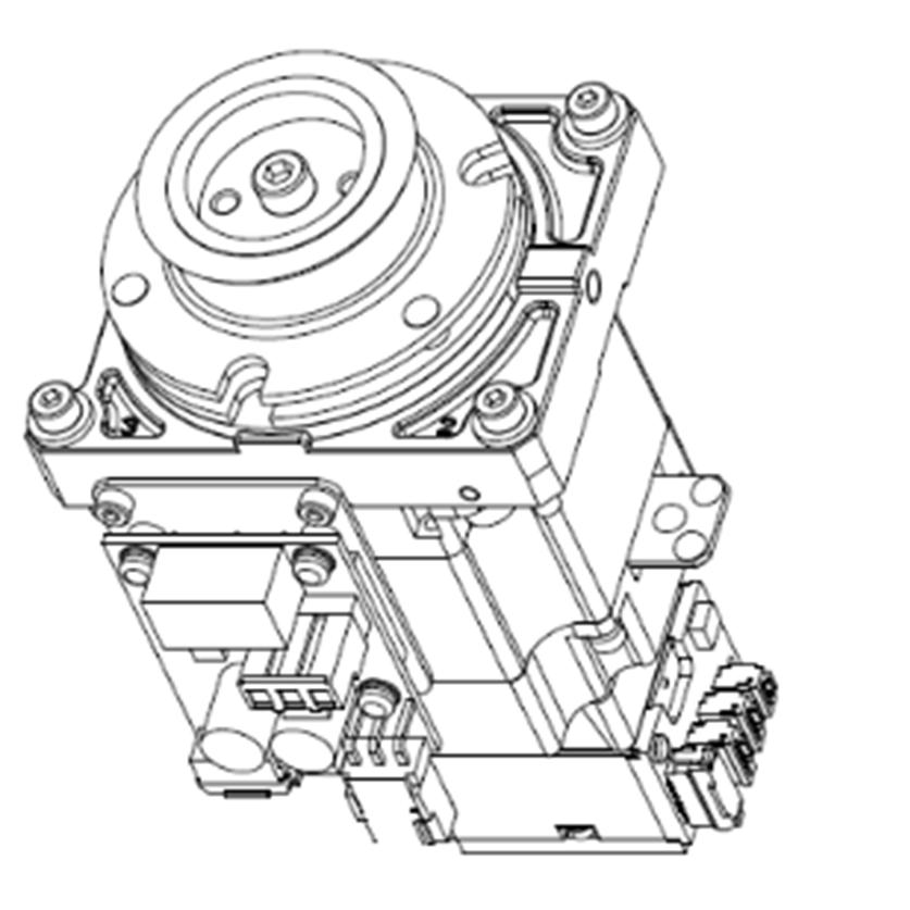

236 Maintenance 15. AMP Board Joint #4 AMP Board Joint #6 AMP Board Joint #3 AMP Board Joint #5 AMP Board Joint #2 AMP Board Joint #1 AMP Board 220 VT Rev.1
237 15.1 Replacing AMP Board on Joint #1, #2, and #3 Maintenance 15. AMP Board Name Quantity Note Maintenance parts AMP Board Hexagonal wrench width across flats: 2.5 mm 1 width across flats: 3 mm 1 For M3 hexagon socket head cap bolts For M4 hexagon socket head cap bolts Tools Torque wrench 1 For tightening torque control Cross-point screwdriver (No. 2) 1 For cross-recessed screw Nippers 1 For cutting wire tie Belt tension meter 1 Refer: Unitta U-505 Material Wire tie - The brake is mounted on each joint to prevent the arm from lowering due to its own weight while the controller power is OFF or the motor is OFF status. The brake does not work during replacement. Be careful when performing maintenance work. AMP Board Removal (1) Turn OFF the Manipulator. (2) Remove the plate (with AMP board) from the motor unit. Reference: Maintenance 9.1 Joint #1 Motor Removal Maintenance 10.1 Joint #2 Motor Removal Maintenance 11.1 Joint #3 Motor Removal (3) Remove the AMP board from the plate. NOTE Cross-recessed screws with a washer: 3-M3 6 If the thermal sheet is attached on the rear side of the AMP board, remove it. The thermal sheet will be necessary again. Be careful not to lose it. VT Rev.1 221

 Fix the plate (with AMP board) to the motor unit and mount the motor unit. Reference: Maintenance 9.")
238 Maintenance 15. AMP Board AMP Board Installation (1) If the thermal sheet is removed in the Removal step (3), attach the sheet on the plate. NOTE Attach the thermal sheet in the direction that the longer sides of the thermal sheet and the plate are parallel. As shown in the picture, the attachment position is inside the range surrounded by three spacers of the AMP board fixing part. (2) Mount the AMP board on the plate. Cross-recessed screws with a washer: 3-M3 6 Tightening torque: 0.45 ± 0.1 N m (3) Fix the plate (with AMP board) to the motor unit and mount the motor unit. Reference: Maintenance 9.1 Joint #1 Motor Installation Maintenance 10.1 Joint #2 Motor Installation Maintenance 11.1 Joint #3 Motor Installation 222 VT Rev.1

239 Maintenance 15. AMP Board 15.2 Replacing AMP Board on Joint #4 Name Quantity Note Maintenance parts AMP Board Hexagonal wrench width across flats: 3 mm 1 For M4 hexagon socket head cap bolts Tools Torque wrench 1 For tightening torque control Cross-point screwdriver (No. 2) 1 For cross-recessed screw Nippers 1 For cutting wire tie Material Wire tie - AMP Board Removal (1) Turn OFF the Manipulator. (2) Remove the plate (with AMP board) from the Arm #3. Reference: Maintenance 12.1 Joint #4 Motor Removal (3) Remove the AMP board from the plate. NOTE Cross-recessed screws with a washer: 3-M3 6 If the thermal sheet is attached on the rear side of the AMP board, remove it. The thermal sheet will be necessary again. Be careful not to lose it. AMP Board Installation (1) If the thermal sheet is removed in the Removal step (3), attach the sheet on the plate.. NOTE Attach the thermal sheet in the direction that the longer sides of the thermal sheet and plate are vertical. As shown in the picture, the attachment position is inside the range surrounded by three spacers of the AMP board fixing part. (2) Mount the AMP board on the plate. Cross-recessed screws with a washer: 3-M3 6 Tightening torque: 0.45 ± 0.1 N m (3) Mount the plate (with AMP board) on the Arm #3. Reference: Maintenance 12.1 Joint #4 Motor Installation VT Rev.1 223
240 Maintenance 15. AMP Board 15.3 Replacing AMP Board on Joint #5 and #6 Name Quantity Note Maintenance parts AMP Board Tools Hexagonal wrench width across flats: 3 mm 1 For M4 hexagon socket head cap bolts Torque wrench 1 For tightening torque control Cross-point screwdriver (No. 2) 1 For cross-recessed screw AMP Board Removal (1) Turn OFF the Manipulator. (2) Remove the Arm #4 Cover 2. Reference: Maintenance 7.5 Arm #4 Cover 2 (3) Remove the AMP board from the Arm #4 Cover 2. Cross-recessed screws with a washer: 3-M3 6 Joint #5 Joint #6 AMP Board Installation (1) Fix the AMP board on the Arm #4 Cover 2. Cross-recessed screws with a washer: 3-M3 6 Tightening torque: 0.45 ± 0.1 N m (2) Mount the Arm #4 Cover 2. Reference: Maintenance 7.5 Arm #4 Cover VT Rev.1
241 Maintenance 16. LED Plate 16. LED Plate To shut off power to the robot system, disconnect the power plug from the power source. Be sure to connect the AC power cable to a power receptacle. DO NOT connect it directly to a factory power source. WARNING Before performing any replacement procedure, turn OFF the Controller and related equipment, and then disconnect the power plug from the power source. Performing any replacement procedure with the power ON is extremely hazardous and may result in electric shock and/or malfunction of the robot system. LED Plate VT Rev.1 225
242 Maintenance 16. LED Plate 16.1 Replacing LED Plate Name Quantity Note Maintenance parts LED Plate Hexagonal wrench width across flats: 2.5 mm 1 width across flats: 3 mm 1 For M3 hexagon socket head cap bolts For M4 hexagon socket head cap bolts Tools Torque wrench 1 For tightening torque control Cross-point screwdriver (No. 2) 1 For cross-recessed screw Nippers 1 For cutting wire tie Belt tension meter 1 Refer: Unitta U-505 Material Wire tie - LED Plate Removal (1) Turn OFF the Manipulator. (2) Remove the Arm #2 Cover. Reference: Maintenance 7.2 Arm #2 Cover (3) Remove the LED plate. Cross-recessed screws: 2-M3 10 LED Plate Installation (1) Install the LED plate. Cross-recessed screws: 2-M3 10 Tightening torque: 0.45 ± 0.1 N m (2) Mount the Arm #2 Cover. Reference: Maintenance 7.2 Arm #2 Cover 226 VT Rev.1
243 Maintenance 17. Felt Sheet 17. Felt Sheet To shut off power to the robot system, disconnect the power plug from the power source. Be sure to connect the AC power cable to a power receptacle. DO NOT connect it directly to a factory power source. WARNING Before performing any replacement procedure, turn OFF the Controller and related equipment, and then disconnect the power plug from the power source. Performing any replacement procedure with the power ON is extremely hazardous and may result in electric shock and/or malfunction of the robot system. Joint #3 Felt Sheet Joint #2 Felt Sheet VT Rev.1 227
 Remove the Arm #2 Cover. Reference: Maintenance 7.2 Arm #2 Cover (2) Remove Joint #2 felt sheet from the Arm #2.")
244 Maintenance 17. Felt Sheet 17.1 Replacing Joint #2 Felt Sheet Name Quantity Note Maintenance parts Felt Sheet Joint #2 Felt Sheet Removal (1) Turn OFF the Manipulator. (2) Remove the Arm #2 Cover. Reference: Maintenance 7.2 Arm #2 Cover (2) Remove Joint #2 felt sheet from the Arm #2. Hold a slit on the one side of felt sheet to remove the sheet from the outside of the Joint #2. Joint #2 Felt Sheet Joint #2 Felt Sheet Installation (1) Hold a slit on the one side of felt sheet to remove the sheet from the outside of the Joint #2. One side of the felt sheet is a seal. Attach the felt sheet at the position where the Joint 2 screw holes and the holes of the Joint #2 felt sheet matches. (2) Mount the Arm #2 Cover. Reference: Maintenance 7.2 Arm #2 Cover 228 VT Rev.1
245 Maintenance 17. Felt Sheet 17.2 Replacing Joint #3 Felt Sheet Name Quantity Note Maintenance parts Felt Sheet Joint #3 Felt Sheet Removal (1) Turn OFF the Manipulator. (2) Remove the Arm #2 Cover. Reference: Maintenance 7.2 Arm #2 Cover (2) Remove Joint #3 felt sheet from the Arm #2. Hold a slit on the one side of felt sheet to remove the sheet from the outside of the Joint #3. Joint #3 Felt Sheet Joint #3 Felt Sheet Installation (1) Hold a slit on the one side of the Joint #3 felt sheet to remove the sheet from the outside of the Joint #3. One side of the felt sheet is a seal. Attach the felt sheet so that it fits in the groove of the Joint #3 of Arm #2. (2) Mount the Arm #2 Cover. Reference: Maintenance 7.2 Arm #2 Cover VT Rev.1 229
246 Maintenance 18. Controller Unit 18. Controller Unit WARNING Do not connect or disconnect the motor connectors while the power to the robot system is turned ON. Connecting or disconnecting the motor connectors with the power ON is extremely hazardous and may result in serious bodily injury as the Manipulator may move abnormally, and also may result in electric shock and/or malfunction of the robot system. To shut off power to the robot system, disconnect the power plug from the power source. Be sure to connect the AC power cable to a power receptacle. DO NOT connect it directly to a factory power source. Before performing any replacement procedure, turn OFF the Controller and related equipment, and then disconnect the power plug from the power source. Performing any replacement procedure with the power ON is extremely hazardous and may result in electric shock and/or malfunction of the robot system. WARNING Take meticulous care when handling the lithium battery. Improper handling of the lithium battery as mentioned below is extremely hazardous and may result in heat generation, leakage, explosion, or inflammation. It also may cause serious safety problems. <Improper Handling> Attempting to charge Deforming by pressure Disassembling Short-circuit (Polarity; Positive/Negative) Connecting batteries improperly Heating (85 C or more) Exposing to fire Soldering the terminal of the lithium battery Forcing discharge directly When disposing the battery, consult with the professional disposal services or comply with the local regulation. Make sure that the battery terminal is insulated, even for a used buttery. If the terminal contacts with the other metals, it may short and result in heat generation, leakage, explosion, or inflammation. The life span of the lithium battery varies depending on the energizing hours and installation environment of the Manipulator. It is about 7 years as a rough guide (when the Manipulator is connected to power for 8 hours a day). When the Manipulator is not connected to power, the battery consumption will significantly increase compared to when the Controller is energized. If warnings of voltage reduction occur, replace the lithium metal battery even if it has not reached the above product life. NOTE For EPSON RC+ 7.0, the recommended replacement time for the battery can be checked in the [Maintenance] dialog box. Reference: Maintenance 4. Alarm The battery may run out if it passes the recommended replacement time. If no warnings of voltage reduction occur, the calibration for all joints is not necessary. You need to perform calibration if the position moves from the originals after replaced the battery. Be sure to use the designated parts for the lithium battery. Reference: Maintenance 22. Maintenance Parts List Be careful of the battery polarity to connect it correctly. 230 VT Rev.1

247 Maintenance 18. Controller Unit 18.1 Replacing Controller Unit Make sure that orange colored charge confirmation LED on the DPB turns off when ejecting the controller unit. If operating without tuning off the LED, electric shock or other serious problems for safety may occur. DPB Board WARNING Charge confirmation LED Name Quantity Note Maintenance parts Controller Unit Tools Hexagonal wrench (width across flats: 3 mm) 1 For M4 hexagon socket head cap bolts Torque wrench 1 For tightening torque control Cross-point screwdriver (No. 2) 1 The brake is mounted on each joint to prevent the arm from lowering due to its own weight while the controller power is OFF or the motor is OFF status. The brake does not work during replacement. Be careful when performing maintenance work. VT Rev.1 231
248 Maintenance 18. Controller Unit Controller Unit Removal (1) Turn ON the Manipulator. (2) Remove the connector plate. Reference: Maintenance 7.7 Connector Plate (3) Disconnect the TP connector which is connected (inside) the connector plate. (4) Unscrew the mounting screws of the controller unit. Hexagon socket head cap bolts: 3-M4 10 (with a plain washer) (5) Pull out the controller unit from the Manipulator base. NOTE When pulling it out, firstly push the plate of the controller unit to the right (see the picture) gently, then remove the thermal sheet on the base and the controller unit. Next, pull the controller unit forward. Gently push to the right Pull it forward (6) Disconnect the following connectors of the controller unit. D A C A: Power cable connector B: Signal cable connector C: Hand I/O connector D: LED connectors 2 D B 232 VT Rev.1
 Push the controller unit into the base.")
249 Maintenance 18. Controller Unit Controller Unit Installation (1) Connect the following connectors to the controller unit. D A C A: Power cable connector B: Signal cable connector C: Hand I/O connector D: LED connectors 2 D B (2) Push the controller unit into the base. NOTE Insert the controller unit while moving it to the right (see the picture). Then, gently move the plate of the controller unit to the left and let the thermal sheet contacts with the wall inside the base. Move it to the right to insert Push to the left gently NOTE Push the controller unit while fixing the cables from the Joint #1 motor at the base opening. Be careful not to push the cables to the back of the base. VT Rev.1 233
250 Maintenance 18. Controller Unit (3) Fix the controller unit to the base. Hexagon socket head cap bolts: 3-M4 10 (with a plain washer) Tightening torque: 4.0 ± 0.2 N m (4) Connect the TP connector inside the connector plate. (5) Mount the connector plate. Reference: Maintenance 7.7 Connector Plate 234 VT Rev.1
251 Maintenance 18. Controller Unit 18.2 Replacing Power Board Name Quantity Note Maintenance parts Power Board Tools Cross-point screwdriver (No. 2) 1 Power Board Removal (1) Remove the controller unit. Reference: Maintenance 18.1 Replacing Controller Unit (2) Disconnect the connectors of the power board. Power connectors (IN/OUT 2 for each) (3) Remove the power board. Pan head screws: 10-M3 8 Sems IN OUT Power Board Installation (1) Mount a new power board. Pan head screws: 10-M3 8 Sems Tightening torque: 0.45 ± 0.1N m (2) Connect the connectors of the power board. Power connectors (IN/OUT 2 for each) (3) Mount the controller unit. Reference: Maintenance 18.1 Replacing Controller Unit VT Rev.1 235
252 Maintenance 18. Controller Unit 18.3 Replacing CPU/DPB Board Maintenance parts Name Quantity Note CPU/DPB Board Tools Cross-point screwdriver (No. 2) 1 CPU/DPB Board Removal (1) Remove the power board. Reference: Maintenance 18.2 Replacing Power Board (2) Disconnect the CPU/DPB board connectors. NOTE E: Power connector (IN/OUT 1 for each) F: Cooling fan connector G: Regenerative resistor connector 1 H: Regenerative resistor connector 2 Remember the cable layout for reconnecting after replacement. F G H (3) Remove the CPU/DPB board. E-OUT E-IN Binding head screws: 5-M3 6 NOTE Firstly, unscrew the mounting screws. Next, pull the CPU/DPB board to the arrow direction. (4) Remove the thermal sheet attached on the CPU board. Thermal sheet NOTE The thermal sheet will be necessary again. Be careful not to lose them. Be careful not to break the thermal sheet. (5) Attach the thermal sheet on the surface (the side with no connectors) of the new CPU/DPB board NOTE Make sure not to attach the sheet on the wrong surface. 236 VT Rev.1
253 Maintenance 18. Controller Unit CPU/DPB Board Installation (1) Attach the thermal sheet on the surface (the side with no connectors) of the new CPU/DPB board NOTE Make sure not to attach the sheet on the wrong surface. Thermal sheet (2) Mount the CPU/DPB board and fix it by the mounting screws. Binding head screws: 5-M3 6 Tightening torque: 0.45 ± 0.1N m (3) Connect the CPU/DPB board connectors. E: Power connector (IN/OUT 1 for each) F: Cooling fan connector G: Regenerative resistor connector 1 H: Regenerative resistor connector 2 F G H NOTE Be careful not to connect the wrong connectors or forget to connect it. (4) Mount the power board. E-OUT E-IN Reference: Maintenance 18.2 Replacing Power Board VT Rev.1 237

254 Maintenance 18. Controller Unit 18.4 Replacing Lithium Battery Maintenance parts NOTE Lithium Battery Removal Name Quantity Note Lithium Battery Replace the battery within 30 minutes after turning OFF. If more than 30 minutes pass after removing the battery, voltage of the capacitor lower and time may be reset. (1) Remove the CPU/DPB board from the base. Reference: Maintenance 18.3 Replacing CPU/DPB Board (2) Remove the battery from the battery connector. Lithium Battery Installation (1) Connect a new battery to the battery connector. (2) Mount the CPU/DPB board to the base. Reference: Maintenance 18.3 Replacing CPU/DPB Board 238 VT Rev.1
 1 Cooling Fan Removal (1) Remove the controller unit. Reference: Maintenance 18.1 Replacing Controller Unit (2) Remove the cooling fan.")
255 Maintenance 18. Controller Unit 18.5 Replacing Cooling Fan Name Quantity Note Maintenance parts Cooling Fan Tools Cross-point screwdriver (No. 2) 1 Cooling Fan Removal (1) Remove the controller unit. Reference: Maintenance 18.1 Replacing Controller Unit (2) Remove the cooling fan. Binding head screws: 4-M4 30 Cooling Fan Installation (1) Mount a new cooling fan. Binding head screws: 4-M4 30 Tightening torque: 0.45 ± 0.1N m Cooling Fan (2) Mount the controller unit. Reference: Maintenance 18.1 Replacing Controller Unit VT Rev.1 239
256 Maintenance 18. Controller Unit 18.6 Replacing SD Card Maintenance parts Name Quantity Note SD Card Tools Cross-point screwdriver (No. 2) 1 NOTE Remove the SD card after removing the fieldbus I/O module if fieldbus I/O module is inserted to the optional slot. Also, install fieldbus I/O module after installing the SD card. For more details about fieldbus I/O module, refer to the following. Setup & Operation 17: Fieldbus I/O. SD Card Removal (1) Turn OFF the Manipulator. (2) Remove the power plug. (3) Remove the optional slot cover. Pan head screws: 2-M3 6 Sems (4) Push the SD card which is inserted near the optional slot to eject. Optional slot cover SD Card Installation (1) Push the SD card and inset to the SD card slot near the optional slot. (2) Mount the optional slot cover. Pan head screws: 2-M3 6 Sems Tightening torque: 0.45 ± 0.1N m 240 VT Rev.1
257 19. Calibration 19. Calibration 19.1 Overview After parts have been replaced (motors, reduction gear units, timing belts, etc.), the Manipulator cannot perform positioning properly because a gap exists between the origin stored in each motor encoder and its corresponding origin stored in the Controller. Therefore, it is necessary to match these origins after replacing the parts. The process of aligning the two origins is called Calibration. Note that calibration is not the same as teaching*. * Teaching means to teach the Controller coordinate points (including poses) anywhere in the operating area of the Manipulator. To ensure safety, a safeguard must be installed for the robot system. For details on the safeguard, refer to the Installation and Design Precautions in the Safety chapter of the EPSON RC+ User s Guide. WARNING Before operating the robot system, make sure that no one is inside the safeguarded area. The robot system can be operated in the mode for teaching even when someone is inside the safeguarded area. The motion of the Manipulator is always in restricted (low speeds and low power) status to secure the safety of an operator. However, operating the robot system while someone is inside the safeguarded area is extremely hazardous and may result in serious safety problems in case that the Manipulator moves unexpectedly. In EPSON RC+, a coordinate point including the arm pose is defined as point and its data is called point data. There are two methods to move the Manipulator during calibration. - Releasing the electromagnetic brake and moving the arms manually. For details, refer to the Setup & Operation 1.5 How to Move Arms with the Electromagnetic Brake. - Moving the Manipulator using Jog & Teach. Moving the Manipulator while releasing the electromagnetic brake involves risk as described below. It is recommended to move the Manipulator using Jog & Teach. Normally, release the brake of joints one by one. Take extra care if you need to release the brakes of two or more joints simultaneously. Releasing the brakes of two or more joints simultaneously may cause hands and fingers to be caught and/or equipment damage or malfunction of the Manipulator as the arms of the Manipulator may move in unexpected directions. CAUTION Be careful of the arm falling when releasing the brake. While the brake is being released, the Manipulator s arm falls by its own weight. The arm falling may cause hands and fingers to be caught and/or may cause equipment damage or malfunction of the Manipulator. VT Rev.1 241
258 19. Calibration Also, pay attention to the following points at the encoder initialization. CAUTION NOTE Joint #4 have no mechanical stops and they may be rotated more than 360 degrees. If the encoder initialization is performed with improper posture, the Manipulator moves outside the operation range. If the Manipulator was moved outside the operation range, the internal wiring may be damaged by being twisted or pinched and it may result in Manipulator malfunction. When the origin position of the Joint #4 is uncertain, check torsion of the internal cables. The origin position is where the Manipulator has the internal cables not twisted at the basic orientation described in Setup & Operation 3.9 Checking the Basic orientation. Torsion of the internal cables can be checked by removing the following cover. Joint #4 : Arm #3 Cover 3-M4 12 Sems Arm #3 Cover For details on Jog & Teach, refer to the following manual. EPSON RC+ User s Guide [Tools]-[Robot Manager]-[Jog and Teach] Page NOTE - For details about the basic orientation, refer to Setup & Operation 3.9 Checking the Basic orientation. - Calibrate one joint at a time. (Also, replace parts of one joint at a time.) If you calibrate the origins for multiple joints simultaneously, it will be more difficult to verify their origins and obtain the origin correct positions. 242 VT Rev.1
259 19. Calibration Calibration Flowchart Start 1. Basic Orientation Confirmation 2. Part Replacement 3. Encoder Initialization 4. Calibration 5. Calibration More accurate positioning Perform these steps if necessary 6. Accuracy Testing Yes Re-calibrate? No End VT Rev.1 243
260 19. Calibration 19.2 Calibration Procedures Command Input Command execution is required in some calibration procedures. Select the EPSON RC+ menu-[tools]-[command Window]. This step is omitted in the calibration procedures. Jog Motion Setting of the jog motion is required in some calibration procedures. Select EPSON RC+ menu-[tools]-[robot Manager] and select the [Jog & Teach] page. The page above is indicated as [Jog & Teach] in the calibration procedures. Follow steps 1 to 6 to calibrate the Manipulator. 1. Basic Orientation Confirmation Calibration is performed with the basic orientation of the Manipulator. For details about the basic orientation, refer to Setup & Operation 3.9 Checking the Basic Orientation. When the Manipulator cannot have the basic orientation, define the reference orientation in advance, and record the point data. Also, put the match marks to indicate the orientation. The coordinate points including the Arm orientation are referred to as points, and the data of the points are called point data in EPSON RC+. 2. Part Replacement Replace the parts as instructed in this manual. Be careful not to injure yourself or damage parts during part replacement 3. Encoder Initialization Follow the procedures below to initialize the encoder. Execute the following command in the [Command Window]. EPSON RC+ >Encreset [The joint number (1 to 6) of the encoder to be reset] Select EPSON RC+ menu-[tools]-[controller], then click <Reset Controller>. 244 VT Rev.1
261 19. Calibration 4. Calibration EPSON RC+ 4-1 Visually move the calibrating Joint of the Manipulator to the basic orientation Set the jog mode to Joint in the [Jog & Teach] panel from EPSON RC+ menu - [Tools] - [Robot Manager], and then move the Manipulator in Jog motion so that the target joint matches the basic orientation as much as possible. When the Manipulator cannot have the basic orientation, move the Manipulator so that the marks depending on the predetermined reference orientation are aligned. 4-2 Initialize the Encoder EPSON RC+ Execute the command in the [Command Window] from EPSON RC+ menu - [Tools] according to the joint to adjust as follows. 4-3 Reboot the controller Joint #1 >Encreset 1 Joint #2 >Encreset 2 Joint #3 >Encreset 3 Joint #4 >Encreset 4 Joint #5 >Encreset 5, 6 Joint #6 >Encreset 6 EPSON RC+ Click EPSON RC+ menu-[tool]-[controller]-<reset Controller>. 4-4 Specify a pulse value set as an origin point EPSON RC+ Execute the command in the [Command Window] from EPSON RC+ menu - [Tools] according to the joint to adjust as follows. >calpls J1 pulse, J2 pulse, J3 pulse, J4 pulse, J5 pulse, J6 pulse * Manipulator will not move. Specify the pulse values 0 when the Manipulator is aligned to the basic orientation, or the values recorded at the predetermined reference orientation (where the match marks are aligned) to the command parameters (pulse values). If the point data for the reference orientation is P1, the command parameters can be specified as follows >calpls ppls(p1,1), ppls(p1,2), ppls(p1,3), ppls(p1,4), ppls(p1,5), ppls(p1,6) VT Rev.1 245
262 19. Calibration 4-5 Set the specified pulse value to the encoder EPSON RC+ NOTE Execute the command in the [Command Window] from EPSON RC+ menu - [Tools] according to the joint to adjust as follows. Joint #1 >calib 1 Joint #2 >calib 2 Joint #3 >calib 3 Joint #4 >calib 4 Joint #5 >calib 5,6 Joint #6 >calib 6 When the origin of the Joint #5 is calibrated, the Joint #6 will be out of position. (Due to the structure of the Manipulator, any offset in the position of the Joint #5 affects the Joint #6.) Calibrate the origin of the Joint #6 together when calibrating the Joint #5. Move the arm to several points to check if the arm moves to the original positions properly. Teach points if fine adjustment is necessary. 246 VT Rev.1
263 19. Calibration 5. Calibration (More accurate positioning) EPSON RC+ Move the Manipulator to the selected point data by jogging in [Jog & Teach]. Move the joint* which is not calibrated to the specified point by motion command. *When the Joint #5 is calibrated, adjust the Joints #1 - #4. For example, when the selected point data is P1, execute Motor On in [Control Panel] and execute Go P1 in [Jog & Teach]. Adjust the calibrated joints accurately by jog command so that the end effector is aligned to the selected point data position. *When the Joint #5 is calibrated, adjust the Joint #5 and #6. Select the Joint jog mode from [Jog & Teach] to change and adjust the angle of the calibrated joint. Set the pulse values again at the adjusted point. Execute the following command in the [Command Window] from EPSON RC+ menu - [Tools] to specify the pulse values to set. >calpls J1 pulse, J2 pulse, J3 pulse, J4 pulse, J5 pulse, J6 pulse * Manipulator will not move. Specify the pulse values of the selected point data to the command parameters. If the point data for the reference orientation is P1, the command parameters can be specified as follows >calpls ppls(p1,1), ppls(p1,2), ppls(p1,3), ppls(p1,4), ppls(p1,5), ppls(p1,6) * Manipulator will not move. Then, execute the following command in the [Command Window] to set the specified pulse values to the encoder according to the joint to set the origin point. Joint #1 : >Calib 1 Joint #2 : >Calib 2 Joint #3 : >Calib 3 Joint #4 : >Calib 4 Joint #5 : >Calib 5,6 Joint #6 : >Calib 6 6. Accuracy Testing Move the Manipulator to a different pose (point) to verify whether it moves back to the original position. If accuracy is inadequate, it is necessary to re-calibrate the origin using a different pose (point). You must set the pose (point) again if the Manipulator does not move back to the original position after re-calibration. VT Rev.1 247
264 20. Restrictions 20. Restrictions For VT series manipulator, there are commands with restrictions or may cause an error if executing. However, error does not occur when building a program. Also, some functions have restrictions Commands Cannot Use The following commands/ functions are not available. AbortMotion Toff Ton ShutDown WindowsStatus Aborts a motion command and puts the running task in error status. Turns off execution line display on the LCD. Specifies a task which shows an execution line on the LCD. Shuts down EPSON RC+ and optionally shuts down or restarts Windows. Returns the Windows startup status Commands Cause Motion Error If Specifying RS-232C If specifying RS-232C port of the controller, the following commands/ functions cause motion error. Input # Print # Line Input # Lof Read ReadBin Write WriteBin Allows string or numeric data to be received from a file, communications port, or database and stored in one or more variables. Outputs data to the specified file, communications port, database, or device. Reads data of one line from a file, communication port, database, or the device. Checks whether the specified RS-232 or TCP/IP port has any lines of data in its buffer. Reads characters from a file or communications port. Reads binary data from a file or communications port. Writes characters to a file or communication port without end of line terminator. Writes binary data to a file or communications port. 248 VT Rev.1
265 20. Restrictions 20.3 Commands Cause Error Conveyor Tracking Commands If executing conveyor tracking commands/functions, motion error occurs. Cnv_AbortTrack Cnv_Accel Function Cnv_Accel Cnv_Downstream Function Cnv_Downstream Cnv_Fine Function Cnv_Fine Cnv_Flag Function Cnv_Mode Function Cnv_Mode Cnv_Name$ Function Cnv_Number Function Cnv_OffsetAngle Cnv_OffsetAngle Function Cnv_Point Function Cnv_PosErr Function Cnv_Pulse Function Cnv_QueAdd Cnv_QueGet Function Cnv_QueLen Function Cnv_QueList Cnv_QueMove Cnv_QueReject Cnv_QueReject Function Cnv_QueRemove Cnv_QueUserData Cnv_QueUserData Function Aborts tracking motion to a conveyor queue point. Returns acceleration and deceleration for the conveyor Sets acceleration and deceleration for the conveyor Returns the downstream limit for the specified conveyor. Sets the downstream limit for the specified conveyor. Returns the current Cnv_Fine setting. Sets the value of Cnv_Fine for one conveyor. Returns the tracking state of the robot Returns the setting mode value of the conveyor Sets the setting mode value of the conveyor Returns the name of the specified conveyor. Returns the number of a conveyor specified by name. Sets the offset value for the conveyor queue data. Returns the offset value of the conveyor queue data. Returns a robot point in the specified conveyor's coordinate system derived from sensor coordinates. Returns deviation in current tracking position compared to tracking target. Returns the current position of a conveyor in pulses. Adds a robot point to a conveyor queue. Returns a point from the specified conveyor's queue. Returns the number of items in the specified conveyor's queue. Displays a list of items in the specified conveyor's queue. Moves data from upstream conveyor queue to downstream conveyor queue. Sets and displays the queue reject distance for a conveyor. Returns the current part reject distance for a conveyor. Removes items from a conveyor queue. Sets and displays user data associated with a queue entry. Returns the user data value associated with an item in a conveyor queue. Cnv_RobotConveyor Function Returns the conveyor being tracked by a robot. Cnv_Speed Function Returns the current speed of a conveyor. Cnv_Trigger Latches current conveyor position for the next Cnv_QueAdd statement. Cnv_Upstream Function Returns the upstream limit for the specified conveyor. Cnv_Upstream Sets the upstream limit for the specified conveyor. VT Rev.1 249
266 20. Restrictions PG Commands If executing PG commands, motion error occurs. PG_FastStop PG_LSpeed PG_Scan PG_SlowStop Stops the PG axes immediately. Sets the pulse speed of the time when the PG axis starts accelerating and finishes decelerating. Starts the continuous spinning motion of the PG robot axes. Stops slowly the PG axis spinning continuously R-I/O Commands If executing R-I/O commands/functions, motion error occurs. LatchEnable LatchState Function LatchPos Function SetLatch Enable/Disable the latch function for the robot position by the R-I/O input. Returns the latch state of robot position using the R-I/O. Returns the robot position latched using the R-I/O input signal. Sets the latch function of the robot position using the R-I/O input Force Sensing Commands If executing force sensing commands/functions, motion error occurs. Force_Calibrate Force_ClearTrigger Force_GetForces Force_GetForce Function Force_Sensor Force_Sensor Function Force_SetTrigger Sets zero offsets for all axes for the current force sensor. Clears all trigger conditions for the current force sensor. Returns the forces and torques for all force sensor axes in an array. Returns the force for a specified axis. Sets the current force sensor for the current task. Returns the current force sensor for the current task. Sets the force trigger for the Till command Other (FineDist) You cannot use the command: FineDist Robot determines the position by set value of Fine even if using FineDist. Fine FineDist Specifies and displays the positioning error limits. (Unit: pulse) Specifies and displays the positioning error limits (Unit: mm) Other (HealthCalcPeriod) You cannot use the command: HealthCalcPeriod A period of parts consumption commands information to calculate remaining months is one day and unable to change. HealthCalcPeriod Set the calculation period of parts consumption commands. HealthCalcPeriod Function Returns the calculation period of parts consumption commands Other (ChDisk) You cannot specify USB option to the command: ChDisk 250 VT Rev.1
267 20. Restrictions 20.4 Restrictions of Functions Some of the following functions are not available TP3 You cannot use build of the program. An error occurs to finish the program if executing it. Other functions are available Loop Processing If the created robot control program is consisted of the multi-tasking and also there are some task with infinite loop, the system may become unstable and the connection with EPSON RC+ is disconnected. The controller detects infinite loop tasks. If the possibilities to affect the system are detected, the following error occurs and stops the program. If the error occurs, modify the program and make sure not to set infinite loop. Error code : 2556 Error message : An excessive loop was detected. Please reduce the number of looped tasks or set Wait Do not perform any processing such as infinite loop or any other similar processing as much as possible. Execute wait command or similar command in the loop processing and avoid occupying the CPU if performing calculation which required loop or waiting for I/O signals. There is no problem if executing commands with Wait in the loop such as Wait command, robot operating command, Print command, and NetWait command. NOTE: About infinite loop Infinite loop is when commands are created only with command without Wait in the loop such as operation instruction, assignment command, and I/O check command. Example 1: Turns ON output port 2 when Input port 0 turned ON Example of program that may cause errors Do If Sw(0) = On Then On(2) Exit Do EndIf Loop Correction example Wait Sw(0) = On On(2) VT Rev.1 251
268 20. Restrictions Example 2: When performing the large amount of calculation with a loop structure. Example of program that may cause errors For i = 0 To For j = 0 To a = a + 1 Next Next Correction example For i = 0 To For j = 0 To a = a + 1 Next Wait 0.01 ' Execute Wait to avoid occupying the CPU Next Camera Searching by CV1/CV2 You may not be able to use Camera searching by VT series Manipulator if CV1/CV2 is used and the following two conditions are fulfilled. - When connecting PC and VT series Manipulator by USB connection - When the configuration of default gateway of VT series Manipulator is None, or Type IP address for CV1/ CV2 manually when you cannot use Camera researching. For more details of Camera researching, refer to the following. Vision Guide 7.0 Hardware & Setup Setup: CV1/CV2 Camera Configuration Restore the Data of Backup Controller Function Backup controller function that acquired by virtual controller cannot be restored to VT series Manipulator. NOTE : Backup controller function that acquired by actual equipment can be restored to VT series Manipulator. 252 VT Rev.1
269 21. Error Code Table 21. Error Code Table For error code, refer to the following manual. EPSON RC+7.0 SPEL+ Language Reference SPEL+ Error Messages VT Rev.1 253
270 22. Maintenance Parts List 22. Maintenance Parts List Cover Part Name Code Note Arm # Arm # Arm # Arm # Reference: Maintenance Overhaul *3 Cable unit , 8.2 Joint # W unit Joint # AC servo motor Joint # W unit 11.1 Joint # W unit Joint #5, # , 14.1 Joint #1, # , 10.2 Reduction gear unit* *1 Joint #3, # , 12.2 Joint #5, # , 14.2 Joint # mm 9.1, 9.3 Joint # Width 9 mm 501mm 10.1, 10.3 Timing belt Joint # mm 11.1, 11.3 Joint # mm 12.1, 12.3 Joint #5, # Width 6 mm 13.1, mm 14.1, 14.3 Thermal sheet For motor 9.1, 10.1, 11.1 AMP board For motor 15.1, 15.2, 15.3 LED plate Arm #2 16 Felt sheet Joint # Arm #2 Joint # Controller unit CPU board, DPB board, 18.1 Cooling fan unit Power board With: battery CPU/DPB board Without: SD, Thermal sheet Lithium battery Cooling fan SD card VT Rev.1

271 22. Maintenance Parts List Part Name Code Note Reference: Maintenance SK-1A Joint #1, #2, #3, #4-9.2, 10.2, 11.2, 12.2 Grease *3 SK-2 Joint #5, #6, - For purchasing grease, and Bevel gear adhesive, please contact 13.2, 14.2 GPL-224 Cable - the sales company in your 8.1, 8.2 region. 9.2, 10.2, 11.2, 12.2, 13.2 Adhesive *3 LOCTITE Wire tie AB bag (100 pcs: white) AB bag (100 pcs: white) 8.1, 8.2 *1 Reduction Gear Unit: A reduction gear unit consists of the following three parts. When replacing the reduction gear unit, be sure to replace these parts all together as a set. Waveform generator The waveform generator consists of an ellipsoidal cam and ball bearings on outer circumference. The inner ring of the bearings is secured to the cam, while the outer ring is capable of flexible deformation through the ball bearings. Flexspline A thin, elastic, cup-shaped metal body with gear teeth around the outer circumference of the opening. Circular spline A rigid, ring-shaped body with gear teeth on the inner circumference. The circular spline has two more teeth than the flexspline does. Waveform generator Circular spline Flexspline The splines are greased. Be sure to keep the grease from being attaching to the clothes. *2 Overhaul: As a rough indication, perform the overhaul (parts replacement) before reaching 20,000 operation hours of the Manipulator. The operation hours can be checked in [Controller Status Viewer] dialog - [Motor On Hours]. For details, refer to Maintenance 2.2 Overhaul. VT Rev.1 255
SCARA ROBOT. G1 series MANIPULATOR MANUAL
 SCARA ROBOT G1 series MANIPULATOR MANUAL Rev.11 EM16XR3291F MANIPULATOR MANUAL G1 series Rev.11 SCARA ROBOT G1 series Manipulator Manual Rev.11 Copyright 2009-2016 SEIKO EPSON CORPORATION. All rights reserved.
SCARA ROBOT. LS series MANIPULATOR MANUAL
 SCARA ROBOT LS series MANIPULATOR MANUAL Rev.11 EM179R3531F MANIPULATOR MANUAL LS series Rev.11 SCARA ROBOT LS series Manipulator Manual Rev.11 Copyright 2011-2017 SEIKO EPSON CORPORATION. All rights reserved.
SCARA ROBOT. G3 series MANIPULATOR MANUAL
 SCARA ROBOT G3 series MANIPULATOR MANUAL Rev.13 EM179R3525F MANIPULATOR MANUAL G3 series Rev.13 SCARA ROBOT G3 series Manipulator Manual Rev.13 Copyright 2008-2017 SEIKO EPSON CORPORATION. All rights reserved.
RS3-55 series SCARA ROBOT MANIPULATOR MANUAL
 SCARA ROBOT RS3-55 series MANIPULATOR MANUAL Rev.1 EM108R2070F This manual describes the information on how to use RS3-55 series. For other information, refer to RS series manipulator manual. MANIPULATOR
SCARA ROBOT. LS20 series MANIPULATOR MANUAL
 SCARA ROBOT LS20 series MANIPULATOR MANUAL Rev.5 EM183R3615F MANIPULATOR MANUAL LS20 series Rev.5 SCARA ROBOT LS20 series Manipulator Manual Rev.5 Copyright 2016-2018 SEIKO EPSON CORPORATION. All rights
SCARA ROBOT. E2H series MANIPULATOR MANUAL
 SCARA ROBOT E2H series MANIPULATOR MANUAL Rev. 4 EM069R1411F MANIPULATOR MANUAL E2H series Rev. 4 SCARA ROBOT E2H series Manipulator Manual Rev. 4 Copyright 2004-2006 SEIKO EPSON CORPORATION. All rights
SCARA ROBOT. E2C series MANIPULATOR MANUAL
 SCARA ROBOT E2C series MANIPULATOR MANUAL Rev. 6 EM069R1409F MANIPULATOR MANUAL E2C series Rev. 6 SCARA ROBOT E2C series Manipulator Manual Rev. 6 E2C Rev.6 Copyright 2002-2006 SEIKO EPSON CORPORATION.
ROBOT CONTROLLER / Drive Unit RC700DU / RC700DU-A
 ROBOT CONTROLLER / Drive Unit RC700DU / RC700DU-A Rev.8 EM16XC3313F ii ROBOT CONTROLLER / Drive Unit RC700DU / RC700DU-A Rev.8 ROBOT CONTROLLER / DRIVE UNIT RC700DU / RC700DU-A Rev.8 Copyright 2014-2016
SCARA ROBOT. G1 series MANIPULATOR MANUAL
 SCARA ROBOT G1 series MANIPULATOR MANUAL Rev.7 EM151R2853F MANIPULATOR MANUAL G1 series Rev.7 SCARA ROBOT G1 series Manipulator Manual Rev.7 G1 Rev.7 Copyright 2009-2015 SEIKO EPSON CORPORATION. All rights
SCARA ROBOT. G6 series MANIPULATOR MANUAL
 SCARA ROBOT G6 series MANIPULATOR MANUAL Rev.15 EM151R2857F MANIPULATOR MANUAL G6 series Rev.15 SCARA ROBOT G6 series Manipulator Manual Rev.15 Copyright 2007-2015 SEIKO EPSON CORPORATION. All rights reserved.
SCARA ROBOT. G10 / G20 series MANIPULATOR MANUAL
 SCARA ROBOT G10 / G20 series MANIPULATOR MANUAL Rev.16 EM158R3023F MANIPULATOR MANUAL G10 / G20 series Rev.16 SCARA ROBOT G10 / G20 series Manipulator Manual Rev.16 Copyright 2007-2015 SEIKO EPSON CORPORATION.
Safety and Installation
 RC520 Safety and Installation Read this manual first Rev.2 EM089B1742F RC520 Safety and Installation Rev.2 RC52 0 Safety and Installation Rev.2 Copyright 2007-2008 SEIKO EPSON CORPORATION. All rights reserved.
SCARA ROBOT. G6 series MANIPULATOR MANUAL
 SCARA ROBOT G6 series MANIPULATOR MANUAL Rev.13 EM129R2376F MANIPULATOR MANUAL G6 series Rev.13 SCARA ROBOT G6 series Manipulator Manual Rev.13 G6 Rev.13 Copyright 2007-2012 SEIKO EPSON CORPORATION. All
SCARA ROBOT. G10 / G20 series MANIPULATOR MANUAL. Rev.12 EM129R2377F
 SCARA ROBOT G10 / G20 series MANIPULATOR MANUAL Rev.12 EM129R2377F MANIPULATOR MANUAL G10 / G20 series Rev.12 SCARA ROBOT G10 / G20 series Manipulator Manual Rev.12 G10 / G20 Rev.12 Copyright 2007-2012
Robot System. Safety and Installation. Robot Controller RC620 Programming Software EPSON RC+6.0. Manipulator G series RS series C3 series S5 series X5
 Robot System Safety and Installation Read this manual first Rev.12 EM15XB3080F Robot Controller RC620 Programming Software EPSON RC+6.0 Manipulator G series RS series C3 series S5 series X5 Safety and
Robot System. Safety and Installation. Robot Controller RC180 Programming Software EPSON RC+5.0. Manipulator G series RS series C3 series S5 series
 Robot System Safety and Installation Read this manual first Rev.21 EM153B2933F Robot Controller RC180 Programming Software EPSON RC+5.0 Manipulator G series RS series C3 series S5 series Robot System Safety
Product Specification
 Product Specification IRB 6400S 3HAC 9121-1 / Rev. 1 M2000 The information in this document is subject to change without notice and should not be construed as a commitment by ABB Automation Technologies,
Cat. No. I526-E1-1 USER S MANUAL 3G3IV-PLKEB2 /4. Braking Resistor Units 3G3IV-PCDBR2 B/4 B. Braking Units
 Cat. No. I526-E1-1 USER S MANUAL 3G3IV-PLKEB2 /4 Braking Resistor Units 3G3IV-PCDBR2 B/4 B Braking Units Thank you for choosing an OMRON Braking Resistor Unit and Braking Unit. Proper use and handling
Contents. Introduction Inspection Notes on Safety Precautions. Chapter 1 Overview Product Overview Names of Parts 2
 INSTRUCTION MANUAL Contents Introduction Inspection Notes on Safety Precautions i i ii vii Chapter 1 Overview 1 1.1 Product Overview 1 1.2 Names of Parts 2 Chapter 2 Specifications 5 2.1 Product Specifications
SCARA ROBOT. RS series MANIPULATOR MANUAL
 SCARA ROBOT RS series MANIPULATOR MANUAL Rev.5 EM105R2014F MANIPULATOR MANUAL RS series Rev.5 SCARA ROBOT RS series Manipulator Manual Rev.5 Copyright 2008-2010 SEIKO EPSON CORPORATION. All rights reserved.
Cat. No. I159E-EN-01. SCARA Robots ZX-T XG Series. R6Y - XGC/XGP series MAINTENANCE MANUAL
 Cat. No. I159E-EN-01 SCARA Robots ZX-T XG Series R6Y - XGC/XGP series MAINTENANCE MANUAL CONTENTS XGC/XGP Maintenance Manual Safety Instructions 1. Safety Information S-1 2. Signal words used in this
User Manual. Solar Charge Controller 3KW
 User Manual Solar Charge Controller 3KW 1 CONTENTS 1 ABOUT THIS MANUAL... 3 1.1 Purpose... 3 1.2 Scope... 3 1.3 SAFETY INSTRUCTIONS... 3 2 INTRODUCTION... 4 2.1 Features... 4 2.2 Product Overview... 5
Installation and Connection Manual
 Installation and Connection Manual E Controller Kawasaki Heavy Industries, Ltd. 90202-1204DEA Preface Preface This manual describes the installation and connection of Kawasaki Painting Robot KJ series.
Extended Panel Operation Manual RKP001Z-0
 Extended Panel Operation Manual RKP001Z-0 Table of Contents 1. NAMES AND FUNCTIONS OF MAIN PARTS...3 2. CONNECTION AND START-UP...4 3. DIMENSIONS...5 4. PROTECTION FUNCTION...6 5. SPECIFICATIONS...6 6.
BEFORE USING THE PRODUCT
 HL-17015-5 BEFORE USING THE PRODUCT Thank you for purchasing an Oriental Motor product. Please read this BEFORE USING THE PRODUCT and the separate manual entitled OPERATING MANUAL thoroughly to ensure
Mod: KLD6-12/35XLAS-N
 12/2011 Mod: KLD6-12/35XLAS-N Production code: 1914070 INSTRUCTION MANUAL LOGIC LINE PLUS HOOD Reseller Stamp for Warranty Dear customer, Above all, thank you for choosing our product and we would like
Product Specification
 Product Specification IRB 640 3HAC 9217-1 / Rev. 1 M2000 The information in this document is subject to change without notice and should not be construed as a commitment by ABB Automation Technologies,
Cat. No. I194E-EN-03B. Washdown Delta Robot ZX-T Series. Delta Robot IP67 Mini Delta Robot IP67 INSTALLATION MANUAL
 Cat. No. I194E-EN-03B Washdown Delta Robot ZX-T Series R6Y3 Series Delta Robot IP67 Mini Delta Robot IP67 INSTALLATION MANUAL CONTENTS R6Y3 Installation Manual Safety Instructions 1. Safety Information
SG-B1 SERIES / SG-A1 SERIES
 643 Door with Solenoid Interlock / Door Ultra-slim SG-B1 SERIES / SG-A1 SERIES Related Information General terms and conditions... F-7 General precautions... P.1501 PHOTO PHOTO Conforming to Machine &
Technical Documentation
 Technical Documentation Product manual Holding brake controller Document: 0198441113316 Edition: V1.00, 03.2006 Important information The drive systems described here are products for general use that
I. Safety precautions
 . Safety precautions The items described in these instructions and on the inverter itself are very important so that you can use the inverter safely, prevent injury to yourself and other people around
R-SERIES MULTI-AXIS INDUSTRIAL ROBOTS
 Automation Solutions R-SERIES MULTI-AXIS INDUSTRIAL ROBOTS COMPACT MULTI-AXIS INDUSTRIAL ROBOTS FOR COMPLEX PROCESSING TASKS Reduce Manufacturing Costs Improve Production Time Increase Throughput Engineering
Lumitester PD-30. Instruction Manual. Table of Contents
 Table of Contents Lumitester PD-30 Instruction Manual Thank you very much for purchasing the Lumitester PD-30. All of this Instruction Manual must be read before operation of this product for safe and
User's Manual. MV100 Rechargeable Battery Model. Yokogawa Electric Corporation. IM MV100-41E 1st Edition
 User's Manual MV100 Rechargeable Battery Model Yokogawa Electric Corporation 1st Edition Thank you for purchasing the MV100 Rechargeable Battery Model. This user s manual describes the rechargeable batteries.
miconverter 18-Module Rack-Mount Power Chassis User Manual 38 Tesla, Irvine, CA USA Phone: (949) ; Fax: (949) Page 12
 ; Fax: (949) Page 12") miconverter 18-Module Rack-Mount Power Chassis User Manual Page 12 38 Tesla, Irvine, CA 92618 USA Phone: (949) 250-6510; Fax: (949) 250-6514 General and Copyright Notice This publication is protected by
miconverter 18-Module Rack-Mount Power Chassis User Manual Page 12 38 Tesla, Irvine, CA 92618 USA Phone: (949) 250-6510; Fax: (949) 250-6514 General and Copyright Notice This publication is protected by
User s Manual Power Supply. IM E 2nd Edition. Yokogawa Electric Corporation
 User s Manual 701934 Power Supply Yokogawa Electric Corporation 2nd Edition Foreword Revisions Thank you for purchasing the 701934 Power Supply. This user's manual contains useful information about the
F-4600 INLINE ULTRASONIC FLOW METER Installation and Operation Guide
 F-4600 INLINE ULTRASONIC FLOW METER Installation and Operation Guide 11451 Belcher Road South, Largo, FL 33773 USA Tel +1 (727) 447-6140 Fax +1 (727) 442-5699 1054-7 / 34405 www.onicon.com sales@onicon.com
Battery Unit BHM60PC/BHM100PC Instruction Manual
 Battery Unit BHM60PC/BHM100PC Instruction Manual For the use of UPS BH60PCW/BH100PCW This manual contains important information regarding the safe use of the BHM60PC/BHM100PC for the Backup Power Supply
Braking unit Option Instruction Manual PB7-4132K
 Braking unit Option Instruction Manual PB7-4132K NOTICE 1. Make sure that this instruction manual is delivered to the end user of Braking unit option. 2. Read this manual before attaching the Braking unit
User Manual Solar Charge Controller 3KW
 User Manual Solar Charge Controller 3KW Version: 1.3 CONTENTS 1 ABOUT THIS MANUAL... 1 1.1 Purpose... 1 1.2 Scope... 1 1.3 SAFETY INSTRUCTIONS... 1 2 INTRODUCTION... 2 2.1 Features... 2 2.2 Product Overview...
Sectional and Tilting Door Opener
 Sectional and Tilting Door Opener Installation Instructions and User Guide 600 800 1000 S/N WARNING Please read the manual carefully before installation and use. The installation of your new door opener
Differential Pressure Transmitter
 Specifications/Instructions Differential Pressure Transmitter General Model PY9000D is a differential pressure transmitter that uses a ceramic cantilever sensor. Deflection of the ceramic cantilever caused
Installation manual. Modbus Interface DIII EKMBDXA7V1. Installation manual Modbus Interface DIII. English
 Modbus Interface DIII EKMBDXA7V1 Modbus Interface DIII English 379 mm 0 C 100 mm 50 mm 50 mm 40 mm 87 mm 300 mm IP X0 50 mm 60 C 365 mm 124 mm Max. 100 mm Min. 1 2 3 1 www.daikineurope.com/support-and-manuals/product-information/
Horizontal Articulated Robot IX Series
 Horizontal Articulated Robot IX Series Ceiling-mount Type, Arm Length 500/600/700/800 IX-HNN50 /60 /70 /80 IX-INN50 /60 /70 /80 Operation Manual Second Edition Introduction Thank you for purchasing an
USER MANUAL. Blazer Vista 1000/1400/2000. Uninterruptible Power System
 USER MANUAL Blazer Vista 1000/1400/2000 Uninterruptible Power System IMPORTANT SAFETY INSTRUCTIONS SAVE THESE INSTRUCTIONS This manual contains important instructions for model Blazer Vista 1000/1400/2000
Extended Battery Cabinet for Nfinity
 POWER PROTECTION Extended Battery Cabinet for Nfinity USER MANUAL TABLE OF CONTENTS IMPORTANT SAFETY INSTRUCTIONS................................... 1 ELECTROMAGNETIC COMPATIBILITY.......................................
Dusty / Dusty Ex. Low-Cost Broken Bag Detection. Operating Instructions. SWR engineering Messtechnik GmbH
 EN Dusty / Dusty Ex Operating Instructions Low-Cost Broken Bag Detection SWR engineering Messtechnik GmbH CONTENTS Page 1. Introduction.............................................................. 3 1.1
TRANSERVO Series. Ver SS04/SS05/SS05H SR03/SR04/SR05 SRD03/SRD04/SRD05 EUD E45
 TRANSERVO Series SS04/SS05/SS05H SR03/SR04/SR05 SRD03/SRD04/SRD05 Ver. 3.00 EUD0127300 E45 General Contents Introduction Chapter 1 Using the Robot Safely 1-1 Safety information 1-1 1-2 Essential precautions
TORQUE TRANSDUCER TMHFB-*NM (for Torque Transducer) Instruction Manual. MinebeaMitsumi Inc. Sensing Device Business Unit
 Instruction Manual. MinebeaMitsumi Inc. Sensing Device Business Unit") TORQUE TRANSDUCER TMHFB-*NM (for Torque Transducer) Instruction Manual MinebeaMitsumi Inc. Sensing Device Business Unit Please read this manual thoroughly before attempting to use the equipment. Be sure
TORQUE TRANSDUCER TMHFB-*NM (for Torque Transducer) Instruction Manual MinebeaMitsumi Inc. Sensing Device Business Unit Please read this manual thoroughly before attempting to use the equipment. Be sure
Declaration of Conformity
 Declaration of Conformity We, Manufacturer: Spartanics Ltd. 3605 Edison Place Rolling Meadows, Illinois 60008 Phone: 847-394-5700 Fax: 847-394-0409 USA ENGLISH declare under our sole responsibility that
CONTENT 1 PICTURE GENERAL... 3
 IP67 CONTENT 1 PICTURE... 3 1.1 GENERAL... 3 2 DIMENSIONS... 4 2.1 SYMBOLS... 5 2.2 PROTECTION FROM ELECTRIC SHOCK... 6 2.3 PROTECTIONS FROM FIRE AND BURNS... 6 2.4 PROTECTION FROM INJURY... 7 2.5 DISPOSING
KeContact P20. User manual
 KeContact P20 User manual Comments to this manual In this manual you will find warnings against possible dangerous situations. The used symbols apply to the following meanings:!! WARNING! Indicates a potentially
User Manual Industrial Power Storage System (ips) ips-m Series Battery System
 ips-m Series Battery System") User Manual Industrial Power Storage System (ips) ips-m Series Battery System Copyright The documentation and the software included with this product are copyrighted 2011 by Advantech Co., Ltd. All rights
User Manual Industrial Power Storage System (ips) ips-m Series Battery System Copyright The documentation and the software included with this product are copyrighted 2011 by Advantech Co., Ltd. All rights
0.5 s to 30 h (30 s, 3 min, 30 min, 3 h, 30 h)
") Mechatronic Analog Timer H3AM Please read and understand this catalog before purchasing the products. Please consult your OMRON representative if you have any questions or comments. Refer to Warranty and
Mechatronic Analog Timer H3AM Please read and understand this catalog before purchasing the products. Please consult your OMRON representative if you have any questions or comments. Refer to Warranty and
POWERWARE User s Guide VA.
 POWERWARE 3110 300 700 VA User s Guide www.powerware.com FCC Part 15 Class B EMC Statements NOTE This equipment has been tested and found to comply with the limits for a Class B digital device, pursuant
Filterpack FR-BFP2-(H)0.4K to (H)15K
0.4K to (H)15K") INVERTER INSTRUCTION MANUAL FR-BFP2-(H)0.4K to (H)15K 1. Product Checking... 1 2. Applicable Inverter... 1 3. Installation... 2 3.1 Inverter Installation (installation of the )...2 4. Wiring... 4 5. Main
INVERTER INSTRUCTION MANUAL FR-BFP2-(H)0.4K to (H)15K 1. Product Checking... 1 2. Applicable Inverter... 1 3. Installation... 2 3.1 Inverter Installation (installation of the )...2 4. Wiring... 4 5. Main
SOS SERIES SOS1 SOS2. Spares On Site Battery Cabinet Installation Guide rEV3
 Atlantic Battery Systems 1065 Market Street Paterson, NJ 07513 Phone: (800) 875-0073 Fax: (973) 523-2344 sales@atbatsys.com www.atbatsys.com SOS1 SOS2 SOS SERIES Spares On Site Battery Cabinet Installation
Thank you for choosing EATON products. Safety information and operating instructions are included in this manual. Do not attempt to operate the UPS
 Thank you for choosing EATON products. Safety information and operating instructions are included in this manual. Do not attempt to operate the UPS until reading through this manual carefully. Observe
INSTALLATION USER MANUAL
 INSTALLATION & USER MANUAL DYNAMIC LOAD MANAGEMENT -PREMIUM- This document is copyrighted, 2016 by Circontrol, S.A. All rights are reserved. Circontrol, S.A. reserves the right to make improvements to
EVS RP6020. Instruction Manual
 Instruction Manual TDK Lambda BEFORE USING THE PRODUCT Be sure to read this instruction manual thoroughly before using this product. Pay attention to all cautions and warnings before using this product.
SECTIONAL AND TILTING DOOR OPENER INSTALLATION INSTRUCTIONS AND USER GUIDE. Comfort 800E/1000E
 SECTIONAL AND TILTING DOOR OPENER INSTALLATION INSTRUCTIONS AND USER GUIDE Comfort 800E/1000E WARNING Please read the manual carefully before installation and use. The installation of your new door opener
StarEye. 350 ma version. No control electronics on board
 StarEye 350 ma version No control electronics on board CONTENT 1 PICTURE... 3 1.1 GENERAL... 3 2 DIMENSIONS... 4 3 SAFETY INFORMATION... 5 3.1 SYMBOLS... 5 3.2 PROTECTION FROM ELECTRIC SHOCK... 6 3.3 PROTECTIONS
Switching DC Power Supply
 99 Washington Street Melrose, MA 02176 Phone 781-665-1400 Toll Free 1-800-517-8431 Visit us at www.testequipmentdepot.com Model 1693, 1694 Switching DC Power Supply INSTRUCTION MANUAL 1 Safety Summary
Low voltage AC drives. ABB micro drives ACS to 3 hp/0.18 to 2.2 kw Catalog
 Low voltage AC drives ABB micro drives ACS55 0.25 to 3 hp/0.18 to 2.2 kw Catalog ACS55 IP20 Overview ACS55 micro drives are designed for use in a wide variety of simple machinery applications where only
Installation Guide Smart-UPS On-Line SRT1000/1500 UXI-NCLI, SRT1000/1500 UXI-LI, Tower/Rack-Mount
 Installation Guide Smart-UPS On-Line SRT1000/1500 UXI-NCLI, SRT1000/1500 UXI-LI, Tower/Rack-Mount Important Safety Messages Read the instructions carefully to become familiar with the equipment before
WATERFLUX 3070 Quick Start
 WATERFLUX 3070 Quick Start Battery powered electromagnetic water meter Electronic Revision ER 4.3.0_ up to ER 4.3.4_ (SW.REV 4.2.2_ up to 4.2.5_) KROHNE CONTENTS WATERFLUX 3070 1 Safety instructions 4
ECONOMISER SERIES E2T USER MANUAL
 TURBO S.R.L. Electronic Control Systems for Dust Collectors e-mail: info@turbocontrols.it web: www.turbocontrols.it TEL. ++39 (0)362 574024 FAX ++39 (0)362 574092 ECONOMISER SERIES E2T USER MANUAL 24/06/2014
A-200 Speed Dome. Quick Start Guide UD.6L0201D0127A02
 A-200 Speed Dome Quick Start Guide UD.6L0201D0127A02 Thank you for purchasing our product. If there are any questions, or requests, please do not hesitate to contact the company you purchased the unit
HS6B Series Subminiature Interlock Switch
 HS6B Series Subminiature Interlock Switch HS6B features: Only 78 x 30 x 15mm Allows highest level of safety by having 3 contacts: dual load contacts + monitoring contact (ISO13849-1, EN954-1) Two actuator
SA Series Robot Instruction Manual
 SA Series Robot Instruction Manual Product Series: Full range of SA series Publication Status: Standard Revision: A-0001 ADTECH (SHENZHEN) TECHNOLOGY CO., LTD. Copyright. All Rights Reserved. Without prior
Pressure Transmitter
 Specifications/Instructions Pressure Transmitter General Model PY7100A pressure transmitter is a small pressure transmitter using a semiconductor strain gauge. It detects the pressure of chilled/hot water,
MAKING MODERN LIVING POSSIBLE. UniLynx Indoor Installation Manual. ULX 1800i ULX 3000i ULX 3600i ULX 5400i SOLAR INVERTERS
 MAKING MODERN LIVING POSSIBLE UniLynx Indoor Installation Manual ULX 1800i ULX 3000i ULX 3600i ULX 5400i SOLAR INVERTERS Contents Contents 1. Introduction 2 Introduction 2 Installation Sequence 2 Important
Datasheet PDCSY-MW-CHM. Technical Overview. Features. Product warranty and total quality commitment. General Information.
 Datasheet Compact Heat Meters Technical Overview Heat energy is calculated by using a matched pair of high accuracy sensors to measure the difference between the forward and flow temperatures. The amount
THT-500-A/R INSTRUCTION MANUAL TEMPERATURE AND HUMIDITY TRANSMITTER
 INSTRUCTION MANUAL TEMPERATURE AND HUMIDITY TRANSMITTER THT-500-A/R No.THT51E1 2017.12 Thank you for purchasing our THT-500-A/R, Temperature and Humidity Transmitter (mounted within control panel). This
D M M. AC Servo Motor DHT Series. Specification Manual Revision 1.4a 01/14. Dynamic Motor Motion Technology Corporation
 D M M Dynamic Motor Motion Technology Corporation AC Servo Motor DHT Series Specification Manual Revision 1.4a 01/14 All specified data subject to change without notice to reflect updates and improvements
362 Clamp Meter. Users Manual
 362 Clamp Meter Users Manual PN 3622678 August 2010, Rev. 1, 4/13 2010, 2013 Fluke Corporation. All rights reserved. Printed in China. Specifications are subject to change without notice. All product names
ROBOT. Integrated compact type XR-G SERIES GENERAL INFORMATION ABOUT ROBOT
 ROBOT Integrated compact type XR-G SERIES GENERAL INFORMATION ABOUT ROBOT Copyright 2008-2011 DENSO WAVE INCORPORATED All rights reserved. No part of this publication may be reproduced in any form or by
Electrical Installation
 Electrical Installation Symmetra LX Tower UPS Models 200 V, 4-8 kva 208/240 V, 4-8 kva 220/230/240 V, 4-8 kva 200 V, 4-16 kva 208/240 V, 4-16 kva 220/230/240 V, 4-16 kva Important Safety Messages SAVE
OPERATING INSTRUCTION
 11/05 Form #273 OPERATING INSTRUCTION MODEL 4105 Disital Earth Resistance Tester 2150 joshua's Path, Suite 302, Hauppauge, NY 11788 Phone : 1-800-645-5398 or 1-639-231-7050 Fax : 1-639-434-3128 E-mail
D Dräger Alcotest 3000 Breath Alcohol Measuring Device
 D Dräger Alcotest 3000 Breath Alcohol Measuring Device Instructions for Use ST-14138-2008_sw.eps Table of Contents For Your Safety....................................... 3 Intended Use..........................................
HOME CHARGER MODE 2. Series to /32A single phase CONTENTS. Manual IMPORTANT SAFETY INSTRUCTIONS 3 SAFETY INFORMATION 4 INSTALLATION 5
 CONTENTS IMPORTANT SAFETY INSTRUCTIONS 3 SAFETY INFORMATION 4 INSTALLATION 5 OPERATION 8 SPECIFICATIONS 8 MAINTENANCE 9 HOME CHARGER MODE 2 Series 31328 to 31340 16/32A single phase FCC INFORMATION 9 WARRANTY
Flex current clamps A 1179 A 1257 A 1395 User Manual Version 1.6; Code No
 Flex current clamps A 1179 A 1257 A 1395 User Manual Version 1.6; Code No. 20 751 167 Distributor: Producer: METREL d.d. Ljubljanska 77 SI-1354 Horjul Tel.: +386 1 75 58 200 Fax: +386 1 75 49 226 E-mail:
Sectional and Tilting Door Opener Installation Instructions and User Guide
 Sectional and Tilting Door Opener Installation Instructions and User Guide ET-600E ET-800E ET-1000E S/N WARNING Please read the manual carefully before installation and use. The installation of your new
UPS USER MANUAL F-11 LINE INTERACTIVE UPS GENERAL PURPOSE UPS 650VA/1200VA/2200VA
 UPS USER MANUAL F-11 LINE INTERACTIVE UPS GENERAL PURPOSE UPS 650VA/1200VA/2200VA IMPORTANT SAFETY INSTRUCTIONS SAVE THESE INSTRUCTIONS This manual contains important instructions for models Aurora Vista
Foreword
 Foreword Content 1. Summary 2. Safety instruction Safety Symbol Indication Attention Static discharge sensitive Electric shock Dangerous Indicate risk of serious injury or death or seriously damage the
& HIGH CURRENT DC POWER SUPPLIES INSTRUCTION MANUAL
 72-6850 & 72-6852 HIGH CURRENT DC POWER SUPPLIES INSTRUCTION MANUAL Table of Contents Introduction 2 Specification 2 Safety 4 EMC 5 Installation 6 Connections 6 Operation 7 Maintenance and Repair 8 www.tenma.com
PISTOL SHAPE SPOTLIGHT 500,000 CANDLE POWER ASSEMBLY & OPERATING INSTRUCTIONS Mission Oaks Blvd., Camarillo, CA 93011
 g ordon PISTOL SHAPE SPOTLIGHT 500,000 CANDLE POWER 4603 ASSEMBLY & OPERATING INSTRUCTIONS 349 Mission Oaks Blvd., Camarillo, CA 930 Copyright 200 by Harbor Freight Tools. All rights reserved. No portion
Important. Contents. Contact us:
 Operator's Manual Third Edition Third Printing Important Read, understand and obey these safety rules and operating instructions before operating this machine. Only trained and authorized personnel shall
Arm - RX series 170B family
 Arm - RX series 170B family Characteristics Stäubli Faverges 2004 D18325304B - 11/2004 The specifications contained in the present document can be modified without notice. Although all necessary precautions
Important. Contents. Contact us:
 Operator's Manual First Edition Ninth Printing Important Read, understand and obey these safety rules and operating instructions before operating this machine. Only trained and authorized personnel shall
Explosion-Proof Painting Robots
 Explosion-Proof Painting Robots up to 20 kg payload Kawasaki Robotics (USA), Inc. EXPLOSION-PROOF PAINTING ROBOTS The K-Series line of painting robots combines high operational performance with powerful
Low voltage AC drives. ABB component drives ACS to 2.2 kw / 0.25 to 3 hp Catalog
 Low voltage AC drives ABB component drives ACS55 0.18 to 2.2 kw / 0.25 to 3 hp Catalog ABB component drives ABB component drives ABB component drives are designed to be incorporated into a wide variety
SYSTEM 4000 TRIMMER DBM-400T
 SYSTEM 4000 TRIMMER Instruction Manual DUPLO CORPORATION INTRODUCTION Thank you for your purchase. To ensure correct usage, please read this instruction manual thoroughly, especially the section Safety
Installation Guide Smart-UPS On-Line SRT1000/SRT1500 XLA Tower/Rack-Mount
 Installation Guide Smart-UPS On-Line SRT1000/SRT1500 XLA Tower/Rack-Mount Important Safety Messages Read the instructions carefully to become familiar with the equipment before attempting to install, operate,
EPL160/EPL300 Manipulator Manual
 Motoman NX100 Controller EPL160/EPL300 Manipulator Manual Part Number: 150778-1CD Revision: 0 Motoman, Incorporated 805 Liberty Lane West Carrollton, OH 45449 TEL: (937) 847-6200 FAX: (937) 847-6277 24-Hour
User s Manual Power Supply IM E. 5th Edition
 User s Manual 700938 Power Supply 5th Edition Thank you for purchasing the 700938 Power Supply. This user s manual contains useful information about the instrument s functions and operating procedures
panasonic.net/id/pidsx/global Solve issues related to machine safety and other safety measures with a safety door switch with key!
 655 Door with Key SERIES Related Information General terms and conditions... F-7 General precautions... P.50 PHOTO PHOTO Conforming to Machine & EMC Directives Recognition Certified MEASURE ITY panasonic.net/id/pidsx/global
On Line UPS. LUC 1000E / LUC 2000E / LUC 3000E User Manual
 On Line UPS LUC 1000E / LUC 2000E / LUC 3000E User Manual Save This Manual Please read this manual carefully prior to storage, installation, wiring, operation and maintenance of the UPS. This manual contains
WELDING POSITIONER OPERATION MANUAL MODEL TT-100 V1.0
 WELDING POSITIONER OPERATION MANUAL MODEL TT-100 Carefully read and understand these operation instructions before operating, inspecting, or servicing this product. This manual for use with Serial Numbers
Lumitester PD-20 Control Kit
 日本語による取扱説明は 17 ページからとなります Lumitester PD-20 Control Kit Operation manual Thank you for purchasing the Lumitester PD-20 Control Kit. To use this kit safely and correctly, read this operation manual carefully