Dusty / Dusty Ex. Low-Cost Broken Bag Detection. Operating Instructions. SWR engineering Messtechnik GmbH
|
|
|
- Blake Wells
- 5 years ago
- Views:
Transcription


1 EN Dusty / Dusty Ex Operating Instructions Low-Cost Broken Bag Detection SWR engineering Messtechnik GmbH
2 CONTENTS Page 1. Introduction Safety Product Overview How does it work Installation Selecting the Installation Location Installing the Sensor Electrical Connection Dusty as Stand Alone Dust Switch Dusty with DIN Rail Converter Dusty with M12 plug DIN Rail Converter Use in Ex Hazardous Areas Dimensions Sensor DIN Rail Converter Operation Alert Level One Button Operation AutoSetup DIN Rail Converter PC Software Maintenance Troubleshooting Technical Data
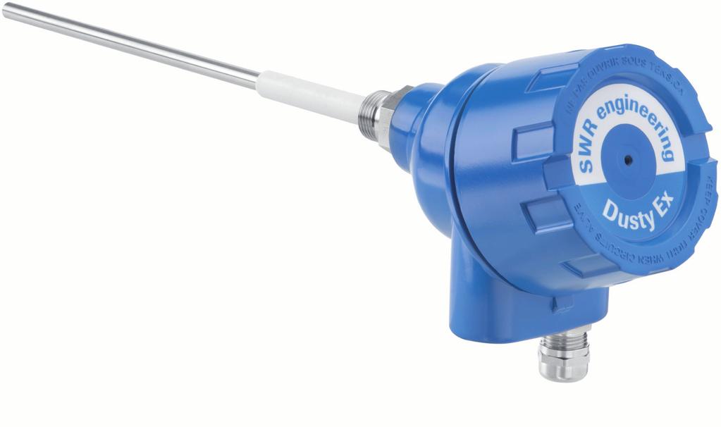
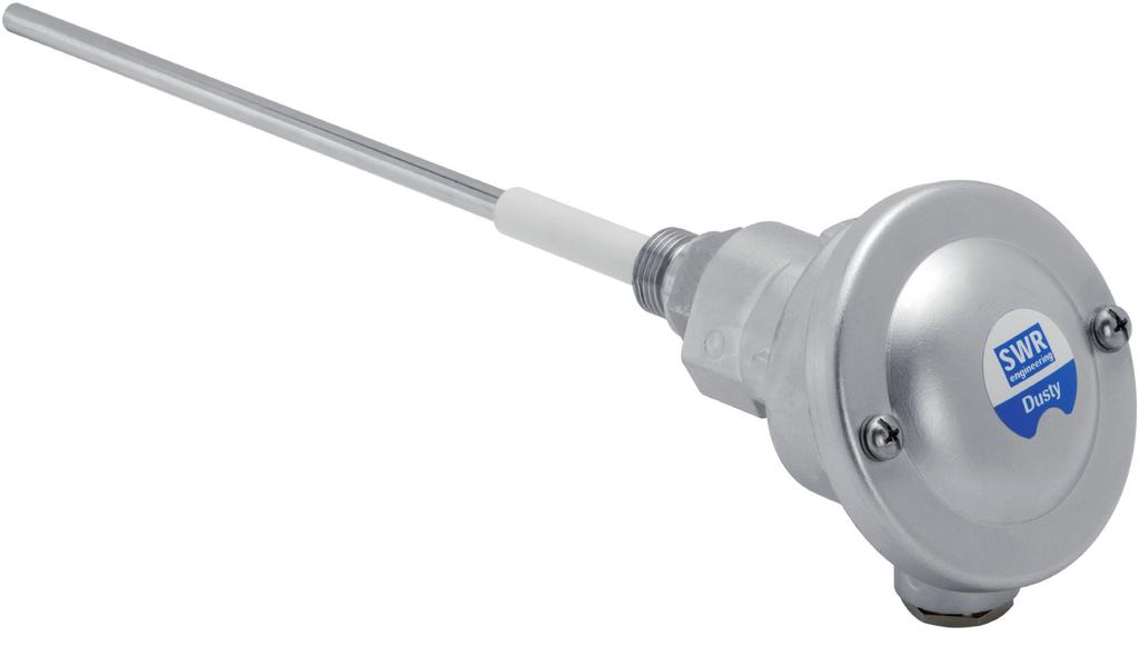
3 1. Introduction 1.1 Safety Dusty requires 24 ±10 % V DC power supply. 24 ±10 % V DC voltage level is considered as safe. DIN Rail Converter requires 24 ±10 % V DC power supply. 24 ±10 % V DC voltage level is considered as safe. Precautions: The duct has to be opened at the installation and the maintenance. Thereby some risks have to be considered: The flow of gas or dust can be hazardous to health. The flow can be inflammable, explosive or toxic. The gas can be hot or under pressure. 1.2 Product Overview The Dusty is a microprocessor-based, pre-adjusted device, equipped with 1 switch for setup, 1 relay output and 3 LED, viewable when the cover is open. The Dusty is designed for filter bag leak detection. It is a compact unit consisting of sensor and control electronics built into an IP 65 enclosure, which has been specifically designed for easy installation and operation. Pre-adjusted alert level is on 25 mg/m³ of organic dust material at 14 m/s air velocity. If the measure of dust is higher than this alert level the relay output will be switched. LEDs on the sensor show the status of measure, alarm output and internal function status. Easy One Button User Interface allows to increase/decrease the alert level, to perform a AutoSetup and to restore factory setting. Optional there is a DIN Rail Converter providing a ma trend signal and replacing the relay output. With the DIN Rail Converter there is a PC software to increase/decrease the alert level, to perform a AutoSetup and to restore factory setting. Optional there is a PC software to change additional parameter (filter time, hold time etc.) of the sensor, to view signal trends and to write protocol files. The Dusty is designed for applications at up to 2 bars and 140 C. As an option the system can also be used in Ex-areas of category 3 (gas + dust). The device is connected to a 4 wire cable in its internal terminal box. 3
4 1.3 How does it work The Dusty works with its proven and reliable tribo-electric technology whereby the interaction of dust particles with the sensor rod causes a small electric charge, when the particles pass or strike by the sensor rod. This small electric charge generates a signal proportional to the dust level even if there is an accumulation of particles on the sensor rod. Experience has shown that this method of sensing dust level in gases offers accurate results with a minimum of maintenance. After start-up the sensor blinks on the LEDs for information purpose: the red LED blinks two times during system check, the orange LED blinks to inform about the actual factor of alert level (threshold). Then the device starts to monitor the dust level and the green LED will blink with a frequency that shows the relation of actual measure against actual alert level: the lower the frequency the lower the measure. If the measure goes higher the frequency goes faster, if the measure is equal or higher than the alert level the green LED stops blinking and the orange LED switches on. If the orange LED is switched on, the relay output is switched to indicate the alarm situation. If the relay is used as normally closed (NC), the sensor is also monitored on power cut. Also any other fail will be alarmed via the relay. With optional DIN Rail Converter the system provides a ma output as a trend of the dust load. There is no need to maintain or set up the DIN Rail Converter and the output signal cannot be calibrated: a current of 4 ma means no dust in the duct, a current of 12 ma means that dust level is equal to alert level (switch-point of relay). Dust concentrations will be indicated linear up to 20 ma. If there is an error found by internal system checks the output is set to 2 ma. The relay output function of the sensor device is replaced by the DIN Rail Converter relay output due to alternative cabling between sensor and DIN Rail Converter. 4
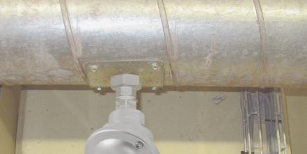
5 2. Installation 2.1 Selecting the Installation Location The best location for installation of the Dusty is in a duct section where the flow has its most even distribution and the flow is as laminar as possible. The optimal position would be in a horizontal or vertical section of the duct. There have to be no bends, valves, dampers or other obstructions in a distance equal to a quintuple of the duct diameter in every direction of flow to the sensor rod. (See figure 1) Fig. 1: Recommended distances to bends (DN = duct diameter) In some applications a compromise has to be made and the sensor will have to be fitted in a position that satisfies the majority of above requirements. The Dusty housing must be attached to metal ductwork so that they will be electrically shielded from interference and be provided with a good grounding. For non-metal ducts, a section of the duct, approx. five diameters in length, should be covered with a metal foil or fine-mesh on the periphery of the duct. 1. The unit shall be installed in a position, where the gas flow passes the sensor rod in a 90 angle. 2. In round cross-section ducts the unit can be installed in any position above the horizontal axis (between 9 and 3 o clock). (See figure 2a) 3. For square cross-section ducts, the unit must be positioned in the middle of the top or in the middle of one of the sides. (See figure 2b) 4. Although the sensor is not affected by vibration, very high vibration levels should be avoided. 5. The units should not be installed in direct sunlight or in areas where the ambient temperature is above 60 C. 5
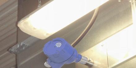
6 6. The sensor rod must not contact the opposite duct wall or any other obstacle inside the duct! In cases of need the sensor rod can be shorten to a minimum length of 70 mm. Be careful not to damage the plastic cap by doing this. The recommended length of the antenna is pipe diameter minus 10 mm. Certainly you have to insure that there will not come up any contact to the pipe, even there will grow any coating inside the pipe. The minimum length of the antenna should be 1/3 of the pipe diameter. A main rule is: the lower the dust concentration the longer the length of the antenna. 7. By monitoring a precipitator it is recommended to look for a sensor position behind the blower. If the sensor is to be used behind an electrostatic precipitator the distance to the precipitator should be a minimum of 20 m. Even so the sensor function is not affected due to vibration, the sensor should not be exposed to high vibration during a long time period. The unit above horizontal axis. Fig. 2a: Round cross-section duct The mounting socket in the middle of the side or in the middle of the top. Fig. 2b: Square cross-section duct 2.2 Installing the Sensor Once the location of the unit has been selected, the R 1/2 male thread is welded on the duct wall. Then the R 1/2 female thread is screwed in until there is a tight connection to the process. Caution: Do not over tight the Dusty with the process, because it could cause damage to the sensor and electronics! Do not open the hexagon socket screw to turn the head of the Dusty, because the cables could be torn off the board. 6
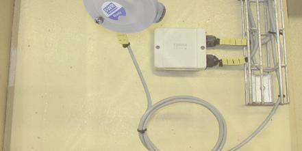
7 + 24 V 0 V RS A RS B NO COM NC Operating Instructions 3. Electrical Connection The Dusty is fit out with an internal wiring box, providing the plugs for different options: Plug number Signal name 1 V+ (24 V DC) 2 V- (0 V) 3 RS A 4 RS B 5 Relay NO 6 Relay C 7 Relay NC 3.1 Dusty as Stand Alone Dust Switch If used as a stand alone dust switch there are 4 wires to be installed. Plug number Dusty 1 V+ (24 V DC) 2 V- (0 V) 5 Relay NO 6 Relay C 7 Relay NC (alternative) 3.2 Dusty with DIN Rail Converter If used with the DIN Rail Converter the 4 cable wiring can still be used but has to be altered on the plugs: If the DIN Rail Converter is used the relay output of the sensor is replaced by the relay output of the DIN Rail Converter. Sensor + 24 V GND A B Up to 300 m at sufficient wire cross section DIN Rail Converter 16 (+ 24 V) 15 (GND) 14 (A) 13 (B) For long distances and noisy environment shielded cables and twisted pair wiring is recommended! 7
8 3.3 Dusty with M12 plug SWR Dusty with M12 plug / socket Plug No. Signal 1 V (+24 V DC) 2 V (0 V) 3 ModBus A 4 ModBus B 5 Relay NO 6 Relay COM 7 Relay NC 8
9 3.4 DIN Rail Converter 1 Current output 2 Current output 3 Input ma ma power supply 0 V DC 5 Not reserved 6 Alarm relay 7 Alarm relay 8 NC (Opener) C Input power supply + 24 V DC Alarm relay NO (Closer) Not reserved 10 Not reserved 11 RS interface data B 13 Sensor connection 14 Sensor connection 15 Sensor connection 16 RS 485 RS 485 Power supply 0 V Data B Data A RS 485- interface data A Sensor connection Power supply + 24 V 9
10 3.5 Use in Ex Hazardous Areas Marking DustEx: II 3D Ex ia/tc IIIC 120 C - Equipment group: 2 - Equipment category: 3 - For explosive mixtures of air and combustible dusts - IP-code 66 - Permitted process temperature -20 bis 120 C Marking GasEx: II 3G Ex ia/d IIC T4 The sensor is not allowed to be used in areas of class IIC, in case of expected, intense charging processes. - Equipment group: 2 - Equipment category: 3 - For explosive mixtures of air and combustible gases - IP-code 66 - Permitted process temperature -20 bis 120 C Hazardous Area DustEx-Zone 22 GasEx-Zone 2 DustEx-Zone 22 GasEx-Zone 2 Non-hazardous Area Tmax = 120 C Tmax = 60 C 10
11 ,5 81,8 14,1 Operating Instructions 4. Dimensions 4.1 Sensor ø90 S 27 G 1/2 81,8 66,0 ø8 Fig. 3: Dimensions of Dusty 4.2 DIN Rail Converter Fig. 4: Dimensions of DIN Rail Converter 11
12 5. Operation The sensor measures the dust level in a gas flow by collecting tribo-electric energy by dust particles hitting or passing near by the probe. After start-up the sensor blinks on the LEDs for information purpose: the red LED blinks to inform about the actual ModBus address, the orange LED blinks to inform about the actual factor of alert level and then the green LED starts to blink with a frequency that shows the relation of actual measure against actual threshold: the lower the frequency the lower the measure. If the measure is high the frequency goes faster, if the measure is equal or higher than the alert level the LED stops blinking. Measuring levels higher than the alert level will be indicated by the yellow LED in ON status. The relay contact works as an alarm output. If the measured dust level is higher than the alert level, the relay is activated (accordingly to the yellow LED). Blinking of the red LED indicates an internal error. 5.1 Alert Level The alert level is factory pre-adjusted to a level of approx. 25 mg/m³ of organic dust material at 14 m/s of air velocity. This switching level is measured at the factory dust channel and is no absolute level for customers dust amount. To adjust to customer s desire there is one button to increase or decrease the switching level by simply changing a multiplier factor. To change the factor see chapter 5.2 One Button Operation. An internal measure value is pre-calibrated to 5 mg/m³ in factory test duct A multiplier factor is pre-set to 5 Alert level (threshold) is calculated with [ factor * internal measure value ] = [ 5 * 5 mg/m³ ] Alert level = 25 mg/m³ Changing the factor to 4 means changing to alert level = 4*5 mg/m³ = 20 mg/m³ Changing the factor to 10 means changing to alert level = 10*5 mg /m³ = 50 mg/m³ Maximum factor is 30, maximum alert level = 30*5 mg/m³ = 150 mg/m³ Higher dust levels can be adjusted with AutoSetup function. 5.2 One Button Operation Button S1 Pressing the button S1 will start a sequence of command options by blinking patterns. To get the desired function just RELEASE the button while it blinks accordingly! 12
13 1. Command sequence: Information only! Release the button while all three LEDs are blinking up to 5 times in common: the red LED will blink out the sensors address and the yellow LED will blink accordingly to the actual factor. 2. Command sequence: Setup of factor: Release the button while only the yellow LED is blinking: the factor is increased/decreased to the count of blinks of the yellow LED. Count the blinks to set new multiplier factor (max. 30 times) 3. Command sequence: AutoSetup! After a countdown of all 3 LEDs the LEDs are blinking up to 5 times in common: release the button while blinking of the LEDs. Sensor will enter AutoSetup mode (see chapter 5.3 for details) 4. Command sequence: Restore the factory setting: After a second countdown of all 3 LEDs the LEDs are blinking up to 5 times in common again: release the button while blinking of the LEDs to restore the factory pre-set for alert level (threshold) and factor. The LEDs will go to OFF status after the last sequence. No changes are made after the LEDs are OFF. 5.3 AutoSetup To set an individual alert level you can use the AutoSetup procedure. AutoSetup will count the actual level of dust in the duct and will store this value as internal measure value multiplied by factor as the new alert level (see chapter 5.1 alert level). To use AutoSetup procedure, make sure that the process is running with a normal dust flow rate. Ensure that the device is powered on for at least 10 minutes. Open the cover of the device and initiate AutoSetup by pressing the button and release it accordingly to the description in chapter 5.2. The LEDs will flash consecutively and the sensor will look for peaks in the measurement value to keep the highest possible measurement value during the process of AutoSetup The highest peak will be the internal measure value that will be multiplied by the factor to calculate the new alert level. AutoSetup procedure takes 5 minutes to be completed, the LEDs stops flashing, green LED goes back into blinking state to indicate that the device is ready to use again. AutoSetup procedure can be cancelled by pressing the button S1 during AutoSetup procedure. No changes will be made when AutoSetup is cancelled. 5.4 DIN Rail Converter The DIN Rail Converter communicates with the sensor via digital bus line, so it needs to be wired in an alternative way. If installed it takes the alert level value form the sensor as 12 ma point and zero as 4 ma point to calculate a linear function for the measure value. The measured value will be given as a current output value according to this linear function. So there is no need to set up any parameter on the DIN Rail Converter. If the alert level is changed by changing the factor or by changing the alert value due to AutoSetup procedure the gradient of the function automatically will be adjusted. The relay output of the DIN Rail Converter will show exactly the same behaviour as the relay output of the sensor. There is a simple software to use the DIN Rail Converter and its digital communication to the sensor to achieve a remote control to the sensor, e.g. if the sensor is in an inconveniently installation situation. 13
.")
14 5.5 PC Software If the DIN Rail Converter is used there is a PC Software to replace the access to the setup button and to set the function of the relay. The software is easy to use and self explaining. On the register card info you have to select your COM port (port numbers 1 to 10). You can alter the alert value and the alert factor as well as the AutoSetup time by entering and sending new values. By doing this you will lose the factory settings, because values sent over serial communication will also be saved as factory defaults. 14

15 You can initiate an AutoSetup procedure by pressing the button Find TRH. You can choose the following options by pressing the appropriate ON/OFF button: Fix AS Time: if hooked the given AutoSetup time is used to measure the dust level during AutoSetup procedure. If un-hooked the AutoSetup procedure is extended by the given AutoSetup time if the measure of dust shows a peak higher than the last highest peak. S1 Active: if un-hooked the hardware button S1 on the device is de-activated. This is for security purpose to avoid unauthorised change on the device. DIN Rail Relay NC: if hooked the relay on the DIN Rail Converter is NC (normally closed), otherwise it is NO (normally open). You can read out the serial number, the DB-version and the FW-version of the sensor as well as the actual measure value, the status of the alarm output (dust > TRH) and eventually running AutoSetup procedure. In the trend window you can see the actual reading of dust level compared to threshold or the status of the alarm output. 15

16 6. Maintenance For the maintenance the unit has to be removed from the process so that the sensor probe and the sensor insulation (white sleeve) can be cleaned. Hereby it s possible to prevent deposit bridges between the sensor rod and the duct wall which could induce to a function failure or short-circuit. If particles in the gas are sticky and tend to build up, the cleaning needs to be done more often. Inside the enclosure maintenance is not needed. 7. Troubleshooting 7.1 No Switching of the Output Signals 1. Check the power and the connection of the contacts. 2. Check if green LED is blinking or orange LED is on: determines the relay stat! 3. Check if red LED is blinking more than one per second: count the flashes as error code! If the sensor is not giving any output signals after the checks 1, 2 and 3, please contact: our branch offices OR our distributors OR SWR engineering Messtechnik GmbH. 7.2 No Sensor Response after AutoSetup 1. Check if the normal process is going on and if there were normal operation conditions during the AutoSetup. 2. Check the blinking frequency of green LED. 3. Check if there is no short circuit there is no contact between the sensor probe and the duct wall. the gas is not condensing (because of build up). the dust is not sticky: so there is no build up on the sensor base which could induce to a bridge between the sensor probe and the duct wall. This instrument conforms to the following standards: Product standard - electrical equipment for measurement, control and laboratory use - EMC requirement Reference standard EN Publication year (1997) amendment(s) A1 (1998), A2 (2001), A3 (2003) 16
17 8. Technical Data Sensor Measurement objects Solid particles in a gas flow Particle size 0.3 µm or larger Measurement range From 0.1 mg/m 3 Range setup Pre-adjusted and automatic Process temperature Max. 140 C Ambient temperature C Pressure Max. 2 bar Gas velocity Min. 4 m/s Humidity 95 % RH (non-condensing) Measurement principle Tribo-electricity (electrostatic detection) Damping time 1 s Output signals 1 relay output (NO / NC) Alarm settings Alert - dust level > threshold Sensor rod Total length: 260 mm, length of stainless steel rod: approx. 194 mm Enclosure Aluminium Using in Ex-zones Cat. 3 G/D (zone 2 gas / zone 22 dust) Protection category IP 65 Power supply 24 ± 10 % V DC Power consumption 1 W Electrical connections Internal connection box Cable (power + signal) 4 wires Process connection G 1/2 male thread Weight Approx. 0.7 kg DIN Rail Converter Power Supply 24 ± 10 % V DC Power consumption 5 W / 24 VA Protection category IP 40 according to EN Operating temperature C Dimensions 22,55 x 90 x 118,8 (W x H x D) Weight Approx. 350 g Cable cross section mm² [AWG 24-14] Current output signal ma, load < 500 W Alarm output Error output Relay with toggle switch - max. 250 V AC, 1 A Digital interface ModBus (RS 485) Data protection Flash memory SWR engineering Messtechnik GmbH Gutedelstraße Schliengen (Germany) Fon Fax All rights reserved. EN 15/09/
SolidFlow. Monitoring of Solids. Product Information. SWR engineering Messtechnik GmbH
 EN SolidFlow Product Information Monitoring of Solids SWR engineering Messtechnik GmbH Using SolidFlow is a sensor especially developed for measuring the flow rate of solids conveyed in metallic ducts.
LTX RF LEVEL SENSOR. Instruction Manual
 LTX RF LEVEL SENSOR Instruction Manual FOR MODELS LTX01, LTX02, LTX05 Intempco Document No: LTX - M01 Rev. 1 Issue Date: April 2005 LTX01 RF LEVEL SENSOR USER MANUAL Software Rev : Rev. Date : June 2004
General Specifications
 General Specifications Model DT450G Dust Monitor GENERAL Powder is used in many industries including ceramics,cement, chemicals, pharmaceutical and food. In their processes, powder is collected in order
1.0 Features and Description
 1.0 Features and Description The is an intelligent actuator designed for precise control of quarter turn valves and dampers. Using stepper motor technology, the SmartStep proportionally positions valves
DSL-240 MkIII Single Pass Dust Monitor Measures mg/m 3 using DDP
 Ideal for monitoring dust levels in the exhaust gas of industrial combustion or air filtration processes. Innovative Dynamic Detection Principle (DDP) measurement technique Immune to gradual reductions
Pneumatic control unit for decentralized automation of ELEMENT process valves
 890 Pneumatic control unit for decentralized automation of ELEMENT process valves Type 890 can be combined with... Compact design Integrated pilot valve with manual override Integrated control air routing
RS485 MODBUS Card. User Manual. Before you start to install this card, please read this User Manual carefully
 Before you start to install this card, please read this User Manual carefully Thanks for choosing MPI Series RS485 MODBUS Card which is a highly reliable product made by with its innovative design and
INLINE Flow sensor for hazardous area II 1 G/D - II 2 D - II 3 GD - I M1
 INLINE Flow sensor for hazardous area II G/D - II D - II GD - I M Type SE0 Ex can be combined with... Flow meter with NAMUR or NPN/PNP output signal Mounting, dismounting of electronics by a Quarter-Turn
Intelligent Positioner
 Intelligent Positioner Construction The GEMÜ 1 µpos is a digital electro-pneumatic positioner for process valve control. Designed for simple, safe and quick use with valves with strokes < mm. The positioner,
DIAMOND POINT VIBRATING PROBES
 DIAMOND POINT VIBRATING PROBES DP130 DP120 DP140 DP150 Instruction Manual Third revision, April 2016 Hycontrol Ltd., Larchwood House, Orchard Street, Redditch, Worcestershire, B98 7DP, U.K. Tel: + 44 (0)1527
CVR-625. Compact Vibrating Rod Instruction Manual
 CVR-625 Compact Vibrating Rod Instruction Manual BinMaster: Division of Garner Industries 7201 N. 98th St., Lincoln, NE 68507 402-434-9102 email: info@binmaster.com www.binmaster.com OPERATING INSTRUCTIONS
1. INTRODUCTION SYSTEM DESCRIPTION Front Panel CONNECTION AND OPERATION TROUBLESHOOTING...8
 Contents : 1. INTRODUCTION...1 2. IMPORTANT SAFETY INSTRUCTIONS...2 3. SYSTEM DESCRIPTION...4 3.1 Front Panel...4 4. CONNECTION AND OPERATION...6 5. TROUBLESHOOTING...8 6. MAINTENANCE...9 6.1 Operation...9
INTECH Micro 2300-RTD6
 INTECH Micro 2300-RTD6 6 Channel RTD Input Station Overview. The Intech Micro 2300 Series is a system of modular I/O Remote Stations, that add an even lower cost option to Intech s already extensive intelligent
Inductive conductivity meter
 Inductive conductivity meter Type 8228 can be combined with... Configurable outputs: up to 2 transistor and up to 2 analog 4... 20 ma outputs Removable backlighted display Simulation of process values
EGQ 212: Duct transducer, CO 2 and temperature
 Product data sheet 7.0 EGQ : Duct transducer, CO and temperature How energy efficiency is improved Measuring the CO concentration and temperature for energy-efficient, demand-controlled regulation of the
Electromagnetic Flow Monitor magphant
 Technical Information TI 036D/06/en No. 50078457 Electromagnetic Flow Monitor magphant Monitoring and measurement Flow monitoring with selectable limit values (relay output) Flow measurement via 4...20
Inductive conductivity meter
 Inductive conductivity meter CIP version Type 8228 can be combined with... Standard version Perfect for concentrated liquids and wide conductivity range Pre-parameterized versions available for direct
User Manual Rittal PMC UPS 6kVA
 User Manual Rittal PMC UPS 6kVA Germany Rittal GmbH & Co. KG Auf dem Stützelberg D-35745 Herborn Tel.: ++49-27 72-5 05-0 Fax: ++49-27 72-5 05-23 19 Internet: www.rittal.de 26 Contents 1. Introduction...
BT403. A Geno Technology, Inc. (USA) brand name. BT-300 Power Supply. Cat. No. BT
 brand name. BT-300 Power Supply. Cat. No. BT") BT403 A Geno Technology, Inc. (USA) brand name BT-300 Power Supply Cat. No. BT403 1-800-628-7730 1-314-991-6034 info@btlabsystems.com WARNING... 3 SAFETY INFORMATION... 3 ENVIRONMENTAL CONDITIONS... 4
BT403 A Geno Technology, Inc. (USA) brand name BT-300 Power Supply Cat. No. BT403 1-800-628-7730 1-314-991-6034 info@btlabsystems.com WARNING... 3 SAFETY INFORMATION... 3 ENVIRONMENTAL CONDITIONS... 4
Continental Hydraulics Installation Manual CEM-AA-A
 Continental Hydraulics Installation Manual CEM-AA-A Description: This power amplifier drives either single or dual solenoid proportional valve coils up to 2.6A. It is suitable to control current to proportional
LDX-U20 is a microprocessor controlled DC-UPS rated 20 A usable in 12 V or 24 V systems.
 LDX-U20 is a microprocessor controlled DC-UPS rated 20 A usable in 12 V or 24 V systems. LDX-U20 monitors the voltage supplied by a DC source and in case of power failure a backup battery is connected
Uninterruptible Power System
 USER'S MANUAL Emergency Backup Power Supply For Use With Computer Loads Only Power Surge/Noise Protection Intelligent Auto-Shutdown Software Internet Line Protection Cost Efficiency AVR Protection Compact
ECONOMISER SERIES E2T USER MANUAL
 TURBO S.R.L. Electronic Control Systems for Dust Collectors e-mail: info@turbocontrols.it web: www.turbocontrols.it TEL. ++39 (0)362 574024 FAX ++39 (0)362 574092 ECONOMISER SERIES E2T USER MANUAL 24/06/2014
Operating Instructions. Pneumatic Control Valve Low Temperature. Type Series GS3
 Operating Instructions Pneumatic Control Valve Low Temperature Type 8026 Series GS3 With: Digital Positioner Type 8048 Electro-pneumatic Positioner Type 8047 Pneumatic Positioner Type 8047 Version: 03/2006
Uninterruptible Power System
 USER'S MANUAL Emergency Backup Power Supply For Use With Computer Loads Only Power Surge/Noise Protection Intelligent Auto-Shutdown Software Internet Line Protection Cost Efficiency UPS AVR Protection
See «Overview of types»
 echnical data sheet SHA-.. Multifunctional linear actuators for adjusting air dampers and slide valves in ventilation and air conditioning systems in buildings For air dampers up to approx. 3 m Actuating
Superstatic 440. Static Heat- and Cooling Meter. Application
 Superstatic 440 Static Heat- and Cooling Meter Application Design The Superstatic 440 is a static heat- and cooling meter according to standard EN1434 class 2 based on the fluid oscillation principle,
JUMO dtrans p20. Process pressure transmitter. Type Brief description. Key features. Block diagram
 Data Sheet 403025 Page 1/10 JUMO dtrans p20 Process pressure transmitter Brief description The JUMO dtrans p20 pressure transmitter with HART interface combines maximum precision with easy operation. It
INSTRUCTION MANUAL_1219_ENGLISH SUPER ELF X3. Operating Instructions for DORNIER looms. Robustness Reliability Quality Productivity Versatility
 INSTRUCTION MANUAL_1219_ENGLISH SUPER ELF X3 Operating Instructions for DORNIER looms Robustness Reliability Quality Productivity Versatility WARNING! - Condensation could form on the Weft Feeder when
Observe all necessary safety precautions when controlling the soft starter remotely. Alert personnel that machinery may start without warning.
 Introduction OPERATING INSTRUCTIONS: MCD REMOTE OPERATOR Order Codes: 175G94 (for MCD 2) 175G361 + 175G9 (for MCD 5) 175G361 (for MCD 3) 1. Introduction 1.1. Important User Information Observe all necessary
PCS-250 System Installation Instructions
 PCS-250 System Installation Instructions Made in the USA PCS-250 System Specifications Page 1 TCU-250: Control PS-1000: Power Supply (optional) Input: 24VDC, 250mA Input Voltage: 110-240VAC Relay Outputs:
Adjustable PT100 Bearing Temperature Sensor with ½ NPT Conduit Entry
 Adjustable PT100 Bearing Temperature Sensor with ½ NPT Conduit Entry Hot bearing WARNING device, for use in hazardous areas Installation guide PT100V3C Bearing Temperature Sensor With Grease nipple 1/2
SMARTLINK METER. Digital Self-checking Thermal Mass Flow Meter
 Flow Control Components - SMARTLINK METER 10-30.9-1 SMARTLINK METER Digital Self-checking Thermal Mass Flow Meter Precise, repeatable mass flow measurement for fuel, air and combustion streams Displays
Inlet Controller TC5-ITA USER'S MANUAL. M rev. 02 K rev. 00
 Inlet Controller TC5-ITA USER'S MANUAL M 890-00047 rev. 02 K 895-00458 rev. 00 TABLE OF CONTENTS PRECAUTIONS... 3 FEATURES... 4 LOCATION OF THE CONTROLS... 5 Status Leds...5 Internal Switches...6 INSTALLATION
ExBin-P Pressure switches 5 Pa Pa
 ExBin-P Pressure switches 5 Pa... 5.000 Pa Electrical, explosion-proof binary pressure / differential pressure switches 5 Pa...100 Pa with adjustable switch activation delay 24 VAC/DC supply voltage, potential
DensFlow D. Superior with Solids. Flow measurement for densphase conveying. Operating Instructions
 EN Operating Instructions DensFlow D Flow measurement for densphase conveying SWR engineering Messtechnik GmbH PART OF THE ENVIRONNEMENT S.A GROUP ontents Page 1. System overview.............................................
Simply a question of better measurement
 Simply a question of better measurement Flow sensors for air and gases SCHMIDT Flow Sensors Solutions for measuring technology in practice SCHMIDT Technology is a specialist in the development and production
better measurement Simply a question of
 Simply a question of better measurement SCHMIDT Flow Sensor SS 2.415 and SS 2.515 The tried and tested measurement experts for the monitoring of laminar flows extremely precise and quickly installed Industrial
Sentronic PLUS 614 Series
 Sentronic PLUS 64 Series Proportional Technology www.asco.com PRESSURE CONTROL: 64 SERIES SENTRONIC PLUS Sentronic PLUS Sentronic PLUS is a digitally operated pressure regulator valve. This valve accurately
FVC2100/2200 TEK-AIR TECHNICAL PRODUCT DATA SHEET FUME HOOD FACE VELOCITY MONITOR AND CONTROLLER. Application. General Description
 TEK-AIR TECHNICAL PRODUCT DATA SHEET FVC2100/2200 FUME HOOD FACE VELOCITY MONITOR AND CONTROLLER MODEL 2100: Constant face velocity, variable volume MODEL 2200: Constant face velocity, variable volume
Technical Datasheet. Compact DC Energy Meter. Multi-Function DC Energy Meter
 Preliminary Datasheet Technical Datasheet Compact DC Energy Meter RISH EM DC series is specially designed to measure, display and communicate DC Voltage, Current, Power and Energy to monitor and control
DSL-220 MkIII Single Pass Opacity Monitor Measures 0-100% Opacity
 Ideal for monitoring opacity and smoke levels in the exhaust gas of industrial combustion or air filtration processes. In situ measurement directly in exhaust gas flow using the widely accepted light transmission
Options guide. Electromagnetic flowmeters. M9xx
 Options guide Electromagnetic flowmeters M9xx Ordering codes Model Description M 910 -V0 0 0 0 DN50 PN16 Example Sensor M Basic Ex Ex certified (remote version only) Transmitter 910E Economic version 910
Application. Tek-Air Systems, Inc. 41 Eagle Road Danbury, CT (203) FAX: (203) SALES FAX: (203)
 FAX: (203) SALES FAX: (203)") TEK-AIR TECHNICAL PRODUCT DATA SHEET FVC2600 SASH SENSING VAV FUME HOOD SYSTEM MODEL 2600: Variable volume control based on sash position utilizes microprocessor based electronics and linear air control
TEK-AIR TECHNICAL PRODUCT DATA SHEET FVC2600 SASH SENSING VAV FUME HOOD SYSTEM MODEL 2600: Variable volume control based on sash position utilizes microprocessor based electronics and linear air control
Operating Instructions. VEGASWING 61, 63 with oscillator SW E60N (EX)
") Operating Instructions VEGASWING 61, 63 with oscillator SW E60N (EX) Contents Contents Safety information... 2 Note Ex area... 2 1 Product description... 3 2 Function and application... 4 2.1 Principle
Operating Instructions VEGASWING 61, 63 with oscillator SW E60N (EX) Contents Contents Safety information... 2 Note Ex area... 2 1 Product description... 3 2 Function and application... 4 2.1 Principle
Digital Pressure Regulator Sentronic PLUS Series 614
 Digital Pressure Regulator Sentronic PLUS Series 14 Installation manual IM149-/R01 CONTENTS 1. Description... 1.1 Catalogue number... 1. Operating elements...4 1. Operating modes...4. Electrical connection...5.
Data Sheet SCHISCHEK EXCOS-P. Pressure sensor 20 Pa Pa. Supplied by. .com. Call us on +44 (0)
") Data Sheet SCHISCHEK EXCOS-P Pressure sensor 20 Pa... 7.500 Pa Supplied by.com Call us on +44 (0)118 916 9420 Email info@247able.com ExCos-P Pressure sensor 20 Pa... 7.500 Pa Electrical, explosion-proof
Data Sheet SCHISCHEK EXCOS-P Pressure sensor 20 Pa... 7.500 Pa Supplied by.com Call us on +44 (0)118 916 9420 Email info@247able.com ExCos-P Pressure sensor 20 Pa... 7.500 Pa Electrical, explosion-proof
Product specification
 Product specification Features Non-contacting displacement measurement based on the eddy-current principle System length: 5 m or 10 m with ATE approval Temperature range displacement sensor: -55 C +180
SMARTLINK METER. Digital Self-checking Thermal Mass Flow Meter
 Flow Control Components - SMARTLINK METER 10-30.9-1 SMARTLINK METER Digital Self-checking Thermal Mass Flow Meter Precise, repeatable mass flow measurement for fuel, air and combustion streams Displays
Operating Instructions for Pressure Transmitter with Digital Display. Model: PDA
 Operating Instructions for Pressure Transmitter with Digital Display Model: PDA 1. Contents 1. Contents... 2 2. Note... 3 3. Instrument Inspection... 3 4. Operating Principle... 3 5. Regulation Use...
Match 19" GE Digital Energy. Uninterruptible Power Supply VA. Technology for the Digital World. Match 19" UPS.
 Match 19" Uninterruptible Power Supply 700-1500 VA Manufactured by: General Electric Company Telephone +41 (0)91 / 850 51 51 CH 6595 Riazzino (Locarno) Fax +41 (0)91 / 850 51 44 Switzerland Website www.gedigitalenergy.com
OPERATING MANUAL. High-efficiency AR Series. Stepping motor and driver package. Introduction. Applicable motor. Before use
 HM-08 OPERATING MANUAL Stepping motor and driver package High-efficiency AR Series DC power input Built-in Controller Type (RS-8 communication function) Driver Introduction Before use Only qualified personnel
Inlet Controller SB3500 USER'S MANUAL
 Inlet Controller USER'S MANUAL NOTICE Every effort has been made to ensure that this manual is complete, accurate and up-to-date. The information contained in it is however subject to change without notice
MULTI FUNCTIONAL COUNT CHECKER MODEL Poka Patrol CNA-4mk3
 MULTI FUNCTIONAL COUNT CHECKER MODEL Poka Patrol CNA-4mk3 OPERATING INSTRUCTION Poka Patrol CNA-4mk3 Poka Patrol CNA-4mk3 To use this product properly and safely, please read this manual carefully before
Product manual Oil Streak Sensor INTRODUCTION CONSTRUCTION. Master Sensor
 Product manual Oil Streak Sensor INTRODUCTION Oil streak sensors are designed to detect traces of oil travelling through air tubes, down to flows as low as 5mm 3 /min. The product utilizes a master and
Operating Instructions. Angle Seat Control Valve. Type 7020
 Operating Instructions Angle Seat Control Valve Type 7020 With: Digital Positioner Type 8048 Electro-pneumatic Positioner Type 8047 Pneumatic Positioner Type 8047 Version: 02/2006 Manual-7020e.doc Art.-No:
Flow measurement FlexFlow PF20H Hygienic flow sensor
 Product highlights Parallel measurement of flow and temperature Flow measurement independent of the mounting position Large measuring range up to 400 cm/s Measurement at high media temperatures up to 125
Manual Electronic Identification Systems BIS Read/Write Heads C3-slk_716464_E_1110.p65 Deutsch bitte wenden!
 C3-slk_716464_E_1110.p65 1 Manual Electronic Identification Systems BIS s Deutsch bitte wenden! 2 No. 716 464 D/E Edition 1110 Subject to modification. Replaces edition 1104. Balluff GmbH Schurwaldstrasse
Electronic Circuit Breaker ESS20-0..
 Electronic Circuit Breaker ES-0.. Description Electronic circuit breaker type ES-0.. is designed to ensure selective disconnection of individual loads in systems which are powered by a DC 4 V switch-mode
MB A 12V/24V DC PROGRAMMABLE DUAL BATTERY ISOLATOR
 MB-3688 120A 12V/24V DC PROGRAMMABLE DUAL BATTERY ISOLATOR User Manual Warning and Precautions MB-3688 is built with corrosion resistant material and the main electronic assembly is well sealed inside
Product specification
 Product specification 4 mm Measuring Range Features Non-contacting displacement measurement based on the eddy-current principle System length: 5 m or 10 m with ATE approval Temperature range displacement
Temperature Controller (Heat Pumps)
") 3 345 Temperature Controller (Heat Pumps) For comfort control in HVAC systems RWD31 RWD41 Stand-alone electronic temperature controller Four 2-position (On/Off) outputs Easy adjustment of parameters via
3 345 Temperature Controller (Heat Pumps) For comfort control in HVAC systems RWD31 RWD41 Stand-alone electronic temperature controller Four 2-position (On/Off) outputs Easy adjustment of parameters via
Operating instructions Flow monitors SI6000 SI6100 SI /00 06/2011
 Operating instructions Flow monitors SI6000 SI6100 SI6200 706053/00 06/2011 Contents 1 Safety instructions... 3 2 Functions and features... 4 2.1 Application area... 4 2.2 Operating principle flow monitoring...
HERZ Motorised Actuator
 HERZ Motorised Actuator Data sheet for HVACT Issue 1017 Dimensions Models HVACT24-01 HVACT230-01 HERZ Motor Valve Drive, Floating 3-point, M28 x 1.5, 24 V, 50 Hz actuating force 140 N, operating voltage
Continuous level sensor NSK
 SENSORS FOR FOOD AND BIOPHARMA. Product Information NSK-157, -357, -358 FOOD Continuous level sensor NSK Application Continuous level monitoring in metallic vessels up to 3 m in height Ideal for highly
Combined Ventilation Controller RVWS-T-224HA
 Combined Ventilation Controller RVWS-T-224HA 8-stage Control for Power/Natural Applications 2 variable speed stages, 2 curtain winch stages, 2 fixed speed ventilation stages, 1 thermo/mister cycle stage
Paddle-wheel flow controller with optical principle for On/Off control
 Paddle-wheel flow controller with optical principle for On/Off control Type 8039 can be combined with... Indication, monitoring, transmitting and On/Off control in one device. Programmable s (transistor
EM DC Multi-Function DC Energy Meter
 Analogue Meters With Moving - Iron Movement EM DC Compact DC Energy Meter Ziegler EM DC series is specially designed to measure, display and communicate DC Voltage, Current, Power and Energy to monitor
On Line UPS. LUC 1000E / LUC 2000E / LUC 3000E User Manual
 On Line UPS LUC 1000E / LUC 2000E / LUC 3000E User Manual Save This Manual Please read this manual carefully prior to storage, installation, wiring, operation and maintenance of the UPS. This manual contains
VALVE CONTROLLERS Controllers for Dust Extr 2010 / 2011 action Technology
 VALVE CONTROLLERS Controllers for Dust Extraction 2010 Technology / 2011 Valve controllers for all cases HESCH has the skills and technology to tackle any control task for dedusting of filter and dust
QUADSCAN User s Guide Door Mounted Presence sensor
 QUADSCAN User s Guide Door Mounted Presence sensor DESCRIPTION 6 7 8 9 0. housing. clip. main connector. DIP-switch. range adjustment screw 6. receiver 7. end cap 8. clip with angle adjustment screw 9.
Example of Combining Different Types of Heater Control. Heater control. Temperature Controller
 Technical Guide for Power s CSM_Power_s_TG_E_5_1 Overview of Power s Example of Combining Different Types of Heater Control Heater control Manual G32X-V2K E5@ series Current output Current output Voltage
JUMO dtrans p20 DELTA
 Data Sheet 403022 Page 1/9 JUMO dtrans p20 DELTA Differential pressure transmitter Brief description The JUMO dtrans p20 DELTA differential pressure transmitter with HART interface combines maximum precision
Begin to Use The New ESC: Before use the new ESC please carefully check every connections are correct or not. Yellow motor wire B Blue motor wire A
 HIMOTO ZTW Brushless Electronic Speed Control for car or truck Thank you for purchasing ZTW Brushless Electronic Speed Controller(ESC). The ZTW electronic speed control (ESC) is specifically designed for
CLA-VAL e-drive-34. User Manual. Motorised Pilots. CLA-VAL Europe LIN072UE - 04/16
 User Manual CLA-VAL Europe www.cla-val.ch cla-val@cla-val.ch 1 - LIN072UE - 04/16 Table of Contents 1 Introduction... 3 1.1 Precautions Before Starting... 3 1.2 Troubleshooting... 3 1.3 General Disclaimer...
Operating instructions Flow monitors SI5000 SI / / 2007
 Operating instructions Flow monitors SI5000 SI5001 704056 / 01 06 / 2007 Contents 1 Safety instructions... 3 2 Functions and features... 4 2.1 Application area... 4 2.2 Operating principle flow monitoring...
The Battery is a client module in the Cabinet Control. It is a backup/ups module which
 LFC7530 Product Guide Battery The Battery is a client module in the Cabinet Control. It is a backup/ups module which is used for supplying other modules with emergency power in the event of power failure.
User Manual Solar Charge Controller 3KW
 User Manual Solar Charge Controller 3KW Version: 1.3 CONTENTS 1 ABOUT THIS MANUAL... 1 1.1 Purpose... 1 1.2 Scope... 1 1.3 SAFETY INSTRUCTIONS... 1 2 INTRODUCTION... 2 2.1 Features... 2 2.2 Product Overview...
RVP-R- VAV controller. In explosion-proof version
 VAV controller In explosion-proof version RVP-R- SMAY LLC / 29 Ciep³ownicza St. / 31-587 Cracow / Poland tel. +48 12 378 18 00 / fax. +48 12 378 18 88 / e-mail: info@smay.eu Intended use VAV control units
Temperature Controller. TC5+2V4SA Plus USER'S MANUAL
 Temperature Controller TC5+2V4SA Plus USER'S MANUAL NOTICE Every effort has been made to ensure that this manual is complete, accurate and up-to-date. The information contained in it is however subject
CAN-Translator. User s guide
 User s guide The interface translating CAN-bus information USER GUIDE CAN-TRANSLATOR DEVICE DESCRIPTION Button (searching) - the button, that starts car searching mode or enables LED diode flashing (which
A and B Series Sensors for Humidity and Temperature for industrial applications from C and up to 25 bar
 Galltec Mess- und Regeltechnik GmbH MELA Sensortechnik GmbH Sensors for Humidity and Temperature for industrial applications from -80...00 C and up to 5 bar AK... with SVKA.0E... duct version up to 150
Technical Datasheet. Multi-channel support RTC with Data Storage RS485 Output Alarming & Protection Onsite Programmable Load Profile Analysis
 Preliminary Datasheet Technical Datasheet Compact DC Energy Meter RISH EM DC series is specially designed to measure, display and communicate DC Voltage, Current, Power and Energy to monitor and control
INSERTION flowmeter with paddle wheel, ELEMENT design
 INSERTION flowmeter with paddle wheel, design Up to PN, size of measurement pipes: DN to DN400 Configurable outputs: one or two transistor output(s) and single or dual 4... ma analog output(s) Removable
NANOPAC-300 & 500 Power Supply. Instruction manual NANOPAC-300 & NANOPAC-500
 NANOPAC-300 & 500 Power Supply Instruction manual NANOPAC-300 & NANOPAC-500 Version 01C Feb 5th, 2014 1 Packing list NANOPAC-300 or 500-1x NANOPAC-300 Power Supply or NANOPAC-500-1x Power Cord - 1x Instruction
A419ABG-3C Electronic Temperature Control
 Installation Instructions Issue Date June 16, 2003 A419ABG-3C Electronic Temperature Control Application IMPORTANT: Use this A419ABG-3C Electronic Temperature Control only as an operating control. Where
PCS 100 SYSTEM INSTALLATION INSTRUCTIONS
 PCS 00 SYSTEM INSTALLATION INSTRUCTIONS PCS - 00 + - POWER 4VDC CW TIME LO NL 4 5 6 ON C&K SDA06 CCW HI RL WHITE BROWN BLACK NC L NC L ON C&K SDA04 4 NO M NO M RESET START 5V 4V COM (0) BLUE SCU-00 Made
Turbidity and Suspended Solids Transmitter
 Data Sheet 5.1 We reserve the right to continuously improve our products and make any change in the stated specifications and dimensions without prior notice. DK: NO: SE: NL: USA: AUS: +45 45 56 06 56
MODEL: PSN3. Final Control Elements. STROKE 6: 0 to 60 mm (0 to 2.36 )
") Final Control Elements SERVO-TOP II ELECTRONIC ACTUATOR (linear type; max. thrust 5000 N) Functions & Features Control valve actuator drive I to I positioner incorporated Lightweight, compact design High
Final Control Elements SERVO-TOP II ELECTRONIC ACTUATOR (linear type; max. thrust 5000 N) Functions & Features Control valve actuator drive I to I positioner incorporated Lightweight, compact design High
SYMBOL LEGEND DANGER WARNING NOTE THIS INDICATES DANGER TO THE LIFE AND HEALTH OF THE USER IS APPROPRIATE PRECAUTIONS ARE NOT TAKEN
 SYMBOL LEGEND DANGER THIS INDICATES DANGER TO THE LIFE AND HEALTH OF THE USER IS APPROPRIATE PRECAUTIONS ARE NOT TAKEN WARNING THIS WARNS THAT MATERIALS MAY BE DAMAGED IF APPROPRIATE PRECAUTIONS ARE NOT
PHOENIX CONTACT - 01/2008
 Exi Solenoid Driver, With Intrinsically Safe Output, LoopPowered, TwoChannel INTERFACE Data Sheet 0289_00_en PHOENIX CONTACT 0/2008 Description The PIEXME2SD/24/65C is a twochannel solenoid driver. It
better measurement Simply a question of
 Simply a question of better measurement SCHMIDT Flow Sensor SS 2.415 and SS 2.515 The tried and tested measurement experts for the monitoring of laminar flows extremely precise and quickly installed Industrial
SITRANS P measuring instruments for pressure
 Overview Application The pressure transmitter is designed for the special requirements of the food, pharmaceutical and biotechnology industries. The use of high-grade materials guarantees compliance with
Operating instructions Flow monitors SI6600 SI6700 SI /02 01/2011
 Operating instructions Flow monitors SI6600 SI6700 SI6800 UK 704680/02 01/2011 Contents 1 Preliminary note 3 1.1 Explanation of symbols 3 2 Safety instructions 3 3 Functions and features 4 3.1 Application
AS4V DC ALARM BEFORE USE... CAUTION WARNING INSTRUCTION MANUAL AS4V MODEL. (dual or quad alarm trip; field-configurable)
") INSTRUCTI MANUAL DC ALARM (dual or quad alarm trip; field-configurable) MODEL BEFORE USE... Thank you for choosing M-System. Before use, please check contents of the package you received as outlined below.
INSTRUCTI MANUAL DC ALARM (dual or quad alarm trip; field-configurable) MODEL BEFORE USE... Thank you for choosing M-System. Before use, please check contents of the package you received as outlined below.
SERVO-TOP II ELECTRONIC ACTUATOR
 INSTRUCTION MANUAL SERVO-TOP II ELECTRONIC ACTUATOR (linear type) PSN1 / PSN MODEL PSN1/PSN BEFORE USE... Thank you for choosing M-System. Before use, please check contents of the package you received
Arm - TX series 40 family
 Arm - TX series 40 family Characteristics Stäubli Faverges 2005 D18327304A - 02/2005 The specifications contained in the present document can be modified without notice. Although all necessary precautions
KNC-SRV-FD123-EA-000 Series Servo Driver
 FEATURES DESCRIPTION Input Voltage Range From DC24VDC to 70VDC Rated Current is (RMS) 10A 50-200 Watt Power Range Position, Speed, and Torque Control RS232 and Natural Air Cooling MODBUS and CANopen Standard
mass flowmeter for compressed air
 mass flowmeter for compressed air VARIOMASS ECO pressure and temperature compensated easy and cost effective installation of the sensor no pressure loss caused by the sensor no moving parts, i.e. maintenance
Low Pressure Sensor. Overview. Specifications. Installation and Operation
 Overview The Low Pressure Sensor with display measures building pressure, air velocities and volumes. The heart of the unit is a micro-machined silicon pressure sensor. The unit includes a static pressure