vertrical air compressor
|
|
|
- Nickolas Conley
- 5 years ago
- Views:
Transcription


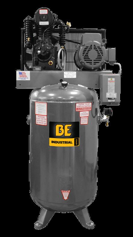

1 vertrical air compressor AC5080B AC7580B user manual BEPOWEREQUIPMENT.COM
2 table of contents table of contents Introduction 4 Using the Operator s Manual Product Identification 5 Record Identification Numbers Safety 6 Safety Precautions and Warnings Troubleshooting 7 Troubleshooting Chart Compressor Maintenance 0 Maintenance Storage Adjustments & Alignment 2 Adjusting Belt Tension 2 Pulley Alignment Installation 9 Installation Diagram Start Up Preparation 20 Start Up Preparation Maintenance 2 Stopping for Maintenance or Service 22 Daily 22 Weekly 22 Monthly 22 Every 3 Months 23 Storage of Compressor Parts Breakdown 24 CA and CAU Description of Compressor 3 What is a reciprocating compressor? 3 Description of Cooling 3 Description of Controls Pre-Operation 4 Receiving and uncrating of your compressor 4 Compressor Installation 4 Location 4 Mounting 5 Induction System 5 Noise 5 Piping Fitup 6 Safety Valves 6 Pressure Vessels 6 Electrical 7 Pressure Switch 7 Manual Relief and Shutoff Valves 7 Guards 8 Drive 2 3
3 introduction product identification Attention: Read through the complete manual prior to the initial use of your Compressor Using the Operator s manual The operating manual is an important part of your Compressor. It should be read thoroughly before initial use, and referred to often to make sure adequate safety and service concerns are being addressed. Reading the owner s manual thoroughly will help avoid any personal injury or damage to your pump. By knowing how best to operate this machine you will be better positioned to show others who may also operate the unit. You can refer back to the manual at any time to help troubleshoot any specific operating functions, so store it with the machine at all times. Record Identification Numbers COMPRESSOR If you need to contact an Authorized Dealer or Customer Service line ( ) for information on servicing, always provide the product model and identification numbers. You will need to locate the model and serial number for the pump and record the information in the places provided below. Date of Purchase: Dealer Name: Dealer Phone: Product Identification Numbers Model Number: Serial Number: WARNING: This product can expose you to chemicals including lead, which is known to the State of California to cause cancer and birth defects or other reproductive harm. For more information, go to Wash hands after handling. 4 5
4 safety troubleshooting Safety Precautions and Warnings Listed are some, but not all safety precautions that must be observed with compressors. Failure to follow any of these warnings may result in severe personal injury, death, property damage and/or compressor damage. Air from this compressor will cause severe injury or death if used for breathing or food processing. Air used for these processes must meet OSHA 29 CFR 90 or FDA regulations. This compressor is designed for use in the compression of normal atmospheric air only. No other gases, vapors or fumes should be exposed to the compressor intake, nor processed through the compressor. Disconnect all power supplies to the compressor plus any remote controllers prior to servicing the unit. Relieve all pressure internal to the compressor prior to servicing. Do not depend on check valves to hold system pressure. A properly sized safety valve must be installed in the discharge piping ahead (upstream) of any shutoff valve (block valve), heat exchanger, orifice or any potential blockage point. Failure to install a safety relief valve could result in rupturing or explosion of some compressor or safety component. Do not change the pressure setting of the safety relief valve, restrict the function of the safety relief valve, or replace the safety valve with a plug. Over pressurization of some system or compressor component can occur, resulting in severe personal injury, death and property damage. Never use plastic pipe, rubber hose, or soldered joints in any part of the compressors. Failure to ensure system compatibility with compressor piping is dangerously unsound. Never use a flammable or toxic solvent for cleaning the air filter or any parts. Do not attempt to service any part while the compressor is operating. Do not operate the compressor at pressures in excess of its rating. Do not remove any guards while the compressor is operating. Observe gauges daily to ensure compressor is operating properly. Follow all maintenance procedures and check all safety devices on schedule. Compressed air is dangerous, do not play with it. Use the correct lubricant at all times. Troubleshooting Chart NOTE: Troubleshooting problems may have similar causes and solutions. Problem Possible Cause Solutions Breaker Trips Compressor stalls Low Discharge Pressure Compressor pump knocking WARNING ALWAYS MAKE SURE ELECTRICAL POWER IS OFF BEFORE REMOVING ANY INSPECTION COVERS OR PLATES. You should always contact an authorized service center before attempting to fix or repair your air compressor. Low Voltage supply 2. Motor overloads tripped 3. Restricted air passages 4. Loose wires at contact points 5. Seized Pump. Low voltage supply to compressor 2. Loose compressor belts 3. Bad check valve 4. Seized compressor pump. Air leaks in shop 2. Leaking valves 3. Restricted air intake 4. Blown gaskets/seals 5. Worn piston rings or cylinder. Loose motor pulley or compressor flywheel. 2. Low oil level in compressor pump. 3. Carbon build up on valve and piston.. Check that incoming power wire size is adequate for compressor 2. Check that compressor is on dedicated circuit 3. Adjust belt tension 4. Check wire connections to make sure they are tight 5. Inspect transfer tubes and, check valve. Check compressor power supply for adequate breaker and wire size 2. Inspect check valve for proper operation 3. Tighten belts 4. Check compressor for proper oil level.. Tighten or replace leaking fittings, or joints 2. Clean or replace air filter. Tighten pulley or flywheel. 2. Keep oil level at recommended level for proper operation. 3. Only use factory recommended oil. 6 7
5 troubleshooting troubleshooting Troubleshooting Chart (continued) NOTE: Troubleshooting problems may have similar causes and solutions. Problem Possible Cause Solutions Excessive oil discharge in air (All Compressors have a small amount of oil carry over in compression) Compressor Overheating Excessive Belt Wear Compressor wont start in Cold weather. Worn piston rings or cylinder. 2. Restricted air intake. 3. Oil level to high. 4. Compressor has exceeded it duty cycle.. Poor ventilation 2. Dirty cooling surfaces 3. Compressor is out of its operating duty cycle. Pulley out of alignment 2. Improper belt tension 3. Pulley damaged of loose. Bad check valve 2. Compressor has wrong grade oil 3. Control lines frozen. Clean or replace air filters. 2. Reduce oil level to recommended amount. 3. Reduce compressor duty cycle (repair leaks or add another unit to handle the excess demand). Relocate compressor to any area with better ventilation (at least 8 inches from the nearest wall) 2. Clean all cooling surfaces 3. Reduce compressor duty cycle (repair leaks or add another unit to handle the excess demand). Realign pulley with flywheel 2. Re adjust belt tension. Use IS 00 (30W) compressor oil for cold weather conditions 2. Move compressor to a warmer location 3. Put a heat lamp on compressor to maintain above freezing temperatures Troubleshooting Chart (continued) NOTE: Troubleshooting problems may have similar causes and solutions. Problem Possible Cause Solutions Compressor Motor Hums wont start Unit has power but wont run Compressor Chatters (run and stops in a short period of time). Fuse or Breaker blown in main panel (or fuse in fused disconnect if applicable) 2. Low voltage to compressor 3. Compressor starting with head pressure 4. Power leads in motor or magnetic starter loose 5. Starter or Pressure switch contacts corroded or broken. Starter tripped 2. Starter coil out 3. Pressure switch closed 4. Low Oil monitor tripped (Elite units) 5. Motor or Pump locked up. Pressure switch connection corroded 2. Starter is not getting enough voltage to close coil 3. Low oil switch tripping NOTICE. Re-set breaker or replace blown fuse 2. Inspect check valve for proper operation 3. Check all power wire lead to solid connection 4. Replace starter and Pressure switch. Re-set starter 2. Replace starter and Pressure switch 3. Check unit for proper oil level 4. Replace motor or pump. Replace pressure switch 2. Check unit voltage 3. Check the oil level in the unit Low Voltage-Low voltage can cause a multitude of problems. The most common cause of low voltage is when the wire size supplying the power to the compressor is too small. The longer the run of wire the larger the diameter must be to overcome the inherent voltage loss caused by the wire resistance. The supply voltage at the main panel could also be low as supplied by you local power company or you may have too many other pieces of equipment running off the same panel. You local electrician should be contacted to evaluate and correct the problem according to the Nation Electric Code. Other Symptoms of low voltage can be flickering lights and computer screen when the compressor tries to turn on. 8 9
6 compressor maintenance storage Daily: Drain the Receiver- condensation will accumulate in the tank daily, and should be drained at least once a day. This is done to reduce corrosions of the tank from the inside. Always wear protective eye wear when draining the tank. Check Pump Oil Level - All units have a sight glass the oil level non running units should be no lower than ½ way on the sight glass if it is lower then you need to add oil until it is at least ½ way up the sight glass. Check unit for any unusual noise or vibrations. Weekly: WARNING To avoid personal injury, always shut OFF the main power supply and disconnects to the compressor, relive all air pressure from the system, and check electrical system with electrical probe before starting any service or maintenance on the compressor. Clean air filter to ensure that no dirt or heavy particulate makes its way into the compressors valve assemblies. Clean external parts of compressor and electric motor, this helps to ensure proper cooling and prevents rust and corrosion on critical parts. Check safety valves to ensure they are not stuck in place and are operating properly. Elite units Check auto tank drain for proper function. Inspect pressure switch for proper function. Inspect check valve for proper function and remove any carbon accumulation to prevent premature failure. *Clean belt guard coolers (if equipped). Storage of Compressor: Before storing the compressor for a prolonged period of time, use a blow gun to clean all debris from compressor. Shut OFF main power and turn OFF disconnect. Drain tank pressure, clean air filter, drain old oil and replace with new oil. Cover the unit to prevent dust and moisture from collecting on the unit. Monthly: Inspect complete air system for leaks to make sure the compressor does not get out of its duty cycle due to air leak in the system. Inspect oil for contamination to ensure that harmful deposits do not build up in the oil. Check belt tension, to ensure the belts do not fail pre-maturely. Tighten them as needed to ensure they do not slip. If belts are loose, tighten per instructions on next page. Failure to tighten can cause pre-mature belt failure. Every 3 months: Change oil to ensure that the compressor has proper oil level and that the oil in the machine does not deteriorate past factory specifications. Inspect valve assemblies to prevent premature failure and clean out and carbon that can form in older valves. *Elite units clean auto tank drain strainer and check for proper function. 0
7 adjustments & alignment description of compressor Adjusting Belt Tension Proper belt tension and pulley alignment must be maintained for maximum drive efficiency and for maximum belt life. The correct tensions exists if a deflection of ½ inch occurs by placing 0lbs of force midway between the motor pulley and the compressor flywheel. This deflection can be adjusted by the following procedure. The pulley should be carefully aligned with the flywheel and set screws should be kept tight.. Remove the belt guard. 2. Loosen the motor mounting bolts. 3. Shift the motor to the point where the correct deflection exists. 4. Retighten the motor mounting belts. 5. Check to ensure that the tension remain correct after tightening. 6. Re-install the belt guard. All moving parts must be guarded. NOTE: Drive belt tension and pulley alignment are done at the same time. They are discussed separately for clarity. Pulley Alignment The figure to the side shows 3 examples of misaligned pulleys. To check pulley alignment, remove the belt guard and place a straightedge against the compressor flywheel, measure and record the distance from the straightedge to the edge of the drive belt. Then measure the distance to the edge of the drive belt on the motor pulley at the same edge. As long as both points measure the same distance the pulleys will be aligned if not you will need to move the pulley until its in alignment this may take a few tries. To re-align the pulley follow the steps below.. Loosen the motor mounting bolts. 2. Remove the belt guard. 3. Loosen the set screw on the motor pulley. 4. Align the motor pulley with the compressor flywheel. 5. Re-tighten the motor pulley set screws. ANGULAR PARALLEL PULLEY GROOVE MISALIGNMENT MISALIGNMENT AXIAL MISALIGNMENT 6. Adjust the proper belt tension. PUMP DRIVE MOTOR DRIVE 7. Re-tighten the motor mounting bolts. FLYWHEEL BELT PULLY BELT EDGE EDGE 8. Re-install the belt guard. What is a reciprocating compressor? A reciprocating compressor is a piston type pump which develops pressure from the action of a piston moving through a cylinder. The cylinder, or cylinders, may be vertical, horizontal or angular. When air is drawn in from the atmosphere and compressed to its final pressure in a single stroke, the compressor is referred to as a single stage pump. Single stage units normally are used in the 90 to 25 PSI range and are available as single or multi-cylinder (twin cylinder) compressors. When the air drawn from the atmosphere is compressed first to an intermediate pressure, and then further compressed to a higher pressure, it is done in a two stage pump. These cylinders are unequal in size and the first stage always takes place in the larger, low pressure cylinder. From there it passes through the inner cooler to the smaller, high pressure cylinder. The cycle is completed as the air then moves through the after cooler and discharge line into the tank. Two stage compressors are generally used for pressure ranges from 00 to 75 PSI and deliver more air per horsepower at these pressures. This increase in efficiency is partially due to the heat dissipated as the air passes through the inner cooler. DESCRIPTION OF COOLING Our compressors are cooled by fan blades, incorporated into the driven sheave (pulley), blowing air across the intercooler, after cooler, and cylinder head. DESCRIPTION OF CONTROLS Stop/Start Receiver or plant air system pressure is controlled within limits by a pressure switch automatically stopping and starting the compressor as the air pressure reaches a maximum preset pressure (cut out) and then drops to a minimum presser pressure (cut in). STRAIGHT EDGE A B C 2 3
8 pre-operation pre-operation RECEIVING AND UNCRATING OF YOUR COMPRESSOR Before uncrating the compressor the following steps should be taken.. Immediately upon receipt of the equipment, it should be inspected for damage that may have occurred during shipment. If any damage is found, demand an inspection immediately by an inspector from the carrier. Ask him how to file a claim for damages. (See Appendix A for Details). 2. Insure that adequate lifting equipment is available for moving the machinery. 3. Read the compressor nameplate to be sure the compressor is the model and size ordered. 4. Read the motor nameplate to be sure the motor is compatible with your electrical conditions. (Volts-Phase-Hertz). Compressor Installation NOTICE Standard motors are open drip proof with a maximum ambient temperature rating of 04 degrees F. They are not suitable for salt laden, corrosive, dirty, wet, or explosive environments. WARNING Improper lifting can result in component or system damage or personal injury. Follow good shop practices and safety procedures. LOCATION Locate the compressor in an indoor area that is clean, dry, well lighted, and well ventilated, with sufficient space for safe and proper inspection and maintenance. Ambient temperatures should not exceed 04 degrees F or fall below 30 degrees unless an electric motor rated for a higher temperature is used. Inspection and maintenance checks are required daily, therefore, ample space is required around the compressor. The compressor must not be installed closer than fifteen inches from a wall or from another compressor to allow ample circulation or air across the compressor cylinders and head, and through the coolers if they are part of the system. Additional safety can be achieved by locating the pulley guard next to the wall. MOUNTING We recommend the use of rubber pads or isolators between the tank legs and the floor. If a shim is required to level the unit, place it between the pad and floor. If you bolt the unit to the floor, use the bolts as guide pins and do not tighten the bolts. The rubber pads are used to absorb machine vibration and cannot work effectively if bolted tightly. INDUCTION SYSTEM Do not locate the compressor where it could ingest or ignite toxic, explosive or corrosive vapors, ambient air temperatures exceeding 04 degrees F, water or extremely dirty air. Ingestion of any of the above noted atmospheres by the compressor could jeopardize the performance of the equipment and all personnel exposed to the total compressor. Depending on the size of the compressor and the size and construction of the compressor room it may be necessary to locate the air pickup point outside the room. Destructive pulsations can be induced by reciprocating compressors that will damage walls and break windows. Pulsation can be minimized by adding a pulsation dampener on the inlet side of the compressor. Under no circumstances should a compressor be placed in an area that may be exposed to a toxic, volatile or corrosive atmosphere nor should toxic, volatile or corrosive agents be stored near the compressor. NOISE Noise is a potential health hazard that must be considered. There are local and federal laws specifying maximum acceptable noise levels that must not be exceeded. Most of the noise from a reciprocating compressor originates from the air inlet point. Excessive noise can be greatly reduced by installing an intake noise silencer PIPING FITUP Care must be taken to avoid assembling the piping in a strain with the compressor. It should line up without having to spring or twist into position. Adequate expansion loops or bends should be installed to prevent undue stresses at the compressor resulting from the changes between hot and cold conditions. Pipe support should be mounted independently of the compressor and anchored as necessary to limit vibration and prevent expansion strains. 4 5
9 pre-operation pre-operation DANGER Safety valves are to protect system integrity in accordance with ASME Codes and ANSI B9.3 safety standards. Failure to use safety valves of the proper capacity and pressure will cause severe personal injury or death. NOTICE Standard motors are open drip proof with a maximum ambient temperature rating of 04 degrees F. They are not suitable for salt laden, corrosive, dirty, wet, or explosive environments. SAFETY VALVES Safety valves are pressure relief valves and should be sized and purchased with a pressure setting to protect the weakest link in the system. Never change the pressure setting, only the safety valve manufacturer is qualified to make a change. Safety valves are to be place ahead of any potential blockage point which included but is not limited to, shutoff valves, heat exchangers, pulsation dampeners, and discharge silencers. DANGER Failure to properly size, set & install pressure relief valves can be fatal. ASME coded pressure vessels must not be modified, welded, repaired, reworded or subjected to operation conditions outside the nameplate ratings. Such actions will negate code status, affect insurance status and may cause severe personal injury, death, and property damage. PRESSURE VESSELS Air receiver tanks and other pressure containing vessels such as, but not limited to, pulsation bottles, heat exchangers, moisture separators and traps, shall be in accordance with ASME Boiler and Pressure Vessel Code Section VIII and ANSI B9.3 Safety Standards. The installation, wiring, and all electrical controls must be in accordance with ANSI C National Electric Code, ANSE C2 National Electric Safety Code, state and local codes. All electrical work should be performed by a qualified electrician. Failure to abide by the national, state and local codes may result in physical and/or property damage. ELECTRICAL Before installation, the electrical supply should be checked for adequate wire size and transformer capacity. During installation a suitable fused or circuit breaker disconnect switch should be provided. Where a 3 phase motor is used to drive a compressor, any unreasonable voltage unbalance between the legs must be eliminated and any low voltage corrected to prevent excessive current draw. Compressors must be equipped with a properly wired magnetic motor starter or a pressure switch rated to carry the full motor current load. The coil which engages and disengages the contact points in the motor starter is controlled by the pressure switch. Never attempt to bypass the pressure switch or adjust it past the factory set pressure range. Improper installation of the electrical system can cause the motor to overheat or a short circuit to occur. Electric power always exists inside the pressure switch when there is electric power at the compressor package. Either a qualified electrician should make the pressure adjustments or the electric power supply should be disconnected and locked out before making any adjustment. NEVER exceed the designed pressure for the system or overload the motor beyond its service factor. FAILURE TO HEED THESE WARN- INGS MAY RESULT IN SERIOUS INJURY OR DEATH, PROPERTY DAMAGE AND/OR MECHANICAL FAILURE PRESSURE SWITCH The pressure switch is automatic in operation and is adjusted to start and stop the unit at the minimum and maximum desired air receiver pressure by cutting in and out the power to the electric motor. On some models, the pressure switch incorporates a release valve, which releases air between the check valve located in the receiver and discharge valve in the head of the compressor. Relieve compressor and system air pressure by opening the appropriate manual relief valve prior to servicing. Failure to relieve all system pressure may result in severe personal injury, death & property damage. GUARDS All mechanical action or motion is hazardous in varying degrees and needs to be guarded. Guarding shall be in compliance with OSHA Safety and Health Standards 29 CFR in OSHA manual 2206 and any state or local code. 6 7
10 pre-operation installation Guards must be fastened in place before starting the compressor and never removed before cutting off & locking out the main power supply. MANUAL RELIEF AND SHUTOFF VALVES Install a manual relief valve to vent the compressor to atmosphere. In those instances where the air receiver tank services a single compressor, the manual relief valve can be installed on the receiver. When a manual shut- off valve, and a safety relief valve installed upstream from the manual relief valve. These valves are to be designed and installed as to permit maintenance to be performed in a safe manner. Never substitute a check valve for a manual shut-off valve (block valve) if the purpose is to isolate the compressor from a system for servicing. Excessive speed of the compressor or driver can be lethal. Never operate the compressor beyond the manufacturer s recommendation. Bursting of the flywheel may be the greatest threat because the normal guard may not contain all the pieces. Crankshaft and connecting rod breakage is a possibility and compressor efficiency, valve life and bearing life will be abnormally reduced. DRIVES IIt is important that the compressor and motor pulleys are aligned properly and the V belt is correctly tensioned. Improper pulley alignment and belt tension are causes for motor overloading, excessive vibration, and premature belt and/or bearing failure. Removal or painting over safety labels will result in uninformed conditions. This may result in personal injury or property damage. Warnings signs and labels shall be provided with enough light to read, conspicuously located and maintained for legibility. Do not remove any warning, caution, or instructional material attached! Provisions should be made to have the instruction manual readily available to the operator and maintenance personnel. If for any reason any part of the manual becomes illegible or if the manual is lost, have it replaced immediately. The instruction manual should be periodically read to refresh one s memory, it may prevent a serious or fatal accident. INSTALLATION DIAGRAM WARNING ALWAYS turn main power disconnect off, shut off power at power panel, and drain all air pressure from tank before servicing unit. AIR-FLOW BYPASS AIR DRYER and/or AF TERCOOLER PUMP RECEIVER AIR-FLOW LINE FILTER BYPASS FEEDER LINE PRESSURE SWITCH MOTOR /4 TURN SHUT-OFF VALVE DRIP-TEE with drain FLEXIBLE AIR-LINE /4 TURN SHUT-OFF VALVE For paint spraying or similar applications, a non-lubricated supply line must be used. Shim tank so the pump is level within /8 per lineal foot MAXIMUM to distribute oil properly. Fasten to floor and NEVER force tank feet to floor without shims when tightening. To remove moisture from air line, the main feeder line must run downhill to drain-leg at a rate of /4 tp every 0 feet. NOTICE AIR/WATER FILTER with PETCOCK REGULATOR with gauge MAGNETIC STARTER RESET SWITCH MAIN DISCONNECT (ON/OFF) DRAIN LEG QUICK COUPLER MAGNETIC STARTER: Those not factory mounted on the compressor can be mounted on the wall. Mount as close to compressor as possible. Sire the wires, protect them with conduit, and provide branch circuit protection per the National Electrical Code. MOISTURE TRAP WITH DRAIN NON-LUBRICATED SUPPLY LINE Recommended pipe and fittings: Black iron pipe no smaller than tank outlet size (NPT). For system over 00 feet in length, increase by one pipe size. AIR HOSE TO AIR TOOL LUBRICATOR : NEVER use for paint spraying or similar applications. POWER PANEL 8 9
11 start up preparation maintenance The following check list shall be adhered to before putting the compressor into operation. FAILURE TO PERFORM THE CHECKS MAY RESULT IN SERIOUS INJURY OR DEATH, PROPERTY DAMAGE AND/OR MECHANICAL FAILURE. DISCONNECT AND LOCK OUT POWER SUPPLY.. Remove all loose pieces and tools around the compressor installation. 2. Check oil level in crankcase, add as necessary. 3. Check all pressure connections for tightness and leaks. 4. Check to make sure all safety relief valves are in place and operational. 5. Check to be sure all guards are in place and securely mounted. 6. Check fuses, circuit breakers and thermal overloads for proper size. 7. Open all manual shut-off valves (block valves) at and beyond the compressor discharge. 8. On all 3 phase units, after all of the above conditions have been satisfied, jog the starter switch button to check the rotational direction of the compressor. It should agree with the rotation arrow on the flywheel/pulley (counter clockwise, facing the shaft). The following procedures should be followed for start-up of a new installation, or after changes have been made to an existing installation, and/or after service repair work has been performed.. Instructions in addition to those contained within this manual, supplied by manufacturers of supporting equipment, must also be read and understood before start-up. 2. Check oil level in crankcase. 3. Drain moisture from air receiver and traps. 4. Start compressor and watch for excessive vibration or strange noises. If either is observed, stop the compressor immediately and correct. 5. Check air receiver or system pressure. 6. Manually activated safety relief valves by pulling ring or lever. 7. Check operation of controls. 8. After two days of operation check belt tension, air piping for leaks, and crankcase oil level. STOPPING FOR MAINTENANCE OR SERVICE Never assume the compressor is ready for maintenance or service because it is stopped. The automatic stop start control may start the compressor at any time! The following procedure should be followed to maximize safety when preparing for maintenance or service. 9.. Disconnect and lock-out the main power switch and hang a sign at the switch Informing of the unit being serviced Close shut-off valve (block valve) between receiver and compressor, or receiver and Plant air system, to. prevent any back-up of air flow into the area to be serviced Lock open manual vent valve and wait for the pressure in the area to be serviced (compressor, receiver, 3. etc.) to be completely relieved before starting service. The Manual vent valve may be the drain valve in 4. the receiver. NEVER remove a plug to relieve the pressure Open all manual drain valves within the area to be serviced Wait for the unit to cool before starting service, (temperatures at 25 degrees F can burn the skin), some 7. surface temperatures exceed 400 degrees F when the compressor is working) Clean up all oils spills immediately to prevent slipping. 20 2
12 maintenance maintenance Daily: Drain the Receiver- condensation will accumulate in the tank daily, and should be drained at least once a day. This is done to reduce corrosions of the tank from the inside. Always wear protective eye wear when draining the tank. Check Pump Oil Level- All units have a sight glass the oil level non running units should be no lower than ½ way on the sight glass if it is lower then you need to add oil until it is at least ½ way up the sight glass. Check unit for any unusual noise or vibrations. Weekly: Clean air filter: this will ensure that no dirt or heavy particulate makes its way into the compressors valve assemblies. Clean external parts of compressor and electric motor: this helps to ensure proper cooling and prevents rust and corrosion on critical parts. Check safety Valves: this is don t to ensure they are not stuck in place and operating properly. Elite Units Check auto tank drain for proper function Monthly: Inspect complete air system for leaks: this is done to make sure the compressor does not get out of its duty cycle due to air leak in the system. Inspect Oil for Contamination: this is done to ensure that harmful deposits do not build up in the oil. Check belt tension: this is done to ensure the belt do not fail pre-maturely, tighten them as needed to ensure they do not slip. If belts are loose, tighten per instructions on next page. Failure to tighten can cause pre-mature belt failure. Every 3 months: Change Oil: this is done to ensure that the compressor has proper oil level and that the oil in the machine does not deteriorate past factory specifications. Inspect Valve assemblies: this is done to prevent premature failure and clean out and carbon that can form in older valves. *Elite Units. Clean auto tank drain strainer and check for proper function. Inspect pressure switch for proper function. Inspect check valve for proper function and remove any carbon accumulation to prevent premature failure. *Clean belt guard coolers (if equipped). Storage of Compressor: Before storing the compressor for a prolonged period of time, use a blow gun to clean all debris from compressor. Shut OFF main power and turn OFF disconnect. Drain tank pressure, clean air filter, drain old oil and replace with new oil. Cover the unit to prevent dust and moisture from collecting on the unit
13 parts breakdown CA and CAU Parts Breakdown hp Electric 8-5 hp Gas/Diesel Two stage Cast iron Model CA 24 parts breakdown Item CAS # Part Description Crankcase Crankshaft Bearing set front Front bearing carrier Gasket front cap Capscrew hex M8x20 Seal - shaft Bearing set rear Gasket rear cap Centrifugal adapter plate Flywheel 6 7/8 Capscrew skt HD M6x20 Gasket copper Rod connecting aluminum w/bushing Valve assembly - LP inlet Plug oil fill 3/4 NPT Cover crankcase side Snapring internal Wristpin - LP piston Piston LP 05mm Piston ring set LP Gasket cylinder to crankcase Capscrew hex 0 x 25 Capscrew hex 2 x 70 Gasket sight glass Capscrew hex 6 x 80 Gasket cylinder head Head cylinder Spring unloader Plug oil drain 3/8 NPT Nut adjustment lock Cylinder Filter inlet assembly Filter element Gasket side cover Flanged sight glass Breather Nut hex - M6 Key flywheel Aftercooler Valve safety 75 PSI Intercooler Elbow aftercooler Elbow valve and unloader Qty
14 parts breakdown Gasket unloader cover Piston - HP Insert rod - bearing half Valve assembly - HP inlet A/R Shim.05 Brg Adjustment and/or Shim.00 Brg Adjustment and/or Shim.005 Brg Adjustment and/or Plunge unloader Set HP piston rings Wristpin HP piston Lockwasher Gasket copper Spacer inlet valve Valve safety 200 PSI ASME Valve assy HP/LP discharge Capscrew SKT head 8 x Cover valve Capscrew SKT head M0 x Retainer inlet valve Retainer discharge valve Lockwasher Bushing reducing 3/4 x /4 FNPT Capscrew hex M8 x Gasket aftercooler Gasket intercooler Spacer discharge valve Gasket valve cover Lockwasher Elbow street 90 degrees / Copper valve seat gasket Cap rear Weight unloader Pin - hinge Holder unloader Gasket Set 26 27
15 THE POWER YOU NEED.
120 GALLON HORIZONTAL AIR COMPRESSOR
 120 GALLON HORIZONTAL AIR COMPRESSOR User Manual BEPOWEREQUIPMENT.COM 2 table of contents Introduction 5 Using the Operator s Manual Product Identification 6 Record Identification Numbers Safety 7 Safety
Compressor Manual HP Diesel Engine Drive Reciprocating Compressor
 Compressor Manual 16.8 HP Diesel Engine Drive Reciprocating Compressor INTRODUCTION Congratulations on the purchase of your new air compressor. The air compressor is precision built from the finest materials
7.5 HP Electric Duplex Reciprocating Compressor
 7.5 HP Electric Duplex Reciprocating Compressor Owners Manual Introduction. Congratulations on the purchase of your new air compressor. The air compressor is precision built from the finest materials using
7.5, 10, 15 HP Electric Reciprocating Compressors
 7.5, 10, 15 HP Electric Reciprocating Compressors Owners Manual Introduction. Congratulations on the purchase of your new air compressor. The air compressor is precision built from the finest materials
Commercial Duty Compressors
 Commercial Duty Compressors Owners Manual Introduction. Congratulations on the purchase of your new air compressor. The air compressor is precision built from the finest materials using the finest state
Oil Free Reciprocating Compressors
 Oil Free Reciprocating Compressors Owners Manual Introduction. Congratulations on the purchase of your new air compressor. The air compressor is precision built from the finest materials using the finest
Hydraulic Driven Reciprocating & Rotary Screw Compressors
 Hydraulic Driven Reciprocating & Rotary Screw Compressors Owners Manual Introduction Congratulations on the purchase of your new air compressor. The air compressor is precision built from the finest materials
Hydraulic Driven Reciprocating & Rotary Screw Compressors
 Hydraulic Driven Reciprocating & Rotary Screw Compressors Owners Manual Introduction Congratulations on the purchase of your new air compressor. The air compressor is precision built from the finest materials
HP Gas/Diesel Engine Reciprocating Compressors
 8.5-15 HP Gas/Diesel Engine Reciprocating Compressors Owners Manual Introduction. Congratulations on the purchase of your new air compressor. The air compressor is precision built from the finest materials
AIR COMPRESSOR AC5161B AC5161BP. User Manual
 AIR COMPRESSOR AC5161B AC5161BP User Manual table of contents table of contents Safety 6 Safety Rules 7 Safety Warnings Overview 11 Basic Air Compressor Components Assembly 13 Assembling the Compressor
Gas/Diesel Engine Compressor/Generator Compressor/Generator/Welder
 Gas/Diesel Engine Compressor/Generator Compressor/Generator/Welder Owners Manual Introduction. Congratulations on the purchase of your new air compressor. The air compressor is precision built from the
Rotary Screw Compressors Gas & Diesel Driven
 Rotary Screw Compressors Gas & Diesel Driven Owners Manual Introduction. Congratulations on the purchase of your new air compressor. The air compressor is precision built from the finest materials using
FAILURE TO COMPLY WITH INSTRUCTIONS IN THIS MANUAL COULD RESULT IN THE VOIDING OF YOUR WARRANTY, AND PERSONAL INJURY, AND/OR PROPERTY DAMAGE
 Gas & Diesel Rotary Screw Compressor/Generator Compressor/Generator/Welder Owners Manual Introduction Congratulations on the purchase of your new air compressor. The air compressor is precision built from
AIR COMPRESSOR OPERATING INSTRUCTION AND PARTS LIST
 AIR COMPRESSOR OPERATING INSTRUCTION AND PARTS LIST BELT TYPE IMPORTANT PLEASE MAKE CERTAIN THAT THE PERSON WHO IS TO USE THIS EQUIPMENT CAREFULLY READS AND UNDERSTANDS THESE INSTRUCTIONS BEFORE STARTING
SPECIFICATIONS: Tank Size: 80 gallons PUMP RPMs: 1050 CFM: 40PSI; 90 PSI Max Pressure: 150 PSI Thermal overload protection
 5HP 80 GALLON TWO STAGE COMPRESSOR Models: 51866, 51870 CALIFORNIA PROPOSITION 65 WARNING: You can create dust when you cut, sand, drill or grind materials such as wood, paint, metal, concrete, cement,
Owners Manual. Compressor Generator Combination Packages HP Generator Packages kw. Compressed Air Systems
 Compressor Generator Combination Packages 35-105 HP Generator Packages 15-90 kw Owners Manual Always check www.compressed-air-systems.com for current manual and compressor service or technical information
HP Electric Rotary Screw Compressors
 75-100 HP Electric Rotary Screw Compressors Owners Manual Introduction. Congratulations on the purchase of your new air compressor. The air compressor is precision built from the finest materials using
C T h e A d va n t a g e
 C The Advantage TABLE OF CONTENTS Introduction...1 Product Numbering System...1 Safety...2 Receiving and Inspection...2 Installation...2 Electrical...3 Parts Identification...7 Lubrication...9 Start-up...10
SPECIFICATIONS Horsepower: 1.5 HP Running Maximum PSI: 125 PSI Tank Capacity: 15 Gallons CFM: 6 40 PSI 5 90 PSI
 15 GALLON AIR COMPRESSOR Model: 7678 DO NOT RETURN TO STORE Please call 800-348-5004 for parts and service CALIFORNIA PROPOSITION 65 WARNING: You can create dust when you cut, sand, drill or grind materials
Portable Oil Free Silent Series Compressor Operating Instructions
 Portable Oil Free Silent Series Compressor Operating Instructions NOTICE Carefully read this instruction manual before attempting to operate this compressor. MODEL # SERIAL # 1-800-551-2406 www.eaglecompressor.com
1. GENERAL INFORMATION WARRANTY- PARTS - SERVICE SERIAL # ITEM # Printed in Canada Issue Date: October 2010 Revision 12
 TABLE OF CONTENTS SECTION PAGE 1 GENERAL INFORMATION 2 2 SAFETY GUIDELINES 3 3 OPERATION 4 3.1 How the Compressor Works 4 3.1.1 Components 4 3.1.2 Controls 5 3.1.3 Inlet Air System 6 3.1.4 Discharge System
PRODUCT NUMBERING SYSTEM SERIES PHASE. HD: Heavy Duty (15,000+ hour life) SD: Standard Duty (5,000+ hour life) LD: Light Duty (2,000+ hour life)
 SD: Standard Duty (5,000+ hour life) LD: Light Duty (2,000+ hour life)") TABLE OF CONTENTS Product Numbering System...1 Safety...2 Receiving and Inspection...2 Installation...2 Electrical...3 Parts Identification...7 Lubrication...9 INTRODUCTION The compressor you have purchased
TABLE OF CONTENTS Product Numbering System...1 Safety...2 Receiving and Inspection...2 Installation...2 Electrical...3 Parts Identification...7 Lubrication...9 INTRODUCTION The compressor you have purchased
DISCLAIMER: SPECIFICATIONS:
 5HP 80 GALLON TWO STAGE COMPRESSOR Models: 7654 CALIFORNIA PROPOSITION 65 WARNING: You can create dust when you cut, sand, drill or grind materials such as wood, paint, metal, concrete, cement, or other
INSTRUCTION MANUAL: Industrial Series Piston Air Compressor. Model Number: V Part Number: L001128KNA
 INSTRUCTION MANUAL: Industrial Series Piston Air Compressor Model Number: V8051-335 Part Number: L001128KNA Pump Model: LP335 K335 Motor: 5 HP / 1 PH Air Tank: 80 Gal Vertical 1830 W. 15 th St. Houston,
M-3025CB-AV Fuel Pump
 SAVE THESE INSTRUCTIONS M-3025CB-AV Fuel Pump Owner s Manual TABLE OF CONTENTS General Information... 2 Safety Instructions... 2 Installation... 3 Operation... 4 Maintenance... 4 Repair... 5 Troubleshooting...
PRODUCT NUMBERING SYSTEM SERIES PHASE. 1: Single Phase 3: Three Phase
 TABLE OF CONTENTS Product Numbering System and Specifications... Safety... Receiving and Inspection... Installation... Electrical...6 Start-up...7 INTRODUCTION The compressor you have purchased is a combination
Portable Electric/Gas Compressor Operating Instructions
 Portable Electric/Gas Compressor Operating Instructions NOTICE Carefully read this instruction manual before attempting to operate this compressor. MODEL # SERIAL # 1-800-551-2406 TABLE OF CONTENTS Safety
END SUCTION CENTRIFUGAL PUMPS
 OWNERS GUIDE TO INSTALLATION AND OPERATION FW000 009 Supersedes 07 END SUCTION CENTRIFUGAL PUMPS READ THESE INSTRUCTIONS CAREFULLY Read these installation instructions in detail before installing your
Pump Owner s Manual. PLEASE! Read All Instructions Carefully Before Installing Pump
 Pump Owner s Manual PLEASE! Read All Instructions Carefully Before Installing Pump Guarantee Associate Engineering Corporation warrants that pumps purchased from them will be free of defects in material
6L Oil-less Air Compressor 53103
 6L Oil-less Air Compressor 53103 Operating Instructions Please read and save these instructions before attempting to assemble, install, operate or maintain the product. Protect yourself and others by observing
6 Litre Oil-Less Air Compressor
 Operator s Manual 6 Litre Oil-Less Air Compressor WARNING! Before using this appliance, read the Operator s manual and follow all its safety rules and instructions. SPECIFICATION HWKAC1 1.1 kw / 1.5 HP
H.S. MACHINERY RING COMPRESSORS
 OPERATION & PARTS MANUAL Thank you for purchasing an H.S Machinery Limited Regenerative Blower. This product is manufactured under strict ISO-9001-2000 quality control guidelines to ensure your satisfaction.
Routine Compressor Maintenance
 Establishing a regular, well-organized maintenance program and strictly following it is critical to maintaining the performance of a compressed air system. One person should be given the responsibility
Operating instructions Form no safety definitions
 Operating instructions Form no. 1000437 safety definitions safety symbols are used to identify any action or lack of action that can cause personal injury. Your reading and understanding of these safety
TITAN FLOW CONTROL, INC.
 PREFACE: This manual contains information concerning the installation, operation, and maintenance of Titan Flow Control (Titan FCI) Wafer Style, Dual Plate Check Valves. To ensure efficient and safe operation
Iron Horse Air Compressor part breakdown - IHD6160V1 Item Description IHD6160V1 IHD6160V1 Call for the Customer Service Department.
 Iron Horse Air Compressor part breakdown - IHD6160V1 Item Description IHD6160V1 1 Compressor w/ Flywheel CC2065 2 Discharge Tube w/ Fittings TU-23-AL 3 Pressure Gauge PG200-2.5R 4 Air Receiver 60V20X48SPL
PARTS MANUAL FOR TWO STAGE AIR COMPRESSOR
 PARTS MANUAL FOR TWO STAGE AIR COMPRESSOR SPECIFICATION CHART Model No. Horsepower Voltage-Single Phase Minimum Branch Circuit Requirement *Fuse Type Air Tank Capacity Approximate Cut-in Pressure Approximate
DIRECT-DRIVE PRESSURE WASHERS
 DIRECT-DRIVE PRESSURE WASHERS PJG SERIES PRESSURE WASHER MANUFACTURED BY: PJG-2002B PJG-2502-6.5B PJG-3002B PJG-4002B INTRODUCTION Thank you for purchasing a Mancorp Pressure Washer. This manual covers
Voltmaster Centrifugal Trash Pumps
 Voltmaster Centrifugal Trash Pumps Model TSP2, TSP3 and TSP4 Owner s Manual February 2011 Table of Contents 1 Introduction............................ 1 1.1 Read before using..................... 1 1.2
LAWN SPRINKLER, IRRIGATION PUMP
 LAWN SPRINKLER, IRRIGATION PUMP MODEL #, SP0P, SP5P, SP20P, EL0P, EL5P, EL20P SAFETY INFORMATION Please read and understand this entire manual before attempting to assemble, operate or install the product.
SPLASH LUBRICATED AIR COMPRESSOR PUMPS
 Operating Instructions SPLASH LUBRICATED AIR COMPRESSOR PUMPS Airbase Industries designs and manufactures products for safe operation. However, operators and maintenance persons are responsibile for maintaining
Installation and Operating Manual
 Installation and Operating Manual OIL-LESS RECIPROCATING AIR COMPRESSOR CIL Series INSTALLATION & OPERATING MANUAL OIL-LESS RECIPROCATING AIR COMPRESSOR TABLE OF CONTENTS Page 1 DESCRIPTIONS A. GENERAL
UNPACKING SAFETY GUIDELINES GENERAL SAFETY INFORMATION. Operating Instructions & Maintenance Manual
 Please read and save this Repair Parts Manual. Read this manual and the General Operating Instructions carefully before attempting to assemble, install, operate or maintain the product described. Protect
READ AND SAVE THESE INSTRUCTIONS. Centrifugal Downblast Exhaust Fan Belt Driven for Roof & Wall Mounting
 READ AND SAVE THESE INSTRUCTIONS INSTALLATION, OPERATING INSTRUCTIONS & PARTS MANUAL Centrifugal Downblast Exhaust Fan Belt Driven for Roof & Wall Mounting Electrical wiring and connections should be done
HEAVY DUTY ONBOARD AIR SYSTEM PART NO
 IMPORTANT: It is essential that you and any other operator of this product read and understand the contents of this manual before installing and using this product. SAVE THIS MANUAL FOR FUTURE REFERENCE
TP300 INDUSTRIAL TRASH PUMP OPERATOR S MANUAL
 TP300 INDUSTRIAL TRASH PUMP OPERATOR S MANUAL IT IS EXTREMELY IMPORTANT TO READ AND UNDERSTAND THE ENTIRE CONTENTS OF THIS OPERATOR S MANUAL BEFORE ATTEMPTING TO OPERATE THE PRODUCT. THIS EQUIPMENT IS
Installation and Service Manual for SRC25, SRC252, SRC50, SRC502, SRC75, SRC752
 Rocking Piston Compressors Installation and Service Manual for SRC25, SRC252, SRC50, SRC502, SRC75, SRC752 Thank you for purchasing the Stratus SRC series rocking piston compressor. This instruction manual
AC3020B AC3030B PORTABLE AIR
 AC3020B AC3030B PORTABLE AIR operation manual CAUTION READ THIS MANUAL CAREFULLY before operating or servicing this air compressor, to familiarize yourself with the proper safety, operation, and standard
OPERATING MANUAL AND PARTS LIST
 OPERATING MANUAL AND PARTS LIST MODEL GR309EDV ELECTRIC COMPRESSOR www.grip-rite.com TABLE OF CONTENTS Table of Contents... 1 Safety Symbols... 2 Safety Instructions... 3 Specifications... 5 Compressor
MODEL NUMBER: MEDIUM DUTY ONBOARD AIR SYSTEM
 MODEL NUMBER: 10003 MEDIUM DUTY ONBOARD AIR SYSTEM IMPORTANT: It is essential that you and any other operator of this product read and understand the contents of this manual before installing and using
Model and Series 115 VAC INDUSTRIAL DIAPHRAGM PUMPS. PumpAgents.com - buy pumps and parts online INDUSTRIAL DIAPHRAGM PUMPS
 Model 31801 and 31800 Series 115 VAC INDUSTRIAL DIAPHRAGM PUMPS INDUSTRIAL DIAPHRAGM PUMPS FEATURES Run Dry Ability Self-Priming Thermal Overload Protected Motor Easy Installation Low Amp Draw Compact
UNPACKING SAFETY GUIDELINES GENERAL SAFETY INFORMATION. Operating Instructions & Maintenance Manual
 Please read and save this Repair Parts Manual. Read this manual and the General Operating Instructions carefully before attempting to assemble, install, operate or maintain the product described. Protect
END SUCTION CENTRIFUGAL PUMPS
 OWNERS GUIDE TO INSTALLATION AND OPERATION END SUCTION CENTRIFUGAL PUMPS FW000 0 Supersedes 009 READ THESE INSTRUCTIONS CAREFULLY Read these installation instructions in detail before installing your pump.
Model &
 PumpAgents.com - Click here for Pricing/Ordering Model 31765-0092 & 31765-0094 Dual Sensor Max VSD WATER PRESSURE SYSTEM AUTOMATIC TWO STAGE WATER SYSTEM WITH PUMPGARD STRAINERS IDEAL FOR PLEASURE AND
PARTS LIST FOR AIR COMPRESSORS 15 Hp Industrial Duplex. Copyright 2009, Mi-T-M Corporation
 PARTS LIST FOR AIR COMPRESSORS 15 Hp Industrial Duplex 1 This Parts Listing has been compiled for your benefit. You can be assured your Mi-T-M Gasoline Air Compressor was constructed and designed with
Electrical... 5 Start-up... 6 Digital Pressure Switch Programming and Instructions... 7 Maintenance... 8 PRODUCT NUMBERING SYSTEM PHASE SERIES
 TABLE OF CONTENTS Product Numbering System and Specifications... Safety... Receiving and Inspection... Installation... Electrical... 5 Start-up... 6 Digital Pressure Switch Programming and Instructions...
Air / Hydraulic Pump
 Form No. 538016 Parts List & Operating Instructions for: 2510A Original Instructions Air / Hydraulic Pump Maximum Capacity: 690 bar (10,000 psi) Description: The 2510A air/hydraulic pump is designed to
SERIES G3DB/AG3DB ELEVATOR
 TM INSTRUCTIONS AND PARTS LIST SERIES G3DB/AG3DB ELEVATOR WARNING This manual, and GENERAL INSTRUCTIONS MANUAL, CA-1, should be read thoroughly prior to pump installation, operation or maintenance. SRM00059
Installation Operation & Maintenance Manual. Oil-Free (Dry) Rotary Vane Vacuum Pump Systems
 Rotary Vane Vacuum Pump Systems") Installation Operation & Maintenance Manual Oil-Free (Dry) Rotary Vane Vacuum Pump Systems Part No. 9983-0000-S07 / November 2018 OIL-FREE (DRY) ROTARY VANE VACUUM PUMP SYSTEMS TABLE OF CONTENTS CUSTOMER
Installation Operation & Maintenance Manual Oil-Free (Dry) Rotary Vane Vacuum Pump Systems Part No. 9983-0000-S07 / November 2018 OIL-FREE (DRY) ROTARY VANE VACUUM PUMP SYSTEMS TABLE OF CONTENTS CUSTOMER
IMPORTANT! READ BEFORE PROCEEDING! PHR Axial Flow Hooded Roof Ventilators
 PHR Axial Flow Hooded Roof Ventilators OPERATION & MAINTENANCE Revised: 08/24/15 IMPORTANT! READ BEFORE PROCEEDING! The information contained herein is, to the best of our knowledge, accurate and applicable
See Warranty on page 6 for important information about commercial use of this product.
 See Warranty on page 6 for important information about commercial use of this product. Operating Instructions WL6000 Series Please read and save these instructions. Read carefully before attempting to
PO Box 645, Stockton, Missouri, FAX superiorgearbox.com
 I000-7000-D0447-A 4/7/05 1 SAFETY PRECAUTIONS CAUTION Please read this entire document prior to operating the gear drive. Gear drive failure and / or injury to operators may be caused by improper installation,
Gas Wheeled Portable Owner s Manual. PO Box 1286 Johnstown, PA Phone: Fax:
 Gas Wheeled Portable Owner s Manual PO Box 1286 Johnstown, PA 15907 Phone: 814.532.4149 Fax: 814.532.4102 Revised: 4/15/2010 Introduction Congratulations on the purchase of your new J-Air compressor!
Installation. Check, Test & Start Procedure
 Installation General CAUTION: Sheet metal parts, screws, clips and similar items inherently have sharp edges, and it is necessary that the installer and service personnel exercise caution. The installation
DP-139 PUMP DIMENSIONS
 3/2019 Table of Contents NOTES TO THE OWNER... 3 SELECTION OF PUMP AND EQUIPMENT DESIGN... 3 SAFETY PRECAUTIONS... 3 WARNING... 4 INSTALLATION SCHEME... 5 ORDINARY MAINTENANCE FOR DIAPHRAGM PUMPS... 6-7
jegs.com. Installation Instructions for Ton Aluminum Floor Jack
 Installation Instructions for 80077 3-Ton Aluminum Floor Jack Contents: Specifications Warning Information Setup and Operating Instructions Preventive Maintenance and Troubleshooting Hydraulic Maintenance
READ AND SAVE THESE INSTRUCTIONS. High Velocity Restaurant-Duty Utility Set Belt Driven for Roof Mounting
 READ AND SAVE THESE INSTRUCTIONS INSTALLATION, OPERATING INSTRUCTIONS & PARTS MANUAL High Velocity Restaurant-Duty Utility Set Belt Driven for Roof Mounting Electrical wiring and connections should be
Pump Operating and Maintenance Manual - Models
 Pump Operating and Maintenance Manual - Models 78-00111 - 78-0057 Thank you for purchasing the SDI Diaphragm Pump manufactured by Comet Pump. Comet produces quality products which are safe, efficient and
AC2T & AC2T-ES INDUSTRIAL GASOLINE AIR COMPRESSOR
 AC2T & AC2T-ES INDUSTRIAL GASOLINE AIR COMPRESSOR INDUSTRIAL GAS AIR COMPRESSOR OPERATOR S MANUAL IT IS ETREMELY IMPORTANT TO READ AND UNDERSTAND THE ENTIRE CONTENTS OF THIS OPERATOR S MANUAL BEFORE ATTEMPTING
ROYCE AIR COMPRESSOR 415VOLT/3 PHASE OPERATIONS MANUAL
 ROYCE AIR COMPRESSOR 415VOLT/3 PHASE OPERATIONS MANUAL PLEASE KEEP AND READ CAREFULLY BEFORE INSTALLING COMPRESSOR Table of Contents Unit Pictures & Descriptions 1 Warning 5 Installation 6 Starting, Run
QUALITY MISTING PUMPS
 DIRECT DRIVE TOTALLY ENCLOSED FAN COOLED 60200KH, 60201KH MISTING PUMP MANUAL INCLUDING: SPECIFICATION DATA, GENERAL SAFETY PRECAUTIONS, OPERATION, INSTALLATION, PARTS, MAINTENANCE & WARRANTY QUALITY MISTING
INSTALLATION, OPERATION, AND MAINTENANCE MANUAL RBK FRP FAN
 Bulletin 62-January-20-09 ROOF UPBLAST & SIDEWALL CENTRIFUGAL FIBERGLASS EXHAUST FAN INSTALLATION, OPERATION, AND MAINTENANCE MANUAL RBK FRP FAN The M.K. Plastics catalog on the above corrosion resistant
Installation and Service Manual for RV33, RV332, RV75, RV752, RV100, RV1002
 Rotary Vane Compressors RV Series Installation and Service Manual for RV33, RV332, RV75, RV752, RV100, RV1002 Thank you for purchasing the Stratus RV series rotary vane compressor. This instruction manual
READ AND SAVE THESE INSTRUCTIONS. Centrifugal Upblast Exhaust Fan (Standard & High Pressure Exhaust) Belt Driven for Roof & Wall Mounting
 Belt Driven for Roof & Wall Mounting") READ AND SAVE THESE INSTRUCTIONS INSTALLATION, OPERATING INSTRUCTIONS & PARTS MANUAL Centrifugal Upblast Exhaust Fan (Standard & High Pressure Exhaust) Belt Driven for Roof & Wall Mounting Electrical wiring
READ AND SAVE THESE INSTRUCTIONS INSTALLATION, OPERATING INSTRUCTIONS & PARTS MANUAL Centrifugal Upblast Exhaust Fan (Standard & High Pressure Exhaust) Belt Driven for Roof & Wall Mounting Electrical wiring
Collision Repair Set. Form No No. 1517A 4-Ton Set. No. 1519A 10-Ton Set. Parts List & Operating Instructions for: 1519A. Part No. Item No.
 SPX Corporation 655 Eisenhower Drive Owatonna, MN 55060-0995 USA Phone: (507) 455-7000 Tech. Serv.: (800) 533-6127 Fax: (800) 955-8329 Order Entry: (800) 533-6127 Fax: (800) 283-8665 International Sales:
PRODUCT OPERATING MANUAL
 PRODUCT OPERATING MANUAL PANBLAST TM CS37 SUCTION BLAST CABINET Manual Number: ZVP PC 0069 00 SECTION 1. GENERAL INFORMATION 2. ASSEMBLY & INSTALLATION INSTRUCTIONS 3. OPERATING INSTRUCTIONS 4. MAINTENANCE
DIRECT-DRIVE PRESSURE WASHERS
 DIRECT-DRIVE PRESSURE WASHERS PJG SERIES PRESSURE WASHER MANUFACTURED BY: PJG-2001 PJG-2501-6.5 PJG-2501 PJG-3000 PJG-3001 PJG-3501 PJG-4001 OPERATOR s INTRODUCTION Thank you for purchasing a Mancorp Pressure
Hydraulic Immediate Need Power Pack
 Safety, Operation, and Maintenance Manual WARNING Improper use of this tool can result in serious bodily injury This manual contains important information about product function and safety. Please read
Air Trap TATSU2. Copyright 2013 by TLV CO., LTD. All rights reserved ISO 9001/ ISO M-02 (TATSU2) 7 August 2013.
 7 August 2013.") 172-65177M-02 (TATSU2) 7 August 2013 ISO 9001/ ISO 14001 Manufacturer Kakogawa, Japan is approved by LRQA LTD. to ISO 9001/14001 Air Trap TATSU2 Copyright 2013 by TLV CO., LTD. All rights reserved 1 Contents
172-65177M-02 (TATSU2) 7 August 2013 ISO 9001/ ISO 14001 Manufacturer Kakogawa, Japan is approved by LRQA LTD. to ISO 9001/14001 Air Trap TATSU2 Copyright 2013 by TLV CO., LTD. All rights reserved 1 Contents
PARTS LIST FOR AIR COMPRESSORS AC-SH20-2 AC-SV20-2 ENGINE OIL GRADE: HONDA: SAE 10W-30. Below 40 F=SAE 10W-30 ENGINE OIL CAPACITY:
 PARTS LIST FOR AIR COMPRESSORS AC-SH20-2 AC-SV20-2 ENGINE OIL GRADE: HONDA: SAE 10W-30 VANGUARD: Above 40 F=SAE30 Below 40 F=SAE 10W-30 ENGINE OIL CAPACITY: HONDA: 37 oz. VANGUARD: 40 oz. MAXIMUM PRESSURE
Jet Fans. Instruction Manual READ AND SAVE THESE INSTRUCTIONS WARRANTY
 Jet Fans Instruction Manual READ AND SAVE THESE INSTRUCTIONS WARRANTY All Leader Fan products are guaranteed to be free from defects of workmanship or material and to function satisfactorily when properly
6602LP CAPACITY: 2 TON LOW RIDER SERVICE JACK
 CONTENTS: Page 1 Specifications 2 Warning Information 3 Setup Instructions 4 Operating Instructions, Preventative Maintenance, Inspection and Proper Storage 5 Hydraulic Jack Maintenance Guide and Regular
2 TON CAPACITY PROFESSIONAL SERIES ALUMINUM JACK OWNER'S MANUAL SPECIFICATIONS
 80006 OWNER'S MANUAL CONTENTS: Page 1 Specifications 2 Warning Information 3 Setup, Operating and Preventative Maintenance 4 Troubleshooting 5 Maintenance 6 Exploded View Drawing and Replacement Parts
INSTALLATION, OPERATION AND MAINTENANCE MANUAL WALL EXHAUST FANS BELT DRIVE XBL FANS
 INSTALLATION, OPERATION AND MAINTENANCE MANUAL WALL EXHAUST FANS BELT DRIVE XBL FANS The purpose of this manual is to aid in the proper installation and operation of the fans. These instructions are intended
BOILER FEED SYSTEM OPERATION AND MAINTENANCE MANUAL
 BOILER FEED SYSTEM OPERATION AND MAINTENANCE MANUAL IMPORTANT These instructions are intended as a guide for the Installing Contractor and as a reference for the Operator, Owner and Serviceman. RETAIN
Single Stage Rotary Vane Vacuum Pump Installation and Operation Manual RX-10 RX-21 RX-25
 V acuum Pumps Single Stage Rotary Vane Vacuum Pump Installation and Operation Manual RX-10 RX-21 RX-25 www.republicsales.com Revised 10.14 2014 Republic Sales & Manufacturing Single Stage Rotary Vane Vacuum
INSTALLATION, OPERATION AND MAINTENANCE MANUAL WALL EXHAUST FANS BELT & DIRECT DRIVE XB, HV, HVA, ADD, DDS, DDP
 INSTALLATION, OPERATION AND MAINTENANCE MANUAL WALL EXHAUST FANS BELT & DIRECT DRIVE XB, HV, HVA, ADD, DDS, DDP The purpose of this manual is to aid in the proper installation and operation of the fans.
Operating Instructions - Electric Pow'r-Riser Models
 ADivisionOf Templeton, Kenly& Co., Inc. Operating Instructions - Electric Pow'r-Riser Models Table of Contents 1.0 Recieving Instructions 2.0 Safety 3.0 Specifications 4.0 Initial Installation Before Operating
TC Series Cooling Systems
 TC Series Cooling Systems Table of Contents Table of Contents...1 List of Figures...1 Safety...2 Introduction...2 General Specifications...2 Types of Coolant...2 Routine Maintenance...2 Surge Tank Coolant
Installation & Operating Manual
 Installation & Operating Manual 25INV-M 1/17 Edition NV Series Vertical Booster Stainless Steel Multistage Centrifugal Pump Congratulations On Your Choice In Purchasing This Webtrol Pump Its Quality is
READ AND SAVE THESE INSTRUCTIONS
 READ AND SAVE THESE INSTRUCTIONS Part #469003 Model Vektor -H Installation Operation and Maintenance Manual for Vektor-H Laboratory Exhaust System Receiving Greenheck model Vektor-H fans are thoroughly
UNPACKING SAFETY GUIDELINES GENERAL SAFETY INFORMATION. Operating Instructions & Maintenance Manual
 Please read and save this Repair Parts Manual. Read this manual and the General Operating Instructions carefully before attempting to assemble, install, operate or maintain the product described. Protect
Hydraulic PTO Flow Device
 Safety, Operation, and Maintenance Manual WARNING Improper use of this tool can result in serious bodily injury This manual contains important information about product function and safety. Please read
6722 Rev. A CAPACITY: 22 TON TRUCK AXLE JACK WITH AIR RETURN
 CONTENTS: Page Specifications 2 Warning Information Setup Instructions and Operating Instructions 4 Preventative Maintenance, Inspection and Proper Storage 5 Troubleshooting, Owner/User Responsibility
Single Stage Rotary Vane Vacuum Pump Installation and Operation Manual RX-40 RX-63 RX-100
 V acuum Pumps Single Stage Rotary Vane Vacuum Pump Installation and Operation Manual RX-40 RX-63 RX-100 www.republicsales.com Revised 02.15 2015 Republic Sales & Manufacturing Single Stage Rotary Vane
PORTABLE AIR COMPRESSOR
 PORTABLE AIR COMPRESSOR AC206 USER MANUAL BEPOWEREQUIPMENT.COM Introduction 4 Using the Operator s Manual 4 Specifications Product Identification 5 Record Identification Numbers Safety 6 Receipt and Inspection
Air Assist Bottle Jack Max. Capacity: 12 Tons (4313C) & 20 Tons (4321C) Operating Range: psi
 & 20 Tons (4321C) Operating Range: psi") Form No. 545742 Parts List and Operating Instructions for: 4313C 4321C Air Assist Bottle Jack Max. Capacity: 12 Tons (4313C) & 20 Tons (4321C) Operating Range: 40 150 psi 45 44 43 42 41 40 39 22 1 37 28
Form No. 545742 Parts List and Operating Instructions for: 4313C 4321C Air Assist Bottle Jack Max. Capacity: 12 Tons (4313C) & 20 Tons (4321C) Operating Range: 40 150 psi 45 44 43 42 41 40 39 22 1 37 28
M-1115S Series Fuel Pump
 SAVE THESE INSTRUCTIONS M-1115S Series Fuel Pump Owner s Manual TABLE OF CONTENTS General Information...2 Safety Instructions...2 Installation...3 Operation...4 Maintenance...5 Repair...5 Troubleshooting...9
PO Box 645, Stockton, Missouri, FAX superiorgearbox.com W D0446-A 4/1/05 1
 W000-7000-D0446-A 4/1/05 1 SAFETY PRECAUTIONS CAUTION Please read this entire document prior to operating the gear drive. Gear drive failure and / or injury to operators may be caused by improper installation,
ol Series Climate Control Contr Instruction Manual Manual No C105 October 2004 Edition
 Climate Control Contr ol Series Instruction Manual This manual contains important safety information and should be made available to all personnel who operate and/or maintain this product. Carefully read