AIR COMPRESSOR AC5161B AC5161BP. User Manual
|
|
|
- Donna Ward
- 5 years ago
- Views:
Transcription
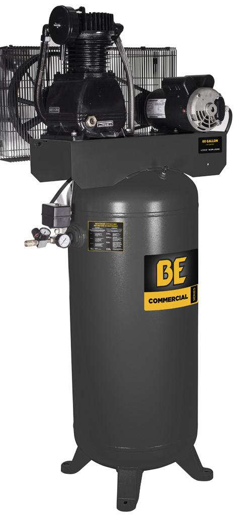
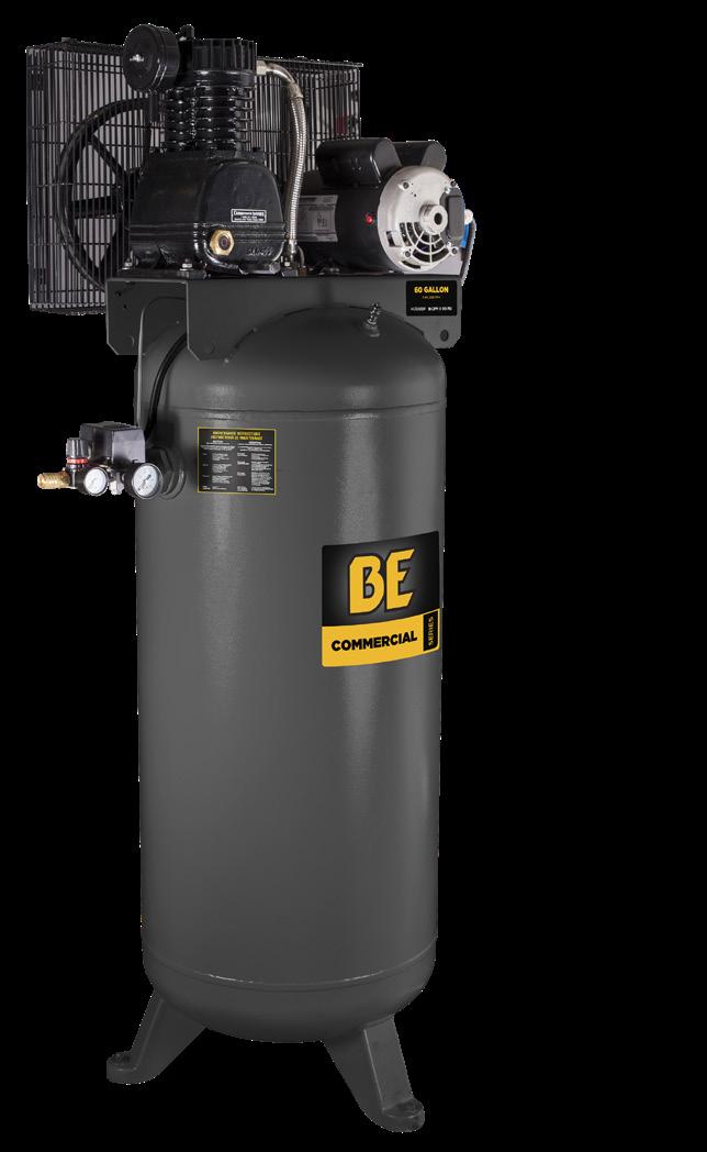

1 AIR COMPRESSOR AC5161B AC5161BP User Manual
2 table of contents table of contents Safety 6 Safety Rules 7 Safety Warnings Overview 11 Basic Air Compressor Components Assembly 13 Assembling the Compressor Installation 15 Installation Chart 16 Typical Installation Controls 17 Compressor Controls Electrical Power Requirements 18 Electrical Wiring 18 Main Power Panel 18 Main Power Disconnect Switch 18 Low Voltage Problems 19 Grounding Instructions Break-In of the Pump 20 Break-In of the Pump Operating 22 Daily Start-up 22 Cold Weather Starting 22 Shutdown Maintenance 24 Draining the Tank 24 Checking the Oil 24 Changing the Oil 25 Belt Tension and Pulley Alignment 25 Adjusting Drive Belt Tension 26 Pulley Alignment 27 Cleaning the Air Filter 28 Checking the Relief Valve 27 Testing for Leaks 27 Storage 28 Service Interval Troubleshooting 29 Troubleshooting Chart Warranty 31 Warranty 2 3
3 introduction product identification Attention: Read through the complete manual prior to the initial use of your Compressor Using the Operator s manual The operating manual is an important part of your Compressor. It should be read thoroughly before initial use, and referred to often to make sure adequate safety and service concerns are being addressed. Reading the owner s manual thoroughly will help avoid any personal injury or damage to your pump. By knowing how best to operate this machine you will be better positioned to show others who may also operate the unit. You can refer back to the manual at any time to help troubleshoot any specific operating functions, so store it with the machine at all times. Record Identification Numbers Compressor If you need to contact an Authorized Dealer or Customer Service ( ) for information on servicing, always provide the product model and identification numbers. You will need to locate the model and serial number for the pump and record the information in the places provided below. Date of Purchase: Dealer Name: Dealer Phone: Product Identification Numbers Model Number: Serial Number: 4 5
4 safety safety Save these Instructions SAFETY RULES The safety alert symbol ( ) is used with a signal word (DANGER, CAUTION, ), a pictorial and/or a safety message to alert you to hazards. DANGER indicates a hazard which, if not avoided, will result in death or serious injury. indicates a hazard which, if not avoided, could result in death or serious injury. CAUTION indicates a hazard which, if not avoided, might result in minor or moderate injury. NOTICE indicates a situation that could result in equipment damage. Follow safety messages to avoid or reduce the risk of injury or death. explosion flying objects This is the safety alert symbol. It is used to alert you to potential personal injury hazards. Obey all safety messages that follow this symbol to avoid possible injury or death. Hazard Symbols and Meanings fire toxic fumes moving parts hot surface Risk of Fire or Explosion. Never spray flammable liquids in confined area. It is normal for the motor and pressure switch to produce sparks while operating. If sparks come into contact with vapors from gasoline or other solvents, they may ignite, causing fire or explosion. Always operate the compressor in a well-ventilated area. Do not smoke while spraying. Do not spray where sparks or flame are present. Keep compressor as far from spray area as possible. Risk of Bursting. Do not weld, drill or modify the air tank of this compressor. Welding or modifications on the air compressor tank can severely impair tank strength and cause an extremely hazardous condition. Welding or modifying the tank in any manner will void the warranty. Check the manufacturer s maximum pressure rating for air tools and accessories. Compressor outlet pressure must be regulated so as to never exceed the maximum pressure rating of the tool. Relieve all pressure through the hose before attaching or removing accessories. Do not adjust the relief valve for any reason. Doing so voids all warranties. The relief valve has been pre-set at the factory for the maximum pressure of this unit. Personal injury and/or property damage may result if the valve is tampered with. Do not use plastic or pvc pipe for compressed air. Use only galvanized steel pipe and fittings for compressed air distribution lines. hearing risk electric shock read manual 6 7

5 safety safety Risk of Electrical Shock. Risk of Eye Injury. Never use an electric air compressor outdoors when it is raining or on a wet surface, as it may cause an electric shock. Risk of Injury. This unit starts automatically. ALWAYS shut off the main power disconnect, and bleed all pressure from the system before servicing the compressor, and when the compressor is not in use. Do not use the unit with the shrouds or belt guard removed. Serious injury could occur from contact with moving parts. Stay alert and watch what you are doing when operating the compressor. Do not use the compressor while tired or under the influence of drugs or alcohol. Risk of Burns. High temperatures are generated by the pump and manifold. To prevent burns or other injuries, DO NOT touch the pump, manifold or transfer tube while the pump is running. Allow them to cool before handling or servicing. Keep children away from the compressor at all times. Risk of airbourne chemicals. Be certain to read all labels when you are spraying paints or toxic materials, and follow the safety instructions. Use a respirator mask if there is a chance of inhaling anything you are spraying. Read all instructions and be sure that your respirator mask will protect you. Never directly inhale the compressed air produced by a compressor as it is not suitable for breathing purposes. Always wear ANSI Z87.1 approved safety goggles when using an air compressor. Never point any nozzle or sprayer toward a person or any part of the body. Equipment can cause serious injury if the spray penetrates the skin. Risk of Hearing Loss. Always wear hearing protection when using an air compressor. Failure to do so may result in hearing loss. Wash hands after handling. The power cord on this product contains lead, a chemical known to the State of California to cause cancer, and birth defects or other reproductive harm. NOTICE ELECTRICAL WIRING. Refer to the air compressor s serial label for the unit s voltage and amperage requirements. Ensure that all wiring is done by a licensed electrician, in accordance with the National Electrical code. CALIFORNIA PROPOSITION 65 : This product contains lead and other chemicals known to the State of California to cause cancer, birth defects and/or reproductive harm. Wash your hands after handling this product. 8 9
6 safety overview CAUTION 1. Drain the moisture from the tank on a daily basis. A clean, dry tank will help prevent corrosion. 2. Pull the pressure relief valve ring daily to ensure that the valve is functioning properly, and to clear the valve of any possible obstructions. 3. To provide proper ventilation for cooling, the compressor must be kept a minimum of 12 inches (31 cm) from the nearest wall, in a well-ventilated area. 4. To prevent damage to tank and compressor on stationary models, the tank must be shimmed to the pump base is level within 1/8 to distribute oil properly. All feet must be supported, shimming where necessary, prior to attaching to the floor. Fasten all feet to floor. We also recommend the use of vibration pads ( ) under tank feet. 5. Fasten the compressor down securely if transporting is necessary. Pressure must be released from the tank before transporting. 6. Protect the air hose from damage and puncture. Inspect them weekly for weak or worn spots, and replace if necessary. 7. To reduce the risk of electric shock, do not expose to rain. Store indoors. Overview BASIC AIR COMPRESSOR COMPONENTS The basic components of the air compressor are the electric motor, Thermal Overload Protection System (TOPS), pump, and receiver (tank). The tank may be vertical or horizontal, varying in size and capacity. The electric motor (see A) powers the pump. TOPS senses both temperature and current, providing more complete motor overload protection than a magnetic starter, which senses only current. If TOPS senses an overload condition, it will automatically shutdown the compressor. Allow minutes for the unit to cool down, then press the reset button on the motor to restart the compressor. The pump (see B) compresses the air and discharges it into the tank. The tank (see C) stores the compressed air. The pressure switch (see D) shuts down the motor and relieves air pressure in the pump and transfer tube when the air pressure in the tank reaches the kick out pressure. As compressed air is used and the pressure level in the tank drops to the kick in pressure, the pressure switch restarts the motor automatically, without warning and the pump resumes compressing air
7 overview assembly BASIC AIR COMPRESSOR COMPONENTS FIG 1 B C A D Assembly ASSEMBLING THE COMPRESSOR 1. Unpack the air compressor. Inspect the unit for damage. If the unit has been damaged in transit, contact the carrier and complete a damage claim. Do this immediately as there are time limitations to damage claims. The carton should contain: air compressor operator and parts manuals 2. Check the compressor s serial label to ensure that you have received the model ordered, and that it has the required pressure rating for its intended use. 3. Set up the compressor according to the following guidelines: Never place the compressor in an area where there are fumes from flammable fluids such as paint, solvents, or gasoline. It is normal for the motor and pressure switch to produce sparks while operating. If sparks come into contact with flammable fumes, they may ignite, causing a fire or explosion. Always operate the compressor in a well ventilated area. a. For optimum performance, locate the compressor close to the power panel, as specified in ELECTRICAL POWER REQUIREMENTS, and as close as possible to the place where the air will be used. This ensures maximum power to the compressor and maximum air pressure to the tool. If both of these conditions cannot be met, it is better to locate the compressor close to the power panel, and use a longer hose to reach the usage area. b. The compressor must be at least 12 inches (31 cm) from any wall or obstruction, in a clean, well-ventilated area, to ensure sufficient air flow and cooling. c. In cold climates, place the compressor in a heated building, to reduce problems with lubrication, motor starting, and freezing of water condensation. d. Remove the compressor from the shipping pallet and place it on the floor or a hard, level surface. The compressor must be level to ensure proper lubrication of the pump and good drainage of the moisture in the tank

8 assembly installation CAUTION The shipping pallet is not designed as a base for an operating the compressor. Operating the compressor while it is on the pallet will void your warranty. Installation INSTALLATION CHART e. To prevent damage to tank and pump, the tank must be shimmed so the pump is level within 1/8 per lineal foot maximum to distribute oil properly. Fasten to floor and NEVER force tank feet to floor without shims when tightening. We also recommend the use of vibration pads ( ) under tank feet (see A). 5. Connect an air hose (not included) to the compressor. FIG 4 FIG 2 Risk of bursting, resulting in injury. Never use Plastic pipe for compressed air. CAUTION Never use lubricator for paint spraying or similar applications. A. Air flow B. Feeder line C. Drain leg D. Moisture trap with drain E. Non-lubricated supply line F. 1/4 turn valve G. Bypass H. Air dryer or aftercooler J. Line filter K. Drip tee with drain L. Air/water filter with petcock M. Regulator N. Lubricator P. Quick coupler R. Air hose to tool T. Flexible air line 14 15
9 installation controls TYPICAL INSTALLATION Air dryers and after coolers An air dryer or aftercooler is installed directly in the air line. Moisture removal and air filtration As the air cools, moisture will condense in the lines. This moisture must be removed before it reaches the tool being used. To remove this moisture, run the main air line downhill to a moisture trap and drain. Air/ water filters should also be installed in the positions shown. Air pressure regulation The air pressure gauge on the pressure switch measures air pressure inside the tank, not pressure in the air line. Install an air regulator in the drop line for each tool, to regulate air pressure to that tool. Never exceed the maximum pressure rating of the tool. Air lubrication Install an air lubricator only for those tools requiring lubrication. Do not use a lubricator for paint spraying or similar applications. The oil will contaminate the paint and ruin the job. Shut off valves Install shut off valves in each drop line, to isolate the tool and its accessories for servicing. You can also install a bypass line around an accessory. Controls COMPRESSOR CONTROLS Motor Reset Switch TOPS senses both temperature and current, providing more complete motor overload protection than a magnetic starter, which senses only current. If TOPS senses an overload condition, it will automatically shut down the compressor. Allow minutes for the unit to cool down, than press the reset button on the motor to restart the compressor. If the motor shuts down because of overload, wait minutes so the motor can cool down, then press (NEVER force) the reset switch on the front of the motor to restart the motor. Pressure Switch (see A) For your safety, tank pressure is preset within the switch and must never be tampered with. This switch turns on the compressor. It is operated manually, but when in the ON position, it allows the compressor to start up or shut down automatically, without warning, upon air demand. ALWAYS set this switch to OFF when the compressor is not being used, and before unplugging the compressor. The pressure switch also automatically bleeds pressure from the pump head when the pump stops. This feature eliminates back pressure in the pump, ensuring easier starting. Pressure Relief Valve (see B) If the pressure switch does not shut down the motor when pressure reaches the preset level, this valve will pop open automatically to prevent over pressurization. To operate manually, pull the ring on the valve to relieve air pressure in the tank. Pull the ring daily to test. Tank Pressure Gauge (see C) This gauge measures the pressure level of the air stored in the tank. It is not adjustable by the operator, and does not indicate line pressure. Measures pressure in tank, not line pressure FIG 5
10 electrical power requirements electrical power requirements Electrical Power Requirements ELECTRICAL WIRING Refer to the air compressor s serial label for the unit s voltage and amperage requirements. Ensure that all wiring is done by a licensed electrician, in accordance with the National Electrical Code. Use electrical conduit to protect the wiring. MAIN POWER PANEL For best performance and reliable starting, the air compressor must be installed on a dedicated circuit, as close as possible to the electrical power panel. Provide circuit breaker or fuse protection at your main power panel. Use time delay fuses on the circuit, because the compressor will momentarily draw several times its specified amperage when first started. MAIN POWER DISCONNECT SWITCH Install a main power disconnect switch in the line from the panel to the compressor. The main power disconnect switch must be located near the compressor, for ease of use and safety. When turned OFF, the main power disconnect switch shuts off all power to the compressor. When it is turned ON, the compressor will start and stop automatically, controlled by the pressure switch. LOW VOLTAGE PROBLEMS Low voltage will cause difficult starting or an overload. Low voltage can be caused by a low supply voltage from the local power company, other equipment running on the same line, or inadequate wiring. If any other electrical devices are drawing from the compressor s circuit, it may fail to start. Low voltage to the compressor can be caused by a supply wire of insufficient gauge for the distance between the compressor and the power source. The longer the distance, the larger the wire gauge (lower the number) must be, to overcome the inherent voltage loss caused by the wire resistance. Refer to the National Electrical Code to determine proper wire size for your circuit. If the wiring is not adequate, the input voltage will drop by 20 to 40 volts at startup. Low voltage or an overloaded circuit can result in sluggish starting that causes the circuit breaker to trip, especially in cold conditions. GROUNDING INSTRUCTIONS This product must be connected to a grounded, metallic, permanent wiring system, or an equipment - grounding terminal or lead on the product
11 break-in of the pump break-in of the pump Break-In of the Pump FIG 9 BREAK-IN OF THE PUMP NOTICE The pump is shipped with break-in oil which should be changed after the first 8 hours of operation. 1. Make sure the power is connected at the power panel. 2. Check the oil level in the pump (see Checking the Oil in the maintenance section). 3. Open the petcock (see F). CAUTION Escaping air and moisture can propel debris that may cause eye injury. Wear safety goggles when opening petcock. 4. Turn ON the main power disconnect switch. Turn the pressure switch to the AUTO position (see D). The motor should start. Allow the compressor to run for 30 minutes, to break in the internal parts. NOTICE After about 30 minutes, If the unit does not operate properly, SHUT DOWN IMMEDIATELY, and contact Product Service. 5. After about 30 minutes, turn the pressure switch to the OFF position (see C). 6. Shut OFF the main power disconnect. 7. Close the petcock (see E). Turn in the clockwise direction. 8. Turn ON the main power disconnect switch. Turn the pressure switch to the AUTO position. The compressor will start and fill the tank to the cut-out pressure and stop. F Open Close E NOTICE As compressed air is used, the pressure switch will restart the motor automatically
. 4. Turn ON the main power disconnect switch. Turn the pressure switch to the AUTO position (see D). The pump will start filling the tank with air.")
12 operating operating Operating DAILY STARTUP 1. Check the oil level in the pump (see Checking the Oil in the maintenance section). 2. Make sure the main power disconnect switch is shut OFF. 3. Close the tank petcock (see E). 4. Turn ON the main power disconnect switch. Turn the pressure switch to the AUTO position (see D). The pump will start filling the tank with air. When the air pressure in the tank reaches the level preset at the factory, the pressure switch will turn off the electric motor. As air is used and the pressure level in the tank drops, the pressure switch will start the motor and the pump will begin refilling the tank. High temperatures are generated by the electric motor and the pump. To prevent burns or other injuries, DO NOT touch the compressor while it is running. Allow it to cool before handling or servicing. Keep children away from the compressor at all times. NOTICE If the unit does not operate properly, SHUT DOWN IMMEDIATELY, and contact your nearest Service Center or call the factory s Customer Service Department. DO NOT return the unit to the store where it was purchased. FIG 10 CAUTION Escaping air and moisture can propel debris that may cause eye injury. Wear safety goggles when opening petcock. COLD WEATHER STARTING In cold weather check that the air filter(s) are clean. ALWAYS use synthetic, non-detergent air compressor oil. Open the petcock (F) to depressurize the tank to zero PSI before starting. If the compressor will not start, relocate it in a warmer location. SHUTDOWN 1. Turn the pressure switch to the OFF position (see C). 2. Shut OFF the main power disconnect switch. 3. Reduce pressure in the tank through the outlet hose. You can also pull the tank safety valve ring (see G) and keep it open to relieve pressure in the tank 4. Open the petcock (see F) to allow moisture to drain from the tank. F Open Close E 22 23

13 maintenance maintenance Maintenance DRAINING THE TANK This unit starts automatically. ALWAYS shut off the main power disconnect, and bleed all pressure from the system before servicing the compressor, and when the compressor is not in use. Do not use the unit with the shrouds or belt guard removed. Serious injury could occur from contact with moving parts. Regular maintenance will ensure trouble free operation. Your electric powered air compressor represents high quality engineering and construction; however, even high quality machinery requires periodic maintenance. The items listed below should be inspected on a regular basis. CHECKING THE OIL Condensation will accumulate in the tank. To prevent corrosion of the tank from the inside, this moisture must be drained at the end of every workday. Be sure to wear protective eyewear. Relieve the air pressure in the system and open the petcock on the bottom of the tank to drain. Check the level of oil in the pump with the sight glass. The pump oil level must be between A and B (See Fig. 7). Do not overfill or under fill. NOTE: Use synthetic, non-detergent air compressor oil. CHANGING THE OIL Remove the oil plug (C) (Fig. 7) and drain the oil until it slows to a drip, then close. Add oil (approx. 33 oz grams) to the pump by first removing the breather plug (E). Add oil until the level viewed through the sight glass (D) is between FULL (A) and ADD (B). Never overfill or under fill the pump. NOTE: The compressor is pre-filled with synthetic oil. Use synthetic, nondetergent air compressor oil. A = Full B = Add C = Oil drain plug D = Oil level sight glass E = Oil fill plug FIG 13 BELT TENSION AND PULLEY ALIGNMENT This unit starts automatically. ALWAYS shut off the main power disconnect, and bleed all pressure from the system before servicing the compressor, and when the compressor is not in use. Do not use the unit with the shrouds or belt guard removed. Serious injury could occur from contact with moving parts. NOTE: Drive belt tensioning and pulley alignment are done at the same time. They are discussed separately for clarity. ADJUSTING DRIVE BELT TENSION Proper belt tension and pulley alignment must be maintained for maximum drive efficiency and belt life. The correct tension exists if a deflection (see A) of 1/2 (13 mm) occurs by placing 10 lb (4.6 kg) of force (see B) midway between the motor pulley and the pump flywheel. This deflection can be adjusted by the following procedure. The pulley should be carefully aligned with the flywheel, and all setscrews should be kept tight. 1. Remove the belt guard. 2. Loosen the motor mounting bolts. 3. Shift the motor to the point where the correct deflection exists. 4. Retighten the motor mounting bolts. 5. Check to ensure that the tension remained correct. 6. Reinstall the belt guard. All moving parts must be guarded. E D C 24 25

14 maintenance maintenance FIG 14 PULLEY ALIGNMENT To check pulley alignment, remove the belt guard and place a straightedge (see A) against the pump flywheel (see B). Measure and record the distance from the straightedge to the edge of the drive belt at point C. Then measure the distance from the straightedge to the edge of the drive belt again at points D and E. Both distances should be the same as at point C. If D or E are different from C, there is a misalignment which must be corrected before the compressor is run. To correct a pulley misalignment, use the following procedure. 1. Remove the belt guard. 2. Loosen the motor mounting bolts. 3. Loosen the setscrew on the motor pulley. 4. Align the motor pulley with the pump flywheel (C = D = E). 5. Retighten the motor pulley setscrew. 6. Adjust the proper belt tension. 7. Retighten the motor mounting bolts. 8. Reinstall the belt guard. All moving parts must be guarded. CLEANING THE AIR FILTER A dirty air filter will reduce the compressor s performance and life. To avoid any internal contamination of the pump, the filter should be cleaned frequently, and replaced on a regular basis. Felt filters should be cleaned in warm, soapy water, rinsed, and allowed to air dry before reinstallation. Paper filters should be replaced when dirty. Do not allow the filter to become filled with dirt or paint. If the filter becomes filled with paint, it should be replaced. Direct exposure to dirty conditions or painting areas will void your warranty. FIG 16 H = Wingnut I = Metal cover J = Filter element CHECKING THE RELIEF VALVE Pull the relief valve daily to ensure that it is operating properly and to clear the valve of any possible obstructions. TESTING FOR LEAKS Check that all connections are tight. A small leak in any of the hoses, transfer tubes, or pipe connections will substantially reduce the performance of your air compressor. If you suspect a leak, spray a small amount of soapy water around the area of the suspected leak with a spray bottle. If bubbles appear, repair or replace the faulty component. Do not overtighten any connections. FIG 15 STORAGE Before storing the compressor for a prolonged period, use an air blow gun to clean all dust and debris from the compressor. Disconnect the power cord and coil it up. Pull the pressure relief valve to release all pressure from the tank. Drain all moisture from the tank. Clean the filter element and filter housing; replace the element if necessary. Drain the oil from the pump crankcase and replace it with new oil. Cover the entire unit to protect it from moisture and dust
15 maintenance troubleshooting SERVICE INTERVAL Inspect and clean air filter Check pump oil level Change pump oil Operate the pressure relief valves Check belt tension Drain tank Check and tighten all bolts (Do not overtighten) Weekly Daily Every 200 hours of use Daily Every 250 hours of use Daily After first 8 hour and every 500 hours of use Troubleshooting TROUBLESHOOTING CHART PROBLEM POSSIBLE CAUSE SOLUTION Excessive current draw trips circuit breaker Compressor stalls Low discharge pressure Compressor pump knocking Oil in discharge air Low voltage/motor overload Drive belt too tight Restricted air passages Low voltage motor Bad check valve Seized pump Air leaks Leaking valves Restricted air intake Blown gaskets Worn piston rings or cylinder Loose engine pulley or compressor flywheel Low oil level in pump crankcase Excess carbon on valves or top of piston Worn piston rings or cylinder Restricted air intake Oil level too high Check that power supply is adequate and that compressor is on a dedicated circuit. Readjust belt tension Inspect and replace transfer tubes or check valve, as required. Furnish adequate power. Replace the check valve. Contact authorized service center. Tighten or replace leaking fittings or connections. Do not overtighten. Contact authorized service center. Clean or replace air filter element(s). Contact authorized service center. Contact authorized service center. Retighten pulley and flywheel. Check alignment. Keep oil at proper level at all times. Contact authorized service center. Contact authorized service center. Clean or replace the air filter element(s). Reduce to proper level
16 troubleshooting warranty PROBLEM POSSIBLE CAUSE SOLUTION Overheating Poor ventilation Relocate compressor to an area with cool, dry, well circulated air, at least 12 in. from nearest wall. Excessive belt wear Compressor won t start in cold temperatures Dirty cooling surfaces Pulley out of alignment Improper belt tension Pulley wobbles Too much back pressure in tank 40W oil in crankcase Compressor too cold Clean all cooling surfaces thoroughly. Realign pulley with compressor flywheel. Readjust. Replace the pulley and check for a damaged crankshaft or flywheel. Open petcock when starting motor. Use synthetic, non-detergent air compressor oil. Move compressor to a warmer location. BE warrants that each new product will be free of any manufacturer defects in workmanship for the set warranty period of the product. Warranty applies to the original purchaser of the product and cannot be transferred. This warranty does not cover normal wear items, including but not limited to: seals, packings, valves, o-rings, spark plugs etc. Warranty does not include normal maintenance like oil changes, filters or valve adjustments. Nor does it include misuse of product. Warranty approval is at the sole discretion of BE. In no event shall BE Inc be liable for any indirect, incidental or consequential damages from the sale or use of the product. This disclaimer applies both during and after the term of this warranty. BE disclaims liability for any implied warranties, including implied warranties of merchantability and fitness for a specific purpose, after the applicable term of this warranty. CFM: Cubic feet per minute; a unit of measure of air flow. PSI: Pounds per square inch; a unit of measure of air pressure. Kick-in pressure: Factory set low pressure point that starts the compressor to repressurize the tank to a higher pressure. Kick-out pressure: Factory set high pressure point that stops the compressor from increasing the pressure in the tank above a certain level. Well-ventilated: A means of providing fresh air in exchange for dangerous exhaust or vapors. Dedicated circuit: An electrical circuit reserved for the exclusive use of the air compressor. ASME: American Society of Mechanical Engineers. Indicates that the components are manufactured, tested and inspected to the specifications set by ASME. CSA: Canadian Standards Association Indicates that the products that have this marking have been manufactured, tested and inspected to standards that are set by CSA. Canadian Standards Association (USA) Indicates that the products that have this marking have been manufactured, tested and inspected to standards that are set by CSA. These products also conform to U.L. standard For more information on warranty and returns, please visit the support section at: bepowerequipment.com or call
17 THE POWER YOU NEED. if you need assistance with the assembly or operation of your compressor please call or visit the support section at BEPOWEREQUIPMENT.COM
SPECIFICATIONS Horsepower: 1.5 HP Running Maximum PSI: 125 PSI Tank Capacity: 15 Gallons CFM: 6 40 PSI 5 90 PSI
 15 GALLON AIR COMPRESSOR Model: 7678 DO NOT RETURN TO STORE Please call 800-348-5004 for parts and service CALIFORNIA PROPOSITION 65 WARNING: You can create dust when you cut, sand, drill or grind materials
INSTRUCTION MANUAL. Premium Submersible. IMPORTANT: Please read this manual carefully before running this air compressor and save it for reference.
 model no. 299-3117-6 Premium Submersible AIR SUMP COMPRESSOR PUMP FPO Product style and configuration may vary. IMPORTANT: Please read this manual carefully before running this air compressor and save
SPECIFICATIONS: Tank Size: 80 gallons PUMP RPMs: 1050 CFM: 40PSI; 90 PSI Max Pressure: 150 PSI Thermal overload protection
 5HP 80 GALLON TWO STAGE COMPRESSOR Models: 51866, 51870 CALIFORNIA PROPOSITION 65 WARNING: You can create dust when you cut, sand, drill or grind materials such as wood, paint, metal, concrete, cement,
Pump Owner s Manual. PLEASE! Read All Instructions Carefully Before Installing Pump
 Pump Owner s Manual PLEASE! Read All Instructions Carefully Before Installing Pump Guarantee Associate Engineering Corporation warrants that pumps purchased from them will be free of defects in material
AIR COMPRESSOR OPERATING INSTRUCTION AND PARTS LIST
 AIR COMPRESSOR OPERATING INSTRUCTION AND PARTS LIST BELT TYPE IMPORTANT PLEASE MAKE CERTAIN THAT THE PERSON WHO IS TO USE THIS EQUIPMENT CAREFULLY READS AND UNDERSTANDS THESE INSTRUCTIONS BEFORE STARTING
AC2T & AC2T-ES INDUSTRIAL GASOLINE AIR COMPRESSOR
 AC2T & AC2T-ES INDUSTRIAL GASOLINE AIR COMPRESSOR INDUSTRIAL GAS AIR COMPRESSOR OPERATOR S MANUAL IT IS ETREMELY IMPORTANT TO READ AND UNDERSTAND THE ENTIRE CONTENTS OF THIS OPERATOR S MANUAL BEFORE ATTEMPTING
1. GENERAL INFORMATION WARRANTY- PARTS - SERVICE SERIAL # ITEM # Printed in Canada Issue Date: October 2010 Revision 12
 TABLE OF CONTENTS SECTION PAGE 1 GENERAL INFORMATION 2 2 SAFETY GUIDELINES 3 3 OPERATION 4 3.1 How the Compressor Works 4 3.1.1 Components 4 3.1.2 Controls 5 3.1.3 Inlet Air System 6 3.1.4 Discharge System
AC3020B AC3030B PORTABLE AIR
 AC3020B AC3030B PORTABLE AIR operation manual CAUTION READ THIS MANUAL CAREFULLY before operating or servicing this air compressor, to familiarize yourself with the proper safety, operation, and standard
DISCLAIMER: SPECIFICATIONS:
 5HP 80 GALLON TWO STAGE COMPRESSOR Models: 7654 CALIFORNIA PROPOSITION 65 WARNING: You can create dust when you cut, sand, drill or grind materials such as wood, paint, metal, concrete, cement, or other
C T h e A d va n t a g e
 C The Advantage TABLE OF CONTENTS Introduction...1 Product Numbering System...1 Safety...2 Receiving and Inspection...2 Installation...2 Electrical...3 Parts Identification...7 Lubrication...9 Start-up...10
Belt Driven Compressor Operation Manual Model No. SACBD-100
 Belt Driven Compressor Operation Manual Model No. SACBD-100 www.synairgy-eu.com Contents Important Notice 3 Preparation for Usage 3 Safety Guidelines 4-5 Caution 6 Brief Description 6 Compressor Overview
110 Volt/12 Volt Portable Inflator
 110 Volt/12 Volt Portable Inflator Owner s Manual WARNING: Read carefully and understand all ASSEMBLY AND OPERATION INSTRUCTIONS before operating. Failure to follow the safety rules and other basic safety
Portable Oil Free Silent Series Compressor Operating Instructions
 Portable Oil Free Silent Series Compressor Operating Instructions NOTICE Carefully read this instruction manual before attempting to operate this compressor. MODEL # SERIAL # 1-800-551-2406 www.eaglecompressor.com
T1-Titanium Non-HVLP Spray Gun
 T1-Titanium Non-HVLP Spray Gun THE SPRAY GUN PEOPLE FOR PRODUCT INFORMATION CALL: 1-800-742-7731 Important Safety Instructions Read all warnings and instructions in this manual. Save these instructions.
8500M INDUSTRIAL GASOLINE GENERATOR OPERATOR S MANUAL
 8500M INDUSTRIAL GASOLINE GENERATOR OPERATOR S MANUAL IT IS EXTREMELY IMPORTANT TO READ AND UNDERSTAND THE ENTIRE CONTENTS OF THIS OPERATOR S MANUAL BEFORE ATTEMPTING TO OPERATE THE PRODUCT. THIS EQUIPMENT
Airless Spray Gun INSTRUCTIONS DP psi (345 bar) Maximum Working Pressure
 Maximum Working Pressure") INSTRUCTIONS DP-6376 Airless Spray Gun 5000 psi (345 bar) Maximum Working Pressure INSTRUCTIONS This manual contains important warnings and information. READ AND KEEP FOR REFERENCE. Table of Contents Warnings......................................
INSTRUCTIONS DP-6376 Airless Spray Gun 5000 psi (345 bar) Maximum Working Pressure INSTRUCTIONS This manual contains important warnings and information. READ AND KEEP FOR REFERENCE. Table of Contents Warnings......................................
Portable Electric/Gas Compressor Operating Instructions
 Portable Electric/Gas Compressor Operating Instructions NOTICE Carefully read this instruction manual before attempting to operate this compressor. MODEL # SERIAL # 1-800-551-2406 TABLE OF CONTENTS Safety
18 GAUGE FLOORING STAPLER. Models: /13
 18 GAUGE FLOORING STAPLER Models: 7560 CALIFORNIA PROPOSITION 65 WARNING: You can create dust when you cut, sand, drill or grind materials such as wood, paint, metal, concrete, cement, or other masonry.
9000RC INDUSTRIAL GASOLINE GENERATOR OPERATOR S MANUAL
 9000RC INDUSTRIAL GASOLINE GENERATOR OPERATOR S MANUAL IT IS EXTREMELY IMPORTANT TO READ AND UNDERSTAND THE ENTIRE CONTENTS OF THIS OPERATOR S MANUAL BEFORE ATTEMPTING TO OPERATE THE PRODUCT. THIS EQUIPMENT
Pressure Roller with 24-inch Fixed Extension - For application of architectural paints and coatings -
 Instructions Important Safety Instructions Read all warnings and instructions in this manual. Save these instructions. 311082D Pressure Roller with 24-inch Fixed Extension - For application of architectural
AIR COMPRESSOR IDENTIFICATION
 AIR COMPRESSOR IDENTIFICATION For information and questions contact customer service at 1-800-232-1195. Please fill out the information below and have it accessible prior to calling. For the Serial Number
TP300 INDUSTRIAL TRASH PUMP OPERATOR S MANUAL
 TP300 INDUSTRIAL TRASH PUMP OPERATOR S MANUAL IT IS EXTREMELY IMPORTANT TO READ AND UNDERSTAND THE ENTIRE CONTENTS OF THIS OPERATOR S MANUAL BEFORE ATTEMPTING TO OPERATE THE PRODUCT. THIS EQUIPMENT IS
See Warranty on page 6 for important information about commercial use of this product.
 See Warranty on page 6 for important information about commercial use of this product. Operating Instructions WL6000 Series Please read and save these instructions. Read carefully before attempting to
OPERATING MANUAL AND PARTS LIST
 OPERATING MANUAL AND PARTS LIST MODEL GR309EDV ELECTRIC COMPRESSOR www.grip-rite.com TABLE OF CONTENTS Table of Contents... 1 Safety Symbols... 2 Safety Instructions... 3 Specifications... 5 Compressor
AIR COMPRESSOR IDENTIFICATION
 AIR COMPRESSOR IDENTIFICATION For information and questions contact customer service at 1-800-232-1195. Please fill out the information below and have it accessible prior to calling. For the Serial Number
MGFHVLP. Instructions/Parts. Mini Gravity Feed System E. Part No Includes MGFHVLP Mini Gravity Feed Spray Gun and MGC 125 Gravity Cup.
 Instructions/Parts MGFHVLP Mini Gravity Feed System FOR PRODUCT INFORMATION CALL: 1-800-742-7731 309989E For gravity feed spraying of automotive colors and clears. Ideal for touch-up and detail work. Important
PORTABLE AIR COMPRESSOR
 PORTABLE AIR COMPRESSOR AC206 USER MANUAL BEPOWEREQUIPMENT.COM Introduction 4 Using the Operator s Manual 4 Specifications Product Identification 5 Record Identification Numbers Safety 6 Receipt and Inspection
PORTABLE AIR COMPRESSOR
 PORTABLE AIR COMPRESSOR AC206 USER MANUAL BEPOWEREQUIPMENT.COM Introduction 4 Using the Operator s Manual 4 Specifications Product Identification 5 Record Identification Numbers Safety 6 Receipt and Inspection
6L Oil-less Air Compressor 53103
 6L Oil-less Air Compressor 53103 Operating Instructions Please read and save these instructions before attempting to assemble, install, operate or maintain the product. Protect yourself and others by observing
PRODUCT NUMBERING SYSTEM SERIES PHASE. HD: Heavy Duty (15,000+ hour life) SD: Standard Duty (5,000+ hour life) LD: Light Duty (2,000+ hour life)
 SD: Standard Duty (5,000+ hour life) LD: Light Duty (2,000+ hour life)") TABLE OF CONTENTS Product Numbering System...1 Safety...2 Receiving and Inspection...2 Installation...2 Electrical...3 Parts Identification...7 Lubrication...9 INTRODUCTION The compressor you have purchased
TABLE OF CONTENTS Product Numbering System...1 Safety...2 Receiving and Inspection...2 Installation...2 Electrical...3 Parts Identification...7 Lubrication...9 INTRODUCTION The compressor you have purchased
GARDEN HOSE UTILITY PUMP
 GARDEN HOSE UTILITY PUMP MODEL #HPP360, HPP12V, 473707 MODEL #HPP360, 473707 MODEL #HPP12V ATTACH YOUR RECEIPT HERE Purchase Date SAFETY INFORMATION Please read and understand this entire manual before
DIRECT-DRIVE PRESSURE WASHERS
 DIRECT-DRIVE PRESSURE WASHERS PJG SERIES PRESSURE WASHER MANUFACTURED BY: PJG-2002B PJG-2502-6.5B PJG-3002B PJG-4002B INTRODUCTION Thank you for purchasing a Mancorp Pressure Washer. This manual covers
D Instructions/Parts. Siphon Feed Detail Spray Gun D
 Instructions/Parts D-5-55 Siphon Feed Detail Spray Gun FOR PRODUCT INFORMATION CALL: 1-800-742-7731 309991D Important Safety Instructions Read all warnings and instructions in this manual. Save these instructions.
Spray Nozzle Adapters
 INSTRUCTIONS-PARTS LIST 306 788 INSTRUCTIONS This manual contains important warnings and information. READ AND KEEP FOR REFERENCE. First choice when quality counts. Rev. G Supersedes Rev. F DIRECTIONAL
vertrical air compressor
 vertrical air compressor AC5080B AC7580B user manual BEPOWEREQUIPMENT.COM table of contents table of contents Introduction 4 Using the Operator s Manual Product Identification 5 Record Identification Numbers
PRODUCT NUMBERING SYSTEM SERIES PHASE. 1: Single Phase 3: Three Phase
 TABLE OF CONTENTS Product Numbering System and Specifications... Safety... Receiving and Inspection... Installation... Electrical...6 Start-up...7 INTRODUCTION The compressor you have purchased is a combination
120 GALLON HORIZONTAL AIR COMPRESSOR
 120 GALLON HORIZONTAL AIR COMPRESSOR User Manual BEPOWEREQUIPMENT.COM 2 table of contents Introduction 5 Using the Operator s Manual Product Identification 6 Record Identification Numbers Safety 7 Safety
12 Volt Heavy-Duty Air Inflator
 12 Volt Heavy-Duty Air Inflator Owner s Manual WARNING: Read carefully and understand all ASSEMBLY AND OPERATION INSTRUCTIONS before operating. Failure to follow the safety rules and other basic safety
Installation and Service Manual for SRC25, SRC252, SRC50, SRC502, SRC75, SRC752
 Rocking Piston Compressors Installation and Service Manual for SRC25, SRC252, SRC50, SRC502, SRC75, SRC752 Thank you for purchasing the Stratus SRC series rocking piston compressor. This instruction manual
SIP Direct Drive Oil-Lube Air Compressors - Operating & Maintenance Instructions
 SIP Direct Drive Oil-Lube Air Compressors - Operating & Maintenance Instructions Please read and fully understand the instructions in this manual before operation. Keep this manual safe for future reference.
Viscount I Hydraulic Motor and Displacement Pump
 INSTRUCTIONS-PARTS LIST 308 674 INSTRUCTIONS This manual contains important warnings and information. READ AND KEEP FOR REFERENCE. Rev. C Supersedes Rev. B Viscount I Hydraulic Motor and Displacement Pump
Air-Operated Waste Oil Drainer
 Air-Operated Waste Oil Drainer 20-Gallon Tank Owner s Manual WARNING: Read carefully and understand all ASSEMBLY AND OPERATION INSTRUCTIONS before operating. Failure to follow the safety rules and other
USER MANUAL BEPOWEREQUIPMENT
 PORTABLE AIR COMPRESSOR AC2020 USER MANUAL BEPOWEREQUIPMENT.COM Introduction 4 Using the Operator s Manual 4 Specifications Product Identification 5 Record Identification Numbers Safety 6 Receipt and Inspection
accidents which arise due to nonobservance and the safety information herein. SPECIFICATIONS
 22 TON LOG SPLITTER Model: 6212 CALIFORNIA PROPOSITION 65 WARNING: You can create dust when you cut, sand, drill or grind materials such as wood, paint, metal, concrete, cement, or other masonry. This
SAVE THESE INSTRUCTIONS
 12 Volt High-V Volume Air Inflator Owner s Manual WARNING: Read carefully and understand all ASSEMBLY AND A OPERATION INSTRUCTIONS before operating. Failure to follow the safety rules and other basic safety
MODEL CJ-95 CoilJet Portable HVAC Coil Cleaning System
 MODEL CJ-95 CoilJet Portable HVAC Coil Cleaning System OPERATING AND MAINTENANCE INSTRUCTIONS CJ-95 Manual 2009 All Rights Reserved 07/2009 Table of Contents Warranty... 1 Important Safety Instructions...
Voltmaster Centrifugal Trash Pumps
 Voltmaster Centrifugal Trash Pumps Model TSP2, TSP3 and TSP4 Owner s Manual February 2011 Table of Contents 1 Introduction............................ 1 1.1 Read before using..................... 1 1.2
40041 Heavy Duty ADA System with Booster Bracket for JK Heavy Duty ADA System with Booster Bracket for 2012 to Current JK
 40041 Heavy Duty ADA System with Booster Bracket for 2007-2011 JK 40044 Heavy Duty ADA System with Booster Bracket for 2012 to Current JK 40049 Heavy Duty ADA System Universal for all vehicles (booster
9500M. WARNING American Fab of SC, LLC Travelers Rest, SC OPERATOR S MANUAL INDUSTRIAL GASOLINE GENERATOR
 9500M INDUSTRIAL GASOLINE GENERATOR OPERATOR S MANUAL WARNING American Fab of SC, LLC Travelers Rest, SC It is extremely important to read and understand the entire contents of this operator s manual before
6 Litre Oil-Less Air Compressor
 Operator s Manual 6 Litre Oil-Less Air Compressor WARNING! Before using this appliance, read the Operator s manual and follow all its safety rules and instructions. SPECIFICATION HWKAC1 1.1 kw / 1.5 HP
1100W PORTABLE GENERATOR
 1100W PORTABLE GENERATOR MODEL NO: G1200 PART NO: 8010110 OPERATION & MAINTENANCE INSTRUCTIONS LS0312 INTRODUCTION Thank you for purchasing this CLARKE 1100W Portable Generator. Before attempting to use
Installation and Service Manual for RV33, RV332, RV75, RV752, RV100, RV1002
 Rotary Vane Compressors RV Series Installation and Service Manual for RV33, RV332, RV75, RV752, RV100, RV1002 Thank you for purchasing the Stratus RV series rotary vane compressor. This instruction manual
KING CANADA 950W PORTABLE GENERATOR MODEL: KCG-951G INSTRUCTION MANUAL COPYRIGHT 2011 ALL RIGHTS RESERVED BY KING CANADA TOOLS INC.
 KING CANADA 950W PORTABLE GENERATOR MODEL: KCG-951G INSTRUCTION MANUAL COPYRIGHT 2011 ALL RIGHTS RESERVED BY KING CANADA TOOLS INC. WARRANTY & SERVICE INFORMATION 1-YEAR LIMITED WARRANTY FOR THIS 950W
High Velocity Series Air Curtains
 INSTALLATION & OPERATING INSTRUCTIONS & PARTS MANUAL FOR ALL 208-230/480 VOLT 3 PHASE. MOTOR MODELS High Velocity Series Air Curtains READ CAREFULLY BEFORE ATTEMPTING TO ASSEMBLE, INSTALL, OPERATE, OR
M-3025CB-AV Fuel Pump
 SAVE THESE INSTRUCTIONS M-3025CB-AV Fuel Pump Owner s Manual TABLE OF CONTENTS General Information... 2 Safety Instructions... 2 Installation... 3 Operation... 4 Maintenance... 4 Repair... 5 Troubleshooting...
Operating Instructions - Electric Pow'r-Riser Models
 ADivisionOf Templeton, Kenly& Co., Inc. Operating Instructions - Electric Pow'r-Riser Models Table of Contents 1.0 Recieving Instructions 2.0 Safety 3.0 Specifications 4.0 Initial Installation Before Operating
LDG6000SA DIESEL GENERATOR OWNERS MANUAL
 LDG6000SA DIESEL GENERATOR OWNERS MANUAL BEFORE OPERATING THIS EQUIPMENT PLEASE READ THESE INSTRUCTIONS CAREFULLY Preface Thank-you for purchasing this generator. This operation manual contains information
AUTOMATIC SUBMERSIBLE UTILITY PUMP
 AUTOMATIC SUBMERSIBLE UTILITY PUMP Zoeller is a registered trademark of Zoeller Co. All Rights Reserved. MODEL #1043-0006 Español p. 9 ATTACH YOUR RECEIPT HERE Serial Number Purchase Date Questions, problems,
SUPER PUMP OUT SYSTEM
 Congratulations on your purchase of the SUPER PUMP OUT SYSTEM. This instruction/parts manual is a guide for operating and servicing your BLUELINE SUPER PUMP OUT SYSTEM. Proper operation and service are
accidents which arise due to nonobservance and the safety information herein.
 2000LB WINCH Model: 7247 CALIFORNIA PROPOSITION 65 WARNING: You can create dust when you cut, sand, drill or grind materials such as wood, paint, metal, concrete, cement, or other masonry. This dust often
CAUTION READ THIS MANUAL CAREFULLY
 AC205X operation manual CAUTION READ THIS MANUAL CAREFULLY before operating or servicing this air compressor, to familiarize yourself with the proper safety, operation, and standard operating procedures
HALLMARK INDUSTRIES INC
 Performance Part No. HP. CONVERTIBLE JET PUMP USER S MANUAL GPH of Water @ Total Discharge Pressure of 40 psi Max. Pressure Max suction (shallow well) Max Suction (deep well) Max GPM (@0 head) Max Discharge
AIR-COOLED DIESEL GENERATOR OWNERʼS MANUAL. This manual contains important safety information. TDG2500E TDGW7000E TDG7000SE TDG4500E
 AIR-COOLED DIESEL GENERATOR OWNERʼS MANUAL This manual contains important safety information. TDG2500E TDGW7000E TDG7000SE TDG4500E TDG8000-3 TDG7000SE-3 TDG7000E TDG8000E TDGW7000SE TDG7000E3 TDGW8000E
ULTRA QUIET & OIL FREE MP100LF MP120LF
 ULTRA QUIET & OIL FREE AIR COMPRESSOR MOTOR/PUMP OwnER'S MAnUAL MP100LF MP120LF WWW.CALIFORNIAAIRTOOLS.COM Customer Support 1-866-409-4581 TAbLe OF CONTeNTS INTROduCTION IntroductIon 2 IMPortant SaFety
SeekTech Inductive Clamp
 Inductive Clamp Manual SeekTech Inductive Clamp! Read this Operator s Manual carefully before using this tool. Failure to understand and follow the contents of this manual may result in electrical shock,
Customer Support
 Portable auxiliary air tanks owner's Manual aux05 aux05a aux10 WWW.CALIFORNIAAIRTOOLS.COM Customer Support 1-866-409-4581 TAbLe OF CONTeNTS INTROduCTION IntroductIon Important Safety InStructIonS components
DIRECT-DRIVE PRESSURE WASHERS
 DIRECT-DRIVE PRESSURE WASHERS PJG SERIES PRESSURE WASHER MANUFACTURED BY: PJG-2001 PJG-2501-6.5 PJG-2501 PJG-3000 PJG-3001 PJG-3501 PJG-4001 OPERATOR s INTRODUCTION Thank you for purchasing a Mancorp Pressure
SUBMERSIBLE SUMP PUMPS
 SUBMERSIBLE SUMP PUMPS Zoeller is a registered trademark of Zoeller Co. All Rights Reserved. MODELS #1073-0001, 1075-0001 Español p. 9 ATTACH YOUR RECEIPT HERE Serial Number Purchase Date Questions, problems,
AIR MOTOR DRIVE
 SERVICE MANUAL EN 31-450 AIR MOTOR DRIVE 77-3140-R1.0 (9/2017) 1 / 8 In this part sheet, the words WARNING, CAUTION and NOTE are used to emphasize important safety information as follows: Hazards or unsafe
QUALITY MISTING PUMPS
 DIRECT DRIVE TOTALLY ENCLOSED FAN COOLED 60200KH, 60201KH MISTING PUMP MANUAL INCLUDING: SPECIFICATION DATA, GENERAL SAFETY PRECAUTIONS, OPERATION, INSTALLATION, PARTS, MAINTENANCE & WARRANTY QUALITY MISTING
GENERATOR MODEL NO: FG3005 OPERATION & MAINTENANCE INSTRUCTIONS PART NO: LS0413
 GENERATOR MODEL NO: FG3005 PART NO: 8857707 OPERATION & MAINTENANCE INSTRUCTIONS LS0413 INTRODUCTION Thank you for purchasing this CLARKE Generator. Before attempting to use this product, please read this
CAUTION READ THIS MANUAL CAREFULLY
 AC2020 PORTABLE AIR operation manual CAUTION READ THIS MANUAL CAREFULLY before operating or servicing this air compressor, to familiarize yourself with the proper safety, operation, and standard operating
OWNER S MANUAL SELF-PRIMING PORTABLE UTILITY PUMP
 Model 54011-0 OWNER S MANUAL SELF-PRIMING PORTABLE UTILITY PUMP Questions, problems, missing parts? Before returning to the store call AQUAPRO Customer Service 8 a.m. - 5 p.m., EST, Monday-Friday 1-844-242-2475
Electric Chainsaw Sharpener With Bar Mount
 Electric Chainsaw Sharpener With Bar Mount Owner s Manual WARNING: Read carefully and understand all ASSEMBLY AND OPERATION INSTRUCTIONS before operating. Failure to follow the safety rules and other basic
Texture Gun & Hopper B
 Operation and Parts Texture Gun & Hopper 309584B For Water-Based Materials Only Model 245924 100 psi (7 bar, 0.7 MPa) Maximum Working Air Pressure 60 psi (4.1 bar, 0.41 MPa) Maximum Working Fluid Pressure
Model: SPTOGT01 TRACTOR PTO GENERATOR
 www.scintex.com.au sales@scintex.com.au Model: SPTOGT01 TRACTOR PTO GENERATOR SET UP, OPERATING, AND SERVICING INSTRUCTIONS Read this material before using this product. Failure to do so can result in
Owner s/operator s Manual
 Water Pump MP2533E2 Owner s/operator s Manual Completely read and understand this manual before using this product. Foreword This Owner s/ Operator s Manual is designed to familiarize the operator with
Emergency Smoke Control Centrifugal Roof Exhaust Fans
 IN THIS SECTION Emergency Smoke Control Centrifugal Roof Exhaust Fans HA~~ISAI~ SYSTEl\t1S, INC. Heat:ing &.-Air Condit:ioning Inst:allat:ion &,-Service -------- READ AND SAVE THESE INSTRUCTIONS [RGREENHECK
Zip-Tex Spray Gun. Instructions A. Model psi (0.86 MPa, 8.6bar) Maximum Working Pressure
 Maximum Working Pressure") Instructions Zip-Tex Spray Gun 311159A - For water-based materials only - (Consult your material supplier for Warnings and Application Requirements) Model 249458 125 psi (0.86 MPa, 8.6bar) Maximum Working
Instructions Zip-Tex Spray Gun 311159A - For water-based materials only - (Consult your material supplier for Warnings and Application Requirements) Model 249458 125 psi (0.86 MPa, 8.6bar) Maximum Working
Adjustable Steel Welding Table
 Adjustable Steel Welding Table Owner s Manual WARNING: Read carefully and understand all ASSEMBLY AND OPERATION INSTRUCTIONS before operating. Failure to follow the safety rules and other basic safety
HEAVY DUTY ONBOARD AIR SYSTEM PART NO
 IMPORTANT: It is essential that you and any other operator of this product read and understand the contents of this manual before installing and using this product. SAVE THIS MANUAL FOR FUTURE REFERENCE
PA-C1503 PORTABLE AIR. operation manual
 PA-C1503 PORTABLE AIR operation manual table of contents Introduction 4 Using the Operator s Manual 4 Specifications Product Identification 5 Record Identification Numbers Safety 6 Receipt and Inspection
QUALITY MISTING PUMPS
 TOTALLY ENCLOSED DIRECT DRIVE 60030KH, 60031KH, 60050KH, 60051KH 60100KH, 60101KH, 60150KH, 60151KH MISTING PUMP MANUAL INCLUDING: SPECIFICATION DATA, GENERAL SAFETY PRECAUTIONS, OPERATION, INSTALLATION,
SUBMERSIBLE SUMP PUMPS
 SUBMERSIBLE SUMP PUMPS Zoeller is a registered trademark of Zoeller Co. All Rights Reserved. MODEL #1099-0001 Español p. 11 ATTACH YOUR RECEIPT HERE Serial Number Purchase Date Questions, problems, missing
Wash Prep Systems featuring CAT PUMPS DUPM623 DUPM820 / DUPM820-TS DUPM820D / DUPM820D-TS DUPM1010. Owner s Manual #
 Wash Prep Systems featuring CAT PUMPS DUPM623 DUPM820 / DUPM820-TS DUPM820D / DUPM820D-TS DUPM1010 Serial Number: Owner s Manual #0779 072415 Installation Date: Please read and understand this manual.
Pro Shot Grease Dispense Valve
 Instructions Parts List Pro Shot Grease Dispense Valve 309032J For high pressure grease dispense. 8000 psi (55 MPa, 552 bar) Maximum Working Pressure Model No. 242055, Series B, 1/4 npt Fluid Inlet Model
Customer Support
 ULTRA QUIET & OIL FREE AIR COMPRESSOR OwnER'S MAnUAL CALIFORnIA AIR TOOLS 30020CAD-22060 2.0 HP 6.40 CHAM @ 40 PSI 5.30 CHAM @ 90 PSI 220 volts 60 HERTz 30.0 gallon STEEL TAnk AUTOMATIC DRAIn valve WWW.CALIFORNIAAIRTOOLS.COM.
Audi R8. Ride-on Car 5F62630 OWNER S MANUAL. Keep instructions for future reference
 Audi R8 Ride-on Car 5F62630 OWNER S MANUAL Keep instructions for future reference 1 Safety The owner s manual contains assembly, use and maintenance instructions. The vehicle must be assembled by an adult
PEDESTAL SUMP PUMP. MODEL # Español p. 11. Zoeller is a registered trademark of Zoeller Co. All Rights Reserved.
 PEDESTAL SUMP PUMP Zoeller is a registered trademark of Zoeller Co. All Rights Reserved. MODEL #1084-0001 Español p. 11 ATTACH YOUR RECEIPT HERE Serial Number Purchase Date Questions, problems, missing
Read instructions carefully and follow rules for safe operation. Failure to do so could result in serious injury. Fradan Manufacturing Corp.
 OPERATOR MANUAL FRADAN POWER BLOWERS Part No. 888-011-222-0 Read instructions carefully and follow rules for safe operation. Failure to do so could result in serious injury. Fradan Manufacturing Corp.
GENERATOR MODEL NO: FG3000 OPERATION & MAINTENANCE INSTRUCTIONS PART NO: LS0609
 GENERATOR MODEL NO: FG3000 PART NO: 8857700 OPERATION & MAINTENANCE INSTRUCTIONS LS0609 INTRODUCTION Thank you for purchasing this CLARKE Generator. Before attempting to use this product, please read this
ESE Series Cast Iron Sewage Pumps
 Owner s Manual ESE Series Cast Iron Sewage Pumps TABLE OF CONTENTS General Safety.................... 2 Specifications..................... 3 Installation.................... 4 & 5 Troubleshooting...................
IMPORTANT SAFETY INSTRUCTIONS
 Table of Contents Safety... 2 Specifications... 3 Functions... 4 Operation... 5 Maintenance... 7 Warranty... 7 SAFETY SPECIFICATIONS OPERATION MAINTENANCE WARNING SYMBOLS AND DEFINITIONS This is the safety
Hydraulic Bead Breaker Kit
 Hydraulic Bead Breaker Kit Owner s Manual WARNING: Read carefully and understand all ASSEMBLY AND OPERATION INSTRUCTIONS before operating. Failure to follow the safety rules and other basic safety precautions
PE 20 SERIES ELECTRIC POWER PUMPS
 A Division Of Templeton, Kenly & Co., Inc. PE 20 SERIES ELECTRIC POWER PUMPS Operating Instructions Manual For 1/2 hp, 115 Volt and 230 Volt PEM, PPM, PES and PPS Models Revison B 07/2006 2525 Gardner
Iron Horse Air Compressor part breakdown - IHD6160V1 Item Description IHD6160V1 IHD6160V1 Call for the Customer Service Department.
 Iron Horse Air Compressor part breakdown - IHD6160V1 Item Description IHD6160V1 1 Compressor w/ Flywheel CC2065 2 Discharge Tube w/ Fittings TU-23-AL 3 Pressure Gauge PG200-2.5R 4 Air Receiver 60V20X48SPL
2-Pack Indoor/Outdoor Simulated Security Cameras. Owner s Manual
 2-Pack Indoor/Outdoor Simulated Security Cameras Owner s Manual WARNING: Read carefully and understand all ASSEMBLY AND OPERATION INSTRUCTIONS before operating. Failure to follow the safety rules and other
10 AMP ON BOARD BATTERY CHARGER
 R A Valley Forge Company MODEL 2611A-1-B 10 AMP ON BOARD BATTERY CHARGER One Output OWNER S MANUAL IMPORTANT! READ THESE INSTRUCTIONS BEFORE INSTALLING AND USING THIS PRODUCT. Keep these instructions for
5.5KVA GENERATOR MODEL NO: PG6500DVES OPERATION & MAINTENANCE INSTRUCTIONS PART NO: LS0616
 5.5KVA GENERATOR MODEL NO: PG6500DVES PART NO: 8857810 OPERATION & MAINTENANCE INSTRUCTIONS LS0616 INTRODUCTION Thank you for purchasing this CLARKE 5.5KVA Generator. Before attempting to use this product,
STOP CITY PRESSURE BOOSTER PUMP INSTRUCTION MANUAL
 CITY PRESSURE BOOSTER PUMP INSTRUCTION MANUAL MODEL #VP05, VP10 C US NSF/ANSI 372 255405 For loose, missing or damaged parts, or if the unit does not seem to be operating properly, please call before returning