Iron Horse Air Compressor part breakdown - IHD6160V1 Item Description IHD6160V1 IHD6160V1 Call for the Customer Service Department.
|
|
|
- Matthew Miller
- 6 years ago
- Views:
Transcription
1


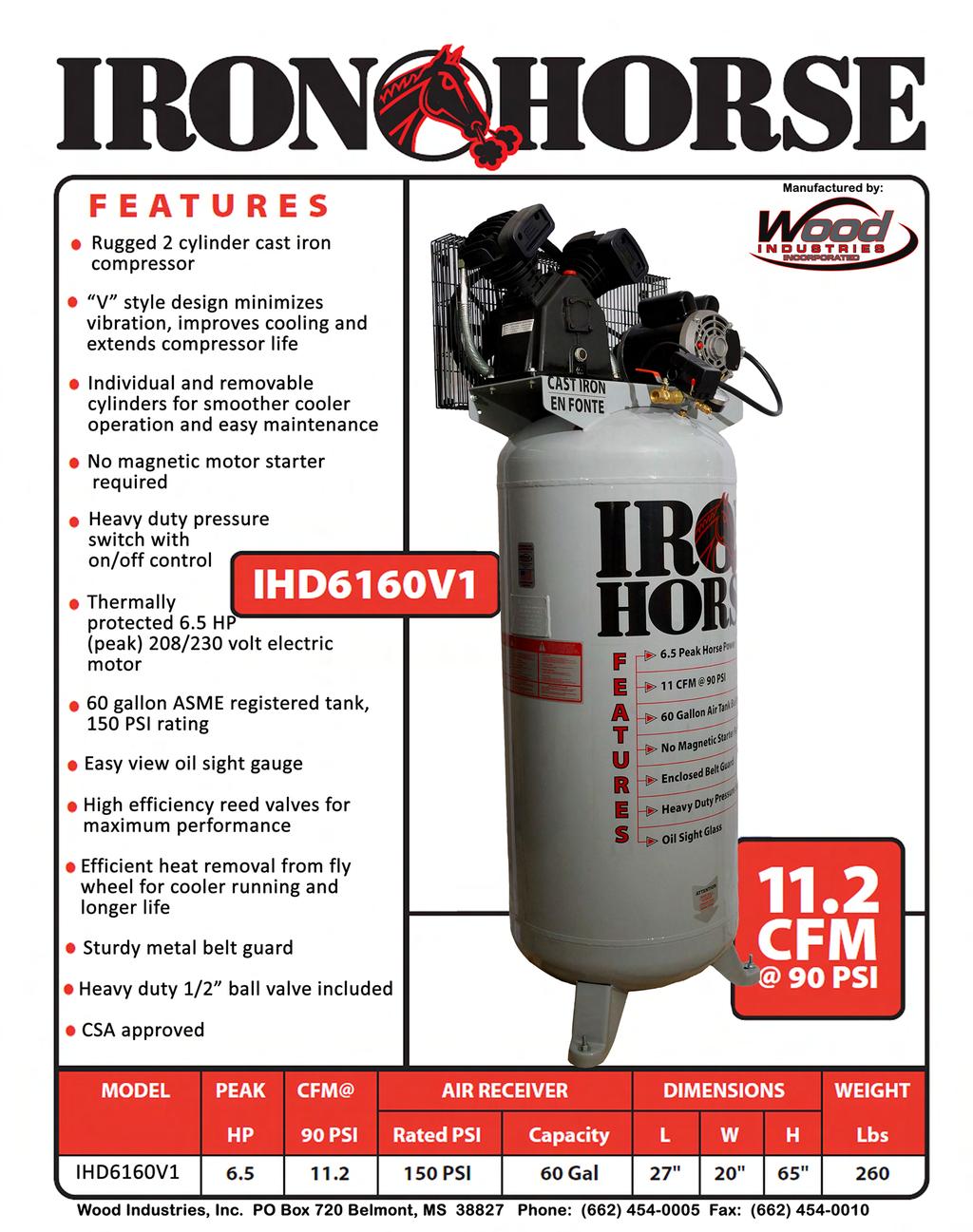
2 Iron Horse Air Compressor part breakdown - IHD6160V1 Item Description IHD6160V1 1 Compressor w/ Flywheel CC Discharge Tube w/ Fittings TU-23-AL 3 Pressure Gauge PG R 4 Air Receiver 60V20X48SPL 5 Drain Cock DC1/4 6 V-Belt 4L530 7 Belt Guard BGC 8 Motor - 1 Phase, 208/230V EM OSPL 9 Wiring Harness 12/3-24-C4 10 Check Valve CTF1/2X1/2 11 Pressure Switch 21UCBDB-CH 12 Motor Pulley MA38X5/8 13 Unloader Tube w/ Fittings TU1/4BLK 14 Safety Valve PSV1/ Ball Valve BV1/2MF Eagle Compressor Oil EAOIL10 IHD6160V1 Call for the Customer Service Department.

3 Item Description Qty Part # 1 Bolt for cylinder head 8 TB Washer for head bolt 8 TB Cylinder head 2 TB Air filter 2 TB Washer for air filter 4 TB Bolt for air filter 4 TB Head gasket 2 TB Valve seat 4 TB Aluminum gasket 2 TB Valve plate 4 TB Valve seat - cylinder gskt 2 TB Cylinder 2 TB Cylinder to crankcase nut 8 TB Cylinder - crank washer 8 TB Cylinder - crank screw 8 TB Cylinder - crank gasket 2 TB Compression rings 4 TB Ring kit (TB-30-17/19) 2 TB Oil control ring 2 TB Piston 2 TB Piston pin 2 TB Piston pin clip 2 TB Connecting rod 2 TB Oil splasher 2 TB Oil splasher 2 TB way connector pipe 2 TB Exhaust pipe nut 1 TB Elbow connector pipe 1 TB Intercooler tube 1 TB Bearing cover bolt 1 TB Bearing cover washer 4 TB Rear bearing cover 4 TB Oil sight glass gasket 1 TB Oil sight glass 1 TB Drain cock 1 TB Rear bearing cover gskt 1 TB Oil cap seal 1 TB Oil filler cap 1 TB Crankcase 1 TB Rear bearing 1 TB Crankshaft 1 TB Front bearing 1 TB Crankshaft oil seal 1 TB Front bearing cover gskt 1 TB Front shaft cover 1 TB Crankcase breather 1 TB Front cover wahser 4 TB Front cover bolt 4 TB Flywheel c/w fasteners 1 TB Flywheel washer 1 TB Flywheel copper washer 1 TB Flywheel bolt 1 TB Air filter element (CC2065) 2 TB Iron Horse Compressor breakdown sheet - CC2065
4 Stationary Compressor Operating Instructions Brands of stationary air compressors NOTICE Carefully read this instruction manual before attempting to operate this compressor. Model # Serial #
5 Brands of stationary air compressors Wear hearing protection. Wear eye protection. Wear respiratory protection. Read the instruction manual
6 TABLE OF CONTENTS Safety Precautions... 4 Cautions... 4 Air receiver... 4 Safety valve... 4 installation & operating instructions... 5 Installation... 5 Mounting... 5 Wiring... 5 Before operating the air compressor... 6 Compressor lubrication... 6 Filling compressor with oil... 7 Oil changes... 7 Engine lubrication... 7 Maintenance... 8 Checking Belt Tension... 8 operating your air compressor... 9 compressor maintenance schedule trouble shooting warranty En Français Brands of stationary air compressors Carefully read this instruction manual before attempting to operate this compressor.
7 SAFETY PRECAUTIONS Please familiarize yourself with the following information to prevent damage to your compressor unit and injury to the operator. CAUTIONS CAUTION The air compressor and motor will get hot while in operation. Never touch the discharge tubing, motor or compressor pump while in operation. The compressor operates automatically while the power is connected and turned on. WARNING Compressed air from the unit may contain hazardous fumes. Air produced by this compressor is not suitable for breathing purposes. Always use a respirator when spraying paint or chemicals, or when sandblasting. Always wear safety glasses or goggles when using compressed air. It is not practical or possible to warn you about all the hazards associated with operating or maintaining this equipment. You must use your own good judgment. AIR RECEIVER Over pressurizing the air receiver could cause personal injury or material damage. To protect from over pressurizing, a factory pre-set safety valve is installed. NEVER WELD, DRILL OR CHANGE THE AIR RECEIVER IN ANY WAY Any replacement parts should be purchased with the same specifications as the original equipment. Please contact the authorized dealer for replacement parts or specifications. SAFETY VALVE This valve is factory installed to prevent over pressurizing of the air receiver. It is factory set at a specific limit for your particular model, and should never be tampered with. Adjustment by user will automatically void the warranty. DO NOT REMOVE, MAKE ADJUSTMENTS TO OR SUBSTITUTE THIS VALVE! 4
8 INSTALLATION & OPERATION INSTALLATION Proper care, maintenance and lubrication ensures longevity. The compressor should always be level for proper lubrication. Use only in a clean, dry, and well-ventilated area. The compressor has heat dissipation fins for proper cooling. Keep the fins and other parts that collect dust clean. Do not place rags or other materials on top of the compressor, as this obstructs cooling and can be a fire hazard. MOUNTING Mount the compressor on a concrete pad or solid floor, making certain that the air receiver feet are level and that no stress is placed on the legs when the mounting nuts, if used, are tightened, shim feet if necessary. Severe vibrations will result when feet are uneven and drawn tightly to the floor, which can lead to welds cracking or fatigue failure of the air receiver. ALMOST ALL WELD CRACKS OR FATIGUE FAILURES ARE CAUSED BY IMPROPER INSTALLATION AND ARE NOT COVERED bywarranty. WIRING REGULATIONS REQUIRE THAT ALL WIRING BE DONE BY A LICENSED ELECTRICIAN, FAILURE TO DO SO COULD VOID YOUR WARRANTY. A) Single phase models with factory installed wiring between the electric motor and the pressure switch, - do not require a magnetic starter. B) Single phase models which are not pre wired between pressure switch and motor require a magnetic starter or combo switch (can be supplied by Wood Industries, Inc.) C) Three phase models require magnetic starters or combi-pressure switches (can be supplied by Wood Industries, Inc.) and are not factory Pre-wired in any way. 5
9 INSTALLATION & OPERATION WIRING... CONTINUED ALL WIRING INFORMATION IS STATED ON THE ELECTRIC MOTOR AND ON THE PRESSURE SWITCH OR PROVIDED WITH THE MAGNETIC STARTER, IF SUPPLIED. WIICustomER servicepersonnelcannot,by LAW, PROVIDE ANY WIRING INFORMATION. Any warranty claims for electrical components can only be considered when submitted with proof of proper electrical installation. BEFORE OPERATING THE AIR COMPRESSOR PLEASE CHECK THE FOLLOWING CAREFULLY: 1) Check to see that nuts and bolts are all snug. 2) Check if the quantity and quality of oil is correct. 3) If the intake filters are dirty, they should be replaced or cleaned. COMPRESSOR LUBRICATION ALWAYS CHECK THE OIL LEVEL AND QUALITY BEFORE START UP. DO NOT ADD OR CHANGE OIL WHILE THE UNIT IS RUNNING.USE ONLY RECOMMENDED NON-DETERGENT OIL. RECOMMENDED OIL. Eagle compressor oil: #EAOIL 10 (1 Litre) Eagle compressor oil: #EAOIL 40 (4 Litres). * Compressor originally filled with SAE 20W oil (ISO 68) 6
10 INSTALLATION & OPERATION COMPRESSOR LUBRICATION... CONTINUED Eagle compressor oil is a non-detergent mineral oil formulated with additives to help minimize carbon build-up, increase ring life and reduce oil consumption, for use at ambient temperatures of 0 to 30 C (32 F - 86 F). OTHER APPROVED OILS. Regular mineral oils can also be used in Wood Industries, Inc. compressors. Always use a non-detergent oil with the following specifications: AMBIENT TEMPERATURES AT SAE VISCOSITY ISO VISCOSITY POINT OF OPERATION -16 C TO 0 C (3.2 F - 32 F) SAE 10W ISO 32 1 C TO 26 C (33.8 F F) SAE 20W ISO 68 ABOVE 27 C (80.6 F) SAE 30W ISO 100 FILLING THE COMPRESSOR WITH OIL 1) Remove the oil filler plug 2) Slowly pour the proper oil into the pump crankcase. 3) Always keep oil level in the middle of the sight glass. OIL CHANGES INITIAL OIL CHANGE DUE AT 100 HOURS. CHANGE OIL EVERY 300 HOURS OR 3 MONTHS WHICHEVER COMES FIRST. 1) Remove the oil drain plug. Allow oil to drain completely. 2) Replace the oil drain plug. 3) Refill with the recommended oil to the proper level. ENGINE LUBRICATION (If Engine Driven) Check engine Owner s manual for lubrication and maintenance requirements.
11 INSTALLATION & OPERATION MAINTENANCE Before doing any maintenance or adjustments to your air compressor, the following safety precautions should be taken: TURN OFF AND LOCK OUT ELECTRIC POWER. DRAIN AIR RECEIVER AND AIR LINES OF AIR PRESSURE. CHECKING BELT TENSION (If belt driven) Adjust belt(s) so when pressure is applied at the center, there is approximately 1/2 slack (see diagram Figure A below). If the belt is installed too tight, the motor might be overloaded. This will cause the motor to overheat. If the belt is installed too loosely, it will slip and excessive wear and vibration will occur. Figure A Slight Bow Correct Tension Centre Distance Too Tight HOW TO INSTALL A NEW BELT IF REQUIRED: Too Loose 1) Disconnect power supply. 2) Remove belt guard. 3) Loosen motor bolts and slide motor toward compressor head just enough to allow old belt to be removed. 4) Install proper replacement belt. 5) Slide motor away from compressor head to provide recommended tension as shown in diagram (Figure A.) 6) Align belt using a straight edge ruler against pulley s edge. 7) Fasten motor bolts. 8) Ensure motor and compressor pulley s are secure. Re-check alignment. 9) Re-install belt guard and reconnect power supply. 10) Belt tension should be checked after 20 hours of operation. Check tension monthly thereafter. 8
12 OPERATING YOUR AIR COMPRESSOR EXTRA CARE SHOULD BE TAKEN TO AVOID PERSONAL INJURIES WITH AUTOMATIC CONTROLLED COMPRESSORS. 1) Check unit for any damage. All compressors are tested and inspected at the factory and supplied in perfect condition. Any damage is the freight carriers responsibility and you must notify the freight company immediately upon discovering any damage, and submit a claim. Ensure you have documented the damage on the waybill receipt if possible. 2) Check compressor installation and wiring 3) Turn on electric power and turn pressure switch knob to auto. Compressor should start running and air pressure should build up in the air receiver as evidenced by the air receiver pressure gauge. Make sure drain valve and outlet valve are closed. 4) When air receiver pressure reaches the pressure switch cut-out pressure, the compressor should stop automatically and you are now ready to start using the compressed air. As air is used, the pressure in the air receiver will drop and cause the pressure switch to close and this will automatically start the compressor. 5) The compressor will cycle automatically until you are finished using compressed air and the pressure switch knob is switched to off. DO NOT LEAVE THE POWER TO THE COMPRESSOR OVERNIGHT OR CONNECTED WHEN UNIT IS UNATTENDED 9
13 MAINTENANCE SCHEDULE DAILY OR BEFORE EACH USE WEEKLY CHECK OIL LEVEL. Drain condensation from air receiver. Check for any unusual noise or vibration. Be sure all nuts and bolts are tight. Turn off power. Clean dust and foreign matter from cylinder head, motor, fan blades, intercooler and air receiver. Clean air FILTER by opening air filter, removing filter element and cleaning it thoroughly with soapy water. Rinse thoroughly and allow to dry completely before assembly. Worn filters should be replaced. Check v-belts for wear. MONTHLY Inspect unit for leaks. Tighten joints if leaks are observed. Check v-belts for proper tension. Check compressor pulley and motor sheave are aligned and securely fastened. QUARTERLY OR 300 HOURS (Whichever comes first) Inspect the air receiver for corrosion or other damage. Change compressor oil. Replace air FILTER (more often if compressor is used near paint spraying operations or in dusty environments). 10
14 TROUBLE SHOOTING PROBLEM POSSIBLE CAUSE CORRECTIVE ACTION Will not start Incorrect power supply and/or wiring. Make sure power is turned on. (Consult with a licensed electrician). Drain air receiver. Air receiver is at full pressure. Low pressure Safety valve leaks. Replace safety valve. Drain cock open. Close drain cock. Loose tubes or fittings. Tighten fittings. Dirty or plugged air filter. Clean or replace as necessary. Defective unloader valve. Replace unloader valve. Oil in Too much oil in the crankcase. Drain oil and fill to proper level. discharge Compressor overheats Compressor loads & unloads or stops & starts excessively Improper oil viscosity. Compressor overheated. Restricted air filter. Worn piston rings. Dirty compressor head, cylinder or intercooler. Clogged inlet filter. Operating pressure too high. Low oil or wrong oil being used. Compressor cycle too long. Proper cycle is 50-60% on Stop/Start operation. Leaks in air system. Pressure switch differential adjusted too close. Defective compressor valves. Compressor too small for intended use. drain and replace oil Air pressure regulated too high. Clean or replace air filter. Replace piston rings. Clean with compressed air. Clean or replace as necessary. Reduce operating pressure. Drain and replace oil. Allow for longer rest between cycles. Check for leaks. Replace worn components as necessary. Make necessary adjustments. Replace valves. Upgrade to larger compressor. 11
15 12 TROUBLE SHOOTING PROBLEM POSSIBLE CAUSE CORRECTIVE ACTION Insufficient output, low discharge pressure Clogged inlet filter. Leaks in air lines, air valves, fittings, etc... Clean or replace as necessary. Replace worn components as necessary. Drive belts slipping. Tension V-belts. Drain valve left open. Close drain valve. Defective pressure gauge. Replace pressure gauge. Leaking head gasket. Replace head gasket. Motor stalls or blows breaker Water in crankcase oil gets dirty, rusty valves or cylinders Dirty or plugged inter cooler tubes. Pressure switch adjusted too low, or defective. Worn or defective compressor valves. Worn piston, worn out rings. Restrictive check valve. Faulty check valve. Valves incorrectly installed Drive belts too tight. Defective pressure switch. Defective Motor. Power being supplied by generator. Cycle too short; compressor does not operate long enough to vaporize condensed moisture during compression. System pressure leaking back through check valve when compressor is stopped. Wrong oil being used. Remove and clean inter cooler tubes. Make necessary adjustments. Replace valves. Replace worn parts. Clean check valve and replace if necessary. Replace check valve. Install valves correctly. Tension V-belts. Replace switch. Replace Motor. (Consult licensed electrician). Consult licensed electrician Allow for longer operating cycle. Check and replace check valve if necessary. Drain and replace with proper oil
16 TROUBLE SHOOTING PROBLEM POSSIBLE CAUSE CORRECTIVE ACTION Excessive vibration / compressor knocks Loose compressor, motor or engine guard. Compressor not level. Tighten components. Level compressor Compressor uses too much oil Feet bolts over tightened to floor. Excessive discharge pressure. Wrong oil being used. Loose flywheel, drive, pulley or drive belts. Worn connector rods, wrist pin or main bearings. Compressor valves loose or broken. Check valve knocks at low pressure. Clogged inlet filter. Wrong oil being used, wrong viscosity. Oil level too high. Crankcase breather valve malfunction. Compressor runs unloaded too long Compressor operating outside in cold conditions or inlet filter not protected against weather. Worn piston rings. Loosen feet bolts. Reduce operating pressure. Drain and replace with proper oil. Tighten loose components and check belts. Check and replace worn parts. Check and replace worn or broken valves.. Remove and clean check valve. Clean inlet filter or replace as necessary. Drain and replace oil. Fill compressor with oil to proper level. Replace crankcase breather. Increase load or stop compressor when not needed. Check for air leaks. Provide adequate protection against extreme weather conditions. Replace piston rings. Piston rings not seated. See instructions on page
17 TROUBLE SHOOTING PROBLEM POSSIBLE CAUSE CORRECTIVE ACTION Piston rings not seated. Allow 100 hours of normal operation for new rings to seat. Drain oil and refill with Eagle EAOIL oil or other approved oil. COMPRESSOR MAINTENANCE LOG DATE TYPE OF MAINTENANCE OR REPAIRS 14
18 standardwarranty Seller warrants products of its own manufacture against defects in workmanship and materials under normal use and service as follows: Brand COMPRESSORS: months from date of purchase. 12 Months 12months 24months PARTS: from date of sale 90 Days 90 Days 90 Days Wood Industries, Inc. (WII) warrants repaired or replaced parts of its own manufacture against defects in materials and workmanship under normal use and service for ninety (90) days or the remainder of the warranty on the product being repaired, whichever is longer. With respect to products not manufactured by WII, WII will, if practical, pass along the warranty of the original manufacturer. Notice of the alleged defect must be given to Seller in writing with all identifying details including serial number, model number, type of equipment and proof of purchase, within thirty (30) days of the discovery of same during the warranty period. WII s sole obligation on this warranty shall be, at its option, to repair, replace or refund the purchase price of any product or part thereof, which proves to be defective, F.O.B. WII shop. If requested by WII, such product or part thereof must be promptly returned to WII, freight prepaid for inspection. This warranty shall not apply and WII shall not be responsible nor liable for: a) Consequential, collateral or special losses or damages; b) Equipment conditions caused by normal wear and tear, abnormal conditions of use, accident, neglect or misuse of equipment, improper storage or damages resulting during shipment; c) Deviation from operating instructions, specification or other special terms of sale; d) Labor charges, loss or damage resulting from improper operation, maintenance or repairs made by person(s) other than WII or WII authorized service representative; e) Improper application of product. In no event shall WII be liable for any claims, whether arising from breach of contract or warranty of claims of negligence or negligent manufacture, in excess of purchase price. thiswarrantyisthesolewarrantyofwood INDUSTRIES, INC.and WARRANTIESwarranties,eXPRESSED,impliedinlaworimpliedin FACT, INCludinganywarrantiesofmerChantabilityandfitness FOR particularuse,areherebyspecificallyexcluded. 15
MODEL HP MAXIMUM RECEIVER MOTOR DIMENSIONS WEIGHT 100 PSI RATED PSI CAPACITY L-W-H (ins) (lbs) Toll Free
 (lbs) Toll Free") PUMP & COMPRESSOR LTD. Rugged compressor with cast iron cylinders V design minimizes vibration, improves cooling and extends compressor life Individual and removable cylinders for smoother and cooler operation
PUMP & COMPRESSOR LTD. Rugged compressor with cast iron cylinders V design minimizes vibration, improves cooling and extends compressor life Individual and removable cylinders for smoother and cooler operation
Portable Electric/Gas Compressor Operating Instructions
 Portable Electric/Gas Compressor Operating Instructions NOTICE Carefully read this instruction manual before attempting to operate this compressor. MODEL # SERIAL # 1-800-551-2406 TABLE OF CONTENTS Safety
Portable Oil Free Silent Series Compressor Operating Instructions
 Portable Oil Free Silent Series Compressor Operating Instructions NOTICE Carefully read this instruction manual before attempting to operate this compressor. MODEL # SERIAL # 1-800-551-2406 www.eaglecompressor.com
AIR COMPRESSOR OPERATING INSTRUCTION AND PARTS LIST
 AIR COMPRESSOR OPERATING INSTRUCTION AND PARTS LIST BELT TYPE IMPORTANT PLEASE MAKE CERTAIN THAT THE PERSON WHO IS TO USE THIS EQUIPMENT CAREFULLY READS AND UNDERSTANDS THESE INSTRUCTIONS BEFORE STARTING
NOTICE Carefully read this instruction manual and the engine manual before attempting to operate this compressor.
 www.makitatools.com NOTICE Carefully read this instruction manual and the engine manual before attempting to operate this compressor. WARNING: This product contains chemicals known to the State of California
SPECIFICATIONS: Tank Size: 80 gallons PUMP RPMs: 1050 CFM: 40PSI; 90 PSI Max Pressure: 150 PSI Thermal overload protection
 5HP 80 GALLON TWO STAGE COMPRESSOR Models: 51866, 51870 CALIFORNIA PROPOSITION 65 WARNING: You can create dust when you cut, sand, drill or grind materials such as wood, paint, metal, concrete, cement,
DISCLAIMER: SPECIFICATIONS:
 5HP 80 GALLON TWO STAGE COMPRESSOR Models: 7654 CALIFORNIA PROPOSITION 65 WARNING: You can create dust when you cut, sand, drill or grind materials such as wood, paint, metal, concrete, cement, or other
5180V2 5*80V2 7180V2 7*80V2
 Eagle Air Compressor part breakdown sheet - Two Stage Stationary Units (Vertical) Item Description 5180V2 5*80V2 7180V2 7*80V2 HPV05A HPV05A HPV05A TU-3/4-CU (2.5ft) TU-3/4-CU (2.5ft) TU-3/4-CU (2.5ft)
C T h e A d va n t a g e
 C The Advantage TABLE OF CONTENTS Introduction...1 Product Numbering System...1 Safety...2 Receiving and Inspection...2 Installation...2 Electrical...3 Parts Identification...7 Lubrication...9 Start-up...10
MODEL EGA220 OWNERS MANUAL
 1/4 MINI RATCHET MODEL EGA220 OWNERS MANUAL www.eaglecompressor.com 1-800-551-2406 READ THE ENTIRE MANUAL BEFORE PUTTING THIS TOOL IN SERVICE Limited Air Tool Warranty Wood Industries, Inc. warrants air
MODEL EGA200 OWNERS MANUAL
 3/8 RATCHET WRENCH MODEL EGA200 OWNERS MANUAL www.eaglecompressor.com 1-800-551-2406 READ THE ENTIRE MANUAL BEFORE PUTTING THIS TOOL IN SERVICE Limited Air Tool Warranty Wood Industries, Inc. warrants
1/4 ANGLE DIE GRINDER
 1/4 ANGLE DIE GRINDER MODEL EGA500 OWNERS MANUAL www.eaglecompressor.com 1-800-551-2406 READ THE ENTIRE MANUAL BEFORE PUTTING THIS TOOL IN SERVICE Limited Air Tool Warranty Wood Industries, Inc. warrants
PRODUCT NUMBERING SYSTEM SERIES PHASE. 1: Single Phase 3: Three Phase
 TABLE OF CONTENTS Product Numbering System and Specifications... Safety... Receiving and Inspection... Installation... Electrical...6 Start-up...7 INTRODUCTION The compressor you have purchased is a combination
OPERATING MANUAL AND PARTS LIST
 OPERATING MANUAL AND PARTS LIST MODEL GR309EDV ELECTRIC COMPRESSOR www.grip-rite.com TABLE OF CONTENTS Table of Contents... 1 Safety Symbols... 2 Safety Instructions... 3 Specifications... 5 Compressor
AIR COMPRESSOR INSTALLATION AND START-UP MANUAL. Table of Contents. Page# 1. INTRODUCTION 2. OWNER'S OBLIGATIONS 3. INSTALLATION AND START UP
 AIR COMPRESSOR INSTALLATION AND START-UP MANUAL Table of Contents Page# 1. INTRODUCTION 2. OWNER'S OBLIGATIONS 3. INSTALLATION AND START UP 4. INSTALLATION AND START UP / GAS 5. TROUBLE-SHOOTING GUIDE
MODEL EGA130 OWNERS MANUAL
 3/4 IMPACT WRENCH MODEL EGA130 OWNERS MANUAL www.eaglecompressor.com 1-800-551-2406 READ THE ENTIRE MANUAL BEFORE PUTTING THIS TOOL IN SERVICE Limited Air Tool Warranty Wood Industries, Inc. warrants air
ROYCE AIR COMPRESSOR 415VOLT/3 PHASE OPERATIONS MANUAL
 ROYCE AIR COMPRESSOR 415VOLT/3 PHASE OPERATIONS MANUAL PLEASE KEEP AND READ CAREFULLY BEFORE INSTALLING COMPRESSOR Table of Contents Unit Pictures & Descriptions 1 Warning 5 Installation 6 Starting, Run
STRAIGHT DIE GRINDER MODEL EGA530 OWNERS MANUAL
 STRAIGHT DIE GRINDER MODEL EGA530 OWNERS MANUAL www.eaglecompressor.com 1-800-551-2406 READ THE ENTIRE MANUAL BEFORE PUTTING THIS TOOL IN SERVICE Limited Air Tool Warranty Eagle warrants air tools of its
User s Manual D-Series Blowers and Exhausters
 User s Manual D-Series Blowers and Exhausters D05-1 ½ HP TEFC 115/230 VOLTS, 1 PH D05-3 ½ HP TEFC 208/230/460 VOLTS, 3 PH D10-1 1 HP TEFC 115/230 VOLTS, 1 PH D10-3 1 HP TEFC 208/230/460 VOLTS, 3 PH D15-1
D-Series Blowers and Exhausters
 Operation and Maintenance Manual D-Series MONOXIVENT - SOURCE CAPTURE SYSTEMS - info@ Oct. - 2015 MONOXVENT BLOWERS AND EXHAUSTERS D05-1 D05-3 D10-1 D10-3 D15-1 D15-3 D20-1 D20-3 D30-1 D30-3 ½ HP TEFC
WELDING FUME EXHAUSTERS & ARMS
 WELDING FUME EXHAUSTERS & ARMS The Ace 75 Series is our flexible and effective line of welding fume exhausters and extraction arms for shops that elect to exhaust their weld fumes outdoors instead of through
Pump Owner s Manual. PLEASE! Read All Instructions Carefully Before Installing Pump
 Pump Owner s Manual PLEASE! Read All Instructions Carefully Before Installing Pump Guarantee Associate Engineering Corporation warrants that pumps purchased from them will be free of defects in material
SPECIFICATIONS Horsepower: 1.5 HP Running Maximum PSI: 125 PSI Tank Capacity: 15 Gallons CFM: 6 40 PSI 5 90 PSI
 15 GALLON AIR COMPRESSOR Model: 7678 DO NOT RETURN TO STORE Please call 800-348-5004 for parts and service CALIFORNIA PROPOSITION 65 WARNING: You can create dust when you cut, sand, drill or grind materials
PRODUCT NUMBERING SYSTEM SERIES PHASE. HD: Heavy Duty (15,000+ hour life) SD: Standard Duty (5,000+ hour life) LD: Light Duty (2,000+ hour life)
 SD: Standard Duty (5,000+ hour life) LD: Light Duty (2,000+ hour life)") TABLE OF CONTENTS Product Numbering System...1 Safety...2 Receiving and Inspection...2 Installation...2 Electrical...3 Parts Identification...7 Lubrication...9 INTRODUCTION The compressor you have purchased
TABLE OF CONTENTS Product Numbering System...1 Safety...2 Receiving and Inspection...2 Installation...2 Electrical...3 Parts Identification...7 Lubrication...9 INTRODUCTION The compressor you have purchased
Single shot MODEL EGA700 OWNERS MANUAL
 Single shot AIR OPERATED GREASE GUN MODEL EGA700 OWNERS MANUAL www.eaglecompressor.com 1-800-551-2406 READ THE ENTIRE MANUAL BEFORE PUTTING THIS TOOL IN SERVICE Limited Air Tool Warranty Eagle warrants
SIP Direct Drive Oil-Lube Air Compressors - Operating & Maintenance Instructions
 SIP Direct Drive Oil-Lube Air Compressors - Operating & Maintenance Instructions Please read and fully understand the instructions in this manual before operation. Keep this manual safe for future reference.
PARTS MANUAL FOR TWO STAGE AIR COMPRESSOR
 PARTS MANUAL FOR TWO STAGE AIR COMPRESSOR SPECIFICATION CHART Model No. Horsepower Voltage-Single Phase Minimum Branch Circuit Requirement *Fuse Type Air Tank Capacity Approximate Cut-in Pressure Approximate
AIR COMPRESSOR AC5161B AC5161BP. User Manual
 AIR COMPRESSOR AC5161B AC5161BP User Manual table of contents table of contents Safety 6 Safety Rules 7 Safety Warnings Overview 11 Basic Air Compressor Components Assembly 13 Assembling the Compressor
READ AND SAVE THESE INSTRUCTIONS. Centrifugal Downblast Exhaust Fan Belt Driven for Roof & Wall Mounting
 READ AND SAVE THESE INSTRUCTIONS INSTALLATION, OPERATING INSTRUCTIONS & PARTS MANUAL Centrifugal Downblast Exhaust Fan Belt Driven for Roof & Wall Mounting Electrical wiring and connections should be done
READ AND SAVE THESE INSTRUCTIONS. High Velocity Restaurant-Duty Utility Set Belt Driven for Roof Mounting
 READ AND SAVE THESE INSTRUCTIONS INSTALLATION, OPERATING INSTRUCTIONS & PARTS MANUAL High Velocity Restaurant-Duty Utility Set Belt Driven for Roof Mounting Electrical wiring and connections should be
Routine Compressor Maintenance
 Establishing a regular, well-organized maintenance program and strictly following it is critical to maintaining the performance of a compressed air system. One person should be given the responsibility
OPERATIONS MANUAL LEVER CHAIN HOIST
 OPERATIONS MANUAL LEVER CHAIN HOIST IMPORTANT SAFETY INFORMATION Please read, understand and follow all safety information contained in these instructions prior to the use of this hoist. Retain these instructions
INSTRUCTION MANUAL: Industrial Series Piston Air Compressor. Model Number: V Part Number: L001128KNA
 INSTRUCTION MANUAL: Industrial Series Piston Air Compressor Model Number: V8051-335 Part Number: L001128KNA Pump Model: LP335 K335 Motor: 5 HP / 1 PH Air Tank: 80 Gal Vertical 1830 W. 15 th St. Houston,
KING CANADA 950W PORTABLE GENERATOR MODEL: KCG-951G INSTRUCTION MANUAL COPYRIGHT 2011 ALL RIGHTS RESERVED BY KING CANADA TOOLS INC.
 KING CANADA 950W PORTABLE GENERATOR MODEL: KCG-951G INSTRUCTION MANUAL COPYRIGHT 2011 ALL RIGHTS RESERVED BY KING CANADA TOOLS INC. WARRANTY & SERVICE INFORMATION 1-YEAR LIMITED WARRANTY FOR THIS 950W
INSTALLATION, OPERATION AND MAINTENANCE MANUAL WALL EXHAUST FANS BELT & DIRECT DRIVE XB, HV, HVA, ADD, DDS, DDP
 INSTALLATION, OPERATION AND MAINTENANCE MANUAL WALL EXHAUST FANS BELT & DIRECT DRIVE XB, HV, HVA, ADD, DDS, DDP The purpose of this manual is to aid in the proper installation and operation of the fans.
Electrical... 5 Start-up... 6 Digital Pressure Switch Programming and Instructions... 7 Maintenance... 8 PRODUCT NUMBERING SYSTEM PHASE SERIES
 TABLE OF CONTENTS Product Numbering System and Specifications... Safety... Receiving and Inspection... Installation... Electrical... 5 Start-up... 6 Digital Pressure Switch Programming and Instructions...
Electric Compressors US7580V B6000 FS002 MM36H675 SV25200 PS10M FIB02DC CV22 DT023 BG31184 BA67(2) S2AK61H
 S2AK61H") Electric Compressors 10 09 01 02 03 08 04 05 06 07 Illustration Part Description Number US660V US580V 1 Compressor B3800 T29S 2 Air Filter 2281000 4981000 3 Electric Motor M182711 M182703 4 Safety Valve
Electric Compressors 10 09 01 02 03 08 04 05 06 07 Illustration Part Description Number US660V US580V 1 Compressor B3800 T29S 2 Air Filter 2281000 4981000 3 Electric Motor M182711 M182703 4 Safety Valve
READ AND SAVE THESE INSTRUCTIONS. Centrifugal Upblast Exhaust Fan (Standard & High Pressure Exhaust) Belt Driven for Roof & Wall Mounting
 Belt Driven for Roof & Wall Mounting") READ AND SAVE THESE INSTRUCTIONS INSTALLATION, OPERATING INSTRUCTIONS & PARTS MANUAL Centrifugal Upblast Exhaust Fan (Standard & High Pressure Exhaust) Belt Driven for Roof & Wall Mounting Electrical wiring
READ AND SAVE THESE INSTRUCTIONS INSTALLATION, OPERATING INSTRUCTIONS & PARTS MANUAL Centrifugal Upblast Exhaust Fan (Standard & High Pressure Exhaust) Belt Driven for Roof & Wall Mounting Electrical wiring
6 Litre Oil-Less Air Compressor
 Operator s Manual 6 Litre Oil-Less Air Compressor WARNING! Before using this appliance, read the Operator s manual and follow all its safety rules and instructions. SPECIFICATION HWKAC1 1.1 kw / 1.5 HP
Air Compressor. Operating & Maintenance Instructions 1110 ENGINE DRIVEN - 1 -
 Air Compressor ENGINE DRIVEN Operating & Maintenance Instructions 1110-1 - Read these safety instructions before using the equipment. INTRODUCTION Thank you for purchasing this Clarke portable compressor.
AC3020B AC3030B PORTABLE AIR
 AC3020B AC3030B PORTABLE AIR operation manual CAUTION READ THIS MANUAL CAREFULLY before operating or servicing this air compressor, to familiarize yourself with the proper safety, operation, and standard
Adjustable Angled Incline Conveyor Owners Manual with Operating Instructions
 Adjustable Angled Incline Conveyor Owners Manual with Operating Instructions Revision 012211 Table of Contents Basic Conveyor Features 3 Getting Started 4 Setting Up the Incline Conveyor 5 Belt Removal
Hydraulic Bead Breaker Kit
 Hydraulic Bead Breaker Kit Owner s Manual WARNING: Read carefully and understand all ASSEMBLY AND OPERATION INSTRUCTIONS before operating. Failure to follow the safety rules and other basic safety precautions
Raydot LLC 24 Actuator (115 VOLT)
") Installation, Operation & Parts Manual Read carefully the information provided. Retain manual for future reference. Raydot LLC 24 Actuator (115 VOLT) 145 Jackson Ave. S. Cokato, MN 55321-USA (320) 286-2103
Installation, Operation & Parts Manual Read carefully the information provided. Retain manual for future reference. Raydot LLC 24 Actuator (115 VOLT) 145 Jackson Ave. S. Cokato, MN 55321-USA (320) 286-2103
OWNER S MANUAL EVOLUTION 3500, 4500, 5500, & 8500 SERIES PUMPS
 OWNER S MANUAL EVOLUTION 3500, 4500, 5500, & 8500 SERIES PUMPS IMPORTANT SAFETY INSTRUCTIONS When installing and using this electrical equipment, basic safety precautions should always be followed, including
REMY TECHNICAL SERVICE BULLETIN
 June 2018 REMY TECHNICAL SERVICE BULLETIN Remy Power Products is continuously adding technical training and technical information. We welcome suggestions. If there is something technical you would like
Installation and Operating Manual
 Installation and Operating Manual OIL-LESS RECIPROCATING AIR COMPRESSOR CIL Series INSTALLATION & OPERATING MANUAL OIL-LESS RECIPROCATING AIR COMPRESSOR TABLE OF CONTENTS Page 1 DESCRIPTIONS A. GENERAL
Air Compressor. Owner s Manual. Sonny's Enterprises, Inc Hiatus Road Tamarac, Florida v1
 Owner s Manual Sonny's Enterprises, Inc. 5605 Hiatus Road Tamarac, Florida 33321 16v1 *Table of Contents* WARNING *SAFETY REQUIREMENTS* WARNING... 3 *INTRODUCTION*... 5 Product Specifications... 6 Optional
SLR / SLR-S/N. Instruction Manual. Walrus America Inc
 SLR / SLR-S/N Instruction Manual Walrus America Inc 1. Installation and Connection 1.1. Pump Installation The pump should be sited in a well ventilated and frost-free position. The distance between pumps-motors
APCO CRF-100A RUBBER FLAPPER SWING CHECK VALVES
 APCO CRF-100A RUBBER FLAPPER SWING CHECK VALVES Instruction D12043 June 2016 DeZURIK Instructions These instructions provide installation, operation and maintenance information for APCO CRF-100A Rubber
SPLASH LUBRICATED AIR COMPRESSOR PUMPS
 Operating Instructions SPLASH LUBRICATED AIR COMPRESSOR PUMPS Airbase Industries designs and manufactures products for safe operation. However, operators and maintenance persons are responsibile for maintaining
24 Linear Actuator 115 Volts A.C. (Cat. # C430A)
") Installation, Operation & Parts Manual Read carefully the information provided. Retain manual for future reference. 24 Linear Actuator 115 Volts A.C. (Cat. # C430A) Page 1 of 8 IS10007.doc 11/15/06 IMPORTANT!
Installation, Operation & Parts Manual Read carefully the information provided. Retain manual for future reference. 24 Linear Actuator 115 Volts A.C. (Cat. # C430A) Page 1 of 8 IS10007.doc 11/15/06 IMPORTANT!
Model QP-10. QP Series. Parts Manual. Record of Change 200. Manual No December 2011 Edition
 QP Series Model Parts Manual Record of Change 200 This manual contains important safety information and must be made available to all personnel who operate and/or maintain this product. Carefully read
OWNER S MANUAL PRODUCT CODE: 2006T
 Jul-18 Product Code: 2006T OWNER S MANUAL PRODUCT CODE: 2006T HYDRAULIC PIPE BENDER 12,000KG Model Capacity Bending Die No of Attachments 12,000kg 1/2", 3/4", 1", 1-1/4", 1-1/2", 2" 6 Made in China to
Customer Support
 Portable auxiliary air tanks owner's Manual aux05 aux05a aux10 WWW.CALIFORNIAAIRTOOLS.COM Customer Support 1-866-409-4581 TAbLe OF CONTeNTS INTROduCTION IntroductIon Important Safety InStructIonS components
INSTALLATION, OPERATION AND MAINTENANCE MANUAL WALL EXHAUST FANS BELT DRIVE XBL FANS
 INSTALLATION, OPERATION AND MAINTENANCE MANUAL WALL EXHAUST FANS BELT DRIVE XBL FANS The purpose of this manual is to aid in the proper installation and operation of the fans. These instructions are intended
Model Series. PumpAgents.com - buy pumps and parts online ELECTRIC BILGE PUMPS. Model Series FEATURES SPECIFICATIONS STANDARD MODELS
 PumpAgents.com - Click here for Pricing/Ordering Model 36600-Series ELECTRIC BILGE PUMPS FEATURES Self-Priming Diaphragm Design Allows Dry Running Quiet Operation Built-in Hydraulic Pulsation Dampener
PARTS LIST FOR AIR COMPRESSORS AC-SH20-2 AC-SV20-2 ENGINE OIL GRADE: HONDA: SAE 10W-30. Below 40 F=SAE 10W-30 ENGINE OIL CAPACITY:
 PARTS LIST FOR AIR COMPRESSORS AC-SH20-2 AC-SV20-2 ENGINE OIL GRADE: HONDA: SAE 10W-30 VANGUARD: Above 40 F=SAE30 Below 40 F=SAE 10W-30 ENGINE OIL CAPACITY: HONDA: 37 oz. VANGUARD: 40 oz. MAXIMUM PRESSURE
ULTRA QUIET & OIL FREE MP100LF MP120LF
 ULTRA QUIET & OIL FREE AIR COMPRESSOR MOTOR/PUMP OwnER'S MAnUAL MP100LF MP120LF WWW.CALIFORNIAAIRTOOLS.COM Customer Support 1-866-409-4581 TAbLe OF CONTeNTS INTROduCTION IntroductIon 2 IMPortant SaFety
Jet Fans. Instruction Manual READ AND SAVE THESE INSTRUCTIONS WARRANTY
 Jet Fans Instruction Manual READ AND SAVE THESE INSTRUCTIONS WARRANTY All Leader Fan products are guaranteed to be free from defects of workmanship or material and to function satisfactorily when properly
BCFS Belt Driven Centrifugal Filtered Supply Fans
 BCFS Belt Driven Centrifugal Filtered Supply Fans INSTALLATION, OPERATION & MAINTENANCE MANUAL IM-4300 August 2014 Throughout this manual, there are a number of HAZARD S that must be read and adhered to
DIRECT-DRIVE PRESSURE WASHERS
 DIRECT-DRIVE PRESSURE WASHERS PJG SERIES PRESSURE WASHER MANUFACTURED BY: PJG-2002B PJG-2502-6.5B PJG-3002B PJG-4002B INTRODUCTION Thank you for purchasing a Mancorp Pressure Washer. This manual covers
Lubricator Gun: 10,000 psi (700 bar) Maximum Delivery Pressure when disconnected from Dispenser
 Maximum Delivery Pressure when disconnected from Dispenser") INSTRUCTIONS-PARTS LIST 30 455 INSTRUCTIONS This manual contains important warnings and information. READ AND KEEP FOR REFERENCE. Rev. C Supercedes B Hand-Operated Portable Grease Dispenser Buckshot Luber
INSTRUCTIONS-PARTS LIST 30 455 INSTRUCTIONS This manual contains important warnings and information. READ AND KEEP FOR REFERENCE. Rev. C Supercedes B Hand-Operated Portable Grease Dispenser Buckshot Luber
OPERATING SERVICE MAINTENANCE MANUAL
 OPERATING SERVICE MAINTENANCE MANUAL ALL-STAR ROCKING PISTON COMPRESSOR AND VACUUM PUMP Registered by one or more of these standards agency ISO RoHS 9001 Compliant CE Read through carefully and understand
1. GENERAL INFORMATION WARRANTY- PARTS - SERVICE SERIAL # ITEM # Printed in Canada Issue Date: October 2010 Revision 12
 TABLE OF CONTENTS SECTION PAGE 1 GENERAL INFORMATION 2 2 SAFETY GUIDELINES 3 3 OPERATION 4 3.1 How the Compressor Works 4 3.1.1 Components 4 3.1.2 Controls 5 3.1.3 Inlet Air System 6 3.1.4 Discharge System
Read this entire manual before operation begins.
 Read this entire manual before operation begins. Record below the following information which is located on the serial number data plate. Serial No. Model No. Date of Installation Contents Specifications.............
HR-20P Pneumatically Controlled Pressure Regulator
 HR-20P Pneumatically Controlled Pressure Regulator Instruction and Service Manual Hydroplex Corporation 230 West Gloria Switch Rd. Lafayette, LA 70507 337-233-0626 www.hydroplexpumps.com I. General Instructions
900 SERIES SPLIT CASE FIRE PUMP REPAIR PARTS INDEX
 900 SERIES SPLIT CASE FIRE PUMP REPAIR PARTS INDEX Read and understand the pump and motor instructions before attempting to install, disassemble or repair the pump. Part # AF-03-326 2015 Pentair Ltd. 01/30/15
COMPAK PRODUCTS QUEENSLAND M2S TO M310
 COMPAK PRODUCTS QUEENSLAND AUSTRALIAN MADE AND OWNED MODEL M2S TO M310 SALES AND SERVICES SINCE 1956 COMPAK PRODUCTS QUEENSLAND 999 IPSWICH ROAD MOOROOKA QUEENSLAND 4105 PHONE (07) 3892 5433 FAX (07) 3848
ATK LIMITED WARRANTY FOR REMANUFACTURED ENGINES
 ATK LIMITED WARRANTY FOR REMANUFACTURED ENGINES ATK and its subsidiaries distributes a broad range of new, recycled, remanufactured and truck replacement products through its company owned and operated
Models GED/GSD, DFE/DFS & DDE/DDS Installation, Operation, and Maintenance Manual
 Models GED/GSD, DFE/DFS & DDE/DDS Installation, Operation, and Maintenance Manual Direct Drive Sidewall Propeller Fans (Exhaust and Supply) READ AND SAVE THESE INSTRUCTIONS The purpose of this manual is
STRUT SPRING COMPRESSOR
 OWNER S MANUAL PRODUCT CODE: 1221T STRUT SPRING COMPRESSOR Capacity Stroke Spring Coil Spring Spring Coil Net Weight (Maximum) Thickness Length Diameter 1,000kg 330mm 10-18mm 210-570mm 100-158mm 36kg Made
WARRANTY REGISTRATION INSTRUCTIONS
 WARRANTY REGISTRATION INSTRUCTIONS YOU MUST REGISTER THE PRODUCT TO ACTIVATE/RECIEVE WARRANTY 1 LIMITED WARRANTY STANDARD WARRANTY TERMS * Gasoline Engines Automobiles and Light Trucks Gasoline Engines
TALCO FIRE SYSTEMS. LSF Start-Up Instructions. 1) IMPORTANT: Inspect the unit for damage. Report any damage to the freight carrier immediately.
 IMPORTANT: Inspect the unit for damage. Report any damage to the freight carrier immediately.") LSF Start-Up Instructions 1) IMPORTANT: Inspect the unit for damage. Report any damage to the freight carrier immediately. 2) PRE-START-UP: Be sure there is water in the pump. Bleed air at all high points
LSF Start-Up Instructions 1) IMPORTANT: Inspect the unit for damage. Report any damage to the freight carrier immediately. 2) PRE-START-UP: Be sure there is water in the pump. Bleed air at all high points
Model QP-5. QP Series. Parts Manual. Record of Change 203. Manual No December 2011 Edition
 QP Series Model Parts Manual Record of Change 203 This manual contains important safety information and must be made available to all personnel who operate and/or maintain this product. Carefully read
AC2T & AC2T-ES INDUSTRIAL GASOLINE AIR COMPRESSOR
 AC2T & AC2T-ES INDUSTRIAL GASOLINE AIR COMPRESSOR INDUSTRIAL GAS AIR COMPRESSOR OPERATOR S MANUAL IT IS ETREMELY IMPORTANT TO READ AND UNDERSTAND THE ENTIRE CONTENTS OF THIS OPERATOR S MANUAL BEFORE ATTEMPTING
2SHE Series Direct-Drive Shutter Fans
 Operational Instruction and Parts Manual Item #: 481810 Rev Date: 101414 2SHE Series Direct-Drive Shutter Fans Fantech, Inc. and Systemair Mfg. certify that the ventilators shown herein are licensed to
INSTALLATION VARIABLE FREQUENCY DRIVE THREE PHASE ALX SERIES SPUN ALUMINUM EXHAUSTERS
 SPUN ALUMINUM EXHAUSTER OPERATION INSTRUCTIONS AND PARTS MANUAL READ AND SAVE THESE INSTRUCTIONS The purpose of this manual is to aid in the proper installation and operation of the blowers. These instructions
GARDEN HOSE UTILITY PUMP
 GARDEN HOSE UTILITY PUMP MODEL #HPP360, HPP12V, 473707 MODEL #HPP360, 473707 MODEL #HPP12V ATTACH YOUR RECEIPT HERE Purchase Date SAFETY INFORMATION Please read and understand this entire manual before
Installation and Maintenance Manual
 Installation and Maintenance Manual WorldWide Helical Inline Speed Reducers This operation manual includes important information for the installation, assembly, operation and maintenance of the WorldWide
OWNER/OPERATOR MANUAL. Airmotor effective dia. in. 2.5
 MODELS 282050, 282716 & 283513 AIR OPERATED CHASSIS PUMP SERIES A OWNER/OPERATOR MANUAL SPECIFICATIONS Airmotor effective dia. in. 2.5 Airinlet Material outlet 1/4 NPTF 1/4 NPTF Liquid to Air Pressure
INSTALLATION AND MAINTENANCE MANUAL FORM #PM-122 REV A 12/09
 HAND CRANK WELDING CABLE REEL: SERIES 100WC COXREELS The technical data and images which appear in this manual are for informational purposes only. NO WARRANTIES, EXPRESS OR IMPLIED, INCLUDING WARRANTIES
Pro Shot Grease Dispense Valve
 Instructions Parts List Pro Shot Grease Dispense Valve 309032J For high pressure grease dispense. 8000 psi (55 MPa, 552 bar) Maximum Working Pressure Model No. 242055, Series B, 1/4 npt Fluid Inlet Model
6L Oil-less Air Compressor 53103
 6L Oil-less Air Compressor 53103 Operating Instructions Please read and save these instructions before attempting to assemble, install, operate or maintain the product. Protect yourself and others by observing
STANDARD WARRANTY TERMS *
 ATK NORTH AMERICA S PRODUCT WARRANTY POLICY APRIL 2012 LIMITED WARRANTY ATK will repair or replace, free of charge, any part(s) of the product that is defective in material or workmanship or both. Transportation
Heavy Duty Four Wheeled Walker
 Heavy Duty Four Wheeled Walker Weight Capacity: 500 lbs. ITEM # W1802 Made in China 2011 ESSENTIAL MEDICAL SUPPLY, INC. Manufactured for Orlando, FL 32822 -- SAVE THESE INSTRUCTIONS -- Do not attempt to
HA/HAB Fiberglass Wall Mount Ventilators
 HA/HAB Fiberglass Wall Mount Ventilators INSTALLATION, OPERATION & MAINTENANCE MANUAL IM-3100 August 2015 Throughout this manual, there are a number of HAZARD S that must be read and adhered to in order
TURBOCHARGER Toyota Celica DESCRIPTION OPERATION TURBOCHARGING SYSTEMS All Models
 TURBOCHARGER 1988 Toyota Celica 1988 TURBOCHARGING SYSTEMS All Models DESCRIPTION Most models use a water-cooled turbocharger, mounted directly to the exhaust manifold with a wastegate assembly attached
TRAILER WINCH MODELS ST315 AND ST712. General Safety (Continued) Description. Unpacking. General Safety Information.
 Description. Unpacking. General Safety Information.") OPERATION AND MAINTENANCE MANUAL TRAILER WINCH READ CAREFULLY BEFORE ATTEMPTING TO ASSEMBLE, INSTALL, OPERATE OR MAINTAIN THE PRODUCT DESCRIBED. PROTECT YOURSELF AND OTHERS BY OBSERVING ALL SAFETY INFORMATION.
OPERATION AND MAINTENANCE MANUAL TRAILER WINCH READ CAREFULLY BEFORE ATTEMPTING TO ASSEMBLE, INSTALL, OPERATE OR MAINTAIN THE PRODUCT DESCRIBED. PROTECT YOURSELF AND OTHERS BY OBSERVING ALL SAFETY INFORMATION.
VT Oil-Free Range Operators Handbook
 VT Oil-Free Range Operators Handbook Covering Models:- VT7 / VT7D VT10 / VT10D VT200 / VT200D VT300 / VT300D VT00 / VT00D BAMBI AIR COMPRESSORS LTD 12 Thimble Mill Lane Heartlands Birmingham B7 HT Tel:
430B SERIES HORIZONTAL SPLIT CASE PUMP
 430B SERIES TWO Stage - DIAGONALLY HORIZONTAL SPLIT CASE PUMP REPAIR PARTS INDEX NOTE! Read and understand the pump and motor instructions before attempting to install, disassemble or repair the pump.
PF-4000, PF-4010, PF-4210 MULTI-PURPOSE ENGINE
 PF-4000, PF-4010, PF-4210 MULTI-PURPOSE ENGINE Date 09-26-01 Supplier To The Outdoor Power Equipment Industry ISM, Inc. 1028 4 th Street SW Auburn, WA 98001 Phone: (253) 333-1200 Fax: (253) 333-1212 WWW.TANAKA-USA.COM
INSTRUCTIONS AND SERVICE MANUAL WITH PARTS LIST
 CMP SERIES CPM15-15B (25905F300) CPM15-15B-H/D (25905F301) CPM18-15B (25905F303) CPM18-15B-H/D (25905F304) INDUSTRIAL PUMPS INSTRUCTIONS AND SERVICE MANUAL WITH PARTS LIST NOTE! To the installer: Please
Table 6-1. Problems and solutions with pump operations. No Fluid Delivery
 Table 6-1. and solutions with pump operations No Fluid Delivery Fluid level in the reservoir is low. Oil intake pipe or inlet filter is plugged. Air leak in the inlet line prevents priming or causes noise
AIR COMPRESSOR IDENTIFICATION
 AIR COMPRESSOR IDENTIFICATION For information and questions contact customer service at 1-800-232-1195. Please fill out the information below and have it accessible prior to calling. For the Serial Number
Pressure Roller with 24-inch Fixed Extension - For application of architectural paints and coatings -
 Instructions Important Safety Instructions Read all warnings and instructions in this manual. Save these instructions. 311082D Pressure Roller with 24-inch Fixed Extension - For application of architectural
Air Compressor PP10ND PPH10ND PP15ND PPH15ND. Operating & Maintenance Instructions
 Air Compressor PP10ND PPH10ND PP15ND PPH15ND Operating & Maintenance Instructions 1002 SPECIFICATIONS PP10ND PPH10ND PP15ND PPH15ND Part Number 2090940 2090960 209080 2090100 WARNING! DO NOT ATTEMPT TO
INSTALLATION AND MAINTENANCE MANUAL FORM #PM-126 REV A 12/09
 HAND CRANK & MOTORIZED POWER CORD REELS: SERIES 1125PC SERIES: 1125PC HAND CRANK SERIES: 1125PC MOTORIZED COXREELS The technical data and images which appear in this manual are for informational purposes
Scania Used Vehicle Extended Driveline Warranty
 Scania Used Vehicle Extended Driveline Warranty Scania Dealers supply Approved Used Vehicles with the Scania Used Vehicle Extended Driveline Warranty to first purchasers from the Dealership subject to
Read this entire manual before operation begins.
 Read this entire manual before operation begins. Record below the following information which is located on the serial number data plate. Serial No. Model No. Date of Installation Contents Specifications.............