Installation and Operating Manual
|
|
|
- Tamsin Henry
- 5 years ago
- Views:
Transcription
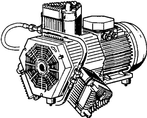
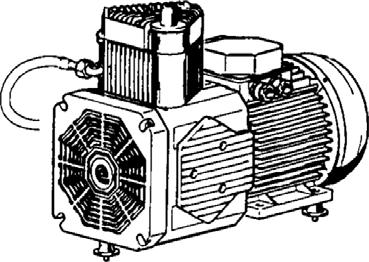
1 Installation and Operating Manual OIL-LESS RECIPROCATING AIR COMPRESSOR CIL Series
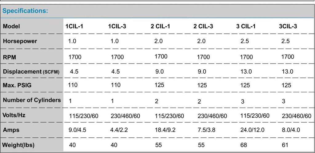
2 INSTALLATION & OPERATING MANUAL OIL-LESS RECIPROCATING AIR COMPRESSOR TABLE OF CONTENTS Page 1 DESCRIPTIONS A. GENERAL 2 B. PISTON & PISTON RINGS 2 C. HOURMETER 2 D. CONDENSATE DRAIN VALVE 2 2 INSTALLATION A. RECEIVING THE UNIT 2 B. INSTALLATION SITE 3 C. VENTILATION 3 D. WIRING 3 E. PIPING 3 F. SAFETY VALVES 4 3 OPERATION A. BEFORE START UP 4 B. START-UP AND OPERATION 4 4 MAINTENANCE SCHEDULE 5 5 TECHNICAL DRAWINGS A. DIMENSIONS 6 B. SPECIFICATIONS 7 C. 1CIL Parts Breakdown 8 D. 2CIL Parts Breakdown 9 E. 3CIL Parts Breakdown 10 6 WARRANTY 11 NOTE: THIS OPERATION AND MAINTENANCE MANUAL IS A GENERAL GUIDELINE FOR AIRTECH OILLESS RECIPROCATING AIR COMPRESSORS AND SHOULD BE USED IN CONJUNCTION WITH SPECIFIC MANUALS FOR THE SUPPLIED AIR COMPRESSOR ALONG WITH AS BUILT WIRING DIAGRAMS.
3 1 DESCRIPTIONS A. GENERAL The Airtech Oilless Reciprocating Air Compressor has advanced compressor technology through the development of a completely oilless unit. The Airtech Reciprocating Compressor is available in single stage models. Continuously lubricated, sealed bearings provide oil-free compressed air and long compressor life. The finned flywheel and temperature reducing aluminum alloy piston create lower operating temperatures. B. PISTON AND PISTON RINGS The Airtech oilless reciprocating compressor pistons are made of a high-strength aluminum alloy using the most advanced technology available. These heat reducing pistons eliminate the effect of excessive grease leakage at the wrist pin bearing. Teflon rings reduce wear and provide self lubrication. C. HOURMETER The hourmeter on the oilless compressor indicates the actual number of hours the unit has been in operation. The hourmeter is also used to determine maintenance and service timing. An hourmetermust be installed with every oilless compressor. D. CONDENSATE DRAIN VALVE A condensate drain valve must be installed on any tank used to allow removal of the liquid which will collect during compressor operations *NOTICE: Drain liquid from tank daily. 2 INSTALLATION A. RECEIVING THE UNIT Immediately upon receipt of the oilless compressor, the unit should be inspected for any damage which may have occured in shipment. The compressor nameplate should be checked to see if the unit is the correct model and voltage as ordered. DANGER: Breathable Air Warning This compressor/pump is NOT equipped and should NOT be used as is to supply breathing quality air. For any application or air for human consumption, you must fit the compressor/pump with suitable in-line safety and alarm equipment. This additional equipment is necessary to properly filter and purify the air to meet minimal specifications for Grade D breathing as described in Compressed Gas Association Commodity Specification G , OSHA 29 CFR , and/or Canadian Standards Associations (CSA). DISCLAIMER OF WARRANTIES - In the event the compressor/pump is used for the purpose of breathing air application and proper in-line safety and alarm equipment is not simultaneously used, existing warranties are void, and Airtech disclaims any liability whatsoever for any loss, personal injury or damage. 2
4 B. INSTALLATION SITE 1. The oilless compressor must be located in a clean, well lit and well ventilated area. 2. The area should be free of excessive dust, toxic or flammable gases and moisture. 3. Never install the compressor where the ambient temperature is higher than 105 F or where humidity is high. 4. Clearance must allow for safe, effective inspection and maintenance. Minimum Clearances Above 24 Drive belt side 12 Other sides If necessary, use metal shims or leveling pads to level the compressor. Never use wood to shim the compressor. C. VENTILATION 1. If the oilless compressor is located in a totally enclosed room, an exhaust fan with access to outside air must be installed. 2. Never restrict the cooling fan exhaust air. 3. Never locate the compressor where hot exhaust air from other heat generating units may be pulled into the unit. D. WIRING All electrial hook-ups must be performed by a qualified electrician. Installations must be in accordance with local and national electircal codes. Use solderless terminals to connect the electric power source. E. PIPING 1. Make sure the piping is lined up without being strained or twisted when assembling the piping for the compressor. 2. Appropriate expansion loops or bends should be installed at the compressor to avoid stresses caused by changes in hot and cold conditions. 3. Piping supports should be anchored separately from the compressor to reduce noise and vibration. 4. Never use any piping smaller than the compressor connection. 3
5 5. Use flexible hose to connect the outlet of the compressor to the piping so that the vibration of the compressor does not transfer to the piping. F. SAFETY VALVES Tank mounted compressors are shipped from the factory with safety valves installed in the tank manifold. The flow capacity of the safety valve is equal to or greater than the capacity of the compressor. 1. The pressure setting of the safety valve must be no higher than the maximum working pressure of the tank. 2. Safety valves should be placed ahead of any possible blockage point in the system, i.e. shutoff valve. 3. Avoid connecting the safety valve with any tubing or piping. 4. Manually operate the safety valve every six months to avoid sticking or freezing. 3 OPERATION Airtech oilless single stage compressors operate at a maximum pressure of 125 PSIG. Compressor RPM s are established by Airtech based on horsepower and operating pressure. A. BEFORE START UP 1. Make sure all safety warnings, labels and instructions have been read and understood before continuing. 2. Remove any shipping materials, brackets, etc. 3. Confirm that the electric power source and ground have been firmly connected. 4. Be sure all pressure connections are tight. 5. Check to be certain all safety relief valves, etc., are correctly installed. 6. Check that all fuses, circuit breakers, etc., are the proper size. 7. Make sure the inlet filter is properly installed. 8. Confirm that the drain valve is closed. 9. Visually check the rotation of the compressor pump. If the rotation is incorrect, have a qualified electrician correct the motor wiring. B. START-UP AND OPERATION 1. Follow all the procedures under Before start-up before attempting operation of the compressor. 4
6 2. Switch the electric source breaker on. 3. Open the tank discharge valve completely. 4. Check that the compressor operates without excessive vibration, unusual noises or leaks. 5. Close the discharge valve completely. 6. Check the discharge pressure. Also, make sure the air pressure rises to the designated pressure setting by checking the discharge pressure gauge. 7. Check the operation of the pressure switch or the pilot valve for continuous run units by opening the stop valve and confirming the compressor starts or reloads as pressure drops. *NOTICE: If the compressor rotates in reverse for more than five seconds when the compressor is turned OFF, the check valve needs to be cleaned or replaced. Switch the breaker OFF if the compressor is not to be used for a long period of time. *NOTICE: Units are equipped with head unloaders for continuous operation. 4 MAINTENANCE SCHEDULE Operating Hours Item Action Needed ,000 15,000 20,000 Remarks Tank Drain moisture Daily 2500 Inlet Air Filter Replace (Every 2,500 hours or less) Blower Fan Clean Compressor Fins Clean (Every 2,500 hours or less) Bearings Replace Compression Rings Replace Wrist Pin Bearing Regrease Piston Set Replace Unloader Spring Replace (continuous operating pumps only) V-belt Inspect, replace *Note 3 Pressure Switch Confirm operation Magnetic Starter Inspect Replace if contact points deteriorated Safety Valve Confirm operation (Every 2,500 hours or less) Pressure Gauge Inspect (Every 2,500 hours or less) Inspect Replace NOTES: 1. Inspect and perform maintenance periodically according to maintenance schedule. 2. The maintenance schedule relates to the normal operating conditions. If the circumstances and load condition are adverse, shorten the cycle time and do maintenance accordingly. 3. * The tension of he V-blet should be adjsuted during the initial stage and inspected every 1,500 hours afterwards. Proper belt tension for 3/4 to 3 HP units is 12 lbs./.5" deflection; for 5 to 20 HP units, 16 lbs./.5" deflection. 5

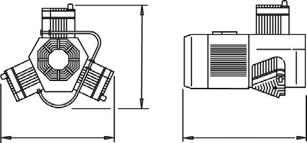
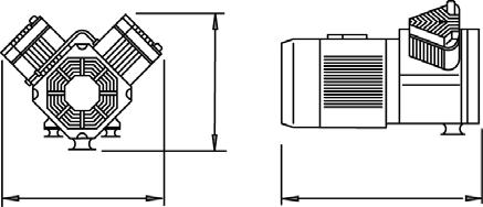
7 Dimensions: (Inches) 1CIL: 2CIL: 3CIL:
8 7
9 8
10 9
11 10
12 WARRANTY PERIOD A. New Airtech system, installed and maintained according to manufacturers recommendation, will be warranted against defects in material and workmanship for a period of two (2) years from the date of shipment from the factory. B. An extension of a warranty period will require written approval from Airtech and may require and inspection of the equipment by an Airtech representative. The cost for extending a warranty period will be determined at the time of the request. WARRANTY STATUS A. Before proceeding with any warranty service, the selling distributor or the authorized Airtech service agent must first contact Airtech to (a) verify that the equipment is within the warranty period, (b) verify that the repair service provided is covered under warranty and (c) to initiate the Warranty Claim Form number. B. Final approval of all warranty service claims and credits will be determined by Airtech. C. It is the responsibility of the selling distributor to start-up the Airtech system and insure proper operation. AIRTECH, INC. System Warranty Policy E. In the event of a warranty equipment replacement, the warranty on the replaced part shall not exceed the time remaining on the original parts warranty period. F. The effect of normal wear and tear, corrosion or oxidation are excluded from this warranty. G. Airtech will only pay warranty labor charges when the service performed satisfactorily corrects the problem. H. The following list of conditions are viewed as the responsibility of the end user or selling distributor and are not covered under warranty: 1. Improper installation (including location) of: a. piping b. electrical wiring or voltage supply c. extreme environmental conditions 2. Any incidental damage. 3. Instructions of any type concerning Airtech equipment. 4. Adjustments including switches, controls, belts, tightening bolts, etc Improper operation. 6. Maintenance or normal wear items such as air or oil filter lubricants. 7. Overtime premium. 8. Rental equipment or lost production. WARRANTY RESPONSIBILITY A. Responsibility for warranty service belongs to the selling distributor or the authorized Airtech service agent. B. Only authorized Airtech service agents will be compensated for performing warranty service work. WARRANTY LIMITATIONS AND EXCLUSIONS A. The obligation of Airtech is limited under this warranty to repair or replace without charge, F.O.B. factory, any part that has proven to have an original manufactured defect. B. This warranty shall not apply to any equipment which has been subjected to misuse, neglect or accident: nor shall it apply to any equipment which has been repaired or altered by any person not authorized by Airtech. C. Components and/or accessories manufactured by other vendors (such as motors, etc.) will be warranted by the original manufacturer. The customer may be required to take the defective part to that manufacturer s authorized repair facility for replacement or repair. D. The maximum allowable warranty repair cost must not exceed 50% of the normal distributor cost of a replacement unit unless written authorization is obtained from Airtech. REMIBURSEMENT FOR WARRANTY SERVICE WORK A. Reimbursement for warranty service work provided will be as follows: $40.00 per labor hour $0.40 per mile B. Parts The cost of parts used from the distributor s stock will be credited at the normal distributor cost. Any part needed for warranty repair may be ordered from Airtech with an accompanying purchase order. This order will receive priority handling and will be invoiced and credited back on the Warranty Claim Form. All parts which were replaced under warranty must be returned to Airtech freight prepaid, with the appropriate Warranty Claim Form number clearly marked on the box and packing slip. FILING A WARRANTY CLAIM A. The Airtech Warranty Claim Form must be filled out with all information requested before any consideration can be given to the claim. B. Attach a copy or the Authorized Service Agent s work order to the form. C. Submit the Warranty Claim Form within 60 days of the equipment failure date in order to receive warranty consideration. 11

 Fax: +86-755-81730986 www.airtechchina.")
13 150 South Van Brunt St. Englewood, NJ Tel: Fax: SOUTH 2211 Newmarket Parkway Marietta, GA Tel: Fax: WEST 42 Digital Drive #9 Novato, CA Tel: Fax: CHINA 2nd Building, Jiangbian Second Industrial Park Songgang Town, Bao'an District Shenzhen, China Tel: (Ext.8018) Fax: Amsterdamstraße 16 D Schweinfurt, Germany Tel: +49 (0) Fax: +49 (0) Hijo de J. Planas Escubós, S.L. Av. de l'aixernador, Argentona (Barcelona) - Spain Tel: (+34) Fax: (+34)
Installation and Operating Manual OIL-LESS RECIPROCATING AIR COMPRESSOR
 Installation and Operating Manual OIL-LESS RECIPROCTING IR COMPRESSOR INSTLLTION & OPERTING MNUL OIL-LESS RECIPROCTING IR COMPRESSOR TLE OF CONTENTS Page 1 DESCRIPTIONS. GENERL 2. PISTON & PISTON RINGS
High Pressure Scroll Tankmount/Basemount Air Compressors
 High Pressure Scroll Tankmount/Basemount Air Compressors Please read and save these instructions. Read carefully before attempting to assemble, install, operate or maintain the product described. Protect
Installation and Operating Manual
 Installation and Operating Manual L-Series Vacuum Pumps Models L/H400C-L/H630C INSTALLATION & OPERATING MANUAL L/H-SERIES SINGLE STAGE ROTARY VANE VACUUM PUMPS L/H400C-L/H630C Please read the manual before
Description. Safety Guidelines. Breathable Air Warning. Lubricated Compressor Pumps
 Please read and save these instructions. Read carefully before attempting to assemble, install, operate or maintain the product described. Protect yourself and others by observing all safety information.
Models & Options Lubrication. 1/2 Through 10 Hp Models 1Ø 3Ø 1/2 Through 10 Hp Models 1Ø and 3Ø
 P U R E A I R T E C H N O L O G Y Climate Control Duplex Please read and save these instructions. Read carefully before attempting to assemble, install, operate or maintain the product described. Protect
Read this entire manual before operation begins.
 Read this entire manual before operation begins. Record below the following information which is located on the serial number data plate. Serial No. Model No. Date of Installation Contents Specifications.............
Figure 1 - OTS HP Simplex Air Compressor, 30 Gallon, 460 V Starter and Auto Drain. Models & Options Lubrication
 P U R E A I R T E C H N O L O G Y Oilless Tankmount Simplex Please read and save these instructions. Read carefully before attempting to assemble, install, operate or maintain the product described. Protect
Description. Specifications (Series) Oilless Reciprocating Air Compressor Pumps
 Oilless Reciprocating Air Compressor Pumps") Please read and save these instructions. Read carefully before attempting to assemble, install, operate or maintain the product described. Protect yourself and others by observing all safety information.
Please read and save these instructions. Read carefully before attempting to assemble, install, operate or maintain the product described. Protect yourself and others by observing all safety information.
Lubricated Compressor Pumps
 Please read and save these instructions. Read carefully before attempting to assemble, install, operate or maintain the product described. Protect yourself and others by observing all safety information.
C T h e A d va n t a g e
 C The Advantage TABLE OF CONTENTS Introduction...1 Product Numbering System...1 Safety...2 Receiving and Inspection...2 Installation...2 Electrical...3 Parts Identification...7 Lubrication...9 Start-up...10
SPECIFICATIONS: Tank Size: 80 gallons PUMP RPMs: 1050 CFM: 40PSI; 90 PSI Max Pressure: 150 PSI Thermal overload protection
 5HP 80 GALLON TWO STAGE COMPRESSOR Models: 51866, 51870 CALIFORNIA PROPOSITION 65 WARNING: You can create dust when you cut, sand, drill or grind materials such as wood, paint, metal, concrete, cement,
Portable Electric/Gas Compressor Operating Instructions
 Portable Electric/Gas Compressor Operating Instructions NOTICE Carefully read this instruction manual before attempting to operate this compressor. MODEL # SERIAL # 1-800-551-2406 TABLE OF CONTENTS Safety
PARTS MANUAL FOR TWO STAGE AIR COMPRESSOR
 PARTS MANUAL FOR TWO STAGE AIR COMPRESSOR SPECIFICATION CHART Model No. Horsepower Voltage-Single Phase Minimum Branch Circuit Requirement *Fuse Type Air Tank Capacity Approximate Cut-in Pressure Approximate
ADI-125/750 ADI-125/1500 ADI-125/2500
 Manufacturer of Dimensions TM Inverters 4467 White Bear Parkway St. Paul, MN 55110 Phone: 651-653-7000 Fax: 651-653-7600 E-mail: inverterinfo@sensata.com Web: www.dimensions.sensata.com 121094B OWNERS
PRODUCT NUMBERING SYSTEM SERIES PHASE. 1: Single Phase 3: Three Phase
 TABLE OF CONTENTS Product Numbering System and Specifications... Safety... Receiving and Inspection... Installation... Electrical...6 Start-up...7 INTRODUCTION The compressor you have purchased is a combination
Read this entire manual before operation begins.
 Read this entire manual before operation begins. Record below the following information which is located on the serial number data plate. Serial No. Model No. Date of Installation Contents Specifications.............
AIR COMPRESSOR OPERATING INSTRUCTION AND PARTS LIST
 AIR COMPRESSOR OPERATING INSTRUCTION AND PARTS LIST BELT TYPE IMPORTANT PLEASE MAKE CERTAIN THAT THE PERSON WHO IS TO USE THIS EQUIPMENT CAREFULLY READS AND UNDERSTANDS THESE INSTRUCTIONS BEFORE STARTING
Reach ins, Freeezers & Refrigerators Installation & Operation Manual
 Reach ins, Freeezers & Refrigerators Installation & Operation Manual BSR23 BSF23 BSR49 BSF49 BSR72 BSF72 IMPORTANT SAFETY INSTRUCTIONS (SAVE THESE INSTRUCTIONS) Visit us on the web at www.blueairinc.com
OWNERS MANUAL JANUARY 2007 ISO
 Manufacturer of Dimensions TM Inverters 4467 White Bear Parkway St. Paul, MN 55110 Phone: 651-653-7000 Fax: 651-653-7600 E-mail: inverterinfo@sensata.com Web: www.dimensions.sensata.com 121231B OWNERS
DISCLAIMER: SPECIFICATIONS:
 5HP 80 GALLON TWO STAGE COMPRESSOR Models: 7654 CALIFORNIA PROPOSITION 65 WARNING: You can create dust when you cut, sand, drill or grind materials such as wood, paint, metal, concrete, cement, or other
Description. Glossary of Terms. Specifications. Glossary of Terms (Continued) Medical Tankmount Compressor
 Medical Tankmount Compressor") Please read and save these instructions. Read carefully before attempting to assemble, install, operate or maintain the product described. Protect yourself and others by observing all safety information.
Please read and save these instructions. Read carefully before attempting to assemble, install, operate or maintain the product described. Protect yourself and others by observing all safety information.
DIRECT-DRIVE PRESSURE WASHERS
 DIRECT-DRIVE PRESSURE WASHERS PJG SERIES PRESSURE WASHER MANUFACTURED BY: PJG-2002B PJG-2502-6.5B PJG-3002B PJG-4002B INTRODUCTION Thank you for purchasing a Mancorp Pressure Washer. This manual covers
24/3000H-3PH 24/4500H-3PH 24/6000H-3PH
 Manufacturer of Dimensions TM Inverters 4467 White Bear Parkway St. Paul, MN 55110 Phone: 651-653-7000 Fax: 651-653-7600 E-mail: inverterinfo@sensata.com Web: www.dimensions.sensata.com 120015D OWNERS
PRODUCT NUMBERING SYSTEM SERIES PHASE. HD: Heavy Duty (15,000+ hour life) SD: Standard Duty (5,000+ hour life) LD: Light Duty (2,000+ hour life)
 SD: Standard Duty (5,000+ hour life) LD: Light Duty (2,000+ hour life)") TABLE OF CONTENTS Product Numbering System...1 Safety...2 Receiving and Inspection...2 Installation...2 Electrical...3 Parts Identification...7 Lubrication...9 INTRODUCTION The compressor you have purchased
TABLE OF CONTENTS Product Numbering System...1 Safety...2 Receiving and Inspection...2 Installation...2 Electrical...3 Parts Identification...7 Lubrication...9 INTRODUCTION The compressor you have purchased
TERMS OF USE TERMS AND CONDITIONS. Plumbing and Heating Products (PL-WR)
") TERMS OF USE 1. Watts pricing and product data is subject to change without notice and such changes supersede all previous versions. 2. Watts data is to be used as provided. Watts is not responsible for
TERMS OF USE 1. Watts pricing and product data is subject to change without notice and such changes supersede all previous versions. 2. Watts data is to be used as provided. Watts is not responsible for
Enclosed Electric Rotary Screw Compressor Installation Guide
 Enclosed Electric Rotary Screw Compressor Installation Guide Air compressors should only be installed trained installation personnel call 800-531-9656 to find a local trained. Warning: Read all installation
Users Manual Certified Series Direct Drive Pump 1-7 LPM
 Users Manual Certified Series Direct Drive Pump 1-7 LPM Safety, Operating, Installation, and Maintenance Instructions 600 S 56 th Street #9 Chandler, AZ 85226 Phone: 480-507-6478 Fax: 480-838-2232 www.fogco.com
Description. Specifications. High Pressure Scroll Tankmount/Basemount Air Compressors. Name of Tool
 High Pressure Scroll Tankmount/Basemount Air Compressors Name of Tool Please read and save these instructions. Read carefully before attempting to assemble, install, operate or maintain the product described.
DC to AC Power Inverters
 Manufacturer of Dimensions TM Inverters 4467 White Bear Parkway St. Paul, MN 55110 Phone: 651-653-7000 Fax: 651-653-7600 E-mail: inverterinfo@sensata.com Web: www.dimensions.sensata.com ISO 9001:2000 Certified
See Warranty on page 6 for important information about commercial use of this product.
 See Warranty on page 6 for important information about commercial use of this product. Operating Instructions WL6000 Series Please read and save these instructions. Read carefully before attempting to
DC to AC Power Inverters
 Manufacturer of Dimensions TM Inverters 4467 White Bear Parkway St. Paul, MN 55110 Phone: 651-653-7000 Fax: 651-653-7600 E-mail: inverterinfo@sensata.com Web: www.dimensions.sensata.com 121114C OWNERS
"SPOAU" DEDICATED 100% OUTSIDE AIR UNITS Self Contained Single Package or Split System Units
 "SPOAU" DEDICATED 100% OUTSIDE AIR UNITS Self Contained Single Package or Split System Units Spinnaker Industries Inc. Model Series SPOAU 100% Outdoor Air Systems shall be factory assembled, wired and
Air Compressor. Owner s Manual. Sonny's Enterprises, Inc Hiatus Road Tamarac, Florida v1
 Owner s Manual Sonny's Enterprises, Inc. 5605 Hiatus Road Tamarac, Florida 33321 16v1 *Table of Contents* WARNING *SAFETY REQUIREMENTS* WARNING... 3 *INTRODUCTION*... 5 Product Specifications... 6 Optional
Operators Manual. Recirculating Chiller /06/08
 Operators Manual Recirculating Chiller 110-197 11/06/08 Table of Contents Section 1. General Information 1.1 Warranty 1.2 Unpacking 1.3 Package Contents 1.4 Description of the Recirculating Chiller 1.5
PVI 1800/PVI Residential/Commercial Grid-Tied Photovoltaic Inverter WARRANTY MANUAL. Subject to Change REV , Solectria Renewables
 PVI 1800/PVI 2500 WARRANTY MANUAL Residential/Commercial Grid-Tied Photovoltaic Inverter 2009, Solectria Renewables Subject to Change REV 10.09 1 Product Warranty & RMA Policy 1.1 Warranty Policy The Solectria
MIL-24/2600Q MIL-24/3200DQ
 Manufacturer of Dimensions TM Inverters 4467 White Bear Parkway St. Paul, MN 55110 Phone: 651-653-7000 Fax: 651-653-7600 E-mail: inverterinfo@sensata.com Web: www.dimensions.sensata.com 121473B OWNER'S
Oilless Tankmount Duplex
 Please read and save these instructions. Read carefully before attempting to assemble, install, operate or maintain the product described. Protect yourself and others by observing all safety information.
HI-FLOW FUEL RAIL. Installation Instructions for Scion tc & xb AEM Fuel Rail AN Hose adaptor
 HI-FLOW FUEL RAIL Installation Instructions for 08-10 Scion tc & xb 25-170 AEM Fuel Rail 2-661 -6 AN Hose adaptor AEM Performance Electronics INC. 2205 126 TH Street, Unit A Hawthorne, CA. 90250 Phone:
HP190SL Series Slimline Radon Fans
 Installation and Operation Manual Item #: 412843 Rev Date: 070113 HP190SL Series Slimline Radon Fans United States 10048 Industrial Blvd., Lenexa, KS, 66215 Tel.: 800.747.1762 Fax: 800.487.9915 Canada
Dimensions 12/800N 12/1200N D. DC to AC Power Inverters. OWNERS MANUAL for Models: OWNERS MANUAL April ISO 9001:2000 Certified Company
 Manufacturer of Dimensions Inverters 4467 White Bear Parkway St. Paul, MN 55110 Phone: 651-653-7000 Fax: 651-653-7600 E-mail: inverterinfo@sensata.com Web: www.dimensions.sensata.com OWNERS MANUAL April
Electrical... 5 Start-up... 6 Digital Pressure Switch Programming and Instructions... 7 Maintenance... 8 PRODUCT NUMBERING SYSTEM PHASE SERIES
 TABLE OF CONTENTS Product Numbering System and Specifications... Safety... Receiving and Inspection... Installation... Electrical... 5 Start-up... 6 Digital Pressure Switch Programming and Instructions...
Description. Specifications. Scroll Tankmount/Basemount Air Compressors
 Scroll Tankmount/Basemount Air Compressors Please read and save these instructions. Read carefully before attempting to assemble, install, operate or maintain the product described. Protect yourself and
Electric Reciprocating Compressor. Installation Guide
 Electric Reciprocating Compressor Installation Guide Air compressors should only be installed trained installation personnel call 800-531-9656 to find a local trained. Warning: Read all installation steps,
Open Frame Reciprocating Gas/Diesel Engine Driven Compressor. Installation Guide
 Open Frame Reciprocating Gas/Diesel Engine Driven Compressor Installation Guide call 800-531-9656 to find a local trained air compressor service technician. Warning: Read all installation steps, compressor
PVI 60KW, PVI 82KW, PVI 95KW
 PVI 60KW PVI 82KW PVI 95KW WARRANTY MANUAL Commercial, Grid-Tied Photovoltaic Inverters 2008, Solectria Renewables LLC Subject to Change DOC-020099 rev 024 1 1 Product Warranty & RMA Policy Warranty Policy
Read this entire manual before operation begins.
 Read this entire manual before operation begins. Record below the following information which is located on the serial number data plate. Serial No. Model No. Date of Installation Contents Specifications.............
advanced FLOW engineering Instruction Manual P/N: /
 advanced FLOW engineering Instruction Manual P/N: 46-70040 / 46-70042 Make: Dodge/RAM Model: 2500 Year: 2003-2013 Engine: L6-5.9L (td)/6.7l (td) Make: Dodge/RAM Model: 3500 Year: 2003-2012 Engine: L6-5.9L
NECO Pumping Systems
 INSTALLATION OPERATION & MAINTENANCE INSTRUCTIONS For Your NECO Pumping Systems PACKAGED CIRCULATING SYSTEM THIS COMPLETELY ASSEMBLED, TESTED, PACKAGED CIRCULATING SYSTEM IS OF THE HIGHEST QUALITY AND
INSTALLATION INSTRUCTIONS SINGLE HORIZONTAL ACCESS DOOR PANTRY INSERT MANUAL
 INSTALLATION INSTRUCTIONS MODEL #88972 SINGLE HORIZONTAL ACCESS DOOR PANTRY INSERT MANUAL TABLE OF CONTENTS PAGE # INSTALLATION INSTRUCTIONS...................2 CABINET LOCATION GUIDELINES...2 REGULAR
Raydot LLC 24 Actuator (115 VOLT)
") Installation, Operation & Parts Manual Read carefully the information provided. Retain manual for future reference. Raydot LLC 24 Actuator (115 VOLT) 145 Jackson Ave. S. Cokato, MN 55321-USA (320) 286-2103
Installation, Operation & Parts Manual Read carefully the information provided. Retain manual for future reference. Raydot LLC 24 Actuator (115 VOLT) 145 Jackson Ave. S. Cokato, MN 55321-USA (320) 286-2103
ALITA LINEAR AIR PUMP OPERATION & MAINTENANCE MANUAL. AL- Model Number Date Code / Serial Number Date of Purchase
 ALITA LINEAR AIR PUMP OPERATION & MAINTENANCE MANUAL AL- Model Number Date Code / Serial Number Date of Purchase LIMITED WARRANTY ALITA warrants to the original retail consumer purchaser ( Customer ) that
Iron Horse Air Compressor part breakdown - IHD6160V1 Item Description IHD6160V1 IHD6160V1 Call for the Customer Service Department.
 Iron Horse Air Compressor part breakdown - IHD6160V1 Item Description IHD6160V1 1 Compressor w/ Flywheel CC2065 2 Discharge Tube w/ Fittings TU-23-AL 3 Pressure Gauge PG200-2.5R 4 Air Receiver 60V20X48SPL
D-Series Blowers and Exhausters
 Operation and Maintenance Manual D-Series MONOXIVENT - SOURCE CAPTURE SYSTEMS - info@ Oct. - 2015 MONOXVENT BLOWERS AND EXHAUSTERS D05-1 D05-3 D10-1 D10-3 D15-1 D15-3 D20-1 D20-3 D30-1 D30-3 ½ HP TEFC
ActuLink ABS Module - ABS-MOD-400
 Installation Instructions ActuLink ABS Module - ABS-MOD-400 For more information on the installation and operation of Tuson s towable ABS system, consult the installation and operations manuals for the
Utility Distribution Systems Installation, Operation, and Maintenance Manual
 Utility Distribution Systems Installation, Operation, and Maintenance Manual RECEIVING AND INSPECTION Upon receiving unit, check for any interior and exterior damage, and if found, report it immediately
Blue Air. Commercial Refrigeration Inc. Installation & Operation Manual Glass Door Countertop Refrigerator
 Blue Air Commercial Refrigeration Inc. Installation & Operation Manual Glass Door Countertop Refrigerator Please read this manual completely before installing or operating this unit! BAGR7 Blue Air reserves
SUNC3000 / Item #40885
 SUNC3000 / Item #40885 AUTOMATIC POOL COVER PUMP OPERATIONS MANUAL WWW.SUNRUNNERPOOL.COM 1 . Performance GPH of Water @ Total Feet Of Lift MODEL HP Max. Lift 0 ft. 5 ft. 10 ft. 15 ft. 20 ft. SUNC3000 1/3
Badger Truck Refrigeration, Inc. Warranty Policy
 Badger Truck Refrigeration, Inc. Warranty Policy The manufacturer warrants each new heater, air conditioner or part to be free from defects in materials and workmanship under conditions of normal use and
Operating Instructions for PAC800 Battery Charger
 Operating Instructions for PAC800 Battery Charger General Safety The charger may only be used for the specified battery types. This battery charger is supplied with pre-set charging curves that are adapted
Blue Air. Commercial Refrigeration Inc. Installation & Operation Manual Chef Bases
 Blue Air Commercial Refrigeration Inc. Installation & Operation Manual Chef Bases Please read this manual completely before installing or operating this unit! BACB53 BACB71 BACB74 BACB83 BACB86 BACB96
Smart Battery Charger GPC-35-MAX GPC-45-MAX GPC-55-MAX GPC-75-MAX GPC-100-MAX. Owner s Manual
 Smart Battery Charger GPC-35-MAX GPC-45-MAX GPC-55-MAX GPC-75-MAX GPC-100-MAX Owner s Manual Table of Contents Important Safety Instructions 2 Features 3 Installation Guidelines 5 Warranty 8 1.0 Important
7.3L POWERSTROKE BANJO BOLT KIT Fits L Powerstroke Diesel. Installation Guide
 7.3L POWERSTROKE BANJO BOLT KIT Fits 94-03 7.3L Powerstroke Diesel Installation Guide INSPECT CONTENTS OF THIS KIT THOROUGHLY BEFORE STARTING THE INSTALLATION PROCESS! IF YOU FIND A PROBLEM WITH YOUR PACKAGE:
User s Manual D-Series Blowers and Exhausters
 User s Manual D-Series Blowers and Exhausters D05-1 ½ HP TEFC 115/230 VOLTS, 1 PH D05-3 ½ HP TEFC 208/230/460 VOLTS, 3 PH D10-1 1 HP TEFC 115/230 VOLTS, 1 PH D10-3 1 HP TEFC 208/230/460 VOLTS, 3 PH D15-1
SUNC1200 / ITEM #40882 SUBMERSIBLE UTILITY PUMP OPERATIONS MANUAL
 SUNC1200 / ITEM #40882 SUBMERSIBLE UTILITY PUMP OPERATIONS MANUAL WWW.SUNRUNNERPOOL.COM Performance Model HP GPH of Water @ Total Feet Of Lift 0 ft. 5 ft. 10 ft. 15 ft. 20 ft. 25 ft. Max. Lift SUNC1200
Atlas PV-9WP Addendum
 Atlas PV-9WP Addendum 9,000 lb. Capacity Two-Post Overhead Lift The Atlas PV-9WP above ground hoist is 6 inches wider than the Atlas PV-9P, giving it an overall width of 141 (11 9 ) and a drive thru width
H.S. MACHINERY RING COMPRESSORS
 OPERATION & PARTS MANUAL Thank you for purchasing an H.S Machinery Limited Regenerative Blower. This product is manufactured under strict ISO-9001-2000 quality control guidelines to ensure your satisfaction.
INSTALLATION AND OPERATING MANUAL
 Dated: May 10, 2001 INSTALLATION AND OPERATING MANUAL MODEL: T30-Y TURBOTWIN Engine Air Starter From Tech Development Inc AN96-425 6800 Poe Ave. Dayton OH 45414 Tel: (937) 898-9600 Fax: (937) 898-8431
SOLAR DASH CHARGING SYSTEM USER GUIDE
 SOLAR DASH CHARGING SYSTEM Doc 1.01 INST049 INSTALLATION STEP 1 Place 20 watt solar panel in the dash of the vehicle facing up. Note: For ideal results position the vehicle in a manner in which the solar
Installation & Operation Manual Chef Base
 Installation & Operation Manual Chef Base Please read this manual completely before installing or operating this unit! BACB53 BACB53M BACB71 BACB71M BACB74 BACB74M BACB83 BACB83M BACB86 BACB86M BACB96
TPHK Series Immersible Pump
 TPHK Series Immersible Pump Instruction Manual ISO 9001 Certified Walrus America Inc 234867 EC Declaration of Conformity Manufacturer: Walrus Pump Co., Ltd. Address: No. 83-14, Dapiantou, Sanjhih Township,
User s Manual for Tennessee Chill Box System P/N CB8000
 User s Manual for Tennessee Chill Box System P/N CB8000 Read and understand all instructions before using this product. Open carton carefully and inspect product for damage caused by carrier. If any damage
OWNERS MANUAL JANUARY 2007 ISO
 Manufacturer of Dimensions TM Inverters 4467 White Bear Parkway St. Paul, MN 55110 Phone: 651-653-7000 Fax: 651-653-7600 E-mail: inverterinfo@sensata.com Web: www.dimensions.sensata.com OWNERS MANUAL JANUARY
Model BP6150. Triplex Ceramic Plunger Pump Operating Instructions/ Manual
 Model BP6150 Triplex Ceramic Plunger Pump Operating Instructions/ Manual Contents: Installation Instructions: page 2 Pump Specs: page 3 Exploded View: page 4 Parts List / Kits Torque Specifications: page
advanced FLOW engineering Instruction Manual P/N: &
 advanced FLOW engineering Instruction Manual P/N: 46-70031 & 46-70032 Make: Dodge Model: 2500/3500 Year: 94-02 Engine: L6-5.9L (td) Cummins Make: Dodge Model: 2500/3500 Year: 94-02 Engine: V8-5.9L & V10-8.0L
READ AND SAVE THESE INSTRUCTIONS. Centrifugal Downblast Exhaust Fan Belt Driven for Roof & Wall Mounting
 READ AND SAVE THESE INSTRUCTIONS INSTALLATION, OPERATING INSTRUCTIONS & PARTS MANUAL Centrifugal Downblast Exhaust Fan Belt Driven for Roof & Wall Mounting Electrical wiring and connections should be done
60 Watt Industrial LED Low Bay Light
 60 Watt Industrial LED Low Bay Light Owner s Manual WARNING: Read carefully and understand all ASSEMBLY AND OPERATION INSTRUCTIONS before operating. Failure to follow the safety rules and other basic safety
SIP Direct Drive Oil-Lube Air Compressors - Operating & Maintenance Instructions
 SIP Direct Drive Oil-Lube Air Compressors - Operating & Maintenance Instructions Please read and fully understand the instructions in this manual before operation. Keep this manual safe for future reference.
Open Frame Gas/Diesel Engine Driven Rotary Screw Compressor. Installation Guide
 Open Frame Gas/Diesel Engine Driven Rotary Screw Compressor Installation Guide Air compressors should only be installed trained installation personnel call 800-531-9656 to find a local trained. Warning:
INSTRUCTIONS SMOKE BLOWER WITH HONDA ENGINE PART NUMBER
 1 INSTRUCTIONS SMOKE BLOWER WITH HONDA ENGINE PART NUMBER 303-568 CHERNE INDUSTRIES INCORPORATED 1-800-THE PLUG 5700 LINCOLN DRIVE (1-800-843-7584) MINNEAPOLIS, MN 55436-1695 FAX: 1-800-843-7585 www.cherneind.com
Installation and Operation Manual
 Installation and Operation Manual * Read all installation instruction and warranty information prior to beginning installation * XeVision HID landing and taxi lights are for experimental aircraft only
24 Linear Actuator 115 Volts A.C. (Cat. # C430A)
") Installation, Operation & Parts Manual Read carefully the information provided. Retain manual for future reference. 24 Linear Actuator 115 Volts A.C. (Cat. # C430A) Page 1 of 8 IS10007.doc 11/15/06 IMPORTANT!
Installation, Operation & Parts Manual Read carefully the information provided. Retain manual for future reference. 24 Linear Actuator 115 Volts A.C. (Cat. # C430A) Page 1 of 8 IS10007.doc 11/15/06 IMPORTANT!
WELDING FUME EXHAUSTERS & ARMS
 WELDING FUME EXHAUSTERS & ARMS The Ace 75 Series is our flexible and effective line of welding fume exhausters and extraction arms for shops that elect to exhaust their weld fumes outdoors instead of through
Aqua Ultraviolet Sunami Series Pumps 1/3HP, 3/4HP, 3HP, 4HP, 5HP
 TM 42371 Avenida Alvarado Temecula, CA 92590 TOLL FREE (800) 454-2725 TEL (951) 296-3480 FAX (951) 296-3490 www.aquauv.com Aqua Ultraviolet Sunami Series Pumps 1/3HP, 3/4HP, 3HP, 4HP, 5HP Sunami Warranty
Owner s Manual GLASSLINED PUMP TANK
 Owner s Manual GLASSLINED PUMP TANK ANSI/NSF 61 Annex G Thank You for purchasing a pump tank. Properly installed and maintained, it should give you years of trouble free service. If you should decide that
Installation and Operating Manual. L-Series Vacuum Pumps
 Installation and Operating Manual L-Series Vacuum Pumps Models L12 L305 INSTALLATION & OPERATING MANUAL L-SERIES SINGLE STAGE ROTARY VANE VACUUM PUMPS L12 - L305 Please read the manual before operating
APCO CRF-100A RUBBER FLAPPER SWING CHECK VALVES
 APCO CRF-100A RUBBER FLAPPER SWING CHECK VALVES Instruction D12043 June 2016 DeZURIK Instructions These instructions provide installation, operation and maintenance information for APCO CRF-100A Rubber
INSTALLATION AND OPERATING MANUAL
 Publication T3-76, Rev. 1 Dated: May 9, 21 INSTALLATION AND OPERATING MANUAL MODEL: T3-I TURBOTWIN Engine Air Starter AN96-419 From Tech Development Inc 68 Poe Ave. Dayton OH 45414 Tel: (937) 898-96 Fax:
Installation Instructions. Application List Dodge 24V PLEASE READ ALL INSTRUCTIONS BEFORE INSTALLATION
 1 BD DODGE CUMMINS 03-055 C O O L - I T I N T E R C O O L E R Installation Instructions Application List 2003-2006 Dodge 24V 1042510 PLEASE READ ALL INSTRUCTIONS BEFORE INSTALLATION KIT CONTENTS: Please
READ AND SAVE THESE INSTRUCTIONS. High Velocity Restaurant-Duty Utility Set Belt Driven for Roof Mounting
 READ AND SAVE THESE INSTRUCTIONS INSTALLATION, OPERATING INSTRUCTIONS & PARTS MANUAL High Velocity Restaurant-Duty Utility Set Belt Driven for Roof Mounting Electrical wiring and connections should be
HALLMARK INDUSTRIES INC
 Performance Part No. HP. CONVERTIBLE JET PUMP USER S MANUAL GPH of Water @ Total Discharge Pressure of 40 psi Max. Pressure Max suction (shallow well) Max Suction (deep well) Max GPM (@0 head) Max Discharge
ATD Gallon Pressurized Oil Drain Owner s Manual
 ATD-5203 30 Gallon Pressurized Oil Drain Owner s Manual TECHNICAL SPECIFICATIONS Model: ATD-5203 Capacity: 30 Gallon Drain Funnel Working Height: 47.25 to 70.5 Drain Funnel Diameter: 15.75 Plastic Tray:
Read this entire manual before operation begins.
 Rev. 12/12/2017 Read this entire manual before operation begins. Record below the following information which is located on the serial number data plate. Serial No. Model No. Date of Installation Contents
500kg HYDRAULIC TABLE LIFT
 Product Code: 6007T OWNER S MANUAL PRODUCT CODE: 6007T 500kg HYDRAULIC TABLE LIFT Working Load Limit 500kg Maximum Height 1575mm Minimum Height 440mm Table Dimensions 1010x520mm Wheel Diameter 150mm Made
GEARHEAD LIMITED WARRANTY FOR REMANUFACTURED ENGINES
 GEARHEAD LIMITED WARRANTY FOR REMANUFACTURED ENGINES GEARHEAD Engines distributes a broad range of new, recycled, remanufactured and reconditioned automotive and truck replacement products. Our remanufactured
ACC Series Power Conditioner OPERATION & INSTALLATION MANUAL
 ACC Series Power Conditioner OPERATION & INSTALLATION MANUAL PHASETEC digital power conditioners are designed to safely operate electrical equipment in the harshest power quality environments. With a wide
OPERATING SERVICE MAINTENANCE MANUAL
 OPERATING SERVICE MAINTENANCE MANUAL ALL-STAR ROCKING PISTON COMPRESSOR AND VACUUM PUMP Registered by one or more of these standards agency ISO RoHS 9001 Compliant CE Read through carefully and understand
TPAK Series COOLANT PUMP
 TPAK Series COOLANT PUMP Instruction Manual ISO 9001 Certified WALRUS PUMP CO., LTD. EC Declaration of Conformity Manufacturer: Walrus Pump Co., Ltd. Address: No.83-14, Dapiantou, Sanzhi Dist., New Taipei
ProFlo FatBoy
 The Standard For Professional Grade Diaphragm Pumps. ProFlo 3300 5500 FatBoy Operational and Installation Guidelines, Repair & Parts Contents 3300 5500 Fatboy Operational and Installation Guidelines...2
Power. On Your Terms.
 Power. On Your Terms. 10 YEAR LIMITED WARRANTY PHI 1310 TM 1 SIMPLIPHI POWER, INC. REV102016 10 YEAR LIMITED WARRANTY: PHI 1310 TM LIMITED PRO-RATED WARRANTY COVERAGE The SimpliPhi Power PHI 1310 as supplied
advanced FLOW engineering Instruction Manual P/N: &
 advanced FLOW engineering Instruction Manual P/N: 46-70011 & 46-70012 Make: Dodge Model: Ram 2500/3500 Year: 03-11 Engine: L6-5.9/6.7L (td) Cummins Make: GM Model: Silverado/Sierra HD Year: 01-11 Engine: