7.5, 10, 15 HP Electric Reciprocating Compressors
|
|
|
- Harold Long
- 5 years ago
- Views:
Transcription


1 7.5, 10, 15 HP Electric Reciprocating Compressors Owners Manual Introduction. Congratulations on the purchase of your new air compressor. The air compressor is precision built from the finest materials using the finest state of the art design, and high tech engineering available today. Quality, performance and trouble free operation will assure you a dependable supply of air power on demand Check for most up to date manual and compressor service and technical information CAUTION READ THIS MANUAL CAREFULLY before operating or servicing this air compressor, to familiarize yourself with the proper safety, operation, and standard operating procedures of this unit. FAILURE TO COMPLY WITH INSTRUCTIONS IN THIS MANUAL COULD RESULT IN THE VOIDING OF YOUR WARRANTY, AND PERSONAL INJURY, AND/OR PROPERTY DAMAGE. THE MANUFACTURER OF THIS AIR COMPRESSOR WILL NOT BE LIABLE FOR ANY DAMAGE BECAUSE OF FAILURE TO FOLLOW THE INSTRUCTIONS IN THIS MANUAL. By following the instructions and recommendations in this manual you will ensure a longer and safer service life of your air compressor. If you have questions or need clarification about this manual or your compressor call Do not operate compressor outdoors in wet weather Compressed Air Systems Simplicity. It s What We Do. compressed-air-systems.com Fax
2 WARNING: Read all installation steps in install guide, and compressor package manual prior to un-crating or installing compressor package. Failure to do so can result in personal injury or damage to compressor package. NOTICE: All compressor air receivers should be inspected by a certified pressure vessel technician at least once per year, to check for leaks, weak points in the metal or any other deformity of the air receiver. If at any time a receiver appears out of conformance with ASME/CRN certification or a deformity is believed to have developed no matter how minor it may appear the tank should be locked out of service immediately and replaced with a certified ASME/CRN certified air receiver immediately before the compressor can be put back into service. The receivers should have a general inspection weekly as part of normal service. SAFETY PRECAUTIONS AND WARNINGS Listed are some, but not all safety precautions that must be observed with compressors and compressed air systems. Failure to follow any of these warnings may result in severe personal injury, death, property damage and/or compressor damage. Air from this compressor will cause severe injury or death if used for breathing or food processing. Air used for these processes must meet OSHA 29 CFR 1910 or FDA regulations. This compressor is designed for use in the compression of normal atmospheric air only. No other gases, vapors or fumes should be exposed to the compressor intake, nor processed through the compressor. Disconnect all power supplies to the compressor plus any remote controllers prior to servicing the unit. Relieve all pressure internal to the compressor prior to servicing. Do not depend on check valves to hold system pressure. A properly sized safety valve must be installed in the discharge piping ahead (upstream) of any shut-off valve (block valve), heat exchanger, orifice or any potential blockage point. Failure to install a safety relief valve could result in rupturing or explosion of some compressor or safety component. Do not change the pressure setting of the safety relief valve, restrict the function of the safety relief valve, or replace the safety valve with a plug. Over pressurization of some system or compressor component can occur, resulting in severe personal injury, death and property damage. Never use plastic pipe, rubber hose, or soldered joints in any part of the compressed air system. Failure to ensure system compatibility with compressor piping is dangerously unsound. Never use a flammable or toxic solvent for cleaning the air filter or any parts. Do not attempt to service any part while the compressor is operating. Do not operate the compressor at pressures in excess of its rating. Do not remove any guards while the compressor is operating. Observe gauges daily to ensure compressor is operating properly. Follow all maintenance procedures and check all safety devices on schedule. Compressed air is dangerous, do not play with it. Use the correct lubricant at all times. Always wear proper safety equipment when using compressed air. Always install compressor to all local applicable electric codes.
3 WARNING: Always wear proper protective eyewear, hearing protection and safety clothing when working around the compressor package. No loose or baggy clothing should be worn around compressor package at any time. WARNING: On Electric motor powered air compressors make sure electrical system is up to National Electric Code (NEC) prior to installing compressor system. Failure to install a compressor with a proper NEC electrical system can cause personal injury, compressor package damage and void compressor package warranty NOTICE: To ensure full compressor tank warranty all tank mounted compressor packages must be mounted on factory approved vibration isolation pads. A compressor should NEVER be installed while still on or in its original packaging. Failure to properly install the compressor system with approved vibration isolation pads will result in the compressor tank warranty being void. WARNING: Compressed Air Systems compressors can operate at pressures from 0-250psi depending on the compressor package design and build specifications. Always verify that the system the compressor is installed into can handle the maximum operational pressure the compressor. NEVER install a compressor in a system that can not handle the compressors maximum operating pressure. WARNING: Compressed air is extremely dangerous when not properly used or installed. Always make sure a trained compressed air professional has looked over the air system prior to use. Improper installation or use of compressed air can cause bodily injury or death. NEVER pressurize an object that was not designed to be pressurized. Pressurizing objects not properly engineered for the maximum operating pressure of the compressor system can cause bodily injury or death. WARNING: Never apply air pressure to compressor crank case, always make sure crank case vent is clear and free from obstructions. Adding pressure to the crank case can cause serious bodily injury or death. WARNING: Never operate a compressor in a moving vehicle or towable object in motion. Doing so can damage the compressor, compressor drive components, or auxiliary parts on the compressor package. Operating the compressor in a moving vehicle or towable object can cause serious bodily injury or death. WARNING: Check function of safety valves, weekly to insure proper function, replace immediately if faulty or damaged. WARNING: (Compressors Packaged with NEMA 7 Components) Compressed Air Systems, LLC certifies that the electric motor, electrical enclosure and electrical conduit are rated for NEMA7/hazardous locations. (Only for applicable packages with NEMA7 added components) Air compressors have multiple moving parts and potential points of contact that could create an ignition source. The compressor pumps are manufactured with ferrous metals and in some cases multiple moving parts can come in contact with one another causing an ignition source. Compressed Air Systems LLC does not guarantee this will not occur. Lack of maintenance or care can result in conditions that could also cause ignition sources. Compressed Air Systems, LLC only guarantees that the electric motor, electrical enclosure and electrical conduit are rated for NEMA7 hazardous location. Compressed Air Systems LLC accept no other responsibility for the rating of the package.
4 Troubleshooting Chart NOTE: Troubleshooting problems may have similar causes and solutions You should always contact an authorized service center before attempting to fix or repair your air compressor. Always make sure electrical power is off before removing any inspection covers or plates or before servicing compressor. Problem Possible causes Solutions Breaker trips Low Voltage supply Motor overloads tripped Restricted air passages Loose wires at contact points Seized Pump Check that incoming power wire size is adequate for compressor Check that compressor is on dedicated circuit Adjust belt tension Check wire connections to make sure they are tight Inspect transfer tubes and, check valve Compressor stalls Low voltage supply to compressor Loose compressor belts Bad check valve Seized compressor pump Check compressor power supply for adequate breaker and wire size Inspect check valve for proper operation Tighten belts Check compressor for proper oil level Low discharge pressure Air leaks in shop Leaking valves Restricted air intake Blown gaskets/seals Worn piston rings or cylinder Tighten or replace leaking fittings, or joints Clean or replace air filter Compressor pump knocking Loose motor pulley or compressor flywheel Low oil level in compressor pump Carbon build up on valve and piston Tighten pulley or flywheel Keep oil level at recommended level for proper operation Only use factory recommended oil
5 Troubleshooting Chart (continued) NOTE: Troubleshooting problems may have similar causes and solutions 7.5, 10, 15 HP Electric Reciprocating Compressor You should always contact an authorized service center before attempting to fix or repair your air compressor. Always make sure electrical power is off before removing any inspection covers or plates or before servicing compressor. Problem Possible causes Solutions Excessive oil discharge in air (All Compressors have a small amount of oil carry over in compression Worn piston rings or cylinder Restricted air intake Oil level to high Compressor has exceeded it duty cycle Clean or replace air filters Reduce oil level to recommended amount Reduce compressor duty cycle (repair leaks or add another unit to handle the excess demand) Compressor overheating Poor ventilation Dirty cooling surfaces Compressor is out of its operating duty cycle Relocate compressor to any area with better ventilation (at least 18 inches from the nearest wall) Clean all cooling surfaces Reduce compressor duty cycle (repair leaks or add another unit to handle the excess demand) Excessive belt wear Pulley out of alignment Improper belt tension Pulley damaged of loose Realign pulley with flywheel Re adjust belt tension Compressor won't start in cold weather Bad check valve Compressor has wrong grade oil Control lines frozen Use IS 100 (30W) compressor oil for cold weather conditions Move compressor to a warmer location Put a heat lamp on compressor to maintain above freezing temperatures
6 Troubleshooting Chart (continued) NOTE: Troubleshooting problems may have similar causes and solutions You should always contact an authorized service center before attempting to fix or repair your air compressor. Always make sure electrical power is off before removing any inspection covers or plates or before servicing compressor. Problem Possible causes Solutions Compressor Motor Hums won't start Fuse or Breaker blown in main panel (or fuse in fused disconnect if applicable) Low voltage to compressor Compressor starting with head pressure Re-set breaker or replace blown fuse Inspect check valve for proper operation Check all power wire lead to solid connection Power leads in motor or magnetic starter loose Replace starter and Pressure switch Starter or Pressure switch contacts corroded or broken Unit has power but won't run Starter tripped Starter coil out Pressure switch closed Low Oil monitor tripped (Elite units) Motor or Pump locked up Re-set starter Replace starter and Pressure switch Check unit for proper oil level Replace motor or pump Compressor Chatters (run and stops in a short period of time) Pressure switch connection corroded Starter is not getting enough voltage to close coil Low oil switch tripping Replace pressure switch Check unit voltage Check the oil level in the unit NOTE: Low Voltage-Low voltage can cause a multitude of problems. The most common cause of low voltage is when the wire size supplying the power to the compressor is too small. The longer the run of wire the larger the diameter must be to overcome the inherent voltage loss caused by the wire resistance. The supply voltage at the main panel could also be low as supplied by you local power company or you may have too many other pieces of equipment running off the same panel. You local electrician should be contacted to evaluate and correct the problem according to the Nation Electric Code. Other Symptomxs of low voltage can be flickering lights and computer screen when the compressor tries to turn on.
7 Compressor Maintenance WARNING: To avoid personal injury, always shut OFF the main power supply and disconnects to the compressor, relive all air pressure from the system, and check electrical system with electrical probe before starting any service or maintenance on the compressor. DAILY: Drain the Receiver- condensation will accumulate in the tank daily, and should be drained at least once a day. This is done to reduce corrosions of the tank from the inside. Always wear protective eye wear when draining the tank. Check Pump Oil Level- All units have a sight glass the oil level non running units should be no lower than ½ way on the sight glass if it is lower then you need to add oil until it is at least ½ way up the sight glass. Check unit for any unusual noise or vibrations. WEEKLY: Clean air filter: this will ensure that no dirt or heavy particulate makes its way into the compressors valve assemblies. Clean external parts of compressor and electric motor: this helps to ensure proper cooling and prevents rust and corrosion on critical parts. Check safety Valves: this is don t to ensure they are not stuck in place and operating properly. Elite Units Check auto tank drain for proper function MONTHLY: Inspect complete air system for leaks: this is done to make sure the compressor does not get out of its duty cycle due to air leak in the system. Inspect Oil for Contamination: this is done to ensure that harmful deposits do not build up in the oil. Check belt tension: this is done to ensure the belt do not fail pre-maturely, tighten them as needed to ensure they do not slip. If belts are loose, tighten per instructions on next page. Failure to tighten can cause pre-mature belt failure. EVERY 3 MONTHS OR 500HRS (WHICHEVER COMES FIRST): Change Oil: this is done to ensure that the compressor has proper oil level and that the oil in the machine does not deteriorate past factory specifications. Inspect Valve assemblies: this is done to prevent premature failure and clean out and carbon that can form in older valves. *ELITE UNITS: Clean auto tank drain strainer and check for proper function. Inspect pressure switch for proper function. Inspect check valve for proper function and remove any carbon accumulation to prevent premature failure. *Clean belt guard coolers (if equipped). STORAGE OF COMPRESSOR: Before storing the compressor for a prolonged period of time, use a blow gun to clean all debris from compressor. Shut OFF main power and turn OFF disconnect. Drain tank pressure, clean air filter, drain old oil and replace with new oil. Cover the unit to prevent dust and moisture from collecting on the unit. NOTE: Maintaining proper oil level and performing oil changes at proper intervals is necessary for the proper function of the air compressor system. The best oil for you air compressor is CAS30100 full synthetic reciprocating compressor oil. Your average vehicle travels 30,000 highway miles in 500 hrs or 15,000 city miles in 500 hrs at 210 º F or less. In the same 500 hrs/3 months a reciprocating compressors operating temperature may exceed 350 º F.


8 Adjusting Belt Tension Proper belt tension and pulley alignment must be maintained for maximum drive efficiency and for maximum belt life. The correct tensions exists if a deflection of ½ inch occurs by placing 10lbs of force midway between the motor pulley and the compressor flywheel. This deflection can be adjusted by the following procedure. The pulley should be carefully aligned with the flywheel and set screws should be kept tight. 1. Remove the belt guard 2. Loosen the motor mounting bolts 3. Shift the motor to the point where the correct deflection exists 4. Retighten the motor mounting belts 5. Check to ensure that the tension remain correct after tightening 6. Re-install the belt guard. All moving parts must be guarded NOTE: Drive belt tension and pulley alignment are done at the same time. They are discussed separately for clarity. Pulley Alignment The figure to the side shows 3 examples of misaligned pulleys. To check pulley alignment, remove the belt guard and place a straightedge against the compressor flywheel, measure and record the distance from the straightedge to the edge of the drive belt. Then measure the distance to the edge of the drive belt on the motor pulley at the same edge. As long as both points measure the same distance the pulleys will be aligned if not you will need to move the pulley until its in alignment this may take a few tries. To re-align the pulley follow the steps below 1. Loosen the motor mounting bolts 2. Remove the belt guard 3. Loosen the set screw on the motor pulley 4. Align the motor pulley with the compressor flywheel 5. Re-tighten the motor pulley set screws 6. Adjust the proper belt tension 7. Re-tighten the motor mounting bolts 8. Re-install the belt guard
9 Description of Compressor WHAT IS A RECIPROCATING COMPRESSOR? A reciprocating compressor is a piston type pump which develops pressure from the action of a piston moving through a cylinder. The cylinder, or cylinders, may be vertical, horizontal or angular. When air is drawn in from the atmosphere and compressed to its final pressure in a single stroke, the compressor is referred to as a single stage pump. Single stage units normally are used in the 90 to 125psi range and are available as single or multi-cylinder (twin cylinder) compressors. When the air drawn from the atmosphere is compressed first to an intermediate pressure, and then further compressed to a higher pressure, it is done in a two stage pump. These cylinders are unequal in size and the first stage always takes place in the larger, low pressure cylinder. From there it passes through the inner cooler to the smaller, high pressure cylinder. The cycle is completed as the air then moves through the after cooler and discharge line into the tank. Two stage compressors are generally used for pressure ranges from 100 to 175 PSI and deliver more air per horsepower at these pressures. This increase in efficiency is partially due to the heat dissipated as the air passes through the inner cooler. Description Of Cooling Our compressors are cooled by fan blades, incorporated into the driven sheave (pulley), blowing air across the intercooler, after cooler, and cylinder head. Description Of Controls Stop/Start Receiver or plant air system pressure is controlled within limits by a pressure switch automatically stopping and starting the compressor as the air pressure reaches a maximum preset pressure (cut out) and then drops to a minimum presser pressure (cut in). WARNING: Always wear proper protective eye ware, hearing protection and safety clothing when working around the compressor package. No loose or baggy clothing should be worn around compressor package at any time. WARNING: On Electric motor powered air compressors make sure electrical system is up to National Electric Code (NEC) prior to installing compressor system. Failure to install a compressor with a proper NEC electrical system can cause personal injury, compressor package damage and void compressor package warranty NOTICE: To ensure full compressor tank warranty all tank mounted compressor packages must be mounted on factory approved vibration isolation pads. A compressor should NEVER be installed while still on or in its original packaging. Failure to properly install the compressor system with approved vibration isolation pads will result in the compressor tank warranty being void. WARNING: Compressed Air Systems compressors can operate at pressures from 0-250psi depending on the compressor package design and build specifications. Always verify that the system the compressor is installed into can handle the maximum operational pressure the compressor. NEVER install a compressor in a system that can not handle the compressors maximum operating pressure. WARNING: Compressed air is extremely dangerous when not properly used or installed. Always make sure a trained compressed air professional has looked over the air system prior to use. Improper installation or use of compressed air can cause bodily injury or death. NEVER pressurize an object that was not designed to be pressurized. Pressurizing objects not properly engineered for the maximum operating pressure of the compressor system can cause bodily injury or death.
10 Receiving and Uncrating of your Compressor BEFORE UNCRATING THE COMPRESSOR THE FOLLOWING STEPS SHOULD BE TAKEN. 1. Immediately upon receipt of the equipment, it should be inspected for damage that may have occurred during shipment. If any damage is found, demand an inspection immediately by an inspector from the carrier. Ask him/ her how to file a claim for damages. (Never attempt to move compressor without proper lifting equipment). 2. Insure that adequate lifting equipment is available for moving the machinery. 3. Read the compressor nameplate to be sure the compressor is the model and size ordered. 4. Read the motor nameplate to be sure the motor is compatible with your electrical conditions. (Volts-Phase-Hertz). IMPORTANT: If voltage supplied to the compressor is below 208 volts the unit need a 200 Volt drive motor and Volt should not be used below 208 volts. NOTE: Standard motors are open drip proof with a maximum ambient temperature rating of 104 degrees F. They are not suitable for salt laden, corrosive, dirty, wet, or explosive environments.! Improper CAUTION lifting can result in component or system damage or personal injury. Follow good shop practices and safety procedures! Under CAUTION no circumstances should a compressor be placed in an area that may be exposed to a flammable, toxic, volatile or corrosive atmosphere nor should flammable, toxic, volatile or corrosive agents be stored near the compressor.
11 Compressor Installation LOCATION Locate the compressor in an indoor area that is clean, dry, well lighted, and well ventilated, with sufficient space for safe and proper inspection and maintenance. Ambient temperatures should not exceed 104 degrees F or fall below 30 degrees unless an electric motor rated for a higher temperature is used. Inspection and maintenance checks are required daily, therefore, ample space is required around the compressor. The compressor must not be installed closer than 18 inches from a wall or from another compressor to allow ample circulation or air across the compressor cylinders and head, and through the coolers if they are part of the system. Additional safety can be achieved by locating the pulley guard next to the wall. MOUNTING The use of the factory supplied rubber vibration isolation pads, or other factory supplied vibration isolation mounting equipment is required for tank warranty from the original tank manufacturer. The compressor should never be left on original shipping material for installation. If a shim is required to level the unit, place it between the pad and floor. If you bolt the unit to the floor, use the bolts as guide pins and do not tighten the bolts. The rubber pads are used to absorb machine vibration and cannot work effectively if bolted tightly. INDUCTION SYSTEM Do not locate the compressor where it could ingest or ignite toxic, explosive or corrosive vapors, ambient air temperatures exceeding 110 degrees F, water or extremely dirty air. Ingestion of any of the above noted atmospheres by the compressor could jeopardize the performance of the equipment and all personnel exposed to the total compressed air system. Destructive pulsations can be induced by reciprocating compressors that will damage walls and break windows. Pulsation can be minimized by adding a pulsation dampener on the inlet side of the compressor. For compressor tank to have full manufacturer warranty. The tank must be installed properly on manufacturer supplied vibration pads per compressor manual. Failure to do so can void compressor tank warranty and cause tank cracks or failures. On Electric compressors all electrical connections must be wired and installed per NEC (National Electric Code) (See the back of the manual for NEC code) and all local applicable codes for full electric component warranty. Failure to do so can void compressor electrical warranty.
12 NOISE Noise is a potential health hazard that must be considered. There are local and federal laws specifying maximum acceptable noise levels that must not be exceeded. Most of the noise from a reciprocating compressor originates from the air inlet point. Excessive noise can be greatly reduced by installing an intake noise silencer. Intake noise silencers are available from the compressor manufacturer. PIPING FITUP Care must be taken to avoid assembling the piping in a strain with the compressor. It should line up without having to spring or twist into position. Adequate expansion loops or bends should be installed to prevent undue stresses at the compressor resulting from the changes between hot and cold conditions. Pipe support should be mounted independently of the compressor and anchored as necessary to limit vibration and prevent expansion strains.!!! DANGER Safety valves are to protect system integrity in accordance with ASME Codes and ANSI B19.3 safety standards. Failure to use safety valves of the proper capacity and pressure will cause severe personal injury or death. NOTE: Standard motors are open drip proof with a maximum ambient temperature rating of 104 degrees F. They are not suitable for salt laden, corrosive, dirty, wet, or explosive environments. SAFETY VALVES: Safety valves are pressure relief valves and should be sized and purchased with a pressure setting to protect the weakest link in the system. Never change the pressure setting, only the safety valve manufacturer is qualified to make a change. Safety valves are to be place ahead of any potential blockage point which included but is not limited to, shutoff valves, heat exchangers, pulsation dampeners, and discharge silencers. Failure to properly size, set and install pressure relief valves can be fatal.
13 ! ASME CAUTION 7.5, 10, 15 HP Electric Reciprocating Compressor coded pressure vessels must not be modified, welded, repaired, reworded or subjected to operation conditions outside the nameplate ratings. Such actions will negate code status, affect insurance status and may cause severe personal injury, death, and property damage. PRESSURE VESSELS Air receiver tanks and other pressure containing vessels such as, but not limited to, pulsation bottles, heat exchangers, moisture separators and traps, shall be in accordance with ASME Boiler and Pressure Vessel Code Section VIII and ANSI B19.3 Safety Standards. CAUTION The installation, wiring, and all electrical controls must be in accordance with ANSI C1 National Electric Code, ANSE C2 National Electric Safety Code, state and local codes. All electrical work should be performed by a qualified electrician. Failure to abide by the national, state and local codes may result in physical and/or property damage. ELECTRICAL Before installation, the electrical supply should be checked for adequate wire size, breaker size, transformer and capacity. During installation a suitable fused or circuit breaker disconnect switch should be provided. Where a 3 phase motor is used to drive a compressor, any unreasonable voltage unbalance between the legs must be eliminated and any low voltage corrected to prevent excessive current draw. Compressors must be equipped with a properly wired magnetic motor starter or a pressure switch rated to carry the full motor current load. The coil which engages and disengages the contact points in the motor starter is controlled by the pressure switch. Never attempt to bypass the pressure switch or adjust it past the factory set pressure range. Improper installation of the electrical system can cause the motor to overheat or a short circuit to occur.
14 ! Electric CAUTION power always exists inside the pressure switch when there is electric power at the compressor package. Either a qualified electrician should make the pressure adjustments or the electric power supply should be disconnected and locked out before making any adjustment. NEVER exceed the designed pressure for the system or overload the motor beyond its service factor. FAILURE TO HEED THESE WARNINGS MAY RESULT IN SERIOUS INJURY OR DEATH, PROPERTY DAMAGE AND/OR MECHANICAL FAILURE PRESSURE SWITCH The pressure switch is automatic in operation and is adjusted to start and stop the unit at the minimum and maximum desired air receiver pressure by cutting in and out the power to the electric motor. On some models, the pressure switch incorporates a release valve, which releases air between the check valve located in the receiver and discharge valve in the head of the compressor.! Relieve CAUTION compressor and system air pressure by opening the appropriate manual relief valve prior to servicing. Failure to relieve all system pressure may result in severe personal injury, death and property damage. MANUAL RELIEF AND SHUTOFF VALVES Install a manual relief valve to vent the compressor to atmosphere. In those instances where the air receiver tank services a single compressor, the manual relief valve can be installed on the receiver. When a manual shut- off valve, and a safety relief valve installed upstream from the manual relief valve. These valves are to be designed and installed as to permit maintenance to be performed in a safe manner. Never substitute a check valve for a manual shut-off valve (block valve) if the purpose is to isolate the compressor from a system for servicing.
15 ! Guards CAUTION 7.5, 10, 15 HP Electric Reciprocating Compressor must be fastened in place before starting the compressor and never removed before cutting off and locking out the main power supply. GUARDS All mechanical action or motion is hazardous in varying degrees and needs to be guarded. Guarding shall be in compliance with OSHA Safety and Health Standards 29 CFR in OSHA manual 2206 and any state or local code.! CAUTION Excessive speed of the compressor or driver can be lethal. Never operate the compressor beyond the manufacturer s recommendation. Bursting of the flywheel may be the greatest threat because the normal guard may not contain all the pieces. Crankshaft and connecting rod breakage is a possibility and compressor efficiency, valve life and bearing life will be abnormally reduced. DRIVES It is important that the compressor and motor pulleys are aligned properly and the V belt is correctly tensioned. Improper pulley alignment and belt tension are causes for motor overloading, excessive vibration, and premature belt and/or bearing failure. Removal or painting over safety labels will result in uninformed conditions. This may result in personal injury or property damage. Warnings signs and labels shall be provided with enough light to read, conspicuously located and maintained for legibility. Do not remove any warning, caution, or instructional material attached! Provisions should be made to have the instruction manual readily available to the operator and maintenance personnel. If for any reason any part of the manual becomes illegible or if the manual is lost, have it replaced immediately. The instruction manual should be periodically read to refresh one s memory, it may prevent a serious or fatal accident.
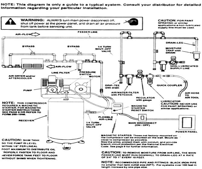
16 Installation Diagram
17 Start Up Preparation & Procedures The following check list shall be adhered to before putting the compressor into operation. FAILURE TO PERFORM THE CHECKS MAY RESULT IN SERIOUS INJURY OR DEATH, PROPERTY DAMAGE AND/OR MECHANICAL FAILURE. DISCONNECT AND LOCK OUT POWER SUPPLY. 1. Remove all loose pieces and tools around the compressor installation. 2. Check oil level in crankcase, add as necessary. 3. Check all pressure connections for tightness and leaks. 4. Check to make sure all safety relief valves are in place and operational. 5. Check to be sure all guards are in place and securely mounted. 6. Check fuses, circuit breakers and thermal overloads for proper size. 7. Open all manual shut-off valves (block valves) at and beyond the compressor discharge. 8. On all 3 phase units, after all of the above conditions have been satisfied, jog the starter switch button to check the rotational direction of the compressor. It should agree with the rotation arrow on the flywheel/pulley (counter clockwise, facing the shaft). The following procedures should be followed for start-up of a new installation, or after changes have been made to an existing installation, and/or after service repair work has been performed. 1. Instructions in addition to those contained within this manual, supplied by manufacturers of supporting equipment, must also be read and understood before start-up. 2. Check oil level in crankcase. 3. Drain moisture from air receiver and traps. 4. Start compressor and watch for excessive vibration or strange noises. If either is observed, stop the compressor immediately and correct. 5. Check air receiver or system pressure. 6. Manually activated safety relief valves by pulling ring or lever. 7. Check operation of controls. 8. After two days of operation check belt tension, air piping for leaks, and crankcase oil level.
18 Stopping for Maintenance or Service! Never assume the compressor is ready for maintenance or service because it is stopped. The automatic stop-start control may start the compressor at any time! CAUTION THE FOLLOWING PROCEDURE SHOULD BE FOLLOWED TO MAXIMIZE SAFETY WHEN PREPARING FOR MAINTENANCE OR SERVICE. 1. Disconnect and lock-out the main power switch and hang a sign at the switch Informing of the unit being serviced. 2. Close shut-off valve (block valve) between receiver and compressor, or receiver and Plant air system, to prevent any back-up of air flow into the area to be serviced. 3. Lock open manual vent valve and wait for the pressure in the area to be serviced (compressor, receiver, etc.) to be completely relieved before starting service. The Manual vent valve may be the drain valve in the receiver. NEVER remove a plug to relieve the pressure. 4. Open all manual drain valves within the area to be serviced. 5. Wait for the unit to cool before starting service, (temperatures at 125 degrees F can burn the skin), some surface temperatures exceed 400 degrees F when the compressor is working). 6. Clean up all oils spills immediately to prevent slipping. (Mark spill area accordingly.) Common Maintenance Parts CA1(U) PUMP Reciprocating Pump Oil Air Filter Element Air Filter Housing CA2(U) PUMP Reciprocating Pump Oil Air Filter Element Air Filter Housing Part Number IAT IAT-CA IAT-CA Part Number IAT IAT-CA IAT-CA PUMP OIL CAPACITIES Ounces CA1(U) 50 CA2(U) 60 G LDV95T 30 LDV80 30 LDV65 22 LDV51 22 G43 PUMP Reciprocating Pump Oil Air Filter Element Air Filter Housing Part Number IAT IAT-CA IAT-CA Part numbers subject to change/update always consult factory prior to ordering
19 Maintenance Procedures Review DAILY: Drain the Receiver- condensation will accumulate in the tank daily, and should be drained at least once a day. This is done to reduce corrosions of the tank from the inside. Always wear protective eye wear when draining the tank. Check Pump Oil Level- All units have a sight glass the oil level non running units should be no lower than ½ way on the sight glass if it is lower then you need to add oil until it is at least ½ way up the sight glass. Check unit for any unusual noise or vibrations. WEEKLY: Clean air filter: this will ensure that no dirt or heavy particulate makes its way into the compressors valve assemblies. Clean external parts of compressor and electric motor: this helps to ensure proper cooling and prevents rust and corrosion on critical parts. Check safety Valves: this is don t to ensure they are not stuck in place and operating properly. Elite Units Check auto tank drain for proper function MONTHLY: Inspect complete air system for leaks: this is done to make sure the compressor does not get out of its duty cycle due to air leak in the system. Inspect Oil for Contamination: this is done to ensure that harmful deposits do not build up in the oil. Check belt tension: this is done to ensure the belt do not fail pre-maturely, tighten them as needed to ensure they do not slip. If belts are loose, tighten per instructions on next page. Failure to tighten can cause pre-mature belt failure. EVERY 3 MONTHS OR 500HRS (WHICHEVER COMES FIRST): Change Oil: this is done to ensure that the compressor has proper oil level and that the oil in the machine does not deteriorate past factory specifications. Inspect Valve assemblies: this is done to prevent premature failure and clean out and carbon that can form in older valves. *ELITE UNITS: Clean auto tank drain strainer and check for proper function. Inspect pressure switch for proper function. Inspect check valve for proper function and remove any carbon accumulation to prevent premature failure. *Clean belt guard coolers (if equipped). STORAGE OF COMPRESSOR: Before storing the compressor for a prolonged period of time, use a blow gun to clean all debris from compressor. Shut OFF main power and turn OFF disconnect. Drain tank pressure, clean air filter, drain old oil and replace with new oil. Cover the unit to prevent dust and moisture from collecting on the unit. NOTE: Maintaining proper oil level and performing oil changes at proper intervals is necessary for the proper function of the air compressor system. The best oil for you air compressor is CAS30100 full synthetic reciprocating compressor oil. Your average vehicle travels 30,000 highway miles in 500 hrs or 15,000 city miles in 500 hrs at 210 º F or less. In the same 500 hrs/3 months a reciprocating compressors operating temperature may exceed 350 º F.
20 Certificate of Limited Warranty Reciprocating Compressors All component parts on this compressor installed by the manufacturer are warranted to be free of defects, workmanship and material for a period of one year. Transportation charges are the responsibility of the purchaser. This warranty extends to the original purchaser of the compressor only. The purchaser must use Compressed Air Systems synthetic reciprocating compressor oil in the compressor for the duration of the compressor warranty. There are NO express warranties except other than those contained in this limited warranty statement. Covered in the one year period of the warranty are defective parts due to defects in the original part only. The compressor warranty is void in the case of abuse, lack of proper service, in correct application, in correct installation, and neglect. Standard compressor warranty covers defective parts and labor for the one year period. Industrial electric stationary compressors may be repaired on site as long as the compressor is not located further than 50 miles from the service center. The purchaser is responsible for any additional travel expense past 50 miles from the service center. Gas/Diesel engine driven, Single stage stationary, and Contractor series compressors must be repaired at the closest service center to the compressor. The purchaser is responsible for any travel expense if they do not wish to bring the compressor to the service center. ALL SPECIALTY COMPRESSOR WARRANTY SERVICE MUST BE PERFORMED AT THE CLOSEST SERVICE CENTER TO THE COMPRESSOR. Specialty compressor - any compressor package with options other than those that apply to the standard model number in the catalog. ALWAYS CONTACT MANUFACTURER TECH SUPPORT FOR FASTEST SOLUTION BEFORE WARRANTY SERVICE IS PERFORMED. WARRANTY LABOR FOR THE FIRST YEAR IS ONLY COVERED FOR WORK PERFORMED MONDAY-FRIDAY 8AM-5PM EXCLUDING ALL MAJOR US HOLIDAYS. OPTIONAL 6 YEAR INDUSTRIAL RECIPROCATING PUMP ONLY WARRANTY To be applicable for this option purchaser must purchase the Full Year reciprocating compressor maintenance kit at the same time as the compressor. A subsequent kit must be purchased every 12 months from the date of the original purchase for a total of 6 kits during the warranty of the period of the pump. The purchaser must use only Compressed Air Systems synthetic reciprocating compressor oil in the compressor for the duration of the compressor warranty. The warranty covers the Industrial reciprocating pump for a period of 6 years parts replacement only for any part with a defect from the manufacturer, excluding the compressor valves which carry the same 1 year standard warranty. The warranty does not cover standard wear and tear on parts, abuse, neglect, improper service, misapplication, and improper installation. The purchaser is responsible for any freight/shipping expense incurred. Important Always contact manufacturer tech support for fastest solution before warranty service is performed. Before warranty service can be performed on a unit the servicing company must contact the manufacture to get a warranty procedure verification number. Without a warranty verification number work may not be covered by the manufacturer under warranty. A warranty verification number does not guarantee a part or piece of the product is warrantable but guarantees it will be reviewed for warranty credit. All warranty replacement parts must be Compressed Air Systems OEM part unless authorization is given from Compressed Air Systems factory representative
21 NEC (National Electric Code) Guide Lines 1 Phase Motor Requirements (Copper wire must be THW, THHN-THWN, XHHW) No solid core wire NOTE: Wire size is based on being within 30ft of main electrical panel installation further would need a qualified electrician to properly size the wire to account for voltage drop Horse Power Voltage Instantaneous Trip Circuit Breaker Rating Circuit Breaker Trip Rating Minimum Wire Size NOTE: Some rotary screw compressors have additional drive motors for the coolings fans these need to be taken into account when sizing the electrical system 3 Phase Motor Requirements (Copper wire must be THW, THHN-THWN, XHHW) No solid core wire NOTE: Wire size is based on being within 30ft of main electrical panel installation further would need a qualified electrician to properly size the wire to account for voltage drop Horse Power Voltage Circuit Breaker Trip Rating Minimum Wire Size Horse Power Voltage Circuit Breaker Trip Rating /O /O /O /O /O /O Minimum Wire Size NOTE: Some rotary screw compressors have additional drive motors for the coolings fans these need to be taken into account when sizing the electrical system
22 Reciprocating Compressor Installation Sheet Date of Installation Installation Company Installation Technician Site Electrical Phase Compressor Model# Compressor Serial # Compressor Voltage Site Voltage L1 L2 L3 Compressor Electrical breaker size Incoming Voltage at motor start up L1 L2 L3 Incoming Voltage at max operating pressure L1 L2 L3 Incoming power connected to Magnetic Starter Breaker size for the compressor AMPS Distance from main electric panel Wire size for the compressor Disconnect installed at the compressors site If Duplex compressor separate disconnects for each drive motor: N Yes N No Compressor Rotation Correct N Yes N No Motor amps at max operating Pressure L1 L2 L3 Compressor Max Operating Pressure Unit inspected for Air leaks Compressor tank drain functional Unit inspected for Oil leaks Unit location: N Indoors N Outdoors Unit tank fill time 0-125psi Unit tank fill time 0-150psi Unit tank fill time 0-175psi (Put N/A if pressure not applicable to installed unit) (Put N/A if pressure not applicable to installed unit) (Put N/A if pressure not applicable to installed unit) Belt tension checked: N Yes N No _ Vibration Pads properly installed: N Yes N No All installation steps completed: N Yes N No If no, reason: Send copy of completed installation sheet to manufacture to begin warranty Compressed Air Systems, LLC 2626 Skyway Drive Grand Prairie, TX, 75052
23 WARNING: Always wear proper protective eye ware, hearing protection and safety clothing when working around the compressor package. No loose or baggy clothing should be worn around compressor package at any time. WARNING: On Electric motor powered air compressors make sure electrical system is up to National Electric Code (NEC) prior to installing compressor system. Failure to install a compressor with a proper NEC electrical system can cause personal injury, compressor package damage and void compressor package warranty NOTICE: To ensure full compressor tank warranty all tank mounted compressor packages must be mounted on factory approved vibration isolation pads. A compressor should NEVER be installed while still on or in its original packaging. Failure to properly install the compressor system with approved vibration isolation pads will result in the compressor tank warranty being void. WARNING: Compressed Air Systems compressors can operate at pressures from 0-250psi depending on the compressor package design and build specifications. Always verify that the system the compressor is installed into can handle the maximum operational pressure the compressor. NEVER install a compressor in a system that can not handle the compressors maximum operating pressure. WARNING: Compressed air is extremely dangerous when not properly used or installed. Always make sure a trained compressed air professional has looked over the air system prior to use. Improper installation or use of compressed air can cause bodily injury or death. NEVER pressurize an object that was not designed to be pressurized. Pressurizing objects not properly engineered for the maximum operating pressure of the compressor system can cause bodily injury or death. Additional Information For compressor pump information see pump specific manual. For installation instructions see Install Guide. For compressor package wiring diagram contact manufacturer. For compressor parts breakdown see website (compressed-air-systems.com) of contact compressor manufacturer. On electric driven compressors always follow NEC (National Electric Code) on any local applicable code that exceeds NEC guidelines. On gas/diesel engine driven packages follow engine manufacturer guide for proper placement and installation of engine driven equipment.
24 Compressed Air Systems, LLC 2626 Skyway Drive Grand Prairie, TX, Fax Simplicity. It s What We Do. Compressed Air Systems, LLC
Oil Free Reciprocating Compressors
 Oil Free Reciprocating Compressors Owners Manual Introduction. Congratulations on the purchase of your new air compressor. The air compressor is precision built from the finest materials using the finest
7.5 HP Electric Duplex Reciprocating Compressor
 7.5 HP Electric Duplex Reciprocating Compressor Owners Manual Introduction. Congratulations on the purchase of your new air compressor. The air compressor is precision built from the finest materials using
Commercial Duty Compressors
 Commercial Duty Compressors Owners Manual Introduction. Congratulations on the purchase of your new air compressor. The air compressor is precision built from the finest materials using the finest state
HP Gas/Diesel Engine Reciprocating Compressors
 8.5-15 HP Gas/Diesel Engine Reciprocating Compressors Owners Manual Introduction. Congratulations on the purchase of your new air compressor. The air compressor is precision built from the finest materials
Gas/Diesel Engine Compressor/Generator Compressor/Generator/Welder
 Gas/Diesel Engine Compressor/Generator Compressor/Generator/Welder Owners Manual Introduction. Congratulations on the purchase of your new air compressor. The air compressor is precision built from the
120 GALLON HORIZONTAL AIR COMPRESSOR
 120 GALLON HORIZONTAL AIR COMPRESSOR User Manual BEPOWEREQUIPMENT.COM 2 table of contents Introduction 5 Using the Operator s Manual Product Identification 6 Record Identification Numbers Safety 7 Safety
Electric Reciprocating Compressor. Installation Guide
 Electric Reciprocating Compressor Installation Guide Air compressors should only be installed trained installation personnel call 800-531-9656 to find a local trained. Warning: Read all installation steps,
vertrical air compressor
 vertrical air compressor AC5080B AC7580B user manual BEPOWEREQUIPMENT.COM table of contents table of contents Introduction 4 Using the Operator s Manual Product Identification 5 Record Identification Numbers
Enclosed Electric Rotary Screw Compressor Installation Guide
 Enclosed Electric Rotary Screw Compressor Installation Guide Air compressors should only be installed trained installation personnel call 800-531-9656 to find a local trained. Warning: Read all installation
Hydraulic Driven Reciprocating & Rotary Screw Compressors
 Hydraulic Driven Reciprocating & Rotary Screw Compressors Owners Manual Introduction Congratulations on the purchase of your new air compressor. The air compressor is precision built from the finest materials
Hydraulic Driven Reciprocating & Rotary Screw Compressors
 Hydraulic Driven Reciprocating & Rotary Screw Compressors Owners Manual Introduction Congratulations on the purchase of your new air compressor. The air compressor is precision built from the finest materials
Rotary Screw Compressors Gas & Diesel Driven
 Rotary Screw Compressors Gas & Diesel Driven Owners Manual Introduction. Congratulations on the purchase of your new air compressor. The air compressor is precision built from the finest materials using
FAILURE TO COMPLY WITH INSTRUCTIONS IN THIS MANUAL COULD RESULT IN THE VOIDING OF YOUR WARRANTY, AND PERSONAL INJURY, AND/OR PROPERTY DAMAGE
 Gas & Diesel Rotary Screw Compressor/Generator Compressor/Generator/Welder Owners Manual Introduction Congratulations on the purchase of your new air compressor. The air compressor is precision built from
Open Frame Gas/Diesel Engine Driven Rotary Screw Compressor. Installation Guide
 Open Frame Gas/Diesel Engine Driven Rotary Screw Compressor Installation Guide Air compressors should only be installed trained installation personnel call 800-531-9656 to find a local trained. Warning:
Open Frame Reciprocating Gas/Diesel Engine Driven Compressor. Installation Guide
 Open Frame Reciprocating Gas/Diesel Engine Driven Compressor Installation Guide call 800-531-9656 to find a local trained air compressor service technician. Warning: Read all installation steps, compressor
Owners Manual. Compressor Generator Combination Packages HP Generator Packages kw. Compressed Air Systems
 Compressor Generator Combination Packages 35-105 HP Generator Packages 15-90 kw Owners Manual Always check www.compressed-air-systems.com for current manual and compressor service or technical information
Compressor Manual HP Diesel Engine Drive Reciprocating Compressor
 Compressor Manual 16.8 HP Diesel Engine Drive Reciprocating Compressor INTRODUCTION Congratulations on the purchase of your new air compressor. The air compressor is precision built from the finest materials
HP Electric Rotary Screw Compressors
 75-100 HP Electric Rotary Screw Compressors Owners Manual Introduction. Congratulations on the purchase of your new air compressor. The air compressor is precision built from the finest materials using
AIR COMPRESSOR OPERATING INSTRUCTION AND PARTS LIST
 AIR COMPRESSOR OPERATING INSTRUCTION AND PARTS LIST BELT TYPE IMPORTANT PLEASE MAKE CERTAIN THAT THE PERSON WHO IS TO USE THIS EQUIPMENT CAREFULLY READS AND UNDERSTANDS THESE INSTRUCTIONS BEFORE STARTING
C T h e A d va n t a g e
 C The Advantage TABLE OF CONTENTS Introduction...1 Product Numbering System...1 Safety...2 Receiving and Inspection...2 Installation...2 Electrical...3 Parts Identification...7 Lubrication...9 Start-up...10
AIR COMPRESSOR AC5161B AC5161BP. User Manual
 AIR COMPRESSOR AC5161B AC5161BP User Manual table of contents table of contents Safety 6 Safety Rules 7 Safety Warnings Overview 11 Basic Air Compressor Components Assembly 13 Assembling the Compressor
Portable Electric/Gas Compressor Operating Instructions
 Portable Electric/Gas Compressor Operating Instructions NOTICE Carefully read this instruction manual before attempting to operate this compressor. MODEL # SERIAL # 1-800-551-2406 TABLE OF CONTENTS Safety
PRODUCT NUMBERING SYSTEM SERIES PHASE. HD: Heavy Duty (15,000+ hour life) SD: Standard Duty (5,000+ hour life) LD: Light Duty (2,000+ hour life)
 SD: Standard Duty (5,000+ hour life) LD: Light Duty (2,000+ hour life)") TABLE OF CONTENTS Product Numbering System...1 Safety...2 Receiving and Inspection...2 Installation...2 Electrical...3 Parts Identification...7 Lubrication...9 INTRODUCTION The compressor you have purchased
TABLE OF CONTENTS Product Numbering System...1 Safety...2 Receiving and Inspection...2 Installation...2 Electrical...3 Parts Identification...7 Lubrication...9 INTRODUCTION The compressor you have purchased
INSTRUCTION MANUAL: Industrial Series Piston Air Compressor. Model Number: V Part Number: L001128KNA
 INSTRUCTION MANUAL: Industrial Series Piston Air Compressor Model Number: V8051-335 Part Number: L001128KNA Pump Model: LP335 K335 Motor: 5 HP / 1 PH Air Tank: 80 Gal Vertical 1830 W. 15 th St. Houston,
PRODUCT NUMBERING SYSTEM SERIES PHASE. 1: Single Phase 3: Three Phase
 TABLE OF CONTENTS Product Numbering System and Specifications... Safety... Receiving and Inspection... Installation... Electrical...6 Start-up...7 INTRODUCTION The compressor you have purchased is a combination
Portable Oil Free Silent Series Compressor Operating Instructions
 Portable Oil Free Silent Series Compressor Operating Instructions NOTICE Carefully read this instruction manual before attempting to operate this compressor. MODEL # SERIAL # 1-800-551-2406 www.eaglecompressor.com
SPECIFICATIONS: Tank Size: 80 gallons PUMP RPMs: 1050 CFM: 40PSI; 90 PSI Max Pressure: 150 PSI Thermal overload protection
 5HP 80 GALLON TWO STAGE COMPRESSOR Models: 51866, 51870 CALIFORNIA PROPOSITION 65 WARNING: You can create dust when you cut, sand, drill or grind materials such as wood, paint, metal, concrete, cement,
Installation and Operating Manual
 Installation and Operating Manual OIL-LESS RECIPROCATING AIR COMPRESSOR CIL Series INSTALLATION & OPERATING MANUAL OIL-LESS RECIPROCATING AIR COMPRESSOR TABLE OF CONTENTS Page 1 DESCRIPTIONS A. GENERAL
SPECIFICATIONS Horsepower: 1.5 HP Running Maximum PSI: 125 PSI Tank Capacity: 15 Gallons CFM: 6 40 PSI 5 90 PSI
 15 GALLON AIR COMPRESSOR Model: 7678 DO NOT RETURN TO STORE Please call 800-348-5004 for parts and service CALIFORNIA PROPOSITION 65 WARNING: You can create dust when you cut, sand, drill or grind materials
Installation and Service Manual for SRC25, SRC252, SRC50, SRC502, SRC75, SRC752
 Rocking Piston Compressors Installation and Service Manual for SRC25, SRC252, SRC50, SRC502, SRC75, SRC752 Thank you for purchasing the Stratus SRC series rocking piston compressor. This instruction manual
READ AND SAVE THESE INSTRUCTIONS. Centrifugal Downblast Exhaust Fan Belt Driven for Roof & Wall Mounting
 READ AND SAVE THESE INSTRUCTIONS INSTALLATION, OPERATING INSTRUCTIONS & PARTS MANUAL Centrifugal Downblast Exhaust Fan Belt Driven for Roof & Wall Mounting Electrical wiring and connections should be done
READ AND SAVE THESE INSTRUCTIONS. High Velocity Restaurant-Duty Utility Set Belt Driven for Roof Mounting
 READ AND SAVE THESE INSTRUCTIONS INSTALLATION, OPERATING INSTRUCTIONS & PARTS MANUAL High Velocity Restaurant-Duty Utility Set Belt Driven for Roof Mounting Electrical wiring and connections should be
M-3025CB-AV Fuel Pump
 SAVE THESE INSTRUCTIONS M-3025CB-AV Fuel Pump Owner s Manual TABLE OF CONTENTS General Information... 2 Safety Instructions... 2 Installation... 3 Operation... 4 Maintenance... 4 Repair... 5 Troubleshooting...
Iron Horse Air Compressor part breakdown - IHD6160V1 Item Description IHD6160V1 IHD6160V1 Call for the Customer Service Department.
 Iron Horse Air Compressor part breakdown - IHD6160V1 Item Description IHD6160V1 1 Compressor w/ Flywheel CC2065 2 Discharge Tube w/ Fittings TU-23-AL 3 Pressure Gauge PG200-2.5R 4 Air Receiver 60V20X48SPL
Operating Instructions - Electric Pow'r-Riser Models
 ADivisionOf Templeton, Kenly& Co., Inc. Operating Instructions - Electric Pow'r-Riser Models Table of Contents 1.0 Recieving Instructions 2.0 Safety 3.0 Specifications 4.0 Initial Installation Before Operating
UNPACKING SAFETY GUIDELINES GENERAL SAFETY INFORMATION. Operating Instructions & Maintenance Manual
 Please read and save this Repair Parts Manual. Read this manual and the General Operating Instructions carefully before attempting to assemble, install, operate or maintain the product described. Protect
Pump Owner s Manual. PLEASE! Read All Instructions Carefully Before Installing Pump
 Pump Owner s Manual PLEASE! Read All Instructions Carefully Before Installing Pump Guarantee Associate Engineering Corporation warrants that pumps purchased from them will be free of defects in material
Routine Compressor Maintenance
 Establishing a regular, well-organized maintenance program and strictly following it is critical to maintaining the performance of a compressed air system. One person should be given the responsibility
H.S. MACHINERY RING COMPRESSORS
 OPERATION & PARTS MANUAL Thank you for purchasing an H.S Machinery Limited Regenerative Blower. This product is manufactured under strict ISO-9001-2000 quality control guidelines to ensure your satisfaction.
DISCLAIMER: SPECIFICATIONS:
 5HP 80 GALLON TWO STAGE COMPRESSOR Models: 7654 CALIFORNIA PROPOSITION 65 WARNING: You can create dust when you cut, sand, drill or grind materials such as wood, paint, metal, concrete, cement, or other
UNPACKING SAFETY GUIDELINES GENERAL SAFETY INFORMATION. Operating Instructions & Maintenance Manual
 Please read and save this Repair Parts Manual. Read this manual and the General Operating Instructions carefully before attempting to assemble, install, operate or maintain the product described. Protect
Hydraulic Immediate Need Power Pack
 Safety, Operation, and Maintenance Manual WARNING Improper use of this tool can result in serious bodily injury This manual contains important information about product function and safety. Please read
6L Oil-less Air Compressor 53103
 6L Oil-less Air Compressor 53103 Operating Instructions Please read and save these instructions before attempting to assemble, install, operate or maintain the product. Protect yourself and others by observing
Installation and Service Manual for RV33, RV332, RV75, RV752, RV100, RV1002
 Rotary Vane Compressors RV Series Installation and Service Manual for RV33, RV332, RV75, RV752, RV100, RV1002 Thank you for purchasing the Stratus RV series rotary vane compressor. This instruction manual
1. GENERAL INFORMATION WARRANTY- PARTS - SERVICE SERIAL # ITEM # Printed in Canada Issue Date: October 2010 Revision 12
 TABLE OF CONTENTS SECTION PAGE 1 GENERAL INFORMATION 2 2 SAFETY GUIDELINES 3 3 OPERATION 4 3.1 How the Compressor Works 4 3.1.1 Components 4 3.1.2 Controls 5 3.1.3 Inlet Air System 6 3.1.4 Discharge System
INSTALLATION, OPERATION AND MAINTENANCE MANUAL WALL EXHAUST FANS BELT DRIVE XBL FANS
 INSTALLATION, OPERATION AND MAINTENANCE MANUAL WALL EXHAUST FANS BELT DRIVE XBL FANS The purpose of this manual is to aid in the proper installation and operation of the fans. These instructions are intended
BOILER FEED SYSTEM OPERATION AND MAINTENANCE MANUAL
 BOILER FEED SYSTEM OPERATION AND MAINTENANCE MANUAL IMPORTANT These instructions are intended as a guide for the Installing Contractor and as a reference for the Operator, Owner and Serviceman. RETAIN
ELECTRIC MOTOR. Owner s Manual
 ELECTRIC MOTOR Owner s Manual WARNING: Read carefully and understand all ASSEMBLY AND OPERATION INSTRUCTIONS before operating. Failure to follow the safety rules and other basic safety precautions may
SPLASH LUBRICATED AIR COMPRESSOR PUMPS
 Operating Instructions SPLASH LUBRICATED AIR COMPRESSOR PUMPS Airbase Industries designs and manufactures products for safe operation. However, operators and maintenance persons are responsibile for maintaining
READ AND SAVE THESE INSTRUCTIONS. Centrifugal Upblast Exhaust Fan (Standard & High Pressure Exhaust) Belt Driven for Roof & Wall Mounting
 Belt Driven for Roof & Wall Mounting") READ AND SAVE THESE INSTRUCTIONS INSTALLATION, OPERATING INSTRUCTIONS & PARTS MANUAL Centrifugal Upblast Exhaust Fan (Standard & High Pressure Exhaust) Belt Driven for Roof & Wall Mounting Electrical wiring
READ AND SAVE THESE INSTRUCTIONS INSTALLATION, OPERATING INSTRUCTIONS & PARTS MANUAL Centrifugal Upblast Exhaust Fan (Standard & High Pressure Exhaust) Belt Driven for Roof & Wall Mounting Electrical wiring
Electric Motor. Owner s Manual
 Electric Motor Owner s Manual WARNING: Read carefully and understand all ASSEMBLY AND OPERATION INSTRUCTIONS before operating. Failure to follow the safety rules and other basic safety precautions may
INSTALLATION, OPERATION AND MAINTENANCE MANUAL WALL EXHAUST FANS BELT & DIRECT DRIVE XB, HV, HVA, ADD, DDS, DDP
 INSTALLATION, OPERATION AND MAINTENANCE MANUAL WALL EXHAUST FANS BELT & DIRECT DRIVE XB, HV, HVA, ADD, DDS, DDP The purpose of this manual is to aid in the proper installation and operation of the fans.
SIP Direct Drive Oil-Lube Air Compressors - Operating & Maintenance Instructions
 SIP Direct Drive Oil-Lube Air Compressors - Operating & Maintenance Instructions Please read and fully understand the instructions in this manual before operation. Keep this manual safe for future reference.
Model &
 PumpAgents.com - Click here for Pricing/Ordering Model 31765-0092 & 31765-0094 Dual Sensor Max VSD WATER PRESSURE SYSTEM AUTOMATIC TWO STAGE WATER SYSTEM WITH PUMPGARD STRAINERS IDEAL FOR PLEASURE AND
TC Series Cooling Systems
 TC Series Cooling Systems Table of Contents Table of Contents...1 List of Figures...1 Safety...2 Introduction...2 General Specifications...2 Types of Coolant...2 Routine Maintenance...2 Surge Tank Coolant
Electrical... 5 Start-up... 6 Digital Pressure Switch Programming and Instructions... 7 Maintenance... 8 PRODUCT NUMBERING SYSTEM PHASE SERIES
 TABLE OF CONTENTS Product Numbering System and Specifications... Safety... Receiving and Inspection... Installation... Electrical... 5 Start-up... 6 Digital Pressure Switch Programming and Instructions...
Installation Operation & Maintenance Manual. Oil-Free (Dry) Rotary Vane Vacuum Pump Systems
 Rotary Vane Vacuum Pump Systems") Installation Operation & Maintenance Manual Oil-Free (Dry) Rotary Vane Vacuum Pump Systems Part No. 9983-0000-S07 / November 2018 OIL-FREE (DRY) ROTARY VANE VACUUM PUMP SYSTEMS TABLE OF CONTENTS CUSTOMER
Installation Operation & Maintenance Manual Oil-Free (Dry) Rotary Vane Vacuum Pump Systems Part No. 9983-0000-S07 / November 2018 OIL-FREE (DRY) ROTARY VANE VACUUM PUMP SYSTEMS TABLE OF CONTENTS CUSTOMER
Operating instructions Form no safety definitions
 Operating instructions Form no. 1000437 safety definitions safety symbols are used to identify any action or lack of action that can cause personal injury. Your reading and understanding of these safety
QUALITY MISTING PUMPS
 TOTALLY ENCLOSED DIRECT DRIVE 60030KH, 60031KH, 60050KH, 60051KH 60100KH, 60101KH, 60150KH, 60151KH MISTING PUMP MANUAL INCLUDING: SPECIFICATION DATA, GENERAL SAFETY PRECAUTIONS, OPERATION, INSTALLATION,
OPERATING SERVICE MAINTENANCE MANUAL
 OPERATING SERVICE MAINTENANCE MANUAL ALL-STAR ROCKING PISTON COMPRESSOR AND VACUUM PUMP Registered by one or more of these standards agency ISO RoHS 9001 Compliant CE Read through carefully and understand
INSTALLATION OPERATING MAINTENANCE INSTRUCTIONS
 INSTALLATION OPERATING MAINTENANCE INSTRUCTIONS ROTARY VANE -00% OIL-FREE VACUUM PUMP OR COMPRESSOR 0 to 08 0 to 0 3060 to 3080 C CE RoHS ISO 9000:00 300 to 30 Read through carefully and understand these
OWNER S MANUAL SELF-PRIMING PORTABLE UTILITY PUMP
 Model 54011-0 OWNER S MANUAL SELF-PRIMING PORTABLE UTILITY PUMP Questions, problems, missing parts? Before returning to the store call AQUAPRO Customer Service 8 a.m. - 5 p.m., EST, Monday-Friday 1-844-242-2475
QUALITY MISTING PUMPS
 DIRECT DRIVE TOTALLY ENCLOSED FAN COOLED 60200KH, 60201KH MISTING PUMP MANUAL INCLUDING: SPECIFICATION DATA, GENERAL SAFETY PRECAUTIONS, OPERATION, INSTALLATION, PARTS, MAINTENANCE & WARRANTY QUALITY MISTING
Matala. VersiFlow Series. Instruction and Maintenance Manual
 VersiFlow Series High Flow Multi-Purpose "Versatile " Pump V-3200 1/5HP 150W / Discharge 2 V-3900 1/3HP 250W / Discharge 2 V-4700 1/2HP 400W / Discharge 2 V-5600 1HP 750W / Discharge 2 Instruction and
Hydraulic PTO Flow Device
 Safety, Operation, and Maintenance Manual WARNING Improper use of this tool can result in serious bodily injury This manual contains important information about product function and safety. Please read
PE 20 SERIES ELECTRIC POWER PUMPS
 A Division Of Templeton, Kenly & Co., Inc. PE 20 SERIES ELECTRIC POWER PUMPS Operating Instructions Manual For 1/2 hp, 115 Volt and 230 Volt PEM, PPM, PES and PPS Models Revison B 07/2006 2525 Gardner
IMPORTANT SAFETY INSTRUCTIONS
 Table of Contents Safety... 2 Specifications... 3 Functions... 4 Operation... 5 Maintenance... 7 Warranty... 7 SAFETY SPECIFICATIONS OPERATION MAINTENANCE WARNING SYMBOLS AND DEFINITIONS This is the safety
AUTOMATIC SUBMERSIBLE UTILITY PUMP
 AUTOMATIC SUBMERSIBLE UTILITY PUMP Zoeller is a registered trademark of Zoeller Co. All Rights Reserved. MODEL #1043-0006 Español p. 9 ATTACH YOUR RECEIPT HERE Serial Number Purchase Date Questions, problems,
Jet Fans. Instruction Manual READ AND SAVE THESE INSTRUCTIONS WARRANTY
 Jet Fans Instruction Manual READ AND SAVE THESE INSTRUCTIONS WARRANTY All Leader Fan products are guaranteed to be free from defects of workmanship or material and to function satisfactorily when properly
Air Curtain. Installation, Operating and Maintenance Instructions
 Installation, Operating and Maintenance Instructions Save this manual for future reference. Air Curtain Model Numbers: ES026, ES036, ES042, ES048, ES060, ES072 READ THIS OWNER S MANUAL CAREFULLY BEFORE
DIRECT-DRIVE PRESSURE WASHERS
 DIRECT-DRIVE PRESSURE WASHERS PJG SERIES PRESSURE WASHER MANUFACTURED BY: PJG-2002B PJG-2502-6.5B PJG-3002B PJG-4002B INTRODUCTION Thank you for purchasing a Mancorp Pressure Washer. This manual covers
TITAN FLOW CONTROL, INC.
 PREFACE: This manual contains information concerning the installation, operation, and maintenance of Titan Flow Control (Titan FCI) Wafer Style, Dual Plate Check Valves. To ensure efficient and safe operation
ESE Series Cast Iron Sewage Pumps
 Owner s Manual ESE Series Cast Iron Sewage Pumps TABLE OF CONTENTS General Safety.................... 2 Specifications..................... 3 Installation.................... 4 & 5 Troubleshooting...................
AC3020B AC3030B PORTABLE AIR
 AC3020B AC3030B PORTABLE AIR operation manual CAUTION READ THIS MANUAL CAREFULLY before operating or servicing this air compressor, to familiarize yourself with the proper safety, operation, and standard
 Operation and Maintenance Manual http://www.torsionx.eu Use the MaxDrv Series Square Drive Torque Wrench Model.75, 1, 3, 5, 8, 10, 20, 25, 35, 50 to install and remove threaded fasteners requiring precise
See Warranty on page 6 for important information about commercial use of this product.
 See Warranty on page 6 for important information about commercial use of this product. Operating Instructions WL6000 Series Please read and save these instructions. Read carefully before attempting to
UNPACKING SAFETY GUIDELINES GENERAL SAFETY INFORMATION. Operating Instructions & Maintenance Manual
 Please read and save this Repair Parts Manual. Read this manual and the General Operating Instructions carefully before attempting to assemble, install, operate or maintain the product described. Protect
PEDESTAL SUMP PUMP. MODEL # Español p. 11. Zoeller is a registered trademark of Zoeller Co. All Rights Reserved.
 PEDESTAL SUMP PUMP Zoeller is a registered trademark of Zoeller Co. All Rights Reserved. MODEL #1084-0001 Español p. 11 ATTACH YOUR RECEIPT HERE Serial Number Purchase Date Questions, problems, missing
Model and Series 115 VAC INDUSTRIAL DIAPHRAGM PUMPS. PumpAgents.com - buy pumps and parts online INDUSTRIAL DIAPHRAGM PUMPS
 Model 31801 and 31800 Series 115 VAC INDUSTRIAL DIAPHRAGM PUMPS INDUSTRIAL DIAPHRAGM PUMPS FEATURES Run Dry Ability Self-Priming Thermal Overload Protected Motor Easy Installation Low Amp Draw Compact
750 Series Press Conveyor Installation and Maintenance Manual
 750 Series Press Conveyor Installation and Maintenance Manual Metzgar Conveyor Co. - 2010 METZGAR CONVEYORS SAFETY PRECAUTIONS WARNING: DO NOT ATTEMPT MAINTENANCE ON ANY CONVEYORS WHILE IN OPERATION. BEFORE
QSSE, QSSEX INDUSTRIAL Battery Chargers
 C O R P O R A T IO N O P E R A T I N G I N S T R U C T I O N S QSSE, QSSEX INDUSTRIAL Battery Chargers INTRODUCTION The QSE line are electronically controlled float chargers. The batteries are brought
IMPORTANT! READ BEFORE PROCEEDING! PHR Axial Flow Hooded Roof Ventilators
 PHR Axial Flow Hooded Roof Ventilators OPERATION & MAINTENANCE Revised: 08/24/15 IMPORTANT! READ BEFORE PROCEEDING! The information contained herein is, to the best of our knowledge, accurate and applicable
OBE, OBEXU, ON BOARD Battery Chargers
 C O R P O R A T IO N O P E R A T I N G I N S T R U C T I O N S OBE, OBEXU, ON BOARD Battery Chargers INTRODUCTION: These chargers are designed for the permanent installation on battery powered vehicles
ProFlo FatBoy
 The Standard For Professional Grade Diaphragm Pumps. ProFlo 3300 5500 FatBoy Operational and Installation Guidelines, Repair & Parts Contents 3300 5500 Fatboy Operational and Installation Guidelines...2
SLR / SLR-S/N. Instruction Manual. Walrus America Inc
 SLR / SLR-S/N Instruction Manual Walrus America Inc 1. Installation and Connection 1.1. Pump Installation The pump should be sited in a well ventilated and frost-free position. The distance between pumps-motors
OBAE, OBAEXU, ON BOARD Battery Chargers
 C O R P O R A T IO N O P E R A T I N G I N S T R U C T I O N S OBAE, OBAEXU, ON BOARD Battery Chargers INTRODUCTION: The OBAE line of chargers are designed for the permanent installation on battery powered
MMA 160S ARC/MMA WELDER OPERATION INSTRUCTIONS
 www.r-techwelding.co.uk MMA 160S ARC/MMA WELDER OPERATION INSTRUCTIONS 2 Thank you for selecting the R-Tech MMA160S Inverter Arc Welder. The MMA160S has many benefits over traditional Arc welders, including
GARDEN HOSE UTILITY PUMP
 GARDEN HOSE UTILITY PUMP MODEL #HPP360, HPP12V, 473707 MODEL #HPP360, 473707 MODEL #HPP12V ATTACH YOUR RECEIPT HERE Purchase Date SAFETY INFORMATION Please read and understand this entire manual before
HEAVY DUTY ONBOARD AIR SYSTEM PART NO
 IMPORTANT: It is essential that you and any other operator of this product read and understand the contents of this manual before installing and using this product. SAVE THIS MANUAL FOR FUTURE REFERENCE
QPET, QPETXU Battery Chargers
 C O R P O R A T IO N O P E R A T I N G I N S T R U C T I O N S QPET, QPETXU Battery Chargers INTRODUCTION: The QPET line of chargers are designed for general purpose deep cycle batteries. They are an electronically
IBT Series Square Drive Torque Wrenches
 IBT Series Square Drive Torque Wrenches Operation and Maintenance Manual Model.75, 1, 3, 5, 8, 10, 20, 25, 35, 50 http://www.torsionx.com Use the IBT Series Square Drive Torque Wrenches Model.75, 1, 3,
User s Manual D-Series Blowers and Exhausters
 User s Manual D-Series Blowers and Exhausters D05-1 ½ HP TEFC 115/230 VOLTS, 1 PH D05-3 ½ HP TEFC 208/230/460 VOLTS, 3 PH D10-1 1 HP TEFC 115/230 VOLTS, 1 PH D10-3 1 HP TEFC 208/230/460 VOLTS, 3 PH D15-1
OWNER S MANUAL EVOLUTION 3500, 4500, 5500, & 8500 SERIES PUMPS
 OWNER S MANUAL EVOLUTION 3500, 4500, 5500, & 8500 SERIES PUMPS IMPORTANT SAFETY INSTRUCTIONS When installing and using this electrical equipment, basic safety precautions should always be followed, including
SUNC1200 / ITEM #40882 SUBMERSIBLE UTILITY PUMP OPERATIONS MANUAL
 SUNC1200 / ITEM #40882 SUBMERSIBLE UTILITY PUMP OPERATIONS MANUAL WWW.SUNRUNNERPOOL.COM Performance Model HP GPH of Water @ Total Feet Of Lift 0 ft. 5 ft. 10 ft. 15 ft. 20 ft. 25 ft. Max. Lift SUNC1200
D-Series Blowers and Exhausters
 Operation and Maintenance Manual D-Series MONOXIVENT - SOURCE CAPTURE SYSTEMS - info@ Oct. - 2015 MONOXVENT BLOWERS AND EXHAUSTERS D05-1 D05-3 D10-1 D10-3 D15-1 D15-3 D20-1 D20-3 D30-1 D30-3 ½ HP TEFC
SUBMERSIBLE SUMP PUMPS
 SUBMERSIBLE SUMP PUMPS Zoeller is a registered trademark of Zoeller Co. All Rights Reserved. MODELS #1073-0001, 1075-0001 Español p. 9 ATTACH YOUR RECEIPT HERE Serial Number Purchase Date Questions, problems,
WELDING FUME EXHAUSTERS & ARMS
 WELDING FUME EXHAUSTERS & ARMS The Ace 75 Series is our flexible and effective line of welding fume exhausters and extraction arms for shops that elect to exhaust their weld fumes outdoors instead of through
OPERATION AND MAINTENANCE MANUAL
 WREN IBT SERIES HYDRAULIC TORQUE WRENCHES IBT SQUARE DRIVE SERIES OPERATION AND MAINTENANCE MANUAL FOR WREN Products: POINT 75, 1IBT, 3IBT, 5IBT, 8IBT, 10IBT, 20IBT, 25IBT, 35IBT, 50IBT SQUARE DRIVE HYDRAULIC
OPERATION INSTRUCTIONS
 www.r-techwelding.co.uk Email: sales@r-techwelding.co.uk Tel: 01452 733933 Fax: 01452 733939 ProArc 175 INVERTER ARC WELDER OPERATION INSTRUCTIONS Version 2017-10 2 3 Thank you for selecting the R-Tech
INSTALLATION, OPERATION, AND MAINTENANCE MANUAL RBK FRP FAN
 Bulletin 62-January-20-09 ROOF UPBLAST & SIDEWALL CENTRIFUGAL FIBERGLASS EXHAUST FAN INSTALLATION, OPERATION, AND MAINTENANCE MANUAL RBK FRP FAN The M.K. Plastics catalog on the above corrosion resistant