MANEC20-E ELECTRIC OPERATED, PISTON COMPRESSORS. Operating Instructions
|
|
|
- Alvin Harmon
- 6 years ago
- Views:
Transcription

1 MANEC20-E Operating Instructions ELECTRIC OPERATED, PISTON COMPRESSORS Polar Air designs and manufactures products for safe operation. However, operators and maintenance persons are responsible for maintaining safety. All safety precautions are included to provide a guideline for minimizing the possibility of accidents and property damage while equipment is in operation. Keep these instructions for reference. PMNP
2 Polar Air Electric Operated, Piston Compressors Contents Page No. Model Specification Charts Description... 3 Safety Information... 4 Tag Definitions... 4 Basic Guidelines... 4 Breathable Air... 4 Pressurized Components... 4 Personal Protective Equipment... 4 Inspection... 4 Forklift Safety... 5 Lifting Safety... 5 Installation... 5 Area... 5 Piping Safety... 5 Piping / Tank Installation... 6 Electronic Auto Drain (if equipped)... 6 Electrical Safety... 7 Wiring Installation... 7 Page No. Operation... 8 Safety Rules... 8 Start Up... 9 Continuous Run Feature... 9 Maintenance... 9 Safety Steps... 9 Belt Adjustment Changing Oil Safety Valve Tank Maintenance Schedule Troubleshooting Warranty Polar Air Electric Operated, Two-Stage, 5-10 Hp Piston Air Compressors Model PP05H080I1 PP07H080V1 PP10H120Y1 PP07H080V3 PP10H120Y3 Tank Type Horizontal Horizontal Horizontal Horizontal Horizontal L W H Dimensions (inches) 76 x 30 x x 30 x x 32 x x 30 x x 32 x 50 Model PP05V080I1 PP07V080V1 PP10V120Y1 PP07V080V3 PP10V120Y3 Tank Type Vertical Vertical Vertical Vertical Vertical L W H Dimensions (inches) 34 x 24 x x 24 x x 32 x x 24 x x 32 x 78 Tank Size 80 Gallon 80 Gallon 120 Gallon 80 Gallon 120 Gallon Description 5HP 7.5HP 10HP 7.5HP 10HP Single Phase Single Phase Single Phase Three Phase Three Phase 175 psi Max PSI Motor HP 5HP 7.5HP 10HP 7.5HP 10HP Motor RPM Voltage 208V/230V 208V/230V 208V/230V 208/230/460/ /230/460/575 Pump Model APP2I0524T APP4V1043T APP3Y1544T APP4V1043T APP3Y1544T Pump RPM Noise DB(A) Outlet Connection NPT 3/4 NPT 3/4 NPT 1 NPT 3/4 NPT 1 Weight (±5 lbs.) Shipping Weight
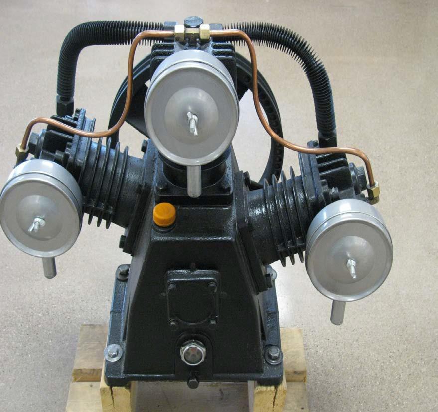
3 Operating Instructions Model PP15V120Y3 PP15H120Y3 PP20H120V3 PP25H120V3 Description 15 Hp 15 Hp 20 Hp 25 Hp Three Phase Three Phase Three Phase Three Phase 175 psi Max PSI Motor HP 15 Hp 15 Hp 20 Hp 25 Hp Motor RPM Voltage 208/230/460/ /230/460/ /230/460/ /230/460/575 Tank Size Polar Air Electric Operated, Two-Stage, Hp Piston Air Compressors 120 Gallon 120 Gallon 120 Gallon 120 Gallon Vertical Horizontal Horizontal Horizontal Pump Model APP3Y2062T APP3Y2062T APP4V2598T APP4V2598T Pump RPM Noise DB(A) Outlet Connection NPT 1 NPT 1 NPT 1 NPT 2 L W H Dimensions (inches) 33 x 24 x x 32 x x 30 x x 30 x 51 Weight (lbs.) Shipping Weight Description Unit configuration and appearance varies by model. Callouts are for general identification. Unloader line Air filter Beltguard Electric motor Belt tensioner plate Pump oil drain valve Pressure switch with unloader Check valve Ball valve (Air outlet) Raised pump mounting brackets Oil site glass Air receiver / Tank Pilot valve (Pressure relief) Pressure gauge Tank anchor bolt location (4, typ.) Dual Timer Electronic auto drain (not included on all models) 3
4 Polar Air Electric Operated, Piston Compressors Safety This manual contains very important information to know and understand. This is provided for SAFETY and to PREVENT EQUIPMENT PROBLEMS. To help understand this information, observe the following: Danger indicates an imminently hazardous situation which, if not avoided, will result in death or serious injury. Warning indicates a potentially hazardous situation which, if not avoided, could result in death or serious injury. Caution indicates a potentially hazardous situation which, if not avoided, may result in minor or moderate injury. Notice indicates important information, that if not followed, may cause damage to equipment. MANUAL Basic Guidelines Read all manuals included with this product carefully. Be thoroughly familiar with the controls and the proper use of the equipment. CALIFORNIA PROPOSITION 65 This product or its power cord may contain chemicals known to the State of California to cause cancer and birth defects or other reproductive harm. Wash hands after handling. 1. Allow only trained, authorized persons who have read and understood these operating instructions to use this compressor. Failure to follow the instructions, procedures and safety precautions in this manual can result in accidents and injuries. 2. NEVER start or operate the compressor under unsafe conditions. Tag the compressor, disconnect and lock out all power to it to prevent accidental start-up until the condition is corrected. 3. Install, use and operate the compressor only in full compliance with all pertinent OSHA regulations and all applicable Federal, State & Local Codes, standards and regulations. 4. NEVER modify the compressor and/or controls in any way. 5. Keep a first aid kit in a convenient place. Seek medical assistance promptly in case of injury. Avoid infection by caring for any small cuts and burns promptly. Breathable Air 1. NEVER use air from this compressor for breathable air except in full compliance with OSHA Standards 29 CFR 1910 and any other Federal, State or Local codes or regulations. Death or serious injury can result from inhaling compressed air without using proper safety equipment. See OSHA standards on safety equipment. 2. DO NOT use air line anti-icer systems in air lines supplying respirators or other equipment used to produce breathable air. DO NOT discharge air from these systems in unventilated or other confined areas. Pressurized Components This equipment is supplied with a ASME designed pressure vessel protected by an ASME rated relief valve. Pull the ring before each use to make sure the valve is functional. Refer to figure 10. DO NOT attempt to open valve while the machine is under pressure. Personal Protective Equipment Be sure all operators and others around the compressor and its controls comply with all applicable OSHA, Federal, State and Local regulations, codes and standards relating to personal protective equipment. This includes respiratory protective equipment, protection for the extremities, protective clothing, protective shields and barriers, electrical protective equipment, and personal hearing protective equipment. Inspection Inspect compressor prior to any use. Check for external damage that might have occurred during transit. Be careful of moving parts then test pulley by turning it freely by hand. Report any damage to delivery carrier immediately. Make sure pallet-mounted compressors are firmly secured to the pallet before moving. NEVER attempt to move a compressor that is not secure as serious injury or property damage could occur. A forklift may be necessary for unloading the Polar Air compressor. Use all forklift safety measures and require a certified forklift operator. Refer to figure 1 for safe unloading procedure. 4
5 Operating Instructions Forklift Safety 1. Make sure lift operator stays aware while moving compressor. 2. Be sure load is secure and well balanced before moving the compressor. 3. Make sure forks are fully engaged and level before lifting or moving compressor. 4. Keep load as low as possible and observe safe operating practices. Keep unit level and be careful of top heavy load Figure 1: Keep unit level Lifting Safety 1. Carefully inspect all lifting equipment and make sure it is in good condition. Rated capacity should exceed compressor weight. Make sure lifting hook has a functional safety latch or equivalent and is properly attached to lifting feature. 2. Make sure lifting points are in good condition and tighten any loose nuts or bolts before lifting. 3. Use provided lifting feature or appropriate sling. A sling must be used when moving compressor with a helicopter or other air-borne equipment. Be sure to follow OSHA standards 29 CFR 1910 Subpart N. 4. Use guide ropes or equivalent to prevent twisting or swinging of the compressor while it is in the air and NEVER attempt to lift in high winds. Keep compressor as low to the ground as possible. 5. Keep persons away and make sure no one is under the compressor while it is lifted. 6. Only use lifting features provided for entire compressor package. NEVER use bolts or other hooks on invididual components to move the compressor. 7. Make sure to put compressor on a level surface that can support the weight of the compressor and loading equipment. Do not operate unit if damaged during shipping, handling or use. Damage may result in bursting and cause injury or property damage. Installation Area 1. Install compressor in a clean, dry and well-lit area. Be sure installation area can maintain a temperature range between F. If ambient temperature drops below 32 F, be sure to protect safety/relief valves and drain valves from freezing. NEVER operate compressor with temperatures below 15 F or above 125 F. 2. Allow sufficient space around compressor for maintenance access and adequate airflow. Mount unit with pulley towards wall and leave a minimum of 15 inches of clearance. 3. Use shims to level compressor if installation area is not flat. This will avoid excessive vibration and premature pump wear. DO NOT install compressor in boiler room, paint spray room, or area where sandblasting occurs. Make sure inlet air is away from exhaust fumes or other toxic, noxious or corrosive fumes or substances. 4. If acid is used in operating environment or air is dust laden, pipe intake to outside, fresh air. Increase pipe size by one size for every 20 feet of run. Be sure to install protective hood around intake filter. 5. In operating environments where excessive water, oil, dirt, acid or alkaline fumes are present, a TEFC (totally enclosed, fan cooled) motor is recommended. Check nameplate for motor type. 6. Insulate cold water or other low temperature pipes that pass overhead to avoid condensation dripping on compressor which could cause rust and/or motor shorting. Piping Safety Steps 1. Install appropriate flow-limiting valves as necessary according to pipe size(s) used and run lengths. This will reduce pressure in case of hose failure, per OSHA Standard 29 CFR (b)(7). 2. Flow-limiting valves are listed by pipe size and rated CFM. Select appropriate valves accordingly, in accordance with the manufacturer s recommendations. 5
6 Polar Air Electric Operated, Piston Compressors Piping / Tank Installation 1. Place tank feet on 1/4 thick rubber pads. Thicker padding will increase vibration and the possibility of cracking the tank or other unit damage. Do not place unit on dirt floor or uneven surface. 2. Fasten anchor bolts snugly but do not overtighten so normal vibration will not damage unit. Compressor unit is top heavy and must be bolted to solid, flat surface to avoid falling and premature pump wear. Splash lubrication will not operate properly if unit is not level. 3. Use a flexible connector between compressor tank and piping system to minimize noise, vibration, unit damage, and pump wear. 4. Install appropriate ASME code safety valves and make sure piping system is equipped with adequate condensate drains. See figure 2. Refer to figure 3 for recommended closed loop installation. Ball Valve Coalescing Filter with Auto Drain To Shop Piping Minimum Pipe Size For Compressed Air Lines (Pipe size shown in inches) Length Of Piping System SCFM 25 ft. 50 ft. 100 ft. 250 ft. 20 3/4 3/4 3/ / / / /4 1-1/4 1-1/2 1-1/2 PLAN VIEW Closed loop system Install tee fitting in piping from air supply to minimize pressure drop and to allow airflow in two directions. Air Drop: Install tee fitting with branch to top to minimize condensation in air drop ELEVATION Air Drop (typ.) From Compressor Water trap with drain Air Tank Air Dryer From Compressor To Air Tool Water Drain Valve Figure 3: Closed Loop Installation Figure 2: Basic Piping Diagram Never install a shut-off valve such as a glove or gate valve, between the pump discharge and the air tank unless a safety valve is installed in the line between valve and pump. 5. Make sure any tube, pipe or hose connected to the unit can withstand operating temperatures and retain pressure. Never use plastic (PVC) pipe for compressed air. Serious injury or death could result. 6. Never use reducers in discharge piping. Keep all piping and fittings the same size in the piping system. 7. For permanent installations of compressed air systems, determine total length of system and select correct pipe size. Make sure underground lines are buried below frost line and avoid areas where condensation could build up and freeze. 8. Test entire piping system before underground lines are buried. Be sure to find and repair all leaks before using compressor. Never exceed recommended pressure or speed while operating compressor. Electronic Auto Drain (if equipped) One auto drain can be used for multiple compressor units. Install necessary piping with appropriate fittings. 6
7 Operating Instructions Not included on all units Pipe to tank outlet(s) Manual OPEN/ CLOSE valve ON Figure 4: Auto Drain Feature 1. Plug auto drain into 120V outlet. 2. Set timers to desired settings. See figure 4. If drain is used for multiple units, increase timer settings as needed. 3. Use test button to check proper operation. Refer to maintenance section for proper care. Electrical Safety Be sure only trained and authorized personnel install and maintain this compressor in accordance with all applicable federal, state and local codes, standards and regulations. Follow all NEC (National Electric Code) standards especially those concerning equipment grounding conductors. 1. Follow all NEC and local codes for electrical wiring. Allow only authorized Polar Air service person or certified electrician to install electrical components. 2. Put unit on dedicated circuit and make sure no other electrical equipment is wired into it. Failure to wire unit on independent circuit can cause circuit overload and/or imbalance in motor phasing. Install proper No Fuse Breaker (NFB) according to kw output of compressor. 3. Ensure incoming service has adequate ampere rating. 4. Ensure supply line has the same electrical characteristics (voltage, cycles and phase) as the electric motor. 5. Refer to amp load information on motor tag and use correctly sized wiring. Be sure to consider distance between power supply and machine. 6. Install surge protection device between power supply and compressor motor. 7. Make sure to install properly sized breakers and fuses. 8. The unit must be properly grounded. DO NOT connect ground wire to air or cooling lines. TEST OFF ON SEC OFF MIN Drain interval Drain time Filter access Clean regularly, see Fig 13. Improperly grounded electrical components are shock hazards. Make sure all the components are properly grounded to prevent death or serious injury. 9. Make sure proper overload protection for the motor is installed. Wiring Installation Install power leads into terminals opposite motor wires. When wiring unit with magnetic starter, do not install power directly to pressure switch to avoid possible fire and property damage. Ensure power supply and internal wiring is adequate according to voltage and frequency stated on motor nameplate and starter. Voltage should not vary more than 12% to ensure proper operation of compressor. Single Phase Motors - No Magnetic Starter 1. Connect first power lead to 1L1. 2. Connect second power lead to 3L2. 3. Connect ground wire to existing motor ground wire. Power 1 Breaker Power Supply 220 V Power 2 110V Power Wires Common ground wire Motor Starter Figure 5: Single Phase Wiring Diagram without magnetic starter Motor Single Phase Motors - With Magnetic Starter 1. Connect first power lead to 1L1. Leave existing jumper wire installed. See Figure Connect second power lead to 3L2. Leave existing jumper wire installed. 3. Connect ground wire to ground lug. 4. Ensure all wiring and terminals are properly tightened
8 Polar Air Electric Operated, Piston Compressors Power 1 Breaker Power Supply 220 V Power 2 Common ground wire Wire connection from coil to pressure switch Power 1 Breaker Power Supply 220 V Power 2 Power 3 Common ground wire Wire connection from coil to pressure switch A1 A2 Pressure Switch A1 A2 Pressure Switch 1L1 3L2 5L3 1L1 3L2 5L3 110V Power Wires Jumper wire from 3L2 power to NC96 Jumper wire from 1L1 to top of selector switch ON-OFF Selector Switch (if equipped) NC 96 Mag A2 Starter T1 T2 T3 Thermal Overload T1 T2 T3 NC 95 Jumper wire from bottom of selector switch to pressure switch Jumper wire from NC95 to A2 Large jumper wire 5L3 to T2 on overload Motor 110V Power Wires Jumper wire from 3L2 power to NC96 Jumper wire from 1L1 to top of selector switch ON-OFF Selector Switch (if equipped) NC 96 Mag Starter T1 T2 T3 Thermal Overload T1 T2 T3 A2 NC 95 Motor Jumper wire from bottom of selector switch to pressure switch Jumper wire from NC95 to A2 Three Phase Motors (See figure 7) 1. Connect first power lead to 1L1. 2. Connect second power lead to 3L2. 3. Connect third power lead to 5L3. 4. Connect ground wire to existing motor ground wire. 5. Check for proper motor rotation. When facing motor shaft, pulley should turn counterclockwise. If rotation is reversed, turn off power then switch two power leads. Ensure wiring is installed according to voltage required for proper motor operation (220V or 460V). Operation Figure 6: Single Phase Wiring Diagram with magnetic starter Safety Rules 1. Make sure all operators receive product training, read and understand all instructions. Keep all flammable, combustible, poisonous and noxious materials away from operating area. Make sure there are no oily rags, trash, leaves, litter or other combustible materials in operating area. Keep suitable, fully charged fire extinguishers nearby when servicing and operating the compressor. Figure 7: Three Phase Wiring Diagram with magnetic starter 2. NEVER allow modifications to compressor structure or controls. 3. Keep all ignition sources away from exposed electrical parts. 4. Keep all persons clear of compressor during start-up and operation. 5. NEVER operate the compressor with the fan, coupling or other guards removed. 6. DO NOT engage in horseplay with air hoses as death or serious injury may result. 7. Make sure to provide adequate ventilation and use proper lubricant while operating the compressor. If lubricant or other combustible substances are spilled, clean up immediately. 8. When checking or adding lubricant or when refilling air line anti-icer systems with antifreeze compound, shut off compressor and allow it to cool. Keep sparks, flames and other ignition sources away and DO NOT permit smoking in the vicinity. 9. Stop compressor and disconnect power if a hazardous condition arises. 10. Wear snug fitting clothing and confine long hair when around compressor. Keep all body parts and clothing away from couplings, flywheel and other moving parts of the equipment. 8
9 Operating Instructions Keep all persons away from the discharge opening of hoses or tools or other points of compressed air discharge. If the machine is installed in an enclosed area, be sure to vent the relief valve outside of the structure or to an unoccupied area. 11. DO NOT use air tools that are rated below the maximum rating of the compressor. Select air tools, air hoses, pipes, valves, filters and other fittings accordingly. DO NOT exceed manufacturer s rated safe operating pressures for these items. 12. Make sure all hose connections are adequately secured to prevent tools or hose ends from being accidentally disconnected. Start-Up 1. This unit is shipped with pump break-in oil and should be ready to operate. Be sure to check for proper oil level before operating the compressor. Oil should be in center of site glass. See figure 8. Use only Airbase Industries oil (PN: APOL03000G1). Use of any other product will cause product damage and void the warranty. 2. Check for proper belt tension. There should be 1/2 inch slack. Refer to maintenance section if adjustment is necessary. Always make sure main power is off before touching belts or other moving parts of compressor. 3. Lightly push power switch to make sure system is working. 4. If motor shaft is not turning counter clockwise, disconnect power to terminal block then exchange any two of the three power leads. Re-check rotation. Figure 8: Check proper oil level Oil level should be to center of red circle in site glass Continuous Run Feature (if equipped) For heavy use applications such as sandblasting, the continuous run feature is available. This feature keeps main feed line open to eliminate numerous motor starts/stops and to help cool pump. To engage continuous run feature, open ball valve found by following copper tubing across cylinder heads to tank. See figure 9. Stop continuous run feature by closing valve so compressor will start and stop according to pressure switch. Maintenance To pump unloaders Figure 9: Continuous run feature Open ball valve to engage continuous run feature Safety Steps Disconnect, tag and lock out power source then release all pressure from the system before attempting to install, service, relocate or perform ANY maintenance. 1. Make sure repairs are done in a clean, dry, well lighted and ventilated area. 2. When cleaning, use air pressure less than 30 psig (2.1bar). NEVER use flammable solvents for cleaning purposes. Also use effective chip guarding and personal protective equipment per OSHA standard 29 CFR (b). 3. Relieve all internal pressure prior to opening any line, fitting, hose, valve, drain plug, connection or other component, such as filters and line oilers, and before refilling optional air line anti-icer systems with antifreeze compound. 4. Keep electrical wiring, including all terminals and pressure connectors in good condition. Replace any wiring that has cracked, cut, or otherwise damaged insulation. Replace terminals that are worn, discolored or corroded. Keep all terminals and pressure connectors clean and tight. 9
10 Polar Air Electric Operated, Piston Compressors 5. Keep all body parts and any hand-held tools or other conductive objects away from exposed live parts of the electrical system. When making repairs or adjustments, stand on a dry, insulated surface and DO NOT contact any other portion of the compressor. 6. DO NOT leave compressor unattended with exposed electrical components. Be sure to tag and disconnect all power if temporary absence is necessary. Compressor components can become hot during operation. Avoid bodily contact with hot liquids, hot surfaces and sharp edges and corners. Belt Adjustment Be sure to relieve all system pressure then lock out power and tag compressor to prevent unexpected movement of the unit. Inspect belt tension after first 30 hours of operation then every 30 days. 1. Proper belt tension is determined by pressing on belt midway between motor pulley and flywheel. There should be approximately 1/2 inch of 1/2 Deflection deflection. Fig. 10: Proper belt tension 2. Adjust belt tension as needed by loosening the four motor frame nuts then adjusting single bolt head on belt tensioner. See figure 11. Remember to tighten motor bolts after adjustment is made. 3. Always replace all belts with the same brand, at the same time. Make sure belts are unimatched. Do not replace belts independently. Figure 11: Belt adjustment Loosen motor bolts (all 4 mounts) Belt tensioner bolt Figure 12: Safety Valve 4. Do not splash lubricating oil on belts or pulleys when adjusting or replacing belts. Not included on all units 1. Close manual valve. 2. Remove filter cap and filter. 3. Clean filter. 4. Reassemble drain. 5. Open manual valve. Manual OPEN/CLOSE valve Pull ring on safety valve before each use. Changing Oil All units are shipped with break-in oil. Change oil within first 50 hours or 30 days of operation, whichever comes first. DO NOT use automotive type oil. Use only Airbase Industries Oil (PN: APOL03000G1). Use of any other product will cause product damage and void the warranty. Change oil every 90 days or if oil becomes milky. Safety Valve NEVER attempt to regulate or tamper with safety valve. Valve is sealed and certified by ASME code and is designed to relieve system pressure when necessary. Check proper operation of safety valve before each use. Refer to figure 12. If valve does not open manually, replace immediately. Discharge pressure is generally set at 175 PSI (12.1 bar). DO NOT attempt to open valve while machine is under pressure. Tank Drain daily. If unit is equipped with electronic auto drain: 1. Check daily to ensure proper operation. 2. Clean filter daily. Refer to figure 13. ON TEST OFF ON SEC OFF MIN Auto drain filter Filter cap Figure 13: Clean filter in automatic drain 10
11 Operating Instructions Maintenance Schedule Daily Weekly Check oil level Check for unusual operation. Correct before damage occurs. Clean air filter Change oil (after first 50 hours) Check safety valve Drain tank and traps General unit cleaning Check for unusual operation. Correct before damage occurs. Monthly Every 3 months Check and tighten all bolts as required Check all connections for air leaks Check belts for proper tension, wear, and alignment Change oil Inspect oil for contamination. Change if necessary. Check all unloading lines for leaks. Air leaks in unloader lines will cause unloaders and pilot valve to chatter and could cause short cycling of motor. Inspect valve assemblies Troubleshooting Chart Problem Possible Causes Resolutions Low air pressure 1. Clogged inlet filter 2. Air leak(s) in system 3. Application exceeds rated air output of compressor 4. Cylinder head valves not sealing 5. Insufficient power 1. Disassemble valve, clean thorougly 2. Use soapy water to locate leaks, replace or tighten threaded parts 3. Check CFM requirements, change tool or use compressor with higher air output 4. Remove valves from cylinder head, repair or replace as necessary 5. Check power supply, rewire as necessary Overheating 1. Duty cycle exceeded 2. Improper rotation 3. Head valve(s) not seating properly 4. Blown cylinder head gasket(s) 5. Restriction in head, intercooler or check valve 6. Low oil 1. Keep duty cycle at 60/40 to maintain pump life 2. When facing flywheel, ensure counter-clockwise rotation 3. Clean or replace 4. Replace gasket(s) 5. Clear blockage 6. Add oil. Ensure oil level is at middle of site glass. See figure 8. Use only Airbase Industries Oil (PN: APOL03000G1). Use of any other product will cause product damage and void the warranty. 7. Dirt in intercooler fins or cylinder fins 8. Poor ventilation / ambient temperature too high Use low pressure air to blow dirt away from compressor 8. Increase ventilation around operating area. Ensure compressor has adequate clear space from walls and other possible obstructions. Ambient temperature should not exceed 110 F.
12 Polar Air Electric Operated, Piston Compressors Warranty Statement EATON COMPRESSOR AND FABRICATION CO., INC. (and each of its subsidiaries, including POLAR AIR COMPRESSORS, INC.) makes the following Warranties: 1. THAT EACH ROTARY SCREW AIR COMPRESSOR PUMP TO BE FREE FROM DEFECTS IN MATERIAL, WORKMANSHIP, AND PARTS FOR 10 YEARS ON THE ROTARY SCREW AIR COMPRES- SOR PUMP FROM THE DATE OF PURCHASE. Eaton Compressor and Fabrication Co., Inc. (and each of its subsidiaries) is not responsible for downtime during warranty service. If downtime is necessary, it is the Purchaser s discretion and obligation (at Purchaser s expense) to have a redundant UNIT. This warranty applies to rotary screw rotors and bearings. The electric motor carries a five year warranty and a 2 year warranty on the rest of the compressor unit. The screw compressor MUST have Eaton Compressor and Fabrication Co., Inc. Lubricant Synthetic exclusively, the same which must be purchased from Eaton Compressor and Fabrication Co., Inc. (Mixing different brands of oil will void this warranty and cause the rotors to varnish). All air filters, oil filters, and oil separator filters must be purchased from Eaton Compressor and Fabrication Co., Inc. and the screw compressor must have Eaton Compressor and Fabrication Co., Inc. Synthetic Rotary Screw oil, purchased exclusively from Eaton Compressor and Fabrication Co., Inc., for this warranty to apply. Annual participation in all oil programs are required by original purchaser of the unit outlined by the following: a) Purchase an oil sample kit for oil analysis by Eaton Compressor and Fabrication Co., Inc. b) Oil sample kit contains 20 oil sample containers. One (1) oil sample is to be sent for analysis by an Eaton Compressor oil analysis laboratory every six (6) months so oil can be tested twice yearly. c) Oil samples are obtained by draining 4 ozs. of oil into container then mailing sample container to laboratory address provided in oil sample kit. d) The laboratory will perform an oil analysis then a report to address required when oil sample is provided. e) Provide annual proof of purchase for oil/filter service kit. f) Maintain proper oil level in unit at all times. If the unit runs out of oil, this warranty is void. Failure of original purchaser to comply with any of the above conditions pertaining to oil analysis with void the complete unit warranty. A full detailed maintenance schedule must be sent to Eaton Compressor and Fabrication Co., Inc. once a year with the total service completed quarterly, outlining each air filter, oil filter and oil change with the total hours on the unit after each maintenance was performed. Failure to fully comply with this warranty and fully comply with the manual herein will void this warranty. Exclusions to this warranty also include all normal wear and tear items, including, but not limited to the bearings, rotors, valves, belts, shaft seal and load/unload solenoids. 2. THAT EACH BARE COMPRESSOR PUMP UNIT TO BE FREE FROM DEFECTS IN MATERIAL, WORKMANSHIP, AND PARTS FOR 5 YEARS FOR THE UNIT FROM THE DATE OF PURCHASE. Eaton Compressor and Fabrication Co., Inc. (and each of its subsidiaries) is not responsible for downtime during warranty service. If downtime is necessary, it is the Purchaser s discretion and obligation (at Purchaser s expense) to have a redundant UNIT. Warranty repairs shall not include freight costs. Purchaser is responsible for returning unit to Eaton Compressor and Fabrication Co., Inc. This pump must have Eaton Compressor and Fabrication Co., Inc. lubricant Synthetic exclusively, the same which must be purchased from Eaton Compressor and Fabrication Co., Inc. (Mixing different brands of oils will void the pump warranty). A service kit must be purchased from Eaton Compressor and Fabrication Co., Inc. for this warranty to apply. Service kits contain an air filter and synthetic oil that must be changed annually. Annual proof of purchase of all oil programs must be maintained by the original purchaser of the compressor pump. If the unit runs out of oil, this warranty is void. Failure to fully comply with this warranty and fully comply with the manual herein will void this warranty. Exclusions include: service such as OIL CHANGES, FILTER REPLACEMENTS, GASKET TIGHTENING TO CORRECT OIL SEEPAGE or DRIVE BELT TIGHTENING and VALVE CLEANING and are not covered under warranty. Warranty shall be void under the following conditions: Failure to routinely change oil and to maintain a clean filter, or exceeding 70% duty cycle resulting in overheating and excessive wear and tear, or exposing electrical components to rain or water, or installing the unit in a hostile environment such as acid vapors or any caustic or abrasive matter that may be ingested into the pump, or installing the unit in an enclosed area where lack of cooling ventilation is present, such as in boiler or equipment rooms where the ambient air exceeds 100 F. 3. THAT EACH COMPRESSOR UNIT TO BE FREE FROM DEFECTS IN MATERIAL, WORKMANSHIP, AND PARTS FOR 5 YEARS FOR THE COMPRESSOR PUMP AND 2 YEARS ON THE REMAINDER OF THE UNIT FROM THE DATE OF PURCHASE. The UNIT also carries a 1-year labor warranty. Eaton Compressor and Fabrication Co., Inc. (and each of its subsidiaries) is not responsible for downtime during warranty service. If downtime is necessary, it is the Purchaser s discretion and obligation (at Purchaser s expense) to have a redundant compressor. Warranty repairs shall not include freight costs. Purchaser is responsible for returning unit to Eaton Compressor and Fabrication Co., Inc. This pump MUST have Eaton Compressor and Fabrication Co., Inc. Lubricant Synthetic exclusively, the same which must be purchased from Eaton Compressor and Fabrication Co., Inc. (Mixing different brands of oil will void this warranty). A service kit must be purchased from Eaton Compressor and Fabrication Co., Inc. for this warranty to apply. Service kits contain an air filter and synthetic oil that must be changed annually. Annual proof of purchase of all oil programs must be maintained by the original purchaser of the compressor unit. If the unit runs out of oil, this warranty is void. Failure to fully comply with this warranty and fully comply with the manual herein will void this warranty. Exclusions include: service such as OIL CHANGES, FILTER REPLACEMENTS, GASKET TIGHTENING TO CORRECT OIL SEEPAGE or DRIVE BELT TIGHTENING and VALVE CLEANING and are not covered under warranty. Warranty shall be void under the following conditions: Failure to routinely change oil and to maintain a clean filter, or exceeding 70% duty cycle resulting in overheating and excessive wear and tear, or exposing electrical components to rain or water, or installing the unit in a hostile environment such as acid vapors or any caustic or abrasive matter that may be ingested into the pump, or installing the unit in an enclosed area where lack of cooling ventilation is present, such as in boiler or equipment rooms where the ambient air exceeds 100 F. 4. THAT EACH DRYER UNIT TO BE FREE FROM DEFECTS IN MATERIAL, WORKMANSHIP, AND PARTS FOR 5 YEARS on the HEAT EXCHANGER AND 2 YEARS ON THE DRYER UNIT FROM THE DATE OF PURCHASE. Eaton Compressor and Fabrication Co., Inc. (and each of its subsidiaries) is not responsible for downtime during warranty service. If downtime is necessary, it is the Purchaser s discretion and obligation (at Purchaser s expense) to have a redundant DRYER UNIT. Warranty repairs shall not include freight costs. Purchaser is responsible for returning unit to Eaton Compressor and Fabrication Co., Inc. Each DRYER UNIT must have a coalescing filter attached to the intake of the dryer to remove any oil or dirt before air enters the dryer. Failure to install coalescing filter will void the warranty. 5. GENERAL PROVISIONS: Eaton Compressor and Fabrication Co., Inc. (and each of its subsidiaries) is not responsible for downtime during warranty service. If downtime is necessary, it is the Purchaser s discretion and obligation (at Purchaser s expense) to have a redundant compressor. Warranty repairs shall not include freight costs. If necessary, the Purchaser is responsible for returning unit and/or applicable part(s) to Eaton Compressor and Fabrication Co., Inc. Exclusions include: service such as OIL CHANGES, FILTER REPLACEMENTS, GASKET TIGHTENING TO CORRECT OIL SEEPAGE or DRIVE BELT TIGHTENING and VALVE CLEANING and are not covered under warranty. Further Exclusions include failure to fully and completely follow the guidelines set forth in the manual. Of specific note is where a product is used where granite and/or concrete work is performed or conditions are dusty and the product is required to be housed in a separate room from the adverse conditions where the product has access to fresh air intake. Parts used for warranty purposes must be supplied by Eaton Compressor and Fabrication Co., Inc. Warranty work will be performed by an approved Eaton Compressor and Fabrication Co., Inc. Technician. If any maintenance (other than routine maintenance) is performed by a non-approved Eaton Compressor and Fabrication Co., Inc. Technician, written pre-approval must be obtained from Eaton Compressor and Fabrication Co., Inc. to prevent voiding this Warranty. Failure to fully comply with this warranty and fully comply with the manual herein will void this warranty. All warranties are nontransferable. The Oil Purchase Program is effective as of January 1,
13 Operating Instructions SPLASH LUBRICATED AIR COMPRESSOR PUMPS Airbase Industries designs and manufactures products for safe operation. However, operators and maintenance persons are responsibile for maintaining safety. All safety precautions are included to provide a guideline for minimizing the possibility of accidents and property damage while equipment is in operation. Keep these instructions for reference. Unit configuration and appearance varies by model. Contents Page No. Model Specification Charts... 2 Safety Information... 3 Tag Definitions... 3 Basic Guidelines... 3 Breathable Air... 3 Personal Protective Equipment... 3 Inspection... 3 Installation... 3 Area... 3 Piping Safety Steps... 4 Tank Installation... 4 Pump Installation... 5 Page No. Operation... 6 Safety Rules... 6 Start Up... 6 Maintenance... 7 Safety Steps... 7 Belt Adjustment... 7 Changing Oil... 7 Maintenance Schedule... 7 Troubleshooting... 8 Warranty... 8 AMNU
14 Splash Lubricated, Air Compressor Pumps SINGLE STAGE Splash Lubricated, Air Compressor Pumps Model APP2V0313S APP3Y0518S APP2V0732S Description 3HP 5HP 7.5HP CFM Displacement Pressure (100 psi) Max PSI Noise DB(A) Outlet Connection NPT 1/2 NPT 1/2 NPT 3/4 Pump RPM Bolt Pattern 8-3/16 x 4-5/8 8-1/4 x 5-1/4 10-1/4 x 5-3/8 L W H Dimensions (inches) 15 x 10 x x 15 x x 15 x 12 Weight (lbs.) Belt Type (A or B) A A B Number of Belts TWO STAGE Splash Lubricated, Air Compressor Pumps Model APP3Y0521T APP2I0524T APP3Y0732T APP4V1043T APP3Y1544T APP3Y2062T APP4V2598T Description 5HP - 3cyl 5HP- 2cyl 7.5HP 10HP 15HP 20HP 25HP CFM Displacement Pressure (100 psi) Max PSI Noise DB(A) Outlet Connection NPT 3/4 NPT 3/4 NPT 3/4 NPT 3/4 NPT 1-1/4 NPT 1-1/4 NPT 1-1/4 Pump RPM Bolt Pattern 9-7/8 x 6-1/2 7-3/4 x 9 9-7/8 x 6-1/2 9-1/4 x 9-1/4 13-1/2 x 6-3/4 13-1/2 x 6-3/4 13-5/8 x 12 5/8 L W H Dimensions (inches) 25 x 13 x x 14 x x 13 x x 21 x x 14 x x 14 x x 29 x 26 Weight (lbs.) Belt Type (A or B) B B B B B B B No. of Belts
15 Operating Instructions Safety This manual contains very important information to know and understand. This is provided for SAFETY and to PREVENT EQUIPMENT PROBLEMS. To help understand this information, observe the following: Danger indicates an imminently hazardous situation which, if not avoided, will result in death or serious injury. Warning indicates a potentially hazardous situation which, if not avoided, could result in death or serious injury. Caution indicates a potentially hazardous situation which, if not avoided, may result in minor or moderate injury. Notice indicates important information, that if not followed, may cause damage to equipment. MANUAL Read all manuals included with this product carefully. Be thoroughly familiar with the controls and the proper use of the equipment. Basic Guidelines 1. Allow only trained, authorized persons who have read and understood these operating instructions to use this compressor pump. Failure to follow the instructions, procedures and safety precautions in this manual can result in accidents and injuries. 2. NEVER start or operate the compressor pump under unsafe conditions. Tag the compressor, disconnect and lock out all power to it to prevent accidental start-up until the condition is corrected. 3. Install, use and operate the compressor pump only in full compliance with all pertinent OSHA regulations and all applicable Federal, State & Local Codes, standards and regulations. 4. NEVER modify the compressor pump and/or controls in any way. 5. Keep a first aid kit in a convenient place. Seek medical assistance promptly in case of injury. Avoid infection by caring for any small cuts and burns promptly. Breathable Air 1. NEVER use air from this compressor pump for breathable air except in full compliance with OSHA Standards 29 CFR 1910 and any other Federal, State or Local codes or regulations. Death or serious injury can result from inhaling compressed air without using proper safety equipment. See OSHA standards on safety equipment. 2. DO NOT use air line anti-icer systems in air lines supplying respirators or other equipment used to produce breathable air. DO NOT discharge air from these systems in unventilated or other confined areas. Personal Protective Equipment Be sure all operators and others around the compressor and its controls comply with all applicable OSHA, Federal, State and Local regulations, codes and standards relating to personal protective equipment. This includes respiratory protective equipment, protection for the extremities, protective clothing, protective shields and barriers, electrical protective equipment, and personal hearing protective equipment. Inspection Inspect compressor pump prior to any use. Check for external damage that might have occurred during transit. Be careful of moving parts then test pulley by turning it freely by hand. Report any damage to delivery carrier immediately. Do not operate unit if damaged during shipping, handling or use. Damage may result in bursting and cause injury or property damage. Installation Area 1. Install compressor pump in a clean, dry and well-lit area. Be sure installation area can maintain a temperature range between F. 2. Insulate cold water or other low temperature pipes that pass overhead to avoid condensation dripping on compressor which could cause rust and/or motor shorting. DO NOT install compressor in boiler room, paint spray room, or area where sandblasting occurs. Make sure inlet air is away from exhaust fumes or other toxic, noxious or corrosive fumes or substances. 3
16 Splash Lubricated, Air Compressor Pumps 3. If acid is used in operating environment or air is dust laden, pipe intake to outside, fresh air. Increase pipe size by one size for every 20 feet of run. Be sure to install protective hood around intake filter. 4. In operating environments where excessive water, oil, dirt, acid or alkaline fumes are present, a TEFC (totally enclosed, fan cooled) motor is recommended. Check nameplate for motor type. 5. Allow sufficient space around compressor pump for maintenance access. Mount unit with pulley towards wall and leave a minimum of 15 inches of clearance. 6. Use shims to level compressor if installation area is not flat. This will avoid excessive vibration and premature pump wear. Piping Safety Steps 1. Install appropriate flow-limiting valves as necessary according to pipe size(s) used and run lengths. This will reduce pressure in case of hose failure, per OSHA Standard 29 CFR (b)(7). 2. Flow-limiting valves are listed by pipe size and rated CFM. Select appropriate valves accordingly, in accordance with the manufacturer s recommendations. Tank Installation 1. Place tank feet on 1/4 thick rubber pads. Thicker padding will increase vibration and the possibility of cracking the tank or other unit damage. Do not place unit on dirt floor or uneven surface. 2. Fasten anchor bolts snugly but do not overtighten so normal vibration will not damage unit. Compressor unit is top heavy and must be bolted to solid, flat surface to avoid falling and premature pump wear. Splash lubrication will not operate properly if unit is not level. Pump Installation 1. Mount pump to deck of tank then connect main feed port to check valve in tank. See figure For units with centrifugal unloader system, install 1/4 copper tubing from 90 elbow (located in front of crankcase) to the unloader port of check valve. Check valve Figure 1: Connect feed port to check valve NOTE: If pump is not equipped with centrifugal unloader, install an unloader line from the check valve unloader port to the unloader port of the pressure switch. This will relieve head pressure when unit stops and provide no-load restarting. 3. Cap fitting on cylinder heads if not using pilot valve for continuous run port. 4. Make sure there is a 1/4 copper tube (unloader tube) installed from tank check valve to unloader on pressure switch. This relieves head pressure when compressor stops for easier restart. See figure 2. Figure 2: Install unloader line from check valve to pressure switch 5. Use proper pulley for motor. Refer to Pulley Size Chart for correct sizing. 6. Install belts. There should be 1/2 slack for proper belt tension. See figure Use a flexible connector between compressor tank and piping system to minimize noise, vibration, unit damage, and pump wear. 1/2 deflection Figure 3: Proper belt tension Pressure switch with unloader 4
17 Operating Instructions Pulley Size Chart (Pulley size in inches) Pump Electric 1750 RPM 3450 RPM Gas Engine Gas Engine Model No. Motor - Hp 4 Pole Motor 2 Pole Motor Hp Pulley Size APP2V0313S APP3Y0518S APP3Y0518S APP3Y0521T APP2V0732S APP2I0524T APP3Y0732T APP3Y0732T APP4V1043T APP4V1043T APP3Y1544T APP3Y2062T APP4V2598T APP4V2598T Splash lubricated pumps require 550 RPM for proper lubrication. Be sure to size motor and engine pulleys correctly. 8. Install appropriate ASME code safety valves and make sure piping system is equipped with adequate condensate drains. See figure 4. Never install a shut-off valve such as a glove or gate valve, between the pump discharge and the air tank unless a safety valve is installed in the line between valve and pump. 9. Make sure any tube, pipe or hose connected to the unit can withstand operating temperatures and retain pressure. Never use plastic (PVC) pipe for compressed air. Serious injury or death could result. 10. Never use reducers in discharge piping. Keep all piping and fittings the same size in the piping system. 11. For permanent installations of compressed air systems, determine total length of system and select correct pipe size. Make sure underground lines are buried below frost line and avoid areas where condensation could build up and freeze. Air Tank Ball Valve Coalescing Filter with Auto Drain Water Drain Valve Figure 4: Basic Piping Diagram To Shop Piping Air Dryer Minimum Pipe Size For Compressed Air Lines (Pipe size shown in inches) Length Of Piping System SCFM 25 ft. 50 ft. 100 ft. 250 ft. 20 3/4 3/4 3/ / / / /4 1-1/4 1-1/2 1-1/2 5
18 Splash Lubricated, Air Compressor Pumps 12. Test entire piping system before underground lines are buried. Be sure to find and repair all leaks before using compressor. Never exceed recommended pressure or speed while operating compressor. Be sure to install beltguard on compressor unit after pump installation is complete. Operation Safety Rules 1. Make sure all operators receive product training, read and understand all instructions. Keep all flammable, combustible, poisonous and noxious materials away from operating area. Make sure there are no oily rags, trash, leaves, litter or other combustible materials in operating area. Keep suitable, fully charged fire extinguishers nearby when servicing and operating the compressor. 2. NEVER allow modifications to compressor structure or controls. 3. Keep all ignition sources away from exposed electrical parts. 4. Keep all persons clear of compressor during start-up and operation. 5. NEVER operate the compressor with the fan, coupling or other guards removed. 6. DO NOT engage in horseplay with air hoses as death or serious injury may result. 7. Make sure to provide adequate ventilation and use proper lubricant while operating the compressor. If lubricant or other combustible substances are spilled, clean up immediately. 8. When checking or adding lubricant or when refilling air line anti-icer systems with antifreeze compound, shut off compressor and allow it to cool. Keep sparks, flames and other ignition sources away and DO NOT permit smoking in the vicinity. 9. Stop compressor and disconnect power if a hazardous condition arises. 10. Wear snug fitting clothing and confine long hair when around compressor. Keep all body parts and clothing away from couplings, flywheel and other moving parts of the equipment. Figure 5: Check proper oil level Oil level should be to center of red circle in site glass Keep all persons away from the discharge opening of hoses or tools or other points of compressed air discharge. If the machine is installed in an enclosed area, be sure to vent the relief valve outside of the structure or to an unoccupied area. 11. DO NOT use air tools that are rated below the maximum rating of the compressor. Select air tools, air hoses, pipes, valves, filters and other fittings accordingly. DO NOT exceed manufacturer s rated safe operating pressures for these items. 12. Make sure all hose connections are adequately secured to prevent tools or hose ends from being accidentally disconnected. Start-Up 1. This unit may or may not contain oil when shipped. Be sure to check for proper oil level before operating the compressor. Oil should be in center of site glass. See figure 5. Use only Airbase Industries oil (PN: APOL03000G1). Use of any other product will cause product damage and void the warranty. 2. Check for proper belt tension. There should be 1/2 inch slack. Refer to figure 3, pg. 4. Always make sure main power is off before touching belts or other moving parts of compressor. 3. Push power switch to make sure system is working. 4. Ensure motor rotation is correct. Refer to unit operating instructions if necessary. 6
19 Operating Instructions Maintenance Safety Steps Disconnect, tag and lock out power source then release all pressure from the system before attempting to install, service, relocate or perform ANY maintenance. 1. Make sure repairs are done in a clean, dry, well lighted and ventilated area. 2. When cleaning, use air pressure less than 30 psig (2.1bar). NEVER use flammable solvents for cleaning purposes. Also use effective chip guarding and personal protective equipment per OSHA standard 29 CFR (b). 3. Relieve all internal pressure prior to opening any line, fitting, hose, valve, drain plug, connection or other component, such as filters and line oilers, and before refilling optional air line anti-icer systems with antifreeze compound. Compressor components can become hot during operation. Avoid bodily contact with hot liquids, hot surfaces and sharp edges and corners. Belt Adjustment Be sure to relieve all system pressure then lock out power and tag compressor to prevent unexpected movement of the unit. Inspect belt tension after first 30 hours of operation then every 30 days. 1. Proper belt tension is determined by pressing on belt midway between motor pulley and flywheel. There should be approximately 1/2 inch of deflection. Refer to figure 3, pg Always replace all belts with the same brand, at the same time. Make sure belts are unimatched. Do not replace belts independently. 3. Do not splash lubricating oil on belts or pulleys when adjusting or replacing belts. Changing Oil Some units are shipped with break-in oil. Change oil within first 50 hours or 30 days of operation, whichever comes first. DO NOT use automotive type oil. Use only Airbase Industries oil (PN: APOL03000G1). Use of any other product will cause product damage and void the warranty. Change oil every 90 days or if oil becomes milky. High humidity and excessive temperature changes can cause moisture to form in the pump. This moisture will cause oil to break down and become milky. Be sure to check oil regularly for proper lubrication. Make sure to dispose of used parts such as oil and filters in accordance with all applicable regulations. Maintenance Schedule Daily Weekly Monthly Every 3 months Check oil level Check for unusual operation. Correct before damage occurs. Clean air filter Change oil (after first 50 hours) Check and tighten all bolts as required Check all connections for air leaks Check belts for proper tension, wear, and alignment Change oil Check safety valve Drain tank and traps General unit cleaning Check for unusual operation. Correct before damage occurs. Inspect oil for contamination. Change if necessary. Check all unloading lines for leaks. Air leaks in unloader lines will cause unloaders and pilot valve to chatter and could cause short cycling of motor. Inspect valve assemblies 7
20 Splash Lubricated, Air Compressor Pumps Troubleshooting Chart Problem Possible Causes Resolutions Low air pressure 1. Clogged inlet filter 2. Air leak(s) in system 3. Application exceeds rated air output of compressor 4. Cylinder head valves not sealing 5. Insufficient power 1. Disassemble valve, clean thorougly 2. Use soapy water to locate leaks, replace or tighten threaded parts 3. Check CFM requirements, change tool or use compressor with higher air output 4. Remove valves from cylinder head, repair or replace as necessary 5. Check power supply, rewire as necessary Overheating 1. Duty cycle exceeded 2. Improper rotation 3. Head valve(s) not seating properly 4. Blown cylinder head gasket(s) 5. Restriction in head, intercooler or check valve 6. Low oil 7. Dirt in intercooler fins or cylinder fins 8. Poor ventilation / ambient temperature too high 1. Keep duty cycle at 60/40 to maintain pump life 2. When facing flywheel, ensure counter-clockwise rotation 3. Clean or replace 4. Replace gasket(s) 5. Clear blockage 6. Add oil. Ensure oil level is at middle of site glass. See figure 5, pg. 6. Use only Airbase Industries oil (PN: APOL03000G1). Use of any other product will cause product damage and void the warranty. 7. Use low pressure air to blow dirt away from compressor 8. Increase ventilation around operating area. Ensure compressor has adequate clear space from walls and other possible obstructions. Ambient temperature should not exceed 110 F. Airbase Industries makes the following WARRANTY STATEMENT: 1. THAT EACH BARE COMPRESSOR PUMP UNIT TO BE FREE FROM DEFECTS IN MATERIAL, WORKMANSHIP, AND PARTS FOR 2 YEARS FOR THE UNIT FROM THE DATE OF PURCHASE. Airbase Industries (and each of its subsidiaries) is not responsible for downtime during warranty service. If downtime is necessary, it is the Purchaser s discretion and obligation (at Purchaser s expense) to have a redundant COMPRESSOR PUMP. Warranty repairs shall not include freight costs. Purchaser is responsible for returning unit to Airbase Industries. This PUMP MUST have Airbase Industries Lubricant Synthetic exclusively, the same which must be purchased from Airbase Industries. (Mixing different brands of oil will void this warranty). A service kit must be purchased from Emax or an Emax dealer for this warranty to apply. Service kits contain an air filter and synthetic oil that must be changed annually. Annual proof of purchase of all oil programs must be maintained by the original purchaser of the compressor pump. If the unit runs out of oil, this warranty is void. Failure to fully comply with this warranty and fully comply with the manual herein will void this warranty. Exclusions include: service such as OIL CHANGES, FILTER REPLACEMENTS, GASKET TIGHTENING TO CORRECT OIL SEEPAGE or DRIVE BELT TIGHTENING and VALVE CLEANING and are not covered under warranty. Warranty shall be void under the following conditions: Failure to routinely change oil and to maintain a clean filter, or exceeding 70% duty cycle resulting in overheating and excessive wear and tear, or exposing electrical components to rain or water, or installing the unit in a hostile environment such as acid vapors or any caustic or abrasive matter that may be ingested into the pump, or installing the unit in an enclosed area where lack of cooling ventilation is present, such as in boiler or equipment rooms where the ambient air exceeds 100 F. Airbase Industries shall not be held liable for any malfunction of BARE COMPRESSOR PUMP UNIT caused by failure or improper use and/or maintenance of other compressor components manufactured by others. 2. GENERAL PROVISIONS: Airbase Industries (and each of its subsidiaries) is not responsible for downtime during warranty service. If downtime is necessary, it is the Purchaser s discretion and obligation (at Purchaser s expense) to have a redundant compressor. Warranty repairs shall not include freight costs. If necessary, the Purchaser is responsible for returning unit and/or applicable part(s) to Airbase Industries. Exclusions include: service such as OIL CHANGES, FILTER REPLACEMENTS, GASKET TIGHTENING TO CORRECT OIL SEEPAGE or DRIVE BELT TIGHTENING and VALVE CLEANING and are not covered under warranty. Further Exclusions include failure to fully and completely follow the guidelines set forth in the manual. Of specific note is where a product is used where granite and/ or concrete work is performed or conditions are dusty and the product is required to be housed in a separate room from the adverse conditions where the product has access to fresh air intake. Parts used for warranty purposes must be supplied by Airbase Industries. Warranty work will be performed by an approved Airbase Industries Technician. If any maintenance (other than routine maintenance) is performed by a non-approved Airbase Industries Technician, written pre-approval must be obtained from Airbase Industries to prevent voiding this Warranty. Failure to fully comply with this warranty and fully comply with the manual herein will void this warranty. All warranties are nontransferable. The Oil Purchase Program is effective as of January 1,
21 APP3Y0518S-EC20 Owner s Manual

22 APP3Y0518S-EC20 Introduction In order to receive maximum performance and long life from your compressor, the following instructions should be carefully read and all points regarding installation and operation of the unit should be noted and observed. A careful reading of this manual, prior to connecting anything to the motor of the compressor, will pay dividends in terms of trouble-free operation. Inspection Check for possible damage in transit and see that the pulley turns freely by hand. Report any damage to the delivery carrier at once. Location Select a clean, dry, and well-lit location. In cold climates, the compressor should be installed in a heated building. Insulate cold water or other low temperature pipes that pass overhead to avoid the possible collection and dripping of condensate onto the compressor and motor that could cause rusting or the motor shorting out. DO NOT install the compressor in a boiler room, paint spray room, or area where sandblasting is carried on. If air in the area where the compressor is to be installed is acid or dust laden, the compressor intake should be piped to the outside. This intake pipe should increase in size for every twenty (20) feet of run and the intake filters should be installed at the end of the pipes with a hood to protect them from the elements. Special size filters are required for that pipe. If the compressor has to be located where the motor will be exposed to appreciable quantities of water, dirt, oil, acid, or alkaline fumes, the motor must be of special construction to avoid rapid deterioration; i.e. TEFC Unless the base is exactly level, shims will be required. Any space between the base and foot of the tank should be shimmed rather than drawing the foot down, thus placing strain on the unit. When is properly shimmed, vibration will be at a minimum. Also use a ¼ or less rubber pad under each foot to help with vibration. Allow sufficient space around the compressor so that it is accessible from all sides for maintenance. Mount the unit with the pulley side toward the wall, but at least 18 inches from it. Hooking up the pump Mount pump to the deck of the tank. We recommend using angle iron to raise the pump above the deck, to allow for better crankcase cooling. Hook up main feed tube from the ½ flare fitting to the check valve in the tank. Don t hook up the ¼ copper tubing on the top of the cylinder heads unless using a pilot valve.


23 APP3Y0518S-EC20 Make sure there is a tube from the check valve in the tank to the unloader on the pressure switch. This will relieve the head pressure when the compressor stops. This will make it easier for the motor when the compressor goes to restart. Fill crankcase with Mobil Rarus 427 or any non-detergent 30 weight air compressor oil to the center of the sight glass. Size the correct pulley for your motor. Use a 2 ½ pulley on a 3450 rpm motor and a 5 pulley on a 1750 rpm motor. Install your belts. There should be a ½ of play on the belt tension. Turn on the motor and check for proper rotation. The pump must run counter clockwise when facing the pulley side of the compressor. Air intake The compressor pumps are equipped with intake filters that require no piping. If it necessary to pipe the intake outdoors, see paragraph 3, Location Pipe Connection A flexible connector should be used between the compressor tank and building piping or connection to after cooler or other similar equipment in order to minimize noise, vibration, vibration damage, and wear and tear. Caution Never install a shut-off valve, such as a glove or gate valve, between the compressor and discharge opening and the receiver unless a safety valve is installed in the line between this valve and the compressor. Never operate the pump at pressures or speeds in excess of those recommended by the factory. (900rpm or 145 psi)

24 APP3Y0518S-EC20 Tank Tank feet should be place on vibration isolator pads available through your dealer. Anchor bolts should be gently snugged, but not tight, to allow for vibration. Remember, the bolt is only a guide to hold the compressor in place. Do not over tighten the legs of the tank against the pads it will damage your tank. Caution: Do not set tank on dirt. Over time, the tank will tilt causing the pump to fail from in adequate lubrication. Starting Check the oil level before starting Turn compressor over a few revolutions by hand to make sure that everything is free. Check the belt tension Remove tools, rags, and any other objects from the vicinity of the compressor Never put hands on the belt of idle units, unless the motor is switched off and locked out Note the direction of the arrow on the flywheel and be sure that the direction of rotation is correct when the machine is started. Correct direction is counter-clockwise when standing facing the flywheel. Air should be drawn through the intercooler onto the cylinders for maximum cooling. Operation and Care Service Oil should be changed within the first 50 hours or 30 days of use, which ever comes first. Use a Mobil Rarus 427 (or any non-detergent 30 weight air compressor oil). Warning!! Under no circumstances should you use AUTOMOTIVE TYPE OIL. Repeat-DO NOT USE AUTOMOTIVE OIL. Oil should be changed every 90 days. Oil level should be at the halfway level in the sight glass. If oil is milky, it should be changed Inspect air filters weekly and change as needed Daily Care Check oil level in crankcase and, if necessary, add sufficient oil to bring to (but not above) halfway level on the sight glass (without the motor running) Drain air receiver, drop legs Stop, look, and listen a moment for any unusual noise, failure to compress, overheating, vibration, or belt slippage. Correct before damage of a serious nature can develop.
25 APP3Y0518S-EC20 Monthly Care Check and tighten all bolts as required Check air connections and joints for leaks Check V belts for any possible misalignment and tightness Maintenance-Trouble Shooting-Repairs SLOW PUMPING OR INSUFFICIENT PRESSURE CAN BE CAUSED BY: Clogged inlet filter-(disassemble and clean thoroughly) Leaks in airlines, valves, fittings, etc.-(located using soapy water if necessary; replace or tighten threaded parts) Compressor too small for equipment being operated-(check air requirements an add to compressor capacity-consult dealer) Leaking head valves-(remove hold-down covers and remove valves for examination. Repair or replace faulty valves) Overheating Compression of air generates heat, much of which is dissipated as air passes over the intercooler and/or after cooler. Overheating can be caused by: Pump running backwards- (reverse rotation) Proper rotation is counter clockwise when facing the flywheel One or more heads valves is failing to seat properly Blown cylinder head gasket Restriction in head, intercooler, or check valve Lack of oil-(check oil level) Dirt in intercooler fins or cylinder fins-(blow out with air) Poor ventilation and high-room temperature.
26 LIMITED FIVE-YEAR WARRANTY EATON COMPRESSOR & FABRICATION WARRANTS EACH COMPRESSOR UNIT TO BE FREE FROM DEFECTS IN MATERIAL, WORKMANSHIP, AND PARTS FOR 5 YEARS ON THE COMPRESSOR FROM THE DATE OF PURCHASE. (Eaton Compressor & Fabrication is not responsible for downtime during warranty service. If downtime is necessary, Purchaser is required to have redundant compressor.) Warranty repairs shall not include freight costs. Purchaser is responsible for returning unit to Eaton Compressor. Service such as OIL CHANGES, FILTER REPLACEMENTS, GASKET TIGHTENING TO CORRECT OIL SEEPAGE or DRIVE BELT TIGHTENING and VALVE CLEANING are not covered under warranty. Warranty shall be void under the following conditions: Failure to routinely change oil and to maintain a clean filter. Exceeding 65% duty cycle resulting in overheating and excessive wear and tear. Exposing electrical components to rain or water. Installing the unit in a hostile environment such as acid vapors or any caustic or abrasive matter that may be ingested into the pump. Installing the unit in an enclosed area where lack of cooling ventilation is present. such as in boiler or equipment rooms where the ambient air exceeds 100 o F. Parts used for warranty purposes must be supplied by Eaton Compressor. Warranty work will be performed by an approved Eaton Compressor Technician. Eaton Compressor & Fabrication 1000 Cass Drive, Clayton, Ohio (877)
27 REV DESCRIPTION REV BY DATE APPD DATE A XXXXXX XX XX-XX-XXXX XXXX XX-XX-XXXX D EC20: 5 HP 18 CFM D C C B B A GEOMETRIC CHARACTERISTICS & SYMBOLS FLATNESS STRAIGHTNESS ANGULARITY PERPENDICULARITY (SQUARENESS) PARALLELISM ROUNDNESS (CIRCULARITY) CYLINDRICITY PROFILE OF ANY SURFACE PROFILE OF ANY LINE RUNOUT TRUE POSITION CONCENTRICITY SYMMETRY 4 UNLESS OTHERWISE SPECIFIED DIM. TOLERANCES ARE AS FOLLOWS: X XX XXX XXXX INCH mm ANG..50 DEG REMOVE BURRS & BREAK SHARP EDGES: INCH mm CORNER FILLETS TO : INCH.020 mm 0.5 MACHINE SURFACES : INCH 125 mm METRIC DIMS. SHOWN IN [BRACKETS] 3 DR BY: DR BY DATE: W.R. WATKINS APPD: APPD DATE: THIRD ANGLE PROJECTION EDS DATE FORMAT REV CONFIDENTIAL : THIS DRAWING AND ITS INFORMATION ARE THE EXCLUSIVE AND CONFIDENTIAL PROPERTY OF AIRBASE INDUSTRIES AND ARE NOT TO BE DISCLOSED, DUPLICATED, DISTRIBUTED OR OTHERWISE USED WITHOUT THE WRITTEN CONSENT OF AIRBASE INDUSTRIES COMPRESSOR - ALL RIGHTS RESERVED A ASME Y DESCRIPTION SIZE D AIRBASE INDUSTRIES DWG NO 18 CFM 3 CYL CASS DR CLAYTON, OHIO EC20 EXPLODED SHEET 1 OF 4 SW A


![020 mm 0.5 MACHINE SURFACES : INCH 125 mm METRIC DIMS. SHOWN IN [BRACKETS] 3 DR BY: DR BY DATE: W.](/docs-images/78/77301717/images/28-5.jpg "R. WATKINS 01-10-2012 APPD: APPD DATE: THIRD ANGLE PROJECTION EDS DATE FORMAT REV 01-10-2012 A")


28 REV DESCRIPTION REV BY DATE APPD DATE A XXXXXX XX XX-XX-XXXX XXXX XX-XX-XXXX 1 D D 60 C 59 C 61 B B A GEOMETRIC CHARACTERISTICS & SYMBOLS FLATNESS STRAIGHTNESS ANGULARITY PERPENDICULARITY (SQUARENESS) PARALLELISM ROUNDNESS (CIRCULARITY) CYLINDRICITY PROFILE OF ANY SURFACE PROFILE OF ANY LINE RUNOUT TRUE POSITION CONCENTRICITY SYMMETRY 4 UNLESS OTHERWISE SPECIFIED DIM. TOLERANCES ARE AS FOLLOWS: X XX XXX XXXX INCH mm ANG..50 DEG REMOVE BURRS & BREAK SHARP EDGES: INCH mm CORNER FILLETS TO : INCH.020 mm 0.5 MACHINE SURFACES : INCH 125 mm METRIC DIMS. SHOWN IN [BRACKETS] 3 DR BY: DR BY DATE: W.R. WATKINS APPD: APPD DATE: THIRD ANGLE PROJECTION EDS DATE FORMAT REV A CONFIDENTIAL : THIS DRAWING AND ITS INFORMATION ARE THE EXCLUSIVE AND CONFIDENTIAL PROPERTY OF AIRBASE INDUSTRIES AND ARE NOT TO BE DISCLOSED, DUPLICATED, DISTRIBUTED OR OTHERWISE USED WITHOUT THE WRITTEN CONSENT OF AIRBASE INDUSTRIES COMPRESSOR - ALL RIGHTS RESERVED. ASME Y DESCRIPTION SIZE AIRBASE INDUSTRIES D DWG NO 18 CFM 3 CYL CASS DR CLAYTON, OHIO EC20 EXPLODED SHEET 2 OF 4 SW A
29 REV DESCRIPTION REV BY DATE APPD DATE A XXXXXX XX XX-XX-XXXX XXXX XX-XX-XXXX 1 D 53 D 64 ASSEMBLY 52 C C B B A GEOMETRIC CHARACTERISTICS & SYMBOLS FLATNESS STRAIGHTNESS ANGULARITY PERPENDICULARITY (SQUARENESS) PARALLELISM ROUNDNESS (CIRCULARITY) CYLINDRICITY PROFILE OF ANY SURFACE PROFILE OF ANY LINE RUNOUT TRUE POSITION CONCENTRICITY SYMMETRY 4 UNLESS OTHERWISE SPECIFIED DIM. TOLERANCES ARE AS FOLLOWS: X XX XXX XXXX INCH mm ANG..50 DEG REMOVE BURRS & BREAK SHARP EDGES: INCH mm CORNER FILLETS TO : INCH.020 mm 0.5 MACHINE SURFACES : INCH 125 mm METRIC DIMS. SHOWN IN [BRACKETS] 3 DR BY: DR BY DATE: W.R. WATKINS APPD: APPD DATE: THIRD ANGLE PROJECTION EDS DATE FORMAT REV A CONFIDENTIAL : THIS DRAWING AND ITS INFORMATION ARE THE EXCLUSIVE AND CONFIDENTIAL PROPERTY OF AIRBASE INDUSTRIES AND ARE NOT TO BE DISCLOSED, DUPLICATED, DISTRIBUTED OR OTHERWISE USED WITHOUT THE WRITTEN CONSENT OF AIRBASE INDUSTRIES COMPRESSOR - ALL RIGHTS RESERVED. ASME Y DESCRIPTION SIZE AIRBASE INDUSTRIES D DWG NO 18 CFM 3 CYL CASS DR CLAYTON, OHIO EC20 EXPLODED SHEET 3 OF 4 SW A

 PARALLELISM ROUNDNESS (CIRCULARITY)")


30 REV DESCRIPTION REV BY DATE APPD DATE A XXXXXX XX XX-XX-XXXX XXXX XX-XX-XXXX 1 D D 38 C 37 C 34 B 36 B A GEOMETRIC CHARACTERISTICS & SYMBOLS FLATNESS STRAIGHTNESS ANGULARITY PERPENDICULARITY (SQUARENESS) PARALLELISM ROUNDNESS (CIRCULARITY) CYLINDRICITY PROFILE OF ANY SURFACE PROFILE OF ANY LINE RUNOUT TRUE POSITION CONCENTRICITY SYMMETRY 4 UNLESS OTHERWISE SPECIFIED DIM. TOLERANCES ARE AS FOLLOWS: X XX XXX XXXX INCH mm ANG..50 DEG REMOVE BURRS & BREAK SHARP EDGES: INCH mm CORNER FILLETS TO : INCH.020 mm 0.5 MACHINE SURFACES : INCH 125 mm METRIC DIMS. SHOWN IN [BRACKETS] 3 DR BY: DR BY DATE: W.R. WATKINS APPD: APPD DATE: THIRD ANGLE PROJECTION EDS DATE FORMAT REV A CONFIDENTIAL : THIS DRAWING AND ITS INFORMATION ARE THE EXCLUSIVE AND CONFIDENTIAL PROPERTY OF AIRBASE INDUSTRIES AND ARE NOT TO BE DISCLOSED, DUPLICATED, DISTRIBUTED OR OTHERWISE USED WITHOUT THE WRITTEN CONSENT OF AIRBASE INDUSTRIES COMPRESSOR - ALL RIGHTS RESERVED. ASME Y DESCRIPTION SIZE AIRBASE INDUSTRIES D DWG NO 18 CFM 3 CYL CASS DR CLAYTON, OHIO EC20 EXPLODED SHEET 4 OF 4 SW A
SPLASH LUBRICATED AIR COMPRESSOR PUMPS
 Operating Instructions SPLASH LUBRICATED AIR COMPRESSOR PUMPS Airbase Industries designs and manufactures products for safe operation. However, operators and maintenance persons are responsibile for maintaining
ELECTRIC OPERATED, PISTON COMPRESSORS
 Operating Instructions ELECTRIC OPERATED, PISTON COMPRESSORS Polar Air designs and manufactures products for safe operation. However, operators and maintenance persons are responsible for maintaining safety.
MANEC31-G GAS POWERED PISTON COMPRESSORS. Operating Instructions
 MANEC31-G Operating Instructions GAS POWERED PISTON COMPRESSORS Polar Air designs and manufactures products for safe operation. However, operators and maintenance persons are responsible for maintaining
GAS POWERED PISTON COMPRESSORS
 Operating Instructions GAS POWERED PISTON COMPRESSORS EMAX designs and manufactures products for safe operation. However, operators and maintenance persons are responsibile for maintaining safety. All
SPLASH LUBRICATED AIR COMPRESSOR PUMPS
 MANEC10 Operating Instructions SPLASH LUBRICATED AIR COMPRESSOR PUMPS Airbase Industries designs and manufactures products for safe operation. However, operators and maintenance persons are responsibile
ELECTRIC OPERATED, PISTON COMPRESSORS
 ELECTRIC OPERATED, PISTON COMPRESSORS Flexzilla designs and manufactures products for safe opera on. However, operators and maintenance persons are responsibile for maintaining safety. All safety precau
SPECIFICATIONS: Tank Size: 80 gallons PUMP RPMs: 1050 CFM: 40PSI; 90 PSI Max Pressure: 150 PSI Thermal overload protection
 5HP 80 GALLON TWO STAGE COMPRESSOR Models: 51866, 51870 CALIFORNIA PROPOSITION 65 WARNING: You can create dust when you cut, sand, drill or grind materials such as wood, paint, metal, concrete, cement,
DISCLAIMER: SPECIFICATIONS:
 5HP 80 GALLON TWO STAGE COMPRESSOR Models: 7654 CALIFORNIA PROPOSITION 65 WARNING: You can create dust when you cut, sand, drill or grind materials such as wood, paint, metal, concrete, cement, or other
AIR COMPRESSOR OPERATING INSTRUCTION AND PARTS LIST
 AIR COMPRESSOR OPERATING INSTRUCTION AND PARTS LIST BELT TYPE IMPORTANT PLEASE MAKE CERTAIN THAT THE PERSON WHO IS TO USE THIS EQUIPMENT CAREFULLY READS AND UNDERSTANDS THESE INSTRUCTIONS BEFORE STARTING
SPECIFICATIONS Horsepower: 1.5 HP Running Maximum PSI: 125 PSI Tank Capacity: 15 Gallons CFM: 6 40 PSI 5 90 PSI
 15 GALLON AIR COMPRESSOR Model: 7678 DO NOT RETURN TO STORE Please call 800-348-5004 for parts and service CALIFORNIA PROPOSITION 65 WARNING: You can create dust when you cut, sand, drill or grind materials
INSTRUCTION MANUAL: Industrial Series Piston Air Compressor. Model Number: V Part Number: L001128KNA
 INSTRUCTION MANUAL: Industrial Series Piston Air Compressor Model Number: V8051-335 Part Number: L001128KNA Pump Model: LP335 K335 Motor: 5 HP / 1 PH Air Tank: 80 Gal Vertical 1830 W. 15 th St. Houston,
AIR COMPRESSOR AC5161B AC5161BP. User Manual
 AIR COMPRESSOR AC5161B AC5161BP User Manual table of contents table of contents Safety 6 Safety Rules 7 Safety Warnings Overview 11 Basic Air Compressor Components Assembly 13 Assembling the Compressor
Portable Oil Free Silent Series Compressor Operating Instructions
 Portable Oil Free Silent Series Compressor Operating Instructions NOTICE Carefully read this instruction manual before attempting to operate this compressor. MODEL # SERIAL # 1-800-551-2406 www.eaglecompressor.com
Portable Electric/Gas Compressor Operating Instructions
 Portable Electric/Gas Compressor Operating Instructions NOTICE Carefully read this instruction manual before attempting to operate this compressor. MODEL # SERIAL # 1-800-551-2406 TABLE OF CONTENTS Safety
C T h e A d va n t a g e
 C The Advantage TABLE OF CONTENTS Introduction...1 Product Numbering System...1 Safety...2 Receiving and Inspection...2 Installation...2 Electrical...3 Parts Identification...7 Lubrication...9 Start-up...10
Pump Owner s Manual. PLEASE! Read All Instructions Carefully Before Installing Pump
 Pump Owner s Manual PLEASE! Read All Instructions Carefully Before Installing Pump Guarantee Associate Engineering Corporation warrants that pumps purchased from them will be free of defects in material
Routine Compressor Maintenance
 Establishing a regular, well-organized maintenance program and strictly following it is critical to maintaining the performance of a compressed air system. One person should be given the responsibility
TP300 INDUSTRIAL TRASH PUMP OPERATOR S MANUAL
 TP300 INDUSTRIAL TRASH PUMP OPERATOR S MANUAL IT IS EXTREMELY IMPORTANT TO READ AND UNDERSTAND THE ENTIRE CONTENTS OF THIS OPERATOR S MANUAL BEFORE ATTEMPTING TO OPERATE THE PRODUCT. THIS EQUIPMENT IS
READ AND SAVE THESE INSTRUCTIONS. High Velocity Restaurant-Duty Utility Set Belt Driven for Roof Mounting
 READ AND SAVE THESE INSTRUCTIONS INSTALLATION, OPERATING INSTRUCTIONS & PARTS MANUAL High Velocity Restaurant-Duty Utility Set Belt Driven for Roof Mounting Electrical wiring and connections should be
PRODUCT NUMBERING SYSTEM SERIES PHASE. HD: Heavy Duty (15,000+ hour life) SD: Standard Duty (5,000+ hour life) LD: Light Duty (2,000+ hour life)
 SD: Standard Duty (5,000+ hour life) LD: Light Duty (2,000+ hour life)") TABLE OF CONTENTS Product Numbering System...1 Safety...2 Receiving and Inspection...2 Installation...2 Electrical...3 Parts Identification...7 Lubrication...9 INTRODUCTION The compressor you have purchased
TABLE OF CONTENTS Product Numbering System...1 Safety...2 Receiving and Inspection...2 Installation...2 Electrical...3 Parts Identification...7 Lubrication...9 INTRODUCTION The compressor you have purchased
UNPACKING SAFETY GUIDELINES GENERAL SAFETY INFORMATION. Operating Instructions & Maintenance Manual
 Please read and save this Repair Parts Manual. Read this manual and the General Operating Instructions carefully before attempting to assemble, install, operate or maintain the product described. Protect
Operating Instructions - Electric Pow'r-Riser Models
 ADivisionOf Templeton, Kenly& Co., Inc. Operating Instructions - Electric Pow'r-Riser Models Table of Contents 1.0 Recieving Instructions 2.0 Safety 3.0 Specifications 4.0 Initial Installation Before Operating
Voltmaster Centrifugal Trash Pumps
 Voltmaster Centrifugal Trash Pumps Model TSP2, TSP3 and TSP4 Owner s Manual February 2011 Table of Contents 1 Introduction............................ 1 1.1 Read before using..................... 1 1.2
UNPACKING SAFETY GUIDELINES GENERAL SAFETY INFORMATION. Operating Instructions & Maintenance Manual
 Please read and save this Repair Parts Manual. Read this manual and the General Operating Instructions carefully before attempting to assemble, install, operate or maintain the product described. Protect
SP6. Automatic Battery Charger. Model
 Model SP6 Automatic Battery Charger OWNERS MANUAL PLEASE SAVE THIS OWNERS MANUAL AND READ BEFORE EACH USE. This manual will explain how to use the charger safely and effectively. Please read and follow
AC2T & AC2T-ES INDUSTRIAL GASOLINE AIR COMPRESSOR
 AC2T & AC2T-ES INDUSTRIAL GASOLINE AIR COMPRESSOR INDUSTRIAL GAS AIR COMPRESSOR OPERATOR S MANUAL IT IS ETREMELY IMPORTANT TO READ AND UNDERSTAND THE ENTIRE CONTENTS OF THIS OPERATOR S MANUAL BEFORE ATTEMPTING
PRODUCT NUMBERING SYSTEM SERIES PHASE. 1: Single Phase 3: Three Phase
 TABLE OF CONTENTS Product Numbering System and Specifications... Safety... Receiving and Inspection... Installation... Electrical...6 Start-up...7 INTRODUCTION The compressor you have purchased is a combination
UNPACKING SAFETY GUIDELINES GENERAL SAFETY INFORMATION. Operating Instructions & Maintenance Manual
 Please read and save this Repair Parts Manual. Read this manual and the General Operating Instructions carefully before attempting to assemble, install, operate or maintain the product described. Protect
AIR COMPRESSOR IDENTIFICATION
 AIR COMPRESSOR IDENTIFICATION For information and questions contact customer service at 1-800-232-1195. Please fill out the information below and have it accessible prior to calling. For the Serial Number
Iron Horse Air Compressor part breakdown - IHD6160V1 Item Description IHD6160V1 IHD6160V1 Call for the Customer Service Department.
 Iron Horse Air Compressor part breakdown - IHD6160V1 Item Description IHD6160V1 1 Compressor w/ Flywheel CC2065 2 Discharge Tube w/ Fittings TU-23-AL 3 Pressure Gauge PG200-2.5R 4 Air Receiver 60V20X48SPL
READ AND SAVE THESE INSTRUCTIONS. Centrifugal Downblast Exhaust Fan Belt Driven for Roof & Wall Mounting
 READ AND SAVE THESE INSTRUCTIONS INSTALLATION, OPERATING INSTRUCTIONS & PARTS MANUAL Centrifugal Downblast Exhaust Fan Belt Driven for Roof & Wall Mounting Electrical wiring and connections should be done
Draft. Proprietary Photo. Record Engine Information to reference when ordering parts or obtaining warranty coverage. Engine Model.
 Engine Model XXxxxx Liquefied Petroleum Gas (LPG) or LPG / Natural Gas (NG) Fueled Operation Manual TP-6901 Important: Proprietary Photo Read all safety precautions and instructions carefully before operating
T1-Titanium Non-HVLP Spray Gun
 T1-Titanium Non-HVLP Spray Gun THE SPRAY GUN PEOPLE FOR PRODUCT INFORMATION CALL: 1-800-742-7731 Important Safety Instructions Read all warnings and instructions in this manual. Save these instructions.
PE 20 SERIES ELECTRIC POWER PUMPS
 A Division Of Templeton, Kenly & Co., Inc. PE 20 SERIES ELECTRIC POWER PUMPS Operating Instructions Manual For 1/2 hp, 115 Volt and 230 Volt PEM, PPM, PES and PPS Models Revison B 07/2006 2525 Gardner
MGFHVLP. Instructions/Parts. Mini Gravity Feed System E. Part No Includes MGFHVLP Mini Gravity Feed Spray Gun and MGC 125 Gravity Cup.
 Instructions/Parts MGFHVLP Mini Gravity Feed System FOR PRODUCT INFORMATION CALL: 1-800-742-7731 309989E For gravity feed spraying of automotive colors and clears. Ideal for touch-up and detail work. Important
Table of Contents. Safety symbols... 3 Assembly 6. Operation Maintenance Troubleshooting 11. Storage. 12. Notes. 13
 Table of Contents Safety symbols... 3 Assembly 6 Operation... 8 Maintenance... 10 Troubleshooting 11 Storage. 12 Notes. 13 2 Safety Information Attention; this machine can be dangerous! All operators should
AIR COMPRESSOR IDENTIFICATION
 AIR COMPRESSOR IDENTIFICATION For information and questions contact customer service at 1-800-232-1195. Please fill out the information below and have it accessible prior to calling. For the Serial Number
Airless Spray Gun INSTRUCTIONS DP psi (345 bar) Maximum Working Pressure
 Maximum Working Pressure") INSTRUCTIONS DP-6376 Airless Spray Gun 5000 psi (345 bar) Maximum Working Pressure INSTRUCTIONS This manual contains important warnings and information. READ AND KEEP FOR REFERENCE. Table of Contents Warnings......................................
INSTRUCTIONS DP-6376 Airless Spray Gun 5000 psi (345 bar) Maximum Working Pressure INSTRUCTIONS This manual contains important warnings and information. READ AND KEEP FOR REFERENCE. Table of Contents Warnings......................................
110 Volt/12 Volt Portable Inflator
 110 Volt/12 Volt Portable Inflator Owner s Manual WARNING: Read carefully and understand all ASSEMBLY AND OPERATION INSTRUCTIONS before operating. Failure to follow the safety rules and other basic safety
Installation & Operating Manual
 Installation & Operating Manual VN Series Non-Clog Pumps Congratulations On Your Choice In Purchasing This Webtrol Pump 10/15 Edition Its Quality is unsurpassed in material and workmanship and has been
D Instructions/Parts. Siphon Feed Detail Spray Gun D
 Instructions/Parts D-5-55 Siphon Feed Detail Spray Gun FOR PRODUCT INFORMATION CALL: 1-800-742-7731 309991D Important Safety Instructions Read all warnings and instructions in this manual. Save these instructions.
10 AMP ON BOARD BATTERY CHARGER
 R A Valley Forge Company MODEL 2611A-1-B 10 AMP ON BOARD BATTERY CHARGER One Output OWNER S MANUAL IMPORTANT! READ THESE INSTRUCTIONS BEFORE INSTALLING AND USING THIS PRODUCT. Keep these instructions for
6L Oil-less Air Compressor 53103
 6L Oil-less Air Compressor 53103 Operating Instructions Please read and save these instructions before attempting to assemble, install, operate or maintain the product. Protect yourself and others by observing
Model: OBD-L On-Board-Diagnostics II Memory Saver Detector
 Model: OBD-L On-Board-Diagnostics II Memory Saver Detector OWNERS MANUAL IMPORTANT SAFETY INSTRUCTIONS SAVE THESE INSTRUCTIONS This manual will show you how to use your memory saver detector safely and
Models: SP3, SPSS3 Automatic Battery Charger
 OWNERS MANUAL Models: SP3, SPSS3 Automatic Battery Charger PLEASE SAVE THIS OWNERS MANUAL AND READ BEFORE EACH USE. This manual will explain how to use the charger safely and effectively. Please read and
KING CANADA 950W PORTABLE GENERATOR MODEL: KCG-951G INSTRUCTION MANUAL COPYRIGHT 2011 ALL RIGHTS RESERVED BY KING CANADA TOOLS INC.
 KING CANADA 950W PORTABLE GENERATOR MODEL: KCG-951G INSTRUCTION MANUAL COPYRIGHT 2011 ALL RIGHTS RESERVED BY KING CANADA TOOLS INC. WARRANTY & SERVICE INFORMATION 1-YEAR LIMITED WARRANTY FOR THIS 950W
M-3025CB-AV Fuel Pump
 SAVE THESE INSTRUCTIONS M-3025CB-AV Fuel Pump Owner s Manual TABLE OF CONTENTS General Information... 2 Safety Instructions... 2 Installation... 3 Operation... 4 Maintenance... 4 Repair... 5 Troubleshooting...
END SUCTION CENTRIFUGAL PUMPS
 OWNERS GUIDE TO INSTALLATION AND OPERATION FW000 009 Supersedes 07 END SUCTION CENTRIFUGAL PUMPS READ THESE INSTRUCTIONS CAREFULLY Read these installation instructions in detail before installing your
120 GALLON HORIZONTAL AIR COMPRESSOR
 120 GALLON HORIZONTAL AIR COMPRESSOR User Manual BEPOWEREQUIPMENT.COM 2 table of contents Introduction 5 Using the Operator s Manual Product Identification 6 Record Identification Numbers Safety 7 Safety
UNPACKING SAFETY GUIDELINES GENERAL SAFETY INFORMATION. Operating Instructions & Maintenance Manual
 Please read and save this Repair Parts Manual. Read this manual and the General Operating Instructions carefully before attempting to assemble, install, operate or maintain the product described. Protect
Models & Options Lubrication. 1/2 Through 10 Hp Models 1Ø 3Ø 1/2 Through 10 Hp Models 1Ø and 3Ø
 P U R E A I R T E C H N O L O G Y Climate Control Duplex Please read and save these instructions. Read carefully before attempting to assemble, install, operate or maintain the product described. Protect
9000RC INDUSTRIAL GASOLINE GENERATOR OPERATOR S MANUAL
 9000RC INDUSTRIAL GASOLINE GENERATOR OPERATOR S MANUAL IT IS EXTREMELY IMPORTANT TO READ AND UNDERSTAND THE ENTIRE CONTENTS OF THIS OPERATOR S MANUAL BEFORE ATTEMPTING TO OPERATE THE PRODUCT. THIS EQUIPMENT
Polypropylene Piston Drum Pumps
 Please read and save this Repair Parts Manual. Read this manual and the General Operating Instructions carefully before attempting to assemble, install, operate or maintain the product described. Protect
DISPLACEMENT PUMP INSTRUCTIONS-PARTS LIST Rev. K. Model , Series A Model , Series B Model , Series A
 INSTRUCTIONS-PARTS LIST INSTRUCTIONS This manual contains important warnings and information. READ AND KEEP FOR REFERENCE. DISPLACEMENT PUMP 308190 Rev. K 3000 psi (210 bar) MAXIMUM WORKING PRESSURE Model
QUALITY MISTING PUMPS
 DIRECT DRIVE TOTALLY ENCLOSED FAN COOLED 60200KH, 60201KH MISTING PUMP MANUAL INCLUDING: SPECIFICATION DATA, GENERAL SAFETY PRECAUTIONS, OPERATION, INSTALLATION, PARTS, MAINTENANCE & WARRANTY QUALITY MISTING
Gas Wheeled Portable Owner s Manual. PO Box 1286 Johnstown, PA Phone: Fax:
 Gas Wheeled Portable Owner s Manual PO Box 1286 Johnstown, PA 15907 Phone: 814.532.4149 Fax: 814.532.4102 Revised: 4/15/2010 Introduction Congratulations on the purchase of your new J-Air compressor!
IMPORTANT SAFETY NOTICE
 IMPORTANT SAFETY NOTICE To: Our Valued Customers User safety is a major focus in the design of our products. Following the precautions outlined in this manual will minimize your risk of injury. ITT Goulds
LAWN SPRINKLER, IRRIGATION PUMP
 LAWN SPRINKLER, IRRIGATION PUMP MODEL #, SP0P, SP5P, SP20P, EL0P, EL5P, EL20P SAFETY INFORMATION Please read and understand this entire manual before attempting to assemble, operate or install the product.
Enclosed Electric Rotary Screw Compressor Installation Guide
 Enclosed Electric Rotary Screw Compressor Installation Guide Air compressors should only be installed trained installation personnel call 800-531-9656 to find a local trained. Warning: Read all installation
QUALITY MISTING PUMPS
 TOTALLY ENCLOSED DIRECT DRIVE 60030KH, 60031KH, 60050KH, 60051KH 60100KH, 60101KH, 60150KH, 60151KH MISTING PUMP MANUAL INCLUDING: SPECIFICATION DATA, GENERAL SAFETY PRECAUTIONS, OPERATION, INSTALLATION,
Hydraulic Immediate Need Power Pack
 Safety, Operation, and Maintenance Manual WARNING Improper use of this tool can result in serious bodily injury This manual contains important information about product function and safety. Please read
Hydraulic Driven Reciprocating & Rotary Screw Compressors
 Hydraulic Driven Reciprocating & Rotary Screw Compressors Owners Manual Introduction Congratulations on the purchase of your new air compressor. The air compressor is precision built from the finest materials
10AMP FULLY AUTOMATIC 6V & 12V BATTERY CHARGER OWNER'S MANUAL
 1244502 10AMP FULLY AUTOMATIC 6V & 12V BATTERY CHARGER OWNER'S MANUAL 1. IMPORTANT SAFETY INSTRUCTIONS 1.1 SAVE THESE INSTRUCTIONS This manual contains important safety and operating instructions. 1.2
12V Manual Battery Charger
 OPERATOR S MANUAL 12V Manual Battery Charger Model No. 28.71221 Read and follow all Safety Rules and Operating Instructions before Every Use of this Product. SAVE THESE INSTRUCTIONS. Sears Brands Management
Operators Manual. Recirculating Chiller /06/08
 Operators Manual Recirculating Chiller 110-197 11/06/08 Table of Contents Section 1. General Information 1.1 Warranty 1.2 Unpacking 1.3 Package Contents 1.4 Description of the Recirculating Chiller 1.5
IMPORTANT SAFETY INSTRUCTIONS
 1163714 1.5 AMP 12VOLT TRICKLE 1.5 AUTOMATIC AMP AUTOMATIC TRICKLE 1.5 AMP AUTOMATIC 12V12VOLT BATTERY CHARGER IMPORTANT SAFETY INSTRUCTIONS 1. SAVE THESE INSTRUCTIONS This product offers a wide range
MODEL 6010A 6 12 VOLT BATTERY CHARGER ASSOCIATE
 MODEL 600A 6 VOLT BATTERY CHARGER ASSOCIATE IMPORTANT SAFETY INSTRUCTIONS. SAVE THESE INSTRUCTIONS. This manual contains important safety and operating instructions for the battery charger you have purchased.
AIR MOTOR DRIVE
 SERVICE MANUAL EN 31-450 AIR MOTOR DRIVE 77-3140-R1.0 (9/2017) 1 / 8 In this part sheet, the words WARNING, CAUTION and NOTE are used to emphasize important safety information as follows: Hazards or unsafe
A48 / A48B (base plate) BATTERY CHARGER
 BATTERY CHARGER") A48 / A48B (base plate) BATTERY CHARGER CPN41054 ISSUE DATE: 12315-8/98 ECN/DATE 106 BRADROCK DRIVE DES PLAINES, IL. 60018-1967 (847) 299-1188 FAX: (847)299-3061 15349-07-07/02 16041 6/03 14575-2/01 INSTRUCTION
A48 / A48B (base plate) BATTERY CHARGER CPN41054 ISSUE DATE: 12315-8/98 ECN/DATE 106 BRADROCK DRIVE DES PLAINES, IL. 60018-1967 (847) 299-1188 FAX: (847)299-3061 15349-07-07/02 16041 6/03 14575-2/01 INSTRUCTION
OPERATIONS MANUAL LEVER CHAIN HOIST
 OPERATIONS MANUAL LEVER CHAIN HOIST IMPORTANT SAFETY INFORMATION Please read, understand and follow all safety information contained in these instructions prior to the use of this hoist. Retain these instructions
6 Litre Oil-Less Air Compressor
 Operator s Manual 6 Litre Oil-Less Air Compressor WARNING! Before using this appliance, read the Operator s manual and follow all its safety rules and instructions. SPECIFICATION HWKAC1 1.1 kw / 1.5 HP
Package Contents Part A (3) I-Beam (1) Base (2) Other parts
 I-Beam (1) Base (2) Other parts") Page 1 Installation Instructions for 81245 Adjustable Height Gantry Crane 1-Ton Capacity Table of Contents Important Safety Information pg. 2 Specific Operation Warnings pg. 2 Main Parts of Product pg.
Page 1 Installation Instructions for 81245 Adjustable Height Gantry Crane 1-Ton Capacity Table of Contents Important Safety Information pg. 2 Specific Operation Warnings pg. 2 Main Parts of Product pg.
OPERATOR S MANUAL JUMP STARTER. and DC Power Source. Model No CAUTION: Sears, Roebuck and Co., Hoffman Estates, IL U.S.A.
 OPERATOR S MANUAL JUMP STARTER and DC Power Source Model No. 71489 CAUTION: Read and follow all Safety Rules and Operating Instructions before Every Use of this Product. SAVE THESE INSTRUCTIONS. Sears,
Electric Reciprocating Compressor. Installation Guide
 Electric Reciprocating Compressor Installation Guide Air compressors should only be installed trained installation personnel call 800-531-9656 to find a local trained. Warning: Read all installation steps,
1/2 HP SUMP PUMP OWNER'S MANUAL
 TM 1/2 HP SUMP PUMP OWNER'S MANUAL WARNING: Read carefully and understand all INSTRUCTIONS before operating. Failure to follow the safety rules and other basic safety precautions may result in serious
READ AND SAVE THESE INSTRUCTIONS. Centrifugal Upblast Exhaust Fan (Standard & High Pressure Exhaust) Belt Driven for Roof & Wall Mounting
 Belt Driven for Roof & Wall Mounting") READ AND SAVE THESE INSTRUCTIONS INSTALLATION, OPERATING INSTRUCTIONS & PARTS MANUAL Centrifugal Upblast Exhaust Fan (Standard & High Pressure Exhaust) Belt Driven for Roof & Wall Mounting Electrical wiring
READ AND SAVE THESE INSTRUCTIONS INSTALLATION, OPERATING INSTRUCTIONS & PARTS MANUAL Centrifugal Upblast Exhaust Fan (Standard & High Pressure Exhaust) Belt Driven for Roof & Wall Mounting Electrical wiring
OPERATING INSTRUCTIONS. Note: 6V Charging. Requires Manual Shut Off.
 Requires Manual Shut Off. 6 / 2 AMP,, DUAL RATE BATTER TTERY CHARGER 45005 OPERATING INSTRUCTIONS E224783 E224783 Note: 6V Charging Due to continuing improvements, actual product may differ slightly from
EZT715-EZT750 Owner's Manual
 EN EZT715-EZT750 Owner's Manual ESS FRC IMPORTANT: Read all safety precautions and instructions carefully before operating equipment. Refer to operating instruction of equipment that this engine powers.
Model: SE-4020-CA Automatic Battery Charger
 OWNERS MANUAL Model: SE-4020-CA Automatic Battery Charger PLEASE SAVE THIS OWNERS MANUAL AND READ BEFORE EACH USE. This manual will explain how to use the battery charger safely and effectively. Please
User Guide IGD Series
 US User Guide IGD Series DANGER PRIOR TO USE, READ AND UNDERSTAND PRODUCT SAFETY INFORMATION. Failure to follow the instructions may result in ELECTRICAL SHOCK, EXPLOSION, or FIRE, which may result in
MODEL HP MAXIMUM RECEIVER MOTOR DIMENSIONS WEIGHT 100 PSI RATED PSI CAPACITY L-W-H (ins) (lbs) Toll Free
 (lbs) Toll Free") PUMP & COMPRESSOR LTD. Rugged compressor with cast iron cylinders V design minimizes vibration, improves cooling and extends compressor life Individual and removable cylinders for smoother and cooler operation
PUMP & COMPRESSOR LTD. Rugged compressor with cast iron cylinders V design minimizes vibration, improves cooling and extends compressor life Individual and removable cylinders for smoother and cooler operation
AUTO CHARGE 12 AUTOMATIC BATTERY CHARGER
 INSTRUCTION MANUAL FILE: 091-165-12 reve Rev: E, page 8 DATE: 7-02-15 AUTO CHARGE 12 AUTOMATIC BATTERY CHARGER MODEL #091-165-12 NOTE : This charger is designed for vehicles with a single battery and negative
AUTO CHARGE 11 MODEL #: XX. AUTOMATIC BATTERY CHARGER U.L. Configuration INSTRUCTION MANUAL
 INSTRUCTION MANUAL AUTO CHARGE 11 AUTOMATIC BATTERY CHARGER U.L. Configuration MODEL #: 091-11-XX NOTE : This charger is designed for vehicles with dual batteries and negative ground. CAUTION This unit
STEP-BY-STEP INSTALLATION GUIDE
 Battery Backup System STEP-BY-STEP INSTALLATION GUIDE Operating Instructions & Parts Manual ESP25 Please read and save these instructions. Read carefully before attempting to assemble, install, operate
vertrical air compressor
 vertrical air compressor AC5080B AC7580B user manual BEPOWEREQUIPMENT.COM table of contents table of contents Introduction 4 Using the Operator s Manual Product Identification 5 Record Identification Numbers
8500M INDUSTRIAL GASOLINE GENERATOR OPERATOR S MANUAL
 8500M INDUSTRIAL GASOLINE GENERATOR OPERATOR S MANUAL IT IS EXTREMELY IMPORTANT TO READ AND UNDERSTAND THE ENTIRE CONTENTS OF THIS OPERATOR S MANUAL BEFORE ATTEMPTING TO OPERATE THE PRODUCT. THIS EQUIPMENT
OWNER S MANUAL. Model YUA2AMPCH 2 AMP Dual-Bank Automatic Battery Charger & Maintainer READ ENTIRE MANUAL BEFORE USING THIS PRODUCT
 Model YUA2AMPCH 2 AMP Dual-Bank Automatic Battery Charger & Maintainer Certified by California BCS Regulations OWNER S MANUAL READ ENTIRE MANUAL BEFORE USING THIS PRODUCT READ ENTIRE MANUAL BEFORE USING
Propane torch. Model Assembly And Operation Instructions
 Propane torch Model 39953 Assembly And Operation Instructions Due to continuing improvements, actual product may differ slightly from the product described herein. 3491 Mission Oaks Blvd., Camarillo, CA
4 AMP WATERPROOF BATTERY CHARGER/MAINTAINER INSTRUCTION MANUAL
 4 AMP WATERPROOF BATTERY CHARGER/MAINTAINER INSTRUCTION MANUAL CBC4W SAVE THIS MANUAL FOR FUTURE REFERENCE. CONSERVE ESTE MANUAL PARA FUTURAS CONSULTAS. CBC4W_ManualENSP_041414.indd 1 BC 4/14/2014 10:20:43
Operating and Assembly Manual
 Model 1080 Operating and Assembly Manual Midwest Equipment Manufacturing, Inc. 5225 Serum Plant Road Thorntown, IN 46071 08-02-16 SAFETY RULES Remember, any power equipment can cause injury if operated
PROPANE TORCH WITH TURBO BURNER
 PROPANE TORCH WITH TURBO BURNER MODEL 91894 ASSEMBLY AND OPERATING INSTRUCTIONS 3491 Mission Oaks Blvd., Camarillo, CA 93011 Visit our Web site at http://www.harborfreight.com TO PREVENT SERIOUS INJURY,
NOTICE Carefully read this instruction manual and the engine manual before attempting to operate this compressor.
 www.makitatools.com NOTICE Carefully read this instruction manual and the engine manual before attempting to operate this compressor. WARNING: This product contains chemicals known to the State of California
PARTS MANUAL FOR TWO STAGE AIR COMPRESSOR
 PARTS MANUAL FOR TWO STAGE AIR COMPRESSOR SPECIFICATION CHART Model No. Horsepower Voltage-Single Phase Minimum Branch Circuit Requirement *Fuse Type Air Tank Capacity Approximate Cut-in Pressure Approximate
801 BUSINESS CENTER DRIVE MOUNT PROSPECT, ILLINOIS Ext. 322
 277-999 ELECTRIC CORP. 801 BUSINESS CENTER DRIVE MOUNT PROSPECT, ILLINOIS 800-621-5485 Ext. 322 Send Warranty Product Repairs to: 605 South Vermilion, Suite C, Brownsville, TX 78521-6851 Call Customer
SLR / SLR-S/N. Instruction Manual. Walrus America Inc
 SLR / SLR-S/N Instruction Manual Walrus America Inc 1. Installation and Connection 1.1. Pump Installation The pump should be sited in a well ventilated and frost-free position. The distance between pumps-motors
12 Volt Heavy-Duty Air Inflator
 12 Volt Heavy-Duty Air Inflator Owner s Manual WARNING: Read carefully and understand all ASSEMBLY AND OPERATION INSTRUCTIONS before operating. Failure to follow the safety rules and other basic safety
Rotary Screw Compressors Gas & Diesel Driven
 Rotary Screw Compressors Gas & Diesel Driven Owners Manual Introduction. Congratulations on the purchase of your new air compressor. The air compressor is precision built from the finest materials using
440/880LB ELECTRIC HOIST STF-4488EH
 ELECTRIC HOIST 440/880LB WARNING: Read carefully and understand all ASSEMBLY AND OPERATION INSTRUCTIONS before operating. Failure to follow the safety rules and other basic safety precautions may result
MASTERsine Inverter PXA Series Installation Guide
 Backup Power System Expert TM MASTERsine Inverter PXA Series Installation Guide Important Safety Instructions IMPORTANT: Read and save this Installation Guide for future reference. This chapter contains
2/10/50 AMP 12 VOLT BATTERY CHARGER/ ENGINE STARTER
 2/10/50 AMP 12 VOLT BATTERY CHARGER/ ENGINE STARTER WARNING This product contains or, when used, produces a chemical known to the State of California to cause cancer and birth defects or other reproductive