Power at the service of water
|
|
|
- Job Robinson
- 5 years ago
- Views:
Transcription


1 INSTRUCTIONS AND USER MANUAL POOLeasy ph POOLeasy Rx Power at the service of water
2 Table of contents 1. WARNINGS AND TIPS GUARANTEE AND WARNING General equipment Warranty extension for the sensor SHIPPING AND TRANSPORTING PROPER USE OF THE PUMP RISKS TOXIC AND/OR DANGEROUS LIQUID DOSAGE ASSEMBLING AND DISMANTLING THE PUMP ASSEMBLY DISMANTLEMENT DESCRIPTION OF PUMP Description of parts Description of buttons: ALARMS AND DISPLAYED SYMBOLS INSTALLATION AND RECOMMENDATIONS Recommendations Principle of hydraulic and electrical installation Case of a POOLeasy ph connected to a permanent power supply and filtration detection with a salt chlorinator cell Case of a POOLeasy ph and Redox connected to a permanent power supply and filtration detection with a salt chlorinator cell Unit installation... 9 STEP 1: Installation of the fixing bracket... 9 STEP 2: Prepare the sensor for startup... 9 STEP 3 : Drill a hole in the pipe using tool F... 9 STEP 4 : Probe holder preparation STEP 5 : Place the probe holder (B) by inserting the injection tube in the direction of the waterflow... 11
3 STEP 6 : Securization on the pipe STEP 7: Electrical circuit STEP 8: Connect the sensor to the corresponding terminal on the instrument STEP 9 a: Calibration of the ph sensor STEP 9 b: Calibration of the Redox sensor STEP 10 : Installation of the short probe (80mm.) STEP 11: Hydraulic circuit STEP 12: Installation complete ADVANCED UNIT SETTINGS Setpoint adjustment SETTINGS MENU POOLeasy settings in ph mode POOLeasy settings in REDOX mode Guide for setting activation time for the ph or Redox pumps Overdose alarm settings POOLeasy standby mode POOLeasy priming Principle of operation ELECTRICAL TERMINALS Terminal markings MAINTENANCE Replacement of the peristaltic tube Maintenance of chlorine injection valve Electrode maintenance General remarks Installation of a long probe (120mm.) POOLeasy winter shutdown Sensor winter shutdown Recommended and unrecommended chemicals SPARE PARTS LIST... 28
4 1. WARNINGS AND TIPS Please read the warning notices very carefully because they provide important information regarding safety in installation, maintenance and use of the pump. Keep this manual in a safe place, so that it will always be available for further consultation. The device complies with EMC: 2004/108/EEC electromagnetic compatibility and LVD: 2006/95/EC low voltage as also the subsequent modifications. N.B.: the pump has been constructed in accordance with best practice. Both its life and its electrical and mechanical reliability will be enhanced if it is correctly used and subjected to regular maintenance GUARANTEE AND WARNING General equipment The material is guaranteed 24 months parts and labour back in our workshop in : AVADY POOL 9 Chaussée Jules César Bât. 4 Hall 406 Osny The shipping costs to Osny are charged of the customer. If the repair is carried out as part of the warranty, return is supported by AVADY POOL. The wear parts excluded of the warranty are: ph or redox probe, injection valve, foot filter and peristaltic hose. WARNING: any intervention or repair to the internal parts of the pump must be carried out by qualified and authorized personnel. The manufacturers decline all responsibility for the consequences of failure to respect this rule Warranty extension for the sensor Applicable conditions: The user's purchase must be declared on the AVADY POOL website ( within one month. The warranty runs for 12 months from the date of purchase but this period may not exceed 18 months from the date of sale by AVADY POOL. The warranty consists of the direct replacement of the sensor identified as being faulty by our Technical Department, or its repair, after examination by our Technical Department, excluding any other compensations of whatever form. Exclusion conditions: This warranty does not cover damage caused by an accident, improper installation or use, a lack of reasonable care, attempted falsification or attempted repair performed by an unauthorised person. Return conditions: The probe's serial number must always be on its cable and readable as at the time of purchase. o A photocopy of the purchase receipt must be sent together with the return package. o The sensor must be sent in its original packaging with the extremity protected by its cap and filled with water. The transport costs to our company must be paid by the customer. However, for sensors under warranty, the return transport costs will be paid by AVADY POOL. 1
5 1.2 - SHIPPING AND TRANSPORTING The pump will always be moved in a vertical (and never in a horizontal) position. No matter what the means of transport employed, delivery of the pump, even when free to purchasers or the addressee s domicile, is always at the purchaser s risk. Claim for any missing materials must be made within 10 days of arrival, while claims for defective materials will be considered up to the 30 th day following receipt. Return of pump or other materials to us or the authorized distributor must be agreed beforehand with the responsible personnel. Material should be disassembled and packed with care. All parts in contact with the chemical should be purged and rinsed for everyone s safety. In the case of non-compliance with this guideline, we reserve not to support the materials and to return it at your expense and any damage created by the chemical on the material will undergo a repair quote PROPER USE OF THE PUMP The pump should be used only for the purpose for which it has been expressly designed namely the dosing of liquids. Install the pump in a dry place and well away from sources of heat, and in any case, at environmental temperature not exceeding 40 C. The operating minimum temperature depends of the liquid to be pumped, bearing in mind that it must always remain in a liquid state. Any different use is to be considered dangerous. The pump should not therefore be used for applications that were not allowed for in its design. In case of doubt please contact our offices for further information about the characteristics of the pump and it proper use. The manufactures can not be held responsible for damage deriving for improper, erroneous or unreasonable use of the pump RISKS After unpacking the pump, make sure that it is completely sound. In case of doubt, do not use the pump and contact qualified personnel. The packing materials (plastic bags, polystyrene, etc.) should be kept out of the reach of children: they constitute potential sources of danger. Before you connect the pump make sure that the voltage ratings correspond to your particular voltage supply. You will find this value on the rating plates attached to the pump. The electrical installation to which the pump is connected must comply with the standards and good practice rule in force in the country under consideration. Use of electrical equipment always implies observance of some basic rules. In particular: - Do not touch with wet or damp hands or feet. - Do not operate the pump with bare feet (typical place: swimming pool ) - Do not leave the equipment exposed to the atmospheric agents - Do not allow the pump to be used by children or unskilled individuals without supervision The pump has to be supplied through an isolating transformer or supplied through a RDC ( max operating current = 30mA ). In case of breakdown or improper functioning of the pump, switch off, but do not touch. Contact our technical assistance for any necessary repairs and insist on the use of original spares. Failure to respect this condition could render the pump unsafe to use. In case of damage of power supply cord please ask the repair to our technical assistance or qualified and authorized personnel. When you decide to make no further of an installed pump, make sure to disconnect it from the power supply. 2
6 Before carrying out any service on the item, check: 1. Disconnect the plug from the mains. 2. Relieve all the pressure from the pump head or the injection tube. 3. Drain or flush all dosing liquid from the pump head. This operation can also be done with the pump disconnected from the plant by turning the pump upside-down for 10 seconds and without connecting the tubing to the nipples. In event of possible losses on the hydraulic system of the pump (breakage of the O-ring, the valves or the hoses), the pump should immediately be brought to a stop, emptying and depressurizing the delivery hos while taking all due the safety precautions (gloves, goggles, overalls, etc.) TOXIC AND/OR DANGEROUS LIQUID DOSAGE To avoid risk from contact with hazardous liquids or toxic fumes, always adhere to the notes in this instruction manual: Follow the instructions of the dosing liquid manufacturer Check the hydraulic part of the pump and use it only if it is in perfect condition Use only the correct materials fir the tubing, valves and seals to suit the liquid to be dosed : where possible shield the tubing with PVC conduit. Before disconnecting the metering pump, make sure to flush out and neutralize the pump head with the proper reagent liquid ASSEMBLING AND DISMANTLING THE PUMP ASSEMBLY See paragraph 3.0 Installation and recommendation DISMANTLEMENT Proceed as follows when you dismantle the pump or before performing any operation on it: 1) Disconnect the plug from the mains. 2) See paragraph 1.2 shipping and transporting 3


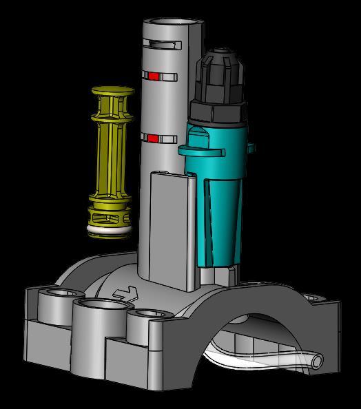
7 2. Description of pump The POOLeasy ph is characterised by its capacity to measure the ph value (between ph 0 and 14) thanks to its sensor placed in a filtration circuit that analyses your pool's water. As a function of the value measured, the POOLeasy PH injects, using its dosing pump, the quantity of reagent necessary to maintain pool water balance. The POOLeasy PH operates in acid (ph-) or alkali (ph+) dosing mode, depending on its configuration. 2.1 Description of parts The complete list of accessories delivered with the equipment is given below. All the parts will be necessary for the correct operation of your unit. D A1 A2 P J B E F I Q M G H N O C K L A1 : ph4 / ph7 calibration solutions (ph kit) A2 : 475mV calibration solution (redox kit) B : Probe holder C : Guide collar D : Clip E : Foot strainer F : Bit G : Probe s o-ring (x2) H : Probe holder s o-ring I : 4x6 PVC tube (4m) J : ph or redox probe K : Probe holder s screw (x4) L : Probe holder s nut (x4) M : Wall mounting screw (x2) N : Wall mounting plug (x2) O : Spacers for Ø63 pipe (x4) P : Spacer for long probe (120mm.) Q : Water direction flux arrow 4

 or 4 ( ) allows the modification of")


8 2.2 Description of buttons: Long press on the MENU button gives access to the installation configuration and short press on the ESC button allows user to exit current menu SET button pressed together with buttons 3 ( ) or 4 ( ) allows the modification of the setpoint value The button allows an increase in the numerical value or scrolling the list of selections The button allows a decrease in the numerical value or scrolling the list of selections CAL and OK buttons, CAL allows the user to enter the automatically-guided calibration phase and OK allows the user to validate the value changes or validate a selection in a menu 5
9 3. Alarms and displayed symbols Message Meaning Action / and \ alternatives The pump is in the process of dosing Dosing is underway but the pump is paused. The pause lasts 5 minutes maximum. CALIBRATION ERR. Calibration not possible - Check state of calibration solution - Clean the sensor - Replace the sensor TANK EMPTY The reagent tank is empty LOW MEASUREMENT ph mode: Measured ph < ph 5 REDOX mode: measurement < 100 mv HIGH MEASUREMENT ph mode: Measured ph > ph 9 REDOX mode: measurement > 900 mv Check pool water parameters TAC > 100 mg/l Check pool water parameters TAC > 100 mg/l FILTR. DISABLED OVERDOSING ALARM The filtration pump is not operating. The POOLeasy unit is therefore paused. The POOLeasy unit has dosed more than the threshold defined in the settings. Refer to Section to disable filtration pump input if you do not want the POOLeasy unit to pause when the filtration pump stops. Refer to Section Installation and recommendations 4.1 Recommendations It is essential that the pump be installed far from a source of heat, in a dry place with a maximum ambient temperature of 40 C. Comply with the country's applicable standards with regard to electrical installations. 6

. This injector sensor holder is the support for the measurement electrode and injection valve.")
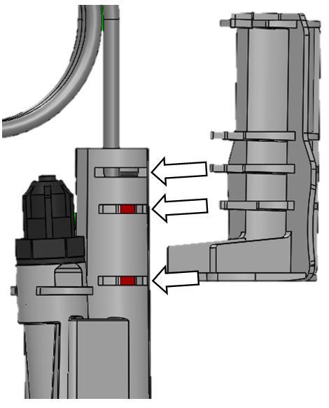
10 4.2 Principle of hydraulic and electrical installation Case of a POOLeasy ph connected to a permanent power supply and filtration detection with a salt chlorinator cell. i Fig. 3 Description of callouts on Figure 3 A- POOLeasy ph B- 2-in-1 sensor holder placed on the main pipe prior to any salt chlorinator cell (H) or after all pool accessories (heating, etc.). This injector sensor holder is the support for the measurement electrode and injection valve. C- Treatment reagent tank D- Electrical cabinet for control of pool circulation pump E- Pool water circulation pump. F- Pool G- Pool filter H- Salt chlorinator cell I- Electrical cable connecting the instrument to the electrical box 7
.")
11 4.2.2 Case of a POOLeasy ph and Redox connected to a permanent power supply and filtration detection with a salt chlorinator cell. J i Fig. 4 Description of callouts in Figure 4 A- POOLeasy ph B- 2-in-1 sensor holder placed on the main pipe after all pool accessories (heating, etc.). The guide collars B for the ph unit and H for the Redox unit shall be separated by 1 cm at most allowing the two injection catheters to join at the exit of the H sensor holder. This injector sensor holder is the support for the measurement electrode and injection valve. C- Treatment reagent tank D- Electrical cabinet for control of pool circulation pump E- Pool water circulation pump. F- Pool G- Pool filter H- 2-in-1 sensor holder for the injection of disinfectant and support of the Redox sensor I- Electrical cable connecting the instrument to the electrical box J- POOLeasy Rx Caution: Under no circumstances should "i" be connected in parallel on the filtration pump power-supply terminals "E" in the electrical box "D" The 2-in-1 sensor holder "B" or "H" may have a maximum inclination of +/- 45 with respect to the vertical axis For optimal working lifetime of your peristaltic tube, it is preferable not to exceed a pressure of 1 bar and under no circumstances to exceed a pressure of 1.5 bar. The ph sensor must be placed in front of the electrolytic salt cell and behind any other equipment. 8


 Leave the sensor submerged in tap")


12 4.3 Unit installation STEP 1: Installation of the fixing bracket Place the bracket on the area it should be fixed to Mark the holes and drill to the diameter indicated on the plugs Secure the bracket Slide the pump into the bracket Fig. 4 STEP 2: Prepare the sensor for startup 1) Remove the sensor's protective cap and keep it to reuse it for the winter shutdown period 2) Leave the sensor submerged in tap water for at least 20 minutes, before proceeding with the calibration. We therefore recommend that you start your installation with this step. STEP 3 : Drill a hole in the pipe using tool F F POOLeasy ph + POOLeasy RX 9


13 Min 15 Min 15 STEP 4 : Probe holder preparation 4.1. Remove the cap & storage Mount the o-ring (H) under the probe holder (B) 10


14 STEP 5 : Place the probe holder (B) by inserting the injection tube in the direction of the waterflow Q 11


15 STEP 6 : Securization on the pipe 1) Ø50 pipe K C L 2) Ø63 pipe K C L O 12


16 Vertical : 13
 detection plug, in the electrical box D present on")


17 STEP 7: Electrical circuit A D i 1. Connect the cable i (without filtration) detection plug, in the electrical box D present on your pool. This cable must be connected to an auxiliary contact of the filtration starter contact. The voltage will be 230V on the cable terminals when the filtration pump is on. In this way, the POOLeasy unit will be authorised to dose. 2. Connect the power-supply cable equipped with its plug, in a domestic power-supply socket. It is preferable that the 230VAC supply originate from your pool's electrical box D, just after the general circuitbreaker. STEP 8: Connect the sensor to the corresponding terminal on the instrument Plug the plug into the bayonet socket Rotate the plug ¼ turn to close the connection 14

 Caution before soaking the sensor in the ph 4 solution, rinse well using clean water RINCE PROBE, PUT IN PH 4, MOVE IR AROUND STOP TOUCHING & LET INSIDE ph 7.")
18 STEP 9 a: Calibration of the ph sensor - Remove the sensor from its soaking water indicated in Section 4.3, Step 2, and remove any excess water. Hold down the CAL/OK button for 5 SECONDS. Tip PRESS THE ESC KEY AT ANY TIME TO EXIT THE CALIBRATION PROCEDURE PLACE THE SENSOR IN THE ph7 SOLUTION, SHAKE, LEAVE INSIDE WITHOUT TOUCHING ph 8.5 PRESS OK CALIBRATING ph 7 ph 7.25 (-90s) Caution before soaking the sensor in the ph 4 solution, rinse well using clean water RINCE PROBE, PUT IN PH 4, MOVE IR AROUND STOP TOUCHING & LET INSIDE ph 7.0 PRESS OK CALIBRATION ph 4 ph 7.25 (-90s) QUALITY 100% ph 4.0 PRESS OK After pressing OK, the unit continues operating normally Tip PRESS THE ESC KEY AT ANY TIME TO EXIT THE CALIBRATION PROCEDURE 15

19 STEP 9 b: Calibration of the Redox sensor - Remove the sensor from its soaking water indicated in Section 4.3, Step 2, and remove any excess water. Hold down the CAL/OK button for 5 SECONDS. Tip PRESS THE ESC KEY AT ANY TIME TO EXIT THE CALIBRATION PROCEDURE PLACE THE SENSOR IN THE 475 mv SOLUTION, SHAKE, LEAVE INSIDE WITHOUT TOUCHING ph 8.5 PRESS OK CALIBRATION mv ph (-90s) QUALITY 100% 475 ph PRESS OK After pressing OK, the unit continues operating normally Tip PRESS THE ESC KEY AT ANY TIME TO EXIT THE CALIBRATION PROCEDURE 16


20 STEP 10 : Installation of the short probe (80mm.) 1 2 G J 3 17


 If you would like to obtain a ph of 7.")
21 STEP 11: Hydraulic circuit Cut Tube J to connect the foot filter B to the pump's left inlet and the sensor holder D on the pump's right inlet. Position the foot filter B at the bottom of the trough. Tube J A nut Connector Valve : The hydraulic tube is placed in the same way on the strainer and the pump. 1: Slide the tube through the nut 2: Push the tube down to the bottom of the conical connector 3: Hand tighten the nut onto the connector STEP 12: Installation complete At this stage, the POOLeasy ph or Redox is ready for use without any further adjustments in most cases. Default ph values - Setpoint at ph Dosing of acid reagent to bring the ph down Default Redox values - Setpoint at 700 mv (corresponding to about 1 mg/l at ph 7.4) If you would like to obtain a ph of 7.4 and you are dosing with acid, your unit is ready for use without further preparation. Otherwise, please refer to the following sections to adjust the advanced parameters as a function of your needs. 18
22 5. ADVANCED UNIT SETTINGS 5.1 Setpoint adjustment HOLD DOWN THE SET BUTTON and using the or buttons ADJUST THE VALUE SETPOINT VALUE ph 7.4 WHEN THE SET BUTTON IS RELEASED, THE VALUE WILL BE MEMORIZED 5.2 SETTINGS MENU HOLD DOWN THE MENU/ESC BUTTON for 5 seconds to enter the menu Once inside the menu, use the and buttons to scroll between the different choices, and the CAL/OK button to validate and move to the next menu. At any time, press the MENU/ESC button to exit the menu. LANGUAGE FRENCH Language selection MEASUREMENT TYPE ph Choice of measurement type between ph and REDOX Refer to Section 5.1 for ph mode Refer to Section 5.2 for REDOX mode 19
23 5.2.1 POOLeasy settings in ph mode To set your POOLeasy in ph mode, refer to the previous section (5.0) MEASUREMENT TYPE ph DOSING MODE ACID (ph-) Choice of reagent for dosing between acid (ph-) and alkaline (ph+) PUMP FLOWRATE 1.5 L/h Flowrate setting for pump on the unit (1.5 or 3 L/h) Factory setting PUMP ACT. TIME 20 s/0.1ph Setting of pump activation time in steps of ph 0.1, for correction OVERDOSING ALARM 0.5 L/4 Hrs Setting of overdosing alarm: refer to Section No. of calib. points 2 Setting of number of calibration points (1 or 2). The single calibration point is at ph 7. MEASUREMENT ADJUST 0.00 ph Adjustment of the displayed value by + or ph CAUTION: improper use of this parameter may result in erroneous dosing. PUMP FLT INPUT ON Allows the enabling/disabling of the 230V input corresponding to the enabling of the filtration pump. It is the input that corresponds to cable "i" defined in Step 13 of the installation procedure. FACTORY SETTINGS NO Allows unit reinitialization. By selecting YES, a confirmation will follow. Return to language selection menu. Press MENU/ESC to exit the menu. 20
24 5.2.2 POOLeasy settings in REDOX mode To set your POOLeasy in REDOX mode, refer to Section (5.0) MEASUREMENT TYPE REDOX PUMP FLOWRATE 1.5 L/h Flowrate setting for pump on the unit (1.5 or 3 L/h) PUMP ACT. TIME 6 s/mv Setting of pump activation time in steps of 1 mv, for correction OVERDOSING ALARM 0.5 L/4 Hrs Setting of overdosing alarm: refer to Section MEASUREMENT ADJUST 0 mv Adjustment of the displayed value by + or 30 mv. CAUTION: improper use of this parameter may result in erroneous dosing. PUMP FLT INPUT ON Allows the enabling/disabling of the 230V input corresponding to the enabling of the filtration pump. It is the input that corresponds to cable "i" defined in Step 13 of the installation procedure. ACTIVATION TIME 12 min Adjustment of the measurement stabilization period (in minutes) after switching the unit on. Dosing will only start after this waiting period. FACTORY SETTINGS NO Allows unit reset. By selecting YES, a confirmation will follow. Return to language selection menu. Press MENU/ESC to exit the menu. 21
25 5.2.3 Guide for setting activation time for the ph or Redox pumps Water volume M3 Pump Acti Time S / 0.1 ph Pump Acti Time S / mv From 1 to From 11 to From 21 to From 41 to From 91 to From 130 to The values given in this table are indicative and should be adjusted as a function of the configuration and use of your pool Overdose alarm settings The pump blocks its dosing and displays an alarm message when it has dosed more than the volume indicated in the alarm menu for 4 consecutive hours. This alarm allows dynamic monitoring of any potential overdosing. HOLD DOWN THE MENU/ESC KEY for 5 seconds Press CAL/OK several times (4 times) until you enter the OVERDOSE ALARM menu OVERDOSING ALARM 0.05 L/4 Hrs Adjusting the overdose alarm: above the defined threshold, the pump enters a state of alarm and requires that the CAL/OK button be pressed to start again. To disable the alarm, adjust the threshold to 0 L/h (OFF). Average information: 1 L of acid brings ph down by 0.3 in a pool of 100 M3 1 L of chlorine adds 1 ppm in a pool of 100 m3 If the threshold is set to 0.00 L/h (OFF), the alarm is disabled. Press MENU/ESC to exit. ALARM DISABLED 48h Possibility to disable the alarm for 24h or 48h to simplify startup, for example. OFF to enable the alarm without period. 22

26 When the unit is in an alarm state, the following screen is displayed ***** OVERDOSING ALARM Simply press CAL/OK to cancel the alarm. 5.3 POOLeasy standby mode To place the POOLeasy in standby mode, press the and keys simultaneously for 5 seconds. To exit standby mode, repeat the same operation. 5.4 POOLeasy priming 1 Place the POOLeasy in standby mode by pressing the and keys simultaneously for 5 seconds. 2 Press the MENU/ESC and CAL/OK keys simultaneously for the desired time to prime the pump. 3 Exit standby mode by again pressing and simultaneously. 5.5 Principle of operation The POOLeasy adjusts its dosing proportionally to demand. This means that it will dose less if the displayed measurement is close to the setpoint (desired ph). To dose less, the POOLeasy inserts increasingly long pauses between increasingly short operating times. This is why the unit often has the pump stopped when the displayed value is not the same as the setpoint value. This is normal and the unit displays the hourglass icon Adjusting ph slowly preserves the natural quality of your water. After 30 minutes without pressing any keys, the backlighting is switched off to save energy. Briefly pressing SET or CAL re-activates this. 6. Electrical terminals 6.1 Terminal markings 1 and 2 Filtration pump detection (230Vac) 3 Not connected 4 and 5 Pre-powered 230Vac outlet for auxiliary pump or solenoid valve 6 Not connected 7 and 8 Alarm output, dry contact without voltage 9 Not connected 10 and 11 Dry-contact level detector input 23


27 7. Maintenance 7.1 Replacement of the peristaltic tube Fig Maintenance of chlorine injection valve. Clean the injector tube from chlorine deposit with acid water or replace PVC tube. 24
28 7.3 Electrode maintenance General remarks Over time, in addition to normal electrode wear, depending on usage and degree of hardness of water, the measurement will deteriorate. A thin layer of limescale, together with other elements present in the pool water, will be deposited on the sensitive elements of the sensor. To mitigate this problem, it is recommended to use the AYACSOLNET02 ph or redox electrode cleaning solution and follow the procedure indicated on the flacon. 25


29 7.3.2 Installation of a long probe (120mm.) 1 2 P J G 3 26
30 7.4 POOLeasy winter shutdown It is important to know that for the winter shutdown of your unit, it is the peristaltic tube that needs protecting. It is then recommended to pump clean water to rinse the peristaltic tube 7.5 Sensor winter shutdown For the winter shutdown, the sensor must be removed from the installation and stored in nonfreezing conditions. Clean the sensor extremity using AYACSOLNET02 cleaning solution. This allows the removal of any deposits formed during its use in pool water. The sensor must be filled to 1/3 with AYACSOLSTK01 storage solution and the protective cap placed on the sensor's extremity. This assembly must be stored away from freezing conditions at ambient temperature. 7.6 Recommended and unrecommended chemicals - It is recommended to use sulfuric acid, which is 100% compatible with the Santoprene tube. - It is not recommended to use hydrochloric acid which can reduce the peristaltic tube's lifetime to a few weeks and oxidise the pump's s metallic parts. In this case, the warranty is voided. 27


31 8. Spare parts list Fig. 14 Code Description of parts 1 AYAC MET motor, 20 RPM, type B 2 AYAC Peristaltic tube, type B 3 AYAC Roller holder, type B 4/5/6 AYFA0009 Bearing kit/b cover/screw 7 AYAC08AC01 ph electrode AYAC08BC01 Rx electrode 8 AYFA00011 Complete 2-in-1 sensor holder 9 AYFA00004 Sensor-holder cap 10 AYAC Strainer 11 AYAC Clip 12 AYAC Crystal PVC tube, 4x6 AYAC02C001 ph4 calibration solution 13 AYAC02C002 ph7 calibration solution AYAC02C mv Redox solution 14 AYFA00010 Injector / AYACSOLSTK01 ph-rx sensor storage solution, 100mL / AYACSOLNET02 ph-rx sensor cleaning solution, 250mL / AYAC BNC + cable / AYAC Securing bracket / AYAC Fuse, T500mA 5x Fig
32 NOTES AVADY POOL - 9, Chaussée Jules César, Bâtiment 4 Hall OSNY France Tel : +33 (0) Fax : +33 (0) contact@avadypool.com Web : Installation and operating instructions are included with the product when purchased new. They can also be found on our website.
"DAD-P" PERISTALTIC PUMP
 "DAD-P" PERISTALTIC PUMP OPERATING INSTRUCTIONS AND MAINTENANCE ENGLISH 11 INDEX 1.0 - HINTS AND WARNING pag. 14 1.1 - WARNING 14 1.2 - SHIPPING AND TRANSPORTING THE PUMP 14 1.3 - PROPER USE OF THE PUMP
US Water ph Booster-Reducer Injection System
 US Water ph Booster-Reducer Injection System 410-PHBOOST 410-PHREDUCER US Water Systems, Inc. 1209 Country Club Road Indianapolis, IN 46234 1-800-608-8792 info@uswatersystems.com www.uswatersystems.com
easyflow-vs Variable Speed Peristaltic Dosing Pump
 easyflow-vs Variable Speed Peristaltic Dosing Pump TPS Pty Ltd ABN 30 009 773 371 4 Jamberoo Street Springwood, Brisbane, Australia, 4127 Phone : (07) 32 900 400 International : 61 7 32 900 400 Fax : (07)
testo 206 ph/ Temperature Measuring Instrument Bedienungsanleitung Instruction Manual
 testo 206 ph/ Temperature Measuring Instrument Bedienungsanleitung de Instruction Manual en 18 General Information General Information Please read this document through carefully and familiarise yourself
US Water ORP Booster Injection System
 US Water ORP Booster Injection System US Water Systems, Inc. 1209 Country Club Road Indianapolis, IN 46234 1-800-608-8792 info@uswatersystems.com www.uswatersystems.com REVISION 1.1, 9-14-15 Table of Contents
INSTALLATION, SERVICE AND MAINTENANCE INSTRUCTIONS Y-FILTER 83700
 INSTALLATION, SERVICE AND MAINTENANCE INSTRUCTIONS Y-FILTER 83700 11.106.32.0001 INOXPA, S.A. c/telers, 54 Aptdo. 174 E-17820 Banyoles Girona (Spain) Tel. : (34) 972-57 52 00 Fax. : (34) 972-57 55 02 email:
INSTALLATION, SERVICE AND MAINTENANCE INSTRUCTIONS Y-FILTER 83700
 INSTALLATION, SERVICE AND MAINTENANCE INSTRUCTIONS Y-FILTER 83700 11.106.32.0001 INOXPA, S.A. c/telers, 54 Aptdo. 174 E-17820 Banyoles Girona (Spain) Tel. : (34) 972-57 52 00 Fax. : (34) 972-57 55 02 email:
1. GENERAL SAFETY INSTRUCTIONS 2. GENERAL SAFETY RULES GENERAL OBSERVATIONS.
 ENGLISH IMPORTANT: The manual you are reading contains fundamental information regarding the safety measures to be adopted when installing and starting up. It is therefore of utmost importance that both
Visit us at
 Instruction Manual testo 206 ph/ Temperature Measuring Instrument 99 Washington Street Melrose, MA 02176 Phone 781-665-1400 Toll Free 1-800-517-8431 Visit us at www.testequipmentdepot.com 2 General Information
Flue Gas Analyzer IMR 1100F
 Flue Gas Analyzer IMR Environmental Equipment. Inc. 3634 Central Ave. St. Petersburg Florida 33711 Tel: 727-328-2818 Fax 727-328-2826 info@imrusa.com www.imrusa.com User Manual INTRODUCTION 3 SAFETY INSTRUCTIONS
Visit us at
 Instruction Manual testo 205 ph/ Temperature Measuring Instrument 99 Washington Street Melrose, MA 02176 Phone 781-665-1400 Toll Free 1-800-517-8431 Visit us at www.testequipmentdepot.com 2 General Information
ECONOMISER SERIES E2T USER MANUAL
 TURBO S.R.L. Electronic Control Systems for Dust Collectors e-mail: info@turbocontrols.it web: www.turbocontrols.it TEL. ++39 (0)362 574024 FAX ++39 (0)362 574092 ECONOMISER SERIES E2T USER MANUAL 24/06/2014
WARRANTY...1 NOTICE INTRODUCTION USE...8
 Contents WARRANTY...1 NOTICE...2 1 INTRODUCTION...3 1.1 ABOUT...3 1.2 UNPACKING...3 1.3 INCLUDED ITEMS...4 1.4 COMPONENTS...4 2 USE...8 2.1 POWER ON...8 2.2 SETTINGS...9 2.2.1 Setup Wizard...9 2.2.2 Set
Reverse Polarity MANUAL. Surechlor S3500
 Reverse Polarity MANUAL Surechlor S00 Surechlor S00 MANUAL Contents Installation Cell Power pack Off Peak Installation Connecting the Pool Pump Installation Layout Operation Chlorine Control LED Chlorine
PC60 Premium Multi-Parameter Tester (ph/ec/tds/salinity/temp.) Instruction Manual. APERA INSTRUMENTS, LLC V6.4
 Instruction Manual. APERA INSTRUMENTS, LLC V6.4") PC60 Premium Multi-Parameter Tester (ph/ec/tds/salinity/temp.) Instruction Manual APERA INSTRUMENTS, LLC www.aperainst.com V6.4 Thank you for purchasing Apera Instruments PC60 Premium Multi-Parameter Tester.
PC60 Premium Multi-Parameter Tester (ph/ec/tds/salinity/temp.) Instruction Manual APERA INSTRUMENTS, LLC www.aperainst.com V6.4 Thank you for purchasing Apera Instruments PC60 Premium Multi-Parameter Tester.
LABORATORY ZERO AIR GENERATOR MODEL N-GC1500 USER S MANUAL
 LABORATORY ZERO AIR GENERATOR MODEL N-GC1500 USER S MANUAL Content 1. Introduction...2 2. Important safety instruction...3 3. System component...4 4. Engineering design overview...5 5. Installation...6
c-go 24V/6A 24V/8A 24V/12A
 c-go 24V/6A 24V/8A 24V/12A Battery charger GB Instruction manual 1 Index 1. Product description... 2 2. Safety advices... 3 3. Quick start guide... 4 4. Operation... 4 5. Problem solving... 6 6. Specifications...
Switching DC Power Supply
 99 Washington Street Melrose, MA 02176 Phone 781-665-1400 Toll Free 1-800-517-8431 Visit us at www.testequipmentdepot.com Model 1693, 1694 Switching DC Power Supply INSTRUCTION MANUAL 1 Safety Summary
ENGLISH SAFETY INSTRUCTIONS. Recommendations for safe operation. Operator safety. General warnings
 Safety and use instructions LifeSpeed iq TM - 3-phase chargers ENGLISH SAFETY INSTRUCTIONS GOALS OF THIS MANUAL This manual is aimed at any authorized personnel wanting to use a 3-phase LifeSpeed iq TM
Instruction Manual & Warranty Card
 Instruction Manual & Warranty Card Pool Builder: Pool Owner: Hand to Pool Owner. Mail your Zodiac Warranty Registration today! MASTERING THE ELEMENTS Renowned worldwide for the quality and reliability
Advanced Calibration Designs, Inc. Release II
 Advanced Calibration Designs, Inc. Release II www.goacd.com WARNING: This instrument generates test gas for toxic gas detectors. The instruction manual should be read and understood prior to operation
AIR FILTER MODEL NO: AF1000 OPERATION & MAINTENANCE INSTRUCTIONS PART NO:
 AIR FILTER MODEL NO: AF1000 PART NO: 6471160 OPERATION & MAINTENANCE INSTRUCTIONS 1208 INTRODUCTION Thank you for purchasing this Clarke Air Filter. Before you try to use this product, read this manual
Installation manual ACO Mains operated drain doser (MODD) for Grease Traps
 for Grease Traps") Installation manual ACO Mains operated drain doser (MODD) for Grease Traps Installation manual Installation manual - ACO Mains operated drain doser (MODD) for Grease Traps Safety Notes IMPORTANT: Please
Installation manual ACO Mains operated drain doser (MODD) for Grease Traps Installation manual Installation manual - ACO Mains operated drain doser (MODD) for Grease Traps Safety Notes IMPORTANT: Please
SERVICE MANUAL. STARTER Portable Meter ST300 ST300C ST300D ST400D. Ohaus Corporation, 7 Campus Drive, Suite 310, Parsippany, NJ (973)
") SERVICE MANUAL STARTER Portable Meter ST300 ST300C ST300D ST400D Ohaus Corporation, 7 Campus Drive, Suite 310, Parsippany, NJ 07054 (973) 377-9000 SERVICE MANUAL STARTER Portable Meter ST300 ST300C ST300D
SERVICE MANUAL STARTER Portable Meter ST300 ST300C ST300D ST400D Ohaus Corporation, 7 Campus Drive, Suite 310, Parsippany, NJ 07054 (973) 377-9000 SERVICE MANUAL STARTER Portable Meter ST300 ST300C ST300D
Pro Booster 802Li. Please read and fully understand the instructions in this manual before operation. Keep this manual safe for future reference.
 Please dispose of packaging for the product in a responsible manner. It is suitable for recycling. Help to protect the environment, take the packaging to the local amenity tip and place into the appropriate
0.7 m 3 /h - 3 GPM D 07 RE 125 D 07 RE 5. owner s manual
 0.7 m 3 /h - 3 GPM D 07 RE 125 D 07 RE 5 owner s manual GB You have just become the owner of one of the latest in the line of DOSATRON proportional dosing pumps and we congratulate you on your choice.
VSP SERIES Installation, Operation and Maintenance Manual
 VSP SERIES Installation, Operation and Maintenance Manual VARIABLE SPEED PERISTALTIC METERING PUMPS VSP-12 and VSP-20 Models READ ALL WARNINGS CAREFULLY BEFORE INSTALLING PUMP PUMP DATA/SPECIFICATIONS
Fuel Level FL1. FL1 - User s manual. Rev Revision#2.0, 28/11/2014 For firmware version 1.2
 Fuel Level FL1 Revision#2.0, 28/11/2014 For firmware version 1.2 FL1 - User s manual Page intentionally left blank SECTIONS MECHANICAL INSTALLATION ELECTRICAL INSTALLATION OPERATING INSTRUCTIONS INSTRUMENT
Extended Battery Cabinet for Nfinity
 POWER PROTECTION Extended Battery Cabinet for Nfinity USER MANUAL TABLE OF CONTENTS IMPORTANT SAFETY INSTRUCTIONS................................... 1 ELECTROMAGNETIC COMPATIBILITY.......................................
SUBMERSIBLE WATER PUMP
 SUBMERSIBLE WATER PUMP MODEL NO: CSV1A, CSV2A PART NO: 7230582, 7230602 OPERATION & MAINTENANCE INSTRUCTIONS ORIGINAL INSTRUCTIONS 05/14 iss 4 INTRODUCTION Thank you for purchasing this CLARKE Submersible
USE AND INSTALLATION HANDBOOK
 Date : 10/02/14 Rev. 01 PR.T : FG006172 USE AND INSTALLATION HANDBOOK DUPLEX-UP CONTROL PANEL FOR 2 ELECTRIC PUMPS WITH CURRENT CONTROL. DUPLEX-UP Via Enrico Fermi 8-35020 Polverara PD Tel.049/9772407
Chargestar P24 / P32 Battery Charger Startmaster P300 Starter / Charger
 Please dispose of packaging for the product in a responsible manner. It is suitable for recycling. Help to protect the environment, take the packaging to the local amenity tip and place into the appropriate
INSTALLATION, SERVICE AND MAINTENANCE INSTRUCTIONS RIGHT ANGLE FILTER Original Manual EN (0) 2019/02
 2019/02") INSTALLATION, SERVICE AND MAINTENANCE INSTRUCTIONS RIGHT ANGLE FILTER 82700 11.103.32.0001 Original Manual 11.103.30.02EN (0) 2019/02 EC Declaration of Conformity 11.103.30.03ES 11.103.30.03EN (0) 2019/01
INSTALLATION, SERVICE AND MAINTENANCE INSTRUCTIONS RIGHT ANGLE FILTER 82700 11.103.32.0001 Original Manual 11.103.30.02EN (0) 2019/02 EC Declaration of Conformity 11.103.30.03ES 11.103.30.03EN (0) 2019/01
MARTINDALE MARTINDALE IN2001/IN2003 INSULATION & CONTINUITY TESTERS INSTRUCTION MANUAL IN2001/IN2003 INSULATION & CONTINUITY TESTERS
 MARTINDALE ELECTRIC Martindale Electric Company LTD Metrohm House Penfold Trading Estate Imperial Way Watford Herts WD24 4YY T: 01923 441717 F: 01923 446900 Email: sales@martindale-electric.co.uk web:
BNT 85 /185 Valve Operation Manual
 BNT 85 /185 Valve Operation Manual Note: 1. Read all instructions carefully before operation. 2. Avoid pinched o-rings during installation by applying (provided with install kit) NSF certified lubricant
Bante220 Portable ph Meter Instruction Manual
 Bante220 Portable ph Meter Instruction Manual BANTE INSTRUMENTS CO., LTD Bante220 Portable ph Meter 1 Introduction Thank you for selecting the Bante220 portable ph meter. This manual provides a step-by-step
USER MANUAL FOR AUTOMATIC A/C CHARGING STATIONS
 USER MANUAL FOR AUTOMATIC A/C CHARGING STATIONS Nano Nano 2 Nano Hybrid ITECH Creative Technology INDEX 1 INTRODUCTION... 2 1.1 Safety instructions... 2 2 EQUIPMENT... 2 3 USE... 4 3.1 Control panel...
Atlas ESR and ESR + Equivalent Series Resistance and Capacitance Meter. Model ESR60/ESR70. Designed and manufactured with pride in the UK.
 GB60/70-9 Atlas ESR and ESR + Equivalent Series Resistance and Capacitance Meter Model ESR60/ESR70 Designed and manufactured with pride in the UK User Guide Peak Electronic Design Limited 2004/2016 In
C3 Operating Instructions
 Version 3.1 Stand 09.2014 Robert Bosch (Australia) Pty. Ltd. 1555 Centre Road Clayton, Victoria 3168 C3 Operating Instructions For further information please contact Bosch at: Australia 1300 30 70 40 www.boschautoparts.com.au
Installation and operating instructions. Solar charge controller MPPT 10 A / 20 A Z Z
 Installation and operating instructions Solar charge controller MPPT 10 A / 20 A EN 1 Contents 1. About these instructions... 3 1.1 Applicability... 3 1.2 Users... 3 1.3 Description of symbols... 3 2.
SPEEDRIVE INSTRUCTIONS MANUAL
 EN SPEEDRIVE INSTRUCTIONS MANUAL Safety warning. The following symbols shown beside a paragraph represent danger warnings associated to the failure to comply with the corresponding instructions. DANGER!
77014 / Automatic Users Manual. Carefully read this entire Instruction Manual before using this product
 77014 / 65041 Submersible Water Pumps Automatic Users Manual Carefully read this entire Instruction Manual before using this product Please read these operating instructions carefully and ensure they are
i n s t r u c t i o n m a n u a l
 i n s t r u c t i o n m a n u a l 8006 Six-Station AC Timer Residential/Light Commercial Independent Program Irrigation Controllers Installation, Programming and Operating Instructions Features Operates
Start UP Guide. Symmetra LX Tower Rack-Mount. UPS Models 200 V, 4-8 kva 208/240 V, 4-8 kva 220/230/240 V, 4-8 kva
 Start UP Guide Symmetra LX Tower Rack-Mount UPS Models 200 V, 4-8 kva 208/240 V, 4-8 kva 220/230/240 V, 4-8 kva 200 V, 4-16 kva 208/240 V, 4-16 kva 220/230/240 V, 4-16 kva Important Safety Messages SAVE
Manifold QF. Contents. Description. Installation & Setup Guide. Safety 3. Introduction 3. Installation Standards 4. Specifications 5.
 Contents Description Page Safety 3 Introduction 3 Installation Standards 4 Specifications 5 Materials 5 Overall System Configurations 6 Manifold Installation 7 Fixing Unit to Wall 7 Water Connection 8
FREQUENCY INVERTER INSTALLATION & USER GUIDE
 En FREQUENCY INVERTER INSTALLATION & USER GUIDE Thank you for purchasing our frequency inverter. Please read the manual carefully before installing or using it and keep it for future reference after installation.
Andatech SOBERPOINT 3. Wall Mounted Breathalyser USER S MANUAL
 Andatech SOBERPOINT 3 Wall Mounted Breathalyser USER S MANUAL Thank you for purchasing an Andatech Soberpoint 3 breathalyser. The Andatech Soberpoint 3 is a Fuel Sensor type coin- or buttonoperated breathalyser.
SELF PRIMING CHEMICAL SERVICE PUMPS
 SELF PRIMING CHEMICAL SERVICE PUMPS INSTALLATION AND OPERATING INSTRUCTIONS This Manual covers: SELF PRIMING MODEL RANGE J50ECX TO J250ECX STAINLESS STEEL*, and NON METALLIC SEAL PUMP MODEL: SERIAL NO:
Rescue Pac. Please read and fully understand the instructions in this manual before operation. Keep this manual safe for future reference
 Please dispose of Packaging for the product in a responsible manner. It is suitable for recycling. Help to protect the environment, take the packaging to the local amenity tip and place into the appropriate
Owners Manual: - Pumps
 Owners Manual: - Pumps GENERAL SAFETY RULES 1. The products mentioned in this manual are specially designed for the pre-filtering and re-circulation of water in swimming pools and spas. 2. They are designed
Agxcel GX12i Chemical Injection System
 Agxcel GX12i Chemical Injection System Table of Contents System Contents... 3 Specifications... 4 Safety Precautions and Tips... 5 Operations... 6 Installation... 7 Maintenance... 8-9 Troubleshooting...
MARTINDALE INSTRUCTIONS ELITE FUSE FINDER KIT ELECTRIC. Trusted by professionals. 4.4 Storage Conditions
 4.4 Storage Conditions The FD650/R and FD500/T or FD600/T should be kept in warm dry conditions away from direct sources of heat or sunlight, with the battery removed and in such a manner as to preserve
User Manual Solar Charge Controller 3KW
 User Manual Solar Charge Controller 3KW Version: 1.3 CONTENTS 1 ABOUT THIS MANUAL... 1 1.1 Purpose... 1 1.2 Scope... 1 1.3 SAFETY INSTRUCTIONS... 1 2 INTRODUCTION... 2 2.1 Features... 2 2.2 Product Overview...
EC Mini Controller. Installation and user guide. Simple, Robust, Reliable
 EC Mini Controller Installation and user guide Simple, Robust, Reliable Measures EC or CF or TDS Doses nutrients on-demand as they get used up Displays EC (or CF/TDS), Total Dose count (DCT) and Dose count
PolyStat Immersion Circulators
 PolyStat Immersion Circulators Manual P/N U00988 Rev. 06/09/08 Instruction and Operation Manual PolyStat Immersion Circulator Table of Contents Preface Safety Compliance... 2 Unpacking... 2 Warranty...
AC Irrigation and Propagation Controllers I Four Station, 5006-I and 5006-IP Six Station
 AC Irrigation and Propagation Controllers 5004-I Four Station, 5006-I and 5006-IP Six Station I N S T R U C T I O N M A N U A L Table of contents Introduction 1 1. Specifications 1 2. Controller Mounting
TRACER. POCKETESTER ä ORP CODE 1742
 TRACER POCKETESTER ä ORP CODE 1742 TRACER ORP POCKETESTER TM CODE 1742 Table of Contents Introduction... 4 Specifications... 4 Contents... 4 Parts & Accessories... 4 Meter Description Front Panel Description...
TYRECONTROL «PT» A-188
 TYRECONTROL «PT» A-188 User Manual (EN) 2 Introduction The TYRECONTROL «PT» allows you to : - Measure the air pressures - Adjust the air pressures (only to decrease) - Measure the temperatures on the surface
GLOBE FLOWCELL. Operating Manual. Rola-Chem Flowcell PN /01/2013 page: 1 of 8
 GLOBE FLOWCELL Operating Manual Rola-Chem Flowcell PN 550182 4/01/2013 page: 1 of 8 Table of Contents Section title Page 1.0 Safety Instructions 2 2.0 Description 2 3.0 Installation 3 4.0 Use of Manifold
Mod: KLD6-12/35XLAS-N
 12/2011 Mod: KLD6-12/35XLAS-N Production code: 1914070 INSTRUCTION MANUAL LOGIC LINE PLUS HOOD Reseller Stamp for Warranty Dear customer, Above all, thank you for choosing our product and we would like
CO95. Carbon Monoxide Detector INSTRUCTION MANUAL ENGLISH Fax: (503)
") CO95 Carbon Monoxide Detector INSTRUCTION MANUAL ENGLISH CO95 C ARBON MONOXIDE DETECTOR 1-800-547-5740 Fax: (503) 643-6322 www.ueitest.com Email: info@ueitest.com TABLE OF CONTENTS Introduction... 3 Safety...
CO95 Carbon Monoxide Detector INSTRUCTION MANUAL ENGLISH CO95 C ARBON MONOXIDE DETECTOR 1-800-547-5740 Fax: (503) 643-6322 www.ueitest.com Email: info@ueitest.com TABLE OF CONTENTS Introduction... 3 Safety...
Car Battery Charger Instructions for Use
 BATTERY CHARGER 12Volt 4Amp FOR INDOOR USE ONLY Power Details: Input: 230-240Vac; 50Hz; 52W Output: 12V DC; 2.8A Maximum Charge Rate: 4A RMS Read these instructions before operating this car battery charger
INSTALLATION AND OPERATING INSTRUCTIONS
 INSTALLATION AND OPERATING INSTRUCTIONS I INSTALLATION AND OPERATING INSTRUCTIONS Hurlcon Pumps CTX Series, E Series BX Series & FX Series Bolero ND Cleaner INSTALLATION AND OPERATING INSTRUCTIONS Melbourne:
SUBMERSIBLE DIRTY WATER PUMP
 FOR USE WITH A 110V SUPPLY ONLY SUBMERSIBLE DIRTY WATER PUMP MODEL NO: DWP210A PART NO: 7230102 OPERATION & MAINTENANCE INSTRUCTIONS LS0115 INTRODUCTION Thank you for purchasing this CLARKE Submersible
Container Fountain Kit with LED Light
 Container Fountain Kit with LED Light REMINDER CALL 1-888-755-6750 BEFORE RETURNING TO STORE. PACKAGE CONTENTS Questions, problems, missing parts? Before returning to your retailer, call our customer service
User Manual Digital Water Level Indicator for rain water storage tanks
 User Manual Digital Water Level Indicator for rain water storage tanks We congratulate you on the purchase of Digital Water Level measuring device. You have purchased a high-quality product built to the
9 VOLT ALKALINE. not included
 Aquauno Logica 0 ES 1 FR 9 9 VOLT ALKALINE not included 8 Table of contents Introduction... Features...5 Operating controls...6 Operating tips...7 Battery installation...8-9 Installation on faucet...10
Declaration of Conformity No. 33/2010
 tech -1- ST 430 user's manual Declaration of Conformity No. 33/2010 Hereby, we declare under sole responsibility that the ST-430 230V, 50Hz thermoregulator manufactured by TECH, ul. St. Batorego 14, 34-120
Dycon D2430 EN54-4 Fire Alarm Power Supply Series
 Dycon D2430 EN54-4 Fire Alarm Power Supply Series Technical Description Installation and Operating Manual Construction Product Regulation 0359-CPR-00434 Page 1 of 14 Contents 1. General... 3 1.1 Product
IN1001/IN1003 ANALOGUE INSULATION & CONTINUITY TESTERS INSTRUCTION MANUAL IN1001/IN1003 ANALOGUE INSULATION & CONTINUITY TESTERS INSTRUCTION MANUAL
 Martindale Electric Company LTD Metrohm House Penfold Trading Estate Imperial Way Watford Herts WD24 4YY T: 01923 441717 F: 01923 446900 Email: sales@martindale-electric.co.uk web: www.martindale-electric.co.uk
Instrucciones de instalación y funcionamiento Installation and operating instructions
 Wilo-ElectronicControl D Einbau- und Betriebsanleitung E Instrucciones de instalación y funcionamiento GB Installation and operating instructions I Istruzioni di montaggio, uso e manutenzione F Notice
TIC 300 PRO. Users Manual Mode d emploi Bedienungshandbuch Manual d uso Manual de uso. Non Contact AC Voltage Detector. High Energy Tic Tracer
 TIC 300 PRO High Energy Tic Tracer Non Contact AC Voltage Detector Users Manual Mode d emploi Bedienungshandbuch Manual d uso Manual de uso TIC 300 PRO High Energy Tic Tracer Non Contact AC Voltage Detector
PURE SINE WAVE DC TO AC POWER INVERTER
 PURE SINE WAVE DC TO AC POWER INVERTER 60S-12A / 60S-24A 60S-12E / 60S-24E 100S-12A / 100S-24A 100S-12E / 100S-24E 150S-12A / 150S-24A 150S-12E / 150S-24E Instruction manual SINE WAVE INVERTER Please read
MP V 8A Electronic Smart Charger. Instruction and Information Manual
 MP7428 12V 8A Electronic Smart Charger Instruction and Information Manual In order to ensure correct and safe usage of your battery charger, you should read these instructions carefully. Please retain
OWNER S OPERATING MANUAL
 OWNER S OPERATING MANUAL ARC 140 AMP WELDER TABLE OF CONTENTS Page Safety instructions 3-4 Inverter Arc Welder 5 Welder Information 5 Arc 140 AMP welder set up 6 Assembly instructions 6 Operation 7 Welding
12v / 24v Diesel Transfer Pump Kit
 Please dispose of packaging for the product in a responsible manner. It is suitable for recycling. Help to protect the environment, take the packaging to the local amenity tip and place into the appropriate
B-RAD Select USER MANUAL TABLE OF CONTENTS
 TABLE OF CONTENTS TABLE OF CONTENTS... 1 MANUAL REVISION HISTORY... 2 IMPORTANT SAFETY NOTICE... 3 1.0 General Information... 5 1.1 System Components... 5 1.2 Specifications... 5 1.2.1 Torque Ranges...
MULTI FUNCTION POWER PAK PLUS
 MULTI FUNCTION JUMP START UP TO V8 PETROL & DIESEL 600A PEAK CURRENT RECHARGE USB POWER TOOLS TABLETS LAPTOPS MOBILE PHONES RECHARGE DEVICES ON-SITE VEHICLE JUMP STARTER KP1404 ED2 (June 15) Table of Contents
UVR-Mi UV-air flow Cleaner - Recirculator
 UVR-Mi UV-air flow Cleaner - Recirculator Medical Biological Research & Technologies Operating Manual Certificate for versions: V.2AA V.2AB 2 Contents 1. Safety Precautions 2. General Information 3. Getting
Battery Charger User Manual
 BY VANAIR Battery Charger User Manual September 2012 User Manual Battery Charger 4-7- 18 amps (2013 01 29) Questions? Contact us! www.helitowcart.com tel: +1.418.561.4512 info@helitowcart.com fax: +1.418.836.4575
CO 3-WAY PNEUMATIC VALVE INSTRUCTION MANUAL 2080
 CO 3-WAY PNEUMATIC VALVE INSTRUCTION MANUAL 2080 STI S.r.l has taken every care in collecting and verifying the documentation contained in this Instruction Manual. The information herein contained are
RUTLAND HRDi CHARGE REGULATOR INSTALLATION AND OPERATION
 RUTLAND HRDi CHARGE REGULATOR INSTALLATION AND OPERATION Introduction Congratulations and thank you for purchasing Marlec s HRDi Charge Regulator. This is the latest technology for charge regulation of
Type MZ15. Operating Instructions. Bedienungsanleitung Manuel d utilisation
 Handheld calibration tool / Handheld cleaning tool Tragbares Kalibrierwerkzeug / Tragbares Reinigungswerkzeug Outil d'étalonnage portatif / Outil de nettoyage portatif Operating Instructions Bedienungsanleitung
The function of this Dynamic Active Probe has divided into three preferences on the screen main Menus:
 1.0 Introduction: This probe is designed to provide an additional help to automotive technicians in trouble shooting of electrical circuits problems in the car. Apart from using the normal multi tester,
Controller Specification Sheet
 Controller Specification Sheet MC9320AXXXBX Proportional Inhibitor Dosing, Conductivity Bleed Control, Redox Control of Oxidising Biocide and Secondary Biocide Dosing PULSAtrol Controllers are microprocessor
Operators Manual. Model 3370 Air Cooled Recirculator rev.8/98
 Operators Manual Model 3370 Air Cooled Recirculator 110-080 rev.8/98 Table of contents Section 1. General Information 1.1 Warranty 1.2 Unpacking Section 2. Product Information 2.1 Description 2.2 Specification
Operating instructions
 Operating instructions Digital tank contents indicator DTA 10 DTA 10 DTA 10 0 4.0 m fuel oil 0 3.5 m water Read instructions before using device! Observe all safety information! Keep instructions for future
User Manual Pocket Pro, Pro + ph
 User Manual Pocket Pro, Pro + ph DOC022.52.80394 1 Specifications Specification Dimensions (W x D x H) Enclosure rating Weight Specifications are subject to change without notice. Details 37 x 30 x 170
Printed: Doc-Nr: PUB / / 000 / 00
 ORIGINAL OPERATING INSTRUCTIONS Hilti HTE-P 33 dispenser It is essential that the operating instructions are read before the tool is operated for the first time. Always keep these operating instructions
BATTERY OPERATED DIGITAL MILLI-OHMMETER
 BATTERY OPERATED DIGITAL MILLI-OHMMETER C 1 P 1 P 2 C 2 MAX. DC20V MICROPROCESSOR CONTROLLED AC DC HOLD M A X M I N AUTO-HOLD Hz mv km ka ms DIGITAL MILLIOHM METER 2000 200.0 20.00 2000m Test Current Range
2-PHASE STEPPING MOTOR DRIVER FE Z5 DISPENSE
 2-PHASE STEPPING MOTOR DRIVER FE Z5 DISPENSE For Diaphragm Dosing Pumps FEM 1.02_.55 / FEM 1.09_.55 Controller board package, without pump: ID 160536 Operating and Installation Manual It is important to
F-4600 INLINE ULTRASONIC FLOW METER Installation and Operation Guide
 F-4600 INLINE ULTRASONIC FLOW METER Installation and Operation Guide 11451 Belcher Road South, Largo, FL 33773 USA Tel +1 (727) 447-6140 Fax +1 (727) 442-5699 1054-7 / 34405 www.onicon.com sales@onicon.com
SERVICE MANUAL STARTER 2100 Bench ph Meter STARTER 3100 Bench ph Meter STARTER 3100C Bench ph Meter
 99 Washington Street Melrose, MA 02176 Phone 781-665-1400 Toll Free 1-800-517-8431 Visit us at www.testequipmentdepot.com SERVICE MANUAL STARTER 2100 Bench ph Meter STARTER 3100 Bench ph Meter STARTER
GL1200T Cut & Seal. (GL1200 Seal only)
") GL INSTRUMENTS & Operating Instructions Safe Seal Cut & Seal Welder for Filter Sacks GL1200T Cut & Seal (GL1200 Seal only) For industrial use only Important Safety & Operating Instructions Please read
GL INSTRUMENTS & Operating Instructions Safe Seal Cut & Seal Welder for Filter Sacks GL1200T Cut & Seal (GL1200 Seal only) For industrial use only Important Safety & Operating Instructions Please read
World Leaders in Diesel Fuel Injection Test Equipment. HM1000. Microdiesel Clean Cabinet. Installation and Operation Manual
 World Leaders in Diesel Fuel Injection Test Equipment. HM1000 Microdiesel Clean Cabinet Installation and Operation Manual Ref. No. HL022 (EN), Issue 1 HARTRIDGE LIMITED HM1000 MICRODIESEL CLEAN CABINET
Atlas ESR. User Guide. Capacitance and Equivalent Series Resistance Meter. Model ESR60 (Enhanced)
") Atlas ESR Capacitance and Equivalent Series Resistance Meter Model ESR60 (Enhanced) User Guide Peak Electronic Design Limited 2004/2008 In the interests of development, information in this guide is subject
Atlas ESR Capacitance and Equivalent Series Resistance Meter Model ESR60 (Enhanced) User Guide Peak Electronic Design Limited 2004/2008 In the interests of development, information in this guide is subject
SUBMERSIBLE WATER PUMP
 SUBMERSIBLE WATER PUMP MODEL NO: CSV1A, CSV2A PART NO: 7230582, 7230602 OPERATION & MAINTENANCE INSTRUCTIONS 0608 INTRODUCTION Thank you for purchasing this CLARKE Submersible Water Pump. This pump is
DOCUMENT TYPE = FITTING INSTRUCTIONS ORIGINAL LANGUAGE = ENGLISH. Maximum door weight = 40kg per leaf total system 80kg
 Evolve SIM Kit DOCUMENT TYPE = FITTING INSTRUCTIONS ORIGINAL LANGUAGE = ENGLISH 80kg Maximum door weight = 40kg per leaf total system 80kg Maximum door width 2 x 2mtr Track = 675-1058mm (Up to 2035 mm
Valor 1000W Series Instruction Manual. Serie Valor 1000W Manual de Instrucciones. Série Valor 1000W Guide de I utilisateur
 Valor 1000W Series Instruction Manual Serie Valor 1000W Manual de Instrucciones Série Valor 1000W Guide de I utilisateur Serie Valor 1000W Bedienungsanleitung Serie Valor 1000W Manuale d instruzioni OHAUS
Operating Instructions for Oval Wheel Flowmeter. Model: DOC
 Operating Instructions for Oval Wheel Flowmeter Model: DOC We don t accept warranty and liability claims neither upon this publication nor in case of improper treatment of the described products. The document