TYRECONTROL «PT» A-188
|
|
|
- Sharlene Moody
- 5 years ago
- Views:
Transcription

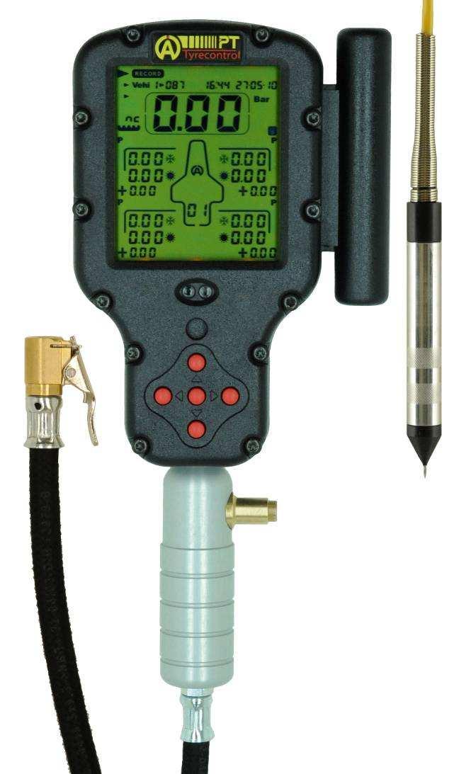
1 TYRECONTROL «PT» A-188 User Manual (EN)
2 2 Introduction The TYRECONTROL «PT» allows you to : - Measure the air pressures - Adjust the air pressures (only to decrease) - Measure the temperatures on the surface of the tyres and the asphalt - Memorize these data until 495 sets for 5 vehicles, either 5x99 sets. 1 set = until 34 captures of data + Hour and Date «before and after race» - With the software "VISUALTYRE" : recover the data recorded for a better analysis and also bring a help to the configuration of your device Replacing the batteries Switch off the device before removing the used batteries to avoid all loss of data recorded. Insert the two new batteries into the device properly and make sure the terminals "+" and "-" are aligned correctly. Battery Type : 2 x AA Important : It is imperative to use quality batteries manufactured by reputed brands in order to prevent battery leakage into the device. A failure caused by the battery acid voids the warranty. Soft number and serial number of the Tyrecontrol When you switch on the Tyrecontrol, the screen displays the soft number below in the middle (2 numbers) and the serial number of the device on top (6 numbers : 3 on the left and 3 on the right) during some seconds. Caution The Tyrecontrol is a device of precision and, of this fact, it is sensitive to the electromagnetic currents coming from the engine ignition. Keep therefore the Tyrecontrol distant (minimum 50cm) of the engine ignition to avoid false readings or a device freezing when the engine is running.
3 3 Switching on the TYRECONTROL - Either normally pressing the central button, the TYRECONTROL starts : WITHOUT the backlight. - Either pressing for 2 seconds the same button, the TYRECONTROL starts : WITH the backlight. Switching off the TYRECONTROL When the Tyrecontrol is not in the menu «OFF», it dies out automatically after 10 minutes of non use. Weak battery detection As soon as the Tyrecontrol detects a weak level of batteries, the word «BAT» appears in most menus while blinking. Working The TYRECONTROL has 8 main options represented by 8 icons :
4 4 This option consists in recording new data. I want to record the pressures and the temperatures for the vehicle 3, with the n 079 assigned. (See menu «SETUP», page 12, «assignment of the numbers of the vehicles» 1) With the help of the buttons, select the icon «RECORD» (figure 1) In the position «RECORD», the Tyrecontrol displays : The hour and the date in real time The pressure in real time (allows a fast measure) The pressures of the last «Set» of the vehicle 1 Figure 1 2) With the button or select the icon «Vehi» (figure 2) 3) With the button or select the vehicle wanted (5 to the total) (figure 2) In the position «VEHI», the Tyrecontrol displays : The hour and the date of the last «Set» of the Vehicle 3 The pressures of this «Set» Figure 2
5 5 4) With the button or, select the «FACE» (figure 3) In the position «FACE», the Tyrecontrol displays : The hour and the date in real time The pressure or the temperature in real time (according to the programmed sequence of capture) Figure 3 On the example (figure 3), the Tyrecontrol is ready to record, for the vehicle 3, a set of captures in the Set «03» before race right rear tyre., («Set» free of the vehicle 3) while starting with a capture of pressure on the Figure 4 Figure 5 Figure 6 5) Apply the mouthpiece of the Tyrecontrol on the valve of the tyre (figure 4) 6) Press the central button to record the measured pressure as well as the hour and the date of the moment, then, the point of capture displayed to the screen moves automatically following the sequence programmed in the menu SETUP. In the example (figure 5), the device positions itself on the measure of the temperature in the center of the left rear tyre.
6 6 7) Apply the sensor of temperature on the tyre as indicated on the screen by the arrow (figure 5). 8) Press the central button to record the measured temperature and prepare the Tyrecontrol on the next point of capture (Figure 6). 9) Operate this way until the end of the programmed sequence. Note : the point of capture asphalts «before and after race». will be chosen automatically at the end of every sequence, 10) Since the hold of the temperature asphalts, the Tyrecontrol returns automatically to the menu «RECORD». Note : it is possible to program a sequence of capture (temperatures and pressures) in the order desired (See Menu «SETUP» page 15, «configuration of the captures sequence». This menu consists in recalling the recorded data. I want to visualize the data of the vehicle 1 with the n 117 assigned. 1) With the help of the buttons, select the icon «RECALL» (figure 8) In the position «RECALL», the Tyrecontrol displays : The hour and the date in real time The pressures of the last «Set» of vehicle 3 2) With the button or, select the icon «Vehi» (figure 9) 3) With the button or, select the vehicle wanted (figure 9) In the position «VEHI», the Tyrecontrol displays : The hour and the date of the last «Set» of the Vehicle 1 The pressures of this «Set»
7 7 4) With the button or, select the «FACE» (figure 10) In the position «CADRAN», the Tyrecontrol displays : Same way as in the position «VEHI» Figure 8 Figure 9 Figure 10 On the example «Figure 10», the Tyrecontrol displays for the vehicle 1, the first phase of data of the last «Set» recorded, that is to say the tires pressures before and after race + the gaps. Figure 11 Figure 12 Figure 13 5) Press the button or : the Tyrecontrol displays the second phase of data, that is to say the outside temperatures of the tires, before and after race + the gaps (figure 11).
8 8 6) Press again the button or : the Tyrecontrol displays the third phase of data, that is to say the temperatures in the center of the tires, before and after race + the gaps (figure 12). 7) Press again the button or : the Tyrecontrol displays the last phase of data, that is to say the inside temperatures of the tires, before and after race + the gaps (figure 13). 8) Press again the button or : the Tyrecontrol displays the first phase of data of first Set. 9) Press systematically the button or to browse all data recorded correspondent in the selected vehicle. 10) Use the button : to browse the data recorded in the inverse sense. - The hour and the date displayed above on the right indicate the moment where the hold of captures of the data has been done, before race (if not yet captures after race) or after race of «Set» displayed. This menu consists in measuring the pressure. 1) With the help of the buttons, select the icon «P». 1) Apply the mouthpiece of the Tyrecontrol on the valve of the tyre. The hour and the date are displayed in real time.
9 9 This menu consists in measuring the temperature. The hour and the date are displayed in real time. 1) With the help of the buttons, select the icon «T». 2) Apply the temperature sensor A481 on the tire. This menu consists in erasing the recorded data. 1) With the help of the buttons, select the icon «RST» (figure 14) 2) With the button or, select the icon «Vehi» (figure 15) 3) With the button or, select the vehicle wanted (figure 15) 4) Press the central button during 1 second, to erase all data of vehicle 1 (figure 16) Figure 14 Figure 15 Figure 16
10 10 This menu consists in transferring the data recorded in the Tyrecontrol toward a computer. 1) With the help of the buttons, select the icon : 2) Apply the interface IR-USB (the A421) on the Tyrecontrol. 3) The command of the function «download» is done from the software VISUALTYRE. This menu consists in switching off the Tyrecontrol. 1) With the help of the buttons, select the icon : 2) Wait for 3 seconds. Note : when the Tyrecontrol is not in the menu «OFF», it dies out automatically after 10 minutes of non use.
11 11 SETUP These menus consist in configuring various parameters of the Tyrecontrol : 01) Assignment of the numbers of the vehicles «menu 01» (page 12) 02) Regulating of the clock and the calendar «menu 02» (page 13) 03) Choice of the unit Bar/PSI «menu 03» (page 14) 04) Choice of the unit C /F «menu 04» (page 14) 05) Choice of the vehicle «menu 05» (page 15) 06) Configuration of the sequence of the captures «menu 06» (page 15) 07) Calibration of the Pressure sensor «menu 07» (page 18) 08) Calibration of the Temperature sensor «menu 08» (page 19) Procedure to reach the SETUP : 1) The Tyrecontrol must be stopped. 2) Press the central button during minimum 5 seconds, the Tyrecontrol starts in the first menu SETUP : «Assignment of the numbers of the vehicles». Procedure to browse the menus SETUP : Press the button or Procedure to leave the mode SETUP : 1) After the menu «Calibration of the Temperature sensor», 2) Press the central button on «EXIT», the Tyrecontrol starts in its normal working on mode «RECORD».
12 01) Assignment of the numbers of the vehicles : 12 1) In this window, press the central button to enter in the menu, «Ent» disappears. 2) With the button or, select the vehicle wanted, choice from 1 to 5, 3) Press the button to modify the number of the vehicle, choice from 0 to 999, 4) With the buttons, modify the number of the vehicle. To activate the fast scrolling of the numbers, maintain the pressed button more than 1 second. To assign a number to another vehicle : 5) Press the button to come back behind, you just need to repeat the operations as explained above from the line 2. 6) Press the central button to leave the menu. Note : After having come out of the menu, only the «Vehi 1» with its assigned number will be visible. Important : - If the number of the vehicle 1 is adjusted on zero, when using the Tyrecontrol, the system won't permit to choose another vehicle.
13 13 02) Regulating of the clock and the calendar : 1) In this window, press the central button to enter in the menu, «Ent» disappears. 2) With the buttons, modify the hour, 3) Press the button to be able to modify the minutes, 4) With the buttons, modify the minutes. To activate the fast scrolling of the numbers, maintain pressed more than 1 second. 5) Press the button to be able to modify the day calendar, 6) With the buttons, modify the day calendar, 7) Press the button to be able to modify the month, 8) With the buttons, modify the month, 9) Press the button, to be able to modify the year, 10) With the buttons, modify the year, 11) Press the button, to come back behind, 12) Press the central button, to come out of the menu.
14 14 03) Choice of the unit Bar/PSI : OR 1) Owing one of these two windows, press the central button to enter in the menu, Ent disappears. 2) With the button or, modify the unit, 3) Press the central button to come out of the menu. 04) Choice of the unit C/ F : OU 1) In one these two windows, press the central button to enter in the menu, «Ent» disappears. 2) With the button or, modify the unit, 3) Press the central button to come out of the menu.
15 15 05) Choice of the vehicle : ou 1) In one of these two windows, press the central button to enter in the menu, «Ent» disappears. 2) With the button or, modify the type of vehicle (Car or Motorbike) 3) Press the central button to come out of the menu. 06) Configuration of the sequence of the captures : ou 1) In one of these two windows (depending on the menu «05»), press the central button to enter in the menu, «Ent» disappears. Note : the explanation below is based on the example of the car.
16 16 2) The first Icon «P» (pressure) on the front left tyre appears by default blinking (figure 17). Figure 17 Figure 18 Figure 19 3) If you want to program the first capture in another place, choose then another icon on the vehicle. For this, you just need to move with the help of the 4 buttons : 4) Press the central button to confirm your choice (figure 18). After confirmation, the icon «P» selected freezes, the number 1 show off in the «CADRAN». Then, another icon appears automatically, blinking, (red arrow, figure 18). If the place of the second capture doesn't suit you, same thing, repeat the operations as explained above (figure 19). In this way, you can create a combination of captures with the priorities between pressures and temperatures as you want them. 5) After having programmed the points of captures as wanted, move on the EXIT icon, with the help of the 4 buttons. 6) Press the central button to leave the menu.
17 17 Figure 20 The «figure 20» shows that 4 captures points of pressures + 4 captures points of temperatures have been programmed with the wanted priorities + the capture point of asphalt temperature. Note : In RECORD mode, the point of capture of the asphalt s temperature automatically at the end of every sequence before and after race. will be chosen The two figures below represent the available capture places On the car (left side) and on the motorbike (right side)
18 18 07) Calibration of the Pressure sensor : 1) In this window, press the central button to enter in the menu, «Ent» disappears. 2) Press the central button to calibrate the sensor of pressure and to leave the menu (figure 23). Figure 21 Figure 22 Note : - It is useful to calibrate the sensor when the FACE indicates a value of pressure whereas no pressure has been entered in the Tyrecontrol (example : figure 21). The mouthpiece of the Tyrecontrol must be free. - IMPORTANT : calibrate the Tyrecontrol with the mouthpiece FREE.
19 19 08) Calibration of the Temperature sensor : 1) In this window, press the central button to enter in the menu, «Ent» disappears. 2) Connect the sensor of temperature (figure 23). 3) With the buttons, adjust the temperature in the «FRAME» so that the displayed temperature corresponds to a temperature of reference (figure 24). Figure 23 Figure 24 Note : - The temperature of reference must come from a precision device giving temperature. - The two sensors of these devices must be placed at the same place. - Wait that the two displayed values stabilize. 4) Press the central button to come out of the menu.
20 20 Warranty conditions All our devices have been subject to in-depth factory tests and are covered by a 24-month warranty against manufacturing defects. The warranty comes into force from the date of purchase. The date of purchase is the date stated on the invoice/till receipt given by the seller at the time of sale. The manufacturer undertakes to repair and replace free of charge any parts which have a manufacturing defect during the warranty period. Any defects which cannot be clearly attributed to the material or the manufacturer will be examined at one of our approved after-sales service centres and invoiced depending on the results. The warranty does not apply in cases of device opening, accidental damage, negligence or misuse, inappropriate or incorrect installation or failure to perform the installation in accordance with the instructions contained in the attention note and in events not associated with the rules of operation and use of the device. The warranty will become null and void in cases of repair or handling carried out by unauthorised third parties. Intervention under warranty does not entitle to the device replacement or warranty extension. Intervention under warranty is carried out at one of our approved after-sales service centres or at our head office. In the latter case, the item must reach our establishment postage paid, that is, transport costs shall be paid by the user. The manufacturer undertakes no responsibility for any damage to persons or goods caused by poor installation or incorrect use of the device. Product modifications Alfano SA applies a method of ongoing development. Consequently, Alfano SA reserves the right to make changes and improvements to any product described in this document without prior notice. Damages and responsibilities The products are used under the customer s sole direction and responsibility and therefore damages suffered or caused by the products shall be borne by the customer. No compensation will be paid for removal of enjoyment, and ALFANO cannot be held responsible for the direct or indirect consequences of their use or rendering useless. ALFANO s obligations are duty of care and not a performance obligation. Disposal The device must be disposed of with respect for environment. The chronometer and its accessories contain many plastic parts. When the chronometer or one of its accessories no longer functions, they must be dealt with according to the laws of the country. Used batteries must be disposed of in accordance with the regulations in force in your country.
21 21 ALFANO S.A. Rue de l Industrie, 3b 1400 NIVELLES (BELGIUM)
AC Irrigation and Propagation Controllers I Four Station, 5006-I and 5006-IP Six Station
 AC Irrigation and Propagation Controllers 5004-I Four Station, 5006-I and 5006-IP Six Station I N S T R U C T I O N M A N U A L Table of contents Introduction 1 1. Specifications 1 2. Controller Mounting
i n s t r u c t i o n m a n u a l
 i n s t r u c t i o n m a n u a l 8006 Six-Station AC Timer Residential/Light Commercial Independent Program Irrigation Controllers Installation, Programming and Operating Instructions Features Operates
SmarTire TPMS Maintenance Hand Tool. Revision User Manual
 SmarTire TPMS Maintenance Hand Tool Revision 1.03 User Manual Page 2 Table of Contents FCC Compliance Label...4 User Interface Illustration...4 Introduction...5 Testing Tire Sensors...5 Main Menu...6 Main
TECHNICAL MANUAL FOR ELECTRONIC SPEEDOMETER STR-RIEJU MATRIX 2
 FOR ELECTRONIC SPEEDOMETER STR-RIEJU MATRIX 2 Rel. 4.0 3.0 2.0 1.0 0.0 Release Disposal Aim Modifications on chapter 8 and 13 Deleted automatic and manual test procedure General modifications Added par.
TWO-WAY LCD AUTOMATIC TRANSMISSION REMOTE STARTER. User Guide
 TWO-WAY LCD AUTOMATIC TRANSMISSION REMOTE STARTER User Guide A note concerning the battery inside the transmitter: Depending on your usage of the transmitter, the battery can last anywhere between 3 to
Andatech SOBERPOINT 3. Wall Mounted Breathalyser USER S MANUAL
 Andatech SOBERPOINT 3 Wall Mounted Breathalyser USER S MANUAL Thank you for purchasing an Andatech Soberpoint 3 breathalyser. The Andatech Soberpoint 3 is a Fuel Sensor type coin- or buttonoperated breathalyser.
Wireless Tire Pressure and Temperature Monitoring System Instruction Manual Model #: TM-507 SCE 507 Commercial Cap Sensors with Monochrome Display
 Wireless Tire Pressure and Temperature Monitoring System Instruction Manual Model #: TM-507 SCE 507 Commercial Cap Sensors with Monochrome Display Thank you for purchasing the TST Tire Pressure Monitoring
PWM Charge Controller with LCD Display 30A. User Manual
 PWM Charge Controller with LCD Display 30A User Manual 1 Product Features 1. 12V/ 24 V system voltages are automatically recognized. 2. Charging program options for sealed, GEL and flooded lead-acid batteries
MDX-300 Series. For 12-volt automotive starting batteries and starting/charging systems INSTRUCTION MANUAL
 For 12-volt automotive starting batteries and starting/charging systems INSTRUCTION MANUAL Blank page Contents Caution... 4 Capabilities... 4 Display and Keypad... 4 Preparations Before the Test... 6 Connecting
USER GUIDE 1 USER GUIDE
 USER GUIDE 1 USER GUIDE 1 TABLE OF CONTENTS IN THE BOX...3 NAVIGATING THE MENUS...3 MENU LAYOUT...3 UPDATE YOUR PROGRAMMER...4 CONNECT WITH THE MOTORCYCLE...5 TUNE YOUR MOTORCYCLE...6 ADDITIONAL FEATURES...8
Fuel Level FL1. FL1 - User s manual. Rev Revision#2.0, 28/11/2014 For firmware version 1.2
 Fuel Level FL1 Revision#2.0, 28/11/2014 For firmware version 1.2 FL1 - User s manual Page intentionally left blank SECTIONS MECHANICAL INSTALLATION ELECTRICAL INSTALLATION OPERATING INSTRUCTIONS INSTRUMENT
HP Series Smart Solar Charge Controller HP2430/2440/2450/2460 HP4830/4840 UserManual
 HP Series Smart Solar Charge Controller HP2430/2440/2450/2460 HP4830/4840 UserManual Dear users Thank you for choosing our product. Before using the product, please read this manual carefully.productfeatur
MDX-645 INSTRUCTION MANUAL. Battery Conductance Analyzer. For 6 & 12-volt automotive starting batteries
 MDX-645 Battery Conductance Analyzer For 6 & 12-volt automotive starting batteries INSTRUCTION MANUAL Blank page Contents Safety Guidelines 5 Capabilities 5 Registering Your MDX-Series Tester 7 Display
DT304. Digital Temperature Logger INSTRUCTION MANUAL
 Test Equipment Depot - 800.517.8431-99 Washington Street Melrose, MA 02176 - TestEquipmentDepot.com DT304 INSTRUCTION MANUAL Digital Temperature Logger TABLE OF CONTENTS Introduction..........................................1
TABLE OF CONTENTS. Page 1
 TABLE OF CONTENTS Safety Precautions and Warnings... 2 Introduction... 3 EZ-CHARGE Battery Conductance Testers... 3 EZ-CHARGE 100 Features... 3 EZ-CHARGE 200 Features... 4 Text Styles Used in this Manual...
SI AT A22. English. Printed: Doc-Nr: PUB / / 000 / 01
 SI AT A22 English 1 Information about the documentation 1.1 About this documentation Read this documentation before initial operation or use. This is a prerequisite for safe, trouble-free handling and
Grain Moisture Meter. Operators manual
 Grain Moisture Meter Operators manual Operation EN COMPONENTS 1 TESTER 2 BATTERY DOOR 3 USB DOOR 4 USB CABLE 5 CARRYING CASE 1 4 2 5 3 A A - Test Cell B - Display C - Keyboard D - Cap E - Pressure-indicator
Bante220 Portable ph Meter Instruction Manual
 Bante220 Portable ph Meter Instruction Manual BANTE INSTRUMENTS CO., LTD Bante220 Portable ph Meter 1 Introduction Thank you for selecting the Bante220 portable ph meter. This manual provides a step-by-step
SI AT A22. English. Printed: Doc-Nr: PUB / / 000 / 03
 SI AT A22 English 1 Information about the documentation 1.1 About this documentation Read this documentation before initial operation or use. This is a prerequisite for safe, trouble-free handling and
SmarTire TPMS Maintenance Hand Tool. Revision User Manual
 SmarTire TPMS Maintenance Hand Tool Revision 1.04 User Manual Page 2 Table of Contents FCC Compliance Label... 4 User Interface Illustration... 4 Introduction... 5 Testing Tire Sensors... 5 Main Menu...
6. Pre-print checks. 3D Touch
 Page 1 1. 6. Pre-print checks........................................................................................... 1.1 a. Clearing the print bed..................................................................................
CAM-PTZ-AUT Tracking Module for PTZ Camera Installation & User Manual
 CAM-PTZ-AUT Tracking Module for PTZ Camera Installation & User Manual i / iii Thank You for Choosing Aventura's CAM-PTZ-AUT Tracking Module for PTZ Cameras! When you open the box: Check that the packing
The RCS-6V kit. Page of Contents. 1. This Book 1.1. Warning & safety What can I do with the RCS-kit? Tips 3
 The RCS-6V kit Page of Contents Page 1. This Book 1.1. Warning & safety 3 1.2. What can I do with the RCS-kit? 3 1.3. Tips 3 2. The principle of the system 2.1. How the load measurement system works 5
Instruction of connection and programming of the VECTOR controller
 Instruction of connection and programming of the VECTOR controller 1. Connection of wiring 1.1.VECTOR Connection diagram Fig. 1 VECTOR Diagram of connection to the vehicle wiring. 1.2.Connection of wiring
For questions or technical support, 1. Wiring Reference:
 Warning: Before proceeding you are obligated to read and agree to the terms and conditions attached to this manual. Misuse of this product may cause injury or death. Incorrect installation may cause damage
Volkswagen Information System. Introduction
 Volkswagen Information System Introduction In this section you ll find information about: Using the instrument cluster menus: Basic version Using the instrument cluster menus: Premium version with multi-function
Breath Alcohol Tester
 Breath Alcohol Tester Professional Fuel cell sensor Personal & professional use alcohol tester AF-50 Instruction Manual 50 sets of data memory Professional Fuel Cell Sensor Law enforcement grade accuracy
Wireless Tire Pressure and Temperature Monitoring System Instruction Manual Model #: TM Cap Sensors
 Wireless Tire Pressure and Temperature Monitoring System Instruction Manual Model #: TM-510 510 Cap Sensors Thank you for purchasing the TST Tire Pressure Monitoring System. With minimal care, your new
Service menu - Individual Filament Calibration
 Service menu - Individual Filament Calibration Written By: Jakub Dolezal 2018 manual.prusa3d.com/ Page 1 of 8 Step 1 Introduction This guide will take you through the calibration of the Bowden length on
Setup and Configuration Guide Universal Switch Interface
 Table of Contents J1939 inmotion Cell Setup and Configuration Guide Universal Switch Interface Overview... 2 Warnings... 3 J1939 inmotion Cell Technical Details... 4 inmotion Cell Installation Steps...
MICROCARE 3 PHASE INVERTER MANUAL
 3 PHASE INVERTER MANUAL 1 Contents 1. INTRODUCTI... 3 2. SAFETY INSTRUCTI... 4 3. SYSTEM DESCRIPTI... 6 4. WIRING DIAGRAM... 9 5. INVERTER OPERATI... 10 6. INVERTER CLUSTER PROGRAMMING... 13 7. CLUSTER
ECONOMISER SERIES E2T USER MANUAL
 TURBO S.R.L. Electronic Control Systems for Dust Collectors e-mail: info@turbocontrols.it web: www.turbocontrols.it TEL. ++39 (0)362 574024 FAX ++39 (0)362 574092 ECONOMISER SERIES E2T USER MANUAL 24/06/2014
Solar TPMS. Operating Manual
 The sales package may offer products with color on color or packaging shown in this manual are different. Picture only for reference, technical specifications subject to change without notice. Parts supply
Solar TPMS. Operating Manual
 The sales package may offer products with color on color or packaging shown in this manual are different. Picture only for reference, technical specifications subject to change without notice. Parts supply
BBT-205. For 12-volt automotive starting batteries and starting/charging systems INSTRUCTION MANUAL
 For 12-volt automotive starting batteries and starting/charging systems INSTRUCTION MANUAL Blank page Contents Registering Your tester... 5 Caution... 6 Capabilities... 6 Display and Keypad... 6 Preparations
POLE STAR PRO. Installation and instruction manual.
 POLE STAR PRO Installation and instruction manual. POLE STAR PRO is an automatic chrono and rev counter with a LED bar and Shift light which can be set, an indispensable instrument for drivers of: Go Karts
(If this step is missed, then OBD software is not going to work. So it's CRUCIAL that you follow below steps).
.") How to Install ELM327 USB/Bluetooth on Mac and OBD Software Posted by Alex (Im) E. on 28 January 2013 02:53 AM This article will guide you on how to install ELM327 USB Cable / Bluetooth scanner on your
How to Install ELM327 USB/Bluetooth on Mac and OBD Software Posted by Alex (Im) E. on 28 January 2013 02:53 AM This article will guide you on how to install ELM327 USB Cable / Bluetooth scanner on your
PowerView PV380-R2 Mechanical Configuration
 PowerView PV380-R2 Mechanical Configuration Operations Manual *Products covered in this document comply with European Council electromagnetic compatibility directive 2004/108/EC and electrical safety directive
ECLIPSE Laundry Dispenser Controller
 ECLIPSE Laundry Dispenser Controller Reference Manual Programming and Operation Online and downloadable Product Manuals and Quick Start Guides are available at www.hydrosystemsco.com Please check online
Battery Management Innovation. For 12-volt automotive starting batteries and starting/charging systems INSTRUCTION MANUAL
 Battery Management Innovation For 12-volt automotive starting batteries and starting/charging systems INSTRUCTION MANUAL ! CAUTION Because of the possibility of personal injury, always use extreme caution
Quick Guide. Unipro Laptimer Version Go faster faster. UNIPRO ApS
 Quick Guide Unipro Laptimer 5004 Version 1.32 Go faster faster UNIPRO ApS VIBORG HOVEDVEJ 24 DK-7100 VEJLE DENMARK Tel.: +45 75 85 11 82 Fax: +45 75 85 17 82 www.uniprolaptimer.com mail@uniprolaptimer.com
USER MANUAL LEVER LOCK DIGITAL TOUCHPAD TEMPLATE. 120x165(mm)
") 120x165(mm) Mark Ø1" (25.4mm) hole at center of door edge. 2" 1-3/4" 1-9/16" 1-3/8" 51 45 40 35 FOR ( ) 2-3/8 60mm BACKSET Fit here on door edge FOR ( ) 2-3/4 70mm BACKSET TEMPLATE Limited Warranty Statements
120x165(mm) Mark Ø1" (25.4mm) hole at center of door edge. 2" 1-3/4" 1-9/16" 1-3/8" 51 45 40 35 FOR ( ) 2-3/8 60mm BACKSET Fit here on door edge FOR ( ) 2-3/4 70mm BACKSET TEMPLATE Limited Warranty Statements
TABLE OF CONTENTS. Introduction
 TABLE OF CONTENTS Introduction---------------------------------------------------------------------------------------- 1 Correct Measurement---------------------------------------------------------------------------
Model DS7060 Handrail Scale. User Manual
 Model DS7060 Handrail Scale User Manual Doran Scales, Inc. 1315 Paramount Pkwy Batavia, IL 60510 USA 1-800-264-4107 www.doranmedical.com MAN0302 Revision 0.0 TNW 2/20/2013 Section 1. Unpacking and Installation...
Owners Manual for TPMS plus GPS
 To ensure correct operation and service please read these instructions before installing and operating the TPMS feature of the TPMS/GPS unit. Owners Manual for TPMS plus GPS TABLE OF CONTENTS TIRE PRESSURE
USING SCAN TOOL MEMORY
 Table of Contents SAFETY PRECAUTIONS SAFETY FIRST!... 1 BATTERY REPLACEMENT... 6 SCAN TOOL CONTROLS CONTROLS AND INDICATORS... 3 DISPLAY FUNCTIONS... 4 USING THE SCAN TOOL CODE RETRIEVAL PROCEDURE... 7
Wireless Tire Pressure and Temperature Monitoring System Color Display Manual. Wide Screen Color Display Model #: TST-507-D-C
 Wireless Tire Pressure and Temperature Monitoring System Color Display Manual Wide Screen Color Display Model #: TST-507-D-C Thank you for purchasing the TST Tire Pressure Monitoring System. With minimal
BRAKE TESTER DECELEROMETER
 OC3010_GBM_21009 BRAKE TESTER DECELEROMETER OWNER S MANUAL Version 8.++ ORBIT CONTROLS AG Zürcherstrasse 137 CH-8952 Schlieren/ZH Tel: + 41 44 730 2753 Fax: + 41 44 730 2783 info@orbitcontrols.ch www.orbitcontrols.ch
Features: Enhanced throttle response, excellent acceleration, linearity and driveability
 120A/150A ESC X-Car 120A/150A Series Sensored/Sensorless Brushless ESC for 1:8 scale Car or Truck Thank you for purchasing the X-Car Brushless Electronic Speed Controller (ESC). The X-Car 1:8 Scale 120A/150A
MPPT SOLAR CONTROLLER FOR MODELS: 20A baterai 12V 24V
 Main Features MPPT SOLAR CONTROLLER FOR MODELS: 20A baterai 12V 24V 20A MPPT solar charge controller MPPT technology Built-in DSP controller with high performance Automatic battery voltage detection for
Kit User Guide. Wireless Digital Controller User Guide
 Kit 72000 Wireless Digital Controller User Guide UG-681 (03902) ECR 6629 User Guide For maximum effectiveness and safety, please read these instructions completely before proceeding with installation.
CONTENTS. Introduction. Thank you for purchasing the AlcoSense Precision+ breathalyser.
 User Manual Introduction CONTENTS Thank you for purchasing the AlcoSense Precision+ breathalyser. The AlcoSense Precision+ is certified to Australian Standard AS3547 Type 2 Quantitative Device and is one
Table of Contents 1. INTRODUCTION GENERAL INFORMATION-ABOUT OBDII/EOBD PRODUCT DESCRIPTIONS OPERATIONS...11
 Table of Contents 1. INTRODUCTION...1 2. GENERAL INFORMATION-ABOUT OBDII/EOBD...1 2.1 ON-BOARD DIAGNOSTICS (OBD) II...1 2.2 DIAGNOSTIC TROUBLE CODES (DTCS)...2 2.3 LOCATION OF THE DATA LINK CONNECTOR (DLC)...3
Andatech PRODIGY USER MANUAL
 Andatech PRODIGY USER MANUAL INTRODUCTION CONTENTS Thank you for purchasing an Andatech Prodigy S. The Andatech Prodigy S is a state-of-the-art instrument used to detect ethyl alcohol from a valid breath
Important instructions
 Operation manual Please read this manual, before starting the unit. It contains important notes on commissioning and handling. Keep these instructions for future reference. Be careful even if you pass
IMEON 9.12 USER MANUAL
 IMEON 9.12 USER MANUAL USER MANUAL IMEON Modifications Index Indiex Date Modified pages Modification description Author A 30/09/2015 - Initial drafting F.M. Reference IMEON 9.12 Indiex A IMEON 9.12 Smart
MODEL MVX-2011 TANK MOUNT SPEEDOMETER/TACHOMETER
 MODEL MVX-2011 TANK MOUNT SPEEDOMETER/TACHOMETER Wiring Diagram The MVX-2011 gauges will work on 2011-up Softail models with 5 gauges or 2012-up Dyna models with 5 gauges. It is a direct plug in on these
(The following instructions are an excerpt from the Record CG3 User Guide) 4.5 Setting up the CG3 OBDII Interface
 4.5 Setting up the CG3 OBDII Interface") (The following instructions are an excerpt from the Record CG3 User Guide) 4.5 Setting up the CG3 OBDII Interface As of Software Version 1.18, the CG3 provides a superior alternative to measuring distance
(The following instructions are an excerpt from the Record CG3 User Guide) 4.5 Setting up the CG3 OBDII Interface As of Software Version 1.18, the CG3 provides a superior alternative to measuring distance
Section 55 Chapter 6
 Section 55 Chapter 6 REMOTE HYDRAULICS CONTROLLER Calibration and Fault Codes 6-12880NH TABLE OF CONTENTS REMOTE HYDRAULICS CONTROLLER CALIBRATION... 55-5 Requirements For Calibration... 55-5 Aux Set Main
Models CB6 Series (CB66-VE)
") Models CB6 Series (CB66-VE) 1. CONTROL PANEL The machine control panel is shown in Figure F1. The control panel allows the operator to give commands and enter or modify data. The same control panel displays
Models CB6 Series (CB66-VE) 1. CONTROL PANEL The machine control panel is shown in Figure F1. The control panel allows the operator to give commands and enter or modify data. The same control panel displays
Operators Guide: RoboSign Stop/Go Traffic Control System
 Operators Guide: RoboSign Stop/Go Traffic Control System RoboSign Remote controlled Stop/Go temporary traffic control system Operators Guide NZTA Conditions - Automated Stop/Go Traffic Control System NZTA
User manual Temperature Calibrator JOFRA CTC-140/320/650 A/B JOFRA CTC-1200 A Copyright 2005 AMETEK DENMARK A/S ( UK)
") User manual Temperature Calibrator JOFRA CTC-140/320/650 A/B JOFRA CTC-1200 A Copyright 2005 AMETEK DENMARK A/S (123199-UK) FIG. 1 1 2 3 4 5 CALI BRAT ION I NSTRUM ENTS 6 + - Switch Test RS232 7 8 11
User manual Temperature Calibrator JOFRA CTC-140/320/650 A/B JOFRA CTC-1200 A Copyright 2005 AMETEK DENMARK A/S (123199-UK) FIG. 1 1 2 3 4 5 CALI BRAT ION I NSTRUM ENTS 6 + - Switch Test RS232 7 8 11
Lumitester PD-30. Instruction Manual. Table of Contents
 Table of Contents Lumitester PD-30 Instruction Manual Thank you very much for purchasing the Lumitester PD-30. All of this Instruction Manual must be read before operation of this product for safe and
TWO-WAY LED AUTOMATIC TRANSMISSION REMOTE STARTER. User Guide WARNING
 TWO-WAY LED AUTOMATIC TRANSMISSION REMOTE STARTER User Guide WARNING It is the responsibility of the vehicle operator to ensure their vehicle is parked in a safe and responsible manner. 1. When leaving
i n s t r u c t i o n m a n u a l
 Model 510.xxxP Battery Operated Propagation and Irrigation Controller i n s t r u c t i o n m a n u a l Installation, Programming and Operating Instructions Features Weekly or cyclical program Four start
MDX-653P INSTRUCTION MANUAL. Battery Conductance and Electrical System Analyzer
 Battery Conductance and Electrical System Analyzer For 6 & 12-volt automotive starting batteries and 12 & 24-volt starting/charging systems INSTRUCTION MANUAL Blank page Contents Introduction & Overview
WARNING! DO NOT WELD TO THE WEIGH BARS OR ANY STRUCTURE THAT THEY ARE ATTACHED TO
 WEIGHING SYSTEMS T30 Instruction Manual Installation Locate a weighing site that is well drained. For best weighing results, ensure the weigh bars and weighing platform are on a level hard surface (i.e.
Components. Options Accessory Harness USB Charger. Quick Connector. Hook & Loop / Cable-ties. RFID Antenna. Module. Main Harness.
 SRX SERIES Table of Contents - Components - Planning The Install - Mounting - Switched Power - Attach Accessory Harness - Plug In Module - Back-Up Battery - Remote Encoding - 2-Way RFID Remote User Instructions
CO95. Carbon Monoxide Detector INSTRUCTION MANUAL ENGLISH Fax: (503)
") CO95 Carbon Monoxide Detector INSTRUCTION MANUAL ENGLISH CO95 C ARBON MONOXIDE DETECTOR 1-800-547-5740 Fax: (503) 643-6322 www.ueitest.com Email: info@ueitest.com TABLE OF CONTENTS Introduction... 3 Safety...
CO95 Carbon Monoxide Detector INSTRUCTION MANUAL ENGLISH CO95 C ARBON MONOXIDE DETECTOR 1-800-547-5740 Fax: (503) 643-6322 www.ueitest.com Email: info@ueitest.com TABLE OF CONTENTS Introduction... 3 Safety...
Instruction Manual. Duo-battery Solar Panel Controller EPIP20-DB series For Both 10 and 20 amp. Controllers (for use with solar panels only) + -
 + -") Instruction Manual Duo-battery Solar Panel Controller EPIP20-DB series For Both 10 and 20 amp. Controllers (for use with solar panels only) + - Optional - Switch to disconnect solar panel when engine alternator
Instruction Manual Duo-battery Solar Panel Controller EPIP20-DB series For Both 10 and 20 amp. Controllers (for use with solar panels only) + - Optional - Switch to disconnect solar panel when engine alternator
CA611 Owners Manual CAUTION!
 CA611 Owners Manual CAUTION! Be certain that the vehicle is outdoors before using this or any remote vehicle starting device. A running engine produces dangerous carbon monoxide fumes which can be harmful
Installation Guide Smart-UPS On-Line External Battery Pack XBP48RM1U-LI
 Installation Guide Smart-UPS On-Line External Battery Pack XBP48RM1U-LI Important Safety Messages Read the instructions carefully to become familiar with the equipment before trying to install, operate,
Installation and User Manual. with RAIN SENSOR.
 with RAIN SENSOR www.solarsmartopener.com Revision..0 TABLE OF CONTENTS Features In The Box Further Items Required Basic Operation Solar Panel and Operator Installation Operator Installation Solar Panel
MoistureMatch A next generation grain tester
 MoistureMatch A next generation grain tester A next generation moisture tester incorporating new and unique technology. Finally, a portable tester that will more accurately match and track with the commercial
Where There is Miboxer There is Power. User Manual. Model No.: C2-6000
 Where There is Miboxer There is Power User Manual Model No.: C2-6000 Introduction C2-6000 is a highly advanced battery charger, that includes a power bank function. The charger automatically adapts the
Hickok assumes no responsibility for use of this equipment by untrained or unauthorized persons.
 user Guide 2013 Hickok Inc. All rights reserved. All rights reserved. No part of this manual may be reproduced or transmitted in any form or by any means, electronic or mechanical, without written permission
CATEYE URBAN WIRELESS+
 CATEYE URBAN WIRELESS+ CYCLOCOMPUTER CC-VT5W Mounting the computer Setting up the computer Starting measurement This instruction manual is subject to change without notice. See our website for the latest
Installation Power Management Unit Battery Cables and Battery Harness
 Installation Power Management Unit Battery Cables and Battery Harness Important Safety Messages SAVE THESE INSTRUCTIONS - This manual contains important instructions that should be followed during installation
Instruction Manual. Model 307A Analog Insulation & Continuity Meter
 Instruction Manual Model 307A Analog Insulation & Continuity Meter Index Page Safety Precautions... 1 Safety Notes... 2 Features... 2-3 Connections... 3 Specifications...... 4 Why Test is necessary...
Operators Guide: RoboSign Stop/Go Traffic Control System
 Operators Guide: RoboSign Stop/Go Traffic Control System RoboSign Remote controlled Stop/Go temporary traffic control system Operators Guide Table of Contents Operators Guide: RoboSign Stop/Go Traffic
700G Series. Users Manual. Pressure Gauge
 700G Series Pressure Gauge Users Manual November 2011 Rev. 1, 10/13 2011-2013 Fluke Corporation. All rights reserved. Specifications are subject to change without notice. All product names are trademarks
RF-51-eDp. Operation guide. Deluxe 2-way Oem Upgrade & Range extender. July 22, 2014
 RF-51-eDp Deluxe 2-way Oem Upgrade & Range extender July 22, 2014 Operation guide Man nuales En Español Table Of Contents Controller & Transmitter Overview... 3 The 2-Way Controller... 3 The 1-Way Transmitter...
Owner s Manual Ford Powerstroke 7.3 liter CAUTION: THIS IS A HIGH PERFORMANCE PRODUCT. USE AT YOUR OWN RISK.
 Owner s Manual 1994 2003 Ford Powerstroke 7.3 liter CAUTION: THIS IS A HIGH PERFORMANCE PRODUCT. USE AT YOUR OWN RISK. Edge Products Inc distributed by BD Power Evolution FORD Powerstroke 7.3 liter - 1
Breath Alcohol Tester
 Breath Alcohol Tester Advanced fuel cell sensor Personal & professional use alcohol tester DA-8000 Instruction Manual DA-8000 Fuel cell ( Electrochemical) accuracy 4-digit LCD display with a backlit User
A U T O M A T I C T R A N S M I S S I O N M U L T I - C H A N N E L T W O - W A Y L C D R E M O T E S T A R T E R AS-2510 TW.
 A U T O M A T I C T R A N S M I S S I O N M U L T I - C H A N N E L T W O - W A Y L C D R E M O T E S T A R T E R S Y S T E M AS-2510 TW User Guide Transmitter Part Number and Module Serial Number...2
INTRODUCTION. Specifications. Operating voltage range:
 INTRODUCTION INTRODUCTION Thank you for purchasing the EcoPower Electron 65 AC Charger. This product is a fast charger with a high performance microprocessor and specialized operating software. Please
Thermometer models 02023/02028/02053/02054
 Instruction Manual Thermometer models 02023/02028/02053/02054 CONTENTS Unpacking Instructions... 2 Package Contents... 2 Product Registration... 2 Features & Benefits... 3 Setup... 4 Set the Time & Units...
3 40W. Product Introduction. 1440mm(56.7in) 560mm (22in) 440mm (17.3in
 560mm (22in) 440mm (17.3in") Product Introduction 1440mm(56.7in) 560mm(22in) 1 3 9 7 2 6 8 560mm (22in) 4 440mm (17.3in 5 Items 1 3x40 Watts Solar Panel 2 10A Charge Controller 3 Alligator clips 4 Suitcase with handle and pocket 5
Product Introduction 1440mm(56.7in) 560mm(22in) 1 3 9 7 2 6 8 560mm (22in) 4 440mm (17.3in 5 Items 1 3x40 Watts Solar Panel 2 10A Charge Controller 3 Alligator clips 4 Suitcase with handle and pocket 5
Harness the Power of the Sun
 Harness the Power of the Sun Solar Controller / Battery Charger User s Manual Nominal Voltage: 12Volts Rated Solar Current: 30Amps / 40Amps Nominal Voltage: 12Volts / 24Volts Auto Rated Solar Current:
Rutland Remote Display -Model Installation and Operation
 Rutland Remote Display -Model 1200 Installation and Operation Introduction The Rutland Remote 1200 Model is designed for use with the Rutland 1200 Wind Turbine. It enables convenient viewing of the wind
 WWW.MORETRACTION.COM TMS-5500-SL ELECTRONIC TRACTION CONTROL US PATENT 6,577,944 Other Patents Pending COPYRIGHT NOTICE Copyright 1999-2013 Davis Technologies, LLC. All rights reserved. Information in
SAC SERIES CONTENTS TRIPLE-INTERVAL HIGH PRECISION COUNTING SCALE OPERATION MANUAL 1. INSTALLATION 2. SPECIFICATIONS
 CONTENTS SAC SERIES TRIPLE-INTERVAL HIGH PRECISION COUNTING SCALE 1. INSTALLATION 2. SPECIFICATIONS 2.1 GENERAL SPECIFICATIONS 2.2 MINIMUM PIECES, WEIGHT APPLIED & SAMPLE SIZE WEIGHT SPECIFICATIONS OPERATION
Thermometer models 02023, 02028, 02029
 Instruction Manual Thermometer models 02023, 02028, 02029 CONTENTS Unpacking Instructions... 2 Package Contents... 2 Product Registration... 2 Features & Benefits... 3 Setup... 4 Set the Time, Date & Units...
SAFETY PRECAUTIONS SAFETY FIRST!... 1 ABOUT THE CODE READER CONTROLS AND INDICATORS... 3 DISPLAY FUNCTIONS... 4
 Table of Contents SAFETY PRECAUTIONS SAFETY FIRST!... 1 ABOUT THE CODE READER CONTROLS AND INDICATORS... 3 DISPLAY FUNCTIONS... 4 USING THE CODE READER CODE RETRIEVAL PROCEDURE... 7 VIEWING ABS DTCs...
OBDII/EOBD Heavy truck Diagnostic tool. User manual. 2.8 Color display
 OBDII/EOBD Heavy truck Diagnostic tool User manual 2.8 Color display Table of Contents 1. Safety Precautions and Warnings... 3 2. General Information... 4 2.1 About DTC... 4 2.2 J1708/J1587/J1939... 4
FOR SERVICE SEND TO: AUTO METER PRODUCTS, INC. 413 W. Elm St., Sycamore, IL USA (815) us at
 us at") 2650-887F INSTALLATION INSTRUCTIONS 5 single channel ultimate tach COPYRIGHT PATENT 5 4 6 3 PENDING 7 8 PLAYBACK 9 2 0 1 AUTO METER PRODUCTS, INC. SYCAMORE, IL USA MADE R P M X1000 IN USA ENTER START PAUSE
2650-887F INSTALLATION INSTRUCTIONS 5 single channel ultimate tach COPYRIGHT PATENT 5 4 6 3 PENDING 7 8 PLAYBACK 9 2 0 1 AUTO METER PRODUCTS, INC. SYCAMORE, IL USA MADE R P M X1000 IN USA ENTER START PAUSE
THIS MANUAL DESCRIBES THE SMARTCRAFT GAUGE SYSTEMS AVAILABLE FOR YOUR BOAT
 Systems Monitor Operation Manual THIS MANUAL DESCRIBES THE SMARTCRAFT GAUGE SYSTEMS AVAILABLE FOR YOUR BOAT 2004, Mercury Marine 90-895202 204 0 TABLE OF CONTENTS Legend..............................................
Advanced Hybrid Wind / Solar Charge Controller. User Manual
 Advanced Hybrid Wind / Solar Charge Controller User Manual Safety 1. Please read the instructions carefully prior to product use or installation and refer back to them throughout the installation. 2. This
Begin to Use The New ESC: Before use the new ESC please carefully check every connections are correct or not. Yellow motor wire B Blue motor wire A
 HIMOTO ZTW Brushless Electronic Speed Control for car or truck Thank you for purchasing ZTW Brushless Electronic Speed Controller(ESC). The ZTW electronic speed control (ESC) is specifically designed for
SERVICE MANUAL. STARTER Portable Meter ST300 ST300C ST300D ST400D. Ohaus Corporation, 7 Campus Drive, Suite 310, Parsippany, NJ (973)
") SERVICE MANUAL STARTER Portable Meter ST300 ST300C ST300D ST400D Ohaus Corporation, 7 Campus Drive, Suite 310, Parsippany, NJ 07054 (973) 377-9000 SERVICE MANUAL STARTER Portable Meter ST300 ST300C ST300D
SERVICE MANUAL STARTER Portable Meter ST300 ST300C ST300D ST400D Ohaus Corporation, 7 Campus Drive, Suite 310, Parsippany, NJ 07054 (973) 377-9000 SERVICE MANUAL STARTER Portable Meter ST300 ST300C ST300D