Atlas ESR and ESR + Equivalent Series Resistance and Capacitance Meter. Model ESR60/ESR70. Designed and manufactured with pride in the UK.
|
|
|
- Duane Grant
- 6 years ago
- Views:
Transcription


1 GB60/70-9 Atlas ESR and ESR + Equivalent Series Resistance and Capacitance Meter Model ESR60/ESR70 Designed and manufactured with pride in the UK User Guide Peak Electronic Design Limited 2004/2016 In the interests of development, information in this guide is subject to change without notice - E&OE
2 Want to use it now? We understand that you want to use your Atlas ESR right now. The unit is ready to go and you should have little need to refer to this user guide, but please make sure that you do at least take a look at the notices on page 4! Contents Page Introduction...3 Important Considerations...4 Notes on ESR...5 Analysing capacitors Typical values of ESR Audible Alerts...11 Probe Compensation...12 Care of your Atlas ESR...13 Appendix A Troubleshooting...14 Appendix B Technical Specifications...15 Appendix C Statutory Information...16 Page 2
3 Introduction The Atlas ESR is an advanced instrument designed specifically for the analysis of capacitor equivalent series resistance (in or out of circuit). In addition it will, where possible, display the capacitance of the device under test. Summary Features: ESR measurement range 0 to 20Ω (40Ω for ESR70). ESR resolution as low as 0.01Ω. Capacitance range 1µF to 22000µF. Can be used for low-ohms resistance checking too. Integrated controlled discharge circuitry reduces the need for the user to manually discharge capacitors before test.* Use in or out of circuit for ESR and low-ohms resistance measurement. The ESR70 features audible alerts for quick user-feedback of ESR test status. Automatic analysis start when component is detected. Automatic and manual power-off. * Note: The discharge circuitry exists to ensure that a charged capacitor is less likely to damage the unit. For example, if the capacitor under test has a potential of a few tens of volts across it, the charge is removed automatically. It is the user s responsibility to ensure that any dangerously charged capacitors are safely discharged before connection to the unit. Page 3
4 Important Considerations Please observe the following guidelines: This instrument must NEVER be connected to powered equipment/components. It is the user s responsibility to ensure that any dangerously charged capacitors are safely discharged before connection to the unit. To allow the self-protection mechanism to function, always ensure that the Atlas ESR has completed any analysis before connecting the test probes to a component. Failure to comply with these warnings may result in personal injury, damage to the equipment under test, damage to the Atlas ESR and invalidation of the manufacturer's warranty. Avoid rough treatment, hard knocks and extreme temperatures. This unit is not waterproof. Page 4
5 Notes on ESR ESR (Equivalent Series Resistance), as its acronym implies, is the value of resistance that is effectively in series with an ideal capacitor. ESR C No capacitor is ideal of course, the detailed equivalent circuit of a typical capacitor is very complex. For many electrolytic capacitors however, the most important parameters regarding the capacitor s performance is the capacitance and the ESR. An increase in ESR (due to age, abuse or temperature cycling) can result in poor capacitor performance. The capacitor becomes less ideal and starts to dissipate more power, an ideal capacitor of course dissipates zero power. Capacitor manufacturers typically quote the ESR of their products at 100kHz, which is the same test frequency used by the Atlas ESR. Sometimes, manufacturers quote ESR at 100Hz or 120Hz as the capacitors may be aimed at rectified mains power applications. ESR is generally not frequency dependent however, so it can be reasonably considered equivalent to readings taken at 100kHz. Page 5
6 Analysing Capacitors The Peak Atlas ESR is designed to analyse capacitor ESR in or out of circuit. The two test probes can be connected to the component any way around. Remember though that in-circuit testing can result in less accurate readings. Important: To minimise risk of damage to the unit, make sure that the Atlas ESR has completed any previous analysis before attaching the test probes to the capacitor. This ensures that the built-in protection circuit is ready for any charge that may be present on the capacitor. The Atlas ESR must first be switched on by briefly pressing the on-test button. The unit will start a component analysis when it detects that the open circuit probes have been applied to a component or when on-test button is re-pressed. If the capacitor is charged (<50V), the Atlas ESR will attempt to discharge the capacitor while showing the progress of the procedure: If the Atlas ESR cannot recognise the component connected to the test probes, or the capacitance is out of range, the following message may be displayed: Monitoring for component... Analysing... Discharging... Capacitor V= 23V Open circuit or low capacitance. Page 6
7 Analysing Capacitors continued The ESR analysis typically takes under 2 seconds to complete, followed by up to around 10 seconds for the capacitance measurement (depending on the characteristics of the capacitor). As soon as a valid ESR reading has been obtained, the ESR value is displayed while the instrument proceeds to measure the capacitance. If the presence of external circuitry did not adversely affect the capacitance measurement, the capacitor value will be displayed. If the capacitance could not be determined (perhaps it is in-circuit or a leaky capacitor), the display will only show the value of ESR measured. Measuring C... ESR = 0.21 Cap = 476.6µF ESR = 0.21 In-Circuit/Leaky ESR = 0.21 It is not necessary to wait for the capacitance measurement to complete if you re not interested in the capacitance value. If the probes are removed from the component under test before the capacitance measurement has (C not measured) completed, the display will confirm that ESR = 0.21 the capacitance has not be measured: It can be useful to disconnect the probes before the capacitance measurement has completed if you re wanting to simply check the ESR of multiple components in succession. Page 7
8 Analysing Capacitors continued In the event that ESR exceeds the maximum that can be measured, the display may show: Cap = 476.6µF ESR = >20.0 or In-Circuit/Leaky ESR = >20.0 The ESR measurement range is automatically determined during the analysis. Typically, the resolution for ESR measurement is as shown in the table below: Automatically Nominal measured ESR Value selected test current resolution 0.00 Ω 2.00 Ω 20mA 0.01 Ω 2.0 Ω 20.0 Ω* 2mA 0.1 Ω 20.0 Ω 40.0 Ω* 1mA 0.2 Ω Although the measurement resolution is generally determined by the absolute value of the ESR (as shown in the above table), low capacitance values can result in a poorer ESR measurement resolution. * The maximum ESR measurement is limited to 20Ω for the model ESR60 and 40Ω for the model ESR70. If measuring capacitors connected in parallel, the ESR reading will effectively be the value of all the ESRs in parallel, not just the ESR of the capacitor in contact with the probes. Page 8
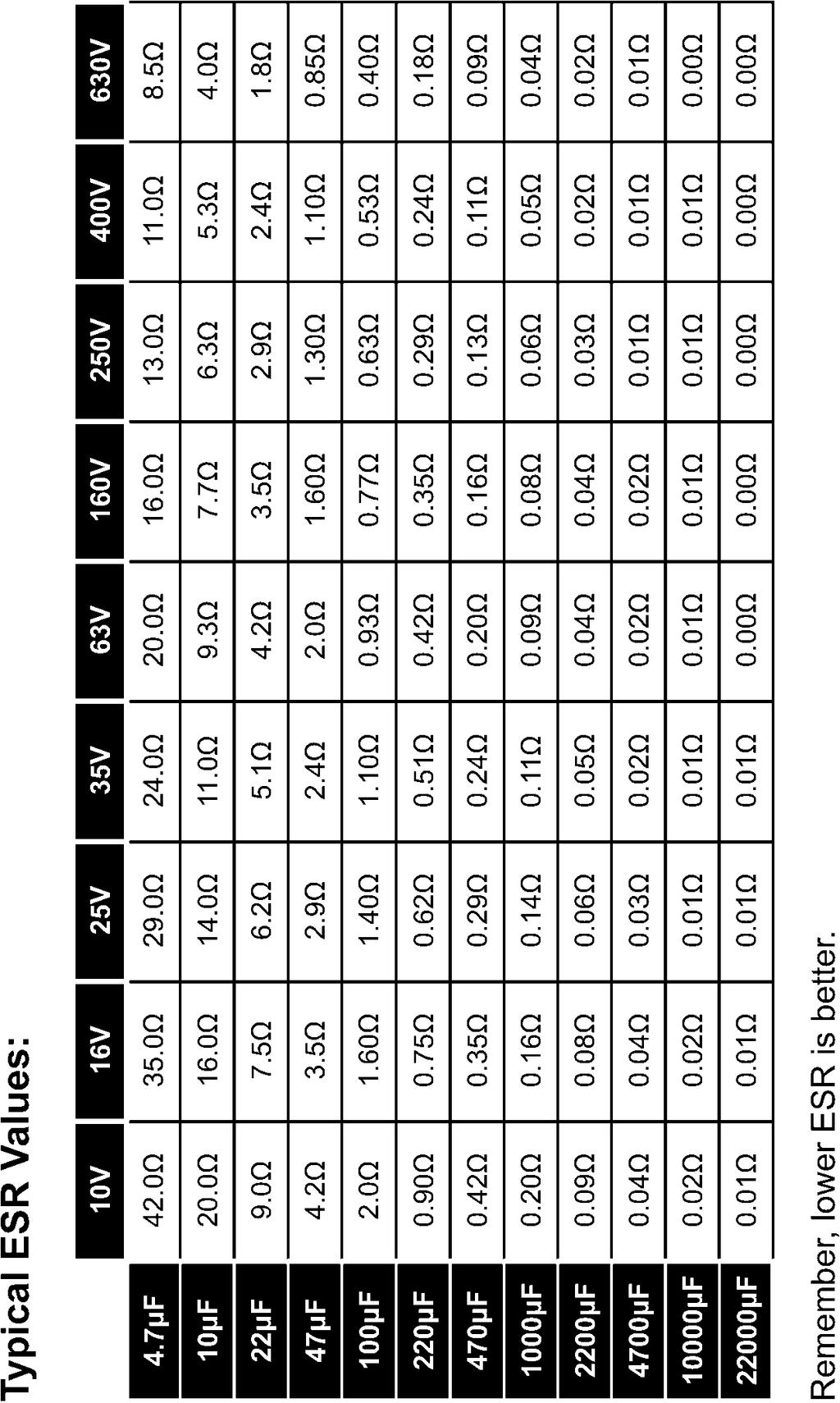
9 Page 9
10 Typical Values of ESR continued It is not possible to provide a definitive rule for values of ESR that are acceptable for all situations. However, a table of typical ESR figures for a range of capacitance and voltage ratings is shown on the previous page. The expected value of ESR largely depends on the capacitance value and the voltage rating of the capacitor but also depends on temperature ratings and other factors. Some capacitors are manufactured to exhibit very low ESR values, whilst conventional low cost parts are likely to exhibit higher values but still be acceptable. As a guide only, the following log-scaled graph shows typical values of ESR for a range of different capacitance and voltage ratings. 10 Typical ESR (Ω) V 63V 630V Capacitance(µF) Please note that the figures shown on the previous page are only typical figures for standard grade electrolytics at room temperature, please verify readings against expected values for the particular type of capacitor you are testing. For any particular capacitance and voltage rating, a lower ESR reading is generally better than a higher ESR reading. For good quality capacitors it is common for the ESR readings to be much lower than the figures shown in the previous table. Page 10
11 Audible Alerts (Model ESR70 only) The ESR70 unit can produce audible tones to assist the user. The various tones are summarised below: Condition / Operation Start Analysis End Analysis Measured ESR > 40Ω Measured ESR < 5.0Ω Measured ESR < 1.0Ω Sound Type Short Blip Short Blip High-Low Beep Barp Single Bell Ping Double Bell Ping-Ping You can switch audible alerts on or off by holding down the on-test button for about 2 seconds when powering up the unit from off. Depending on whether the sound function was already on or off, one of the following messages will be displayed to confirm that you have changed the sound mode: Sound On Sound Off Page 11
12 Probe Compensation To ensure good repeatable readings, particularly for low values of ESR, it may be necessary to occasionally perform a simple Probe Compensation procedure. This procedure is easiest to perform with the gold plated croc clips fitted. 1. Ensure the unit is switched off. 2. Press and hold down the ontest button for about 5 seconds until the following message is displayed*: 3. The unit will then ask you to short the probes together (by interlocking the jaws of each croc clip). Then press the ontest button. 4. After a short delay the display will confirm that the procedure is complete and then switch off. Probe Compensation Short probes and press TEST. OK If the following message is displayed then the probes may not have been correctly shorted during the above proecedure. This message may also be displayed if any of the probe connections are faulty. Compensation Fail. Try again. It is useful to test the integrity of the probe compensation by measuring a fixed resistor of 1Ω and 10Ω to verify the correct ESR reading respectively. * NOTE: For the ESR70, the sound on/off mode will be entered while holding the button down, keep the button held down and the unit will proceed to the probe compensation mode. Page 12
13 Care of your Atlas ESR The Peak Atlas ESR should provide many years of service if used in accordance with this user guide. Care should be taken not to expose your unit to excessive heat, shock or moisture. Additionally, the battery should be replaced at least every 12 months to reduce the risk of leak damage. ** Warning ** Low Battery If a low battery warning message appears, replacement of the battery is essential. Immediate replacement of the battery is EXTREMELY IMPORTANT as the built-in protection mechanism may not function correctly if the battery condition is poor and therefore render your unit susceptible to damage from even low energy charged capacitors. The Atlas ESR will not continue to operate if a low battery condition is encountered. New batteries can be purchased from many retailers and directly from Peak Electronic Design Ltd or an authorised agent. Battery types: Suitable battery types include 23A, V23A, GP23A, MN21 or a good quality 12V alkaline equivalent as used in many test instruments and automotive remote key fobs. Battery access: To replace the battery, unscrew the three screws to remove the rear panel. Remove the old battery and insert a new one, taking care to observe the correct polarity. Carefully replace the rear panel, do not over-tighten the screws. Page 13
14 Appendix A - Troubleshooting Problem ESR value when probes are shorted is not close to 0Ω Display shows Removing trace charge Display shows Auto discharge taking too long! Display shows Warning! V=132V Safely discharge Display shows Self Test Fail Code 2 Display shows In-Circuit/Leaky even though it s a new capacitor and out-ofcircuit. Cause / Possible Solution Perform a probe compensation. This message is displayed if the Atlas ESR has detected that the attached capacitor may be exhibiting Soakage or Dielectric Absorption, this is quite normal. The instrument then ensures that the capacitor is very well discharged and helps to prevent voltage developing across the capacitor after the normal discharge procedure has completed. The unit attempts to remove charge from the capacitor using a controlled discharge procedure. If this takes longer than 60 seconds then the discharge process will be aborted. It is recommend that you safely discharge the capacitor manually and try analysis again. If the voltage across the capacitor is greater than 50V then the Atlas ESR will not attempt to discharge the capacitor, please safely discharge the capacitor manually. It is possible that a hardware failure has occurred, please contact Peak Electronic Design Limited for assistance. The Atlas ESR will display In-Circuit/Leaky if the charge curve is non-linear by more than 10%. Some capacitors (even new ones) can exhibit a non-linear charge characteristic and means that the capacitance cannot be reliably measured. Exercising the capacitor can help, so try to measure it again a few times. Page 14
15 Appendix B - Technical Specifications All values are at 25 C unless otherwise specified. Parameter Min Typ Max Note Peak test current into S/C ±20mA ±22mA Peak test voltage, full scale ESR ±40mV ±44mV Peak test voltage across O/C ±2.5V ±3.0V Capacitance measurement range 1µF 22000µF Capacitance accuracy ±4% ±0.2µF ESR measurement range 0Ω 20Ω / 40Ω 2 ESR resolution for ESR < 2Ω 0.01Ω 0.02Ω ESR resolution for ESR > 2Ω 0.1Ω 0.2Ω ESR accuracy for ESR < 2Ω ±1.5% ±0.02Ω ESR accuracy for ESR > 2Ω ±1.5% ±0.2Ω Abuse voltage (for C < 10µF) ±275V 3 Abuse voltage (for C > 10µF) ±50V 3 Auto-Discharge voltage limit ±50V Battery type MN21/GP23A 12V Alkaline Battery voltage range 8.5V 12V Battery voltage warning threshold 8.5V Inactivity power-down period 60 seconds Dimensions (excluding test leads) 103 x 70 x 20 mm Operating temperature range 10 C 40 C 1 Notes 1. Subject to acceptable LCD visibility. 2. Model ESR70 is capable of measuring up to 40Ω. 3. Maximum abuse voltage rated limitation of internal protection electronics. Probes, leads and unit are not certified for high voltage use. Page 15

16 Appendix C Statutory Information Peak Warranty If for any reason you are not completely satisfied with the Peak Atlas ESR within 14 days of purchase you may return the unit to your distributor. You will receive a refund covering the full purchase price if the unit is returned in perfect condition. The warranty is valid for 24 months from date of purchase. This warranty covers the cost of repair or replacement due to defects in materials and/or manufacturing faults. The warranty does not cover malfunction or defects caused by: a) Operation outside the scope of the user guide. b) Unauthorised access or modification of the unit (except for battery replacement). c) Accidental physical damage or abuse. d) Normal wear and tear. The customer s statutory rights are not affected by any of the above. All claims must be accompanied by a proof of purchase. WEEE (Waste of Electrical and Electronic Equipment), Recycling of Electrical and Electronic Products In 2006 the European Union introduced regulations (WEEE) for the collection and recycling of all waste electrical and electronic equipment. It is no longer permissible to simply throw away electrical and electronic equipment. Instead, these products must enter the recycling process. Each individual EU member state has implemented the WEEE regulations into national law in slightly different ways. Please follow your national law when you want to dispose of any electrical or electronic products. More details can be obtained from your national WEEE recycling agency. At Peak Electronic Design Ltd we are committed to continual product development and improvement. The specifications of our products are therefore subject to change without notice. 2004/2016 Peak Electronic Design Limited - E&OE Designed and manufactured in the UK Tel. +44 (0) Fax. +44 (0) Page 16
Atlas ESR. User Guide. Capacitance and Equivalent Series Resistance Meter. Model ESR60 (Enhanced)
") Atlas ESR Capacitance and Equivalent Series Resistance Meter Model ESR60 (Enhanced) User Guide Peak Electronic Design Limited 2004/2008 In the interests of development, information in this guide is subject
Atlas ESR Capacitance and Equivalent Series Resistance Meter Model ESR60 (Enhanced) User Guide Peak Electronic Design Limited 2004/2008 In the interests of development, information in this guide is subject
Atlas SCR. Triac and Thyristor Analyser Model SCR100. User Guide
 GB100-5 Atlas SCR Triac and Thyristor Analyser Model SCR100 User Guide Peak Electronic Design Limited 2004/2011 In the interests of development, information in this guide is subject to change without notice
User s Manual Rev 1.3 GME
 User s Manual Rev 1.3 GME TEST INSTRUMENT SAFETY GUIDELINES WARNING An electrical shock of over 10 milliamps of current to pass through the heart will stop most human heartbeats. Voltage as low as 35 volts
1.Safe testing IMPORTANT:
 Electricity is dangerous and can cause injury and death. Always treat it with the greatest of respect and care. If you are not quite sure how to proceed, then stop, take advice from a qualified person.
ELECTRICAL. Moisture Meter User Guide
 ELECTRICAL Moisture Meter User Guide Contents 1. 2-3. Welcome Section General Information & Safety Instructions 4. 5. Contents & Features General Layout 6. 7. Setting Up Installing The Battery Turning
CONGRATULATIONS ON YOUR PURCHASE OF YOUR THUNDER BATTERY CHARGER! For your personal safety read, understand and follow the information provided in
 CONGRATULATIONS ON YOUR PURCHASE OF YOUR THUNDER BATTERY CHARGER! For your personal safety read, understand and follow the information provided in this instruction manual & on the battery charger. This
BM kv Digital Insulation Tester USER MANUAL
 M BM5200 5 kv Digital Insulation Tester USER MANUAL CONTENTS Safety warnings...3 Symbols used on instrument...4 Cleaning...4 General description...5 Insulation resistance test modes...5 Automatic discharge...5
JUMPSTART MODEL NO: JS1000, JS1010 & JS1224 OPERATING & MAINTENANCE INSTRUCTIONS PART NO: , & GC0514
 JUMPSTART MODEL NO: JS1000, JS1010 & JS1224 PART NO: 6240040, 6240035 & 6240045 OPERATING & MAINTENANCE INSTRUCTIONS GC0514 INTRODUCTION Thank you for purchasing this CLARKE Jumpstart. Before attempting
INTRODUCTION. Specifications. Operating voltage range:
 INTRODUCTION INTRODUCTION Thank you for purchasing the EcoPower Electron 65 AC Charger. This product is a fast charger with a high performance microprocessor and specialized operating software. Please
Andatech SOBERPOINT 3. Wall Mounted Breathalyser USER S MANUAL
 Andatech SOBERPOINT 3 Wall Mounted Breathalyser USER S MANUAL Thank you for purchasing an Andatech Soberpoint 3 breathalyser. The Andatech Soberpoint 3 is a Fuel Sensor type coin- or buttonoperated breathalyser.
OWNER S MANUAL Please read this manual before operating your power supply
 AC-DC POWER SUPPLY Switch Mode AC-DC Power Supply Model No. PSU-1210 PSU-1223 PSU-1230 OWNER S MANUAL Please read this manual before operating your power supply Table of Contents Precautions 2 Description
Time Electronics DC Voltage Calibrator. Technical Manual
 Time Electronics 1010 DC Voltage Calibrator Technical Manual V1.1 20/04/09 Time Electronics Ltd Botany Industrial Estate, Tonbridge, Kent, TN9 1RH Tel: +44(0)1732 355993 Fax: +44(0)1732 770312 Email: mail@timeelectronics.co.uk
ELECTRICAL. Laser Distance Measure User Guide
 ELECTRICAL Laser Distance Measure User Guide Contents 1. 2-3. Welcome Section General Information & Safety Instructions 4. 5-6. Contents & Features General Layout 7. 9-10. Setting Up Installing The Battery
MARTINDALE INSTRUCTIONS ELITE FUSE FINDER KIT ELECTRIC. Trusted by professionals. 4.4 Storage Conditions
 4.4 Storage Conditions The FD650/R and FD500/T or FD600/T should be kept in warm dry conditions away from direct sources of heat or sunlight, with the battery removed and in such a manner as to preserve
Pro Booster 802Li. Please read and fully understand the instructions in this manual before operation. Keep this manual safe for future reference.
 Please dispose of packaging for the product in a responsible manner. It is suitable for recycling. Help to protect the environment, take the packaging to the local amenity tip and place into the appropriate
C3 Operating Instructions
 Version 3.1 Stand 09.2014 Robert Bosch (Australia) Pty. Ltd. 1555 Centre Road Clayton, Victoria 3168 C3 Operating Instructions For further information please contact Bosch at: Australia 1300 30 70 40 www.boschautoparts.com.au
This manual covers the following model:
 www.skcltd.com chek-mate Air Flowmeter Operating Instructions This manual covers the following model: 375-07550 Purchase Details and Service Record Thank you for choosing an SKC product. Your purchase
MODEL No s: PP3, PP3K
 instructions for: Power PROBE 3 12-24v MODEL No s: PP3, PP3K Thank you for purchasing a Sealey product. Manufactured to a high standard this product will, if used according to these instructions and properly
BATTERY BOOSTER/CHARGER MODEL NO: DIGICAR 900
 BATTERY BOOSTER/CHARGER MODEL NO: DIGICAR 900 PART NO: 6261205 OPERATION & MAINTENANCE INSTRUCTIONS LS0715 INTRODUCTION Thank you for purchasing this CLARKE Battery booster / charger which is suitable
SWITCH-MODE CERAMIC CAPACITORS
 Switch-Mode ceramic capacitors feature large capacitance values and exhibit low ESR (equivalent series resistance) and low ESL (equivalent series inductance) making them well suited for high power and
KMP Insulation-Continuity Tester. Users Manual
 KMP 7036 Insulation-Continuity Tester Users Manual KMP7036 Insulation-Continuity Tester Users Manual English September 2011, Rev.1 2011 Amprobe Test Tools. All rights reserved. Printed in China Limited
BATTERY CHARGER-STARTER
 BATTERY CHARGER-STARTER MODEL NO: WBC240 & WBC400 PART NO: 6261505 & 6261515 OPERATION & MAINTENANCE INSTRUCTIONS GC0116 INTRODUCTION Thank you for purchasing this CLARKE Battery Charger/Starter. Please
27.6 Vdc 1 Amp Switch Mode Power Supply for Fire EN54-4:1997 +A1 +A2
 1 27.6 Vdc 1 Amp Switch Mode Power Supply for Fire EN54-4:1997 +A1 +A2 STX2401-C STX2401-T FEATURES 0843-CPR-0213 14 Elmdene International Ltd Tel: +44(0)23 9269 6638 3 Keel Close, Interchange Park, Fax:
BATTERY STARTER/CHARGER MODEL NO: BC125, BC190
 BATTERY STARTER/CHARGER MODEL NO: BC125, BC190 PART NO: 6210125, 6210200 OPERATION & MAINTENANCE INSTRUCTIONS LS0616 INTRODUCTION Thank you for purchasing this CLARKE Battery starter / charger Please read
TRICKLE CHARGER MODEL NO: ATC12VB OPERATION & MAINTENANCE INSTRUCTIONS PART NO: ORIGINAL INSTRUCTIONS LS0618 ISS 2
 TRICKLE CHARGER MODEL NO: ATC12VB PART NO: 6266012 OPERATION & MAINTENANCE INSTRUCTIONS ORIGINAL INSTRUCTIONS LS0618 ISS 2 INTRODUCTION Thank you for selecting this Clarke Trickle Charger. Read this manual
Time Electronics DC Multifunction Voltage/Current/Resistance Calibrator. Technical Manual
 Time Electronics 1017 DC Multifunction Voltage/Current/Resistance Calibrator Technical Manual V1.2 01/11/10 Time Electronics Ltd Botany Industrial Estate, Tonbridge, Kent, TN9 1RH Tel: +44(0)1732 355993
MARTINDALE MARTINDALE IN2001/IN2003 INSULATION & CONTINUITY TESTERS INSTRUCTION MANUAL IN2001/IN2003 INSULATION & CONTINUITY TESTERS
 MARTINDALE ELECTRIC Martindale Electric Company LTD Metrohm House Penfold Trading Estate Imperial Way Watford Herts WD24 4YY T: 01923 441717 F: 01923 446900 Email: sales@martindale-electric.co.uk web:
BATTERY BOOSTER/CHARGER MODEL NO: DIGICAR 600
 BATTERY BOOSTER/CHARGER MODEL NO: DIGICAR 600 PART NO: 6261200 OPERATION & MAINTENANCE INSTRUCTIONS LS0815 INTRODUCTION Thank you for purchasing this CLARKE Battery booster / charger which is suitable
LM , LM mA and 500mA Voltage Regulators
 LM2937-2.5, LM2937-3.3 400mA and 500mA Voltage Regulators General Description The LM2937-2.5 and LM2937-3.3 are positive voltage regulators capable of supplying up to 500 ma of load current. Both regulators
TESTER SET SOCKET & VOLTAGE
 SOCKET & VOLTAGE TESTER SET 82384 These instructions accompanying the product are the original instructions. This document is part of the product, keep it for the life of the product passing it on to any
Ensuring the Safety Of Medical Electronics
 Chroma Systems Solutions, Inc. Ensuring the Safety Of Medical Electronics James Richards, Marketing Engineer Keywords: 19032 Safety Analyzer, Medical Products, Ground Bond/Continuity Testing, Hipot Testing,
& HIGH CURRENT DC POWER SUPPLIES INSTRUCTION MANUAL
 72-6850 & 72-6852 HIGH CURRENT DC POWER SUPPLIES INSTRUCTION MANUAL Table of Contents Introduction 2 Specification 2 Safety 4 EMC 5 Installation 6 Connections 6 Operation 7 Maintenance and Repair 8 www.tenma.com
COMPONENT-TESTER INSTRUCTION MANUAL
 ICT76 COMPONENT-TESTER INSTRUCTION MANUAL ISO-TECH ICT 76 COMPONENT TESTER INSTRUCTION MANUAL 1 2 1. Introduction 1.1 Unpacking and checking When you unpack your new component tester, these are the items
MY /2-DIGIT DIGITAL MULTIMETER Users Manual
 MY-65 4 1/2-DIGIT DIGITAL MULTIMETER Users Manual Read the Users Manual thoroughly before use. WARRANTY This instrument is warranted to be free from defects in material and workmanship for a period of
OWNER'S MANUAL MYCRO 8
 OWNER'S MANUAL MYCRO 8 OWNER'S MANUAL MYCRO 8 Mycro Mycro Features Close tolerance and durable components provide increased reliability and greater output. Accurately machined birch plywood cabinets for
CONTENTS. Introduction. Thank you for purchasing the AlcoSense Precision+ breathalyser.
 User Manual Introduction CONTENTS Thank you for purchasing the AlcoSense Precision+ breathalyser. The AlcoSense Precision+ is certified to Australian Standard AS3547 Type 2 Quantitative Device and is one
TX900. Microwave Leakage Detector. 99 Washington Street Melrose, MA Phone Toll Free
 TX900 Microwave Leakage Detector 99 Washington Street Melrose, MA 02176 Phone 781-665-1400 Toll Free 1-800-517-8431 Visit us at www.testequipmentdepot.com Users Manual TX900 Microwave Leakage Detector
NCSA 20plus Service Manual
 Adam Equipment NCSA 20plus Service Manual (P.N. 7.00.6.6.0247- Revision A - August 2012) Adam Equipment Company 2012 1.0 CONTENTS 1.0 CONTENTS...1 1.1 KEY AND PANEL DESCRIPTION...2 2.0 OPERATION...3 2.1
Adam Equipment LHS SERIES. (P.N , Revision A March 2012)
") Adam Equipment LHS SERIES (P.N. 7.00.6.6.0200, Revision A March 2012) Adam Equipment Company 2012 1.0 CONTENTS 1.0 CONTENTS...1 2.0 INTRODUCTION...2 2.1 INTRODUCTION...2 2.2 TECHNICAL SPECIFICATIONS...3
Adam Equipment LHS SERIES (P.N. 7.00.6.6.0200, Revision A March 2012) Adam Equipment Company 2012 1.0 CONTENTS 1.0 CONTENTS...1 2.0 INTRODUCTION...2 2.1 INTRODUCTION...2 2.2 TECHNICAL SPECIFICATIONS...3
ECONOMISER SERIES E2T USER MANUAL
 TURBO S.R.L. Electronic Control Systems for Dust Collectors e-mail: info@turbocontrols.it web: www.turbocontrols.it TEL. ++39 (0)362 574024 FAX ++39 (0)362 574092 ECONOMISER SERIES E2T USER MANUAL 24/06/2014
99 Washington Street Melrose, MA Fax TestEquipmentDepot.com. Instruction Manual. Model 2831D 4 ½ Digit True RMS Digital Multimeter
 99 Washington Street Melrose, MA 02176 Fax 781-665-0780 TestEquipmentDepot.com Instruction Manual Model 2831D 4 ½ Digit True RMS Digital Multimeter 1 1. PRODUCT DESCRIPTION 1-1. Introduction Thank you
CP GermanCp 41_CP C. Operating Instructions. CP 30 CP 330 CP 1100 AC/DC current probe /7.10
 CP 30 35 GermanCp 41_CP C Operating Instructions CP 30 CP 330 CP 1100 AC/DC current probe 3-349-600-37 1/7.10 Order Reference CP 30 CP 330 CP 1100 Order No. Z201B Z202B Z203B Battery is included. Thank
with lcd display 12-42v
 instructions for: AUTO PROBE with lcd display 12-42v MODEL No: PP7 Thank you for purchasing a Sealey product. Manufactured to a high standard this product will, if used according to these instructions
LEAD ACID BATTERY CHARGER
 LEAD ACID BATTERY CHARGER MODEL NO: LA4 & LA6 OPERATION & MAINTENANCE INSTRUCTIONS LS1214 INTRODUCTION Thank you for purchasing this CLARKE Battery Charger. Please read this manual thoroughly, before attempting
RS-3 PRO RS-1007 PRO. CAT IV Analog Clamp meter Series. Users Manual. For detailed specifications and ordering info go to
 RS-3 PRO RS-1007 PRO CAT IV Analog Clamp meter Series Users Manual For detailed specifications and ordering info go to www.testequipmentdepot.com RS-3 PRO RS-1007 PRO CAT IV Analog Clampmeter Series English
LM ma Low Dropout Regulator
 500 ma Low Dropout Regulator General Description The LM2937 is a positive voltage regulator capable of supplying up to 500 ma of load current. The use of a PNP power transistor provides a low dropout voltage
LM , LM mA and 500mA Voltage Regulators
 400mA and 500mA Voltage Regulators General Description The LM2937-2.5 and LM2937-3.3 are positive voltage regulators capable of supplying up to 500 ma of load current. Both regulators are ideal for converting
R&S RT-ZC02 R&S RT-ZC03 AC/DC Current Probe User Manual
 R&S RT-ZC02 R&S RT-ZC03 AC/DC Current Probe User Manual / User Manual Content 1 Introduction 3 2 Safety 3 3 Specifications RT-ZC03 6 Specifications RT-ZC02 7 4 Operating Instructions RT-ZC03 8 Operating
KD1E Range Potential Indicators
 KD1E Range Potential Indicators Operating Instructions 99 Washington Street Melrose, MA 02176 Phone 781-665-1400 Toll Free 1-800-517-8431 Visit us at www.testequipmentdepot.com Limited Warranty & Limitation
RECHARGEABLE SPOTLIGHT
 RECHARGEABLE SPOTLIGHT MODEL: RWL10 Part No: 4002822 INSTRUCTION MANUAL LS0609 INTRODUCTION Thank you for purchasing this CLARKE product Before attempting to use the product, it is essential that you read
OPERATING INSTRUCTIONS
 OPERATING INSTRUCTIONS Digital Clamp Meter DSA500A IMPORTANT: RECEIVING INSTRUCTIONS Visually inspect all components for shipping damage. If you find damage, notify the carrier at once. Shipping damage
OPERATING INSTRUCTION
 11/05 Form #271 99 Washington Street Melrose, MA 02176 Phone 781-665-1400 Toll Free 1-800-517-8431 OPERATING INSTRUCTION Visit us at www.testequipmentdepot.com MODEL 3132 ANALOG INSULATION-CONTINUITY TESTER
Adam Equipment DUNE DCT SERIES. (P.N. 9384, Revision B2, June 2013)
") Adam Equipment DUNE DCT SERIES (P.N. 9384, Revision B2, June 2013) Adam Equipment Company 2013 Easy Reference: Model name of the scale: Serial number of the unit: Software revision number (Displayed when
Adam Equipment DUNE DCT SERIES (P.N. 9384, Revision B2, June 2013) Adam Equipment Company 2013 Easy Reference: Model name of the scale: Serial number of the unit: Software revision number (Displayed when
CAP18 CAP30. Thank you for making a your choice for car audio entertainment! 8 Farad Super Power Capacitor. 18 Farad Super Hybrid.
 CAP8 CAP18 CAP30 8 Farad Super Power Capacitor 18 Farad Super Hybrid Power Capacitor 30 Farad Super Hybrid Power Capacitor Congratulations on your purchase of a Power Capacitor System. It has been designed,
Switching DC Power Supply
 99 Washington Street Melrose, MA 02176 Phone 781-665-1400 Toll Free 1-800-517-8431 Visit us at www.testequipmentdepot.com Model 1693, 1694 Switching DC Power Supply INSTRUCTION MANUAL 1 Safety Summary
Rescue Pac. Please read and fully understand the instructions in this manual before operation. Keep this manual safe for future reference
 Please dispose of Packaging for the product in a responsible manner. It is suitable for recycling. Help to protect the environment, take the packaging to the local amenity tip and place into the appropriate
User s Manual. Automatic Switch-Mode Battery Charger
 User s Manual Automatic Switch-Mode Battery Charger IMPORTANT Read, understand, and follow these safety rules and operating instructions before using this battery charger. Only authorized and trained service
AC50A. Leakage Clamp Meter. User Manual. For detailed specifications and ordering info go to
 AC50A Leakage Clamp Meter User Manual For detailed specifications and ordering info go to www.testequipmentdepot.com Contents AC50A Current Clamp Meter Introduction... 2 Contents... 3 Transport and Storage...
NXE2 Series Isolated 2W Single Output SM DC-DC Converters
 SELECTION GUIDE NXE2 Series FEATURES Patents pending Lower Profile UL69 Recognised ANSI/AAMI ES661-1 Recognised 3kVDC Isolation Hi Pot Test Substrate Embedded Transformer Automated Manufacture Industry
SELECTION GUIDE - SINGLE OUTPUT 1. Nominal Input Voltage Output Voltage
 www.murata-ps.com SELECTION GUIDE - SINGLE OUTPUT 1 Order Code Nominal Input Voltage Output Voltage Output Current Input Current at Rated Load Load Regulation (Typ) Load Regulation (Max) Ripple & Noise
D Dräger Alcotest 3000 Breath Alcohol Measuring Device
 D Dräger Alcotest 3000 Breath Alcohol Measuring Device Instructions for Use ST-14138-2008_sw.eps Table of Contents For Your Safety....................................... 3 Intended Use..........................................
LH41A. User Manual. Clamp On Ammeter. For detailed specifications and ordering info go to
 LH41A Clamp On Ammeter User Manual For detailed specifications and ordering info go to www.testequipmentdepot.com LH41A Clamp On Ammeter Users Manual English April 2007, Rev.2 2007 Amprobe Test Tools.
OWNER'S MANUAL AIR MOTION
 OWNER'S MANUAL AIR MOTION OWNER'S MANUAL AIR MOTION Air Air Features Close tolerance and durable components provide increased reliability and greater output. High power internal crossover for easy of setup.
1 This instrument must only be used by a competent and trained person and operated in strict accordance with the instructions.
 1 This instrument must only be used by a competent and trained person and operated in strict accordance with the instructions. KYORITSU will not accept liability for any damage or injury caused by misuse
OPERATING INSTRUCTIONS
 CM OPERATING INSTRUCTIONS 9 Function, Auto Range Digital Multi-Meter DM6450 INTERTEK Read this owner s manual thoroughly before use and save. C LISTED US I. DISPLAY FUNCTIONS & SYMBOLS 9 6 10 11 14 8 7
HIGH FREQUENCY AUTOMATIC BATTERY CHARGER
 HIGH FREQUENCY AUTOMATIC BATTERY CHARGER MODEL NO: HFBC12 PART NO: 6267000 OPERATION & MAINTENANCE INSTRUCTIONS LS0814 INTRODUCTION Thank you for purchasing this CLARKE High Frequency Automatic Battery
SL101 Manual_SL101 User Manual 05/10/ :06 Page 1. Instruction Manual
 SL101 Manual_SL101 User Manual 05/10/2011 11:06 Page 1 SL101 Solar Power Irradiance Meter Instruction Manual Please read this manual before switching the unit on. Important safety information 1 inside.
Time Electronics Ins-Cal. Insulation Tester Calibration System. Technical Manual
 Time Electronics 5069 Ins-Cal Insulation Tester Calibration System Technical Manual V1.2 20/04/11 Time Electronics Ltd Botany Industrial Estate, Tonbridge, Kent, TN9 1RH Tel: +44(0)1732 355993 Fax: +44(0)1732
CONTENTS. User Safety 2 Introduction and CX440 Accessories 3 CX440 Diagram 4 CX440 Keypad and Remote Control 5 Operating Instructions 6
 CONTENTS User Safety 2 Introduction and CX440 Accessories 3 CX440 Diagram 4 CX440 Keypad and Remote Control 5 Operating Instructions 6 Batteries 6 Power and Horizontal Lines 7 Vertical Lines 8 Pulse (Outdoor)
MEE1 Series Isolated 1W Single Output DC/DC Converters
 www.murata-ps.com MEE1 Series FEATURES UL69 recognised Operation to zero load Single isolated output 1kVDC isolation Hi Pot Test Efficiency up to 87% typical Wide temperature performance at full 1 watt
Battery Charger JCB-FCH12Li
 Safety and operating manual Battery Charger JCB-FCH12Li ORIGINAL INSTRUCTIONS SAFETY INSTRUCTIONS WARNING: Read all safety warnings and all instructions.failure to follow the warnings and instructions
MOdel No: MM19.V3 WARNING CAUTION 1. SAFETY INSTRUCTIONS
 Instructions for: Digital Multimeter - 6 Function MOdel No: MM19.V3 Thank you for purchasing a Sealey product. Manufactured to a high standard this product will, if used according to these instructions
Date received into service; / /.
 Innovating Together RIGEL SafeTest 50 electrical safety analyzer Copyright 2016 SEAWARD GROUP Last Update: April 20th 2016 Instruction Manual 410A570 Revision 1.2 Limited Warranty & Limitation of Liability
80W. Operating Manual. Dual Power. Intelligent Balance Charger LiPo/LiFe/LiIon: NiMH/NiCd: Pb: Charge Power: Charge Rate: Discharge Rate:
 80W Dual Power /LiFe/LiIon NiMH/NiCd Pb Charge Power Charge Rate Discharge Rate 1-6S 1-16S 2-20V 80W 0.1-10.0A 0.1-2.0A Intelligent Balance Charger Operating Manual - 2 - Please read this operating manual
MIT300 Series Insulation and Continuity Testers
 MIT300_UG_en_V11.qxp 14/1/09 3:03 pm Page 1 M MIT300 Series Insulation and Continuity Testers Megger MIT300-EN MIT 300 EN Insulation Resistance Continuity Tester Megger MIT310A-EN MIT 310A EN Insulation
UP100AC INSTRUCTION MANUAL
 UP100AC AC/DC Charger INSTRUCTION MANUAL 100W 10A TABLE OF CONTENTS Introduction... 2 Special Features... 4 Warning and Safety Notes... 6 Lithium Battery Connection Diagram... 10 Operation Diagram - Homepage...
AMS 2000 USER GUIDE GUARDIAN INTERLOCK RESPONSIBLE DRIVER PROGRAM. GuardianInterlock.com Ensuring Safety For Over 30 Years.
 GUARDIAN INTERLOCK RESPONSIBLE DRIVER PROGRAM Ensuring Safety For Over 30 Years. GuardianInterlock.com 855-202-0080 AMS 2000 USER GUIDE GI386_REV 2017 Guardian Interlock GI559_4/17 TIME TO TEST The Guardian
Chargestar P24 / P32 Battery Charger Startmaster P300 Starter / Charger
 Please dispose of packaging for the product in a responsible manner. It is suitable for recycling. Help to protect the environment, take the packaging to the local amenity tip and place into the appropriate
Dycon D1532SM. EN50131/PD6662 Grade 3, 12V 2A Power Supply. Technical Description Installation and Operating Manual DYCON POWER SOLUTIONS LTD
 Dycon D1532SM EN50131/PD6662 Grade 3, 12V 2A Power Supply Technical Description Installation and Operating Manual DYCON POWER SOLUTIONS LTD Tel: +44 (0)1443 471 900 Unit A Cwm Cynon Business Park Mountain
SL Series Application Notes. SL Series - Application Notes. General Application Notes. Wire Gage & Distance to Load
 Transportation Products SL Series - Application Notes General Application Notes vin 2 ft. 14 AWG The SL family of power converters, designed as military grade standalone power converters, can also be used
SELECTION GUIDE. Nominal Input Voltage. Output Voltage. Input Current. Input reflected ripple current
 SELECTION GUIDE NXE2 Series FEATURES Patents pending Lower Profile UL69 Recognised ANSI/AAMI ES661-1 Recognised 3kVDC Isolation Hi Pot Test Substrate Embedded Transformer Automated Manufacture Industry
Digital/Analog Megohmmeter Model 1026 USER MANUAL
 Digital/Analog Megohmmeter Model 1026 USER MANUAL Limited Warranty The Megohmmeter Model 1026, is warranted to the owner for a period of 2 years from the date of original purchase against defects in manufacture.
INSTRUCTION MANUAL ANALOGUE INSULATION TESTER KEW 3131M KYORITSU ELECTRICAL INSTRUMENTS WORKS,LTD., TOKYO JAPAN
 INSTRUCTION MANUAL ANALOGUE INSULATION TESTER KEW 3131M KYORITSU ELECTRICAL INSTRUMENTS WORKS,LTD., TOKYO JAPAN Contents 1. Safety Precautions... 1 2. Features... 3 3. Specifications... 4 4. Instrument
BASIC ELECTRICAL MEASUREMENTS By David Navone
 BASIC ELECTRICAL MEASUREMENTS By David Navone Just about every component designed to operate in an automobile was designed to run on a nominal 12 volts. When this voltage, V, is applied across a resistance,
The 4HR-UPS 220V ac output is provided via a Pure Sine Wave inverter, allowing it to be backed up by 2x 12V standby batteries.
 1 Elmdene International Ltd Tel: +44 (0)23 9269 6638 3 Keel Close, Interchange Park, Fax: +44 (0)23 9266 0483 Portsmouth, Hampshire, PO3 5QD, UK Web: www.elmdene.co.uk STANDBY 220V AC POWER SYSTEM IDEAL
CONTACTS RELAY TESTER 66249
 RELAY TESTER 66249 These instructions accompanying the product are the original instructions. This document is part of the product, keep it for the life of the product passing it on to any subsequent holder
SELECTION GUIDE. Nominal Input Order Code Voltage. Output Voltage. Reflected ripple current
 www.murata-ps.com NML Series FEATURES RoHS compliant Single isolated output 1kVDC isolation Efficiency up to 85% Wide temperature performance at full 2 watt load, 40 C to 85 C Power density 2.01W/cm 3
IN1001/IN1003 ANALOGUE INSULATION & CONTINUITY TESTERS INSTRUCTION MANUAL IN1001/IN1003 ANALOGUE INSULATION & CONTINUITY TESTERS INSTRUCTION MANUAL
 Martindale Electric Company LTD Metrohm House Penfold Trading Estate Imperial Way Watford Herts WD24 4YY T: 01923 441717 F: 01923 446900 Email: sales@martindale-electric.co.uk web: www.martindale-electric.co.uk
Metrohm E3640 FLASH TESTER INSTRUCTION MANUAL. Martindale Electric Co Ltd.
 Metrohm Martindale Electric Metrohm House, Imperial Park, Imperial Way, Watford, Hertfordshire, WD24 4PP, UK T: 01923 441717 F: 01923 446900 Email: sales@martindale-electric.co.uk web: www.martindale-electric.co.uk
REX II Power WARRANTY REGISTRATION FORM
 REX II Power WARRANTY REGISTRATION FORM Unit Serial Number: Customer Name: Address: Date of Purchase: Purchased From: Dealer Name: Address: IMPORTANT NOTE: In order to receive the full five year product
MODEL No: TA SAFETY INSTRUCTIONS 2. FEATURES. fig.1. Original Language Version
 Instructions for: digital automotive analyser 14 function WITH IC MODEL No: TA303 Thank you for purchasing a Sealey product. Manufactured to a high standard this product will, if used according to these
SELECTION GUIDE. Order code B0303NXT-1W B0305NXT-1W B0309NXT-1W
 B-NXT-1W 1W, FIXED INPUT, ISOLATED SINGLE OUTPUT SMD DC-DC CONVERTER FEATURES Footprint over pins 1.37cm 2 Short Circuit Protection(automatic recovery) I/O isolation voltage 1000VDC Operating Temperature:
Installation and Maintenance Instructions. World Leader in Modular Torque Limiters. PTM-4 Load Monitor
 World Leader in Modular Torque Limiters Installation and Maintenance Instructions PTM-4 Load Monitor 1304 Twin Oaks Street Wichita Falls, Texas 76302 (940) 723-7800 Fax: (940) 723-7888 E-mail: sales@brunelcorp.com
User Instruction Manual Oxford Classic Digital Weigh Scale. To avoid injury, read user manual prior to use.
 User Instruction Manual Oxford Classic Digital To avoid injury, read user manual prior to use. Oxford English Contents 1. Introduction: About Your Scale... 3 2. Assembly and Commissioning Instructions...
Digital Multimeter: This handheld device is used by this course to measure voltage and resistance we will not use this to measure current or capacitan
 Digital Multimeter: This handheld device is used by this course to measure voltage and resistance we will not use this to measure current or capacitance. For current you will use an analog ammeter and
(typ.) (Range) Input Specifications Parameter Model Min. Typ. Max. Unit 12V Input Models Input Surge Voltage (100ms.
 (Range) Input Specifications Parameter Model Min. Typ. Max. Unit 12V Input Models Input Surge Voltage (100ms.") FEATURES Smallest Encapsulated 50W! Package Size 2.0 x 1.0 x 0.4 Wide 2:1 lnput Range Excellent Efficiency up to 92% Over-Temperature Protection I/O-isolation Voltage 1500VDC Remote On/Off Control Shielded
FEATURES Smallest Encapsulated 50W! Package Size 2.0 x 1.0 x 0.4 Wide 2:1 lnput Range Excellent Efficiency up to 92% Over-Temperature Protection I/O-isolation Voltage 1500VDC Remote On/Off Control Shielded
SI AT A22. English. Printed: Doc-Nr: PUB / / 000 / 01
 SI AT A22 English 1 Information about the documentation 1.1 About this documentation Read this documentation before initial operation or use. This is a prerequisite for safe, trouble-free handling and
SELECTION GUIDE. Nominal Input Voltage. Output Voltage. Input Current. Input reflected ripple current
 SELECTION GUIDE FEATURES Patents pending Lower Profile UL9 Recognised ANSI/AAMI ES1-1 Recognised 3kVDC Isolation Hi Pot Test Substrate Embedded Transformer Automated Manufacture Industry Standard Footprint
Silvertel. Ag Features. Multi-Stage Charging. Battery Reversal Protection. Reduced Power Consumption. Wide DC or AC Input Voltage Range
 Silvertel V1.3 October 2009 Datasheet Intelligent Pb 1 Features Multi-Stage Charging Battery Reversal Protection Reduced Power Consumption Wide DC or AC Input Voltage Range High Efficiency DC-DC Converter
CONTENTS. Calibration Self Check & Technical Specifications 13 Care & Maintenance, Trouble Shooting 15 Warranty 16
 CONTENTS User Safety 2 Introduction and 3L360 Accessories 3 3L360 Diagram 4 Operating Instructions 7 Batteries 7 Power 8 Manual Mode. 9 Pulse Mode 10 LLR705 Receiver (optional 3L360R only) 11 Mounting