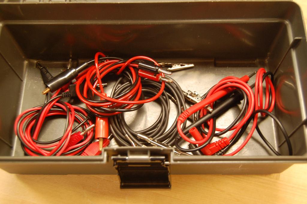
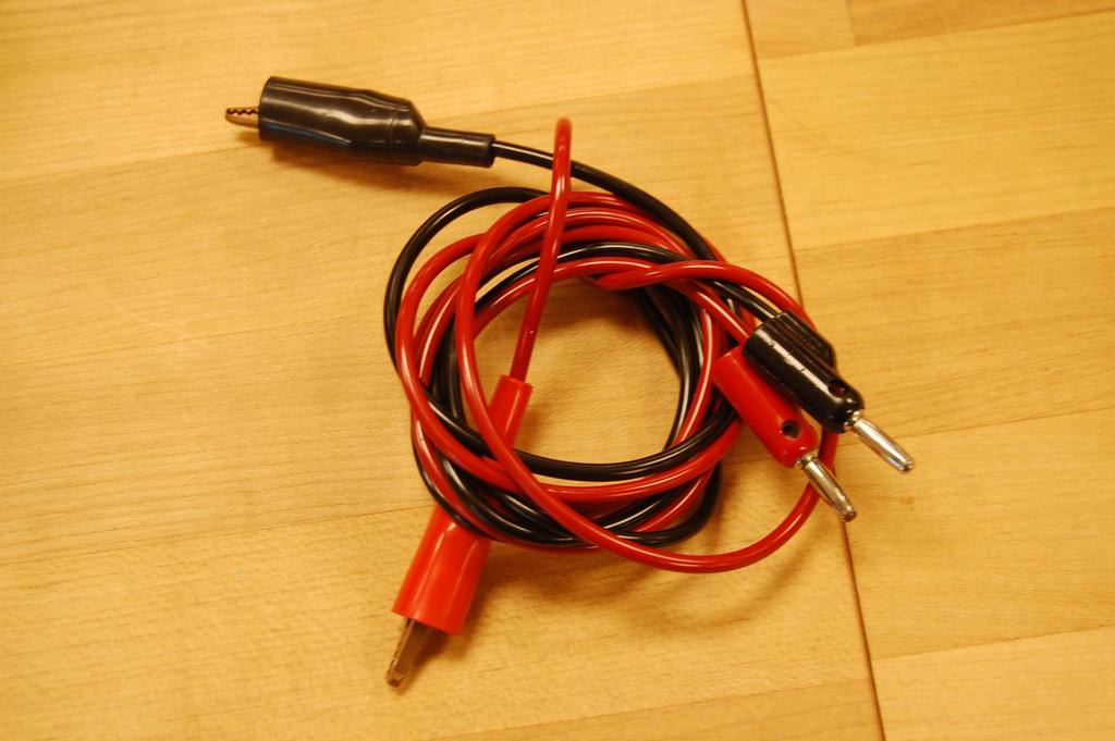
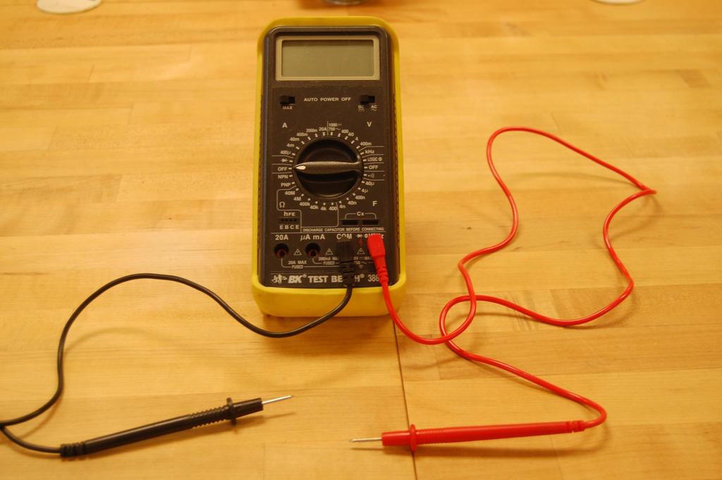
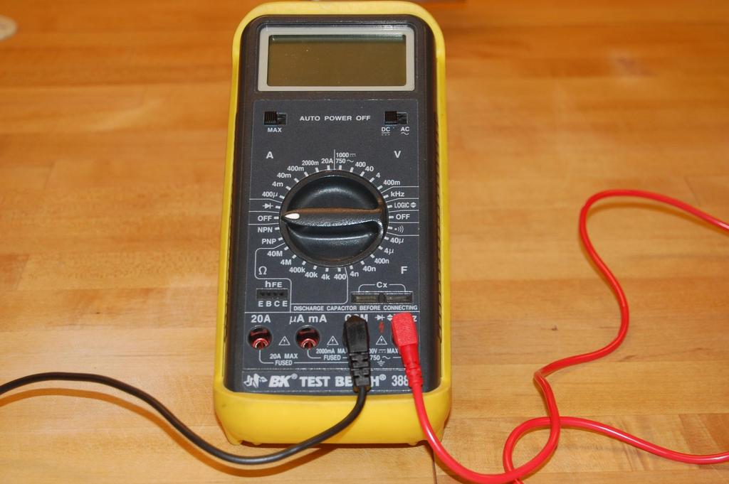
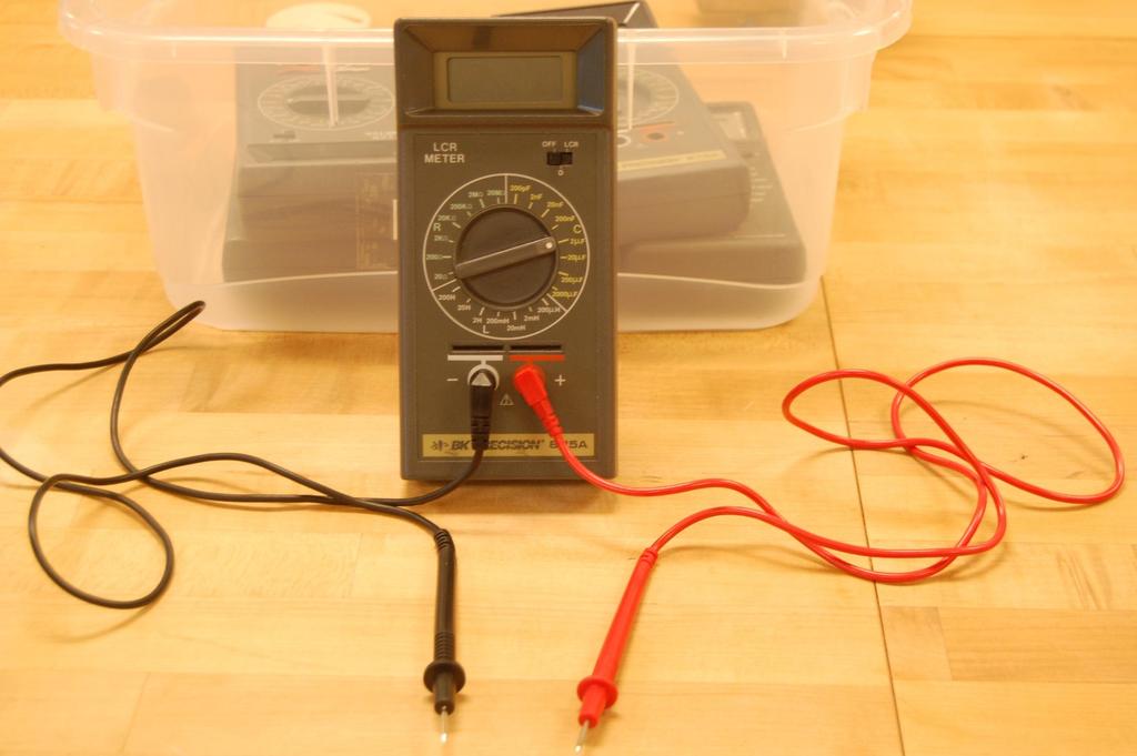
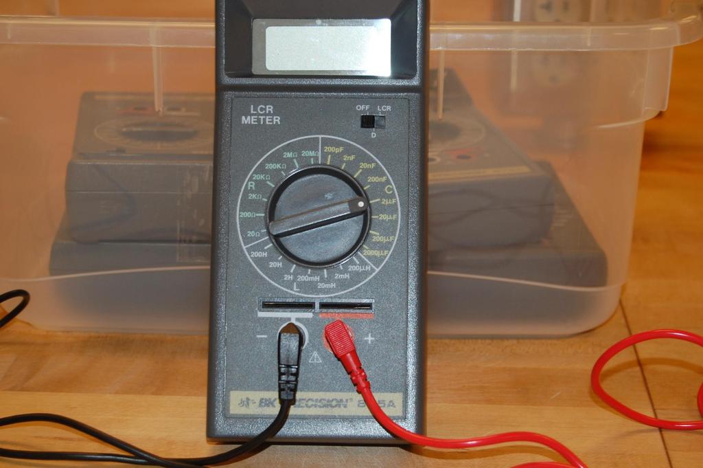
Digital Multimeter: This handheld device is used by this course to measure voltage and resistance we will not use this to measure current or capacitan
|
|
|
- Homer Blake
- 5 years ago
- Views:
Transcription
1
2
3
4
5
6
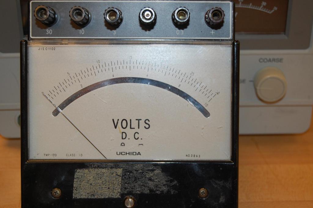
7 Digital Multimeter: This handheld device is used by this course to measure voltage and resistance we will not use this to measure current or capacitance. For current you will use an analog ammeter and for capacitance you will use a separate LCR meter. A R V C A COM V, black red
8 a) For the labs in this class you will be using DC (Direct Current) circuits, so make sure the meters are switched to DC mode. b) The Red probe goes in the red hole on the bottom right labeled (V,Ω) and the black probe goes into the next hole labeled com. In the voltage mode, the meter reads the potential of the red probe relative to the black probe. c) The values indicated on the settings are the maximum measurable values for this setting, if you get an OL response, it means you are out of range and you need to use a higher setting. Typically you want to use the lowest permissible setting to get the maximum precision for the instrument. d) In many of these DMM s, the lowest resistance setting also beeps indicating there is continuity, sometimes a useful piece of information, but the beeping can sometimes be irritating. e) To measure low resistances, you must touch the ends of the probes together to measure the internal: resistance this must be subtracted off any measured small resistance to take the internal resistance into account.
9
10
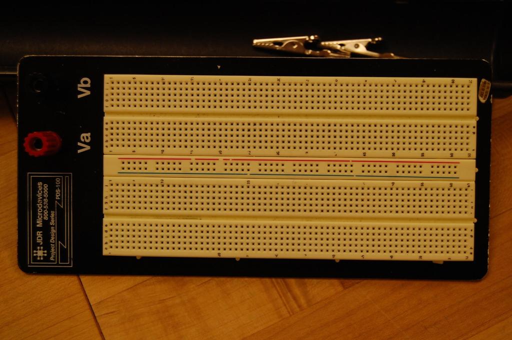
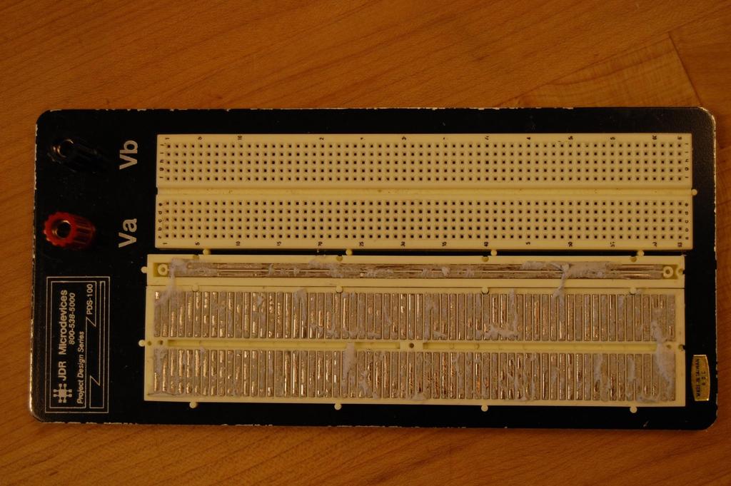
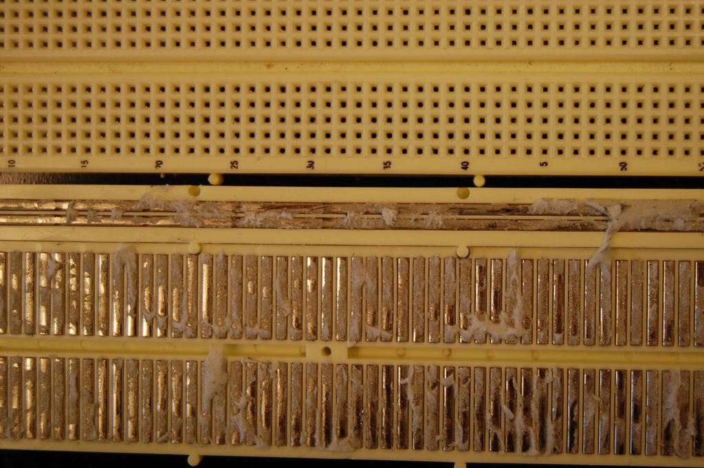
11
12
13
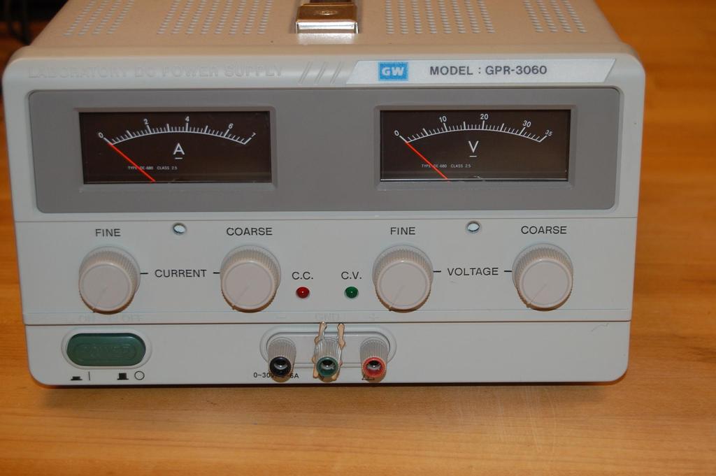
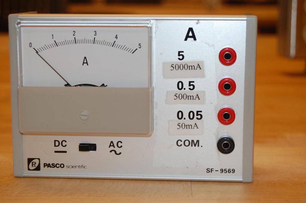
14 Power Supply: The power supply delivers current as a result of applied voltage, a properly working supply will show a green light. If the light turns red, you will have to increase the current setting. Power = current x voltage. The Red output = positive (+) terminal The Black output = negative (-) terminal The Green output = ground The current and voltage settings have a coarse and fine control current voltage F C F C on/off - + B G R
15
16 Proper operation: i) turn all the dials to zero initially, then ii) adjust the coarse CURRENT setting about half maximum, then iii) adjust the voltage to the desired current or voltage value. You can increase voltage until you reach your pre-set current value (P = I x V), to get more voltage (or more power) you will have to increase the current setting
17
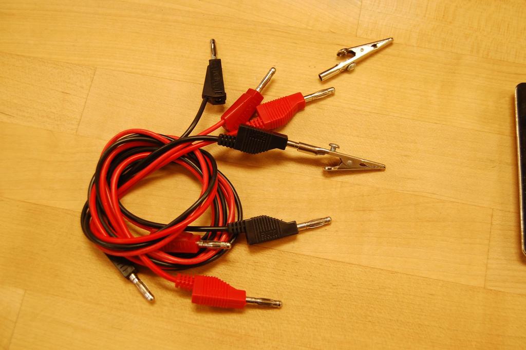
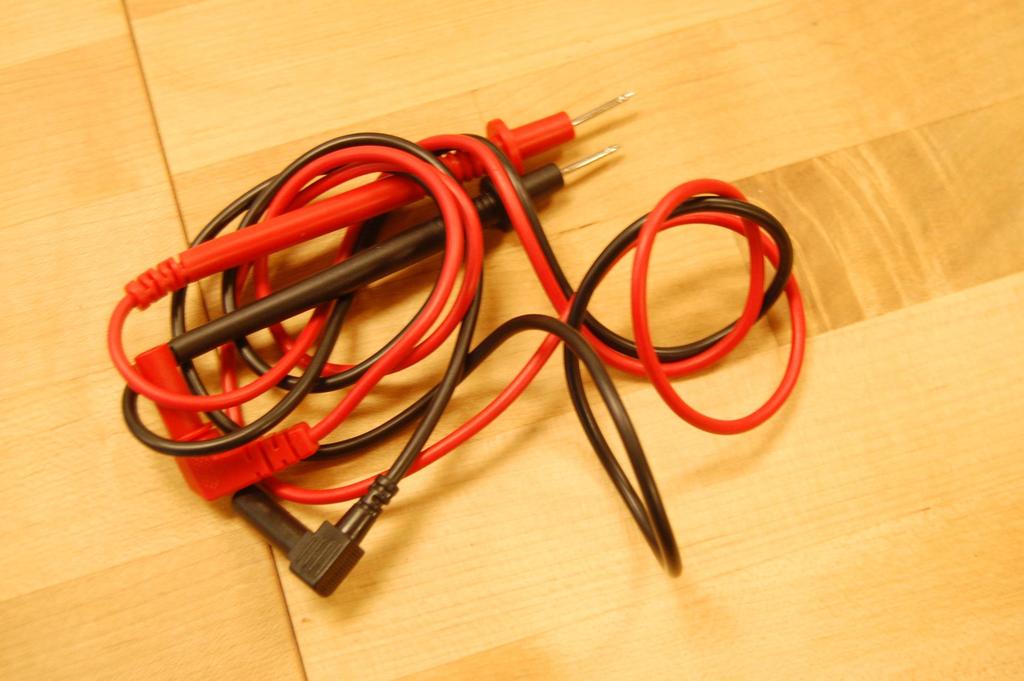
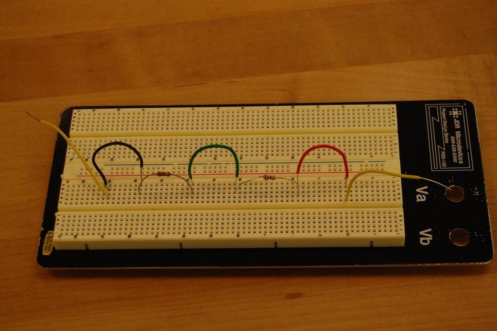
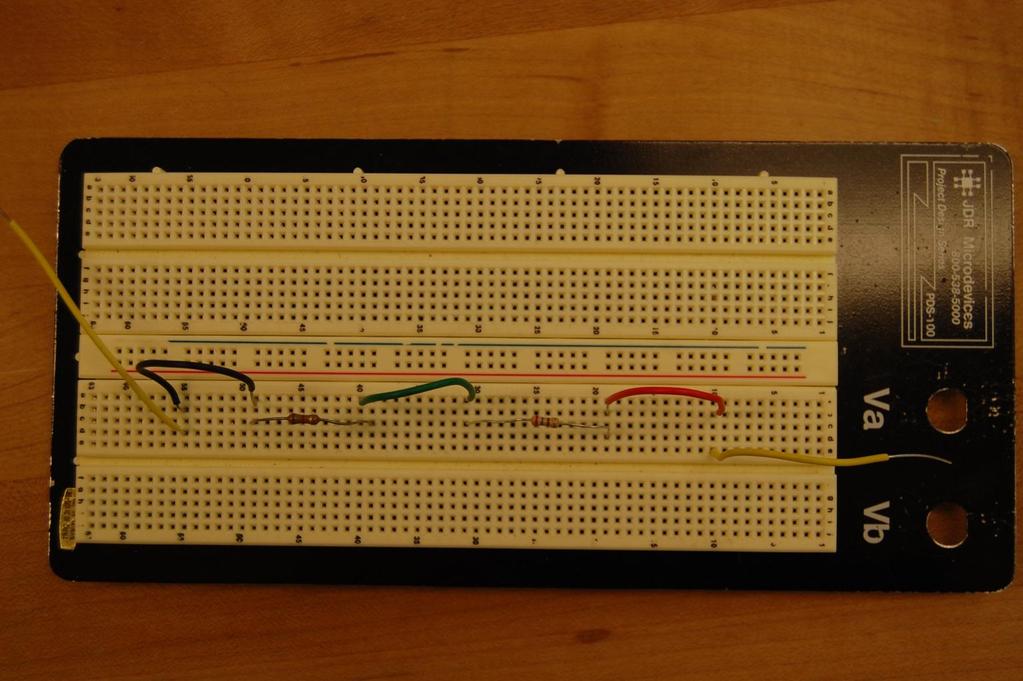
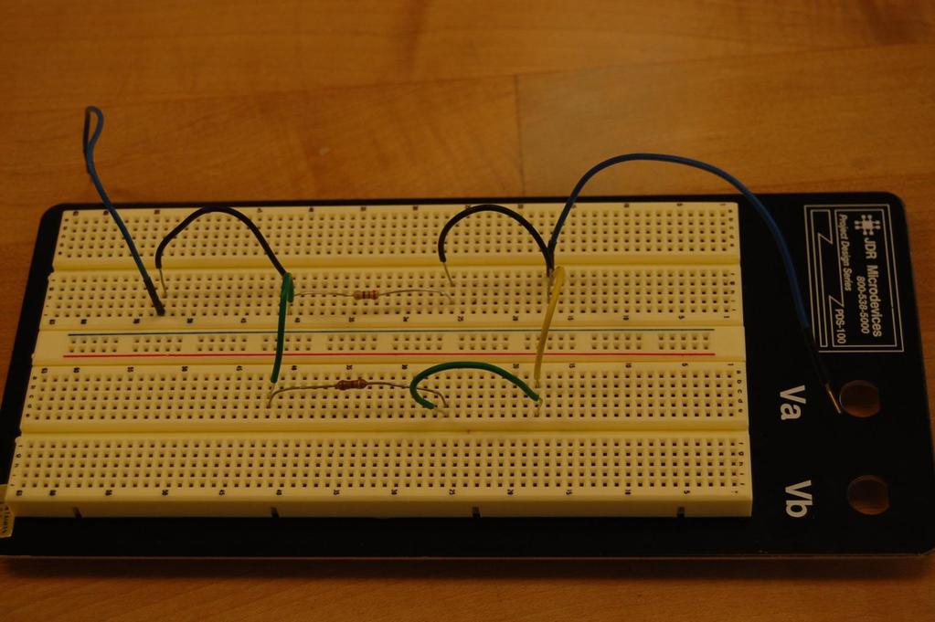
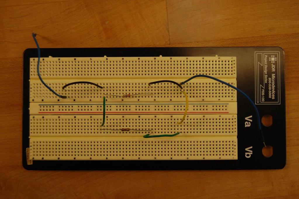
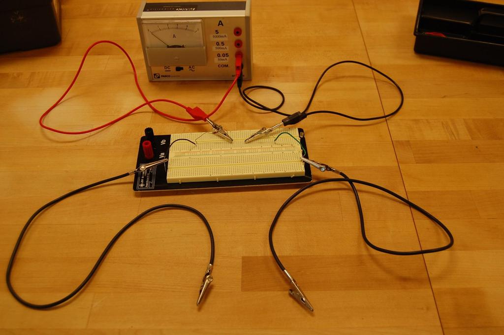
18 3. Breadboard Many times you will be assembling components together on a breadboard. This is a device specifically designed for plugging components together WE WILL NOT BE TWISTING WIRES TOGETHER!! There are several rows of holes. Each group of 5 holes are connected together with a copper strip, thereby creating a conductive path between the 5 holes.
19
20
21
22 To ensure the components are connected together, make sure the connected components lie in the same column of 5 holes. The red and black banana connectors on the side are not connected to anything on the breadboard turn the breadboard upside down and you will see. If you want to attach power there, you need to also attach jumper wires from the banana plugs to the breadboard or just connect directly to the breadboard. Jumper wires (short insulated wires that are stripped at the ends) can also be used to connect components from one part of the breadboard to other parts. When components are assembled on the breadboard, you cannot directly measure the value of that component (resistor or capacitor) as your measurement will measure the equivalent value between the two probes in all cases. obviously there will be some times that such a measurement is OK, but in most cases it is not so don t start bad habits!
23
24 Exercise: Using the DMM, set to measure up to 4.00 volts, put the red probe in the red output and the black probe in the black output. Using the technique above for proper operation,set the voltage to show 4.00 volts on the DMM the meter should show (+) 4.00 and the conventional current is flowing from Red-to-Black between the probes. If you reverse the probes, red probe in the black output and black probe in the red output, the meter should show (- 4.00). So when properly set up, the voltage sign will tell you which way the conventional current is flowing positive potential difference means conventional current flows between the probes, Red-to-Black. Series and Parallel: series R1 R2 current parallel R1 R2
25
26
27 a) In series, both resistors should have the same current and their voltages add together. b) In parallel, both resistors have the same voltage drop and the incoming current divides between the two such that the voltages are equal. i current R1 R2 i1 i2 Such that V1 = V2 = i1 R1 = i2 R2 c) Verify these two conditions
28
29
30
31
32 For series: 1. Apply 4.00 volts to the series combination 2. Measure: V1 = V2 = V1+V2 = Using the ammeter, measure first incoming current: i = Then measure i1 = i2 = Predict i1 and i2: I = V/R, i1 = V1/R1 and i2 = V2/R2 i1 = i2 =, the two sets of values should be equal
33 A i R1 R2 current R1 i1 A R2 R1 R2 i2 A
34 3. For the parallel combination:, again apply the 4.00 volts. 4. Measure: V1 = V2 = Using the ammeter, measure first incoming current: i =
35 i R1 A R2 R1 i1 A R2 R1 R2 A i2 Then reconnect the ammeter as shown and measure: i1 = i2 =, sum the two: i1+i2 = and the sum should equal i from above (or at least be close, since the ammeters provide a little resistance to the circuit.
36
37
38
Experiment 1 Breadboard Basics
 Experiment 1 Breadboard Basics The goal of Experiment 1 is for you to identify on the breadboard of the ANDY board: which of the rows of pins are connected (shorted) together and which of the set of pins
CHAPTER 2. Current and Voltage
 CHAPTER 2 Current and Voltage The primary objective of this laboratory exercise is to familiarize the reader with two common laboratory instruments that will be used throughout the rest of this text. In
Exercise 2: Series-Opposing DC Sources
 Exercise 2: Series-Opposing DC Sources EXERCISE OBJECTIVE When you have completed this exercise, you will be able to determine voltage by using series-opposing power connections. You will verify your results
LAB 7. SERIES AND PARALLEL RESISTORS
 Name: LAB 7. SERIES AND PARALLEL RESISTORS Problem How do you measure resistance, voltage, and current in a resistor? How are these quantities related? What is the difference between a series circuit and
SC10F Circuits Lab Name:
 SC10F Circuits Lab Name: Purpose: In this lab you will be making, both, series and parallel circuits. You will then be using a millimeter to take readings at various points in these circuits. Using these
Experiment 3: Ohm s Law; Electric Power. Don t take circuits apart until the instructor says you don't need to double-check anything.
 Experiment 3: Ohm s Law; Electric Power. How to use the digital meters: You have already used these for DC volts; turn the dial to "DCA" instead to get DC amps. If the meter has more than two connectors,
Lecture PowerPoints. Chapter 19 Physics: Principles with Applications, 6 th edition Giancoli
 Lecture PowerPoints Chapter 19 Physics: Principles with Applications, 6 th edition Giancoli 2005 Pearson Prentice Hall This work is protected by United States copyright laws and is provided solely for
Series and Parallel Networks
 Series and Parallel Networks Department of Physics & Astronomy Texas Christian University, Fort Worth, TX January 17, 2014 1 Introduction In this experiment you will examine the brightness of light bulbs
Physics Experiment 9 Ohm s Law
 Fig. 9-1 Simple Series Circuit Equipment: Universal Circuit Board Power Supply 2 DMM's (Digital Multi-Meters) with Leads 150- Resistor 330- Resistor 560- Resistor Unknown Resistor Miniature Light Bulb
Lab 2 Electrical Measurements and Ohm s Law
 Lab 2 Electrical Measurements and Ohm s Law Safety and Equipment No special safety precautions are necessary for this lab. Computer with PASCO Capstone, PASCO 850 Universal Interface Double banana/alligator
General Electrical Information
 Memorial University of Newfoundland Department of Physics and Physical Oceanography Physics 2055 Laboratory General Electrical Information Breadboards The name breadboard comes from the days when electrical
AP Physics B Ch 18 and 19 Ohm's Law and Circuits
 Name: Period: Date: AP Physics B Ch 18 and 19 Ohm's Law and Circuits MULTIPLE CHOICE. Choose the one alternative that best completes the statement or answers the question. 1) A device that produces electricity
Laboratory 2 Electronics Engineering 1270
 Laboratory 2 Electronics Engineering 1270 DC Test Equipment Purpose: This lab will introduce many of the fundamental test equipment and procedures used for verifying the operations of electrical circuits.
#180 LOADpro OPERATING MANUAL
 April 2011 Version 1.2 Protected by U.S. Patent 6,356,853 EU Patent 1,203,202 Japan Patent Pending Caterpillar P/N 275-9936 UPS P/N 3023348 Volvo P/N 85107792 #180 LOADpro OPERATING MANUAL Watch our product
PHYSICS 111 LABORATORY Experiment #3 Current, Voltage and Resistance in Series and Parallel Circuits
 PHYSCS 111 LABORATORY Experiment #3 Current, Voltage and Resistance in Series and Parallel Circuits This experiment is designed to investigate the relationship between current and potential in simple series
Electronics Technology and Robotics I Week 2 Basic Electrical Meters and Ohm s Law
 Electronics Technology and Robotics I Week 2 Basic Electrical Meters and Ohm s Law Administration: o Prayer o Bible Verse o Turn in quiz Meters: o Terms and Definitions: Analog vs. Digital Displays: Analog
COLLEGE PHYSICS Chapter 21 CIRCUITS, BIOELECTRICITY, AND DC INSTRUMENTS
 COLLEGE PHYSICS Chapter 21 CIRCUITS, BIOELECTRICITY, AND DC INSTRUMENTS Resistances in Series, Parallel, and Series Parallel Combinations Resistors in series all have the same current. Resistances in Series,
This appendix gives you a general introduction to what electricity is
 C5865_App B_CTP.qxd 24/09/2006 01:50 PM Page 1215 APPENDIX B Electricity and Multimeters This appendix gives you a general introduction to what electricity is and how it is measured. In addition, you will
Building an Electric Circuit to Convert the Sensor Resistance into a Usable Voltage INSTRUCTIONS
 Building an Electric Circuit to Convert the Sensor Resistance into a Usable Voltage INSTRUCTIONS Use this instruction manual to help you build an electric circuit to convert the sensor resistance into
Lab 4.4 Arduino Microcontroller, Resistors, and Simple Circuits
 Lab 4.4 Arduino Microcontroller, Resistors, and Simple Circuits A microcontroller is a "brain" of a mechatronic system that interfaces sensors with a computer. Microcontrollers can perform math operations,
Circuits. What are circuits?
 Circuits Circuits What are circuits? A closed loop made of a conducting substance that allows electrons to flow from the negative terminal to the positive terminal Parts of a Circuit 1 Power Supply Provides
Figure 1: (a) cables with alligator clips and (b) cables with banana plugs.
 cables with alligator clips and (b) cables with banana plugs.") Ohm s Law Safety and Equipment Computer with PASCO Capstone, PASCO 850 Universal Interface Double banana/alligator Cable, 2 Alligator Wires PASCO Voltage Sensor Cable Multimeter with probes. Rheostat Ruler
Ohm s Law Safety and Equipment Computer with PASCO Capstone, PASCO 850 Universal Interface Double banana/alligator Cable, 2 Alligator Wires PASCO Voltage Sensor Cable Multimeter with probes. Rheostat Ruler
Lab #1: Electrical Measurements I Resistance
 Lab #: Electrical Measurements I esistance Goal: Learn to measure basic electrical quantities; study the effect of measurement apparatus on the quantities being measured by investigating the internal resistances
HOW TO USE A MULTIMETER, PART 1: INTRODUCTION
 HOW TO USE A MULTIMETER, PART 1: INTRODUCTION By: Rob Siegel First, thanks for all the comments, both here and on my Facebook page, about the piece on Electrical Safety two weeks ago. I felt that, if I
PARTS LIST. Beams: 72x. 16x. 64x. 16x. 12x. 2x Breadboards CYB x TotemDuino 1x LabBoard 1x 30cm 34way Flat Cable 1x Power Supply 12v 1,5A
 Totem Mini Lab is a great platform to experiment, learn basics of electronics and Arduino coding. We have made an all-in-one breadboarding and testing unit, that gives you several useful features: Different
Batteries n Bulbs: Voltage, Current and Resistance (8/6/15) (approx. 2h)
 (approx. 2h)") Batteries n Bulbs: Voltage, Current and Resistance (8/6/15) (approx. 2h) Introduction A simple electric circuit can be made from a voltage source (batteries), wires through which current flows and a resistance,
Batteries n Bulbs: Voltage, Current and Resistance (8/6/15) (approx. 2h) Introduction A simple electric circuit can be made from a voltage source (batteries), wires through which current flows and a resistance,
Investigation Electrical Circuits
 ACTIVITY #1 Task: To design and construct a circuit where 2 light bulbs can turn on and off at the same time Materials: - 1 power supply - 2 light bulbs - Connecting wires ( ) - Switch(s) - Multi-meter
UNIT 3: GENErAL ELECTriCAL SySTEM DiAGNOSiS
 Electrical/Electronic Systems UNIT 3: GENErAL ELECTriCAL SySTEM DiAGNOSiS LESSON 3: TEST electrical circuits I. Types of electrical circuit tests and electrical faults A. Different types of electrical
Digital Multimeter AHMAD FOUAD ALWAN
 Digital Multimeter AHMAD FOUAD ALWAN What is a Digital Multimeter? Test leads are used to connect the multimeter to the circuit to be tested. 1. To know how to use the Ammeter and how to read the measure.
Laboratory 5: Electric Circuits Prelab
 Phys 132L Fall 2018 Laboratory 5: Electric Circuits Prelab 1 Current and moving charges Atypical currentinanelectronic devicemightbe5.0 10 3 A.Determinethenumber of electrons that pass through the device
Current Electricity. GRADE 10 PHYSICAL SCIENCE Robyn Basson CAPS
 Current Electricity GRADE 10 PHYSICAL SCIENCE Robyn Basson CAPS What is current electricity? The flow of moving charge, usually carried by moving electrons in a wire. Circuits A path in which charges continually
Chapter 3. ECE Tools and Concepts
 Chapter 3 ECE Tools and Concepts 31 CHAPTER 3. ECE TOOLS AND CONCEPTS 3.1 Section Overview This section has four exercises. Each exercise uses a prototyping board for building the circuits. Understanding
EXPERIMENT 4 OHM S LAW, RESISTORS IN SERIES AND PARALLEL
 220 4- I. THEOY EXPEIMENT 4 OHM S LAW, ESISTOS IN SEIES AND PAALLEL The purposes of this experiment are to test Ohm's Law, to study resistors in series and parallel, and to learn the correct use of ammeters
Getting Started with the Digilent Electronics Explorer Board
 Getting Started with the Digilent Electronics Explorer Board This tutorial provides a very basic overview of the Digilent Electronics Explorer (EE) Board. 1. EE Board Physical Description A top view of
Series and Parallel Circuits
 Series and Parallel Circuits 1 of 23 Boardworks Ltd 2016 Series and Parallel Circuits 2 of 23 Boardworks Ltd 2016 What are series and parallel circuits? 3 of 23 Boardworks Ltd 2016 Circuit components can
11.1 CURRENT ELECTRICITY. Electrochemical Cells (the energy source) pg Wet Cell. Dry Cell. Positive. Terminal. Negative.
 pg Wet Cell. Dry Cell. Positive. Terminal. Negative.") Date: SNC1D: Electricity 11.1 CURRENT ELECTRICITY Define: CIRCUIT: path that electrons follow. CURRENT ELECTRICITY: continuous flow of electrons in a circuit LOAD: device that converts electrical energy
Date: SNC1D: Electricity 11.1 CURRENT ELECTRICITY Define: CIRCUIT: path that electrons follow. CURRENT ELECTRICITY: continuous flow of electrons in a circuit LOAD: device that converts electrical energy
Electrical Service & Diagnosis. ATASA 5 th. ATASA 5 TH Study Guide Chapter 16 Pages Electrical Service & Diagnosis 70 Points
 ATASA 5 TH Study Guide Chapter 16 Pages 457 500 70 Points Please Read the Summary 1. All Electrical problems can be categorized into one of three categories: Open Consumer Opens Shorts Open Conductive
PAGE Both power cords must be connected & powered to operate the E-TES 120.
 PAGE 1 This document outlines questions to ask and components to check during E-TES 120 troubleshooting. More detailed troubleshooting procedures are available in the E-TES 120 Troubleshooting Guide. 1.
Technical Workshop: Electrical December 3, 2016
 Technical Workshop: Electrical December 3, 2016 ELECTRICAL: CIRCUITS Key terms we will be using today: Voltage (V): The difference in electrical potential at one point in a circuit in relation to another.
Chapter 9 Basic meters
 Chapter 9 Basic meters Core Competency Units UEENEEE003B Solve problems in extra-low voltage single path circuits UEENEEE004B Solve problems in multiple path DC Circuits Essential Knowledge and Associated
PHY152H1S Practical 3: Introduction to Circuits
 PHY152H1S Practical 3: Introduction to Circuits Don t forget: List the NAMES of all participants on the first page of each day s write-up. Note if any participants arrived late or left early. Put the DATE
Happy Friday! Do this now:
 Happy Friday! Do this now: Take all three AA batteries out of your kit, and put (only!) two of them in the holder. (Keep the third one handy.) Take your digital multimeter out of its packaging, as well
Basic Circuits Notes- THEORY. An electrical circuit is a closed loop conducting path in which electrical current flows
 Basic Circuits Notes- THEORY NAME: An electrical circuit is a closed loop conducting path in which electrical current flows Now how does a circuit work? In order to get the water flowing, you d need a
INVESTIGATION ONE: WHAT DOES A VOLTMETER DO? How Are Values of Circuit Variables Measured?
 How Are Values of Circuit Variables Measured? INTRODUCTION People who use electric circuits for practical purposes often need to measure quantitative values of electric pressure difference and flow rate
CHAPTER 19 DC Circuits Units
 CHAPTER 19 DC Circuits Units EMF and Terminal Voltage Resistors in Series and in Parallel Kirchhoff s Rules EMFs in Series and in Parallel; Charging a Battery Circuits Containing Capacitors in Series and
34.5 Electric Current: Ohm s Law OHM, OHM ON THE RANGE. Purpose. Required Equipment and Supplies. Discussion. Procedure
 Name Period Date CONCEPTUAL PHYSICS Experiment 34.5 Electric : Ohm s Law OHM, OHM ON THE RANGE Thanx to Dean Baird Purpose In this experiment, you will arrange a simple circuit involving a power source
Lecture 5, 7/19/2017. Review: Kirchhoff s Rules Capacitors in series and in parallel. Charging/Discharging capacitors. Magnetism
 Lecture 5, 7/19/2017 Review: Kirchhoff s Rules Capacitors in series and in parallel. Charging/Discharging capacitors. Magnetism Find the current drawn by this circuit. Kirchhoff s Rules Kirchhoff s rules:
PHY222 Lab 4 Ohm s Law and Electric Circuits Ohm s Law; Series Resistors; Circuits Inside Three- and Four-Terminal Black Boxes
 PHY222 Lab 4 Ohm s Law and Electric Circuits Ohm s Law; Series Resistors; Circuits Inside Three- and Four-Terminal Black Boxes Print Your Name Print Your Partners' Names Instructions February 8, 2017 Before
Atlas ESR and ESR + Equivalent Series Resistance and Capacitance Meter. Model ESR60/ESR70. Designed and manufactured with pride in the UK.
 GB60/70-9 Atlas ESR and ESR + Equivalent Series Resistance and Capacitance Meter Model ESR60/ESR70 Designed and manufactured with pride in the UK User Guide Peak Electronic Design Limited 2004/2016 In
Reproduction or other use of this Manual, without the express written consent of Vulcan, is prohibited.
 SERVICE MANUAL ELECTRIC BRAISING PANS (30 & 40 GALLON) VE30 VE40 ML-126849 ML-126850 VE40 SHOWN - NOTICE - This Manual is prepared for the use of trained Vulcan Service Technicians and should not be used
Mandatory Experiment: Electric conduction
 Name: Class: Mandatory Experiment: Electric conduction In this experiment, you will investigate how different materials affect the brightness of a bulb in a simple electric circuit. 1. Take a battery holder,
Handyman Motor Capacitor Meter PART NO
 Handyman Motor Capacitor Meter PART NO. 2225174 To test a motor-run capacitor in the field with no capacitance meter at hand, you had to hook up the capacitor through an extension cable to a 120V wall
Chapter 28. Direct Current Circuits
 Chapter 28 Direct Current Circuits Direct Current When the current in a circuit has a constant magnitude and direction, the current is called direct current Because the potential difference between the
Phase 1 Workshop Home Study Guide
 Phase 1 Workshop Home Study Guide Vehicle Electrical-Electronics Troubleshooting Training Written and Developed by Vince Fischelli Director of Training Veejer Enterprises Inc. / Garland, Texas U.S.A. Phone:
PHY132 Practicals Week 5 Student Guide
 PHY132 Practicals Week 5 Student Guide Concepts of this Module Introducing current and voltage Simple circuits Circuit diagrams Background When water flows through a garden hose, we can characterize the
Equivalent Meter Resistance
 Equivalent Meter Resistance This installation of N.E.R.D discusses meter resistance. The equipment referenced here is found in the Undergraduate Electronics Lab at the University of Houston. Topics covered
Direct-Current Circuits
 Chapter 26 Direct-Current Circuits PowerPoint Lectures for University Physics, 14th Edition Hugh D. Young and Roger A. Freedman Lectures by Jason Harlow Learning Goals for Chapter 26 Looking forward at
Science Olympiad Shock Value ~ Basic Circuits and Schematics
 Science Olympiad Shock Value ~ Basic Circuits and Schematics Use a single D battery, a single bare wire and a light bulb. Find four different ways to light the light bulb using only a battery, one wire
MATE Triggerfish Trouble Shooting the Sabertooth 2X5 Motor Controller
 MATE Triggerfish Trouble Shooting the Sabertooth 2X5 Motor Controller Sabertooth Documentation The Sabertooth 2X5 motor controller is used on the MATE Triggerfish ROV kit and has shown to be very reliable,
Period 11 Activity Sheet Solutions: Electric Current
 Period 11 Activity Sheet Solutions: Electric Current Activity 11.1: How Can Electric Charge Do Work? Your instructor will demonstrate a Wimshurst machine, which separates electric charge. a) Describe what
A device that measures the current in a circuit. It is always connected in SERIES to the device through which it is measuring current.
 Goals of this second circuit lab packet: 1 to learn to use voltmeters an ammeters, the basic devices for analyzing a circuit. 2 to learn to use two devices which make circuit building far more simple:
Name Period. (c) Now replace the round bulb(s) with long bulb(s). How does the brightness change?
 Now replace the round bulb(s) with long bulb(s). How does the brightness change?") Name Period P Phys 1 Discovery Lesson Electric Circuits 2.1 Experiment: Charge Flow Strength & Resistors circuit is an unbroken loop of conductors. Charge (q) can flow continuously in a circuit. If an
Name Period P Phys 1 Discovery Lesson Electric Circuits 2.1 Experiment: Charge Flow Strength & Resistors circuit is an unbroken loop of conductors. Charge (q) can flow continuously in a circuit. If an
PHYSICS MCQ (TERM-1) BOARD PAPERS
 BOARD PAPERS") GRADE: 10 PHYSICS MCQ (TERM-1) BOARD PAPERS 1 The number of division in ammeter of range 2A is 10 and voltmeter of range 5 V is 20. When the switch of the circuit given below is closed, ammeter reading
GRADE: 10 PHYSICS MCQ (TERM-1) BOARD PAPERS 1 The number of division in ammeter of range 2A is 10 and voltmeter of range 5 V is 20. When the switch of the circuit given below is closed, ammeter reading
Chapter 26 DC Circuits
 Chapter 26 DC Circuits Electric circuit needs battery or generator to produce current these are called sources of emf. Battery is a nearly constant voltage source, but does have a small internal resistance,
Chapter 26 DC Circuits. Copyright 2009 Pearson Education, Inc.
 Chapter 26 DC Circuits 26-1 EMF and Terminal Voltage Electric circuit needs battery or generator to produce current these are called sources of emf. Battery is a nearly constant voltage source, but does
SECTION #1 - The experimental design
 Six Lemons in a Series/Parallel Charging a 4.4 Farad Capacitor, NO Load Resistor SECTION #1 - The experimental design 1a. The goal of this experiment is to see what voltage I can obtain with the lemon
Principles and types of analog and digital ammeters and voltmeters
 Principles and types of analog and digital ammeters and voltmeters Electrical voltage and current are two important quantities in an electrical network. The voltage is the effort variable without which
Chapter 19: DC Circuits
 Chapter 19: DC Circuits EMF and Terminal Voltage Resistors in Series and in Parallel Kirchhoff s Rules EMFs in Series and in Parallel; Charging a Battery Capacitors in Series and in Parallel RC Circuits
V=I R P=V I P=I 2 R. E=P t V 2 R
 Circuit Concepts Learners should be able to: (a) draw, communicate and analyse circuits using standard circuit symbols using standard convention (b) apply current and voltage rules in series and parallel
Series circuits. The ammeter
 Series circuits D o you remember how the parts of the torch on pages 272 3 were connected together? The circuit contained several components, connected one after the other. Conductors, like the metal strip
Essential Electricity Homework Exercise 1
 Homework Exercise 1 1. For each of the following electrical symbols, copy the symbol into you jotter and label it using the words below. Word bank resistor, voltmeter, battery, ammeter, bulb V A 2. State
715B CONTROL SERIES. Instruction Manual Line Voltage DC Brushless Motor Control CONTROLS. Phone (317) Fax (317)
 Fax (317)") 715B CONTROL SERIES CONTROLS Instruction Manual Line Voltage DC Brushless Motor Control LT715B (IM-715B-0100) P.O. Box 10 5000 W. 106th Street Zionsville, Indiana 46077 Phone (317) 873-5211 Fax (317) 873-1105
715B CONTROL SERIES CONTROLS Instruction Manual Line Voltage DC Brushless Motor Control LT715B (IM-715B-0100) P.O. Box 10 5000 W. 106th Street Zionsville, Indiana 46077 Phone (317) 873-5211 Fax (317) 873-1105
EXPERIMENT - 1 OHM S LAW
 NOTE: While you copy the practical record see that you are following the note. Write Aim, theory, materials required, procedure, results, discussion and precautions on the right side of your record. While
Using your Digital Multimeter
 Using your Digital Multimeter The multimeter is a precision instrument and must be used correctly. The rotary switch should not be turned unnecessarily. To measure Volts, Milliamps or resistance, the black
QUICK START GUIDE FOR DEMONSTRATION CIRCUIT 1020 HIGH EFFICIENCY USB POWER MANAGER + TRIPLE STEP-DOWN DC/DC LTC3555
 DESCRIPTION Demonstration Circuit 1020 is a High Efficiency USB Power Manager + Three Step-Down DC/DC Converters featuring the LTC 3555. The LTC 3555 is a highly integrated power management and battery
Step 1 Wiring your remote start. Installation Tips for your Remote Start system (for GM vehicles) V3.3 revised 9/12/2013
 V3.3 revised 9/12/2013") Installation Tips for your Remote Start system (for GM vehicles) V3.3 revised 9/12/2013 Thank you for purchasing your remote start from MyPushcart.com - an industry leader in providing remote starts to
Installation Tips for your Remote Start system (for GM vehicles) V3.3 revised 9/12/2013 Thank you for purchasing your remote start from MyPushcart.com - an industry leader in providing remote starts to
California Friendly Landscape Training
 California Friendly Landscape Training Irrigation Course Irrigation System Troubleshooting Course originally developed by California Polytechnic State University, San Luis Obispo Irrigation Training &
HOW TO USE A MULTIMETER, PART 4: MEASURING CURRENT (AMPERAGE)
") HOW TO USE A MULTIMETER, PART 4: MEASURING CURRENT (AMPERAGE) By: Rob Siegel First, we discussed how to use a multimeter for measuring voltage, or simply verifying that voltage is present. Last week, we
HOW TO USE A MULTIMETER, PART 4: MEASURING CURRENT (AMPERAGE) By: Rob Siegel First, we discussed how to use a multimeter for measuring voltage, or simply verifying that voltage is present. Last week, we
LAB 3 SeaMATE PufferFish Practice Board
 LAB 3 SeaMATE PufferFish Practice Board Components: Practice Board Kit, (2 resistors, 2 LEDs, 1 DPDT switch, 1 PCB, 1 9-volt battery connector, 2 motor wires color varies) Tools & equipment needed: Safety
OPERATING INSTRUCTIONS
 Manual No LI-4159-MIL OPERATING INSTRUCTIONS OPERATING INSTRUCTIONS NAVY BATTERY CHARGER / ANALYZER P/N 4159-MIL MODEL CA-1550-MIL NSN: 4920-01-498-2543 Issued By: LamarTechnologies LLC 14900 40th Ave.
C capacitance, 91 capacitors, codes for, 283 coupling, polarized and nonpolarized,
 Index Numbers and Symbols 555 timer, 164 166 making sound using, setting output speed of, 166 167 using for reaction game speed, 260 261 μf (microfarad), 92 Ω (ohms), 7, 70 A A (amperes), 7 AC (alternating
Chapter 27. Circuits
 Chapter 27 Circuits 27.2: Pumping Charges: In order to produce a steady flow of charge through a resistor, one needs a charge pump, a device that by doing work on the charge carriers maintains a potential
Electric Circuits Lab
 Electric Circuits Lab Purpose: To construct series and parallel circuits To compare the current, voltage, and resistance in series and parallel circuits To draw schematic (circuit) diagrams of various
INSTRUCTION MANUAL Model 1743B
 Test Equipment Depot - 800.517.8431-99 Washington Street Melrose, MA 02176 TestEquipmentDepot.com INSTRUCTION MANUAL Model 1743B 0-35 V, 0-6 A DC POWER SUPPLY With Dual 4-Digit LED Displays TEST INSTRUMENT
Electricity and Magnetism Module 2 Student Guide
 Concepts of this Module Introducing current and voltage Simple circuits Circuit diagrams Background Electricity and Magnetism Module 2 Student Guide When water flows through a garden hose, we can characterize
DC POWER SUPPLY ALIMENTATION C.C.
 DC POWER SUPPLY ALIMENTATION C.C. ISO-TECH IPS 303A 201-3424 ISO-TECH IPS 601A 201-3446 SAFETY TERMS AND SYMBOLS These terms may appear in this manual or on the product: WARNING. Warning statements identify
Basic Electronics Course Part 1
 Basic Electronics Course Part 1 Simple Projects using basic components Following are instructions to complete several basic electronic projects Identify each component in your kit Image 1. [There are other
10/23/2016. Circuit Diagrams. Circuit Diagrams. Circuit Elements
 Circuit Diagrams The top figure shows a literal picture of a resistor and a capacitor connected by wires to a battery. The bottom figure is a circuit diagram of the same circuit. A circuit diagram is a
Physics 144 Chowdary How Things Work. Lab #5: Circuits
 Physics 144 Chowdary How Things Work Spring 2006 Name: Partners Name(s): Lab #5: Circuits Introduction In today s lab, we ll learn about simple electric circuits. All electrical and electronic appliances
Cruise Control Wiring
 Cruise Control Wiring By Matt Sandt, Revised 3-28-16 The approach described in this writing applies to solar car motor controls which use a potentiometer connected to a gas pedal. The potentiometer is
Let's start our example problems with a D'Arsonval meter movement having a full-scale deflection rating of 1 ma and a coil resistance of 500 Ω:
 Voltmeter design As was stated earlier, most meter movements are sensitive devices. Some D'Arsonval movements have full-scale deflection current ratings as little as 50 µa, with an (internal) wire resistance
DIY Synth Kit - Manual
 DIY Synth Kit - Manual Welcome to the DIY Synth - Manual This is a step-by-step guide to making your own electronic Synth. All the equipment you ll need to make your synth is your DIY Synth kit and of
Syringe Pump Procedure
 Page 1 of 18 Syringe Pump Procedure Section 1: Investigating Normal Operation Section 2: Determining Cause of Malfunction Appendices A: Open Chassis B: Loading and Starting the Syringe Pump C: Using a
Lab 4. DC Circuits II
 Physics 2020, Spring 2005 Lab 4 page 1 of 7 Lab 4. DC Circuits II INTRODUCTION: This week we will continue with DC circuits, but now with an emphasis on current rather than voltage. Of course, in order
INSTALLER S INSTRUCTIONS FOR TRI-METRIC Battery system monitor, Model TM-2025-RV. Contents
 INSTALLER S INSTRUCTIONS FOR TRI-METRIC Battery system monitor, Model TM-2025-RV revised March 14, 2009 IMPORTANT: The wiring installation for this meter, especially the shunt installation must be performed
ELECTRICITY KIT - for DC and AC
 ELECTRICITY KIT - for DC and AC Cat: EM1763-001 KIT LAYOUT 1 GENERAL DESCRIPTION: This kit is designed to perform important basic experiments with electricity. To study electric circuits, switches, lamps,
TROUBLESHOOTING AND MAINTAINING ELECTRONIC KILN CONTROL SYSTEMS
 TROUBLESHOOTING AND MAINTAINING ELECTRONIC KILN CONTROL SYSTEMS Tom Salicos American Wood Dryers Clackamas, Oregon After many years of helping American Wood Dryers' customers troubleshoot dry kiln control
APPARATUS AND MATERIAL REQUIRED Resistor, ammeter, (0-1.5A) voltmeter (0-5V ), battery, one way key, rheostat, sand paper, connecting wires.
 voltmeter (0-5V ), battery, one way key, rheostat, sand paper, connecting wires.") ACTIVITIES ACTIVITY 1 AIM To assemble the components of a given electrical circuit. APPARATUS AND MATERIAL REQUIRED Resistor, ammeter, (0-1.5A) voltmeter (0-5V ), battery, one way key, rheostat, sand paper,
ACTIVITIES ACTIVITY 1 AIM To assemble the components of a given electrical circuit. APPARATUS AND MATERIAL REQUIRED Resistor, ammeter, (0-1.5A) voltmeter (0-5V ), battery, one way key, rheostat, sand paper,
Faraday's Law of Induction
 Purpose Theory Faraday's Law of Induction a. To investigate the emf induced in a coil that is swinging through a magnetic field; b. To investigate the energy conversion from mechanical energy to electrical
Lab 6: Wind Turbine Generators
 Lab 6: Wind Turbine Generators Name: Pre Lab Tip speed ratio: Tip speed ratio (TSR) is defined as: Ω, where Ω=angular velocity of wind, and R=radius of rotor (blade length). If the rotational speed of