DewPoint 6110 Troubleshooting Guide
|
|
|
- Gerald Moore
- 5 years ago
- Views:
Transcription
1 DewPoint 6110 Troubleshooting Guide R6


2 FOR THE MOST UP TO DATE SERVICE INFORMATION VISIT: II FOR SERVICE ASSISTANCE, CONTACT YOUR LOCAL DEALER
3 DewPoint 6110 Troubleshooting Guide This manual is intended to be used with software version 2.4 or later installed on the DewPoint 6110 machine See DewPoint 6210 Owners Manual Operator Training Warranty Information Safety Information Pre-Operation Requirements Operation Winterization De-Winterization Maintenance Instructions III
4 iv Informational Components Location List... VI Diagram 1 Full Machine... 1 Diagram 2 Boiler Components... 2 Diagram 3 Boiler Components... 3 Diagram 4 Burner Components... 4 Diagram 5 Burner Components... 5 Diagram 6 Panel 1 and Door Diagram 7 Panel 2 and Diagram 8 Under Frame Diagram 9 Rear door area Diagram 10 Engine/Generator Sensors Actuators Fuses Connections Touch Screen Wiring Burner Wiring Burner Wiring 2014 (Soft Start) Burner Wiring 2014 (VFD) Faults Fault 1: No Purge Card Fault 14: High Fire Switch / Purge Hold T19 High Fire Switch (See Fault 222) Fault 15: Flame Detected (Standby) Fault 17: Main Flame Fail (See Fault 220) Fault 18: Flame Detected (Pre-Purge) Fault 19: Main Flame Ign Fault 20: Low Fire SW Off / Purge Hold T18 Low Fire Switch (See Fault 223) Fault 28: Pilot Flame Fail Fault 29: Lockout ILK (Airflow Switch / VFD) Fault 45: Low Fire Switch OFF Fault : Call Service Fault 200: High Pressure Limit Switch (HPLS) is tripped Contents Fault 201: Turn Burner Switch ON Fault 202: Operating Pressure Control Switch (OPLS) is tripped Fault 203: Boiler Water Level is high Fault 204: Pilot Propane Level is low Fault 206: Supply Water is Empty Fault 207: Pressure Differential Alarm Fault 208: Flue Temp is High Fault 209: Feed Water and Boiler Water Temp. Differential limit has been Eceeded Fault 210: Ambient Temperature is High Fault 211: Furnace Door Temp is High Fault 212: Low Water 2 tripped Fault 213: Boiler taking longer than epected to fill Fault 214: Data Logging Failed: Replace USB Drive Fault 215: Manual Valve Operation is On Fault 224: Trouble Communicating with one or more Sensors Fault 225: Burner Modbus signal failure Fault 228: Steam Pressure is low Fault 229: Boiler water temp. is low and steam pressure is normal Fault 230: Turn Water System On Fault 231: Boiler water level is too high for operation Fault 232: Generator Status Fault 239: Initiate Hold: AC Frequency / Noise Fault 240: Control Switch Relay SR-1 did not annunciate Fault 241: Low Water 1 Relay SR-2 did not annunciate Fault 242: Low Water 2 Relay SR-3 did not annunciate Fault 243: High Pressure Limit Switch Relay SR-4 did not annunciate Fault 244: Operating Pressure Control Relay SR-5 did not annunciate Fault 245: Burner Relay SR-6 did not annunciate Fault 246: Fan VFD SR-7 did not annunciate Fault 247: Airflow Switch SR-8 did not annunciate Fault 248: Touch Screen Version is incompatible with this DewPoint... 52
5 Fault 249: Check Network or Fault 214: Missing USB Drive (PLC-015: DEV001 No Device Found) Fault 400: Low Water 1 or 2 tripped Fault 401: Boiler not filling / slowly filling with water Fault 402: Faulty PLC Input Card Fault 403: Boiler water level higher than set point / Boiler overflowing Fault 404a: Bottom rear work lights will not turn on Fault 404b: Side and top rear work lights will not turn on Fault 405: Touch Screen controller will not turn on Fault 406: Steam is coming out of front water tanks Fault 407: Burner Smoking Fault 408: Actuators/Valves not opening/closing Fault 409: Loss of steam pressure during operation Fault 410: Feed Water Pump not running Fault 411: Circulation Pump not running Fault 412: Water in Steam / Bales have Water splotches / Sudden loss of Steam Pressure and Water Level Fault 413: Pilot Propane Pressure low Fault 414: Fuel Nozzle Pressure is low in Low Fire Fault 415: Fuel Nozzle Pressure is high in Low Fire Fault 416: Fuel Nozzle Pressure is low in High Fire Fault 417: Fuel Nozzle Pressure is high in High Fire Fault 418: Purge Delay: T19 High Fire Jumpered Fault 419: Purge Hold: T19 High Fire Switch (Waiting for Louver to Open) (See Fault 14) Fault 420: Purge Hold: T18 Low Fire Switch (Waiting for Louver to Close) (See Fault 20) Fault 421: Generator will not start form Touch Screen Fault 422: Generator will not shut off from Touch Screen Fault 423: Touch Screen is frozen Fault 424: Generator Controller not working;?????????? displayed on screen Tests Test 101: Flame Detector Testing Procedures Test 102: Fuel Solenoid Test Contents Test 103: Propane Solenoid Test Test 104: Ignition Transformer Test Test 105: Igniter Electrode Orientation & Gap Test 106: Intermittent Pilot Flame Test Test 108: HPLS Calibration [15 PSI] Test 109: OPLS Calibration [14.5 PSI] Test 110: Boiler Water Level Sensor Testing Test 111: Valve Repair Test 112: Pump Service Test 113: Input Card Testing Test 114: Program the VFD (See Fault 29) Test 115: Louver Actuator adjustments Test 116: Tune the burner Test 117: Remove burner gun assembly Test 118: Update to new boiler water level sensor Test 119: Flue tube cleaning Test 120: Remove Panel 2 TS2 Jumpers Test 121: Generator End Troubleshooting Maintenance Maintenance Checklists: Daily Every 50 hours Every 250 hours / Yearly Every 500 hours Every 1000 hours Every 1500 hours Every 2000 hours Maintenance Schedule See DewPoint 6210 Owners Manual Operator Training Warranty Information Safety Information Pre-Operation Requirements Operation Winterization De-Winterization Maintenance Instructions v
6 Component Part # Location 24v Regulator Diagram 7 Airflow Switch Diagram 5 Ambient Temperature Sensor Diagram 8 Blow Down Valve Actuator Diagram 2 Boiler Door Temperature Sensor Diagram 2 Boiler Drain Valve Diagram 9 Boiler Water Level Sensor update kit Boiler Water Level Sensor vi Diagram 2,3 Boiler Water Sight Glass (kit) Diagram 3 Boiler Water Temperature Sensor Diagram 3 Burner Cone Diagram 4 Burner Controller Diagram 6 Burner Gun Assembly Diagram 4 Burner Nozzle Diagram 4 Circulation Water Pump Diagram 2,9 Circulation Water Pump Contactor Diagram 7 Control Relay (Burner Door Switch) Diagram 7 Control Switch Diagram 4 Fan Motor Three Phase 2014 VFD Fan Motor Single Phase Components Location List Diagram 4 Feed Water Pump Diagram 2,9 Feed Water Pump Contactor Diagram 7 Feed Water Temperature Sensor Diagram 3 Feed Water Valve Actuator Diagram 2,9 Flame Amplifier Card UV Diagram 6 Flame Detector UV Diagram 4,5 Flue Diagram 2 Flue Temperature Sensor Diagram 2 Front Boiler Sight Glass Diagram 5 Front Turn bo Diagram 3 Fuel Filter (Burner) Diagram 8 Fuel Level Sensor Diagram 8 Fuel Pressure Gauge Diagram 5 Fuel Pump (Burner) Diagram 5 Fuel Pump PSI Sensor Diagram 5 Component Part # Location Fuel Solenoid Valves Diagram 4 Generator Controller Diagram 1 High Pressure Limit Switch Diagram 3 Ignition Electrode : : Ignition Transformer (Direct Spark) Ignition Transformer (Propane) : : Diagram 4 Diagram 4 Louver Actuator Diagram 5 Low Water 1 Relay 2014: Diagram 6 Low Water 2 Relay 2014: Diagram 6 Low Water Cut Off Probe 1/A Diagram 2,3 Low Water Cut Off Probe 2/B Diagram 2,3 Low Water Cut Off Sensor Head Diagram 2,3 Manual Steam Pressure Gauge Diagram 3 Modbus Card Diagram 6 Operating Pressure Limit Switch Diagram 3 PLC Ethernet Card Diagram 7 PLC Ethernet Switch Diagram 7 PLC Input Card Diagram 7 PLC Logic Controller Diagram 7 PLC Output Card Diagram 7 Pressure Relief Valve Diagram 2,3 Propane PSI Sensor Diagram 4 Propane Regulator 2014 only Diagram 4 Propane Solenoid Valve 2014 only Diagram 4 Purge Card Diagram 6 Rear Furnace Sight Glass Diagram 2 Rear Furnace Door Diagram 2 Steam PSI Diagram 3 Steam PSI Diagram 3 Steam Purge Valve Actuator Diagram 2 Steam Valves 1-4 Actuator Diagram 2 Supply Water Filter / T Strainer Diagram 9 Supply Water Level Sensor Diagram 8 VFD (Variable Frequency Drive) Diagram 6 Water Purge Valve Actuator Diagram 2 Y-Strainer Diagram 3

7 Diagram 1 Boiler Generator Supply Water Tanks Generator Controller Burner Fuel Tanks 1


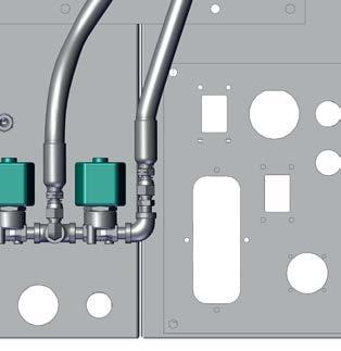
8 Boiler Water Level Sensor Low Water Cutoff Diagram 2 Pressure Relief Valve Steam Valve Actuators Bottom Front Steam Valve Actuator Top Rear Steam Valve Actuator Top Front Steam Valve Actuator Bottom Rear Steam Valve Actuator Flue Steam Purge Valve Actuator Water Purge Valve Actuator Flue Temp. Sensor Boiler Door Temp. Sensor Rear Furnace Door Blow Down Valve Actuator Rear Furnace Sight Glass Feed Water Valve Actuator Feed Water Pump 2 Circulation Pump
 Boiler Water Level Sensor Steam PSI 1 Manual Steam Pressure")

9 Diagram 3 Pressure Relief Valve Low Water Cutoff Operating Pressure Limit Switch (OPLS) Boiler Water Level Sensor Steam PSI 1 Manual Steam Pressure Gauge High Pressure Limit Switch (HPLS) Steam PSI 2 Boiler Sight Glass Front Turn bo Boiler Water Temp. Sensor Y-Strainer Feed Water Temp. Sensor 3
 Propane Solenoid Valve (2014 only) Fan Motor Ignition Transformer")

10 Diagram 4 Flame Detector Airflow Switch Burner Nozzle Control Switch High Fire Fuel cylinder/piston Propane Regulator (2014 only) Propane Solenoid Valve (2014 only) Fan Motor Ignition Transformer Direct Spark Burner Gun Assembly Burner Nozzle 20 GPH Dual Ignition Electrodes 4 Fuel Safety Solenoid Valve Low Fire Solenoid Valve 2014 Propane Burner Gun Assembly Single Ignition Electrode Propane line

11 Diagram 5 Fuel cylinder push tab Louver Actuator Low Fire adjustment bolt/nut Fuel Return line Propane line Fuel Nozzle pressure gauge Front Boiler Sight Glass Direct Spark Burner Gun Assembly 2014 Propane Burner Gun Assembly Flame Detector Burner Nozzle 20 GPH Single Ignition Electrode Dual Ignition Electrodes Propane line Fuel Nozzle pressure sensor High Fire Fuel cylinder/piston Low Fire Solenoid Louver (Upper) High Fire Solenoid Fuel Feed line Louver Close counter-weight Fan cleaning compressed air attachment and valve Louver (Lower) Fuel Pump Pressure Gauge Fuel Pump Low Fire oil regulating valve Fuel Pump Pressure Sensor 5

12 Diagram 6a (2010) Panel 1 door Panel 1 Burner Controller TS1 (Terminal Strip 1) CB (Circuit Breakers) Purge Card Burner Controller 10R Modbus Card Flame Amplifier Card Safety Relays Fan Contactor Baldor Soft Start Low Water 2 Low Water 1 6
13 Diagram 7a (2010) CB (Circuit Breakers) Panel 2 TS1 (Terminal Strip 1) Panel 3 TS1 (Terminal Strip 1) Feed Pump Contactor Circ Pump Contactor PLC (Programmable Logic Controller) AI1 (Input Card 1) AI2 (Input Card 2) AO (Output Card) Ethernet Card Ethernet Switch FB (Fuse Block) Control Relay 24v Regulator 12v Regulator FB (Fuse Block) TS2 (Terminal Strip 2) RB (Relay Block) Boiler Water Level Sensor 7
 CB (Circuit")

14 Diagram 6b ( ) Panel 1 door Panel 1 Purge Card Burner Controller TS1 (Terminal Strip 1) CB (Circuit Breakers) Burner Controller 10R Modbus Card Flame Amplifier Card Safety Relays Low Water 2 Low Water 1 Fan Contactor Baldor Soft Start 8
 Feed Pump Contactor Circ Pump Contactor PLC (Programmable Logic Controller) AI1 (Input Card")
 TS2 (Terminal Strip 2) RB (Relay Block) Boiler Water Level")
15 Diagram 7b ( ) CB (Circuit Breakers) Panel 2 TS1 (Terminal Strip 1) Panel 3 TS1 (Terminal Strip 1) Feed Pump Contactor Circ Pump Contactor PLC (Programmable Logic Controller) AI1 (Input Card 1) AI2 (Input Card 2) AO (Output Card) Ethernet Card Ethernet Switch FB (Fuse Block) Control Relay 24v Regulator 12v Regulator FB (Fuse Block) TS2 (Terminal Strip 2) RB (Relay Block) Boiler Water Level Sensor 9
 CB (Circuit Breakers) Burner Controller 10R")

16 Diagram 6c (2014-Soft Start) Panel 1 door Panel 1 TS1 (Terminal Strip 1) CB (Circuit Breakers) Burner Controller 10R Safety Relays Burner Controller Fan Contactor Purge Card Low Water 1 Low Water 2 Siemens Soft Start Modbus Card Flame Amplifier Card 10
17 Diagram 7c (2014-Soft Start) Panel 2 Panel 3 CB (Circuit Breakers) TS1 (Terminal Strip 1) TS1 (Terminal Strip 1) Feed Pump Contactor Circ Pump Contactor PLC (Programmable Logic Controller) AI1 (Input Card 1) AI2 (Input Card 2) AO (Output Card) Ethernet Card Ethernet Switch FB (Fuse Block) 24v Regulator Control Relay 12v Regulator FB (Fuse Block) TS2 (Terminal Strip 2) RB (Relay Block) Boiler Water Level Sensor 11
 CB (Circuit")

18 Diagram 6d (2014-VFD) Panel 1 door Panel 1 Burner Controller Purge Card TS1 (Terminal Strip 1) CB (Circuit Breakers) Burner Controller 10R Modbus Card Flame Amplifier Card VFD Safety Relays VFD 24v Power Low Water 1 & 2 9R 11R 12
 Feed Pump Contactor Circ Pump Contactor PLC (Programmable Logic Controller) AI1 (Input Card 1) AI2")
 TS2 (Terminal Strip 2) RB (Relay Block) Boiler Water Level Sensor")
19 Diagram 7d (2014-VFD) Panel 2 Panel 3 CB (Circuit Breakers) TS1 (Terminal Strip 1) TS1 (Terminal Strip 1) Feed Pump Contactor Circ Pump Contactor PLC (Programmable Logic Controller) AI1 (Input Card 1) AI2 (Input Card 2) AO (Output Card) Ethernet Card Ethernet Switch FB (Fuse Block) 24v Regulator Control Relay 12v Regulator FB (Fuse Block) TS2 (Terminal Strip 2) RB (Relay Block) Boiler Water Level Sensor 13


20 Diagram 8 Burner Fuel Pump Fuel Level Sensor Burner Fuel Filter Low Fire oil regulating valve Ambient Temp. Sensor Supply Water Level Sensor 14
 Supply Water Fill Valve *All valves are shown in normal operating positions 15")
21 Diagram 9 Circulation Isolation Valve Hot Water Mied Water Cold Water Circulation Isolation Valve Boiler Drain Valve Feed Water Actuator Feed Water Drain Valve Supply Water Isolation Valve Circulation Pump Feed Water Pump Supply Water Filter (T-Strainer) Supply Water Fill Valve *All valves are shown in normal operating positions 15

22 Diagram 10 Air Filter Glow Plugs Water Temperature Switch Radiator Generator End Oil Cap Oil Filter Oil Dipstick Fuel Solenoid Oil Pressure Switch Fuel / Water Separator 16


 0-12")
23 Sensors Sensor Function/Range Supply Water Level gallons Below 200 gallons *Same fill color = interchangeable Normal Trip/Alarm Options Pin Out Range Disable in Settings > Alarm Status Screen 24v mA 3 Fuel Supply Level gallons Below 30 gallons Ambient Temperature F Above 110 F Low Water 1 Low Water 2 Manual Steam Pressure Gauge Annunciate upon contact with water Annunciate upon contact with water On/Off On/Off 0-30 PSI 0-12 PSI Below 1 inch in sight glass Below 1 inch in sight glass Disable in Settings > Alarm Status Screen Disable in Settings > Alarm Status Screen Adjust in Settings > Alarm Settings 24v v 4-20mA 4-20mA High Pressure Limit Switch Set at 15 PSI Trips at 15 PSI Manual reset required 120v 120v 120v 120v Operating Pressure Limit Switch Set at 14.5 PSI Trips at 14.5 PSI Automatically resets once pressure drops New/Updated Boiler Water Level (See Test 118) 0-12 inches 4-8 inches Below 4 inches Above 10 inches Level adjustable in Settings > Water System 24v 4-20mA 17


24 Sensors Sensor Function/Range Steam PSI to 30 PSI 6-13 PSI Steam PSI to 30 PSI 6-13 PSI Feed Water Temperature F F Boiler Water Temperature F F *Same fill color = interchangeable Normal Trip/Alarm Options Pin Out Range More than 2 PSI differential More than 2 PSI differential Above 150 F differential Above 150 F differential Boiler Door Temperature F F Above 250 F Selectable and differential limit adjustable in Settings > Boiler Pressure Screen Selectable and differential limit adjustable in Settings > Boiler Pressure Screen Disable in Settings > Alarm Status Screen Adjust in Settings > Alarm Settings Disable in Settings > Alarm Status Screen Adjust in Settings > Alarm Settings Disable in Settings > Alarm Status Screen Adjust in Settings > Alarm Settings 24v v 4-20mA v 4-20mA mA v mA v 4-20mA 3 Propane Pilot PSI PSI PSI Below 5 PSI Disable in Settings > Pilot Propane 24v mA Fuel Pump PSI Gauge Fuel Nozzle PSI Gauge PSI PSI PSI PSI 18


25 Sensors Sensor Function/Range *Same fill color = interchangeable Normal Trip/Alarm Options Pin Out Range 24v 1 2 Fuel Pump PSI PSI PSI mA Nozzle 1 PSI PSI PSI High Fire: 20 PSI less than pump Low Fire: 30 PSI less than pump Disable in Settings > Alarm Status Screen 24v mA Nozzle 2 PSI PSI PSI High Fire: 20 PSI less than pump Low Fire: 30 PSI less than pump Disable in Settings > Alarm Status Screen 24v mA Black Wire = 24v White Wire = 4-20mA Flue Temperature F F Above 600 F Disable in Settings > Alarm Status Screen Adjust in Settings > Alarm Settings Airflow Switch Detects airflow = ON Does not detect airflow = OFF Adjust the sensor to be more sensitive by turning the adjustment screw counter clockwise; Turn clockwise for the sensor to be less sensitive Adjustment screw 120v 120v Flame Detector 0-15v (Screen Reading) 3-15v 19


26 Actuators Top Front Steam Valve Actuator Top Rear Steam Valve Actuator Bottom Front Steam Valve Actuator Bottom Rear Steam Valve Actuator Feed Water Valve Actuator Blow Down Valve Actuator GND mA 3. GND 4. 12v Actuators are interchangeable Connections are interchangeable Steam Purge Valve Actuator C A B A. 24v B. 4-20mA C. GND Actuators are not interchangeable Connections are interchangeable Water Purge Valve Actuator C A B A. 24v B. 4-20mA C. GND 20


27 Panel 2 Panel 3 Generator Controller Battery Front Back Fuses Panel 2 AMP Component F1 5 Top Front Steam Valve F2 5 Top Rear Steam Valve F3 5 Bottom Front Steam Valve F4 5 Bottom Rear Steam Valve F5 5 Steam/Water Purge F6 5 Feed Water Valve F7 5 BlowDown Valve Panel 3 AMP Component F v Actuators, Work Lights F v Power Regulator F3 2 12v Generator Start/Stop F v Power Regulator F5 5 24v to F6 F v to PLC F7 2 24v to Analog Sensors F8 2 24v to PLC in-output Cards F9 2 24v to Ethernet Switch F v to Touch Screen F v to Red Rocker Switch Engine AMP Component F1 40 Glow Plugs F2 40 Crank F3 40 Fuel Panel 2 WorkLights Battery AMP Component F1 30 Power to Panel 2 F2 30 Work Lights 21


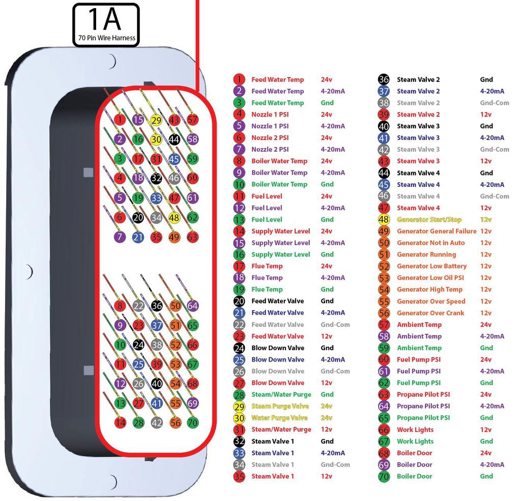
28 DT06-2S Work Lights Connections 2 1 GND 12v DT06-3S Flue Temp Water/Steam Purge A 24v GND C B GND 4-20mA 12v 24v DT06-4S Valve Actuators Tail Light Assembly GND 12v mA GND Work Turn GND Tail M12 Temp Sensors Fuel/Water Level Sensors PSI Sensors v 4-20mA 24v 4-20mA 24v mA DIN 4 Pin 2 Steam PSI Sensors 4-20mA v 22
29 Connections Note: 2014 machines only 23


30 24 Connections


31 Touch Screen Wiring v 12v 24v GND 24v to power the Touch Screen Connection 2A AMP Fuse GND 12v GND 12v 24v 24v 12v 12v 24v 12v v GND 24v 12v GND 12v Panel 3 24v 12v GND Panel 2 12v 25
32 Burner Wiring
33 Burner Wiring 2014 (Soft Start) 27
34 Burner Wiring 2014 (VFD) 28
35 Fault 1: No Purge Card The Honeywell Burner Controller is not detecting a Purge Card (Panel 1) No Purge Card Installed Check for Purge Card Install Purge Card Bad Purge Card Replace with new Purge Card Bad Burner Controller Replace Burner Controller Fault 14: High Fire Switch / Purge Hold T19 High Fire Switch Indicates that the Louver is not opening during the purge cycle or that the signal from the High Fire Switch is not reaching the Honeywell Burner Controller (See Fault 419) Mis-adjusted Louver Actuator See Test 115 to adjust/configure the Louver Actuator Faulty Louver Actuator Obstructed path of the Louver Actuator/Louvers Faulty Wiring See if the louver actuator opens the burner louvers during the 30 second purge. The louver actuator should hold the louvers open for the full 30 second purge Manually move the louvers to feel if there is any resistance or obstructions Inspect wiring for continuity, voltage, and ground Replace Louver Actuator (check other causes before buying a new component) Temporary fi: Assist the louver actuator by opening the louvers manually during the 30 second purge cycle Remove obstructions Lubricate the bushings Replace/Repair faulty wiring Faulty burner controller Check for 120v on T19 Replace burner controller 29
36 Fault 15: Flame Detected (Standby) Indicates that a flame has been detected when there should not be a flame Flame in Boiler Check for burning/smoldering debris inside the boiler Put out the flame Remove flame source Wait for flame to burn out Faulty Flame Detector or Amplifier Card Perform Test 101 Replace Flame Detector or Amplifier Card Inspect the wiring for continuity, ground, and Faulty Wiring Replace/Repair wiring proper voltage 30
37 Fault 17: Main Flame Fail Indicates that the flame detector cannot detect flame during run mode (low fire/high fire) Faulty Flame Detector Perform Test 101 Moisture/Dust on the Flame Detector lens Faulty/Loose Amplifier Card Loose Flame Detector Overtightened flame detector Misaligned Flame Detector Missing O-ring Restricted fuel flow through the main and safety fuel solenoid valves No fuel flow through the main and safety fuel solenoid valves Pilot flame lost just before main ignition Check the lens for moisture/dust Check the Amplifier Card is seated properly Check to see if the flame detector is has slop/ play. The flame detector needs to be looking straight down the sight tube Check for smashed O-ring from over-tightening the flame detector ( O-ring is between the flame detector and the sight tube) Remove the flame detector and check for the O-ring that prevents play/slop from the flame detector and aligns the flame detector with the sight tube; it also prevents malfunctions from metal on metal contact Inspect fuel paths, check for overtightened fittings Perform Test 102 This will also cause a Fault 28. Check your propane valve and pressure Replace Flame Detector (check other causes before buying a new component) Remove and dry/clean flame detector lens (weatherproof if needed) Replace/Re-seat Amplifier Card (Re-seat and secure in place with tape or a tie wrap) See Diagram 6 Hand tighten flame detector Loosen the flame detector Replace flame detector O-ring Remove restrictions Replace faulty fuel solenoid valve Turn propane valve on Refill/Replace propane tank 31
38 Fault 18: Flame Detected (Pre-Purge) Indicates that a flame has been detected when there should not be a flame Flame in Boiler Check for burning/smoldering debris inside the boiler Put out the flame Remove flame source Wait for flame to burn out Faulty Flame Detector or Amplifier Card Perform Test 101 Replace Flame Detector or Amplifier Card Inspect the wiring for continuity, ground, and Faulty Wiring Replace/Repair wiring proper voltage 32
39 Fault 19: Main Flame Ign Indicates flame was lost during the first 10 seconds of the RUN state Flame Detector Fuel Faulty Flame Detector Perform Test 101 Moisture/Dust on the Flame Detector lens Faulty/Loose Amplifier Card Loose Flame Detector Overtightened flame detector Misaligned Flame Detector Missing O-ring Low Fire Nozzle Pressure is Low/high Fuel Pump Pressure is Low No fuel flow through the main and safety fuel solenoid valves Restricted fuel flow through the main and safety fuel solenoid valves Nozzle fuel feed/return lines are crossed No Fuel Pump Pressure Faulty Wiring Check the lens for moisture/dust Check the Amplifier Card is seated properly Check to see if the flame detector is has slop/play. The flame detector needs to be looking straight down the sight tube Check for smashed O-ring from over-tightening the flame detector ( O-ring is between the flame detector and the sight tube) Remove the flame detector and check for the O-ring that prevents play/slop from the flame detector and aligns the flame detector with the sight tube; it also prevents malfunctions from metal on metal contact Perform Test 102 Replace Flame Detector (check other causes before buying a new component) Remove and dry/clean flame detector lens (weatherproof if needed) Replace/Re-seat Amplifier Card (Re-seat and secure in place with tape or a tie wrap) Hand tighten flame detector Loosen the flame detector Replace flame detector O-ring Set nozzle pressure to PSI (See Test 101) Set the pump pressure to PSI (See Test 101) Inspect fuel paths, check for overtightened fittings Check nozzle fuel feed/return lines are connected properly Check for fuel at the pump Check that the fan/pump shaft coupler is in place Inspect the wiring for continuity, ground, and proper voltage Replace faulty fuel solenoid valve Remove restrictions Connect nozzle fuel feed/return lines properly (See Diagram 5) Bleed the fuel pump Replace the fuel pump Repair/Replace the fan/pump shaft coupler Replace/Repair wiring 33
40 Fault 20: Low Fire SW Off / Purge Hold T18 Low Fire Switch Indicates that the Louver is not closing during the purge cycle or that the signal from the Low Fire Switch is not reaching the Honeywell Burner Controller Mis-adjusted Louver Actuator See Test 115 to adjust/configure the Louver Actuator Faulty Louver Actuator Faulty Wiring See if the louver actuator returns to the closed position after the 30 second purge Inspect wiring for continuity, voltage, and ground Replace Louver Actuator (check other causes before buying a new component) Replace/Repair faulty wiring 34
41 Fault 28: Pilot Flame Fail (Page 1 of 2) Indicates a failure in either the ignition system or the safety system that detects the pilot flame IMPORTANT: Perform Test 101 first to determine whether or not a pilot flame is present Flame Detector No Spark Faulty Flame Detector Perform Test 101 Moisture/Dust on the Flame Detector lens Faulty/Loose Amplifier Card Loose Flame Detector Overtightened flame detector Misaligned Flame Detector Missing O-ring Check the lens for moisture/dust Check the Amplifier Card is seated properly Check to see if the flame detector is has slop/play. The flame detector needs to be looking straight down the sight tube Check for smashed O-ring from over-tightening the flame detector ( O-ring is between the flame detector and the sight tube) Remove the flame detector and check for the O-ring that prevents play/slop from the flame detector and aligns the flame detector with the sight tube; it also prevents malfunctions from metal on metal contact Replace Flame Detector (check other causes before buying a new component) Remove and dry/clean flame detector lens (weatherproof if needed) Replace/Re-seat Amplifier Card (Re-seat and secure in place with tape or a tie wrap) Hand tighten flame detector Loosen the flame detector Replace flame detector O-ring Dirty electrode assembly Check for spark Clean electrode assembly Improper electrode gap/orientation Check for spark Set electrode gap and orientation (Test 105) Spark grounding to burner Ignition cable disconnected Check ignition cable(s) *2014 s one cable Connect ignition cable(s) *2014 s one cable Faulty ignition transformer Perform Test 104 Replace ignition transformer Propane tank valve closed Check propane tank Open propane tank valve *Propane: 2014 s Propane tank empty Check propane tank Refill propane tank Clogged burner regulator Test that propane is passing through the burner regulator Replace burner regulator To prevent future clogs, clean propane hoses using compressed air Fault 28 continued on net page 35
42 Fault 28: Pilot Flame Fail (Page 2 of 2) Indicates a failure in either the ignition system or the safety system that detects the pilot flame IMPORTANT: Perform Test 101 first to determine whether or not a pilot flame is present *Propane: 2014 s Fuel Adjust regulator PSI output (Clockwise increases PSI) Improper burner regulator adjustment Perform Test 106 Faulty propane solenoid Perform Test 103 Replace / Clean propane solenoid Disconnect propane regulator; during pilot ignition, spray compressed air through the propane Clogged propane hose/nozzle solenoid valve to clear the hose and nozzle of debris. Faulty propane tank regulator; too much propane PSI Faulty propane tank regulator damaged the burner regulator Low Fire Nozzle Pressure is Low/high Fuel Pump Pressure is Low No fuel flow through the main and safety fuel solenoid valves Restricted fuel flow through the main and safety fuel solenoid valves Nozzle fuel feed/return lines are crossed No Fuel Pump Pressure Faulty Wiring Test for 10 PSI after the propane tank regulator (the burner regulator inlet supports 10 PSI ma) Perform Test 102 First replace the propane tank regulator Then replace the burner regulator Set nozzle pressure to PSI (See Test 116) Set the pump pressure to PSI (See Test 116) Inspect fuel paths, check for overtightened fittings Check nozzle fuel feed/return lines are connected properly Check for fuel at the pump Check that the fan/pump shaft coupler is in place Inspect the wiring for continuity, ground, and proper voltage Replace faulty fuel solenoid valve Remove restrictions Connect nozzle fuel feed/return lines properly (See Diagram 5) Bleed the fuel pump Replace the fuel pump Repair/Replace the fan/pump shaft coupler Replace/Repair wiring 36

 Repair/Replace fan motor Failed fan motor Check for 3 phase power reaching fan motor if it is a 2014 DewPoint with a VFD Check for single phase 240v voltage reaching the fan motor")
43 Fault 29: Lockout ILK (Airflow Switch / VFD) Indicates that the VFD/fan motor did not turn on or the airflow switch did not detect the fan air moving Clogged Airflow Switch / Aluminum tubes Check the airflow switch and hoses for obstructions Clean out aluminum tubes Remove obstructions Remove and clean sensor air inlet port Adjust airflow switch to most sensitive setting Airflow Switch out of adjustment Fan is spinning but airflow switch is not tripped Counter-clockwise = More sensitive Clockwise = Less sensitive Over-greased fan motor Has the fan motor been over greased?(1 pump per year) Repair/Replace fan motor Failed fan motor Check for 3 phase power reaching fan motor if it is a 2014 DewPoint with a VFD Check for single phase 240v voltage reaching the fan motor Repair/Replace fan motor Faulty 11r Relay (Panel 1 Door) Applicable to 2014 machines with a VFD Check/Replace 11r Relay (Panel 1 Door) Faulty/non-programmed VFD (some 2014 s) Faulty/Maladjusted Siemens Soft Start (2014) Faulty/Maladjusted Baldor Soft Start ( ) Faulty wiring Watch VFD LCD screen as the fan motor starts; It should ramp from 0-60 over 15 seconds Check that the load is set between: %25 - %50 Check that the time is set between: 5s - 10s Check that the load is set between: %25 - %50 Check that the time is set between: 5s - 10s Inspect the wiring for continuity, ground, and proper voltage Program the VFD (See Test 114) Replace VFD Adjust the load to between: %25 - %50 Adjust the time to between: 5s - 10s Replace the soft start Adjust the load to between: %25 - %50 Adjust the time to between: 5s - 10s Replace the soft start Replace/Repair wiring 37
44 Fault 45: Low Fire Switch Off Indicates Low Fire Switch was not on during main oil ignition (Low Fire Switch turning on is required during main oil ignition) Mis-adjusted Louver Actuator See Test 115 to adjust/configure the Louver Actuator Faulty Louver Actuator Obstructed path of the Louver Actuator/Louvers Faulty Wiring See if the louver actuator opens the burner louvers during the 30 second purge. The louver actuator should hold the louvers open for the full 30 second purge Manually move the louvers to feel if there is any resistance or obstructions Inspect wiring for continuity, voltage, and ground Replace Louver Actuator (check other causes before buying a new component) Temporary fi: Assist the louver actuator by opening the louvers manually during the 30 second purge cycle Remove obstructions Lubricate the bearings Replace/Repair faulty wiring Fault : Call Service Check wiring behind the Burner Controller Replace the Burner Controller 38
 Have you performed a wet layup recently (Wet Layup fills the boiler completely full of water) Manually reset switch 1 or more pigtail valves are open High Pressure")
 Adjust the calibration nut to 15 PSI Replace High Pressure Limit Switch Adjust the calibration nut to 14.")
45 Fault 200: High Pressure Limit Switch (HPLS) is tripped The High Pressure Limit Switch shuts off the burner anytime it is tripped; it trips anytime boiler pressure is over 15 PSI Wet Layup (causes more than 15 PSI in the boiler) Have you performed a wet layup recently (Wet Layup fills the boiler completely full of water) Manually reset switch 1 or more pigtail valves are open High Pressure Limit Switch faulty / out of calibration Operating Pressure Control Switch faulty / out of calibration Steam can be seen coming out of the front supply water tanks Perform Test 108 Perform Test 109 Close the open pigtail valves (don t forget the one behind the manual PSI gauge) Adjust the calibration nut to 15 PSI Replace High Pressure Limit Switch Adjust the calibration nut to 14.5 Replace Operating Pressure Control Switch Faulty SR-4 Relay (Panel 1) Fault 243 Swap SR-4 with spare 120v relay (Panel 1) Inspect the wiring for continuity, ground, and Faulty Wiring Replace/Repair wiring proper voltage 39
46 Fault 201: Turn Burner Switch ON Indicates that the burner is not getting 120v power Burner Door Switch is OFF Turn the switch to ON Circuit Breaker B6 is tripped (Panel 1) Reset the circuit breaker Main Generator Circuit Breaker is tripped Reset the circuit breaker Generator Plug disconnected Connect generator plug to burner Faulty Generator End Faulty Wiring Check generator output voltage See Test 121 Inspect the wiring for continuity, ground, and proper voltage Replace Voltage Regulator Replace Generator Replace/Repair wiring 40
47 Fault 202: Operating Pressure Control Switch (OPLS) is tripped The Operating Pressure Control Switch shuts off the burner anytime it is tripped; it trips anytime boiler pressure is over 14.5 PSI. Switch auto-resets at 12.5 PSI 1 or more pigtail valves are open Faulty Steam Pressure Sensor (Fault 207) Operating Pressure Control Switch faulty / out of calibration Steam can be seen coming out of the front supply water tanks Menu > Settings > Boiler Pressure > Pressure Sensor Selection If Steam PSI 1 & 2 are reading more than 2 PSI different, then compare their readings to the manual pressure gauge on the top front of the boiler and select the sensor that matches the pressure reading to temporarily run on one Steam PSI sensor. Perform Test 109 Fault 203: Boiler Water Level is high See Fault 403: Boiler water level higher than set point / Boiler overflowing Close the open pigtail valves (don t forget the one behind the manual PSI gauge) Replace Steam Pressure Sensor Adjust the calibration nut to 14.5 Replace Operating Pressure Control Switch Faulty SR-5 Relay (Panel 1) Fault 244 Swap SR-5 with spare 120v relay (Panel 1) Inspect the wiring for continuity, ground, and Faulty Wiring Replace/Repair wiring proper voltage Fault 204: Pilot Propane Level is low Indicates that the propane level count is down to 5 remaining lights (this can often be inaccurate) Propane level is low Check propane level Refill propane tank Refill propane tank & reset propane light count (Menu > Settings > Pilot Propane > Reset Pilot Propane lighting count is not accurate Propane Gauge) 41


48 Fault 206: Supply Water Is Empty Indicates that the supply water is empty Supply water is empty Fill the supply water tanks with treated water Sensor is disconnected Check to see if sensor is disconnected Connect sensor Faulty Sensor Replace sensor Damaged wire harness Inspect 70 pin wire harness for water damage Repair/Replace damaged components Inspect the wiring for continuity, ground, and Faulty Wiring Replace/Repair wiring proper voltage Fault 207: Pressure Differential Alarm Indicates that the two steam pressure sensors are reading more than 2 PSI (default setting) apart from each other 42 Faulty/disconnected steam pressure sensor 1 or more pigtail valves are open Compare steam pressure sensors against manual pressure gauge to determine which sensor is reading incorrectly Steam can be seen coming out of the front supply water tanks Replace sensor (RELEASE BOILER PRESSURE BEFORE REPLACING) Reconnect sensor Temporary fi: Menu > Settings > Boiler Pressure > Pressure Sensor Selection > Select the sensor that matches the manual pressure gauge (NOT A PERMANENT FIX) Close the open pigtail valves (don t forget the one behind the manual PSI gauge) Faulty Input Card 1 in the PLC Perform Test 113 Replace faulty input card (see Test 113 ) If after replacing the sensor and the input card Faulty PLC 1 there is still an abnormal reading this indicates a faulty PLC Replace PLC *Bad steam pressure sensors can damage input cards and PLC s, they can also cause ma readings for all inputs on card 1 on the PLC ** If the PLC or input card are replaced before a possible faulty steam pressure sensor is replaced, the steam pressure sensor can damage the newly replaced components. (Replace components in order shown above)
49 Fault 208: Flue Temp is High Indicates flue temperature is above 600 F Soot has built up on tubes causing high flue temperatures Faulty Flue Temp Sensor Faulty Wiring If you don t trust the Flue temperature reading on the touch screen, confirm temperature with infrared gun Confirm with an infrared gun that the actual temperature is not what is shown as the flue temp reading on the touch screen Sudden spikes in flue temp readings also indicate a faulty flue temp sensor Inspect the wiring for continuity, ground, and proper voltage Clean the tubes :) Replace Flue Temp Sensor Replace/Repair wiring Faulty Input Card 1 in the PLC Perform Test 113 Replace faulty input card (See Test 113 ) If after replacing the sensor and the input card Faulty PLC 1 there is still an abnormal reading this indicates a faulty PLC Replace PLC *Bad Flue temperature sensors can damage input cards and PLC s, they can also cause ma readings for all inputs on card 1 on the PLC ** If the PLC or input card are replaced before a possible faulty flue temp sensor is replaced, the faulty flue temp sensor can damage the newly replaced components. (Replace components in order shown above) *** Alarm can be disabled in Menu > Settings > Alarm Status > Flue Temp Alarm 43

50 Fault 209: Feed Water and Boiler Water Temp. Differential limit has been Eceeded Indicates that the difference in temperature between the feed water temperature sensor and the boiler water temperature sensor is more than 150 F Clogged/dirty Y-Strainer Flush Y-Strainer by opening for 3 seconds under steam pressure Clean/replace Y-Strainer Filter Circulation Pump not running Circulation Pump isolation valves are closed Faulty temperature sensor Pump contactor overload is tripped Check valve positions (both circulation pump inlet and outlet valves) Compare reading with actual temperature (Faulty sensors normally read very high or very low) Inspect circulation pump contactor; if yellow stripe is present in test window, reset is required Circuit breaker is tripped Check circuit breaker (Panel 2) Yellow weatherproof 240v plug loose/ disconnected Loose wires inside pump motor housing Faulty/Seized pump Water system not enabled on touch screen Faulty relay between PLC and motor contactor PLC output not sending signal Faulty wiring Inspect yellow weatherproof plug to see if it is loose or has a bad connection Inspect wire nuts and ensure that 240v is reaching the pump Manually attempt to spin motor (motor should spin freely) Circulation pump should be running anytime water system is enabled and low water 1 & 2 are satisfied Check Relay to see if light is on (Panel 2 Relay Block 2nd relay) Check for 24v on PLC output Y5 (Menu > Diagnostics > Inputs/Outputs > Discrete Outputs > Y5) Inspect the wiring for continuity, ground, and proper voltage Open valves (both circulation pump inlet and outlet valves) Replace sensor Reset pump contactor overload (Panel 2) Reset Circulation pump circuit breaker (Panel 1) Reconnect yellow weatherproof plug behind the burner that gives 240v to the pump Secure wire nuts inside pump motor housing Replace pump Enable water system (Menu > Operations > System Start) Replace Relay Replace PLC Replace/Repair wiring 44
51 Fault 210: Ambient Temperature is High Indicates that the ambient temperature is above the alarm setpoint (default 100F) Ambient temperature is high Heat from tractor is causing the sensor to read higher than normal Faulty sensor Faulty wiring Fault 212: Low Water 2 tripped See Fault 400: Low Water 1 or 2 Tripped Compare reading to actual ambient temperature Compare reading to actual ambient temperature Compare reading to actual ambient temperature Inspect the wiring for continuity, ground, and proper voltage Reconsider using the DewPoint at these temperatures Stop baling if internal bale temperatures reach more than 135 F Adjust the tractor heat offset by touching the ambient temperature icon on the touch screen (default is 10 F) Replace sensor Replace/Repair wiring Fault 211: Furnace Door Temp is High Indicates that the rear furnace door is above 250 F ( s are the only 6110 s to have this sensor) Temperature is above 250 F Faulty sensor Use infrared thermometer to check rear furnace door Check the rear furnace door for paint bubbling and discoloration from ecessive heat Use infrared thermometer to check rear furnace door area for normal temperatures (below 250 F) Replace rear furnace door insulation and rope gaskets Replace sensor Fault 213: Boiler taking longer than epected to fill See Fault 400: Low Water 1 or 2 Tripped 45
52 Fault 214: Data Logging Failed: Replace USB Drive Indicates that the screen can no longer detect the USB flash drive that should be installed at the bottom of the touch screen. This fault will not prevent operation of the machine, but sensor trending will not record. Press Confirm to continue operation No USB drive in touch screen Faulty USB drive Look in bottom of screen to see if USB drive is Plug in new USB drive (recommended 8gb) plugged in Replace with new USB drive (recommended 8gb) Fault 215: Manual Valve Operation is ON Indicates that manual valve operation is on Menu > Operations > Manual Mode Fault 224: Trouble Communicating with one or more Sensors Indicates that one or more 4-20mA sensors are not communicating with the PLC (At least 4mA is needed on each sensor for communication to be established. 4mA=min 20mA=ma) Sensor is unplugged Check sensor connections Plug in sensor Sensor is damaged Wire harness damage Test with interchangeable sensor (many sensors are interchangeable)(see Sensor page) Inspect wiring at sensor end and at panel end Verify with a known functioning sensor Check for 24v on wire harness end Replace damaged sensor Replace/Repair wire harness Blown Fuse Check fuses in panel 3 Replace blown fuse PLC input damage Check analog inputs for normal function Replace PLC Input card(s) and/or Replace PLC Inspect wiring for continuity, voltage, and Faulty Wiring Replace/Repair faulty wiring ground 46
53 Fault 225: Burner Modbus signal failure The Mod Bus connection is the way that the Honeywell Burner Controller communicates with the PLC. If the connection is lost, the burner will not function properly Modbus cable faulty/unplugged Modbus address not set to 78 Faulty Modbus Module PLC Modbus connection shorting Fault 228: Steam Pressure is low See Fault 409: Loss of steam pressure during operation Inspect Modbus cable on PLC port 2 (Panel 2) Plug in / Replace Modbus cable and top of burner controller (Panel 1) Reset module by turning both pots to 99, Visually inspect ModBus module then turn the pots to 78 Replace Modbus module Disassemble DB-15 (PLC port 2) connector and Repair/Replace Modbus wire harness check for shorted and/or grounded pins Fault 229: Boiler water temp. is low and steam pressure is normal See Fault 411: Circulation Pump not running Fault 230: Turn Water System On Indicates that field mode is active and the water system is off Causes Field mode is active and the water system is off Turn water system on Fies Fault 231: Boiler water level is too high for operation See Fault 403: Boiler water level higher than set point / Boiler overflowing 47
54 Fault 232: Generator status (Page 1 of 2) Indicates Generator has failed and shut off for safety Causes Indicates Fies Overspeed (Flashing light) = Underspeed Main fuel shutoff valve closed Water separator fuel valve closed Loose fuel hose clamp / air in fuel line Clogged in-line fuel filter Open main fuel shutoff valve located beneath the front left fuel tank Open water separator fuel valve Check all 10 fuel hose clamps for tightness on the generator fuel path Remove filter and see if you can blow air through it (replace every 250 hours) Tighten loose fuel hose clamps Replace in-line fuel filter Clogged engine fuel filter Replace every 250 hours Replace engine fuel filter Remove hose from output side of the lift pump and see Faulty lift pump if fuel comes out during engine pre ignition (use generator controller to turn engine off before it starts to crank) Replace fuel lift pump Overspeed (steady light) The Generator is running faster than normal Contact Dealer Low Battery Voltage Over Frequency Under Frequency AC Over Voltage Battery Voltage is below normal The Generator is running faster than normal The Generator is running slower than normal There is more voltage than normal Charge/Replace battery Use the Battery Cutoff Switch when the steamer is not in use to preserve battery Check and adjust engine throttle and lock nut The frequency should be set to 60hz Check and adjust engine throttle and lock nut The frequency should be set to 60hz Check and adjust the generator automatic voltage regulator (See Test 121) Voltage between L1 and L2 should be 240v AC Under Voltage Low Oil Pressure 48 There is less voltage than normal There is low oil pressure in the engine Oil Pressure should be between PSI Check and adjust the generator automatic voltage regulator (See Test 121) Voltage between L1 and L2 should be 240v Check engine for proper oil level Check/Replace the engine oil filter Replace Oil Pressure Switch
55 Fault 232: Generator status (Page 2 of 2) Indicates Generator has failed and shut off for safety Overcrank Causes Indicates Fies Check engine coolant level High Engine Temperature Engine Temperature is above normal Check belt, fan, and radiator Engine Failed to Stop The Engine failed to stop Turn off Fuel Valve Fuel not reaching injector pump Air in fuel supply line Faulty Fuel Relay or blown fuse Faulty Crank Relay or blown fuse Faulty Fuel Shutoff Solenoid Faulty Glow Plugs / Cold Weather Faulty wiring Remove supply hose from injector pump to see if fuel is reaching the engine Follow the fuel line from tank to engine until blockage is found (most common is the in-line fuel filter) Remove supply hose from injector pump to see if fuel is reaching the engine Inspect all hoses and hose clamps for air leaks Check fuse Test output with multimeter while starting the engine Check fuse Test output with multimeter while starting the engine Remove solenoid from engine and test with 12v to see if it functions Black-GND White-Pull Red -Hold *DO NOT START ENGINE WITH SOLENOID RE- MOVED. RUNAWAY ENGINE WILL OCCUR Inspect glow plugs Check Pre-heat Relay Check Pre-heat Relay fuse Inspect entire wiring path checking for continuity, ground, and proper voltage Replace in-line fuel filter Replace engine fuel filter Replace lift pump Remove any fuel blockages Open the Water Separator Shutoff Valve Open the main Fuel Shutoff Valve Replace Water Separator Tighten loose hose clamps Replace/Repair hoses Replace fuse Replace relay Replace fuse Replace relay Replace Fuel Shutoff Solenoid Replace Glow Plugs Replace Pre-heat Relay Replace Pre-heat Relay fuse Repair/Replace faulty wiring section 49
56 Fault 239: Initiate Hold: AC Frequency / Noise Indicates that the Burner Controller has restarted. The Burner has shutoff and will automatically re-fire. This Fault displays if this condition happens twice in 1 hour. If this problem persists, the Burner Controller may need to be replaced. Faulty Burner Controller Replace Burner Controller if problem persists Fault 240: Control Switch Relay SR-1 did not annunciate Indicates that Control Switch Relay SR-1 did not annunciate. Burner will not operate Faulty SR-1 Relay: Part #781-1C-120A Swap relay with another 120v relay Replace SR-1 Relay in Panel 1 Fault 241: Low Water 1 Relay SR-2 did not annunciate Indicates that Low Water 1 Relay SR-2 did not annunciate. Burner will not operate Faulty SR-2 Relay: Part #781-1C-120A Swap relay with another 120v relay Replace SR-2 Relay in Panel 1 Fault 242: Low Water 2 Relay SR-3 did not annunciate Indicates that Low Water 2 Relay SR-3 did not annunciate. Burner will not operate Faulty SR-3 Relay: Part #781-1C-120A Swap relay with another 120v relay Replace SR-3 Relay in Panel 1 50
57 Fault 243: High Pressure Limit Switch Relay SR-4 did not annunciate Indicates that High Pressure Limit Switch Relay SR-4 did not annunciate. Burner will not operate Faulty SR-4 Relay: Part #781-1C-120A Swap relay with another 120v relay Replace SR-4 Relay in Panel 1 Fault 244: Operating Pressure Control Relay SR-5 did not annunciate Indicates that the Operating Pressure Control Relay SR-5 did not annunciate. Burner will not operate Faulty SR-5 Relay: Part #781-1C-120A Swap relay with another 120v relay Replace SR-5 Relay in Panel 1 Fault 245: Burner Relay SR-6 did not annunciate Indicates that Burner Relay SR-6 did not annunciate. Burner will still operate Faulty SR-6 Relay: Part #781-1C-120A Swap relay with another 120v relay Replace SR-6 Relay in Panel 1 Fault 246: Fan VFD SR-7 did not annunciate Indicates that Fan VFD SR-7 did not annunciate. Burner will still operate Faulty SR-7 Relay: Part #781-1C-120A Swap relay with another 120v relay Replace SR-7 Relay in Panel 1 Fault 247: Airflow Switch SR-8 did not annunciate Indicates that Airflow Switch SR-8 did not annunciate. Burner will still operate Faulty SR-8 Relay: Part #781-1C-120A Swap relay with another 120v relay Replace SR-8 Relay in Panel 1 51
58 Fault 248: Touch Screen Version is incompatible with this DewPoint Indicates that the programming version on the touch screen and the PLC are incompatible An older/newer steamer touch screen has been connected to a newer/older steamer PLC lost the version # Check the version in Menu > Information > Version (the first digit in the PLC and Touch Screen Version should match) 2016 and older machines should be version Machines should be version 3. Ignore the fault Locate and use appropriate screen for appropriate steamer Update to the latest version of Touch Screen and PLC Update to the latest version of Touch Screen and PLC 52


59 Fault 249: Check Network Cable or Fault 214: Missing USB Drive (PLC-015: DEV001 No Device Found) Indicates that the network connection between the PLC and the touch screen has been lost Loose network cable Faulty network cable Check the network cable at the bottom of the touch screen and also in the PLC Check the 6 network cable between the PLC and the Ethernet switch Run an eternal network cable from the touch screen to the Ethernet switch: If this fies your problem, you have a faulty network cable Faulty PLC Ethernet switch Replace Ethernet switch: Part #10378 Faulty PLC network card Replace network card: Part #10377 Faulty PLC Replace PLC: Part #10374 Faulty touch screen Replace touch screen: Part #10370 Fault 214 See Fault 214 Plug the network cable securely into the bottom of the touch screen and PLC Plug the 6 network cable securely into both PLC and Ethernet switch Replace RJ45 Network RJ45 connectors on eisting network cable (any IT store will be able to do this) Replace/Repair the internal touch screen wire harness Replace/Repair the internal electrical panel wire harness Replace/Repair the main touch screen wire harness 53
 is plugged Remove and clean the supply water filter (T-strainer) Replace supply water filter (T-strainer) Air lock (Feed water pump) No supply water;")
60 Fault 400: Low Water 1 or 2 tripped (Page 1 of 2) (Indicates boiler water level is too low for safe operation) Supply water valve is closed Check supply water valve in rear door area Open supply water valve Supply Water Filter (T-Strainer) is plugged Remove and clean the supply water filter (T-strainer) Replace supply water filter (T-strainer) Air lock (Feed water pump) No supply water; faulty supply water level sensor Loosen the supply water filter and open the supply water valve to purge possible air lock Check to see if there is water in the supply Replace supply water level sensor tanks Feed Water Actuator not Opening (Fault 408) Faulty feed water actuator Blown fuse Test for functionality in Manual Mode: Menu > Operations > Manual Mode (Test at 30%, 60%, and 100% open) Swap connection with blowdown actuator to confirm faulty actuator A seized valve can cause blown fuses; remove actuator and check for seized valve Temporary Fi: Menu > Settings > Water System and set Feed Water Induction Valve Min Open to 100% (actuator will still need to be replaced) Replace feed water actuator Replace Fuse F1 in Panel 3 Replace Fuse F6 in Panel 2 Remove actuator and manually open and close seized valve PLC not in Run mode (Panel 2) On the bottom right of the PLC ensure that the toggle switch is set to Run Faulty PLC analog output card If no actuators are working, this could be your problem Replace PLC analog output card Low battery voltage Start the generator Charge/Replace battery Faulty wiring Inspect the wiring for continuity, ground, and proper voltage Repair/Replace wiring Faulty boiler water level sensor Perform Test 110 Clean/Replace boiler water level sensor Swap purple and red wires in blue low water Faulty/Dirty low water cut off probe housing to see if the fault changes, indicating a faulty/dirty probe Clean/Replace probe 54
61 Fault 400: Low Water 1 or 2 tripped (Page 2 of 2) (Indicates boiler water level is too low for safe operation) Feed Pump not running (Fault 410) Faulty low water cut off relay Loose low water cut off relay base screw terminals Moisture in blue low water cut off housing and/or 6B connection Faulty wiring Pump contactor overload is tripped Inspect feed pump contactor; if yellow stripe is present in test window, reset is required Swap suspected faulty low water cut off relay with the other low water cut off relay to see if the fault changes, indicating a faulty relay Replace low water cut off relay Tighten screw terminals behind the low water cut off relay Check for moisture damage in the blue low water cut off housing on top of the boiler (water can travel down the conduit line and interfere with the low water cut off signal) Inspect the wiring for continuity, ground, and proper voltage Reset feed pump contactor overload (Panel 2) Circuit breaker is tripped Check circuit breaker (Panel 2) Reset feed pump circuit breaker (Panel 1) Yellow weatherproof 240v plug loose/ disconnected Loose wires inside pump housing Faulty/Seized pump Water system not enabled on touch screen Faulty relay between PLC and motor contactor PLC output not sending signal Inspect yellow weatherproof plug to see if it is loose or has a bad connection Inspect wire nuts and ensure that 240v is reaching the pump Manually attempt to spin motor (motor should spin freely) Feed pump should be running anytime water system is enabled Check Relay to see if light is on (Panel 2 Relay Block 2nd relay) Check for 24v on PLC output Y4 (Menu > Diagnostics > Inputs/Outputs > Discrete Outputs > Y4) Reconnect yellow weatherproof plug behind the burner that gives 240v to the pump Secure wire nuts inside pump housing Replace pump Enable water system (Menu>Operations>System Start) Replace Relay Replace PLC Remove moisture from conduit and connections Tighten sensor stems and crush washer Replace damaged connectors Repair/Replace wiring 55
62 Fault 401: Boiler not filling / slowly filling with water (See Fault 400) Supply tanks empty See Fault 206 Supply Water Filter (T-Strainer) is Remove and inspect the screen for debris Clean the supply water filter plugged Supply Water Valve is closed Open supply water valve by putting the handle in line with the pipe Inspect valve to see if it is closed Feed Water Valve is not opening Inspect valve to see if it is closed (the red indicator on top will be perpendicular to the pipe if it is closed) (Valve should not be closed) Inspect the actuator to ensure it is still attached properly to the valve Inspect the coupler between the valve and the actuator Check the ball valve for free movement See Fault 408 in the troubleshooting guide Pump not functioning Check that the feed water pump is running See Fault 410 Feed Water Pump not running Boiler Water Level Sensor malfunction Intermittent readings Level on the touch screen does not match sight glass level Replace Boiler Water Level Sensor (See Test 110) 70 Pin connector pins are damaged Disconnect 70 pin connector from panel 2 Repair/Replace bad pins in 70 pin connector Fault 402: Faulty PLC Input Card (See Test 113) Bad Flue Temp Sensor Steam PSI Sensor All other analog input sensors A faulty input card will normally give you abnormal readings on one or more inputs Determine which sensor caused the card to fail by unplugging each sensor linked to the input card one at a time until other input readings return to normal After replacing the faulty sensor, a faulty input card will still give you abnormal readings on one or more inputs ALWAYS REPLACE THE FAULTY SENSOR AND INSPECT WIRING BEFORE REPLACING THE INPUT CARD Replace Input Card Turn Power off and be gentle (Input Cards are delicate) *Always turn the power off before replacing any sensor or any card 56
63 Fault 403: Boiler water level higher than set point / Boiler overflowing Wet Layup Faulty Boiler Water level Sensor Faulty feed water valve actuator (stuck open/improperly connected) Boiler water level target set too high Have you performed a wet layup recently (Wet Layup fills the boiler completely full of water) Compare touch screen reading to water level in sight glass (if they do not match, perform Test 110 to determine if the boiler water level sensor is working) Test in Manual Mode to see if feed water valve actuator moves Menu > Operations > Manual Mode Ensure that the valve is coupled to the actuator correctly and that the valve is actually opening and closing Check target in Menu > Settings > Water System > Boiler Water Level Fieldwork Drain water from boiler to desired level Clean the Boiler Water Level Probe Ensure the wire nuts are secure and connected in the top conduit housing above the water level sensor Replace Boiler Water Level Sensor: Part #11040 Replace feed water valve actuator: Part #10363 Swap feed water actuator with a steam actuator See Fault 408 Press Load Defaults in Menu > Settings > Water System > Boiler Water Level Fieldwork Lower Boiler Water Level Fieldwork in Menu > Settings > Water System > Boiler Water Level Fieldwork Inspect the wiring for continuity, ground, and Faulty wiring Replace/Repair wiring proper voltage 70 Pin connector pins are damaged Disconnect 70 pin connector from panel 2 Repair/Replace bad pins in 70 pin connector 57


64 Fault 404.a: Bottom rear work lights will not turn on Tractor controls the bottom rear work lights Trailer light harness disconnected Check light harness Plug the harness in Trailer light harness faulty Inspect the wiring for continuity, ground, and proper voltage Check each light harness pigtail Replace/Repair harness Tractor not sending 12 volt supply Check tractor fuses and supply voltage Repair tractor supply voltage Fault 404.b: Side and top rear work lights will not turn on DewPoint controls the side and top rear work lights Button is not pressed on Touch Screen Green button = ON Red button = OFF Press light icon on touch screen Faulty light harness relay Test with spare 12v relay (2014 s have a spare relay in Panel 1) Replace the in-line light harness relay Blown Fuse Check Fuse (F1) in Panel 3 Replace blown fuse (F1) Panel 3 Check for an LED indicator light on Panel 2 Faulty panel relay Replace Panel 2 relay (RB#8) relay block #8 Blown in-line battery fuse 58 Check in-line 30A fuse from battery Check for break in the wire harness where the in-line fuse is spliced in Replace in-line 30A battery fuse Repair in-line wire splice (See Fuses Page)
65 Fault 405: Touch Screen controller will not turn on Low battery voltage Start the generator Charge/replace battery Blown fuse F4, F5, F10, F12 (Panel 3) Fuse should light up with a red LED if blown Replace fuse F4, F5, F10, or F12 (Panel 3) Blown in-line battery fuse Check in-line 30A fuse from battery Check for break in the wire harness where the in-line fuse is spliced in Replace in-line 30A battery fuse Repair in-line fuse wire splice (See Fuses Page) Faulty control relay (Panel 3) Replace 12v control relay in Panel 3 (2014 s have a spare in Panel 3) No green light can indicate a failure, especially Faulty 24v regulator (Panel 3) if the red rocker switch on the touch screen is Replace 24v regulator lit up, indicating the 12v system is functioning Faulty wiring Inspect the wiring for continuity, ground, and proper voltage Replace/Repair wiring Fault 406: Steam is coming out of front water tanks One or more pigtail valves open (top front of boiler) Check pigtail valves Close all pigtail valves (don t forget the valve behind the manual pressure gauge) Faulty boiler sight glass check valve Inspect check valve for leaks Replace boiler sight glass check valve 59
66 Fault 407: Burner Smoking Indicates burner air : fuel ratio is not working properly (Black smoke = not enough air / too much fuel) (White smoke = too much air / not enough fuel) 60 Dirty burner fan Check the burner fan for dirt build up Clean the burner fan Nozzle fuel feed/return lines are crossed Check nozzle fuel feed/return lines are connected properly Connect nozzle fuel feed/return lines properly (See Diagram 5) Low fire/high fire tuned incorrectly Tune the burner (See Test 116) Incorrect fuel pump pressure Set fuel pressure to PSI (See Test 116) Set low fire fuel nozzle pressure to PSI (See Test 116) Incorrect fuel nozzle pressure *When the pump and low fire nozzle pressures are set correctly, the high fire fuel nozzle pressure should be around PSI Dirty fuel filter Causes fluctuating fuel PSI Replace fuel filter Faulty fuel pump Causes fluctuating fuel PSI Replace fuel pump Dirty flue tubes Inspect flue tubes from rear ehaust/flue area Clean the flue tubes :) Remove the air diffusers in the top set of flue tubes Faulty/Loose fuel nozzle Remove gun assembly and inspect nozzle for tightness (remember to inspect internal parts of nozzle) Repair/Replace/Tighten fuel nozzle Leaky gun assembly Remove gun assembly and inspect for leaks Repair/Replace gun assembly Fuel piston cylinder malfunction Air louver linkage not working Louver not closing during transition from high to low fire Slow fan speed Inspect the fuel piston cylinder and linkage behind the louver intake assembly The fuel piston cylinder engages the louver linkage to drive the louvers open during high fire Check that the butterfly air louver system is working properly. Top and bottom louvers open together Check that louver closing weight is in place and louvers can open and close freely Check Generator frequency on Generator Controller Replace the fuel piston cylinder Repair the fuel piston cylinder linkage to the louvers Repair butterfly louver system Lubricate louver bearings Install second louver closing weight 2014 s only: Adjust VFD to 63hz (DO NOT EXCEED 63hz) Adjust Generator to 63hz (DO NOT EXCEED 63hz)
67 Fault 408: Actuators/Valves not opening/closing Low battery voltage Start the generator Charge/Replace battery Stuck valve causing blown fuse(s) Faulty actuator Actuator thermal protection Faulty PLC analog output card 1 PLC not in Run mode (Panel 2) Faulty wiring Remove actuator and manually open/close valve Check all fuses in Panel 2 & 3 Fuse should light up with a red LED if blown Test in Manual Mode to see if actuator moves Menu > Operations > Manual Mode Swap with similar actuator Disconnect and reconnect the actuator wire harness to see if it starts working again Stiff valve may be causing the actuator to overwork Feed water, all 4 steam valves, blow down, and louver actuator run off this card. If all or most of these are not working, the output card has likely failed Repair/Replace valve Replace blown fuse(s) Replace actuator Eercise/repair/replace the valve (See Test 111) Replace PLC analog output card 1 On the bottom right of the PLC ensure that the toggle switch is set to Run Inspect the wiring for continuity, ground, and Replace/Repair wiring proper voltage 61
68 Fault 409: Loss of steam pressure during operation Burner fire shutting off because steam purge valve is not opening to maintain target steam pressure (Fault 408) Faulty burner controller (Fault 239) Test in Manual Mode to see if steam purge Actuator moves when turned ON Menu > Operations > Manual Mode Replace steam purge actuator See Fault 408 for more fies Replace Burner Controller if problem persists Low water 1 or 2 tripped (Fault 400) See Fault 400 for more fies Circulation pump not running (Fault 411) Poor water quality / Untreated water See Fault 411 for more fies Poor water quality can cause foam to carry over into the steam hoses causing wet bales and loss of steam pressure Faulty boiler water circulation system See Fault 209 Drain boiler and supply tanks and refill with treated water 62
69 Fault 410: Feed Water Pump not running Supply tanks empty See Fault 206 Pump contactor overload is tripped Inspect feed pump contactor; if yellow stripe is present in test window, reset is required Reset pump contactor overload (Panel 2) Adjust the amperage to 14.5 Faulty pump contactor overload Test for proper amperage draw (Less than 6 amps on each leg) Circuit breaker is tripped Check circuit breaker (Panel 2) Yellow weatherproof 240v plug loose/ disconnected Loose wires inside pump housing Faulty/Seized pump Water system not enabled on touch screen Faulty relay between PLC and motor contactor PLC output not sending signal Faulty wiring Inspect yellow weatherproof plug to see if it is loose or has a bad connection Inspect wire nuts and ensure that 240v is reaching the pump Manually attempt to spin motor (motor should spin freely) Feed pump should be running anytime water system is enabled Check Relay to see if light is on (Panel 2 Relay Block 2nd relay) Check for 24v on PLC output Y4 (Menu > Diagnostics > Inputs/Outputs > Discrete Outputs > Y4) Inspect entire wiring path checking for continuity, ground, and proper voltage Replace Overload (Panel 2) Reset Circulation pump circuit breaker (Panel 1) Reconnect yellow weatherproof plug behind the burner that gives 240v to the pump Secure wire nuts inside pump housing Replace pump Enable water system (Menu > Operations > System Start) Replace Relay Replace PLC Repair/Replace faulty wiring section 63
 Reset pump contactor overload (Panel 2) Adjust the amperage to 14.")
70 Fault 411: Circulation Pump not running Water level is not high enough Pump contactor overload is tripped Water level must be above Low Water 1 & 2 for the circulation pump to run Inspect circulation pump contactor; if yellow stripe in test window, reset is required Low boiler water level (See Fault 400) Reset pump contactor overload (Panel 2) Adjust the amperage to 14.5 Faulty pump contactor overload 64 Test for proper amperage draw (Less than 6 amps on each leg) Circuit breaker is tripped Check circuit breaker (Panel 2) Yellow weatherproof 240v plug loose/ disconnected Loose wires inside pump housing Faulty/Seized pump Water system not enabled on touch screen Faulty relay between PLC and motor contactor PLC output not sending signal Faulty wiring Inspect yellow weatherproof plug to see if it is loose or has a bad connection Inspect wire nuts and ensure that 240v is reaching the pump Manually attempt to spin motor (motor should spin freely) Circulation pump should be running anytime water system is enabled and low water 1 & 2 are satisfied Check Relay to see if light is on (Panel 2 Relay Block 2nd relay) Check for 24v on PLC output Y5 (Menu > Diagnostics > Inputs/Outputs > Discrete Outputs > Y5) Inspect entire wiring path checking for continuity, ground, and proper voltage Replace Overload (Panel 2) Reset Circulation pump circuit breaker (Panel 1) Reconnect yellow weatherproof plug behind the burner that gives 240v to the pump Secure wire nuts inside pump housing Replace pump Enable water system (Menu > Operations > System Start) Replace Relay Replace PLC Repair/Replace faulty wiring section
71 Fault 412: Water in Steam / Bales have Water splotches / Sudden Loss of Steam Pressure and Water Level Indicates poor water quality Supply Water PPM not set correctly on the Touch Screen Water in boiler is too concentrated Water Treatment Equipment malfunction Water holding and transportation tanks are contaminated Water Purge Valve not working correctly Water Purge Valve opening/hose is clogged Blow Down Valve not working correctly Dissolved Solids have not been drained out of the bottom of the boiler Scale has built up in the boiler Boiler Water Level Set Point too high Bad Boiler Water Level Sensor Check PPM Setting on boot up screen Enter correct PPM Setting on boot up screen or Menu > Settings > Water Quality Drain 150 gallons out of the boiler and refill with fresh water Perform a water hardness test (treated water should be below 450 ppm) Work with the dealer water specialist Visually inspect the insides of the tanks for algae and other contaminants Clean the tanks and remove all contaminants Test the valve in manual mode (can be swapped with Steam Purge Valve for testing) Replace Water Purge Valve (See Fault 408) Listen for crackling noise in rear supply water tanks when the water purge valve opens Test the valve in manual mode (can be swapped with Feed Water Valve for testing) Remove obstructions in water purge valve path (manifold > supply tanks) Replace Blow Down Valve (See Fault 408) Drain gallons of water out of the bottom of the boiler using the Main Boiler Drain Valve Remove a hand-hole cover and inspect boiler tubes for scale Use RE-DEW Boiler Descaler Use DewGood (preventative) Set Boiler Water level field work to 4 Menu > Settings > Water System Remove Boiler Water Level Sensor and make Clean/Replace Boiler Water Level Sensor sure it tracks linearly (See Test 110) 65
72 Fault 413: Pilot Propane Pressure Low Propane tank valve closed Check valve position Open propane tank valve Propane tank empty Check propane level Refill propane tank Clogged propane tank regulator Inspect regulator Clean/replace propane tank regulator Fault 414: Fuel Nozzle Pressure is low in Low Fire Fuel nozzle pressure is below PSI in low fire Low fire fuel regulator is out of adjustment Low fire fuel pressure should be PSI Adjust the low fire regulator (See Test 116) Fuel pump is out of adjustment Fuel pump pressure should be PSI Adjust the fuel pump pressure (See Test 116) Restricted fuel flow through the fuel solenoid valves Inspect fuel path, check for overtightened fittings Remove restrictions Loose/Leaking fuel nozzle Remove burner gun and inspect nozzle Tighten/Replace nozzle Faulty Sensor (Fuel pump or Nozzle) Swap sensors to identify faulty sensor Replace faulty sensor 66
73 Fault 415: Fuel Nozzle Pressure is high in Low Fire Fuel nozzle pressure is above PSI in low fire Low fire fuel regulator is out of adjustment Low fire fuel pressure should be PSI Adjust the low fire regulator (See Test 116) Fuel pump is out of adjustment Fuel pump pressure should be PSI Adjust the fuel pump pressure (See Test 116) Nozzle fuel feed/return lines are crossed Restricted fuel flow through the fuel solenoid valves Check nozzle fuel feed/return lines are connected properly Inspect fuel path, check for overtightened fittings Connect nozzle fuel feed/return lines properly (See Diagram 5) Remove restrictions Faulty fuel nozzle Remove burner gun and inspect nozzle Repair/Replace nozzle Faulty Sensor (Fuel pump or Nozzle) Swap sensors to identify faulty sensor Replace faulty sensor Fault 416: Fuel Nozzle Pressure is low in High Fire Fuel nozzle pressure is below PSI in high fire Low fire fuel regulator is out of adjustment Low fire fuel pressure should be PSI Adjust the low fire regulator (See Test 116) Fuel pump is out of adjustment Fuel pump pressure should be PSI Adjust the fuel pump pressure (See Test 116) Restricted fuel flow through the fuel solenoid valves Inspect fuel path, check for overtightened fittings Remove restrictions Loose/Leaking fuel nozzle Remove burner gun and inspect nozzle Tighten/Replace nozzle Faulty Sensor (Fuel pump or Nozzle) Swap sensors to identify faulty sensor Replace faulty sensor 67
74 Fault 417: Fuel Nozzle Pressure is high in High Fire Fuel nozzle pressure is over PSI in high fire Low fire fuel regulator is out of adjustment Low fire fuel pressure should be PSI Adjust the low fire regulator (See Test 116) Fuel pump is out of adjustment Fuel pump pressure should be PSI Adjust the fuel pump pressure (See Test 116) Restricted fuel flow through the fuel solenoid valves Nozzle fuel feed/return lines are crossed Inspect fuel path, check for overtightened fittings Check nozzle fuel feed/return lines are connected properly Remove restrictions Connect nozzle fuel feed/return lines properly (See Diagram 5) Faulty fuel nozzle Remove burner gun and inspect nozzle Repair/Replace nozzle Faulty Sensor (Fuel pump or Nozzle 2) Swap sensors to identify faulty sensor Replace faulty sensor Fault 418: Purge Delay: T19 High Fire Jumpered Indicates that the burner louver actuator is in the open position before the 30 second purge starts (Can cause an etra long purge) Mis-adjusted Louver Actuator See Test 115 to adjust/configure the Louver Actuator Faulty Louver Actuator Faulty Wiring See if the louver actuator returns to the closed position after the 30 second purge Inspect wiring for continuity, voltage, and ground Replace Louver Actuator (check other causes before buying a new component) Replace/Repair faulty wiring 68
75 Fault 419: Purge Hold: T19 High Fire Switch (Waiting for Louver to Open) Indicates that the burner louver actuator did not open the louver for purge (Fault 14 indicates the same failure. Fault 14 can take up to 5 minutes to occur) Mis-adjusted Louver Actuator See Test 115 to adjust/configure the Louver Actuator Faulty Louver Actuator Obstructed path of the Louver Actuator/Louvers Faulty Wiring See if the louver actuator opens the burner louvers during the 30 second purge. The louver actuator should hold the louvers open for the full 30 second purge Manually move the louvers to feel if there is any resistance or obstructions Inspect wiring for continuity, voltage, and ground Trace the 120v wires. When the louver is open T19 on the burner controller should have 120v Replace Louver Actuator (check other causes before buying a new component) Temporary fi: Assist the louver actuator by opening the louvers manually during the 30 second purge cycle Remove obstructions Lubricate the bearings Replace/Repair faulty wiring Faulty burner controller Check for 120v on T19 Replace burner controller Fault 420: Purge Hold: T18 Low Fire Switch (Waiting for Louver to Close) Indicates that the burner louver did not close for pilot ignition (Fault 20 indicates the same failure. Fault 20 can take up to 5 minutes to occur) Mis-adjusted Louver Actuator See Test 115 to adjust/configure the Louver Actuator Faulty Louver Actuator Faulty Wiring See if the louver actuator returns to the closed position after the 30 second purge Inspect wiring for continuity, voltage, and ground Trace the 120v wires. When the louver is closed T18 on the burner controller should have 120v Replace Louver Actuator (check other causes before buying a new component) Replace/Repair faulty wiring 69

76 Fault 421: Generator will not start from Touch Screen Slightly drained battery Faulty Wiring Start/Stop the generator manually from the generator controller by pressing Auto then Manual Start Inspect wiring for continuity, voltage, and ground Fault 422: Generator will not shut off from Touch Screen Indicates that the generator was started manually from the Generator Controller The Generator needs to be shutoff from the generator controller Consider getting the battery update kit with larger battery and cutoff switch. Part Number: Temporary fi: Start/Stop the generator manually from the generator controller by pressing Auto then Manual Start Charge the battery Install the battery update kit with larger battery and cutoff switch. Part Number: Replace/Repair faulty wiring Fault 423: Touch Screen is frozen; will not respond to touch input Error message: EA9 An attempt was made to access \Hard Disk\Log\... Replace the USB flash drive in the bottom of the Touch Screen (Reccomend 16 GB or smaller) Fault 424: Generator Controller not working;???????? displayed on screen Disconnect the battery for 1 minute and reconnect Replace the Generator Controller 70 Indicates that there is a failure in the Generator Controller

77 Test 101: Flame Detector Testing Procedures 1. Ensure Control Power is on (Green POWER LED) -Generator must be running -Control Power must be enabled on the touch screen 2. Remove Flame Detector 3. Point the flame detector at a light source and confirm the red FLAME LED lights up on the Burner Controller 4. Cover the flame detector and confirm that the red FLAME LED on the Burner Controller turns off Purge Card Burner Controller This test confirms that the flame detector is functioning properly See Fault: 15, 17, 18, 19, 28 Test 102: Fuel Solenoid Test 1. Start the burner 2. In the main flame ignition stage, put your hand on the fuel safety / low fire solenoid valve and confirm that it opens. You should hear and feel an audible click as it opens. If it hums or buzzes, this indicates a faulty solenoid valve that needs cleaning or replacement. 3. From the touch screen, you should be able to watch the nozzle pressure go from 0 PSI to about 80 PSI See Fault: 17, 19, 28 Test 103: Propane Solenoid Test (2014 machines only) 1. Start the burner 2. In the pilot ignition stage, put your hand on the propane solenoid valve and confirm that it opens. You should hear and feel an audible click as it opens. If it hums or buzzes, this indicates a faulty solenoid valve that needs cleaning or replacement. Modbus Card Flame Amplifier Card See Fault: 28 71


 Remove the burner gun")


78 Test 104: Ignition Transformer Test (2014 machines only) Note: 2013 and older machines; watch for the spark through the sight-glass 1. Disconnect the ignition cable from the transformer 2. Hold the ignition cable eyelet 3/8-1/2 away from the ignition transformer post 3. Start burner 4. During pilot ignition stage, the spark should jump the gap between the eyelet and the post See Fault: 28 Test 105.a: Igniter Electrode Orientation & Gap (Page 1 of 2) Remove the burner gun assembly (See Test 117) 1. The gap between the nozzle and the tip of the electrodes should be 1/4 inch and the gap between the center of the nozzle and the tip of the electrode should be 5/16 inch 2. The gap between the two electrode tips should be 1/16 inch 3. The gap between the nozzle and the diffuser cone should be 5/16 inch Note 1: Adjust the electrode depth with Allen wrench Note 2: Adjust the electrode gap with pliers *See video at > Support > Customer Portal > 6110 Burner Videos > Electrode Adjustments /16 inch (Direct Spark: machines) Note 1 Note 2 See Fault: /4 inch 1/16 inch 5/16 inch
 (Propane: 2014 machines)")
 2.")


 1.")

79 Test 105.b: Igniter Electrode Orientation & Gap (Page 2 of 2) (Propane: 2014 machines) Remove the burner gun assembly (See Test 117) 1. Locate the electrode spark centering hole (end of the burner gun assembly) 2. Position the electrode where the tip is flush with the outside of the propane tube 3. Adjust the electrode depth and lateral movement if needed using a Phillips screwdriver *See video at > Support > Customer Portal > 6110 Burner Videos > Propane Ignition System See Fault: 28 Test 106: Intermittent Pilot Flame Test (2014 machines only) 1. Start the burner 2. When the burner goes into pilot ignition, move the switch to the Test position (this will hold the burner in pilot mode until the switch is placed in the Run position) 3. Remove top cap on the propane regulator with a flat head screwdriver 4. While observing the pilot flame through the sight glass, adjust the regulator to stabilize the flame. 2 3 See Fault: 28 73
![Test 108: HPLS Calibration [15 PSI] 1.](/docs-images/90/103467288/images/80-0.jpg "With the boiler full of water, hook up an air hose to the boiler to simulate pressure 2.")


80 Test 108: HPLS Calibration [15 PSI] 1. With the boiler full of water, hook up an air hose to the boiler to simulate pressure 2. With the multimeter set to measure ohms, connect your pins to the terminals on SR-3 and SR-4 as shown in #2 3. The multimeter will give you a reading until the HPLS trips 4. Slowly pressurize the boiler while monitoring the steam pressure on the touch screen; take note at what pressure the HPLS trips and whether adjustment is necessary. Menu > Diagnostics > Inputs Outputs > Analog Inputs (the HPLS should be set to trip at 15 PSI) 5. After the HPLS trips, release pressure to adjust HPLS by opening one of the pigtail valves and reset the sensor (releasing only a few PSI is necessary) 6. Increase HPLS PSI by rotating the bolt in the bottom of the housing clockwise See Fault:
![Test 109: OPLS Calibration [14.5 PSI] 1.](/docs-images/90/103467288/images/81-0.jpg "With the boiler full of water, hook up an air hose to the boiler to simulate pressure 2.")


 5.")
 6.")

81 Test 109: OPLS Calibration [14.5 PSI] 1. With the boiler full of water, hook up an air hose to the boiler to simulate pressure 2. With the multimeter set to measure ohms, connect your pins to the terminals on SR-4 and SR-5 as shown in #2 3. The multimeter will give you a reading until the OPLS trips 4. Slowly pressurize the boiler while monitoring the steam pressure on the touch screen; take note at what pressure the OPLS trips and whether adjustment is necessary. Menu > Diagnostics > Inputs Outputs > Analog Inputs (the OPLS should be set to trip at 14.5 PSI) 5. After the OPLS trips, release pressure to adjust OPLS by opening one of the pigtail valve (releasing only a few PSI is necessary; this will also reset the sensor automatically) 6. Increase OPLS PSI by rotating the bolt in the bottom of the housing clockwise See Fault: 200, 202 Test 110.a: Boiler Water Level Sensor Testing (Page 1 of 2; New style sensor) 1. Remove boiler water level sensor (6 bolts 7/16 ) 2. Move the float in increments of 1 inch on the stem and verify that the touch screen reading reflects accurately 1 2 See Fault: 401, 400,
 2. Check to see if the sensor is working 3. Shut off touch screen 4.")


82 Test 110.b: Boiler Water Level Sensor Testing (Page 2 of 2; Old style sensor) 1. Disconnect power to the signal conditioner by removing the two-place green terminal strip fro the conditioner (Panel 3) 2. Check to see if the sensor is working 3. Shut off touch screen 4. Remove the top conduit cap and disconnect the three wires by removing the wire nuts 5. Remove boiler water level sensor 6. Reconnect the three wires using the wire nuts 7. Clean the stem 8. Move the float in increments of 1 inch on the stem and verify that the touch screen reading reflects accurately Boiler Water Level Sensor Ohms Test: 9. Shut off touch screen 10. Remove the top conduit cap and disconnect the three wires by removing the wire nuts 11. Remove boiler water level sensor 12. Use an ohm meter and connect between the Red and Black wires 13. With the float at the full position, the resistance should be between ohms. 14. Move the float toward the empty position and the resistance should decrease 15. Connect between the Black and Yellow wires 16. Move the float is to the full position, the resistance should be less than 100 ohms 17. Move the float toward the empty position and the resistance should increase 18. Connect between the Red and Yellow wires 19. The resistance should be between ohms, moving the float should not effect the resistance 20. The resistance must never go above 900 ohms 21. Replace the sensor if any of the tests fail See Fault: 401, 400, 412


83 Test 111: Valve Repair Before you begin, turn the valve to the fully closed position. Be careful not to damage the surfaces on the valve where the seats will need to seal. 1. Remove the retainer nut from the end of the valve and remove the outer seat and the ball (ball must be in the closed position before it can be removed) 2. Remove the retainer nut on the stud at the top of the valve. 3. Remove the stud and the inner seal by pressing the stud down into the valve and out the end. 4. Remove the outer seal 5. Remove the inner seat *To re-assemble, do these steps in reverse with the new parts. See Fault:

84 Test 112: Pump Service NOTICE: The highly polished and lapped faces of this seal are easily damaged. Read instructions and handle the seal with care. Some models are equipped with an impeller screw, which has a left hand thread. Before unscrewing the impeller, remove the impeller screw. REMOVAL OF OLD SEAL 1. After unscrewing impeller, carefully remove rotating part of seal by prying up on sealing washer, using two screwdrivers (see Figure 5A). Use care not to scratch motor shaft. 2. Remove seal plate from motor and place on flat surface, face down. Use a screwdriver to push ceramic seat out from seal cavity (see Figure 5B). INSTALLATION OF FLOATING SEAT (Figure 5C) 1. Clean polished surface of floating seat with clean cloth. 2. Turn seal plate over so seal cavity is up, clean cavity thoroughly. 3. Lubricate outside rubber surface of ceramic seat with soapy water and press firmly into seal cavity with finger pressure. If seat will not locate properly in this manner, place cardboard washer over polished face of seat and press into seal cavity using a 3/4 socket or 3/4 piece of standard pipe. 4. DISPOSE OF CARDBOARD WASHER. Be sure polished surface of seat is free of dirt and has not been damaged by insertion. Remove ecess soapy water. INSTALLATION OF ROTATING PART OF SEAL UNIT (Figure 5D) 1. Reinstall seal plate using etreme caution not to hit ceramic portion of seal on motor shaft. 2. Inspect shaft to make sure that it is clean. 3. Clean face of sealing washer with clean cloth. 4. Lubricate inside diameter and outer face of rubber drive ring with soapy water and slide assembly on motor shaft (sealing face first) until rubber drive ring hits shaft shoulder. 5. Screw impeller on shaft until impeller hub hits shaft shoulder. This will automatically locate seal in place and move the sealing washer face up against seat facing. Reinstall impeller screw (if used). 78


 1.")


")

85 Test 113: Input Card Testing (See Fault 302) Go to Menu > Diagnostics > Inputs Outputs > Analog Inputs and inspect channels 1-8 on cards 1 & 2 for normal readings. A faulty input card will often ma out the readings on one or more channels. If all channels on one card are maed out, this indicates a faulty sensor or faulty wiring. Locate the faulty sensor/wiring before replacing/swapping PLC input cards. If one channel is reading higher than normal, then the card can be swapped with the other input card to see if the problem follows that particular input card. (WARNING: ensure you have replaced the suspected faulty sensor. A faulty sensor can fry a new input card) 1. Use caution when swapping input cards. Always support the input card housing while removing green wiring blocks. 2. While supporting the input card housing, remove the green wiring block. 3. Lift up the top and bottom tabs on the input card and gently remove from slot. 4. Make sure the multimeter is set to measure Ω (Ohms) 5. Connect one lead of the multimeter to the 0V terminal and the other lead to channels 1-8 (one at a time) as shown below 6. A functioning channel reads about 100 Ω 7. A non functioning channel will read some other amount (see below Ω) 8. A functioning COM port will read about 0 Ω See Fault: 208, 402,
, then press Mode 3. Use the up arrow and advance to (P05), then press Mode 4.")
86 Test 114: Program the VFD (See Fault 29) (Only some 2014 machines) Programming the VFD requires entering the password and adjusting 5 parameters: (P05 = 2, P06 = 3, P19 = 15, P20 = 30, P31 = 60) 1. With the Generator running: Press Mode on the VFD 2. Use the up arrow and input the password (225), then press Mode 3. Use the up arrow and advance to (P05), then press Mode 4. Use the up arrow and advance to (02), then press Mode 5. Use the up arrow and advance to (P06), then press Mode 6. Use the up arrow and advance to (03), then press Mode 7. Use the up arrow and advance to (P19), the press Mode 8. Use the up arrow and advance to (15), then press Mode 9. Use the up arrow and advance to (P20), then press Mode 10. Use the up arrow and advance to (30), then press Mode 11. Use the up arrow and advance to (P31), then press Mode 12. Use the up arrow and advance to (60), then press Mode See Fault: 29 80


 5.")
 6.")
 7.")
 8.")

87 Test 115: Louver Actuator adjusting (See Fault 14) 1. Remove the louver actuator cover by removing the cover screw 2. Press in and lock the louver locking pin to free the louver 3. Remove the spanning wrench tool 4. Using the spanning wrench tool adjust the blue home position cam to zero. Jam the spanning wrench against the louver actuator housing and use the freed louver linkage arm to adjust the cam (use this method for the red cam also) 5. Adjust the red cam to 40 degrees (determines how far the actuator opens) 6. Lock the home position to zero by adjusting the white ring indicator to zero and releasing the louver locking pin (pressed in step 2) 7. Adjust the orange cam to 10 degrees using a small flat-head screwdriver (determines the open/closed switch position) 8. In the resting position, make sure that the louver actuator roller linkage and the louver linkage arm are not touching. They should be spaced by 1/4 to 1 inch Note: See video at > Support > Customer Portal > 6110 Burner Videos > Air Louver Actuator See Fault: 14, 20, 45, 418,


88 Test 116: Tune the burner (Page 1 of 3) 1. Remove flame detector and burner cover 2. Clean the fan with compressed air and reinstall the burner cover and flame detector 3. Check louver position (Should be about 1/4 inch open; adjust the top bolt as needed) 4. Turn on the touch screen press Start All and Confirm Start 5. Press Menu 6. Press Tune Burner 7. Press Low Tune 8. Wait for the burner to reach Low Fire Note: See video at > Support > Customer Portal > 6110 Burner Videos > Burner Tuning & Live Burner Tuning See Fault: 28, 407, 414, 415, 416,

 a.")

 2-")


89 Test 116: Tune the burner (Page 2 of 3) 9. Once the burner advances to Low Fire, follow the four steps below 1- Set the Fuel pump PSI to PSI using a flat head screwdriver (Use the physical gauge net to the pump and the digital gauge on the touch screen) a. Remove the low fire fuel regulator cap and gasket then loosen the lock-nut, then adjust the Nozzle PSI to PSI using a flat head screwdriver. Reinstall when done. (Use the physical gauge and the digital gauge on the touch screen) 2- Decrease the louver position until dark smoke appears 3- Increase the louver position until dark smoke disappears 4- Increase the louver position an additional 1/16 of an inch 10. Re-fire the burner to confirm everything is working properly (Pump pressure = PSI, Low Fire Nozzle pressure = PSI, System does not blow black/white smoke 9 1 1a See Fault: 28, 407, 414, 415, 416,


 13.")
90 Test 116: Tune the burner (Page 3 of 3) 11. Press High Tune and wait (Boiler needs to reach 180 degrees Fahrenheit before entering High Fire) 12. Once the boiler reaches 180 degrees Fahrenheit: 1- Adjust the fuel pump pressure to PSI 2- Make sure the air louver is 100% open 3- The burner should burn clean when properly tuned (no white/black smoke) 13. Press Finished Note: Nozzle pressure should automatically scale to PSI during high fire See Fault: 28, 407, 414, 415, 416,


 6.")


91 Test 117: Remove the burner gun assembly 1. Mark the burner gun assembly depth 2. Loosen sight tube locking bolt; remove the flame detector, cover bolts, nozzle PSI sensor M12 plug, fuel lines and (propane line 2014 s) 3. Lift up then out to remove the cover 4. Remove the fuel line pass-through plate and bolt 5. Disconnect the ignition electrode wire (two wires and electrodes on machines) 6. Plug the fuel lines and remove the gun assembly 7. Drain the ecess fuel into a bucket Note: See video at > Support > Customer Portal > 6110 Burner Videos > Removing and installing Gun Assembly See Test:
 (Update Kit Part # 10344) 1.")


 release the Red and Black")
92 Test 118: Update to new boiler water level sensor (Page 1 of 2) (Update Kit Part # 10344) 1. Remove the old boiler water level sensor 2. Install the new boiler water level sensor using the adapter flange, gasket and bolts 3. Connect the Red wire to the Red wire and the Black wire to the Black wire. Put a wire nut cap on the Yellow wire 4. How to release wires from spring type terminal strips (use in steps 6, 7, 9, 10) 5. In Panel 2 locate the first blue terminal strip section on TS1 6. ( DewPoint machines) release the Red and Black wires shown 7. (2014 DewPoint machines) release the Red and Black wires shown 8. In Panel 2 locate the first white terminal strip section on TS
 9.")
 10.")
 11.")

 Put the Red wire from step 7 into the top open hole")
93 Test 118: Update to new boiler water level sensor (Page 2 of 2) (Update Kit Part # 10344) 9. ( DewPoint machines) Release the 8th Purple and Red wires and tuck them into the panduit cable hider (they will no longer be used) 10. (2014 DewPoint machines) Release the 8th Purple and Red wires and tuck them into the panduit cable hider (they will no longer be used) 11. ( DewPoint machines) Put the Red wire from step 6 into the top open hole created in step 9; Also, put the Black wire from step 6 into the lower open hole created in step (2014 DewPoint machines) Put the Red wire from step 7 into the top open hole created in step 10; Also, put the Black wire from step 6 into the lower open hole created in step Remove the old boiler water level sensor signal conditioner on panel
 Tools needed:")


 (Shut")


 4.")
 5.")


94 Test 119: Flue tube cleaning (Page 1 of 3) Tools needed: Safety goggles, dust mask, shop vac, paint suit, flue tube brush (Part # 10178) attached to a 7 foot rod, socket set Drain the boiler: open the main boiler drain valve 2. Open blowdown valve and the water purge valve to drain additional water (Menu > Operations > Manual Mode) (Shut off screen when done) 3. Shut propane valve, disconnect propane hose, remove regulator from the hose and pull the hose through the rear shield (2014 only) 4. Remove the rear shield and (access shield 2014 only) 5. Remove the blowdown hose and the water purge hose 6. Remove the left and right heat shields 7. Remove the rear flue bo cover to epose the upper tubes 8. Disconnect the rear door temperature sensor wire harness
 9. Disconnect the flue temp sensor")
 10.")
 11.")


 13.")

95 Test 119: Flue tube cleaning (Page 2 of 3) 9. Disconnect the flue temp sensor wire harness and remove the flue temp sensor (use the nut, not the head) 10. Remove the rear door cover nuts (and door temp sensor and bracket) 11. Remove the rear door (two people lift) 12. Remove the insulation; a. Make shim tools b. Insert in bottom and pull out c. Remove the insulation by pulling the bottom down and out, the top is help in place internally (inspect rope gaskets and insulation; replace as needed) 13. Remove all top heat diffusing rods from the top flue tubes (we recommend leaving them out on 6110 machines) a b c 13 89


96 Test 119: Flue tube cleaning (Page 3 of 3) 14. Prepare to brush the flue tubes by attaching the flue tube cleaning brush (Part # 10178) to a 7 foot rod 15. When bushing, be careful not damage the front turn bo insulation with the brush as it pushes through the end of the tube 16. Brush top to bottom, brush and vacuum each flue tube one at a time (clean vacuum filter as needed) 17. Finished: Reverse steps: Reinstall the insulation, rear door, rear door temp sensor, flue temp sensor, flue bo cover, heat shields, water purge hose blowdown hose, rear shield and rear access shield. Note: Reinstalling the insulation board; orient properly (flat edge) and put top in first then the bottom. 18. Re-Tune the burner (See Test 116) Note: See video at > Support > Customer Portal > Misc. Training Videos > Boiler Tube Cleaning


97 Test 120: Remove Panel 2 TS2 Jumpers ( machines only) 1. Locate the TS2 white terminal strips in Panel 2 2. Count how many white terminal strips a. If there are 15 white terminal strip, remove the last three green/oragne jumpers 1 2 Note: This update should be done to all DewPoint 6110 machines. These etra jumpers are sending 24v power to disconnected sensors and can cause fuses to blow 91


98 Test 121: Generator End Troubleshooting (Page 1 of 2) Faulty eciter wires See Test A Replace generator Faulty motor stator See Test B Replace generator Faulty voltage regulator See Test C Replace voltage regulator Inspect for burns, cracks and other damages Faulty diodes / surge suppressor Replace all diodes and surge suppressor or replace generator A: Eciter Wire Test 1. Remove the top 4 screws of the generator cover with a 8mm wrench. 2. Note the position of each of the 4 wires connected to the voltage regulator then disconnect 3. Wire positions shown on voltage regulator 4. Connect an ohm meter to wires F2(-) and F1(+). If the resistance is NOT between ohms, replace the generator end. 5. If the resistance is in range, leave one lead connected and connect the other to one of the 4 grounding bolts. The meter should show an open. If the resistance is low (less than 10kΩ) then the eciter is shorted and the generator end will need to be replaced


 wire and the F(-) wire from the voltage regulator and connect them to a")
99 Test 121: Generator End Troubleshooting (Page 2 of 2) B: Main Stator Test 1. Turn off the main circuit breaker 2. Remove the top 4 screws of the generator cover with a 8mm wrench. 3. Remove the white and green wires from T2 4. Connect one lead to a grounding bolt and the other to one of the output terminals. Check resistance for all output terminals. The meter should show an open or etremely high resistance (more than 100kΩ). This means the main stator winding is good. If there appears to be a short between any one of the output terminals and the generator housing, the main stator has shorted and the generator end needs to be replaced C: Voltage Regulator Test 1. Disconnect the F(+) wire and the F(-) wire from the voltage regulator and connect them to a separate 12VDC or 24VDC battery 2. Connect an AC volt meter to output terminal T1 / L1 and T4 / L2 3. Turn off the main circuit breaker 4. Turn on the engine, verify RPM is ±4% of Check the output voltage. If output voltage is 215v, the generator end is good and the voltage regulator should be replaced
E Series CE Approved Intermittent Pilot Ignition Control
 Installation Instructions Issue Date January 11, 2013 E Series CE Approved Intermittent Pilot Ignition Control Application The E Series CE Approved Intermittent Pilot Ignition Control is a safety control
Modulating Furnace Information. Warning on Meter Setting - Read First!
 Modulating Furnace Information Pressure Transducer Pressure DC Volts 0.00" 0.25 0.20" 0.63 0.25" 0.72 0.30" 0.82 0.35" 0.91 0.40" 1.00 0.45" 1.09 0.50" 1.19 0.55" 1.28 0.60" 1.38 0.65" 1.47 0.70" 1.56
Section 3 Technical Information
 Section 3 Technical Information In this Module: Engine identification Modes of operation Battery charging and heat manage operation Service and repair procedures Maintenance requirements Engine Identification
MAINTENANCE SCHEDULE
 MAINTENANCE SCHEDULE System Check Item Daily 50 250 500 1000 1500 2000 Grease PTO anti-rotating shields Grease and lubricate ales and PTO bearings Grease fan motor (1 pump) (DO NOT OVER GREASE) Grease/Lube
TROUBLESHOOTING. 1. What is the model and serial number? If you don t know, how old is it? Give description.
 TROUBLESHOOTING There is excellent literature on our website: heatec.com. Look under TEC-NOTE. You will find our newest heater manual. This is full of information (complete with great pictures) on our
Application Engineering Europe
 Date of last update: Feb-12 Ref: D7.8.4/0112-0212/E Application Engineering Europe CORESENSE DIAGNOSTICS FOR STREAM REFRIGERATION COMPRESSORS 1/17 1 Introduction CoreSense is an ingredient brand name for
TABLE OF CONTENTS. Understanding the Troubleshooting Instructions...2 Signal Light...2 Harness Connections...2 Inspection...2
 TRIPP Model D ELECTRICAL TABLE OF CONTENTS Understanding the Troubleshooting Instructions...2 Signal Light...2 Harness Connections...2 Inspection...2 LVDT Setup/Adjustments...2 Basic Troubleshooting...3
PF3100 TROUBLESHOOTING SOLUTIONS TO COMMON PROBLEMS. v1.1 Revised Nov 29, 2016
 PF3100 TROUBLESHOOTING SOLUTIONS TO COMMON PROBLEMS v1.1 Revised Table of Contents 1 Common Alarms and Warnings... 1 2 Common Issues... 6 2.1 Communication problems... 6 2.1.1 Controller communication
EC 200 EC 300 GE 360 GE 400 GE 600 L-S BM
 DIESEL SPACE HEATER - SERVICE MANUAL INDEX 1. CONTROLS AND COMPONENTS 2. FLAME CONTROL CYCLES 3. MAINTENANCE SCHEDULE 4. REPAIR PROCEDURES 1. FAN MOTOR ASSEMBLY 2. FUEL FILTER ASSEMBLY 3. FUEL PUMP ASSEMBLY
CENTRIFUGAL CHILLER. Lubrication System Pull oil sample for spectroscopic analysis.
 CENTRIFUGAL CHILLER Annual Inspection Refrigerant Circuit Check and record refrigerant level Inspect for leak results Calculate refrigerant lass and report to the customer. Repair minor leaks as required
TECHNICAL SERVICE DEPARTMENT Technical Service Bulletin LowNOx Commercial Gas Electronic Spark Ignition Sequence
 The Universal TM gas LowNOx series water heaters contain an electronic spark ignition system. The heater is connected to a 120VAC power source required by the transformer. The transformer steps down the
CORESENSE DIAGNOSTICS FOR STREAM REFRIGERATION COMPRESSORS
 Date of last update: Apr-15 Ref: D7.8.4/0112-0415/E Application Engineering Europe CORESENSE DIAGNOSTICS FOR STREAM REFRIGERATION COMPRESSORS CoreSense Diagnostics for Stream Refrigeration Compressors...
PAGE 1. TES Operation & Testing Guidelines: Tes Trouble shooting
 PAGE 1 This document outlines questions to ask and components to check during TES troubleshooting. More detailed troubleshooting procedures are available in the TES Troubleshooting Guide. 1. Flow Light
Subject Underhood G System Error Codes and Symptoms System or Parts affected
 System or Parts affected Index Underhood70G (V90Gxxx) System or Parts affected... 1 Overview... 1 Identifying your System... 1 Retrieving Logged Error Messages... 1 Error Messages... 3 Error Message Table...
BIGLA30-T/BIELA14-T Event Codes Quick Reference EXPLANATION CORRECTIVE ACTION PARTS TO CARRY ON SERVICE CALL
 E13 TEMPERATURE PROBE FAILURE E16 HIGH LIMIT 1 EXCEEDED A. TEMP Probe reading out of range. B. Bad Connection. C. Problem with the temperatur e measuring circuitry including the probe. High limit temperature
100% OUTSIDE AIR MAKE-UP UNITS WITH DISCHARGE TEMPERATURE CONTROL & c.pco DIRECT DIGITAL CONTROL MODULE
 100% OUTSIDE AIR MAKE-UP UNITS WITH DISCHARGE TEMPERATURE CONTROL & c.pco DIRECT DIGITAL CONTROL MODULE Start-up must be performed by a trained, experienced service person. The following general start-up
Start Up Instructions for the Kiln, Page 1 of 2
 Start Up Instructions for the Kiln, Page 1 of 2 1. Turn the Main Breaker at the right side of the panel on. 2. Press the orange [Control Power On] push button. It will light up when pressed. 3. If the
SYMPTOM POSSIBLE CAUSES CORRECTIVE ACTION
 Troubleshooting SYMPTOM POSSIBLE CAUSES CORRECTIVE ACTION WILL NOT RUN RUNS BUT WON'T SPRAY LOW SPRAY AT NOZZLE UNEVEN SPRAY PATTERN WILL NOT PRODUCE HOT WATER Pump switch in OFF position Place switch
TABLE OF CONTENTS. Understanding the Troubleshooting Instructions...2 Signal Light...2 Harness Connections...2 Inspection...2
 TRIPP Model B ELECTRICAL TABLE OF CONTENTS Understanding the Troubleshooting Instructions...2 Signal Light...2 Harness Connections...2 Inspection...2 LVDT Setup/Adjustments...2 Basic Troubleshooting...3
Troubleshooting Guide
 Troubleshooting Guide This guide contains information for identifying and correcting issues that may arise. Applicable Models: i200 i200p i250 i250p i200x i201x i250x i251x iq251 iq251d iq751 iq1001 iq1501
Heating and Gas Installations - December 2014
 This is an example of good practice maintenance specifications. It is not exhaustive and should only be used to assist with facilities management or specification of a maintenance contract. Emergency Gas
MD10. Engine Controller. Installation and User Manual for the MD10 Engine Controller. Full Version
 MD10 Engine Controller Installation and User Manual for the MD10 Engine Controller. Full Version File: MartinMD10rev1.4.doc May 16, 2002 2 READ MANUAL BEFORE INSTALLING UNIT Receipt of shipment and warranty
4.2 Component Identification
 Digital Control Panels Deep Sea Electronics 5220 4.1 General 4.2 Component Identification 4.3 The YML5220 Controller 4.4 Description of Controls 4.5 Navigation 4.5.1 General Navigation 4.5.2 The Event
SEASONAL MAINTENANCE CHECKLISTS Johnson Controls
 SPRING CHECK LIST ABSORPTION CHILLERS Check starter and control panel. Leak test. Check hand valve diaphragms and replace as required. Check operation of purge unit. Change oil in the purge pump. Lubricate
Hydraulic Pumping System
 Hydraulic Pumping System Easy-Kleen Pressure Systems LTD. 41 Earnhardt Road Sussex Corner, NB E4E 6A1 1 800 315 5533 1 HD SERIES PUMPING SYSTEM WITH HYDRAULIC MOTOR: OPERATION 1. Place unit on level and
P445 Series Electronic Lube Oil Control
 FANs 125, 121 s Section P Product/Technical Bulletin P445 Issue Date 0100 P445 Series Electronic Lube Oil The P445 Series Electronic Lube Oil is designed for use on refrigeration compressors equipped with
SECOND GENERATION Use this guide with unit serial number prefix beginning with BWF using Terra Power separator.
 Technical Information and Diagnostic Guide for SECOND GENERATION Use this guide with unit serial number prefix beginning with BWF using Terra Power separator. This guide will assist you in becoming more
BLOWER VACUUM SWITCH FAILED OPEN
 F1 F1 AC BLOWER VACUUM SWITCH FAILED CLOSED AC BLOWER VACUUM SWITCH FAILED CLOSED UHS If the blower vacuum switch is closed before blower start-up, the control module will not start the blower. Pre-check
BRIVIS DUCTED INVERTER SERVICE MANUAL DRCi
 BRIVIS DUCTED INVERTER SERVICE MANUAL DRCi 1 TABLE OF CONTENTS TABLE OF CONTENTS... 2 IMPORTANT NOTE... 3 FAULT FINDING AND DIAGNOSTICS... 3 ABBREVIATIONS... 3 PCB S... 4 OUTDOOR MAIN PCB... 4 INDOOR PCB...
ADVANCED PID TROUBLESHOOTING
 ADVANCED PID TROUBLESHOOTING August 29, 2016 A KEY POINT If the drive is telling you something via a Fault, then the problem is probably not the drive. The drive is recognizing a fault and telling you
HGM1780 AUTOMATIC GENERATOR MODULE CONTENT 1. SUMMARY PERFORMANCE AND CHARACTERISTICS SPECIFICATION OPERATION...
 CONTENT 1. SUMMARY...4 2. PERFORMANCE AND CHARACTERISTICS...4 3. SPECIFICATION...5 4. OPERATION...6 4.1. DISPLAY PANEL...6 4.2. LCD ICON INSTRUCTION...7 4.3. DISPLAY INSTRUCTIONS...7 4.4. DISPLAY DESCRIPTION...8
ES52 Auto Start Engine Controller Installation and User Manual for the ES52 Auto Start Engine Controller.
 ES52 Auto Start Engine Controller Installation and User Manual for the ES52 Auto Start Engine Controller. Full Version File: ES52rev2.63.doc October 24, 2006 2 Thank You For Purchasing This DynaGen Product
Trouble Shooting Guide EWA, 3-phase (D2422)
") Trouble Shooting Guide EWA, 3-phase (D2422) Trouble Shooting Guide Problem Possible Cause Possible Remedy Unit does not start Breaker tripped, no power to unit Loose wire Defective contactor or coil Close
Trouble Shooting Guide EWA, 3-phase (D2422) Trouble Shooting Guide Problem Possible Cause Possible Remedy Unit does not start Breaker tripped, no power to unit Loose wire Defective contactor or coil Close
Routine Burner Service
 Routine Burner Service WARNING Rural Energy Enterprises, Inc. does not accept liability for the improper use of this information. Installation, service, and maintenance of heating equipment should be performed
X4 Installation and Operation Manual - POWER FLAME INCORPORATED
 7.13.2 Set the burner s combustion air inlet damper to the approximate setting as shown in this manual for the desired firing rate. Also, verify that the correct main orifice is installed in the main orifice
CALTRAP INSTALLATION AND OPERATIONS MANUAL
 INSTALLATION AND OPERATIONS MANUAL NOTE Please read this entire installation and operations manual before energizing the. Safety Considerations: Installing and servicing capacitor equipment can be hazardous.
R & D SPECIALTIES ROTROL I USER'S MANUAL
 R & D SPECIALTIES ROTROL I USER'S MANUAL TABLE OF CONTENTS INTRODUCTION...2 SPECIFICATIONS...2 CONTROLS AND INDICATORS...3 TIME DELAYS...4 INSTALLATION...5 SYSTEM OPERATION...9 TROUBLESHOOTING...13 OPTIONAL
Third Generation NITE Phoenix
 Technical Information and Diagnostic Guide for Third Generation NITE Phoenix Use this guide with unit serial number prefix beginning with BYC, CAI built after 2-10-2012 and CCA, CDJ, CIA units after 6/25/2012
HVF110, 210, 310, 410HD
 342 N. Co. Rd. 400 East Valparaiso, IN 46383 219-464-8818 Fax 219-462-7985 www.heatwagon.com Installation and Maintenance Manual Please retain this manual for future reference. HVF110, 210, 310, 410HD
3126B Truck Engine 7AS13353-UP(SEBP ) - Document Structure. Media Number -RENR Publication Date -01/07/2010 Date Updated -29/07/2010
 - Document Structure. Media Number -RENR Publication Date -01/07/2010 Date Updated -29/07/2010") Page 1 of 5 Shutdown SIS Previous Screen Product: TRUCK ENGINE Model: 3126B TRUCK ENGINE 7AS Configuration: 3126B Truck Engine 7AS13353-UP Troubleshooting 3126B and 3126E On-highway Engines Media Number
Page 1 of 5 Shutdown SIS Previous Screen Product: TRUCK ENGINE Model: 3126B TRUCK ENGINE 7AS Configuration: 3126B Truck Engine 7AS13353-UP Troubleshooting 3126B and 3126E On-highway Engines Media Number
Crest Heating Boilers FBN(L)
") Replacement Parts List PARTS & SERVICE DEPARTMENT Nashville, Tennessee 877-554-5544 Fax: 615-882-2918 parts_team@lochinvar.com www.lochinvar.com Crest Heating Boilers FBN(L) 751-2001 59 IMG01113 52 65
Replacement Parts List PARTS & SERVICE DEPARTMENT Nashville, Tennessee 877-554-5544 Fax: 615-882-2918 parts_team@lochinvar.com www.lochinvar.com Crest Heating Boilers FBN(L) 751-2001 59 IMG01113 52 65
The Combustex Pilot Pro 800 Pilot Burner Assembly with Ignition & Flame Failure Monitor
 OPERATIONS MANUAL The Combustex Pilot Pro 800 Pilot Burner Assembly with Ignition & Flame Failure Monitor Safe, reliable ignition and flame failure protection combined with a proven, completely self-powered
This Manual is prepared for the use of trained Vulcan Service Technicians and should not be used by those not properly qualified.
 SERVICE MANUAL GRA SERIES GAS FRYERS WITH KLEENSCREEN PLUS FILTRATION SYSTEMS 2GR45AF KLEENSCREEN FRYER BATTERY MODEL ML MODEL ML 1GR45A 136647 3GR85AF 136655 1GR65A 136648 4GR45AF 136656 1GR85A 136649
1. AC VOLTS: Displays generator output in voltage. 2. AC FREQUENCY: Displays the speed of the generator set in Hertz.
 1. AC VOLTS: Displays generator output in voltage. 2. AC FREQUENCY: Displays the speed of the generator set in Hertz. 3. AMMETER/PERCENT OF LOAD: Displays the load on the generator in amps or in percentage.
Wiring diagrams on page 29 are for reference only. For detailed vehicle wiring refer to Navistar documents.
 1 10/2014 REV 7 !!Attention!! Before performing diagnostics: Wiring diagrams on page 29 are for reference only. For detailed vehicle wiring refer to Navistar documents. Check for Fault Codes using the
Service Bulletin. (This bulletin and all other active bulletins are downloadable from our website at
 Bulletin 00--ABDE Service Bulletin (This bulletin and all other active bulletins are downloadable from our website at www.frymaster.com/parts_service.) Bulletin 00--ABDE Page of + Worksheets Date: 0//00
EVAP system, servicing
 Page 1 of 65 20-130 EVAP system, servicing EVAP system components 1 - Cap nut 10 Nm 2 - Cover 3 - Stud For EVAP canister 15 Nm 4 - Sealing piece 5 - Bleed line To EVAP canister purge regulator valve -
HGM1780. Automatic Genset Controller USER MANUAL. Smartgen Technology
 HGM1780 Automatic Genset Controller USER MANUAL Smartgen Technology Smartgen Technology Co., Ltd No. 28 Jinsuo Road Zhengzhou Henan Province P. R. China Tel: 0086-371-67988888/67981888 0086-371-67991553/67992951
Diagnostic Trouble Code (DTC) List
 List") Diagnostic Trouble Code (DTC) List The following trouble codes may be displayed by the Hawkeye nozzle control system and should help the operator to identify and correct issues with system during field
Diagnostic Trouble Code (DTC) List The following trouble codes may be displayed by the Hawkeye nozzle control system and should help the operator to identify and correct issues with system during field
ZIP Economizer Fault Detection and Diagnostics (FDD) Table
 Table") Fault Detection and Diagnostics (FDD) Table Fault Detection Problem Diagnostic ction (in addition to alarm stored / transmitted) Potential Cause C Fault Code OT sensor predetermined range O damper returns
Fault Detection and Diagnostics (FDD) Table Fault Detection Problem Diagnostic ction (in addition to alarm stored / transmitted) Potential Cause C Fault Code OT sensor predetermined range O damper returns
Technical Service Bulletin IOX/DCX Transmitter Maintenance Schedule
 Technical Service Bulletin 140610 IOX/DCX Transmitter Maintenance Schedule Service Bulletin 140610 applies to Comark IOX, DCX and Paragon transmitters. This bulletin contains important maintenance schedule
Flight Systems. Replacement for KASSEC DESCRIPTION
 DESCRIPTION The is a universal generator controller that will start, stop, and provide engine protection for most generators. Universal replacement for both the 90353 and 90354 KASSEC Compatible with most
Crest Heating Boilers FBN(L)
") Replacement Parts List S & SERVICE DEMENT Nashville, Tennessee 877-554-5544 Fax: 615-882-2918 parts_team@lochinvar.com www.lochinvar.com Crest Heating Boilers FBN(L) 2500-6000 69 67 59 62 79 18 26 66 76
Replacement Parts List S & SERVICE DEMENT Nashville, Tennessee 877-554-5544 Fax: 615-882-2918 parts_team@lochinvar.com www.lochinvar.com Crest Heating Boilers FBN(L) 2500-6000 69 67 59 62 79 18 26 66 76
FABER BURNER ROUTINE MAINTENANCE
 FABER BURNER ROUTINE MAINTENANCE Version 2016 The Faber burner is designed for minimal maintenance; however, the frequency and quantity of maintenance that is required depends upon many factors which vary
HP21 SERVICE SUPPLEMENT UNIT INFORMATION. TSC6 Two-Speed Control
 SERVICE UNIT INFORMATION SUPPLEMENT HP21 Corp. 9426 L10 Litho U.S.A. All HP21-4 and -5 units (single and three phase) are equipped with a TSC6 two-speed control. The TSC6 (A14) two-speed control contains
HGM1770 Automatic Generator Control Module OPERATING MANUAL Smartgen Electronic
 HGM1770 Automatic Generator Control Module OPERATING MANUAL Smartgen Electronic CONTENT 1. SUMMARY... 4 2. PERFORMANCE AND CHARACTERISTICS... 4 3. SPECIFICATIONS... 5 4. OPERATION... 6 5. PROTECTION...
TECHNICAL INSTRUCTIONS
 TECHNICAL INSTRUCTIONS Benchmark 2.0LN (VFD Design) 24-Month Maintenance Kit# 58015-06 Maintenance Kit 58015-06 Contents ITEM 1 Igniter P/N GP-122435-S ITEM 2 Flame Detector P/N 66034 ITEM 3 Flame Detector
Kelly HSR Series Motor Controller with Regen User s Manual V 3.3. Kelly HSR Opto-Isolated Series Motor Controller with Regen.
 Kelly HSR Opto-Isolated Series Motor Controller with Regen User s Manual HSR72601 HSR72801 HSR12401 HSR12601 HSR12901 HSR14301 HSR14501 HSR14701 Rev.3.3 Dec. 2011 Contents Chapter 1 Introduction... 2 1.1
Application Engineering
 Application Engineering February, 2009 Copeland Digital Compressor Controller Introduction The Digital Compressor Controller is the electronics interface between the Copeland Scroll Digital Compressor
JBI Docupunch P33 Automatic Punch
 JBI Docupunch P33 Automatic Punch Instruction Manual Provided By http://www.mybinding.com http://www.mybindingblog.com TABLE OF CONTENTS SECTION I: INSTALLATION & TESTING: 1) Uncrating, Inspection & removal
G600 Series Replacement Intermittent Pilot Ignition Controls
 Installation Instructions G600 Issue Date 0601 G600 Series ment Intermittent Pilot Ignition Controls Installation IMPORTANT: These instructions are intended as a guide for qualified personnel installing
Haas Hydraulic Power Unit - Troubleshooting Guide
 Haas Technical Documentation Haas Hydraulic Power Unit - Troubleshooting Guide Scan code to get the latest version of this document Translation Available A: Haas HPU for most lathes made before 2016. B:
GeniSys 24V. Model Advanced 24 Vdc Burner Control. Description / Applications
 PARTS & ACCESSORIES GeniSys 24V Model 7559 Advanced 24 Vdc Burner Control Description / Applications The Beckett GeniSys TM 24V Advanced Burner Control is a 24 Vdc primary safety control for oil burners
2. Milk does not heat and the heater is not hot. a. Is there power getting to the pasteurizer heater? Check the incoming voltage to the contactor
 Trouble Shooting DT Series Pasteurizers *This guide is intended for use as a troubleshooting directive. All electrical tests and diagnostics should be performed only by those skilled in the electrical
Service Manual. Contents. Names of components. 3. Specifications Wiring Diagam Sequence Time Chart
 Service Manual Contents 1. Names of components 2 2. Safety Devices 3 3. Specifications 4 4. Wiring Diagam 4 5. Sequence Time Chart 5 6. 7. 8. Troubleshooting 6 Standard resistance & Voltage 13 Check &
BOILER PM & INSPECTION
 BOILER PM & INSPECTION Record inspection log for Gaming Commission and Safety Department. The following listed maintenance items are not intended to be a complete list. Follow any additional maintenance
Sturdy Truck Body Poultry Shipping Truck - Operations Manual August 2003
 1.0 Introduction The Sturdy ventilation controller is designed to automatically control indoor air quality including: temperature, relative humidity, carbon dioxide and oxygen in the interior of the vehicle
Motor. Document # Vari-Green Motor and Controls. Table of Contents. Features, Operation, Wiring and Troubleshooting
 Document #473681 Vari-Green Motor and Controls Installation, Operation and Maintenance Manual Please read and save these instructions for future reference. Read carefully before attempting to assemble,
Introduction. System Components
 The Selectra SERIES 94 is for use with either direct or indirect gas fired units (furnaces, ovens, etc.). The system may be field installed on existing equipment or specified for new equipment installation.
ALTERNATOR STARTUP Turning gear to full operation. Procedure initiated by:. 7/03 Before starting procedure, remove all check marks.
 ALTERNATOR STARTUP Turning gear to full operation. Procedure initiated by:. 7/03 Before starting procedure, remove all check marks. 1. Check log book for incomplete compliance for further operation. 2.
Trouble Shooting. Symptom Possible Cause Solution Power switch ON but switch Light is Off. Main power to unit Off. Switch light defective.
 Trouble Shooting TE: Should the OAM Purger shut down on a FAULT condition, DO T POWER OFF THE PURGER until you have first removed the electrical panel cover and recorded the status of the indicator LED
VAL6 KBE5S. Service Manual
 VAL6 KBE5S Service Manual 1 2 Specifications Type VAL6 KBE5S Heat Output 111,000BTU/h Fuel Kerosene, Diesel Tank Capacity 9 gallons Fuel Consumption 0.85gallon/h Power Source 120V, 60Hz single phase Power
ANALOG CONTROL PANEL
 ANALOG CONTROL PANEL 1. AC VOLTS: Displays generator output in voltage. 2. AC FREQUENCY: Displays the speed of the generator set in Hertz. 3. Percent of Load: Displays percentage of load on the generator.
The Cyclone Maintenance Manual
 The Cyclone Maintenance Manual Table of Contents Description Page Overview 3 Specifications 3 Set-up and Operation Rotary Head 4 Linear Head 7 Initial Checks Prior to Running System 8 Setting Travel/Timing
Installation and Service Manual M² Sync Room Slideout System without Room Lock Connectors on Control Box
 Installation & Service Manual M² Sync Room Slideout System w/o Room Locks: for Slideout Control Box# 1510000143 and 1510000198 Figure 1 01/13 Power Gear #3010002088 Rev. 0C Installation and Service Manual
AHE S - 12 VDC AHE X - 12 VDC AHE X - 12 VDC
 Shop Manual Model Numbers AHE-100-04S - 12 VDC AHE-120-04X - 12 VDC AHE-130-04X - 12 VDC TABLE OF CONTENTS Section 1 Section 2 Section 3 Section 4 General Heater Information 1.1 Component Overview 1.2
Technical Information and Diagnostic Guide RestStar Use this guide with 5700XE RestStar Unit. Western Star 5700XE.
 Western Star 5700XE RestStar 4 10-2017 1 Technical Information and Diagnostic Guide RestStar Use this guide with 5700XE RestStar Unit 2390 Blackhawk Road P.O. Box 6007 Rockford, IL 61125 nitesystem.com
348002K/348012K Manifold Block Style Service Manual 12/2000
 348002K/348012K Manifold Block Style Service Manual 12/2000 Service Manual 348002K/348012K Manifold Block Style Recovery/Recycling/Recharging Unit For R-12 or R-134a Only TABLE OF CONTENTS: Theory of Operation
LED TROUBLESHOOTING. Controller Version L610 Rev 7M or newer (manufactured after 1/21/15)
") LED TROUBLESHOOTING Controller Version L610 Rev 7M or newer (manufactured after 1/21/15) Last update 11/5/18 The purpose of this document is to help the airfield electrician troubleshoot the Lumacurve
LED TROUBLESHOOTING Controller Version L610 Rev 7M or newer (manufactured after 1/21/15) Last update 11/5/18 The purpose of this document is to help the airfield electrician troubleshoot the Lumacurve
6 Litre Oil-Less Air Compressor
 Operator s Manual 6 Litre Oil-Less Air Compressor WARNING! Before using this appliance, read the Operator s manual and follow all its safety rules and instructions. SPECIFICATION HWKAC1 1.1 kw / 1.5 HP
Cover. L5v2 Plug-In Conversion Module(PCM) Diagnostic Trouble Codes
 Diagnostic Trouble Codes") Cover L5v2 Plug-In Conversion Module(PCM) Diagnostic Trouble Codes Copyright 2009 A123 Systems, Inc. All rights reserved DOCUMENT NOTICE: The information contained in this manual is the property of A123
Cover L5v2 Plug-In Conversion Module(PCM) Diagnostic Trouble Codes Copyright 2009 A123 Systems, Inc. All rights reserved DOCUMENT NOTICE: The information contained in this manual is the property of A123
Troubleshooting Guide
 Troubleshooting Guide P/N 0153180 July 1999 P.O. Box 1160 St. Joseph, MO 64502-1160 1-800-255-0317 Fax: 816-360-9379 www.snorkelusa.com GENERAL INFORMATION This manual contains procedures for locating
Troubleshooting the Transmission Hydraulic System
 Testing and Adjusting IT28F INTEGRATED TOOLCARRIER POWER TRAIN Testing And Adjusting Introduction Reference: For Specifications with illustrations, refer to SENR5974, IT28F Integrated Toolcarrier Power
Arch HTH Water Chemicals Commercial Equipment Trouble Shooting Guide
 Arch HTH Water Chemicals Commercial Equipment Trouble Shooting Guide 8/28/00 TROUBLESHOOTER S GUIDE PROBLEM CAUSE SOLUTION Insufficient water flow to chlorinator Check water flow through Flow Controller
Kelly HPM High Power Full Bridge Permanent Magnet DC Motor Controller User s Manual
 Kelly HPM High Power Full Bridge Permanent Magnet DC Motor Controller User s Manual HPM72601 HPM72801 HPM12401 HPM12601 HPM12801 HPM14301 HPM14501 HPM14701 Rev.3.4 Dec. 2016 Contents Chapter1 Introduction...
Axpert-CSS AMTECH DRIVES Axpert-CSS Amtech
 The Axpert-CSS is a range of Combination Soft Starter panels offered by AMTECH DRIVES. We also offer the module unit as an individual product, named as Axpert-Opti torque Soft Starter. This is only the
ATOTH-G Series BLDC Motor Controller. User s Manual
 ATOTH-G Series BLDC Motor Controller User s Manual Contents Chapter One Summary...1 Chapter Two Main Features and Specifications.2 2.1 Basic Functions...2 2.2 Features... 5 2.3 Specifications...6 Chapter
Oregon Fuel Injection
 2001 2006 Dodge Mercedes - Freightliner Sprinter Diagnostics In order to do proper diagnostics you will need a scan tool and some special tools available from Mopar Special Tools http://mopar.snapon.com.
Troubleshooting Manual
 Troubleshooting Manual NOTICE: DO NOT DISCARD THIS MANUAL Models: LEGACY42-IFT PHOENIX42-IFT 1 TABLE OF CONTENTS A. Normal Operation...3 B. Wiring Diagram...4 C. Troubleshooting IntelliFire Touch...5 D.
1998 ENGINE PERFORMANCE. General Motors Corp. - Basic Diagnostic Procedures - 5.7L
 INTRODUCTION 1998 ENGINE PERFORMANCE General Motors Corp. - Basic Diagnostic Procedures - 5.7L The following diagnostic steps will help prevent overlooking a simple problem. This is also where to begin
VC-4820 Programmable DC-DC Converter with Battery Charger function USER'S MANUAL
 1. INTRODUCTION VC-4820 Programmable DC-DC Converter with Battery Charger function USER'S MANUAL This MCU controlled Step Down DC-DC Converter has a digitally adjustable output in 0.2V increments. This
Installation & Service Manual
 Installation & Service Manual for M² Sync Slideout Control Box #1510000122 CONTENTS Introduction Installation Installation Problems Program Mode Operation Mode Preventative Maintenance Fault Diagnostics
Troubleshooting Guide
 Troubleshooting Guide 1 TABLE OF CONTENTS How To Use Guide...3 Figure 1...4 Figure 2......5 Electrical Problems...6 Vacuum Motor Problems...8 Fragrance Delivery Problems...10 Timer Problems...15 Coin/Bill
Engine Performance Troubleshooting Tree - Signature and ISX CM870
 File: 70-t02-1001 Page 1 of 64 Engine Performance Troubleshooting Tree - Signature and ISX CM870 This troubleshooting procedure should be followed for the following symptoms: Engine Acceleration or Response
620 Magnolia Avenue Suite B Ontario, CA (909) Diagnostic and Troubleshooting. Golf Cart. Revision: A Date:
 Diagnostic and Troubleshooting. Golf Cart. Revision: A Date:") 620 Magnolia Avenue Suite B Ontario, CA 91762 (909) 923-1973 Diagnostic and Troubleshooting Golf Cart Revision: A Date: 9-25-13 Diagnostics Diagnostics information can be obtained by observing the fault
620 Magnolia Avenue Suite B Ontario, CA 91762 (909) 923-1973 Diagnostic and Troubleshooting Golf Cart Revision: A Date: 9-25-13 Diagnostics Diagnostics information can be obtained by observing the fault
G76x Direct Spark Ignition Controls
 Installation Sheets Manual 121 Gas Combustion Combination Controls and Systems Section G Technical Bulletin G76x Issue Date 0400 G76x Direct Spark Ignition Controls Figure 1: G76x Direct Spark Ignition
ARM V FDBK ENSURE MOTOR IS NOT ROTATING DURING POWER UP STILL FAULTS? YES ENSURE ARMATURE WIRING IS ISOLATED FROM ANY OTHER POWER LEADS STILL FAULTS?
 ARM V FDBK ENSURE MOTOR IS T ROTATING DURING POWER UP This fault can only happen in the first 3 seconds after power up. The processor looks at the armature voltage. The voltage needs to be near 0. Possible
SECTION 3.00 WARNING WARNING ENGINE STARTUP AND SHUTDOWN PRESTART INSPECTION
 SECTION 3.00 ENGINE STARTUP AND SHUTDOWN PRESTART INSPECTION Be sure that the clutch, circuit breaker, or other main power transmission device is disconnected. Generators develop voltage as soon as the
GRUNDFOS INSTRUCTIONS. Control HVAC. Installation and operating instructions. Other languages. net.grundfos.com/qr/i/
 GRUNDFOS INSTRUCTIONS Control HVAC Installation and operating instructions Other languages net.grundfos.com/qr/i/98800750 English (GB) English (GB) Installation and operating instructions Original installation