Axpert-CSS AMTECH DRIVES Axpert-CSS Amtech
|
|
|
- Dustin Bruce
- 5 years ago
- Views:
Transcription


1
2
3 The Axpert-CSS is a range of Combination Soft Starter panels offered by AMTECH DRIVES. We also offer the module unit as an individual product, named as Axpert-Opti torque Soft Starter. This is only the core unit without the panel. A brief introduction of Axpert-CSS model is given for reference. Axpert-CSS This is the highest value product for applications where "across-the-line" motor starting capabilities are not required. An AC-1 "Run-Rated" Bypass contactor is provided standard. Once the Axpert-Opti torque Soft Starter gets the motor up-to-speed the motor is switched over to the bypass contactor and runs across-the-line. An AC-3 "fully-rated Bypass contactor is provided as adder in place of AC-1 rated contactor to start the motor across-the-line in case of soft starter faulty. In normal operation it is work same as AC-1 rated contactor. The Axpert-Opti torque still monitors full operation of the AC motor and provides complete diagnostic protection. Amtech - 2 -
4 The Axpert-CSS (Combination Soft Starter) Start-Up Guide is not meant to replace the complete Instruction Manual of Axpert-Opti torque soft starter. This is a supplementary document intended to provide concise instructions covering the most common installation and configuration options. WARNING: Only qualified personnel should plan or implement the installation, start-up, operation and maintenance of this equipment. Personnel must read the entire Axpert-Opti torque INSTRUCTION MANUAL before attempting to install, operate or troubleshoot the Axpert-CSS. There are nine key elements to the basic installation and start up of Soft Starter. In this Start-Up Guide we will cover the following steps. For more information, please refer to the Axpert-Opti torque Instruction Manual IMAOT-01. Nine Key Elements to a Successful Installation 1. Physically install the unit with consideration for ambient temperature and proper cooling, adequate room around the Soft Starter panel for airflow and mounting properly to protect the enclosure from the specific environment. 2. Check that the unit is of the correct voltage and current rating to suit the application. 3. Connect the AC input voltage, AC motor and control wiring using proper sized cables and wires with appropriate grounding and shielding for proper operation. Make sure that the requirements of the local electrical codes are adhered to for proper installation. 4. Power up the Soft Starter and familiarize yourself with the operation of the keypad, such as navigating through the parameters and how to change parameters. IMPORTANT NOTE! Whenever undertaking the start-up of Soft Starter, especially if anyone has been operating the Soft Starter prior to the start-up, it is advisable to set all of the parameter values to their factory default values. By knowing that all of the parameters are at the default values, this can save a lot of troubleshooting later on through mis-operation by having a parameter set to a value not needed by the application. An incorrectly programmed parameter can look like a defective Soft Starter. Setting parameter B311 to 333 will reset all user parameters to default. 5. Review the parameters and determine which ones need to be changed to meet the requirements of your application. The motor parameters (B101 B108) must be entered for precise protection of the AC motor used. The method for start/stop, Start Mode Selection, Stop Mode Selection and values for the ramp-up/ramp-down time according to start mode selection and stop mode selection, set different protection parameters like current limit, over current level etc. are all important parameters to be considered. 6. Start the motor and assure proper rotation and the expected load currents are displayed, (See Parameter M101 - Output Current in %, M102 R Phase Current, M103 Y Phase Current, M104 B Phase Current). Find the read-only parameters that display information like a digital meter to show operational parameters such as input and output voltages, current of all phases and input frequency, power used and run time. Axpert-CSS - 3 -
5 7. Review the Fault Codes and what they mean. Look at the Fault History parameters and how the Soft Starter will display the last ten faults and operational values that existed at the time of the fault. 8. Test all of the system operators, such as Pushbuttons, remote keypad, Selector Switches, to assure proper operation and control. Verify starting, stopping and correct motor operation. 9. Once the installation is complete and the system operates as desired, store the parameters into the Soft Starter s memory. (Set parameter B311 to a value of 111.) This will allow downloading the saved parameters in case of any accidental improper changes that could affect operation. It is advised to fully document all parameter value changes, jumper changes and control wiring to simplify troubleshooting or system duplication in the future. When working with technical support the first questions asked would be to let them know what parameters were changed, what the new values are and what control wires are connected to the terminal strips. Details of Rating Nameplate and Type Display Method: AXPERT-CSS T - AC1-0 Axpert-Combination Soft Starter Series Rating in kw, 075: 75kW, 315: 315kW Input power supply 2: 3-Phase, VAC, 50/60Hz 4: 3-Phase, VAC, 50/60Hz 5: 3-Phase, VAC, 50/60Hz 6: 3-Phase, VAC, 50/60Hz Keypad Option 0: Inside panel 1: Door mounted 2: Door mounted with protective cover Bypass Option AC1: AC1 Bypass Contactor AC3: AC3 Bypass Contactor with OLR X: None MCCB Option T: Thru Door MCCB C: MCCB inside panel X: None Enclosure 1: NEMA 1 2: NEMA 12 3: NEMA 3R 4: NEMA 4 5: NEMA 4X Amtech - 4 -
6 Installation 1. First, visually inspect the unit and ensure that the unit has not been damaged in transport. If any damage has occurred, do not energize the unit, and contact the supplier. 2. Be aware of the ambient temperature. Use the unit within the specified ambient temperature 50ºC ( 122ºF). 3. Connect the incoming AC power to the Circuit Breaker (CB-101) located in the top right side of the enclosure panel. The operator handle must be in the OFF position to the front door of the enclosure. Connect the ground wire at the assigned point marked by a symbol located on the door. Connect the motor cables to the output bus bars (U, V, W) located at the lower left side of the enclosure panel in models AMT- CSS-200, AMT-CSS-250 and AMT-CSS-315. In other models, connect the output cables directly to the output of the internal module. 3-Phase, 380~480V ac, 50/ 60Hz Input L1 MCCB CB L2 L3 PE Axpert-OPTI torque CT CT CT U' U V W IM 3-Phase V' W' OPERATION Contacts of bypass contactor (K - 142) Fig 1 - Simplified Block Diagram of Axpert-CSS with AC-1 contactor Note: Refer Electrical wiring diagram for better understanding of operation Select the position of H-O-A selector switch. In hand mode, press the start pushbutton. Soft starter will provide control of the starting of the AC motor and accelerate it from zero to full speed. Upon reaching full speed, it will automatically switch power through the bypass contactor, and the soft starter will bypassed. At run time run (green) pilot light lit. While running in bypass mode the soft starter continues to monitor the system, thus providing full diagnostic protection, such as over current and over voltage protection. To stop the soft starter press the stop pushbutton. In auto mode, to start the soft starter, connect potential free contact between control terminal strip X & X When customer start / stop command enabled, soft starter will start and perform as per mentioned in above paragraph. Disable customer start / stop command to stop the soft starter. Note: An AC1 is not a full motor starter and not having overloads or a higher current capacity should not be used to start the AC motor. Axpert-CSS - 5 -
7 If across-the-line operation is desire, the Axpert-CSS model comes with an AC3 fully rated bypass contactor that contains a full motor starter with external overloads to maintain motor protection. CB-101 L1 Axpert-OPTI torque CT U 3-Phase, 380~480Vac, 50/60Hz Input L2 L3 CT CT V W IM 3-Phase PE U' V' W' Contacts of bypass contactor K-141 OLR-103 Fig 2 - Simplified block diagram of Axpert-CSS with AC-3 contactor adder Operation of Axpert-CSS with AC-3 contactor adder The default position of selector switch is SS, which sets the Axpert-CSS to operate the motor from the Soft Starter. It is not recommended to change the switch position to XL in normal condition as this will convert the operation to an Across-the Line Starter. This Axpert-CSS model is designed with an AC3 Fully Rated Bypass Contactor that contains a full motor starter with external overloads to maintain motor protection. When selector switch SS-135 is in SS position, and start command is given, the soft starter will provide control of the starting of the AC motor and accelerate it from zero to full speed. Upon reaching full speed, it will automatically switch power through the bypass contactor, and the Soft Starter will shut off. While running in Bypass Mode the Soft Starter continues to monitor the system, thus providing full diagnostic protection, such as over current and over voltage protection. When selector switch SS-135 is in XL position and start command is given, the motor will start across-the-line and reach to the full speed. The overload relay will still provide the motor protection. Amtech - 6 -
 will light when the Start Pushbutton is pressed.")
 will be lit whenever the Soft Starter experiences a")
 is used to start the system.")
 will stop the Soft Starter.")

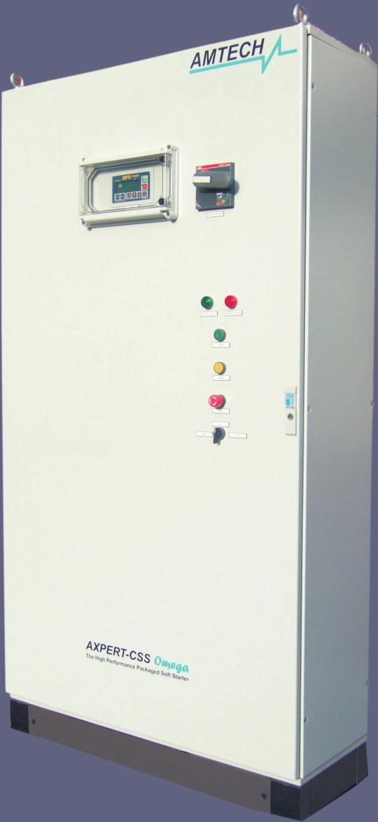
8 FRONT PANEL MOUNTING: RUN PILOT LIGHT If the system is Healthy with no faults, the RUN pilot light (PL-144) will light when the Start Pushbutton is pressed. The Green Light assures that the system is operational. FAULT PILOT LIGHT The Fault pilot light (PL-143) will be lit whenever the Soft Starter experiences a fault. The Red Pilot Light will go out when the fault is reset. START PUSHBUTTON The start pushbutton (PB-135B) is used to start the system. When the system is healthy and starts on pressing this button, the run pilot light lights up. STOP PUSHBUTTON The Stop Pushbutton (PB-135A) will stop the Soft Starter. Since it is a latching-type pushbutton, until it is reset by unlatching the pushbutton, the Soft Starter will not be permitted to start. H-O-A SELECTOR SWITCH The H-O-A selector switch (SS-133) is used to select the Hand mode or Auto mode of operation. In Hand mode, the unit can be operated from panel or terminals. In Auto mode, the unit will operate from the terminal. Axpert-CSS - 7 -
 2- LCD Back-lit Display: 80 characters, 4 lines. 3- Navigation Keys (6 Keys). 4- Start and Stop keys for LOCAL mode.")
9 PARAMETER NAVIGATION AND SETTING The configuration of the Digital Operation Panel (LCD Keypad Module) is shown in the below figure. 1- Status Indicating LEDs (FAULT, RUN and STOP) 2- LCD Back-lit Display: 80 characters, 4 lines. 3- Navigation Keys (6 Keys). 4- Start and Stop keys for LOCAL mode. Pressing the NORM key will show the screen in the figure below. User Selectable four parameters Norm 1 Norm 2 N o r m 0. 0 % L V r y 0. 0 I r 0 0 V o V R a m p, L c l, S t o p Norm 3 Norm 4 Start Mode Start Select Soft starter Status The above figure also indicates the selected start mode, start selection and Soft Starter status. The four user selectable parameters can be configured using parameters A601 ~ A604. When the MODE key is pressed, the last accessed parameter of the last accessed group of Mode-M will appear with its data. The figure below shows parameter M102 of Mode-M and Group-1. Amtech - 8 -
10 Mode-M Group-1 M o d e - M G r o u p - 1 M R - P h a s e C u r r e n t A m p V R a m p, L c l, N o r m a l R u n Parameter Data Parameter Number and Name The first line of the display indicates the present Mode and Group. The second line indicates the parameter number and its function. The third line shows its value. The fourth line shows the present soft-starter status and is displayed except when there is an active fault, or displaying fault history or contact information. Modes & Parameters The parameters are grouped into Modes and Groups according to their functions. The configuration of the parameters is as displayed in the figure below. Each press of the MODE key moves to the next Mode. Pressing it again after reaching to METER mode will return you to the Mode you started from. The GROUP key moves through the different Parameter Group within each Mode. The UP and DOWN keys change the parameters displayed within each Group. Axpert-CSS - 9 -
11 MODE NORM GROUP PARAMETER MODE-M GROUP-1 M101 Output Current MODE-A GROUP-2 M102 R - Phase Current MODE-B GROUP-3 M103 Y - Phase Current MODE-C BASIC PARAMETER PROGRAMMING (OPERATING FROM THE KEYPAD IN LOCAL) Once you are familiar with the parameter navigation system, the next step is to set the basic parameters for your application. To view a specific parameter, first use the MODE key get to the desired mode; Mode s A, B, C contain the parameters that are programmable. Mode M contains the read-only parameters that provide system information such as output voltage and current, input voltage. Then use the GROUP key to reach the desired group within that mode. Use the UP or DOWN keys to reach the desired parameter. During the initial start-up, you must program the key Soft Starter and motor parameters. First press the NORM key to display the Normal screen. Now press the MODE key three times to reach the Mode-B parameters. If Group-1 parameters are not displayed, press the GROUP key until you reach Group-1. Now use the UP or DOWN keys to reach the specific parameter. To change a parameter value, press the ENTER key and the digit flashing can be changed with the UP or DOWN key. Press the GROUP key to change the position of the flashing digit. When the new value has been entered, press the ENTER key again to load the new parameter value. The number will stop flashing. If you press the NORM key instead of the ENTER key, the old parameter value will remain. Amtech
12 HP 100 RPM 1750 MOTOR COMPANY NEMA DESIGN B INS. CLASS B VOLTS 460 S. F PHASE 3 Hz 60 AMPS 114 FRAME 405T The figure to the left shows the information provided on a typical AC motor nameplate. There are several important motor values that will be used to program the soft-starter to provide accurate motor operation and protection. The motor HP will be programmed in kw. To change from HP to kw, multiply by The 100HP shown would be 100 x = 74.6kW. Use the table below for the number of poles. No Load Motor Speed (RPM) Typical Rated Motor Speed (RPM) Number of Poles The Rated Motor Speed on the motor nameplate is an example and each motor may be slightly different since this is the speed the motor is expected to run at full load. Use the actual nameplate value shown on the motor for Rated Motor RPM. For the 1750RPM motor in the example nameplate above, Parameter B105 Motor Rated RPM would be 1750 and B107 Number of Motor Poles would be 4. B103 Motor Rated Current would be 114. Now go to Step 1 and enter motor parameters B101 through B Motor Parameters In Mode-B, Group-1, select parameter B101 and enter the rated input voltage. Now enter the following motor parameters; motor voltage B102, motor rated current B103, motor frequency B104, motor rated rpm B105, motor kw rating B106 and the number of motor poles B Selection of Start Control The unit can be controlled from various places like Digital Operation Panel (Local), Terminal or from PC. Select appropriate start control in A101. Use Digital Operation Panel (Local) during the test operation. A101: Start Control =1: Local Axpert-CSS
13 =2: Terminal =3: Serial Note: - Must be set at 2 Terminal to operate properly 3. Adjusting the ramp time The ramp time needs to be adjusted according to the applications and start/ stop mode. Do not program a long ramp time when using the V-Ramp or I-Ramp start modes. 4. Monitoring the Motor operation. Press the NORM key to display the Normal screen which shows the Motor Current of R phase in Amp and percent load of the AC motor FLA (full load amp) rating, input Vry line voltage and output voltage. These are the default parameters on the Normal screen. There are three ways to view operational parameters to monitor operating values such as input frequency (Hz), motor current of all three phases (Ir, Iy, Ib) (Amps), output voltage, input voltage (AC Volts), motor power factor (PF), output power (kw), and Soft Starter heat sink temperature in both ºC and ºF. A. Press the NORM key and see four monitoring parameters in the Normal screen B. Press the MODE key until you reach the METER Mode and eight monitoring parameters are displayed. C. Press the MODE key until you reach the MODE-M Monitor Parameters. There are five groups of monitoring parameters including the Fault History of the last ten faults and contact information of Amtech Drives. 5. Key Parameters. Listed here are the key parameters used to set up the soft-starter to meet the requirements of most applications. Typically, only a few of these parameters are changed from their default values. Please refer to the Amtech Axpert-Opti torque Soft starter Instruction Manual for the complete parameter listing and Fault Codes. For monitoring, M101 Output Current M102 R-Phase Current Output Current in percentage of full load current of the AC motor. It displays the current of R-Phase in ampere. M103 Y-Phase Current M104 B-Phase Current M105 Output Voltage M106 Input Voltage Vry M107 Input Voltage Vyb M201 Heat sink Temperature M216 Heat sink Temperature It displays the current of Y-Phase in ampere. It displays the current of B-Phase in ampere. It displays the Output Voltage. Input AC Voltage between L1 & L2 Input AC Voltage between L2 & L3 Temperature of the heat sink in ºC. Temperature of the heat sink in ºF. Amtech
14 FLT1 FLT10 Fault History Provides fault history for 10 faults and 4 values at time of each fault. The Fault History is located in Mode M Group 4. The unit is shipped with some important parameters, which are required as per the logic requirement. There are some parameters (as indicated below) need to be set by the user based on the application requirement. A101 Start Control A102 Maintained Start/Stop A104 Start Mode Selection A105 Stop Mode Selection A106 V-Ramp Up Time1 A107 V-Ramp Down Time1 B101 B107 Motor Parameters B108 SS Connection Type B301 I-Limit Level B302 I-Limit Time C101 PSI 1 C111 Prog. Relay 1 C112 Prog. Relay 2 C113 Prog. Fault Relay Terminal is selected for the start control. The unit is programmed for maintained start. The unit is shipped with the default V-Ramp Start, but can be changed as per the application requirement by the user. The unit is shipped with the default coast-to-stop mode, but can be changed as per the application requirement. Sets the ramp up time for V-Ramp Start and Jogging. Set this before starting as unit is shipped with the default ramp up time. Sets the ramp down time for V-Ramp Stop. Not applicable if the stop mode is coast-to-stop. Set as per the application requirement if other than coastto-stop mode is selected. Key motor values that must be programmed at startup. The unit is shipped with the default Inline type Sets the current limit as a % of motor rated current. Normally set to 350%. Sets the time limit for which the current limit can be active. Unit will trip if the total time of current limit operation exceeds the set time. Normally set to 10 seconds. The unit is shipped with option-6: Bypass contactor fault. This is used for feedback of bypass contactor. If the bypass contactor fails to operate, the unit will give fault. The unit is shipped with the default option-3: Run. This is used for the RUN indication on the panel. The unit is shipped with the default option-4: Top of ramp. This is used to operate the bypass contactor after the motor ramps to the full speed. The unit is shipped with the default option-6: Fault. This is used for the fault indication. Axpert-CSS
15 Below are some important parameters, which need to be set as per the application requirement. A301 I-Ramp Up Time Sets the ramp up time for I-Ramp Start. A302 Initial Current A401 T-Ramp Up Time A402 Initial Torque A403 Torque Limit A406 T-Ramp Down Time A407 End Torque B307 I-Trip Level B309 Parameter Lock B310 Change Password Sets the initial current level for I-Ramp Start. Sets the ramp up time for T-Ramp Start. Sets the initial torque level for T-Ramp Start. Sets the torque limit for T-Ramp Start. Sets the ramp down time for T-Ramp Stop. Sets the end torque level at stop as a % of motor nominal torque. This parameter sets the threshold of the instantaneous over current trip as % of motor rated current. Password to control parameter changes. Allows selection of user selectable password. B311 Default Value Load Multiple functions; reset parameters to default, store user parameters, load user parameters from memory, clear fault history. C Vout 1 2 Selects function of the two 0-10VDC Analog Outputs. C Iout 1 2 Selects function of the two 4-20mA Analog Outputs. Amtech
16 6. Start-Up Parameter Check List. Shown below is a list of the typical parameters used for general Soft Starter applications. Please write in the specific User s settings that make your installation unique. This information will be invaluable in the future for Soft Starter duplication, troubleshooting or replacement. Parameters Default User s Values B101 Rated Input Voltage 460V VAC B102 Motor Voltage 460V VAC B103 Motor Current M301 Amps B104 Motor Frequency 50Hz Hz B105 Motor Speed 1500RPM RPM B106 Motor Output M302 kw B107 Motor Poles 4 B108 SS Connection Type 1: Inline Start and Stop Control Method Parameters Default User s Values A101 Start Control Local A102 Maintained Start/Stop Maintained A104 Start Mode Selection V-Ramp Start A105 Stop Mode Selection Coast to Stop Axpert-CSS
17
RVS-DN Digital Reduced Voltage Motor Starter
 RVS-DN Digital Reduced Voltage Motor Starter Specification Guide Specification Guide Contents 1.0 Introduction 2.0 Specifications 2.1 Standard Performance Features 2.2 Standard Protection Features 2.3
RVS-DX Digital Reduced Voltage Motor Starter
 RVS-DX Digital Reduced Voltage Motor Starter Specification Guide Specification Guide Contents 1.0 Introduction 2.0 Specifications 2.1 Standard Performance Features 2.2 Standard Protection Features 2.3
Installation and Maintenance Instructions. World Leader in Modular Torque Limiters. PTM-4 Load Monitor
 World Leader in Modular Torque Limiters Installation and Maintenance Instructions PTM-4 Load Monitor 1304 Twin Oaks Street Wichita Falls, Texas 76302 (940) 723-7800 Fax: (940) 723-7888 E-mail: sales@brunelcorp.com
 Standard Features 200-600V, 50/60Hz input power supply Built-in run rated (AC1) By-pass contactor up to 820 A * Rated 450% current Conformal coated circuit board Voltage ramp or current limit start modes
University of Houston Master Construction Specifications Insert Project Name SECTION ELECTRONIC VARIABLE SPEED DRIVES PART 1 - GENERAL
 SECTION 23 04 10 ELECTRONIC VARIABLE SPEED DRIVES PART 1 - GENERAL 1.1 RELATED DOCUMENTS: A. The Conditions of the Contract and applicable requirements of Division 1, "General Requirements", and Section
Observe all necessary safety precautions when controlling the soft starter remotely. Alert personnel that machinery may start without warning.
 Introduction OPERATING INSTRUCTIONS: MCD REMOTE OPERATOR Order Codes: 175G94 (for MCD 2) 175G361 + 175G9 (for MCD 5) 175G361 (for MCD 3) 1. Introduction 1.1. Important User Information Observe all necessary
USERS MANUAL MCD REMOTE OPERATOR
 USERS MANUAL MCD REMOTE OPERATOR Order Code: 175G9004, 175G3061 Contents Contents Introduction...2 Important User Information...2 General Description...2 Symbols Used in this Manual...2 Installation...3
TRIPS AND FAULT FINDING
 WWW.SDS.LTD.UK 0117 9381800 Trips and Fault Finding Chapter 6 6-1 TRIPS AND FAULT FINDING Trips What Happens when a Trip Occurs When a trip occurs, the drive s power stage is immediately disabled causing
GPH2 Combination Soft Starters
 Combination Soft Starters The Combination Soft Starter is a NEMA 4/12 Enclosed industrial general purpose AC motor soft starter package. It is designed for simple and quick installation and start-up, requiring
Burden Fuse Rating Resistor SAF / SAK6 1NM 10mm M8 12NM SAF / SAK10 2NM 16mm M8 12NM
 Contents Section Page 1.0 Introduction 1 2.0 Specification 1-4 3.0 Installation 5-8 4.0 Programming 9-10 5.0 Menus 10-12 6.0 Fault Finding/Diagnostics 12-13 7.0 Communication 13 8.0 Setting Up 13-16 1.0
SECTION MOTOR CONTROL
 SECTION 26 24 19 MOTOR CONTROL PART 1 - GENERAL 1.1 SECTION INCLUDES A. Manual motor starters B. Magnetic motor starters C. Combination magnetic motor starters D. Solid-state reduced voltage motor starters
1333 (SERIES B & C) TROUBLESHOOTING GUIDE
 TROUBLESHOOTING GUIDE") 1333 (SERIES B & C) TROUBLESHOOTING GUIDE Preventive Maintenance: Problems with Your Drive? Bulletin 1333 is convection or fan cooled by air flowing through the heat sink slots. The slots must never be
1333 (SERIES B & C) TROUBLESHOOTING GUIDE Preventive Maintenance: Problems with Your Drive? Bulletin 1333 is convection or fan cooled by air flowing through the heat sink slots. The slots must never be
DRAFT 1400HP 1000HP 100HP. Reduced Voltage Solid State Starters. Softstarters SOFT. PF Controller PCS Controller PDS Controller V 1...
 100HP 400HP 700HP 1000HP 1400HP PCS Softstarter Controller IN-rail mountable microprocessor controller for 3-phase motors up to 480A (3...85A din-rail mountable) Provides three different starting modes
Features and Benefits. Control Features
 Features and Benefits AC induction motors have become increasingly dominant in industrial facilities worldwide. Manufacturers faced with increasing pressure to control costs have recognized that motor
SE-3SCR-LM MANUAL MOTOR LOAD MANAGER
 3714 Kinnear Place Saskatoon, SK Canada S7P 0A6 Ph: (306) 373-5505 Fx: (306) 374-2245 www.littelfuse.com/relayscontrols SE-3SCR-LM MANUAL MOTOR LOAD MANAGER MARCH 5, 2013 REVISION 4 MOTOR LOAD MANAGER
RVS-AX Instruction Manual
 RVS-AX Analog Soft Starter 8-170A, 220-600V Instruction Manual Ver. 10/11/2009 2 Table of Content RVS-AX Instruction Manual 1. TABLE OF CONTENT 1. Table of Content...2 2. Safety & Warnings...3 2.1 Safety...3
MCD 200 Series Soft Starters
 MCD 200 Series Soft Starters AC motors often cause one or more serious problems during startup acceleration. MCD 200 Series electronic soft starters control motor current to provide a smooth start. When
Softstarters. Softstarters Type SSM Medium voltage ,800V 1
 Medium voltage 2300 13,800V 1 Description Fused disconnect switch with blown fuse indicators and door safety interlocks rated for load break/fault make with automatic grounding arm Inline isolation vacuum
825-P Modular Protection System for motors Specification Guide
 Specification Guide 1.0 General 1.01 The motor protection relay shall have a current operating range of 0.5 and 5000 amperes. 1.02 The motor protection relay shall provide current measurement-based protection
CTi Automation - Phone: Fax: Web:
 CTi Automation - Phone: 800.894.0412 - Fax: 208.368.0415 - Web: www.ctiautomation.net - Email: info@ctiautomation.net The control & protection you expect in an innovative soft starter design... Flexibility
Application Description
 -14 Type, Intelligent Technologies (IT.) Soft Starters February 2007 Contents Description Page Type, Intelligent Technologies (IT.) Soft Starters Product Description....... -14 Application Description....
Sensorless Vector Drives
 STANDARD PRODUCTS Sensorless Vector Drives SG SERIES STANDARD DUTY / HEAVY DUTY RATINGS Variable Torque: 7.5 to 700HP @ 460V 7.5 to 40HP @ 2V Standard Duty: 7.5 to 600HP @ 460V 7.5 to 40HP @ 2V Heavy Duty:
Application Engineering Europe
 Date of last update: Feb-12 Ref: D7.8.4/0112-0212/E Application Engineering Europe CORESENSE DIAGNOSTICS FOR STREAM REFRIGERATION COMPRESSORS 1/17 1 Introduction CoreSense is an ingredient brand name for
300% Motor full load amps at 80 seconds, 400% Motor full load amps at 35 seconds
 Digital Soft Start Controls 9 thru 900 Amps 208-460V 50/60 Hz. 9 thru 900 Amps 208-575V 50/60 Hz. Applications: Controlled ramp start and stop, minimize spillage in material handling, reduced water hammer
Continuing Education Course #206 Introduction to Designing Machine Control Systems Part 2
 1 of 5 Continuing Education Course #206 Introduction to Designing Machine Control Systems Part 2 1. Continuing to answer the following questions indicates that you understands that the presented material
A. Provide variable frequency drives to operate variable torque loads as shown on the Drawings and as specified herein.
 DIVISION 23 HEATING, VENTILATING, AND AIR CONDITIONING (HVAC) SECTION 23 90 71 PART 1 GENERAL 1.01 DESCRIPTION A. Provide variable frequency drives to operate variable torque loads as shown on the Drawings
Model ESV Uninterruptible Power System 1.5 KVA/KW KVA/KW Single Phase
 Model ESV Uninterruptible Power System 1.5 KVA/KW - 14.0 KVA/KW Single Phase 1.0 General General Specification This specification describes the features and design of an on-line, dual conversion, uninterruptible
SDS Enclosed Star-Delta Starter User Guide
 SDS Enclosed Star-Delta Starter User Guide (7.5kW~90kW) V2.0.0 PLEASE NOTE: AS STANDARD AND UNLESS OTHERWISE SPECIFIED, THIS PRODUCT IS EQUIPPED WITH A BASIC LOW INTEGRITY EMERGENCY STOP CIRCUIT STOPPING
Motor Starters. Reduced Voltage. Reduced Voltage Motor Starters 1. Contents
 1 January 00 Reduced Voltage Motor Starters Contents Description Page Open Type S7, Intelligent Technologies (IT.) Soft Starters Product Description............................................. Application
Installation & Operation Manual
 Installation & Operation Manual SECO SE 2000 Series DC Motor Controller 1 Through 5 HP 115/230 VAC 1 Phase Input TABLE OF CONTENTS Section Page 1.0 GENERAL INFORMATION... 3 1.1 Controller... 4 1.2 Specifications...
DC Variable Speed Drive Panel
 DC Variable Speed Drive Panel Installation, Operation & Maintenance Instruction Manual Bulletin #: CC-IOM-0103-D Manufacturers of Quality Pumps, Controls and Systems ENGINEERED PUMP OPERATIONS 2883 Brighton
SSW03 Soft Starter APG2009.indd 69 5/26/09 8:55 AM
 www.we.net WEG are built to match the ruedness and reliability of WEG motors, providin a complete and cost effective solution. Full microprocessor based control allows easy adjustment throuh the keypad
Cutler-Hammer. Instructions for Installation, Operation, and Maintenance of the AMPGARD Reduced Voltage Soft Starter
 Operation, and Maintenance of the Instruction Bulletin Read and understand these instructions before attempting any installation, operation, or maintenance of the. This equipment shall be installed and
BT300 HVAC Drives Conventional Bypass (C-Bypass) Options
 Options") BT300 HVAC Drives Conventional Bypass (C-Bypass) Options Description The BT300 Conventional Bypass is a companion package for the family of BT300 HVAC Drives. For information on the family of BT300 HVAC
BT300 HVAC Drives Conventional Bypass (C-Bypass) Options Description The BT300 Conventional Bypass is a companion package for the family of BT300 HVAC Drives. For information on the family of BT300 HVAC
A problem with the motor windings. A phase loss on mains terminals L1, L2, or L3 during run mode. Parameter 2-3 Current Imbalance Delay.
 10 Troubleshooting When a protection condition is detected, the VLT Soft Starter MCD 500 writes this condition to the event log and may also trip or issue a warning. The soft starter response depends on
MaxPak Plus Analog DC V S Drive
 Three-Phase 3-600 HP non-regenerative and 5-150 HP regenerative drives Designed to accommodate a wide range of industrial requirements, the DC V S Drive has been widely applied worldwide. Selected ratings
HIB Enclosed Inverter User Guide
 HIB Enclosed Inverter User Guide (0.75kW~22kW) V1.2.0 Contents 1 Safety information...1 2 Technical Data...2 3 Motor Connection...4 4 Operation...5 5 Single phase circuit diagram...7 6 Three phase circuit
GPH2. Soft Starters. Applications. Standard Features. Centrifugal Pumps Screw Compressors Centrifugal Fans Wood Chipper Veneer Lathe Saw Conveyor
 The Combination Soft is a NEMA 4/12 Enclosed industrial general purpose AC motor soft starter package. It is designed for simple and quick installation and start-up, requiring only input power and output
MODEL 520 REMOTE START ENGINE MANAGEMENT SYSTEM
 MODEL 520 REMOTE START ENGINE MANAGEMENT SYSTEM DSE 520 ISSUE 4 4/4/02 MR 1 TABLE OF CONTENTS Section Page INTRODUCTION... 4 CLARIFICATION OF NOTATION USED WITHIN THIS PUBLICATION.... 4 1. OPERATION...
Installation Instructions
 Installation Instructions Power Exhaust Part Numbers: CRPWREXH07A00 THROUGH CRPWREXH079A00 Conversion Package Numbers: CRPECONV005A00, CRPECONV006A00 CONTENTS Page SAFETY CONSIDERATIONS......................
Electronic Bypass Controller
 Installation and Commissioning Guide Electronic Bypass Controller HVAC Drive H300, Unidrive M200 and Unidrive M400 Part Number: PSD-H300BP-ICG Issue: 5.0 Contents Section 1 - Introduction... 5 Section
CURTIS TOLEDO. AF Series Compressors VS models with VFD WARNING
 AUGUST, 2004 REV.A CURTIS TOLEDO OPERATOR S MANUAL SUPPLEMENT AF Series Compressors VS models with VFD WARNING Personal injury and/or equipment damage will result by failing to pay attention to the vital
Installation Instructions & Users Manual
 Installation Instructions & Users Manual UTILITY/ BUILDING INPUT 120 VAC ( OPTION) 15-20A N L CONTROL BOARD G SECURITY LIGHTING POWER SUPPLY (OPTION) CHARGER- POWER SUPPLY ASSBY XFMR (OPTION) CBM MODEL
HGM1780 AUTOMATIC GENERATOR MODULE CONTENT 1. SUMMARY PERFORMANCE AND CHARACTERISTICS SPECIFICATION OPERATION...
 CONTENT 1. SUMMARY...4 2. PERFORMANCE AND CHARACTERISTICS...4 3. SPECIFICATION...5 4. OPERATION...6 4.1. DISPLAY PANEL...6 4.2. LCD ICON INSTRUCTION...7 4.3. DISPLAY INSTRUCTIONS...7 4.4. DISPLAY DESCRIPTION...8
CONTROL FEATURES AVAILABLE OPTIONS
 Vari Speed A2000 TABLE OF CONTENTS Control Features Options Application Data Operating Condition s Control Ratings Chart Mounting Dimensions Installation and Wiring Typical Wiring Diagram Schematic (Block
Fincor Series 2230 MKII/2240
 Fincor Series 2230 MKII/ Fincor Series 2200 regenerative drives are ideal for your more demanding applications. They feature flexibility with ratings up to 5 horsepower. The Series 2230 MKII offers new
Motor Controllers AC Semiconductor Motor Controller Type RSHP Flexy
 otor Controllers AC Semiconductor otor Controller Type RSHP Flexy Soft starting and stopping of 3-phase squirrel cage motors Low surge and vibration-free starting User-selected ramping profiles Integral
WARREN COUNTY, N.Y. M/E REFERENCE A. Submit manufacturer's product data on all motors and adjustable speed drives.
 SECTION 230513 - MOTORS AND ADJUSTABLE SPEED DRIVES PART 1 - GENERAL 1.1 DESCRIPTION A. Provide labor, materials, equipment and services as required for the complete installation designed in Contract Documents.
1.2. Reduced Voltage Motor Starters. Contents Description Type S611, Solid-State Soft Starters... Type S801+, Soft Starters. Solid-State Starters
 .2 Type S80+, Soft Starters Contents Description Type S6, Solid-State Soft Starters........... Type S80+, Soft Starters Operation............................. Features.............................. Benefits...............................
HGM1780. Automatic Genset Controller USER MANUAL. Smartgen Technology
 HGM1780 Automatic Genset Controller USER MANUAL Smartgen Technology Smartgen Technology Co., Ltd No. 28 Jinsuo Road Zhengzhou Henan Province P. R. China Tel: 0086-371-67988888/67981888 0086-371-67991553/67992951
UL/NEMA Type 1 & Type 12 FRENIC-HVAC Combination VFD
 UL/NEMA Type 1 & Type 12 FRENIC-HVAC Combination VFD Safety Precautions Read this manual thoroughly before proceeding with installation, connections (wiring), or maintenance and inspection. Ensure you
User s Manual. ACH550-CC/CD Packaged Drive with Classic Bypass Supplement for ACH550-UH HVAC User s Manual
 User s Manual ACH550-CC/CD Packaged Drive with Classic Bypass Supplement for ACH550-UH HVAC User s Manual ii ACH550-CC/CD Packaged Drive with Classic Bypass ACH550 Drive Manuals GENERAL MANUALS ACH550-UH
AuCom - Soft Starters
 AuCom - Soft Starters AuCom - Soft Starters 208 CSXi Compact Soft Starters AuCom s new CSX Series includes two ranges. Users can choose between a simple soft start control device and an advanced soft start
300% Motor full load amps at 80 seconds, 400% Motor full load amps at 35 seconds
 Digital Soft Start Controls Soft Starters & 9 thru 900 s 208-460V 50/60 Hz. 9 thru 900 s 208-575V 50/60 Hz. Farm Duty Applications: Controlled ramp start and stop, minimize spillage in material handling,
Flight Systems. Replacement for KASSEC DESCRIPTION
 DESCRIPTION The is a universal generator controller that will start, stop, and provide engine protection for most generators. Universal replacement for both the 90353 and 90354 KASSEC Compatible with most
Overvoltage Suppression F7 Drive Software Technical Manual
 Overvoltage Suppression F7 Drive Software Technical Manual Software Number: VSF11015X, Drive Models: CIMR-F7UXXXXXX-062, CIMR-F7U40750F-145. Document Number: TM.F7SW.062, Date: 09/17/2010, Rev: 10-09 This
Quick guide. Plug-in fans GPPM with FC101_106 August 2014
 Quick guide Plug-in fans GPPM with FC101_106 August 2014 Fläkt Woods permanent magnet motors and speed controllers for plug fans GPPM 1. General Fläkt Woods offers a wide range of permanent magnet motors
HPS2DB Serial Softstarter Operation Manual
 HPS2DB Serial Softstarter Operation Manual Hapn Electric Co.,LTD. HPS2DB Softstarter Table of Contents Page Subject 2 Starter Selection 4 Installation 5 Control Terminals 6 Application diagram 10 Parameters
GENSET CONTROL MODULE LEVEL 1 A121CM / A241CM. Special logic to re-establish cranking following a false start.
 Technical Data Sheet GENSET CONTROL MODULE LEVEL 1 A121CM / A241CM Features: Models for both 12V and 24V systems. One model for both spark ignition and diesel engines. 5-alarm light outputs with lamp-test
1/6 through 5 HP Adjustable Speed, DC Motor Controllers
 1/6 through 5 HP Adjustable Speed, DC Motor Controllers 1/6-5 HP 115 or 230 V, Single Phase - Reconnectable Four Quadrant Regenerative Selectable Deadband AC Line Starting DC Tachometer Feedback Run Contact
User s Manual. ACS550-CC Packaged Drive with Bypass Supplement for ACS550-01/U1 Drives User s Manual
 User s Manual ACS550-CC Packaged Drive with Bypass Supplement for ACS550-01/U1 Drives User s Manual ii ACS550-CC Packaged Drive with Bypass ACS550 Drive Manuals GENERAL MANUALS ACS550-01/U1 Drives User's
GENSET CONTROL MODULE A121A / A241A
 Technical Data Sheet GENSET CONTROL MODULE A121A / A241A Features: Models for both 12V and 24V systems. One model for both spark ignition and diesel engines. 4-alarm light outputs with lamp-test provisions.
SED2. Variable Frequency Drives. with Conventional Bypass Options. Variable Frequency Drives. Description. Features F-9.
 SED2 with Conventional Bypass Options Important Note: VD products are only available through authorized distribution channels. To locate an authorized distributor, please contact a Siemens Building Technologies
Series 5 Inverter OPEN CHASSIS MOUNT - SINGLE PHASE INPUT. For Catalog Nos. ID56F50-CO, ID5601-CO & ID5602-CO
 Series 5 Inverter OPEN CHASSIS MOUNT - SINGLE PHASE INPUT For Catalog Nos. ID56F50-CO, ID5601-CO & ID5602-CO 1/17 Installation & Operating Manual MN781 Table of Contents Chapter 1 Introduction Introduction...
Electromagnetic Industries LLP
 GROUND FAULT CURRENT DETECTION GFM Relay (Model 252 & 262) The GFM system is designed for electrical protection, not for personnel protection Application: These Class 1 (Model GFM) Ground Fault protection
SECTION MICROPROCESSOR TRIP UNITS FOR LV CIRCUIT BREAKERS. This section is organized as indicated below. Select desired Paragraphs.
 SECTION 16904 MICROPROCESSOR TRIP UNITS FOR LV CIRCUIT BREAKERS PART 2 PRODUCTS 01 MANUFACTURERS A. B. C. Eaton * * The listing of specific manufacturers above does not imply acceptance of their products
PBA Series Prelube Controls
 VARNA Products Engineered Innovation PBA Series Prelube Controls Simple, Compact, Industrial Full featured control for running prelube from the control or from a remote station Easy internal wiring connections
TOWER MAXI T SINGLE CONVERSION ON LINE UPS SYSTEMS
 INSTRUCTION MANUAL TOWER MAXI T SINGLE CONVERSION ON LINE UPS SYSTEMS September 2000 TOWER UPS DISTRIBUTION (PTY) LTD 1 1. INTRODUCTION T A B L E O F C O N T E N T S 1.1 General Description... 3 1.2 Features...
17429X.00 SERIES MODELS:
 LEESON ELECTRIC MOTORS, GEARMOTORS AND DRIVES R User s Manual 17429X.00 SERIES MODELS: 174298.00 174299.00 PWM REGENERATIVE DC TO DC DRIVES II Table of Contents 17429X.00 Drives...............................................................
NEMA 1, NEMA 4X and Chassis Mount Adjustable Speed Controls for DC Motors
 Made in the U.S.A. NEMA 1, NEMA 4X and Chassis Mount Adjustable Speed Controls for DC Motors Nema Enclosed DC Control Specifications Catalog Number BC140 or Features BC138 BC139 BC140-FBR BC154 BC160 BCWD140
INSTALLATION INSTRUCTIONS FOR SYMCOM'S MODEL 777-HVR-SP ELECTRONIC OVERLOAD RELAY
 CONNECTIONS INSTALLATION INSTRUCTIONS FOR SYMCOM'S MODEL 777-HVR-SP ELECTRONIC OVERLOAD RELAY BE SURE POWER IS DISCONNECTED PRIOR TO INSTALLATION!! FOLLOW NATIONAL, STATE AND LOCAL CODES! READ THESE INSTRUCTIONS
Phoenix DX Sensorless AC Vector Drive. 3 HP to 3500 HP
 Phoenix DX Sensorless AC Vector Drive 3 HP to 3500 HP Standard Features: * PRECISE CONTROL OF MOTOR SPEED AND TORQUE * BI-DIRECTIONAL FLYCATCHER (CATCH SPINNING MOTOR) * EASY TO USE, SIMPLE SETUP * POWER
Solar Hybrid Power Generating System CPS1200EOH12SC CPS2200EOH24SC CPS3000EOH24SC. User s Manual K01-C
 Solar Hybrid Power Generating System CPS1200EOH12SC CPS2200EOH24SC CPS3000EOH24SC User s Manual K01-C000304-02 2 TABLE OF CONTENTS 1 IMPORTANT SAFETY INSTRUCTIONS..4 2 INSTALLATION....5 2-1 Unpacking...5
PORTABLE CURRENT SOURCE FOR CIRCUIT BREAKER AND MOTOR OVERLOAD TESTING INSTRUCTION MANUAL PI-250B. Release 1.0 April 5, 2013
 PORTABLE CURRENT SOURCE FOR CIRCUIT BREAKER AND MOTOR OVERLOAD TESTING INSTRUCTION MANUAL PI-250B Release 1.0 April 5, 2013 Electrical Test Instruments, Inc. 1301 Avondale Road, Suite J New Windsor, MD
ADJUSTABLE FREQUENCY CRANE CONTROLS
 IMPULSE G+ MINI ADJUSTABLE FREQUENCY CRANE CONTROLS The IMPULSEG+ Mini from Magnetek continues our history of providing the most reliable and cost-effective adjustable frequency crane controls available.
DENVER PUBLIC SCHOOLS DESIGN AND CONSTRUCTION STANDARDS This Standard is for guidance only. SECTION MOTORS, STARTERS & DRIVES
 PART 0 DESIGN STANDARDS 0.01 GENERAL DESIGN GUIDELINES A. Coordinate starter needs for mechanical equipment prior to 50% CD and confirm again for 100% CD submittal. B. Coordinate temperature controls requirements
Quick Start Guide TS 910
 Quick Start Guide TS 910 DANGER HAZARD OF ELECTRICAL SHOCK, EXPLOSION, OR ARC FLASH Read and understand this quick start guide before installing and operating the transfer switch The installer is responsible
Generator Start Control Module
 Generator Start Control Module Part# GSCM-mini-i ATKINSON ELECTRONICS, INC. 14 West Vine Street Murray, Utah 84107 Contact cbdsales@atkinsonel.com for the proper hookup diagram. Please include the generator
2.1 Warnings & Agency Approvals Electrical Connections - Specifications Standard Wiring Configurations...2 4
 CHAPTER ELECTRICAL 2 INSTALLATION Contents of this Chapter... 2.1 Warnings & Agency Approvals..................2 2 2.1.1 Isolation..............................................2 2 2.1.2 Electrical Power
DRIVE STARTUP MANUAL. Magnetek HPV900-S2 Drive. PM Motor Installation
 DRIVE STARTUP MANUAL Magnetek HPV900-S2 Drive PM Motor Installation CONTROLLER GROUNDING REQUIREMENTS NOTE For the controller to function properly it is very important to provide proper building ground
Filtered PWM Speed Control for Permanent Magnet DC Motors
 Instructions for Installation and Operation Filtered PWM Speed Control for Permanent Magnet DC Motors Model 0794 Speed and Direction Control up to 5/8 HP NEMA-1/IP-20 Specifications Product Type:... WPM-2148E1
INSTALLATION INSTRUCTIONS DNLOWAMB015A00, DNLOWAMB016A00
 INSTALLATION INSTRUCTIONS DNLOWAMB015A00, DNLOWAMB016A00 and DNLOWAMB017A00 Accessory Low Ambient Motor Controller For Models PGS/PAS240, 300 and PGE/PAE240 These instructions must be read and understood
HGM7100N SERIES (HGM7110N/7120N) GENSET CONTROLLER USER MANUAL
 GENSET CONTROLLER USER MANUAL") HGM7100N SERIES (HGM7110N/7120N) GENSET CONTROLLER USER MANUAL SMARTGEN (ZHENGZHOU) TECHNOLOGY CO., LTD. Chinese trademark English trademark SmartGen make your generator smart SmartGen Technology Co.,
HGM7100N SERIES (HGM7110N/7120N) GENSET CONTROLLER USER MANUAL SMARTGEN (ZHENGZHOU) TECHNOLOGY CO., LTD. Chinese trademark English trademark SmartGen make your generator smart SmartGen Technology Co.,
ARM V FDBK ENSURE MOTOR IS NOT ROTATING DURING POWER UP STILL FAULTS? YES ENSURE ARMATURE WIRING IS ISOLATED FROM ANY OTHER POWER LEADS STILL FAULTS?
 ARM V FDBK ENSURE MOTOR IS T ROTATING DURING POWER UP This fault can only happen in the first 3 seconds after power up. The processor looks at the armature voltage. The voltage needs to be near 0. Possible
SB 2000 PUSH TO SEARCH NEXT STAG E. Aerotech, Inc. FORM: QM 1320
 Inlet Controller SB 2000 USER'S MANUAL AUTO OPEN MANUAL PUSH TO SEARCH NEXT STAG E CLOSE Aerotech, Inc. FORM: QM 1320 4215 Legion Dr. Mason, MI 48854-1036 USA Rev. 3, Sept. 1997 Ph. (517) 676-7070 Fax
SECTION MOTORS AND VARIABLE FREQUENCY DRIVES
 PART 1 GENERAL 1.1 RELATED DOCUMENTS A. Related Sections: 1. Section 15050 - Basic Mechanical Requirements. 2. Section 15051 - Motors. 3. Section 15185 - Hydronic Pumps. 4. Section 15625 - Centrifugal
DC3E Non-Regenerative DC Drive User Guide 1/4 to 2 HP, 115/230 VAC M/N DC3N-12D AI M/N DC3N-12D-4X-010-AI
 250-0287-rev2.qxd 3/12/01 10:27 AM Page a DC3E Non-Regenerative DC Drive User Guide 1/4 to 2 HP, 115/230 VAC M/N DC3N-12D-00-010-AI M/N DC3N-12D-4X-010-AI Instruction Manual D2-3452-1 250-0287-rev2.qxd
VLT Soft Starter MCD 100, MCD 201, MCD 202, MCD 3000
 VLT Soft Starter MCD 100, MCD 201, MCD 202, MCD 3000 Soft starts Protect Gear, Goods, Equipment and Environment An AC motor switched directly on to the mains power supply will struggle to reach its nominal
USER'S GUIDE. WiseHP11 SINGLE PHASE HIGH PRECISION AVR SERVO-MOTOR AUTOMATIC VOLTAGE STABILIZER
 USER'S GUIDE WiseHP11 SINGLE PHASE HIGH PRECISION AVR SERVO-MOTOR AUTOMATIC VOLTAGE STABILIZER LEN.MAN.STA.145 Rev.5.00/2010 CONTENTS 1. SAFETY INSTRUCTIONS 1 2. INTRODUCTION 2 3. FRONT PANEL AND INSIDE
CORESENSE DIAGNOSTICS FOR STREAM REFRIGERATION COMPRESSORS
 Date of last update: Apr-15 Ref: D7.8.4/0112-0415/E Application Engineering Europe CORESENSE DIAGNOSTICS FOR STREAM REFRIGERATION COMPRESSORS CoreSense Diagnostics for Stream Refrigeration Compressors...
Induction Power Supplies
 Induction Power Supplies 7.5kW; 135 400kHz 480V version (Integral Heat Station) User s Guide Model 7.5-135/400-3-480 SMD Control Brds Rev. D 5/08 Table of Contents 1. Specifications and features...3 2.
MAGNETIC MOTOR STARTERS
 Chapter 6 MAGNETIC MOTOR STARTERS 1 The basic use for the magnetic contactor is for switching power in resistance heating elements, lighting, magnetic brakes, or heavy industrial solenoids. Contactors
Quick Start Guide TS 910 & TS 920
 Quick Start Guide TS 910 & TS 920 DANGER HAZARD OF ELECTRICAL SHOCK, EXPLOSION, OR ARC FLASH Read and understand this quick start guide before installing and operating the transfer switch The installer
ACC Series Power Conditioner OPERATION & INSTALLATION MANUAL
 ACC Series Power Conditioner OPERATION & INSTALLATION MANUAL PHASETEC digital power conditioners are designed to safely operate electrical equipment in the harshest power quality environments. With a wide
User s Manual. ACS550-CC Packaged Drive with Bypass Supplement for ACS550-01/U1 Drives User s Manual
 User s Manual ACS550-CC Packaged Drive with Bypass Supplement for ACS550-01/U1 Drives User s Manual ii ACS550-CC Packaged Drive with Bypass ACS550 Drive Manuals GENERAL MANUALS ACS550-01/U1 Drives User's
GPU Equipment Operating Instructions Table of Contents
 GPU Equipment Operating Instructions Table of Briggs & Stratton Model: 30439 Davco Model: GP28R under construction Foxtronics Model: PR-2000-T7S GUINAULT MODEL: GA90V133 HOBART MODEL: JET EX-2, EX-3, EX-4,
E.S.P. Embedded Sensing Probes for Motor Brushes
 E.S.P. Embedded Sensing Probes for Motor Brushes 2/13 Installation & Operating Manual MN609 Any trademarks used in this manual are the property of their respective owners. Important: Be sure to check www.baldor.com
Solid State Starters. Standard and Combination Packages. NEMA 4/ 12 Units are Designed for Crusher Applications
 Solid State Starters Standard and Combination Packages Solid State Starters provide ramped starting for induction motors by either reduced voltage or torque control at start. Either method creates a soft
Generator Start Control Module
 Generator Start Control Module Part# GSCM-mini-o ATKINSON ELECTRONICS, INC. 14 West Vine Street Murray, Utah 84107 Contact cbdsales@atkinsonel.com for the proper hookup diagram. Please include the generator