BLOWER VACUUM SWITCH FAILED OPEN
|
|
|
- Ellen Bates
- 5 years ago
- Views:
Transcription
1 F1 F1
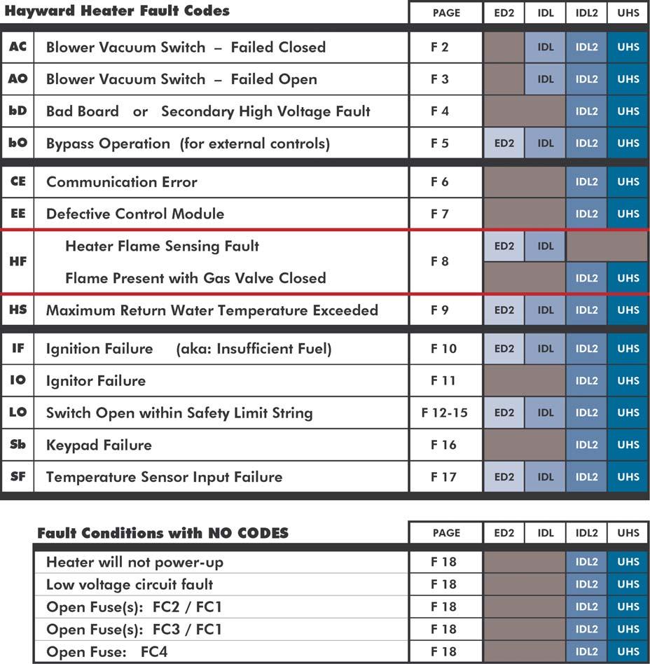
2 AC BLOWER VACUUM SWITCH FAILED CLOSED AC BLOWER VACUUM SWITCH FAILED CLOSED UHS If the blower vacuum switch is closed before blower start-up, the control module will not start the blower. Pre-check is executed by the control module. A. Disconnect the blower plug from the control module. IDL2 IDL F2 With the heater off, measure the control module receptacle s continuity across pins 1 and 2 (UHS, IDL2 & IDL) and pins 3 & 4 (IDL2 & IDL only). If either is closed, replace the control module. B. If the relay is open, check the vacuum switch. If it is closed, the blower vacuum switch failed and must be replaced. AC Blower Vacuum Switch Failed Closed Blower Vacuum Switch Control Module. F2


3 AO BLOWER VACUUM SWITCH FAILED OPEN AO BLOWER VACUUM SWITCH FAILED OPEN UHS If the blower vacuum switch opens unexpectedly during operation, the heater will shut down and attempt to re-light if there is still a call for heat. If the blower vacuum switch does not close after the blower starts, the control will stop the ignition trial & go into lockout. The blower will continue to run for post-purge. Automatic reset is immediate after the switch closes. Blower Blower Vacuum Switch Control Module/Ignition Board Gray Vacuum Tubing A. Check for faulty vacuum switch tubing and replace if necessary. B. Check for faulty vacuum switch wiring or connection. Wire harness terminals must be securely fastened to spade terminals on vacuum switch. IDL2 D. Check for defective vacuum switch by disconnecting blower plug from control module. Measure resistance across blower windings. Winding resistance across lead should be in the following range: IDL: Black to White ohms Red to White ohms IDL2: Black to White ohms Red to White ohms UHS: Red to White 8-9 ohms AO If measured values vary substantially from these values, the blower is defective and should be replaced. E. Check for a defective blower relay by disconnecting blower plug from the control module. Place heater in Pool or Spa mode. Lower set point temperature to generate call for heat. During pre-purge period, measure for 120VAC across pins 1 and 2 (UHS & IDL2) or L1 & IND low (IDL). IDL If 120VAC is not present, the control module relay is defective, which means the control module must be replaced. F. If the above steps do not resolve the problem (the error still exists), the vacuum switch is defective and must be replaced. F3 C. Check for faulty blower wiring or connection. Plug on blower must be securely fastened to control module. Blower Vacuum Switch Failed Open F3
4 BD BAD BOARD OR SECONDARY HIGH VOLTAGE FAULT Bad Board or Secondary High Voltage Fault BD BAD BOARD OR SECONDARY HIGH VOLTAGE FAULT UHS Control Module / Ignition Board Extra Fuses Fuse Board Wiring Harness Transformer A. Verify that FC4 fuse on fuse board is not open. Remove FC from fuseholder. Measure continuity across fuse. If OK, reinstall fuse and proceed to step 2. If fuse is open, proceed to section titled Open FC4 Fuse. IDL2 B. Verify high voltage output from fuse board. Disconnect plug from P6 connector of fuse board. Measure for 120VAC across pins 3 and 5 of P6 receptacle on fuse board. If OK, reconnect plug and proceed to step 3. If not OK, go to step 4. C. Check for defective wiring harness. Disconnect plug from E10 connector of contol module. Measure for 120VAC across pins 1 and 3 of plug on wiring harness. If OK, replace control module. If not OK, replace wiring harness. D. Check for defective transformer. Disconnect plug from P4 connector of fuse board. Measure for 120VAC between pins 4 and 6 of plug from transformer. If OK, proceed to step 5. If not OK, replace transformer. E. If the above steps have not resolved the error condition, the fuse board is defective and must be replaced. NOTE: Red letters above correspond with adjacent illustrations. F4 BD F4
5 BO BYPASS OPERATION (FOR EXTERNAL CONTROLS) F 5 BO Bypass Operation (for external controls) BO BYPASS OPERATION (FOR EXTERNAL CONTROLS) UHS, IDL2, IDL, ED2 The bo code is more of an information code than a fault code, with the bo standing for Bypass Operation. A bo code indicates the heater s internal thermistor is disabled, allowing the external thermostat control to operate. This prevents any confusion between the two temperature-sensing devices during heater operation though the heater s thermistor will still prevent the heater for exceeding 104 o F. F 5
6 CE COMMUNICATION ERROR F6 COMMUNICATION ERROR UHS Control Module/Ignition Board. Display Board Membrane Switch/Keypad. ERROR DETAIL: COMMUNICATION ERROR BETWEEN CONTROL MODULE & DISPLAY INTERFACE ASSEMBLY A. Power down heater and re-power. This is similar to rebooting a computer. IDL2 B. If rebooting does not solve the problem, inspect the display interface wiring. Ensure the display interface plug is securely attached to the control module. C. If steps A & B do not resolve the CE error, the control module and/or display interface assembly are defective and must be replaced. F6 CE Communication Error If communication between the ignition board and the display board is not established within 3 seconds of power-up, an error will be displayed. After communication is established, if it is lost for 30 seconds, the error will be displayed. The error code will be cleared upon a valid data exchange between boards.. CE
7 F 7 EE ELECTRICAL ERROR EE ELECTRICAL ERROR Control Module / Ignition Board Replace the Control Module / Ignition Board. UHS IDL2 EE Electrical Error F 7
8 FLAME PRESENT WITH GAS VALVE CLOSED / HEATER FLAME SENSING FAULT BELOW: HF INDICATES A GAS VALVE FAULT ON NEWER MODELS (UHS, IDL2) RIGHT: HF INDICATES A FLAME SENSING FAULT ON OLDER MODELS (IDL, ED2) HF HEATER FLAME SENSING FAULT HF IDL, ED2 FLAME PRESENT WITH GAS VALVE CLOSED UHS, IDL2 Ignitor / Flame Sensor Control Module / Ignition Board Gas Valve If flame is sensed without the gas valve energized, the control will go into lockout. A. Check all wiring and connections for Flame sensor. B. Replace flame sensor (IDL) or ignitor (ED2). C. Replace control module/ignition board if problem still exists. SHUT OFF GAS TO HEATER IMMEDIATELY. The gas valve is defective and needs to be replaced. UHS ED2 F8 IDL2 IDL HF NEW: Gas Valve Fault or OLD: Heater Flame Sensing Fault HF F8
9 HS MAXIMUM RETURN WATER TEMP EXCEEDED F 9 HS Maximum Return Water Temp Exceeded HS MAXIMUM RETURN WATER TEMPERATURE EXCEEDED UHS, IDL2, IDL, ED2 If water temperature exceeds 105 F, the heater will shut down and go into lock-out. Automatic restart is 2 minutes after water temp drops below 105 F. Control Module External Thermostat (if system uses one) NOTE: In most cases, no replacement part will be needed. A. Verify water flow is adequate. Low water flow will cause high temperature. (Generally, 25 gpm is needed by smaller heaters, while 300,000 btu/h heaters may require 40 gpm or more. See heater s operating manual.) B. Verify set point setting of remote thermostat us below 108 F. If external control is used, verify that external thermostat is set below 104 o F. (External thermostat may be faulty and need to be replaced.) C. Verify integrity of exchanger. D. Check for possible bad ignition/control module. F 9
10 IF IGNITION FAILURE (INSUFFICIENT FUEL) F 10 IGNITION FAILURE (INSUFFICIENT FUEL) UHS, IDL2, IDL, ED2 REQUIRED DIAGNOSTIC TOOLS Manometer Multimeter Flame Sensor Ignitor Ignition Board / Control Module Gas Valve IF B. Check for low gas supply pressure by ensuring inlet gas supply pressure is between the minimum and maximum values indicated on rating plate. If OK, proceed to next step. C. Inspect flame sense wiring, and ensure wire harness terminals are securely fastened to flame sense and to control module. If OK, proceed to next step. IF occurs when the heater passes all safety checks but the heater fails to ignite. Without the proper gas/air mixture, the heater will not light. Since the heater has gone through most of the steps within the Sequence of Operation, the problem is most likely gas supply or a faulty ignition board, flame sensor, ignitor or gas valve. Investigate and ensure that the gas train is correct. The source of an IF code is found in the gas train 90% of the time. E. Check for gas valve failure or gas valve relay failure.1. Measure voltage across gas valve during trial for igintion. I. If 24VAC is present and gas valve does not open, gas valve is defective and must be replaced.2. II. If 24VAC is not present, gas valve relay on control module is defective, which means the control module must be replaced. F. Inspect gas orifices for blockages that could prevent gas flow. Also remove and inspect burners for blockages. Ignition Failure While IF actually stands for Ignition Failure, this code is often referred to as the Insufficient Fuel code since the most common reason for an IF code is inadequate gas supply to the heater. F 10 A. Ensure that main gas shutoff adjacent to heater is open. Ensure that knob on gas valve inside unit is in on position. If OK, proceed to next step. D. Inspect gas valve wiring, and ensure wire harness terminals are securely fastened to spade terminals on gas valve. If OK, proceed to next step. IF
11 IO IGNITOR FAILURE F 11 IO Ignitor Failure UHS IO IGNITOR FAILURE Ignitor Control Module / Ignition Board A. Check for faulty wiring or connection. B. Replace ignitor. C. Replace Control Module/Ignition Board NOTE: Red letters above correspond with adjacent illustrations. C B IDL2 C B F 11
12 F 12 UHS (SEE SWITCH OPEN WITHIN SAFETY LIMIT STRING SWITCH OPEN WITHIN SAFETY LIMIT STRING F13) F14) IDL2 (SEE ED2 F13) (SEE F15) F 12 LO (SEE Switch Open within Safety Limit String IDL LO LO
13 LO SWITCH OPEN WITHIN SAFETY LIMIT STRING (UHS, IDL2) F 13 LO Switch Open within Safety Limit String (UHS, IDL2) LO SWITCH OPEN WITHIN SAFETY LIMIT STRING High Limit Switches (Water) Pressure Switch Vent Pressure Switch UHS, IDL2 Control Module Wiring Harness NOTE: lo is normal when pump is off. Otherwise, lo means a control loop switch is open. Therefore, check for the following: Possibility 1: Water Pressure Switch Fault A. To verify that the pump is running, turn the pump OFF and watch to see that the LO code clears. If LO does not clear, proceed to next step. B. Verify that water flow rate to heater is above minimum required: 20 GPM for H and H200---, 25 GPM for H and H300---, 30 GPM for H and H If OK, proceed to next step. C. Check the water pressure switch for faulty wiring and connections: Ensure wire harness terminals are securely fastened to spade terminals on water pressure switch. If OK, proceed to next step. D. Verify the state of water pressure switch contacts: Remove wire leads from water pressure switch and jumper leads. Then attempt to operate the heater, measuring continuity across water pressure switch. If closed, LO code is not caused by water pressure switch fault. If open, proceed to next step (after removing jumper from wire leads and reconnecting wire leads to water pressure switch). E. Ensure that low pump pressure does not exist. Clean filter or clear blockages. Check position of valves in plumbing system. If OK proceed to next step. F. Adjust water pressure switch setting as shown on page 33 of UHS Installation Manual (only if heater is above or below water level). If LO does not clear, the water pressure switch is defective and must be replaced. (CONTINUED) Possibility 2: Vent Pressure Switch Fault (For UHS indoor installations only) G. Check the vent pressure switch for faulty wiring and connections: Ensure wire harness terminals are securely fastened to spade terminals on vent pressure switch. If OK, proceed to next step. H. Verify the state of vent pressure switch contacts: Remove wire leads from vent pressure switch and jumper leads. Then attempt to operate the heater, measuring continuity across vent pressure switch. If closed, LO code is not caused by vent pressure switch fault. If open, proceed to next step (after removing jumper from wire leads and reconnecting wire leads to vent pressure switch). I. Ensure that flue is not blocked or restricted: See indoor vent sizing requirements in installation manual. If OK, the vent pressure switch is defective and must be replaced. Possibility 3: High Limit Switch Fault J. Check the high limit switch for faulty wiring and connections: Ensure wire harness terminals are securely fastened to spade terminals on high limit switch. If OK, proceed to next step. K. Verify the state of high limit switch contacts: Remove wire leads from high limit switch and jumper leads. Then attempt to operate the heater, measuring continuity across the high limit switch. If closed, LO code is not caused by a high limit switch fault. If open, proceed to next step (after removing jumper from wire leads and reconnecting wire leads to high limit switch). L. Verify that water flow rate to heater is above minimum required: 20 GPM for H and H200---, 25 GPM for H and H300---, 30 GPM for H and H If OK, the high limit switch is defective and must be replaced. Finally, remember that the problem could exist in the wiring harness and also the control module. F 13
14 F 14 LO SWITCH OPEN WITHIN SAFETY LIMIT STRING IDL High Limit Switches (Water) Pressure Switch Vent Pressure Switch Control Module Wiring Harness LO Possibility 1: Water Pressure Switch Fault A. To verify that the pump is running, turn the pump OFF and watch to see that the LO code clears. If LO does not clear, proceed to next step. B. Verify that water flow rate to heater is above minimum required: 20 GPM for H and H200---, 25 GPM for H and H300---, 30 GPM for H and H If OK, proceed to next step. C. Check the water pressure switch for faulty wiring and connections: Ensure wire harness terminals are securely fastened to spade terminals on water pressure switch. If OK, proceed to next step. D. Verify the state of water pressure switch contacts: Remove wire leads from water pressure switch and jumper leads. Then attempt to operate the heater, measuring continuity across water pressure switch. If closed, LO code is not caused by water pressure switch fault. If open, proceed to next step (after removing jumper from wire leads and reconnecting wire leads to water pressure switch). E. Ensure that low pump pressure does not exist. Clean filter or clear blockages. Check position of valves in plumbing system. If OK proceed to next step. F. Adjust water pressure switch setting per instructions in IDL Installation Manual (only if heater is above or below water level). If LO does not clear, the water pressure switch is defective and must be replaced. (CONTINUED) Possibility 2: Terminal Block Fault G. Check if a remote on/off device connected to terminal block is open: Turn remote device on, and watch for LO code to clear. If LO does not clear, go to step I. If a remote on/off device is not connected to heater, go to step H. H. Verify that jumper has been removed: If remote on/off control is not used, the two far-right terminals of terminal block should be jumpered. If jumper is not present. add jumper. Then, if LO code does not clear, proceed to next step. I. Inspect terminal block wiring. Ensure wire harness terminals are securely fastened to terminal block. If OK, terminal block is defective and should be replaced. Possibility 3: Vent Pressure Switch Fault J. Check the vent pressure switch for faulty wiring and connections: Ensure wire harness terminals are securely fastened to spade terminals on vent pressure switch. If OK, proceed to next step. K. Verify the state of vent pressure switch contacts: Remove wire leads from vent pressure switch and jumper leads. Then attempt to operate the heater, measuring continuity across vent pressure switch. If closed, LO code is not caused by vent pressure switch fault. If open, proceed to next step (after removing jumper from wire leads and reconnecting wire leads to vent pressure switch). L. Ensure that flue is not blocked or restricted: See indoor vent sizing requirements in installation manual. If OK, the vent pressure switch is defective and must be replaced. Possibility 4: Temperature Limit Switch Fault M. Check the high limit switch for faulty wiring and connections: Ensure wire harness terminals are securely fastened to spade terminals on high limit switch. If OK, proceed to next step. N. Verify the state of high limit switch contacts: Remove wire leads from high limit switch and jumper leads. Then attempt to operate the heater, measuring continuity across the high limit switch. If closed, LO code is not caused by a high limit switch fault. If open, proceed to next step (after removing jumper from wire leads and reconnecting wire leads to high limit switch). O. Verify that water flow rate to heater is above minimum required: 20 GPM for H and H200---, 25 GPM for H and H300---, 30 GPM for H and H If OK, the high limit switch is defective and must be replaced. Finally, remember that the problem could exist in the wiring harness and also the control module. F 14 (IDL) Switch Open within Safety Limit String (IDL) NOTE: lo is normal when pump is off. Otherwise, lo means a control loop switch is open. Therefore, check for the following: SWITCH OPEN WITHIN SAFETY LIMIT STRING LO
15 LO SWITCH OPEN WITHIN SAFETY LIMIT STRING (ED2) F 15 LO Switch Open within Safety Limit String (ED2) LO SWITCH OPEN WITHIN SAFETY LIMIT STRING High Limit Switches (Water) Pressure Switch Vent Pressure Switch ED2 Control Module Wiring Harness NOTE: lo is normal when pump is off. Otherwise, lo means a control loop switch is open. Therefore, check for the following: Possibility 1: Water Pressure Switch Fault A. To verify that the pump is running, turn the pump OFF and watch to see that the LO code clears. If LO does not clear, proceed to next step. B. Check the water pressure switch for faulty wiring and connections: Ensure wire harness terminals are securely fastened to spade terminals on water pressure switch. If OK, proceed to next step. C. Verify the state of water pressure switch contacts: Remove wire leads from water pressure switch and jumper leads. Then attempt to operate the heater, measuring continuity across water pressure switch. If closed, LO code is not caused by water pressure switch fault. If open, proceed to next step (after removing jumper from wire leads and reconnecting wire leads to water pressure switch). D. Ensure that low pump pressure does not exist. Clean filter or clear blockages. Check position of valves in plumbing system. If OK proceed to next step. E. Adjust water pressure switch setting per instructions in IDL Installation Manual (only if heater is above or below water level). If LO does not clear, the water pressure switch is defective and must be replaced. (CONTINUED) Possibility 2: Automatic Temperature Limit Switch Fault F. Check the (automatic) temperature limit switch for faulty wiring and connections: Ensure wire harness terminals are securely fastened to spade terminals on the temp limit switch. If OK, proceed to next step. G. Verify the state of (automatic) temperature limit switch contacts: Remove wire leads from (automatic) temp limit switch and jumper the leads. Then attempt to operate the heater, measuring continuity across (automatic) temp limit switch. If closed, LO code is not caused by (automatic) temperature limit switch fault. If open, proceed to next step. H. OUTDOOR UNITS ONLY: Check for high winds or severe downdrafting and, if necessary, install High Wind Stack. (For indoor units, skip ahead to next step.) I. Ensure that flue is not blocked or restricted: Refer to vent sizing requirements. J. Check for sooted or damaged exchanger. If sooted or damaged, the exchanger should be cleaned (and may need to be replaced). Possibility 3: Manual Temperature Limit Switch Fault K. Repeat steps F through J for manual temperature limit switch. L. Reset manual temperature limit switch. If switch continues to trip, replace the manual temperature limit switch. Possibility 4: High Limit Switch Fault M. Check the high limit switch for faulty wiring or connections. Ensure wire harness terminals are securely fastened to spade terminals. N. Verify state of high limit contacts. Remove wire leads from high limit switches and jumper leads. Operate heater, and measure continuity across high limit switches. If closed, LO code is not caused by high limit switch fault. If open, remove jumper from leads, reconnect leads to high limit switches, and proceed to next step. Possibility 5: Inadequater Water Flow Fault Q. Verify that water flow rate to heater is above minimum required: 25 GPM. R. At this point, it must be assumed that a high limit switch is faulty and must be replaced. F 15
16 SB KEYPAD FAILURE F 16 SB Keypad/Membrane Switch A. Replace keypad/membrane switch. UHS IDL2 F 16 KEYPAD FAILURE Keypad Failure SB


17 SF TEMPERATURE SENSOR INPUT FAILURE F 17 TEMPERATURE SENSOR INPUT FAILURE Thermistor Control Module UHS A. Check where the thermistor connects to the board to see if it has become disconnected or damaged. B. Replace thermistor if wire or connection is damaged. C. Replace control module if connection on board is damaged IDL ED2 F 17 SF IDL2 Temperature Sensor Input Failure D. Replace control module if new thermistor does not correct fault. SF
18 FAULT CONDITIONS WITH NO CODE FAULT CONDITIONS WITH NO CODE UHS, IDL2 Fuses (FC1, FC2, FC3, FC4) Fuse Board Wiring Transformer Control Module Wiring Harness K. Remove FC3 fuse from fuseholder. Measure continuity across fuse. If fuse is open, proceed to fault condition Open Fuse: FC3 or F1. If OK, reinstall fuse and proceed to step L. L. Disconnect P4 connector from fuse board plug. Measure for 24VAC between pins 1 & 2 of plug from transformer. If 24VAC is not present, replace the transformer. Otherwise, replace fuse board. A. Verify that low & high voltage is being output from fuse board: Open Fuse: FC2 or FC1 If OK, reconnect P6 plug and proceed to next fault condition, Low Voltage Circuit Fault. Otherwise, reconnect P6 plug and proceed to step B. B. Verify heater is getting field power by measuring for field supply voltage across terminals of TB1 terminal block on fuse board. C. Inspect fuse board wiring, and ensure all plugs are securely fastened to fuse board. D. Remove FC1 and FC2 fuses from fuseholder. Measure continuity across fuse. If fuses are open, proceed to fault condition Open Fuse: FC2 or F1. If fuses are OK, reinstall them and proceed to step E. M. Check that proper voltage selector plug is installed. N. If 120VAC plug is installed but field supply voltage is 240VAC, FC1 and FC2 fuses will have opened. Install the correct voltage selector plug (240VAC) and new FC1 and FC2 fuses. O. Inspect transformer wiring. Ensure insulation on wiring is not worn. If OK, replace the transformer. Open Fuse: FC3 or FC1 P. Inspect gas valve wiring. Ensure insulation on wiring is not worn. Q. Measure for resistance across gas valve terminals and between each terminal and ground. If short exists, replace gas valve. R. Inspect control module wiring. Ensure insulation on wiring is not worn. If OK, replace the control module. Open Fuse: FC4 E. Check that the proper voltage selector plug is installed in fuse board. S. Inspect ignitor wiring. Ensure insulation on wiring is not worn. F. Disconnect P4 connector from fuse board plug. Measure for 24VAC between pins 1 & 2 of plug of transformer and for 120VAC between pins 4 & 6. If 24VAC or 120VAC is not present, replace transformer. Otherwise, replace fuse board. T. Inspect blower wiring. Ensure insulation on wiring is not worn. Low Voltage Circuit Fault G. Disconnect P5 connector from fuse board plug. Measure for 24VAC across pins. Reconnect plug. If OK, proceed to step H. Otherwise proceed to step K. V. Disconnect blower plug from control module. Measure resistance across blower windings. Winding resistance across lead should be in the following range: IDL2: Black to White ohms UHS: Red to White ohms Red to White 8-9 ohms If measured values vary substantially from these values, blower is defective and must be replaced. Otherwise, replace the control module. F 18 H. Inspect control module wiring. Ensure all plugs are securely fastened to control module. U. Disconnect ignitor plug from control module. Measure resistance across Igniter. If shorted, replace ignitor. Fault Conditions with NO CODE J. Remove F1 fuse from fuseholder. Measure continuity across fuse. If OK, replace control module. If fuse is open, proceed to fault condition Open Fuse: FC3 or F1. Heater Will Not Power Up Disconnect the P5 connector from fuse board plug, and measure for 24vac between pins on fuse board receptacle. Reconnect the P5 plug, and disconnect P6 connector plug on the fuse board. Measure for 120VAC between pin 3 and 6 of receptacle on fuse board. I. Verify 24VAC across R and C terminals on control module. If not OK, replace harness. F 18
Hayward error codes and troubleshooting
 http://waterheatertimer.org/intermatic-trippers-and-parts.html#pool 50 Hayward error codes and troubleshooting Section V. TROUBLESHOOTING http://www.hayward-pool.com/prd/in-ground-pool-manuals_10201_10551_14502_-1
Modulating Furnace Information. Warning on Meter Setting - Read First!
 Modulating Furnace Information Pressure Transducer Pressure DC Volts 0.00" 0.25 0.20" 0.63 0.25" 0.72 0.30" 0.82 0.35" 0.91 0.40" 1.00 0.45" 1.09 0.50" 1.19 0.55" 1.28 0.60" 1.38 0.65" 1.47 0.70" 1.56
TECHNICAL SERVICE DEPARTMENT Technical Service Bulletin LowNOx Commercial Gas Electronic Spark Ignition Sequence
 The Universal TM gas LowNOx series water heaters contain an electronic spark ignition system. The heater is connected to a 120VAC power source required by the transformer. The transformer steps down the
Heater Troubleshooting Guides
 Heater Troubleshooting Guides Table Of Contents LRZE, 3 LRZM.. 4, 5 LXi.. 6, 7 LITE LD.. 8, 9 LITE LJ.. 10, 11 LITE LG. 1, 13 LX or LT STANDARD BURNERS 14, 15 LX or LT LOW x BURNERS. 16, 17 HiE 18, 19
Troubleshooting Manual
 Troubleshooting Manual NOTICE: DO NOT DISCARD THIS MANUAL Models: LEGACY42-IFT PHOENIX42-IFT 1 TABLE OF CONTENTS A. Normal Operation...3 B. Wiring Diagram...4 C. Troubleshooting IntelliFire Touch...5 D.
Troubleshooting Guide
 Troubleshooting Guide This guide contains information for identifying and correcting issues that may arise. Applicable Models: i200 i200p i250 i250p i200x i201x i250x i251x iq251 iq251d iq751 iq1001 iq1501
HP21 SERVICE SUPPLEMENT UNIT INFORMATION. TSC6 Two-Speed Control
 SERVICE UNIT INFORMATION SUPPLEMENT HP21 Corp. 9426 L10 Litho U.S.A. All HP21-4 and -5 units (single and three phase) are equipped with a TSC6 two-speed control. The TSC6 (A14) two-speed control contains
E Series CE Approved Intermittent Pilot Ignition Control
 Installation Instructions Issue Date January 11, 2013 E Series CE Approved Intermittent Pilot Ignition Control Application The E Series CE Approved Intermittent Pilot Ignition Control is a safety control
X4 Installation and Operation Manual - POWER FLAME INCORPORATED
 7.13.2 Set the burner s combustion air inlet damper to the approximate setting as shown in this manual for the desired firing rate. Also, verify that the correct main orifice is installed in the main orifice
BRIVIS DUCTED INVERTER SERVICE MANUAL DRCi
 BRIVIS DUCTED INVERTER SERVICE MANUAL DRCi 1 TABLE OF CONTENTS TABLE OF CONTENTS... 2 IMPORTANT NOTE... 3 FAULT FINDING AND DIAGNOSTICS... 3 ABBREVIATIONS... 3 PCB S... 4 OUTDOOR MAIN PCB... 4 INDOOR PCB...
BIGLA30-T/BIELA14-T Event Codes Quick Reference EXPLANATION CORRECTIVE ACTION PARTS TO CARRY ON SERVICE CALL
 E13 TEMPERATURE PROBE FAILURE E16 HIGH LIMIT 1 EXCEEDED A. TEMP Probe reading out of range. B. Bad Connection. C. Problem with the temperatur e measuring circuitry including the probe. High limit temperature
BG1600M Intermittent Pilot Ignition Control
 Installation Instructions Issue Date March, 00 BG600M Intermittent Pilot Ignition Control Application The BG600M Intermittent Pilot Ignition Control is a safety control designed for indirect burner ignition
G600 Series Replacement Intermittent Pilot Ignition Controls
 Installation Instructions G600 Issue Date 0601 G600 Series ment Intermittent Pilot Ignition Controls Installation IMPORTANT: These instructions are intended as a guide for qualified personnel installing
Part List: Jandy LXI Series Heaters
 Part List: Jandy LXI Series Heaters Models LXI250, LXI400 For pool heater parts, equipment and any pool accessories, visit www.torontopoolsupplies.ca 1-844-416-7665 416-623-9334 info@torontopoolsupplies.ca
C.E. Niehoff & Co. C840D Alternator Troubleshooting Guide CAUTION. Testing Guidelines. Hazard Definitions WARNING.
 C.E. Niehoff & Co. C840D Alternator Troubleshooting Guide WARNING Before troubleshooting any CEN products, the service technician should: read, understand, and agree to follow all information contained
Replacement Parts List. Armor Condensing Water Heater. AW 151 thru 801. AWII-RP_ _ _Rev V
 Replacement Parts List PARTS & SERVICE DEPARTMENT Nashville, Tennessee 615-889-8900 Fax: 615-882-2918 parts_team@lochinvar.com www.lochinvar.com Armor Condensing Water Heater AW 151 thru 801 41 4 10 38
ZIP Economizer Fault Detection and Diagnostics (FDD) Table
 Table") Fault Detection and Diagnostics (FDD) Table Fault Detection Problem Diagnostic ction (in addition to alarm stored / transmitted) Potential Cause C Fault Code OT sensor predetermined range O damper returns
Fault Detection and Diagnostics (FDD) Table Fault Detection Problem Diagnostic ction (in addition to alarm stored / transmitted) Potential Cause C Fault Code OT sensor predetermined range O damper returns
G72x Series Direct Spark Ignition Controls
 Installation Sheets Manual 121 Gas Combustion Combination Controls and Systems Section G Technical Bulletin G72x Issue Date 1299 G72x Series Direct Spark Ignition Controls Figure 1: G72x Direct Spark Ignition
Replacement Parts List. Armor Condensing Water Heater. AW 151 thru 801. AWII-RP_ _ _Rev W
 Replacement Parts List PARTS & SERVICE DEPARTMENT Nashville, Tennessee 877-554-5544 Fax: 615-882-2918 parts_team@lochinvar.com www.lochinvar.com Armor Condensing Water Heater AW 151 thru 801 41 4 10 38
! WARNING To avoid risk of electrical shock, personal injury or death; disconnect power to oven before servicing, unless testing requires power.
 Technical Information Gas Slide-In Range JGS8750ADB/S/W JGS8850ADB/Q/S/W Due to possibility of personal injury or property damage, always contact an authorized technician for servicing or repair of this
C.E. Niehoff & Co. C703/C703A and C706 Alternators Troubleshooting Guide CAUTION. Testing Guidelines. Hazard Definitions WARNING.
 C.E. Niehoff & Co. C703/C703A and C706 Alternators Troubleshooting Guide WARNING Before troubleshooting any CEN products, the service technician should: read, understand, and agree to follow all information
SERVICE MANUAL (INTERNATIONAL)
") SERVICE MANUAL (INTERNATIONAL) IMPINGER CONVEYOR OVENS MODEL 1433-000-E, 1434-000-E, 1456, 1457 WITH PUSH BUTTON CONTROLS Lincoln Foodservice Products, LLC 1111 North Hadley Road Fort Wayne, Indiana 46804
SERVICE MANUAL (INTERNATIONAL) IMPINGER CONVEYOR OVENS MODEL 1433-000-E, 1434-000-E, 1456, 1457 WITH PUSH BUTTON CONTROLS Lincoln Foodservice Products, LLC 1111 North Hadley Road Fort Wayne, Indiana 46804
C.E. Niehoff & Co. C505, C527, C531, and C534 Alternators Troubleshooting Guide CAUTION. Testing Guidelines. Hazard Definitions WARNING
 C.E. Niehoff & Co. C505, C527, C531, and C534 Alternators Troubleshooting Guide WARNING Before troubleshooting any CEN products, the service technician should: read, understand, and agree to follow all
Installation, Operation and Maintenance Manual
 Document 481038 Model PVF(-H) and PVG Indirect Gas-Fired Heat Modules Indirect Gas-Fired Furnaces Installation, Operation and Maintenance Manual Please read and save these instructions for future reference.
PARTS & SERVICE MANUAL
 PARTS & SERVICE MANUAL Impinger Low Profile Advantage Digital Series (Electric) International Models MODELS: Please note that the model numbering system changed March 2007. The chart below shows the old
PAGE 1. TES Operation & Testing Guidelines: Tes Trouble shooting
 PAGE 1 This document outlines questions to ask and components to check during TES troubleshooting. More detailed troubleshooting procedures are available in the TES Troubleshooting Guide. 1. Flow Light
GRD502-B Flow Chart 02/05/09
 PINPOINT TEST A: NO PROVE OUT OF ANY LEDs prove out (all LED's light up) of the LED's when module power is applied or module "wakes up", indicates that: - the Guardian module does not have power. - the
Series 20 Installation Instructions
 Series 20 Installation Instructions Installation Instructions and field service checklist Read these instructions carefully. Failure to follow them could result in a fire or explosion causing property
This Manual is prepared for the use of trained Vulcan Service Technicians and should not be used by those not properly qualified.
 SERVICE MANUAL GRA SERIES GAS FRYERS WITH KLEENSCREEN PLUS FILTRATION SYSTEMS 2GR45AF KLEENSCREEN FRYER BATTERY MODEL ML MODEL ML 1GR45A 136647 3GR85AF 136655 1GR65A 136648 4GR45AF 136656 1GR85A 136649
Automated Control Electronics (ACE ) System Operation and Diagnostics
 System Operation and Diagnostics") Commercial Products Automated Control Electronics (ACE ) System Operation and Diagnostics PART NO. 98962SL This page is intentionally blank. Table of Contents Introduction... 1 Controller Operation and
Commercial Products Automated Control Electronics (ACE ) System Operation and Diagnostics PART NO. 98962SL This page is intentionally blank. Table of Contents Introduction... 1 Controller Operation and
SYMPTOM POSSIBLE CAUSES CORRECTIVE ACTION
 Troubleshooting SYMPTOM POSSIBLE CAUSES CORRECTIVE ACTION WILL NOT RUN RUNS BUT WON'T SPRAY LOW SPRAY AT NOZZLE UNEVEN SPRAY PATTERN WILL NOT PRODUCE HOT WATER Pump switch in OFF position Place switch
Troubleshooting Electronic Ignition
 Troubleshooting Electronic Ignition Bob Wise CVC Coaching This session is designed to provide a broad approach to troubleshooting electronic ignition systems. Various hearth electronic systems will be
Visit for more technical information & downloads
 Visit for more technical information & downloads 000 00 005 009 010 011 012 013 01 No faults Warning: Short circuit in control box, fresh air output Warning: Short circuit in control box, car alarm output
BGH2UNCNTRLHT-01 Universal Hot Surface Ignition Control
 Installation Instructions BGH Issue Date vember 9, 2017 BGH2UNCNTRLHT-01 Universal Hot Surface Ignition Control Application The BASO Gas Products BGH2UNCNTRLHT-01 Universal Series Hot Surface Ignition
TROUBLESHOOTING GUIDE FOR HEAT PUMP BOOSTERS MODELS: HPB11, HPB15, & HPB22
 V3 TROUBLESHOOTING GUIDE FOR HEAT PUMP BOOSTERS MODELS: HPB11, HPB15, & HPB22 PREFACE This guide contains instructions for troubleshooting the Steffes Corporation room heating units: Models HPB 11, HPB
en Hydronic Surface Heater S 3000 REPAIR MANUAL
 0178388en 002 0209 Hydronic Surface Heater S 3000 REPAIR MANUAL 0 1 7 8 3 8 8 E N S 3000 Repair Foreword Foreword Machines covered by this manual Machine Item Number S 3000 0620182 S 3000 0620218 Machine
G76x Direct Spark Ignition Controls
 Installation Sheets Manual 121 Gas Combustion Combination Controls and Systems Section G Technical Bulletin G76x Issue Date 0400 G76x Direct Spark Ignition Controls Figure 1: G76x Direct Spark Ignition
Circuit Board Diagnostics
 Circuit Board Diagnostics NOTE: Discharge your body s static electricity before touching unit. An electrostatic discharge can adversely affect electrical components. Troubleshoot Integrated Control Module
Troubleshooting Guide
 Troubleshooting Guide IntelliFire Plus Ignition System *For authorized gas technicians use only. 9/15/2011 Hearth & Home Technologies Page1 Guide Table of Contents Introduction. 3 Tools and Instruments...
Low fuel pressure will damage injectors 6.0 POWERSTROKE FUEL PRESSURE TESTING AND TIPS
 Low fuel pressure will damage injectors 6.0 POWERSTROKE FUEL PRESSURE TESTING AND TIPS WHAT CAUSES INJECTOR FAILURE This chart is from FORD. As you can see, we need to do our part to ensure the customer
XIII. Repair Parts 106
 XIII. Repair Parts All Alpine Repair Parts may be obtained through your local authorized U.S. Boiler Company representatives or outlets. Should you require assistance in locating a U.S. Boiler Company
INSTALLATION DATA 712 Series Pilot
 INSTALLATION DATA 712 Series Pilot Ignition Systems (FLAME RECTIFICATION) LOCKOUT MODEL 712-005 712-006 712-008 712-009 NON-LOCKOUT MODELS 712-005 712-016 712-017 712-019 712-022 CSA DESIGN CERTIFIED TO
Q35 Series Automatic Vent Damper System
 Installation Sheets Manual 121 Energy Conservation and Miscellaneous Kits Section Q Technical Bulletin Q35 Issue Date 0999 Q35 Series Automatic Vent Damper System Figure 1: Q35 Automatic Vent Damper System
Replacement Parts List. Armor Condensing Water Heater. AW 150 thru 800
 AW-RP_100160820_2000000353_Rev Replacement Parts List PARTS & SERVICE DEPARTMENT Nashville, Tennessee 6-889-8900 Fax: 6-882-2918 parts_team@lochinvar.com www.lochinvar.com Armor Condensing Water Heater
PAGE Both power cords must be connected & powered to operate the E-TES SD 120 volt unit.
 PAGE 1 This document outlines questions to ask and components to check during E-TES SD 120 volt troubleshooting. More detailed troubleshooting procedures are available in the E-TES SD 120 volt Troubleshooting
Application Engineering Europe
 Date of last update: Feb-12 Ref: D7.8.4/0112-0212/E Application Engineering Europe CORESENSE DIAGNOSTICS FOR STREAM REFRIGERATION COMPRESSORS 1/17 1 Introduction CoreSense is an ingredient brand name for
LG Air conditioning CAC and Multi Split unit Fault code sheet Universal and Multi Split Units
 Universal and Multi Split Units If there is fault on any LG universal or multi unit a two digit number will appear on the remote controllers led display. If the unit does not have a remote controller the
G821L/G822L Series Integrated Function Direct Spark Ignition Controls
 Installation Sheets Manual 121 Gas Combustion Combination Controls and Systems Section G Technical Bulletin G821L/G822L Issue Date 1199 G821L/G822L Series Integrated Function Direct Spark Ignition Controls
Wiring diagrams on page 29 are for reference only. For detailed vehicle wiring refer to Navistar documents.
 1 10/2014 REV 7 !!Attention!! Before performing diagnostics: Wiring diagrams on page 29 are for reference only. For detailed vehicle wiring refer to Navistar documents. Check for Fault Codes using the
2002 ENGINE PERFORMANCE. Self-Diagnostics - RAV4. Before performing testing procedures, check for any related Technical Service Bulletins (TSBs).
.") 2002 ENGINE PERFORMANCE Self-Diagnostics - RAV4 INTRODUCTION NOTE: Before performing testing procedures, check for any related Technical Service Bulletins (TSBs). To properly diagnosis and repair this
2002 ENGINE PERFORMANCE Self-Diagnostics - RAV4 INTRODUCTION NOTE: Before performing testing procedures, check for any related Technical Service Bulletins (TSBs). To properly diagnosis and repair this
SERVICE MANUAL (DOMESTIC)
") SERVICE MANUAL (DOMESTIC) IMPINGER CONVEYOR OVENS IMPINGER II - ADVANTAGE SERIES Lincoln Foodservice Products, LLC 1111 North Hadley Road Fort Wayne, Indiana 46804 United States of America Phone : (800)
SERVICE MANUAL (DOMESTIC) IMPINGER CONVEYOR OVENS IMPINGER II - ADVANTAGE SERIES Lincoln Foodservice Products, LLC 1111 North Hadley Road Fort Wayne, Indiana 46804 United States of America Phone : (800)
JANDY HEATERS A QUICK REFERENCE OF MOST COMMONLY REPLACED PARTS
 JANDY HEATERS Heaters H-58 A QUICK REFERENCE OF MOST COMMONLY REPLACED PARTS E-Z FIND CHART MARK V XE XE SERIES I SERIES I MILLIVOLT MILLIVOLT ELECTRONIC MILLIVOLT ELECTRONIC DM, DR EG ES, EC EPG EPS,
 Page 1 of 29 Section 04-05: Suspension, Computer Controlled 1997 Town Car Workshop Manual DIAGNOSIS AND TESTING Procedure revision date: 05/16/2000 Suspension, Computer Controlled Inspection and Verification
A/C-HEATER SYSTEM - AUTOMATIC
 A/C-HEATER SYSTEM - AUTOMATIC 1988 Toyota Celica 1988 Automatic A/C-Heater Systems Celica * PLEASE READ THIS FIRST * CAUTION: When discharging air conditioning system, use only approved refrigerant recovery/recycling
SERVICE MANUAL. K Series Gas Kettles 2/3 Jacketed Stationary and Tilting - NOTICE - K40GL Shown
 SERVICE MANUAL K Series Gas Kettles 2/3 Jacketed Stationary and Tilting K20GL K40GL K60GL K20GLT K40GLT K60GLT ML-136090 ML-136091 ML-136092 ML-136094 ML-136095 ML-136096 K40GL Shown - NOTICE - This Manual
Gateway 505/605 Symptom Flow Chart Lift Interlock
 An ISO 9001:2008 Registered Company Gateway 505/605 Symptom Flow Chart Lift Interlock Begin diagnosis by performing the system post installation instructions notating system operation while doing checks.
ARM V FDBK ENSURE MOTOR IS NOT ROTATING DURING POWER UP STILL FAULTS? YES ENSURE ARMATURE WIRING IS ISOLATED FROM ANY OTHER POWER LEADS STILL FAULTS?
 ARM V FDBK ENSURE MOTOR IS T ROTATING DURING POWER UP This fault can only happen in the first 3 seconds after power up. The processor looks at the armature voltage. The voltage needs to be near 0. Possible
Heater Parts. LXi Low NOx. See Detail on next page Zodiac Pool Systems, Inc. Product Catalog. Heater Parts. After. July Before.
 LXi Low NOx 47 23 After July 2009 23 65 48 33 28 65 50 49 Before July 2009 22 26 Detail 22 63 64 25 67 25 9 62 33 27 6 34 35 62 4 36 2 32 20 57 60 8 72 58 59 7 52 56 4 54 53 7 68 70 69 90 55 6 See Detail
Installation, Operation and Maintenance Manual
 Document 481038 Model PVF and PVG Indirect Gas-Fired Heat Modules Indirect Gas-Fired Furnaces Installation, Operation and Maintenance Manual Please read and save these instructions for future reference.
Introduction. System Components
 The Selectra SERIES 94 is for use with either direct or indirect gas fired units (furnaces, ovens, etc.). The system may be field installed on existing equipment or specified for new equipment installation.
TRANSMISSION - NGC. Symptom: P0706-CHECK SHIFTER SIGNAL. When Monitored and Set Condition:
 Symptom: P0706-CHECK SHIFTER SIGNAL When Monitored and Set Condition: P0706-CHECK SHIFTER SIGNAL When Monitored: Continuously with the ignition on. Set Condition: After 3 occurrences in one ignition cycle
CORESENSE DIAGNOSTICS FOR STREAM REFRIGERATION COMPRESSORS
 Date of last update: Apr-15 Ref: D7.8.4/0112-0415/E Application Engineering Europe CORESENSE DIAGNOSTICS FOR STREAM REFRIGERATION COMPRESSORS CoreSense Diagnostics for Stream Refrigeration Compressors...
f i r e - p a r t s. c o m
 System Overview: The primary components that are included in the SIT Proflame II GTMFS System Gas Valve Integrated Fireplace Control (IFC) SIT Pilot Assembly Transmitter (remote control) (GTMF model) 2
Operating Manual. Safety/Process Flare Pilot
 Operating Manual Safety/Process Flare Pilot Pilot Monitor & Relight Ignition System By Prism Integrated Solutions Inc. For product support please contact us at: Toll Free - 877 264 1050 Fax - 780 582 3922
2002 Buick Rendezvous - AWD
 2002 Buick Rendezvous - AWD DTC P0410 Description The control module activates the secondary air injection (AIR) system by grounding both the pump relay and the vacuum control solenoid control circuits.
OnCommand Troubleshooting Guide Hayward Industries
 OnCommand Troubleshooting Guide 2010 Hayward Industries Table of Contents Safety Precautions Page 1 Overview Pages 2-5 Software Troubleshooting Page 6 Local Display Pages 7-8 Relays Pages 9-10 Heaters
Cover. L5v2 Plug-In Conversion Module(PCM) Diagnostic Trouble Codes
 Diagnostic Trouble Codes") Cover L5v2 Plug-In Conversion Module(PCM) Diagnostic Trouble Codes Copyright 2009 A123 Systems, Inc. All rights reserved DOCUMENT NOTICE: The information contained in this manual is the property of A123
Cover L5v2 Plug-In Conversion Module(PCM) Diagnostic Trouble Codes Copyright 2009 A123 Systems, Inc. All rights reserved DOCUMENT NOTICE: The information contained in this manual is the property of A123
First Correlating Revision No. 1-NFPA [ Section No ]
![First Correlating Revision No. 1-NFPA [ Section No ]](/thumbs/73/68781388.jpg "First Correlating Revision No. 1-NFPA [ Section No ]") First Correlating Revision No. 1-NFPA 85-2013 [ Section No. 3.3.52.1 ] 3.3.52.1 Booster Fan. A device fan used to assist in the supply of air to, or the removal of flue gas products from, the combustion
First Correlating Revision No. 1-NFPA 85-2013 [ Section No. 3.3.52.1 ] 3.3.52.1 Booster Fan. A device fan used to assist in the supply of air to, or the removal of flue gas products from, the combustion
Crest Heating Boilers FBN(L)
") Replacement Parts List PARTS & SERVICE DEPARTMENT Nashville, Tennessee 877-554-5544 Fax: 615-882-2918 parts_team@lochinvar.com www.lochinvar.com Crest Heating Boilers FBN(L) 751-2001 59 IMG01113 52 65
Replacement Parts List PARTS & SERVICE DEPARTMENT Nashville, Tennessee 877-554-5544 Fax: 615-882-2918 parts_team@lochinvar.com www.lochinvar.com Crest Heating Boilers FBN(L) 751-2001 59 IMG01113 52 65
Control System. Part B, Section 1. This section covers the following unit configurations. Model Voltage 1, 2 Pump Piston (E, F, or G)
") Part B, Section 1 This section covers the following unit configurations. Model 3100 3400 3500 Voltage 1, 2 Pump Piston (E, F, or G) Manifold 4-Port (A) 6-Port (B or C) Control UniScan (1) B 1-0 B 1-1 Section
Part B, Section 1 This section covers the following unit configurations. Model 3100 3400 3500 Voltage 1, 2 Pump Piston (E, F, or G) Manifold 4-Port (A) 6-Port (B or C) Control UniScan (1) B 1-0 B 1-1 Section
Unit 5 Troubleshooting
 Unit 5 Troubleshooting Unit Objectives Given a realistic scenario depicting a broken machine, the learner will be able to effectively troubleshoot, diagnosis, and repair the problem returning the machine
Series 44 Installation Instructions
 and field service checklist Series 44 Installation Instructions Table of Contents Page 1 Page 2 & 3 Page 4 Page 5 Page 6 Page 7 Page 8 System Components Amplifiers System Components Introduction and Dimensions
! WARNING To avoid risk of electrical shock, personal injury or death; disconnect power to oven before servicing, unless testing requires power.
 Technical Information Electric Slide-In Range JES9750AAB/S/W JES9800AAB/Q/S/W JES9860AAB/S/W Due to possibility of personal injury or property damage, always contact an authorized technician for servicing
SERIES VAC Microprocessor Based Direct Spark Ignition Control with Combustion Blower Relay FEATURES DESCRIPTION
 SERIES 35-71 120 VAC Microprocessor Based Direct Spark Ignition Control with Combustion Blower Relay 35.71.02 FEATURES 3 Enclosure Configurations Case and Cover - dust and foreign object protection Open
SD Bendix M-21 and M-22 AntiLock Modulator Assembly DESCRIPTION M-21 MODULATOR M-22 MODULATOR
 SD-13-4793 Bendix M-21 and M-22 AntiLock Modulator Assembly CONNECTOR DELIVERY (CAST-IN ID #2) (CAST-IN ID #3) DELIVERY (CAST-IN ID #2) (CAST-IN ID #1) DELIVERY DELIVERY (CAST-IN ID #1) CONNECTOR MOUNTING
Process switches and PLC circuits
 Process switches and PLC circuits This worksheet and all related files are licensed under the Creative Commons Attribution License, version 1.0. To view a copy of this license, visit http://creativecommons.org/licenses/by/1.0/,
ORDERING INFORMATION SPECIFICATIONS APPLICATION
 ORDERING INFORMATION UNIVERSAL MODELS The ordering part number for the universal model is 82UNIVERSAL. The 82UNIVERSAL comes with remote flame sense active. For internal flame sense, the supplied universal
SERIES VAC Microprocessor Based Direct Spark Ignition Control FEATURES DESCRIPTION APPLICATIONS THE TOTAL SOLUTION FOR GAS IGNITION CONTROL
 SERIES 35-72 120 VAC Microprocessor Based Direct Spark Ignition Control 35.72.03 FEATURES Two Mounting Configurations Open Board With Stand-Off's - saves space and cost Potted - protection for washdown
SECOND GENERATION Use this guide with unit serial number prefix beginning with BWF using Terra Power separator.
 Technical Information and Diagnostic Guide for SECOND GENERATION Use this guide with unit serial number prefix beginning with BWF using Terra Power separator. This guide will assist you in becoming more
SERVICE MANUAL (DOMESTIC & INTERNATIONAL)
") SERVICE MANUAL (DOMESTIC & INTERNATIONAL) DUAL TECHNOLOGY FINISHER MODEL 1960 & 1980 SERIES Lincoln Foodservice Products, LLC 1111 North Hadley Road Fort Wayne, Indiana 46804 United States of America Telephone:
SERVICE MANUAL (DOMESTIC & INTERNATIONAL) DUAL TECHNOLOGY FINISHER MODEL 1960 & 1980 SERIES Lincoln Foodservice Products, LLC 1111 North Hadley Road Fort Wayne, Indiana 46804 United States of America Telephone:
C.E. Niehoff & Co. C653/C653A and C625 Alternators Troubleshooting Guide NOTICE. Hazard Definitions. Battery Charge Volt and Amp Values
 C.E. Niehoff & Co. C653/C653A and C625 Alternators Troubleshooting Guide Hazard Definitions These terms are used to bring attention to presence of hazards of various risk levels or to important information
COAST SPAS TSPA-MP SERVICE MANUAL. Visual step-by-step guide to easily identify & correct technical problems! Gecko Electronics Inc.
 COAST SPAS TSPA-MP SERVICE MANUAL Gecko Electronics Inc. Visual step-by-step guide to easily identify & correct technical problems! Table of Contents Power & Ground Check Electrical Wiring 4 GFCI 5 Programming
TIME REQUIREMENT GUIDE (TRG)
") CAT SWITCHGEAR TIME REQUIREMENT GUIDE (TRG) This warranty repair time requirement guide is designed to: Provide detailed guidance on troubleshooting Determine possible solutions Guide the technician to
CAT SWITCHGEAR TIME REQUIREMENT GUIDE (TRG) This warranty repair time requirement guide is designed to: Provide detailed guidance on troubleshooting Determine possible solutions Guide the technician to
HVF110, 210, 310, 410HD
 342 N. Co. Rd. 400 East Valparaiso, IN 46383 219-464-8818 Fax 219-462-7985 www.heatwagon.com Installation and Maintenance Manual Please retain this manual for future reference. HVF110, 210, 310, 410HD
ARTICLE BEGINNING INTRODUCTION SELF-DIAGNOSTIC SYSTEM RETRIEVING DTCS ENGINE PERFORMANCE Volkswagen Self-Diagnostics - Gasoline
 Article Text ARTICLE BEGINNING 1996 ENGINE PERFORMANCE Volkswagen Self-Diagnostics - Gasoline Cabrio, Golf III, GTI, Jetta III, Passat INTRODUCTION If no faults were found while performing preliminary
Electronic Refrigerator Diagnostics
 Electronic Refrigerator Diagnostics IMPORTANT SAFETY NOTICE The information in this presentation is intended for use by individuals possessing adequate backgrounds of electrical, electronic, & mechanical
MT3270 & MT3255 SERIES CONVEYOR OVEN REPLACEMENT PARTS LIST
 APRIL 1999 MT3270 & MT3255 SERIES CONVEYOR OVEN REPLACEMENT PARTS LIST MT3255 A Division of G.S. Blodgett Corporation Superseding All Previous s Lists. The Company reserves the right to make substitution
G861 Series Integrated Function. Direct Spark Ignition Control
 Installation Sheets Manual 121 Gas Combustion Combination Controls and Systems Section G Technical Bulletin G861 Issue Date 0699 G861 Series Integrated Function Direct Spark Ignition Control Figure 1:
Installation- and maintenance instruction ST120 S75/21
 Installation- and maintenance instruction ST120 S75/21 1 171 615 30 05-01 178 058 15 DESCRIPTION Components 1. Reset button 2. Control box 3. Ignition transformer 4. Ignition cables 5. Nozzle assembly
Generator Start Control Module
 Generator Start Control Module Part# GSCM-mini-o ATKINSON ELECTRONICS, INC. 14 West Vine Street Murray, Utah 84107 Contact cbdsales@atkinsonel.com for the proper hookup diagram. Please include the generator
Application Engineering
 Application Engineering February, 2009 Copeland Digital Compressor Controller Introduction The Digital Compressor Controller is the electronics interface between the Copeland Scroll Digital Compressor
Installation instructions for KIT15017, KIT15018, KIT15019, and KIT15020
 18-CH41D1-1 Installation instructions for KIT15017, KIT15018, KIT15019, and KIT15020 WARNING: HAZARDOUS VOLTAGE - DISCONNECT POWER BEFORE SERVICING ALL phases of this installation must comply with NATIONAL,
Propane and Gasoline Electronic Fuel Injection
 Zenith Electronic Engine Management System Propane and Gasoline Electronic Fuel Injection 1 Slide 1 2 Slide 2 Home Page System Advantages Block Diagram, Electronic Control Unit Inputs Output Controls System
SECTION 3.00 WARNING WARNING ENGINE STARTUP AND SHUTDOWN PRESTART INSPECTION
 SECTION 3.00 ENGINE STARTUP AND SHUTDOWN PRESTART INSPECTION Be sure that the clutch, circuit breaker, or other main power transmission device is disconnected. Generators develop voltage as soon as the
Control. Part B, Section 2. This section covers the following unit configurations. 3400V 3500V. Voltage 4. Pump Piston (E, F, G)
") Part B, Section 2 Model This section covers the following unit configurations. Voltage 4 3100V 3400V 3500V Pump Piston (E, F, G) Manifold 4-Port (A) 6-Port (B, C) 2-Port (S, T) Vista Standard (V) B 2-0
Part B, Section 2 Model This section covers the following unit configurations. Voltage 4 3100V 3400V 3500V Pump Piston (E, F, G) Manifold 4-Port (A) 6-Port (B, C) 2-Port (S, T) Vista Standard (V) B 2-0
(For serial numbers before w/ analog control)
") SEQUENCE OF OPERATIONS (For serial numbers before 2038616 w/ analog control) MODEL 1154-000-EA NAT. GAS 230 VAC 50 HZ. 1 PHASE MODEL 1155-000-EA LP GAS 230 VAC 50 HZ. 1 PHASE POWER SUPPLY Electrical power
SEQUENCE OF OPERATIONS (For serial numbers before 2038616 w/ analog control) MODEL 1154-000-EA NAT. GAS 230 VAC 50 HZ. 1 PHASE MODEL 1155-000-EA LP GAS 230 VAC 50 HZ. 1 PHASE POWER SUPPLY Electrical power
2012 Volkswagen Eos Komfort
 Test-ID Specified value min. max. 1 Rich to lean sensor barrier - 0.6241 V voltage 2 Lean to rich sensor barrier - 0.6241 V voltage 7 Minimum voltage at sensor - 0.450 V for test cycle 8 Maximum voltage
PAGE Both power cords must be connected & powered to operate the E-TES 120.
 PAGE 1 This document outlines questions to ask and components to check during E-TES 120 troubleshooting. More detailed troubleshooting procedures are available in the E-TES 120 Troubleshooting Guide. 1.
Mobile Diesel Heaters TOR / MIR Technical Training Course
 Mobile Diesel Heaters TOR / MIR Technical Training Course 1 Rev. No. 0 March 3 rd, 2010 MIR Indirect-fired Diesel Heaters MIR 37 WE MIRAGE 37 H MIR 55 WE MIRAGE 55 H (EURO MODELS) MIR 85 WE MIRAGE 85 H