Modular Automation System
|
|
|
- Jeffrey Chandler
- 5 years ago
- Views:
Transcription

1 Modular Automation System

2 2 For a Maximum Degree of Individuality Every single customer and consumer is a sophisticated individual. The notion of what a product should be capable of varies widely. We at Robotunits are committed to supporting and facilitating this individuality by providing a systematic platform. Christian Beer, CEO The first step to achieving this goal was to develop and produce a modular automation system, which is used to take over as many routine tasks as possible, thereby allowing the design engineer more creative freedom to develop new ideas. In this way, design engineers no longer need to invest valuable time working on structural parts that can be standardized, but can instead apply their knowledge and technical expertise to the development of productspecific solutions.
3 3

4 4 World-Class Product Range Order directly online: From the outset Robotunits recognized the need to react quickly with individual solutions to customer needs. An automation system had to be developed that minimized time requirements and at the same time maximized production possibilities and profit. The result is the Robotunits Modular Automation System. Designed to use the least possible number of parts, it combines intelligent design solutions with modern technology, and guarantees standardization and compatibility of all components.

5 5 Conventional Product Range World-Class Product Range sum of all possible solutions sum of all possible solutions Conventional Product Range World-Class Product Range A minimum of parts, a maximum of possibilities: The World-Class Product Range The most common characteristic of conventional product ranges is a large number of parts. Conventional thinking says the more possibilities offered, the greater the number of parts. In contrast, Robotunits offers a World Class Product Range. The number of parts is deliberately kept small yet the number of possible solutions is extremely high. To achieve this goal, Robotunits focuses on research and development of multifunctional components that are utilized throughout the entire Modular Automation System. We seek to help our customers understand our entire product range quickly, and we have made the ordering process easy and simple. Last but not least, our efficient product line reduces the storage costs for our customers to a minimum. Less is more. In particular, this means understanding a system and knowing it so well that you are able to utilize it for all the possibilities it offers and easily achieve design objectives while minimizing mistakes. Logistics are simplified with this system, making your entire production process faster and easier. This boosts productivity, cuts costs and increases your bottom line.


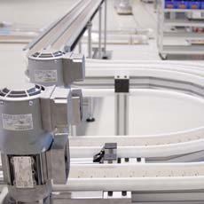
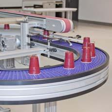
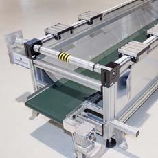
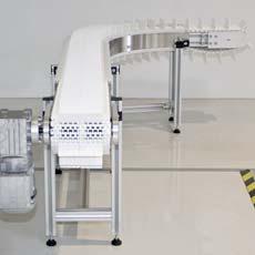
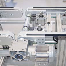
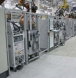
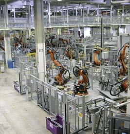
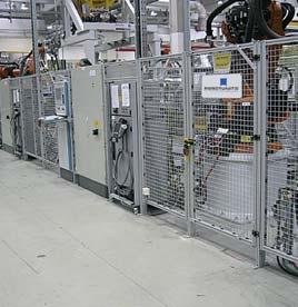
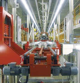
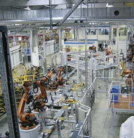
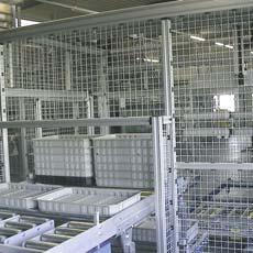
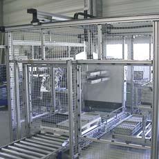
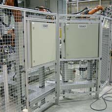
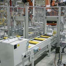
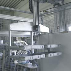
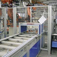
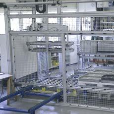
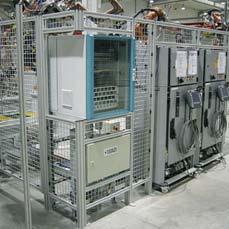
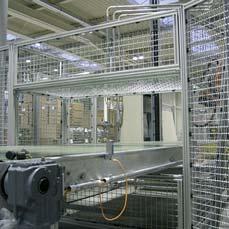
6 6 From a simple workbench to complex industrial production lines. The Robotunits Modular Automation System offers solutions that fascinate both engineers and assemblers.
7 7 Highlights of Robotunits Products Belt Conveyor System Page 8 Safety Fence System Page 10 Linear Motion System Page 12 Extrusion Technology Page 14 Fastening Technology Page 16 Accessories Page 18 Optimal Utilization of Resources Page 20

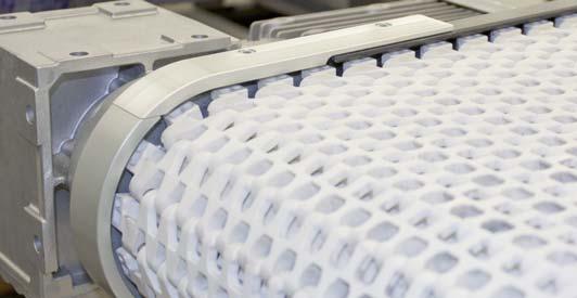
8 8 The Just-in-Time (JIT) Belt Conveyor System Success is often measured by efficiency and speed. For Robotunits customers this means always keeping one step ahead regarding the time required for delivery, design and assembly. An important contributor to this is the fact that the Belt Conveyor System is seamlessly integrated into the Modular Automation System. Advantages like these, as well as great product variety, maximum technical excellence and enormous potential to save time and money in design and assembly, are what makes Robotunits so unique. Special designs are available upon request.

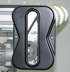
9 9 Impressive delivery times production time for your individual Belt Conveyor: 1 week Just-In-Time delivery Custom-made sizes select any standard frame width between 40 mm and 1200 mm select any conveyor length up to 6 m, longer units available upon request pre-assembled and height adjustable legs as an option fast adjustments to meet your individual requirements Flexibility in drive options and positions choose drive option and position of motor maintenance-free timing belt drive space saving direct drive Speed standard speed range from 2.6 m/min to 58 m/min higher speeds available upon request Speed Controller optional Idler options Roller diameters of 40 mm, 50 mm or 80 mm Nose bar (16 mm diameter) for transfer of small parts Wide variety of belts accumulation belt low & high friction belts high durability belts for abrasive and corrosive use Fully integrated conveyor system compatible with all our extrusion sizes uniformly continuous groove system free attachment groove on both lengthwise sides of the Belt Conveyor this makes it quick and easy to attach accessories or structural elements (such as stops) to the machine frame Save time, cut cost shortest lead time quick configuration of your custom conveyor every Belt Conveyor is already assembled and tested outstanding price/performance ratio Safety self-adjusting safety guard between the Belt Conveyor roll and the slider bed belt guard with viewing window for visual inspection complete documentation meeting the requirements of the Machinery Directive

10 10 Easily constructed Safety Fence System Safety standard requirements have never been as demanding as today. National and international standards have to be considered. Quickly changing production requirements and continuous upgrades and adaptations require a flexible and time-saving Safety Fence System. Order completely pre-assembled components that are easily and quickly installed. Nothing is so simple and safe as the Safety Fence System from Robotunits.

11 11 Turn-key offer Included in the price and delivery: ready-to-insert, complete assembled elements (including safety fence foot and connectors between elements) modular safety fence system with flat and door elements standard widths from 518 mm to 1507 mm or special-width elements standard height 2200 mm or special height elements Ready to install easy installation of fully assembled elements minimum installation time One Mesh Clip, many functions impact rated up to 80 kg at 10 km/h small number of parts visually appealing design High flexibility quick installation of all elements panels can be easily removed to gain access to machine area adjustable to any angle Easy installation only one person required for setup only one Allen wrench size needed reusable components Fully integrated Safety Fence System uniform slot size and shape completely compatible with entire Modular Automation System quick and easy attachment of accessories use of standard screws and standard elements Save time, cut cost no additional design expenses simple element selection efficient one-person installation simple adjustment and setup on-site just one order code for the complete safety fence element easy attachment of accessories (safety switches, etc.) Safety complete documentation meets European Machinery Safety Standards and the latest auto industry specifications

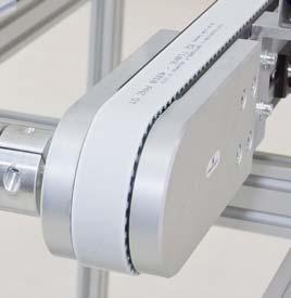
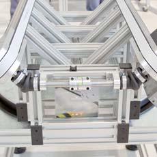
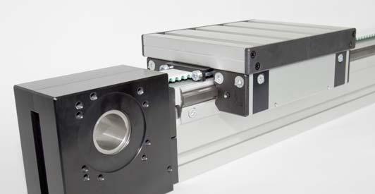
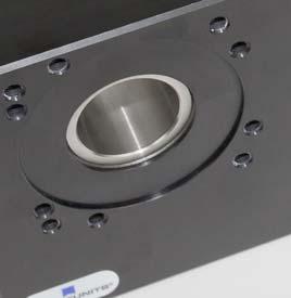
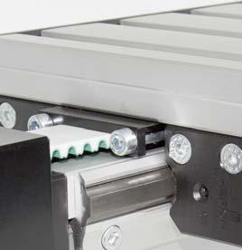
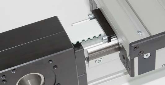
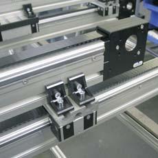
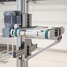
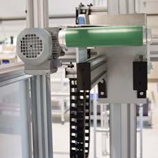
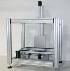
12 12 The Custom-Made Linear Motion System Customized linear motion technology. Based on our proven Extrusion and Fastening Technology, we have developed Linear Motion Units that meet the highest customer expectations in terms of versatility, stability and efficiency. Robotunits offers a Linear Motion System of the highest quality and precision, with a maximum potential for cost and time savings in design and assembly. Fully integrated Linear Motion System completely compatible with the entire Modular Automation System belt return inside the extrusion leaves 3 sides of the extrusion free for additional attachments available in 50 mm series It runs and runs and runs... single or double idlers can be used, depending on the load high strength due to special captive design of idler extrusion large rollers integrated fastening option for Flexible Energy Chain Guiderails instead of guide systems easily mounted guiderails eliminate the need for a separate guide system playfree datum edge positioning hardened, tempered steel guiderail allow heavier loads high wear resistance allows smooth and quiet operation quick and easy assembly Modular design of linear motion units customized linear motion units, from single units to complex 3 axis gantry systems single and multiple guiderails available in one system X-,Y-,Z-combinations possible almost limitless combinations

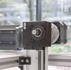
13 13 Drive options motor selection tailored to performance requirements minimal design time through expansion coupling system one size pulley for all chassis sizes Protection against damage integrated overrun protection prevents mechanical damage Save time, cut cost easy selection of components easy to order minimal design time required quick and easy attachment of accessories easy installation

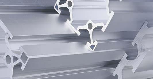
14 14 The Smart Extrusion Technology It all began with special purpose machine building. After many years of experience with the extrusions of various manufacturers we decided to develop our own Extrusion Technology. This was to form the basis of our own complete Modular Automation System. The result is maximum design and assembly possibilities with minimal time investment. Robotunits offers a system that will meet your highest expectations. The key element of the Modular Automation System is a unique Extrusion Technology, available in 40 mm and 50 mm size systems, which are fully compatible with each other and all other components. They utilize one slot size that allows new dimensions in design and assembly speed.
 allows for stronger")
15 15 Compatibility saves time a total of 12 shapes of 40 mm and 50 mm extrusion sizes simplify design and installation all extrusions are compatible with one another minimal training time minimal design time quick and easy assembly One slot size fits all uniform slot size allows compatibility of all extrusions the design of this extra large slot (14 mm wide, 14 mm deep) allows for stronger hardware and post assembly insertion of Drop-In-Nuts post insertion of heavy duty nuts up to M10 possible Tubular honeycomb structure the section modulus of a 50 mm by 50 mm extrusion is equivalent to the section modulus of a 50 mm by 50 mm steel tube with a 3 mm wall thickness the section modulus of the 50 mm by 50 mm extrusion is 30 % to 40 % higher than that of a 40 mm by 40 mm extrusion of comparable weight outstanding torsion and load resistance greater strength with less material means cost savings All you need to know is the extrusion length when you place an order, simply specify the desired length every extrusion is labeled prior to shipment (stock length, part number and position number, etc.) label information eliminates the measuring of extrusions prior to assembly Large slot depth guarantees maximum strength of connection maximum thread engagement for all screws up to M8 drop-in-nuts provides extra strength no need for bolt length adjustment thread depth is always greater than diameter of screw Precision is our standard integrated location groove guarantees precise and straight drilling 45 chamfered edges for easy attachment and visual continuity Vibration resistance through preloading concave surface of extrusion guarantees durable vibration resistance maximum wall thickness at key points prevents crimping no additional washers required for full contact Save time, cut cost easy to understand product range easy to order only length specifications are required for placing an order no detailed specifications needed for connectors labeled and tapped extrusions allow immediate assembly

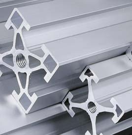
16 16 The Strong Fastening Technology A few years ago connecting without drilling, milling or welding was almost unthinkable. It is obvious that if you can eliminate machining or welding from the process you also lower your cost by preventing time-consuming adjustments and post processing of your designs. The Robotunits Fastening Technology is unique worldwide, not only because of its stability and rigidity, but also in its enormous potential for time savings from design to assembly. Every hole drilled is one hole too many all connections made without drilling or milling maximum wall thickness at key points prevents crimping no time needed for processing or alignment tasks unlimited reusability More space for your ideas 15-mm standard fastener height provides more space for additions quick and easy design no dimensioning of boreholes no part drawings required Maximum stability worldwide unique play-free, accurate and centrally aligned fastening technology single fastener provides up to 4.1 t (8,800lbs.) of tensile strength strength comparable to a welded connection maximum stability and strength for the entire production line One fastener, double value two-sided fastener provides equal strength on both sides of the connection twice the strength for the price of one no additional connectors needed completely assembled with standard length screws and a single Allen key

17 17 Stability increases with every rotation every turn positions centering inserts tighter into slot absolutely play-free, accurate and centrally aligned connection no loosening of bolts through vibration Inserting the drop-in nut simply insert the drop-in nut into the wide slot spring assembly protects drop-in-nut against unintended movement no time wasted aligning bolts; just slide to stop position quick and easy assembly Everything is possible even post assembly simple post-assembly integration of struts without dismantling the frame easy repositioning of struts at any time no cutting of existing structures no surface treatment required Save time, cut cost minimum assembly time required easy and quick selection of Fastening Technology no measuring of boreholes no dimensioning of boreholes length of the extrusion is the only measurement needed for the design two-sided connection with one fastener


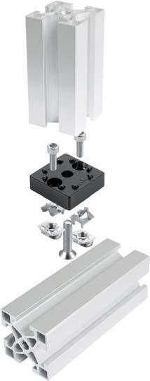
18 18 Multifunctional Accessories Every small detail has a big impact on the entire system, especially when countless accessories fill hundreds of catalog pages. Developing an accessory for every new application fundamentally contradicts our concept of a World-Class product range. Our accessories are multifunctional and fit not only to an exactly defined component, but to all other components in the entire Modular Automation System.


19 19 Cover or fasten universally usable Cover or Insert Extrusion fits 40 mm and 50 mm extrusions suitable for mounting 4 mm to 6 mm thick panels covers T-slots and protects against dust and water spray suitable for cable routing easy to assemble: snap in and go Everything is possible with a single hinge universal hinge fits all applications one hinge for all doors attachment of non-robotunits components possible Fine-tuning and fastening element multifunctional Fine-Tuning and Fastening Element form-located positioning infinitely adjustable post-assembly insertion possible Unique clamping device allows easy attachment of parts facilitates mounting of 3 mm-10 mm thick panels without drilling clamping device is quickly mounted by inserting it into the slot no drilling of panels required parts can be reused fits 40 mm and 50 mm extrusions Safety interlocks: quick and secure installation quick and safe installation without the need for additional parts fits 40 mm and 50 mm extrusions easy to install and adjust no drilling or preparing of extrusions needed IP65 protection class in accordance with TEC 529 Save time, cut cost multifunctional accessories reduces your cost of ordering and your inventory overhead standard labeling saves even more time in assembly and storage

20 20 Optimal utilization of resources In or Out Flexibility and continuity are prerequisites for your success. More and more, companies must react quickly to changing production workloads or product cycle times. New systems are often required that can easily be adjusted to these changing demands. Robotunits supports its customers changing needs with a comprehensive Outsourcing Program.
21 21 Turnover Increase in your turnover rate through the flexible Internal Service and Outsourcing Program from Robotunits. Fluctuating turnover rates Capacity constraints in design and/or assembly jobs Average turnover rate Downtime in design and/or assembly jobs Time Capacity constraints in assembly we support or take over project design utilizing the Robotunits Modular Automation System we support you in allocating design capacity for your projects Downtimes in design information exchange about possible design projects or customer needs respectively we arrange projects for our customers if possible Capacity constraints in assembly Robotunits assembly specialists take over assembly or partial assembly within the Robotunits Modular Automation System, even on-site in exceptional cases complete assembly of your design by our assembly team in our facility Downtimes in assembly we deliver only the components, the assembly is carried out by your personnel
22 22 Our Key to Your Success: Quick and Simple Simplicity at all levels is the basis for high speed. Advance through Innovation We strive to support you with our innovative products to stay one step ahead of the competition. More with Less Our mushroom strategy is based on multifunctional components used throughout the system. For you this means less inventory, less training expense and more time savings.
23 The Modular Automation System Belt Conveyor System Belt Conveyors Modular Belt Conveyors Timing Belt Conveyors Safety Fence System Page 25 Page 53 Basic System Allround System Linear Motion System Linear Motion Unit 50 Linear Motion Unit 100 Page 73 Extrusion Technology 40 mm Series 50 mm Series Page 81 FasteningTechnology 40 mm Series 50 mm Series Page 91 Accessories Belt Conveyor Accessories Safety Fence Accessories Linear Motion Accessories General Modular Accessories Page 108

24 24
25 25 The Just-In-Time Belt Conveyor System Belt Conveyors Page 26 C4N Belt Conveyors Page 28 C5N Belt Conveyors Page 30 C8N Belt Conveyors Page 32 C4F Conveyor Stand Page 34 C8F Conveyor Stand Page 35 Modular Belt Conveyors Page 36 C8M Modular Belt Conveyors Page 38 C8M Modular Belt Conveyors Curved Page 40 C8F Conveyor Stand Page 35 Timing Belt Conveyors Page 42 C4T Timing Belt Conveyors Page 44 C8T Timing Belt Conveyors Page 46 C4G Conveyor Stand Page 48 C8G Conveyor Stand Page 49 Conveyor Request Form Page 51 Belt Conveyor Accessory Overview Page 108

 ➋")
")

 C5N Belt")

 ➋ belt")
26 26 C4N Belt Conveyor Drive Options ➊ ➋ ➍ ➌ ➊ Front end direct drive (page 28) ➋ Front end timing belt drive (page 28) ➌ Center drive with timing belt (page 28) ➍ Nose bar (page 28) C5N Belt Conveyor Drive Options ➊ ➋ ➊ Front end direct drive (page 30) ➋ Front end timing belt drive (page 30)


27 27 C8N Belt Conveyor Drive Options ➊ ➋ ➊ Direct drive with torque arm (page 32) ➋ Front end timing belt drive (page 32)
28 28 C4N Belt Conveyor Automated assembly, general packaging, plastic & injection molding, transfer of small parts, vacuum capabilities, CE models available A B 40 Belt speed for timing belt drive from 2.6 m/min to 55 m/min (50Hz) from 3.2 m/min to 58 m/min (60Hz) Belt speed for direct drive from 2.6 m/min to 30 m/min (50Hz) from 3.2 m/min to 33 m/min (60Hz) frame width C4N with side guides frame width 120mm: belt width = frame width - 15mm frame width > 120mm: belt width = frame width - 20mm C4N without side guides belt width = frame width - 10mm 11 Drive power depending on belt speed ranging from 0.12 kw to 0.37 kw ( /400V; 50/60Hz; IP55) Max. total load of material to be conveyed Fmax. 300 N N A B Belt Features low friction, high friction, accumulation, food grade, cut & oil resistant, cleated for incline transport, integrated belt side guides, etc. Higher belt speed upon request! Drive Options 1 Front end timing belt drive Front end direct drive Center drive with timing belt 2 A E K Front end timing belt drive, left Front end timing belt drive, right Front end timing belt drive, left, tail end nose bar Front end timing belt drive, right, tail end nose bar Front end direct drive left B F L Front end direct drive, right C G N Front end direct drive, left, with tail end nose bar D H Q Front end direct drive, right, with tail end nose bar Center drive with timing belt Center drive with timing belt and tail end nose bar Center drive with timing belt and tail end nose bar Center drive with timing belt and nose bar on both ends Front End Timing Belt Drive Optional: nose bar 154 R8 60 max. 140 belt width frame width max. 280 min length max. Ø B = X x 40 X = 1 to max. 10 max. 320 max. 390 (with forced cooling fan)
29 29 Front End Direct Drive Optional: nose bar 154 R8 30 belt width frame width max. 220 max max. Ø140 length B = X x 40 X = 1 to max. 10 max. 310 max. 380 (with forced cooling fan) Center Drive With Timing Belt Optional: nose bar 154 R max length 150 belt width max. Ø140 frame width max B = X x 40 X = 1 to max. 10 max. 450 max. 520 (with forced cooling fan) Standard Widths And Lengths Description Frame Width F max. 3 Belt Conveyor mm 300 N Belt Conveyor mm 700 N Belt Conveyor mm 1100 N Belt Conveyor mm 1500 N Belt Conveyor mm 1900 N Belt Conveyor mm 2300 N Belt Conveyor mm 2400 N Belt Conveyor mm 2400 N Standard lengths Keep in mind the minimum length to width ratio of 1.5:1 for lengths up to mm Special widths and special lengths are available upon request. Speed controller information (page 110) Order Placement To place an order please use the Conveyor Request Form (page 51) or visit the online Belt Conveyor configuration tool at 1) Standard running direction is pulling 2) Simply reverse the polarity to change the running direction of any center drive 3) Approximate value: F max may vary depending on the application Diagram dimensions in mm
30 30 C5N Belt Conveyor Automated assembly, general packaging, plastic & injection molding, transfer of small parts, vacuum capabilities, CE models available A B 50 Belt speed for timing belt drive from 3.2 m/min to 66 m/min (50Hz) from 3.8 m/min to 71 m/min (60Hz) Belt speed for direct drive from 3 m/min to 37 m/min (50Hz) from 3.8 m/min to 40 m/min (60Hz) frame width C5N with side guides belt width = frame width - 20mm C5N without side guides belt width = frame width - 12mm 16 Drive power depending on belt speed ranging from 0.12 kw to 0.37 kw ( /400V; 50/60Hz; IP55) Max. total load of material to be conveyed Fmax N N A B Belt Features low friction, high friction, accumulation, food grade, cut & oil resistant, cleated for incline transport, integrated belt side guides, etc. Higher belt speed upon request! Drive Options 1 Front end timing belt drive Front end direct drive A Front end timing belt drive, left E Front end direct drive left B Front end timing belt drive, right F Front end direct drive, right Front End Timing Belt Drive 65 max. 140 belt width frame width 95 length 60 max. 290 min max. 320 max. 390 (with forced cooling fan) max. Ø140
31 31 Front End Direct Drive max. 220 belt width max. Ø140 frame width length max max. 310 max. 380 (with forced cooling fan) Standard Widths And Lengths Description Frame Width F max. 2 Belt Conveyor mm 3000 N Belt Conveyor mm 3400 N Belt Conveyor mm 3000 N Standard lengths Keep in mind the minimum length to width ratio of 1.5:1 for lengths up to mm Special widths and special lengths are available upon request. Speed controller information (page 110) Order Placement To place an order please use the Conveyor Request Form (page 51) or visit the online Belt Conveyor configuration tool at 1) Standard running direction is pulling 2) Approximate value: F max may vary depending on the application Diagram dimensions in mm
32 32 C8N Belt Conveyor Automated assembly, general packaging, plastic & injection molding, transfer of small parts, vacuum capabilities, CE models available Belt speed for timing belt drive from 5 m/min to 67 m/min (50 Hz) from 4.9 m/min to 72 m/min (60 Hz) Belt speed for direct drive from 4.7 m/min to 56 m/min (50 Hz) from 5.7 m/min to 61 m/min (60 Hz) A frame width C8N with side guides belt width = frame width - 20mm C8N without side guides belt width = frame width - 12mm B Drive power depending on belt speed ranging from 0.25 kw to 0.55 kw ( /400V; 50/60Hz; IP55) Max. total load of material to be conveyed Fmax N N A B Belt Features low friction, high friction, accumulation, food grade, cut & oil resistant, cleated for incline transport, integrated belt side guides, etc. Higher belt speed upon request! Drive Options 1 Front end timing belt drive Direct drive with torque arm A Front end timing belt drive, left I Direct drive with torque arm, left B Front end timing belt drive, right J Direct drive with torque arm, right Front End Timing Belt Drive 70 max. 160 belt width frame width 165 length max. 340 min. 25 max. 400 max. 470 max. Ø (with forced cooling fan)
33 33 Direct Drive With Torque Arm belt width max. 230 max frame width max. Ø140 length max. 360 max. 430 (with forced cooling fan) Standard Widths And Lengths Description Frame Width F max. 2 Belt Conveyor mm 6000 N Belt Conveyor mm 7000 N Belt Conveyor mm 8000 N Belt Conveyor mm 5000 N Belt Conveyor mm 3600 N Standard lengths Keep in mind the minimum length to width ratio of 1.5:1 for lengths up to mm Special widths and special lengths are available upon request. Speed controller information (page 110) Design Options 3 Incline Conveyors (side view) Order Placement To place an order please use the Conveyor Request Form (page 51) or visit the online Belt Conveyor configuration tool at 1) Standard running direction is pulling 2) Approximate value: F max may vary depending on the application 3) Please contact our team for more details on Incline Conveyors Diagram dimensions in mm
34 34 C4F Conveyor Stand Stand for C4N and C5N Belt Conveyors and gravity roller conveyors Support distance Material: EN AW-6063-T66 clear anodized aluminum; galvanized GD-Zn; galvanized steel; PA 6 composite or rubber height Scope of Delivery Conveyor stand, completely assembled, In addition, as per order code: Drop-in Nuts TIN 4508 Screws IBS M08x020 NIKO Washers BLS M max over 1800 with additional vertical support length Standard Conveyor Stands S I R 40 frame width max. 600 height Leveling bases BAS 4008 Height adjustment ± 15 mm Safety Fence Floor Bracket for anchoring BAP 2051 Height adjustment, mm Swivel Castors with brakes CAS Wide Conveyor Stands H J G min. 100 frame width max. 600 height Wide conveyor stand offers additional stability when conveyor heights exceed 3 times the frame width Leveling Bases BAS 4008 Height adjustment ±15 mm Safety Fence Floor Bracket for anchoring BAP 2051 Height adjustment, mm Swivel Castors with brakes CAS 3080 width Description Frame Width Type Length Height Conveyor Stand C4F _ NN 1) Please complete the order code by adding the corresponding letter for order processing Diagram dimensions in mm
35 35 C8F Conveyor Stand Stand for C8N Belt Conveyors and gravity roller conveyors Support distance Material: EN AW-6063-T66 clear anodized aluminum; galvanized GD-Zn; galvanized steel; PA 6 composite or rubber Scope of Delivery Conveyor stand, completely assembled, In addition, as per order code: Drop-in Nuts TIN 4508 Screws IBS M08x020 NIKO Washers BLS M008 height max over 1800 with additional vertical support length Standard Conveyor Stands S I R 40 frame width height Leveling Bases BAS 1020 Height adjustment ±30 mm Safety Fence Floor Bracket for anchoring BAP 2051 Height adjustment, mm Swivel Castors with brakes CAS Description Frame Width Type Length Height Conveyor Stand C8F _ NN 1) Please complete the order code by adding the corresponding letter for order processing Diagram dimensions in mm


")

36 36 C8M Modular Belt Conveyor Drive Options ➊ ➋ ➊ Direct drive with torque arm (page 38) ➋ Front end timing belt drive (page 38)


37 37 C8M Modular Belt Conveyor Curved Drive Options ➊ ➋ ➊ Direct drive with torque arm (page 40) ➋ Front end timing belt drive (page 40)
38 38 C8M Modular Belt Conveyor Automated assembly, general packaging, plastic & injection molding, transportation of heavy, sharp parts, accumulation, CE models available 10 1 Belt speeds range (timing belt drive) from 5.5 m/min to 61 m/min (50 and 60 Hz) Belt speeds range (direct drive) from 6.5 m/min to 69 m/min (50 and 60 Hz) 121 Drive power depending on belt speed ranging from 0.25 kw to 0.55 kw (230/400V; 50/60Hz; IP55) Modular belt increments 1 inch modular belt width = frame width - 15mm frame width 10 Modular Belt Features Modular belt open Modular belt closed Maximum load to be conveyed: 8000 N Drive Options 1 Front end timing belt drive Direct drive with torque arm A Front end timing belt drive, left I Direct drive with torque arm, left B Front end timing belt drive, right length max max max. Ø 140 min. 5 max. 350 frame width modular belt width 65 max. 175 J Direct drive with torque arm, right Front End Timing Belt Drive 215 max. 400 max. 470 (with forced cooling fan)
39 39 Direct Drive With Torque Arm length max. Ø 140 max. 190 frame width modular belt width max max max max. 360 max. 430 (with forced cooling fan) Design Options 2 Incline Conveyors (side view) Length And Frame Width Description Min. length Max. length Frame width min. 3 Frame width max. 3 C8M Modular Belt Conveyor Front end timing belt drive 1000 mm mm 65 mm 2015 mm C8M Modular Belt Conveyor Direct drive with torque arm 1000 mm mm 65 mm 2015 mm Order Placement To place an order please use the Conveyor Request Form (page 51) or visit the online Belt Conveyor configuration tool at 1) Standard direction is pulling 2) Please contact our team for more details on Incline Conveyors 3) Frame widths can be ordered ranging from min. 65 mm to max mm in increments of 50 mm. Diagram dimensions in mm
40 40 C8M Modular Belt Conveyor Curved Automated assembly, general packaging, plastic & injection molding, transportation of heavy, sharp parts, accumulation, CE models available 9.8 or 11.5 Belt speeds range (timing belt drive) from 5.5 m/min to 61 m/min (50 and 60 Hz) Belt speeds range (direct drive) from 6.5 m/min to 69 m/min (50 and 60 Hz) 11 or Drive power depending on belt speed ranging from 0.25 kw to 0.55 kw (230/400V; 50/60Hz; IP55) Modular belt increments 1 inch Modular Belt Features Modular belt open modular belt width = frame width - 15mm frame width Maximum load: depends on application, please contact sales! Drive Options 1 Front end timing belt drive Direct drive with torque arm A Front end timing belt drive left I Direct drive with torque arm, left B Front end timing belt drive, right J Direct drive with torque arm, right Front End Timing Belt Drive in-feed length curve radius max. Ø max. 175 curve angle out-feed length max min. 5 max. 365 modular belt width frame width max. 400 max. 470 (with forced cooling fan)
41 41 Direct Drive With Torque Arm in-feed length out-feed length max. 190 curve radius max. Ø 140 max. 360 max. 430 (with forced cooling fan) curve angle max max. 235 modular belt width frame width Design Options 2 Design Options (top view) Incline Conveyors (side view) Frame Width Description Frame width min. 3 Frame width max. 3 C8M Modular Belt Conveyor Curved Front end timing belt drive 215 mm 1215 mm C8M Modular Belt Conveyor Curved Front end direct drive with torque arm 215 mm 1215 mm Order Placement To place an order please use the Conveyor Request Form (page 51) or visit the online Belt Conveyor configuration tool at 1) Standard direction is pulling 2) Please contact our team for more details on Incline Conveyors 3) Frame widths can be ordered ranging from min. 215 mm to max mm in increments of 50 mm. Diagram dimensions in mm
 ➋ Connection shaft with")
 ➍ Timing belt lane without motor, with output shaft, right")
42 42 C4T Timing Belt Conveyor Drive And Connection Options ➍ ➋ ➌ ➋ ➊ ➊ Front end timing belt drive, right, with output shaft (page 44) ➋ Connection shaft with coupling COL 5220 (page 143) ➌ Timing belt lane without motor, output shaft, right (page 44) ➍ Timing belt lane without motor, with output shaft, right (page 44)

 ➌")

 ➏ Connection hub")
 ➑ Timing belt lane without motor, with splined")
43 43 C8T Timing Belt Conveyor Drive And Connection Options ➌ ➎ ➍ ➌ ➑ ➋ ➐ ➊ ➏ ➊ Direct drive with torque arm and output shaft (page 46) ➋ Front end timing belt drive, right, with output shaft (page 46) ➌ Connection shaft with coupling COL 5240 (page 143) ➍ Timing belt lane without motor, with output shaft, right (page 46) ➎ Timing belt lane without motor, output shaft on both sides (page 46) ➏ Connection hub COP 4501 (page 111) ➐ Splined shaft COL 8500 (page 111) ➑ Timing belt lane without motor, with splined shaft hub (page 46)
44 44 C4T Timing Belt Conveyor Used for a wide variety of conveying applications speed range for timing belt drive from 2.75 m/min to 56 m/min (50 Hz) from 3.2 m/min to 59 m/min (60 Hz) F max belt width 32 mm Drive power depending on belt speed ranging from 0.12 kw to 0.37 kw (230/400V; 50/60Hz; IP55) Max. total load of material to be conveyed Fmax N Standard lengths ranging from 400 to mm Number of teeth per pulley = 30 Pitch circle diameter = mm Belt Features Standard application, cleated for incline transport, accumulation, etc. Higher belt speed upon request! Drive Options 1 Front end timing belt drive, Fmax 1600 N Timing belt lane without motor Front end timing belt drive, double lane A Front end timing belt drive, left T Timing belt lane with output shaft on both sides O 2 Front end timing belt drive, left, double lane B Front end timing belt drive, right U Timing belt lane with output shaft, left P 2 Front end timing belt drive, right, double lane O Front end timing belt drive, left and output shaft V Timing belt lane with output shaft, right Front end timing belt drive, triple lane P Front end timing belt drive, right and output shaft O 3 Front end timing belt drive, left, triple lane P 3 Front end timing belt drive, right, triple lane length 50 max. 280 min. 15 Front End Timing Belt Drive max. Ø max. 320 max. 390 (with forced cooling fan)
45 45 Front End Timing Belt Drive O/P max. 140 max. 100 belt width 32 mm frame width 40 mm belt width 32 mm frame width 40mm center-to-center dist. MA C4T 60 max. 140 max. 100 center-to-center dist. MA C4T (130.5) Ø Front End Timing Belt Drive, Double Lane U/V 60 max. 140 max. 100 belt width 32 mm frame width 40mm center-to-center dist. MA C4T (81) Ø Front End Timing Belt Drive, Triple Lane T (105) Ø Description Timing Belt Drive Length v = m/min. Timing Belt Conveyor 40 Front end timing belt drive C4T 0040 N,_ Timing Belt Conveyor 40 Front end timing belt drive, double lane C4T ,_ Timing Belt Conveyor 40 Front end timing belt drive, triple lane C4T ,_ Timing Belt Conveyor 40 Timing belt lane without motor C4T 0040 N 1) Standard direction is pulling 2) Please complete the order code by adding the corresponding letter for order processing Diagram dimensions in mm
46 46 C8T Timing Belt Conveyor Used for a wide variety of conveying applications F max belt width 32mm speed ranges for timing belt drive from 6 m/min to 63 m/min (50 Hz) from 5.7 m/min to 71 m/min (60 Hz) speed ranges for direct drive from 6 m/min to 63 m/min (50 Hz) from 6.7 m/min to 71 m/min (60 Hz) Drive power depending on belt speed ranging from 0.25 kw to 0.37 kw (230/400V; 50/60Hz; IP55) Standard lengths ranging from 550 to mm Teeth on each pulley = 32 Pitch circle diameter = mm Front end drive, double lane Max. total load of material to be conveyed Fmax N or 6000 N, depending on type of drive Drive Options 1 Front end timing belt drive, Fmax 4000 N A Front end timing belt drive, left Belt Features Standard application, cleated for incline transport, accumulation, etc. Front end direct drive, Fmax 6000 N E Front end direct drive left O 2 P 2 R 2 S 2 Front end timing belt drive, left, double lane Front end timing belt drive, right, double lane Front end direct drive, left, double lane Front end direct drive, right, double lane B O P Front end timing belt drive, right Front end timing belt drive, left and output shaft Front end timing belt drive, right and output shaft Front End Timing Belt Drive length F R S Front end direct drive, right Front end direct drive, left and output shaft Front end direct drive, right and output shaft Front end drive, triple lane O P R S Front end timing belt drive, left, triple lane Front end timing belt drive, right, triple lane Front end direct drive left, triple lane Front end direct drive right, triple lane 104 max. 350 min max. 400 max. 470 (with forced cooling fan) max. Ø 140 Front End Direct Drive length Timing belt lane without motor T U V Timing belt lane with output shaft on both sides Timing belt lane with output shaft, left Timing belt lane with output shaft, right max. 230 max. 360 max. 430 (with forced cooling fan) Timing belt lane without motor, adjustable W Timing belt lane with splined shaft hub
47 47 Front End Timing Belt Drive, Double Lane max max. 120 belt width 32 mm frame width 40 mm O/P (164.5) Ø max. 160 max Front End Direct Lane, Double Lane belt width 32 mm frame width 40 mm center-to-center dist. MA C8T center-to-center dist. MA C8T U/V (115.5) T (156) Ø 20 Ø max. 190 max. 190 max. Ø140 max. Ø140 belt width 32 mm frame width 40 mm belt width 32 mm frame width 40 mm center-to-center dist. MA C8T center-to-center dist. MA C8T (max. 290) 75 R/S max Ø 20 W, adjustable Splined shaft hub DIN ISO 14-6x16x20 2 Description Timing Belt Drive Length v = m/min. Timing Belt Conveyor 80 Front end timing belt drive C8T 0040 N,_ Timing Belt Conveyor 80 Front end timing belt drive, double lane C8T ,_ Timing Belt Conveyor 80 Front end timing belt drive, triple lane C8T ,_ Timing Belt Conveyor 80 Front end direct drive C8T 0040 N,_ Timing Belt Conveyor 80 Front end direct drive, double lane C8T ,_ Timing Belt Conveyor 80 Front end direct drive C8T ,_ Timing Belt Conveyor 80 Timing belt lane without motor C8T 0040 N 1) Standard direction is pulling 2) Please complete the order code by adding the corresponding letter for order processing Diagram dimensions in mm
48 48 C4G Conveyor Stand Stand for C4T Support distance Material: EN AW-6063-T66 clear anodized aluminum; galvanized GD-Zn; galvanized steel; PA 6 composite or rubber height Scope of Delivery Conveyor stand, completely assembled, In addition, as per order code: Drop-in Nuts TIN 4508 Screws IBS M08x020 NIKO Washers BLS M008 length max over 1800 with additional vertical support Stand Types: Single Lane S Leveling Bases BAS 4008 Height adjustment ±15 mm I Safety Fence Floor Brackets for anchoring BAP 2051 Height adjustment, mm R Swivel Castors with brakes CAS 3080 height height/2 200 width = height/3 Stand Types: Double Lanes H Leveling Bases BAS 4008 Height adjustment ±15 mm J Safety Fence Floor Brackets for anchoring BAP 2051 Height adjustment, mm G Swivel Castors with brakes CAS 3080 height height/2 200 width = height/3 Stand Types: Triple Lane K Leveling Bases BAS 4008 Height adjustment ±15 mm L Safety Fence Floor Brackets for anchoring BAP 2051 Height adjustment, mm M Swivel Castors with brakes CAS 3080 height height/2 200 width = height/2 1 Description Width Type Length Height Conveyor Stand C4G _ NN 1) Please complete the order code by adding the corresponding letter for order processing Diagram dimensions in mm
49 49 C8G Conveyor Stand Stand for C8T Support distance Material: EN AW-6063-T66 clear anodized aluminum; galvanized GD-Zn; galvanized steel; PA 6 composite or rubber height Scope of Delivery Conveyor stand, completely assembled, In addition, as per order code: Drop-in Nuts TIN 4508 Screws IBS M08x020 NIKO Washers BLS M008 length max over 1800 with additional vertical support Stand Types: Single Lane S Leveling Bases BAS 1020 Height adjustment ±30 mm I Safety Fence Floor Brackets for anchoring BAP 2051 Height adjustment, mm R Swivel Castors with brakes CAS 3080 height height/2 200 width = height/3 Stand Types: Double Lanes Leveling Bases BAS 1020 Height adjustment ±30 mm H J G Safety Fence Floor Brackets for anchoring BAP 2051 Height adjustment, mm Swivel Castors with brakes CAS 3080 height height/2 200 width = height/3 Stand Types: Triple Lane Leveling Bases BAS 1020 Height adjustment ±30 mm K L M Safety Fence Floor Brackets for anchoring BAP 2051 Height adjustment, mm Swivel Castors with brakes CAS 3080 height height/2 200 width = height/2 1 Description Width Type Length Height Conveyor Stand C8G _ NN 1) Please complete the order code by adding the corresponding letter for order processing Diagram dimensions in mm


50 50 Belt Conveyor Examples
51 51 Conveyor Request Form Company: Contact Person: Date: Telephone: Fax: L A layout diagram is required for curved conveyors. Number:... units Width:... mm Length:... mm B Drive options: See Catalog Pages 28 to 46 (enter letter)... Side Guides: H H =... mm Belt Speed: V =... m/min Variable speed: Yes No... to... m/min Frequency converter: Yes No Power Supply: Standard /400V, 50/60 Hz Yes No Power Supply: Special Voltage Required Yes No... V,... Hz Normal operation Accumulation Cycle mode Installation orientation: horizontal Special belt requirements: Installation orientation: inclined... Weight per unit:... kg Installation orientation: downhill... Temperature of parts:... C Parts to be Conveyed (Layout Sketch): Total belt load:... kg Part material:... Motor Orientation: 270 Location of terminal box: Base Frame: X Max. Approved Belt sag: H =... mm X X =... mm

52 52
53 53 Easily constructed Safety Fence System Basic System Page 54 Basic Panel Page 56 Basic Single Door Page 58 Basic Double Door Page 59 Basic Sliding Door Page 60 Allround System Page 62 Allround Panel Page 64 Allround Post Page 66 Allround Single Door Page 67 Allround Double Door Page 68 Allround Sliding Door Page 69 Safety Distances for Safety Systems Page 71 Safety Fence Accessory Overview Page 108


54 54 Basic System The Basic system is the classic among Robotunits safety fence systems. Easy to use and low in price. Ideal for standard applications in machine design and in production automation. The Basic system with Weld Mesh is capable of stopping up to 80 kg at 10 km/h. How does the Basic system work? With the Basic system, the Basic panels (B) are lined up and then directly connected with one another using safety fence fasteners. B B B Basic System Overview Panel Options Overview Weld mesh with weld mesh clip Polycarbonate with Panel Profile Basic Panel Panel Basic Doors Single Door Double Door Sliding Door
55 55 Basic System Dimensions B B B D D door gap panel height 2200 ground clearance 179 inside height 2160 inside width 1044 B B B 40 B B B B D
56 56 SBE Basic Panel Standard Width For general safety fencing Material: EN AW-6063-T66 clear anodized aluminum; galvanized steel, powder-coated, chrome silver steel; black ABS V0 composite; Weld Mesh or polycarbonate; conductive Weld Mesh and frame; Safety Fence Floor Bracket height adjustable from 10 to 40 mm Scope of Delivery Completely pre-assembled, consisting of: 2 Post Extrusions 40 x 40 PIL Horizontal Extrusions 40 x 40 PIL Fasteners FAS Safety Fence Fastener TIN End Caps CAP Safety Fence Floor Brackets BAP 2051 Panel option as per order code: Weld mesh with Weld Mesh Clip and safety fence mesh retainer Polycarbonate with panel profile 40 ground clearance 179 panel height 2200 Panel option: Weld Mesh or 4-mm thick polycarbonate Design tip: Standard widths offer an outstanding price/performance ratio and quick delivery panel width 40 Description Panel Width Panel Option Weight Basic Panel Standard Width 0518 Weld Mesh SBE 0518 SNA kg Basic Panel Standard Width 0776 Weld Mesh SBE 0776 SNA kg Basic Panel Standard Width 1034 Weld Mesh SBE 1034 SNA kg Basic Panel Standard Width 1507 Weld Mesh SBE 1507 SNA kg Basic Panel Standard Width 0518 Polycarbonate SBE 0518 PNA kg Basic Panel Standard Width 0776 Polycarbonate SBE 0776 PNA kg Basic Panel Standard Width 1034 Polycarbonate SBE 1034 PNA kg Basic Panel Standard Width 1507 Polycarbonate SBE 1507 PNA kg Diagram dimensions in mm
57 57 SBE Basic Panel Special Width For general safety fencing Material: EN AW-6063-T66 clear anodized aluminum; galvanized steel, powder-coated, chrome silver steel; black ABS V0 composite; Weld Mesh or polycarbonate; conductive Weld Mesh and frame; Safety Fence Floor Bracket height adjustable from 10 to 40 mm Scope of Delivery Completely pre-assembled, consisting of: 2 Post Extrusions 40 x 40 PIL Horizontal Extrusions 40 x 40 PIL Fasteners FAS Safety Fence Fastener TIN End Caps CAP Safety Fence Floor Brackets BAP 2051 Panel option as per order code: Weld mesh with Weld Mesh Clip and safety fence mesh retainer Polycarbonate with panel profile 40 ground clearance 179 panel height 2200 Panel option: Weld Mesh or 4-mm thick polycarbonate Note on polycarbonate: Any special widths from 152 mm to 1506 mm are available panel width 40 Description Panel Width Panel Option Weight Basic Panel Special Width 0131 Weld Mesh SBE 0131 SNA kg Basic Panel Special Width 0174 Weld Mesh SBE 0174 SNA kg Basic Panel Special Width 0217 Weld Mesh SBE 0217 SNA kg Basic Panel Special Width 0260 Weld Mesh SBE 0260 SNA kg Basic Panel Special Width 0303 Weld Mesh SBE 0303 SNA kg Basic Panel Special Width 0346 Weld Mesh SBE 0346 SNA kg Basic Panel Special Width 0389 Weld Mesh SBE 0389 SNA kg Basic Panel Special Width 0432 Weld Mesh SBE 0432 SNA kg Basic Panel Special Width 0475 Weld Mesh SBE 0475 SNA kg Basic Panel Special Width 0561 Weld Mesh SBE 0561 SNA kg Basic Panel Special Width 0604 Weld Mesh SBE 0604 SNA kg Basic Panel Special Width 0647 Weld Mesh SBE 0647 SNA kg Basic Panel Special Width 0690 Weld Mesh SBE 0690 SNA kg Basic Panel Special Width 0733 Weld Mesh SBE 0733 SNA kg Basic Panel Special Width 0819 Weld Mesh SBE 0819 SNA kg Basic Panel Special Width 0862 Weld Mesh SBE 0862 SNA kg Basic Panel Special Width 0905 Weld Mesh SBE 0905 SNA kg Basic Panel Special Width 0948 Weld Mesh SBE 0948 SNA kg Basic Panel Special Width 0991 Weld Mesh SBE 0991 SNA kg Basic Panel Special Width 1077 Weld Mesh SBE 1077 SNA kg Basic Panel Special Width 1120 Weld Mesh SBE 1120 SNA kg Basic Panel Special Width 1163 Weld Mesh SBE 1163 SNA kg Basic Panel Special Width 1206 Weld Mesh SBE 1206 SNA kg Basic Panel Special Width 1249 Weld Mesh SBE 1249 SNA kg Basic Panel Special Width 1292 Weld Mesh SBE 1292 SNA kg Basic Panel Special Width 1335 Weld Mesh SBE 1335 SNA kg Basic Panel Special Width 1378 Weld Mesh SBE 1378 SNA kg Basic Panel Special Width 1421 Weld Mesh SBE 1421 SNA kg Basic Panel Special Width 1464 Weld Mesh SBE 1464 SNA kg
58 58 SBS 1044 Basic Single Door For general safety fencing Material: EN AW-6063-T66 clear anodized aluminum; galvanized steel, powder-coated, chrome silver steel; black ABS V0 composite; Weld Mesh or polycarbonate; conductive Weld Mesh and frame; Safety Fence Floor Bracket height adjustable from 10 to 40 mm Scope of Delivery Completely pre-assembled, consisting of: 2 Post Extrusions 40 x 80 PIL Horizontal Extrusion 40 x 40 PIL Door Panel Extrusions 40 x 40 PIL Fasteners FAS Safety Fence Fastener TIN End Caps CAP End Caps CAP Safety Fence Floor Brackets BAP Handle DOR Hinges DOR Door Catch DOR Door Stop DOR 4555 Panel option as per order code: Weld mesh with Weld Mesh Clip and safety fence mesh retainer Polycarbonate with panel profile inside height ground clearance 179 inside width 1044 single-door width 1124 single-door height Left-hand hung Single Door Description Hinge position Panel Option Weight Basic Single Door Left Weld Mesh SBS 1044 SLA kg Basic Single Door Right Weld Mesh SBS 1044 SRA kg Basic Single Door Left Polycarbonate SBS 1044 PLA kg Basic Single Door Right Polycarbonate SBS 1044 PRA kg Diagram dimensions in mm

59 59 SBD 2083 Basic Double Door For general safety fencing Material: EN AW-6063-T66 clear anodized aluminum; galvanized steel, powder-coated, chrome silver steel; black ABS V0 composite; Weld Mesh or polycarbonate; conductive Weld Mesh and frame; Safety Fence Floor Bracket height adjustable from 10 to 40 mm inside height 2160 double-door height 2200 Left-hand hung Double Door Scope of Delivery Completely pre-assembled, consisting of: 2 Post Extrusions 40 x 80 PIL Horizontal Extrusion 40 x 40 PIL Door Panel Extrusions 40 x 40 PIL Fasteners FAS Safety Fence Fastener TIN End Caps CAP End Caps CAP Safety Fence Floor Brackets BAP Handle DOR Hinges DOR Door Catch DOR Door Stop DOR Floor Catch DOR 4561 Panel option as per order code: Weld mesh with Weld Mesh Clip and safety fence mesh retainer Polycarbonate with panel profile ground clearance 179 inside width 2083 double-door width Ø Description Hinge position Panel Option Weight Basic Double Door Left Weld Mesh SBD 2083 SLA kg Basic Double Door Right Weld Mesh SBD 2083 SRA kg Basic Double Door Left Polycarbonate SBD 2083 PLA kg Basic Double Door Right Polycarbonate SBD 2083 PRA kg Diagram dimensions in mm

60 60 SBF 0872 Basic Sliding Door For general safety fencing Material: EN AW-6063-T66 clear anodized aluminum; galvanized steel, powder-coated, chrome silver steel; black ABS V0 composite; Weld Mesh or polycarbonate; conductive Weld Mesh and frame; Safety Fence Floor Bracket height adjustable from 10 to 40 mm sliding door height 2200 inside height 2120 Sliding door opening on right Scope of Delivery Completely pre-assembled, consisting of: 2 Post Extrusions 40 x 80 PIL Horizontal Extrusion 40 x 40 PIL Sliding Door Extrusions 40 x 40 PIL Fixed Panel Extrusions 40 x 40 PIL Fasteners FAS Fastener FAS Safety Fence Fastener TIN End Caps CAP Safety Fence Floor Brackets BAP Roller Sets DOR Sliding Door Stops DOR Aluminum Guiderail DOL Handle DOR Centering Guides DOR Sliders DOR 4573 Panel option as per order code: Weld mesh with Weld Mesh Clip and safety fence mesh retainer Polycarbonate with panel profile ground clearance 179 inside width 872 sliding door width 1990 Rubber stop with retention spring Description Door Opening Panel Option Weight Basic Sliding Door Left Weld Mesh SBF 0872 SLA kg Basic Sliding Door Right Weld Mesh SBF 0872 SRA kg Basic Sliding Door Left Polycarbonate SBF 0872 PLA kg Basic Sliding Door Right Polycarbonate SBF 0872 PRA kg Diagram dimensions in mm
61 61


.")
62 62 Allround System The Allround system offers high flexibility. Panels can be attached and removed from the pre-assembled posts. This allows for easy access to the safety area without disconnecting any accessories attached to the posts, e.g. air hoses, safety equipment etc. The Allround system with Weld Mesh is cabable of stopping up to 80 kg at 10 km/h. How does the Allround system work? In the Allround System, Allround panels (A) are fitted and bolted to the pre-assembled posts (P). P A P A P Allround System Overview Panel Options Overview Weld mesh with weld mesh clip Polycarbonate with Panel Profile Allround Panel Panel Post Allround Doors Single Door Double Door Sliding Door
63 63 Allround System Dimensions 1 A A 2 A D 3 D door gap post height ground clearance 179 panel height inside width 1044 inside height 2160 P P P A A A P P P P A A A A D
64 64 SAE Allround Panel Standard Width For general safety fencing in combination with Allround posts Material: EN AW-6063-T66 clear anodized aluminum; galvanized steel; Weld Mesh or polycarbonate; conductive Weld Mesh and frame Scope of Delivery Completely pre-assembled, consisting of: 4 Extrusions 40x40 PIL Fasteners FAS Safety Fence Bolts SSP 4900 Panel option as per order code: Weld mesh with Weld Mesh Clip and safety fence mesh retainer Polycarbonate with panel profile panel height 2021 Panel option: Weld Mesh or 4-mm thick polycarbonate Design tip: Standard widths offer an outstanding price/performance ratio and quick delivery. panel width 40 Description Panel Width Panel Option Weight Allround Panel Standard Width 0518 Weld Mesh SAE 0518 SNN kg Allround Panel Standard Width 0776 Weld Mesh SAE 0776 SNN kg Allround Panel Standard Width 1034 Weld Mesh SAE 1034 SNN kg Allround Panel Standard Width 1507 Weld Mesh SAE 1507 SNN kg Allround Panel Standard Width 0518 Polycarbonate SAE 0518 PNN kg Allround Panel Standard Width 0776 Polycarbonate SAE 0776 PNN kg Allround Panel Standard Width 1034 Polycarbonate SAE 1034 PNN kg Allround Panel Standard Width 1507 Polycarbonate SAE 1507 PNN kg Diagram dimensions in mm

65 65 SAE Allround Panel Special Width For general safety fencing in combination with Allround posts Material: EN AW-6063-T66 clear anodized aluminum; galvanized steel, Weld Mesh or polycarbonate; conductive Weld Mesh and frame Scope of Delivery Completely pre-assembled, consisting of: 4 Extrusions 40x40 PIL Fasteners FAS Safety Fence Bolts SSP 4900 Panel option as per order code: Weld mesh with Weld Mesh Clip and safety fence mesh retainer Polycarbonate with panel profile panel height 2021 Panel option: Weld Mesh or 4-mm thick polycarbonate Note on panel options: Any special widths from 152 mm to 1506 mm are available for 4-mm thick polycarbonate. panel width 40 Description Panel Width Panel Option Weight Allround Panel Special Width 0131 Weld Mesh SAE 0131 SNN kg Allround Panel Special Width 0174 Weld Mesh SAE 0174 SNN kg Allround Panel Special Width 0217 Weld Mesh SAE 0217 SNN kg Allround Panel Special Width 0260 Weld Mesh SAE 0260 SNN kg Allround Panel Special Width 0303 Weld Mesh SAE 0303 SNN kg Allround Panel Special Width 0346 Weld Mesh SAE 0346 SNN kg Allround Panel Special Width 0389 Weld Mesh SAE 0389 SNN kg Allround Panel Special Width 0432 Weld Mesh SAE 0432 SNN kg Allround Panel Special Width 0475 Weld Mesh SAE 0475 SNN kg Allround Panel Special Width 0561 Weld Mesh SAE 0561 SNN kg Allround Panel Special Width 0604 Weld Mesh SAE 0604 SNN kg Allround Panel Special Width 0647 Weld Mesh SAE 0647 SNN kg Allround Panel Special Width 0690 Weld Mesh SAE 0690 SNN kg Allround Panel Special Width 0733 Weld Mesh SAE 0733 SNN kg Allround Panel Special Width 0819 Weld Mesh SAE 0819 SNN kg Allround Panel Special Width 0862 Weld Mesh SAE 0862 SNN kg Allround Panel Special Width 0905 Weld Mesh SAE 0905 SNN kg Allround Panel Special Width 0948 Weld Mesh SAE 0948 SNN kg Allround Panel Special Width 0991 Weld Mesh SAE 0991 SNN kg Allround Panel Special Width 1077 Weld Mesh SAE 1077 SNN kg Allround Panel Special Width 1120 Weld Mesh SAE 1120 SNN kg Allround Panel Special Width 1163 Weld Mesh SAE 1163 SNN kg Allround Panel Special Width 1206 Weld Mesh SAE 1206 SNN kg Allround Panel Special Width 1249 Weld Mesh SAE 1249 SNN kg Allround Panel Special Width 1292 Weld Mesh SAE 1292 SNN kg Allround Panel Special Width 1335 Weld Mesh SAE 1335 SNN kg Allround Panel Special Width 1378 Weld Mesh SAE 1378 SNN kg Allround Panel Special Width 1421 Weld Mesh SAE 1421 SNN kg Allround Panel Special Width 1464 Weld Mesh SAE 1464 SNN kg Diagram dimensions in mm
66 66 SAP 4180 Allround Post Posts for safety fence components Material: EN AW-6063-T66 clear anodized aluminum; galvanized steel, powder-coated, chrome silver steel; black ABS V0 composite, conductive, Safety Fence Floor Bracket height adjustable mm with screw retainer Scope of Delivery Completely pre-assembled, consisting of: 1 Post Extrusion 40 x 80 PIL Safety Fence Fastener TIN 4521 as per attachment option 1 End Cap CAP Safety Fence Floor Brackets BAP 2051 Screw Retainer SSP 5500 as per attachment option ground clearance 177 panel height + 2 = 2023 post height 2200 Angle ranges supported Attachment of Safety Fence Fastener, Type A Safety Fence Fastener Attachment Options A B C D E F G Description Extrusion Attachment Option Weight Allround Post 40 x 80 Type A SAP 4180 ANA kg Allround Post 40 x 80 Type B SAP 4180 BNA kg Allround Post 40 x 80 Type C SAP 4180 CNA kg Allround Post 40 x 80 Type D SAP 4180 DNA kg Allround Post 40 x 80 Type E SAP 4180 ENA kg Allround Post 40 x 80 Type F SAP 4180 FNA kg Allround Post 40 x 80 Type G SAP 4180 GNA kg Diagram dimensions in mm

67 67 SAS 1044 Allround Single Door For general safety fencing Left-hand hung Single Door Material: EN AW-6063-T66 clear anodized aluminum; galvanized steel, powder-coated, chrome silver steel; black ABS V0 composite; Weld Mesh or polycarbonate; conductive Weld Mesh and frame; Safety Fence Floor Bracket height adjustable mm, with screw retainer Scope of Delivery Completely pre-assembled, consisting of: 2 Post Extrusions 40 x 80 PIL Horizontal Extrusion 40 x 40 PIL Door Panel Extrusions 40 x 40 PIL Fasteners FAS Safety Fence Fasteners TIN End Caps CAP End Caps CAP Safety Fence Floor Brackets BAP Handle DOR Hinges DOR Door Catch DOR Door Stop DOR Screw Retainers SSP 5500 Panel option as per order code: Weld mesh with Weld Mesh Clip and safety fence mesh retainer Polycarbonate with panel profile inside height ground clearance 179 inside width 1044 single-door width 1124 single-door height Description Hinge position Panel Option Weight Allround Single Door Left Weld Mesh SAS 1044 SLA kg Allround Single Door Right Weld Mesh SAS 1044 SRA kg Allround Single Door Left Polycarbonate SAS 1044 PLA kg Allround Single Door Right Polycarbonate SAS 1044 PRA kg Diagram dimensions in mm

68 68 SAD 2083 Allround Double Door For general safety fencing Material: EN AW-6063-T66 clear anodized aluminum; galvanized steel, powder-coated, chrome silver steel; black ABS V0 composite; Weld Mesh or polycarbonate; conductive Weld Mesh and frame; Safety Fence Floor Bracket height adjustable mm, with screw retainer inside height 2160 double-door height 2200 Scope of Delivery Completely pre-assembled, consisting of: 2 Post Extrusions 40 x 80 PIL Horizontal Extrusion 40 x 40 PIL Door Panel Extrusions 40 x 40 PIL Fasteners FAS Safety Fence Fasteners TIN End Caps CAP End Caps CAP Safety Fence Floor Brackets BAP Handle DOR Hinges DOR Door Catch DOR Door Stop DOR Floor Catch DOR Screw Retainers SSP 5500 Panel option as per order code: Weld mesh with Weld Mesh Clip and safety fence mesh retainer Polycarbonate with panel profile ground clearance 179 inside width 2083 double-door width Left-hand hung Double Door Ø 14 Description Hinge position Panel Option Weight Allround Double Door Left Weld Mesh SAD 2083 SLA kg Allround Double Door Right Weld Mesh SAD 2083 SRA kg Allround Double Door Left Polycarbonate SAD 2083 PLA kg Allround Double Door Right Polycarbonate SAD 2083 PRA kg Diagram dimensions in mm
69 69 SAF 0872 Allround Sliding Door For general safety fencing Material: EN AW-6063-T66 clear anodized aluminum; galvanized steel, powder-coated, chrome silver steel; black ABS V0 composite; Weld Mesh or polycarbonate; conductive Weld Mesh and frame; Safety Fence Floor Bracket height adjustable mm, with screw retainer sliding door height 2200 inside height 2120 Sliding door opening on right Scope of Delivery Completely pre-assembled, consisting of: 2 Post Extrusions 40 x 80 PIL Horizontal Extrusion 40 x 40 PIL Sliding Door Extrusions 40 x 40 PIL Fixed Panel Extrusions 40 x 40 PIL Fasteners FAS Fastener FAS Safety Fence Fasteners TIN End Caps CAP Safety Fence Floor Brackets BAP Roller Sets DOR Sliding Door Stops DOR Aluminum Guiderail DOL Handle DOR Centering Guides DOR Sliders DOR Screw Retainers SSP 5500 Panel option as per order code: Weld mesh with Weld Mesh Clip and safety fence mesh retainer Polycarbonate with panel profile ground clearance 179 inside width 872 sliding door width 1990 Rubber stop with retention spring Description Door Opening Panel Option Weight Allround Sliding Door Left Weld Mesh SAF 0872 SLA kg Allround Sliding Door Right Weld Mesh SAF 0872 SRA kg Allround Sliding Door Left Polycarbonate SAF 0872 PLA kg Allround Sliding Door Right Polycarbonate SAF 0872 PRA kg Diagram dimensions in mm


70 70 Safety Fence Examples
71 71 Safety Distances For Safety Systems General safety distances Safety distances relative to human size must be taken into consideration when securing dangerous areas. These safety distances are based on the reach of a person (14 years or older) in the direction of the dangerous area with their own body parts and without the use of objects, then a safety margin is added. Reaching in and reaching through lengthwise openings The safety distance relative to the width of the opening must be at least: from 4 to 8 mm, at least 15 mm from 8 to 20 mm, at least 120 mm from 20 to 30 mm, at least 200 mm from 30 to 135 mm, at least 850 mm Reaching over edges on work or safety equipment When reaching over edges on equipment or safety mechanisms, the required safety distance is satisfied if the height of the dangerous area in mm (A) and the height of the protective structure in mm (B) are no less than the corresponding value in the table below for horizontal distance from the dangerous area in mm (C). This assumes that the protective structure has a height of over 1000 mm. The area between the safety structure and the dangerous area may not be entered. Due to different standards the safety distances can vary. The example shown is the standard for the European Union. Please refer to the standards applying to your country. Reaching in and reaching through square or circular openings The safety distance relative to the width of the opening must be at least: from 4 to 8 mm, at least 15 mm from 8 to 25 mm, at least 120 mm from 25 to 40 mm, at least 200 mm from 40 to 250 mm, at least 850 mm Reaching around edges When reaching around arbitrary edges, the safety distances are as follows: for the hand from the base to the tips of the fingers at least 120 mm for the hand from the wrist to the tips of the fingers at least 230 mm for the arm from the elbow to the tips of the fingers at least 550 mm for the arm from the shoulder to the tips of the fingers at least 850 mm Entry into dangerous areas with the lower limbs Acc to DIN EN ISO 13857, for a ground clearance 200 mm, the foot safety distance must be 665 mm. This strictly assumes a standing position without any additional assistance. According to DIN EN ISO 13857, slotted openings > 180 mm and square or round openings > 240 mm permit entry for the entire body. If there is a risk of slipping or abuse, the specified value may be unsuitable. Additional measures may be necessary to restrict access. 665 hazard zone Height of danger area in mm (A) Height of protective structure in mm (B) C A B hazard zone Horizontal distance from danger area in mm (C) Values for high risk Values for low risk
72 72
73 73 The Custom-Made Linear Motion System Linear Motion Unit 50 Page 74 Linear Motion Unit LIL 5010 Page 76 Linear Motion Unit 100 Page 74 Linear Motion Unit LIL 1010 Page 77 Lift Station Request Form Page 79 Linear Motion Accessories Overview Page 109

 ➌ Guiderail LIL 5000 SNN (page 135) ➍")
 ➏ Timing belt")
 ➑")


74 74 Linear Motion Unit Assembly ➏ ➍ ➑ ➏ ➊ ➎ ➌ ➓ ➒ ➋ ➌ ➎ Product Parts ➊ Timing belt pulley LIN 5400 (page 132) ➋ Timing belt LIN 3008 (page 133) ➌ Guiderail LIL 5000 SNN (page 135) ➍ Carriage plates LIN 1501 / LIN 2001 (page 136) ➎ Limit stop LIN 5191 (page 136) ➏ Timing belt clamp LIN 3221 (page 133) ➐ Extrusions, 50x50, 50x100, 50x200, or 100x100 (starting page 86) ➑ End cap CAP 2521 (page 144) ➒ Single idler kit, concentric LIN 5001 or double idler kit, concentric LIN 5011 (page 134) ➓ Single idler kit, eccentric LIN 5003 or double idler kit, eccentric LIN 5013 (page 134) ➐ ➊

 ➌ Single drive shaft kit")
 ➎ Double")
 ➐")
 ➒")

75 75 Linear Motion System ➋ ➌ ➍ ➋ ➎ ➏ ➐ ➑ ➊ Accessories ➊ Flexible energy chain LIL 620_ (page 137) ➋ Expanding coupling LIN 5246 (page 141) ➌ Single drive shaft kit LIN 5243 (page 140) ➍ Connection shaft with coupling COL 5240 (page 143) ➎ Double drive shaft kit LIN 5245 (page 140) ➏ Motor flange LIN 5231 (page 139) ➐ Coupling LIN 523_ (page 139) ➑ Motor flange (to customer specification) ➒ Encoder Set LIN 7501 (page 142) ➓ LIN 8310 Proximity Switch and LIN 8201 Proximity Switch Bracket (page 138) ➒ ➓
76 76 LIL 5010 Linear Motion Unit For transportation and exact postitioning of parts. Used as individual units or x-y-z gantries Base extrusion: 50x100 PIL 5010 Standard carriage plate: 200x150 mm Md max.: 60 Nm (max. transmittable drive torque) Carriage stroke per revolution: 200 mm Pitch circle diameter: mm Idle torque: 1 Nm Positioning accuracy: ± 0.2 mm (without drive backlash) Weight of carriage: 2.66 kg A Wrench LIN 9990 (page 135) is needed to adjust the eccentric roller Assembly Instructions See page 167 total length = stroke length A-A A Ø 32 H7 A base extrusion length = total length Description Base Extrusion Type Stroke Length 1 Standard Linear Motion Unit, Base Extrusion PIL 5010 LIL 5010 SNN 1) Please complete the order code by adding the desired stroke length in mm. Diagram dimensions in mm
77 77 LIL 1010 Linear Motion Unit For transportation and exact postitioning of parts. Used as individual units or x-y-z gantries Base extrusion: 100x100 PIL 1010 Standard carriage plate: 200x200 mm Md max.: 60 Nm (max. transmittable drive torque) Carriage stroke per revolution: 200 mm Pitch circle diameter: mm Idle torque: 1 Nm Positioning accuracy: ± 0.2 mm (without drive backlash) Weight of carriage: 3.04 kg A Wrench LIN 9990 (page 135) is needed to adjust the eccentric roller Assembly Instructions See page 167 total length = stroke length A-A A Ø 32 H7 A base extrusion length = total length Description Base Extrusion Type Stroke Length 1 Standard Linear Motion Unit, Base Extrusion PIL 1010 LIL 1010 SNN 1) Please complete the order code by adding the desired stroke length in mm. Diagram dimensions in mm


78 78 Linear Motion Unit Examples
 Modular Belt Conveyor (page 36) Timing Belt Conveyor (page 42) Max. load capacity... kg Acceleration:...m/s 2 Stroke.")

79 79 Lift Station Request Form Company: Contact Person: Date: Telephone: Fax: Descriptions Number:... units General Carrier: Fork Belt Conveyor (page 26) Modular Belt Conveyor (page 36) Timing Belt Conveyor (page 42) Max. load capacity... kg Acceleration:...m/s 2 Stroke... mm Cycle time...sec. Stroke speed:...m/min Working time:... hrs/day Enclosure: Yes No Safety interlock: Yes No Lift Station dimensions Overall width:...mm Overall depth:... mm Installed height:...mm Upper travel extent:...mm Lower travel extent:...mm Positioning accuracy:...mm Drive 3-phase motor Rated voltage:...v Servo motor Frequency:...Hz Load Parts to be Conveyed: Size of conveyed parts:...mm Comment: Sketch of center of gravity of parts:


80 80
81 81 The Smart Extrusion Technology Extrusion, 40 mm Series Page 82 Extrusion PIL 1640 Extrusion PIL 4040 Extrusion PIL 4080 Extrusion PIL 8080 Page 82 Page 82 Page 83 Page 83 Extrusion PIL 4140 Extrusion PIL 4180 Page 84 Page 85 Extrusion, 50 mm Series Page 86 Extrusion PIL 5050 Page 86 Extrusion PIL 5010 Extrusion PIL 5020 Page 86 Page 87 Extrusion PIL 1010 Extrusion PIL 1020 Page 88 Page 88 Extrusion PIL 2520 Page 89

82 82 PIL 1640 Extrusion Signs, Shelves, racks Hand rails, guide rails MRO equipment etc. 40 Material: EN AW-6063-T66 clear anodized aluminum Section modulus W x : 2.9 cm 3 Section modulus W y : 1.0 cm 3 Moment of inertia I x : 5.8 cm 4 Moment of inertia l y : 0.8 cm 4 Area moment of inertia against torsion I t : 0.6 cm 4 Cross sectional area A: mm x Ø Tolerances and Deflection see pages 168 to Description Length Weight/Meter Extrusion, cut to length, M6 tapped on both ends, 15 mm deep PIL 1640 SNN kg Extrusion, stock length: 6050 mm (usable length 6000 mm) PIL 1640 NNN kg PIL 4040 Extrusion Machine guardings Enclosures Safety fence panels & doors Light weight machine frames Shelves, racks, trolleys (MRO equipment) etc. 1.25x45 Ø Material: EN AW-6063-T66 clear anodized aluminum Section modulus W x = W y : 4.31 cm 3 Moment of inertia I x = l y : 8.6 cm 4 Area moment of inertia against torsion I t : 0.71 cm 4 Cross sectional area A: mm Tolerances and Deflection see pages 168 to Description Length Weight/Meter Extrusion, cut to length, M8 tapped on both ends, 50 mm deep PIL 4040 SNN kg Extrusion, stock length: 6050 mm (usable length 6000 mm) PIL 4040 NNN kg Extrusions, 80 units, stock length 6050 (usable length 6000 mm) PIL 4040 PAC kg 1) Please complete the order code by adding the desired length. Drawing dimensions in mm


83 83 PIL 4080 Extrusion Machine guardings Enclosures Safety fence panels & doors Machine frames Workstations Shelves, racks, trolleys (MRO equipment) etc. 1.25x45 Ø Tolerances and Deflection see pages 168 to 170 Material: EN AW-6063-T66 clear anodized aluminum Section modulus W x : cm 3 Section modulus W y : 8.40 cm 3 Moment of inertia I x : cm 4 Moment of inertia l y : cm 4 Area moment of inertia against torsion I t : 9.30 cm 4 Cross sectional area A: mm ±1 1 Description Length Weight/Meter Extrusion, cut to length, M8 tapped on both ends, 50 mm deep PIL 4080 SNN kg Extrusion, stock length: 6050 mm (usable length 6000 mm) PIL 4080 NNN kg Extrusions, 40 units, stock length 6050 (usable length 6000 mm) PIL 4080 PAC kg PIL 8080 Extrusion Machine frames Workstations Machine guardings Enclosures Shelves, racks, trolleys (MRO equipment) etc. 1.5x Tolerances and Deflection see pages 168 to 170 Material: EN AW-6063-T66 clear anodized aluminum Section modulus W x = W y : 28.4 cm 3 Moment of inertia I x = l y : cm 4 Area moment of inertia against torsion I t : 59.5 cm 4 Cross sectional area A: mm Ø7 Ø 43 ±1 1 Description Length Weight/Meter Extrusion, cut to length, M8 tapped on both ends, 50 mm deep PIL 8080 SNN kg Extrusion, stock length: 6050 mm (usable length 6000 mm) PIL 8080 NNN kg Extrusions, 25 units, stock length 6050 (usable length 6000 mm) PIL 8080 PAC kg 1) Please complete the order code by adding the desired length. Drawing dimensions in mm

84 84 PIL 4140 Lean Line Extrusion Machine guardings Enclosures Safety fence panels Light weight machine frames Workstations Shelves, racks, trolleys (MRO equipment) etc. 1.25x45 Ø Material: EN AW-6063-T66 clear anodized aluminum Section modulus W x = W y : 3.28 cm 3 Moment of inertia I x = l y : 6.45 cm 4 Area moment of inertia against torsion I t : 0.62 cm 4 Cross sectional area A: mm Description Length Weight/Meter Extrusion, cut to length, M8 tapped on both ends, 50 mm deep PIL 4140 SNN kg Extrusion, stock length: 6050 mm (usable length 6000 mm) PIL 4140 NNN kg Extrusions, 80 units, stock length 6050 (usable length 6000 mm) PIL 4140 PAC kg 1) Please complete the order code by adding the desired length. Diagram dimensions in mm

85 85 PIL 4180 Lean Line Extrusion Machine guardings Enclosures Safety fence panels Light weight machine frames Workstations Shelves, racks, trolleys (MRO equipment) etc. 1.25x45 Ø Material: EN AW-6063-T66 clear anodized aluminum Section modulus W x : cm 3 Section modulus W y : 6.34 cm 3 Moment of inertia I x : cm 4 Moment of inertia l y : cm 4 Area moment of inertia against torsion I t : 5.94 cm 4 Cross sectional area A: mm ±1 1 Description Length Weight/Meter Extrusion, cut to length, M8 tapped on both ends, 50 mm deep PIL 4180 SNN kg Extrusion, stock length: 6050 mm (usable length 6000 mm) PIL 4180 NNN kg Extrusions, 40 units, stock length 6050 (usable length 6000 mm) PIL 4180 PAC kg 1) Please complete the order code by adding the desired length. Diagram dimensions in mm


86 86 PIL 5050 Extrusion Machine frames Robot frame structures Workstations Machine guardings Enclosures Shelves, racks, trolleys (MRO equipment) etc x45 Ø Tolerances and Deflection see pages 168 to 170 Material: EN AW-6063-T66 clear anodized aluminum Section modulus W x = W y : 8.02 cm 3 Moment of inertia I x = l y : cm 4 Area moment of inertia against torsion I t : 4.80 cm 4 Cross sectional area A: mm Description Length Weight/Meter Extrusion, cut to length, M10 tapped on both ends, 50 mm deep PIL 5050 SNN kg Extrusion, stock length: 6050 mm (usable length 6000 mm) PIL 5050 NNN kg Extrusions, 64 units, stock length 6050 (usable length 6000 mm) PIL 5050 PAC kg PIL 5010 Extrusion Tolerances and Deflection see pages 168 to 170 Machine frames Robot frame structures Workstations Base support for Linear Motion Units & gantries Machine guardings Enclosures Shelves, racks, trolleys (MRO equipment) etc. Material: EN AW-6063-T66 clear anodized aluminum Section modulus W x : 30.0 cm 3 Section modulus W y : 16.6 cm 3 Moment of inertia I x : cm 4 Moment of inertia l y : 41.4 cm 4 Area moment of inertia against torsion I t : 37.0 cm 4 Cross sectional area A: mm x45 Ø ±1 1 Description Length Weight/Meter Extrusion, cut to length, M10 tapped on both ends, 50 mm deep PIL 5010 SNN kg Extrusion, stock length: 6050 mm (usable length 6000 mm) PIL 5010 NNN kg Extrusions, 32 units, stock length 6050 (usable length 6000 mm) PIL 5010 PAC kg 1) Please complete the order code by adding the desired length. Diagram dimensions in mm
 etc. Material: EN AW-6063-T66 clear anodized aluminum Section modulus W x : 112.37 cm 3 Section modulus W y : 33.")
87 87 PIL 5020 Extrusion Tolerances and Deflection see pages 168 to 170 Heavy duty machine frames Robot frame structures Workstations Base support for Linear Motion Units & gantries Machine guardings Enclosures Shelves, racks, trolleys (MRO equipment) etc. Material: EN AW-6063-T66 clear anodized aluminum Section modulus W x : cm 3 Section modulus W y : cm 3 Moment of inertia I x : cm 4 Moment of inertia l y : cm 4 Area moment of inertia against torsion I t : cm 4 Cross sectional area A: mm 2 1.5x45 Ø ±1 1 Description Length Weight/Meter Extrusion, cut to length, M10 tapped on both ends, 50 mm deep PIL 5020 SNN kg Extrusion, stock length: 6050 mm (usable length 6000 mm) PIL 5020 NNN kg Extrusions, 16 units, stock length 6050 (usable length 6000 mm) PIL 5020 PAC kg 1) Please complete the order code by adding the desired length. Diagram dimensions in mm
 etc. Material: EN AW-6063-T66 clear anodized aluminum Section modulus W x = W y : 61.7 cm 3 Moment of inertia I x = l y : 308.")

88 88 PIL 1010 Extrusion Tolerances and Deflection see pages 168 to 170 Heavy duty machine frames Robot frame structures Workstations Base support for Linear Motion Units & gantries Machine guardings Enclosures Shelves, racks, trolleys (MRO equipment) etc. Material: EN AW-6063-T66 clear anodized aluminum Section modulus W x = W y : 61.7 cm 3 Moment of inertia I x = l y : cm 4 Area moment of inertia against torsion I t : cm 4 Cross sectional area A: mm 2 1.5x Ø 56 ±1 14 Ø Description Length Weight/Meter Extrusion, cut to length, M10 tapped on both ends, 50 mm deep PIL 1010 SNN kg Extrusion, stock length: 6050 mm (usable length 6000 mm) PIL 1010 NNN kg Extrusions, 16 units, stock length 6050 (usable length 6000 mm) PIL 1010 PAC kg PIL 1020 Extrusion Tolerances and Deflection see pages 168 to 170 Connecting plate available on request Heavy duty machine frames Robot frame structures Workstations Base support for Linear Motion Units & gantries Machine guardings Machine enclosures Shelves, racks, trolleys (MRO equipment) etc. Material: EN AW-6063-T66 clear anodized aluminum Section modulus W x : cm 3 Section modulus W y : cm 3 Moment of inertia I x : cm 4 Moment of inertia l y : cm 4 Area moment of inertia against torsion I t : cm 4 Cross sectional area A: mm 2 1.5x Ø Ø 53.5 ±1 Ø 47 ±1 1 Description Length Weight/Meter Extrusion, cut to length, M10 tapped on both ends, 50 mm deep PIL 1020 SNN kg Extrusion, stock length: 6050 mm (usable length 6000 mm) PIL 1020 NNN kg Extrusions, 8 units, stock length 6050 (usable length 6000 mm) PIL 1020 PAC kg

89 89 PIL 2520 Extrusion Tolerances and Deflection see pages 168 to 170 Carriage plates for Linear Motion Units Workstations Shelves, racks, trolleys (MRO equipment) etc. Material: EN AW-6063-T66 clear anodized aluminum Section modulus W x : cm 3 Section modulus W y : 14.2 cm 3 Moment of inertia I x : cm 4 Moment of inertia l y : 17.7 cm 4 Area moment of inertia against torsion I t : 9.8 cm 4 Cross sectional area A: mm x Ø Description Length Weight/Meter Extrusion, cut to length, M8 tapped on both ends, 15 mm deep PIL 2520 SNN kg Extrusion, stock length: 6050 mm (usable length 6000 mm) PIL 2520 NNN kg 1) Please complete the order code by adding the desired length. Diagram dimensions in mm
90 90
91 91 The Strong Fastening Technology Fastening Technology 40 mm Series Page 92 Fastener FAS 1641 Page 92 Fastener FAS 404_ Page 92 Fastener FAS 408_ Page 93 Surface Fastener FAS 4049 Page 94 End-to-End Fastener FAS 4051 Page 94 Elbow Joint GUS 4_41 Page 95 Fastening Technology 50 mm Series Page 96 Fastener FAS 505_ Page 96 Surface Fastener FAS 505_ Page 98 End-to-End Fas- tener FAS 5061 Page 99 Fastener End-to-End Fastener FAS 102_ FAS 1031 Page 100 Page 101 Fastening Technology 40 mm and 50 mm Series Page 102 Corner Bracket GUS 450_ Page 102 Corner Bracket GUS 100_ Page 103 Corner Bracket GUS 110_ Page 103 Page 102 age 103 Drop-In Nut TIN 45 Page 104 Inserter TIN 9990 Page 104 Fine-Tuning and Fixing Element TIN 4501Page 105 T-Nut TIN 60 Page 105 T-Nut Bar TIN _000 Page 106 T-Nut In-Line Fas- Miter Fastener tener TIN 0171 TIN 4545 Page 106 Page 107 Special Fastener TIN _000 Page 107


92 92 FAS 1641 Fastener TIN fastener for extrusion PIL Ø 6.6 Ø 11 IBS M06x018 Material: clear anodized aluminum, galvanized steel FAS 1640 Ø 11 Ø IBS M06x Scope of Delivery Description FAS 1640 TIN 4506 IBS M06x018 Weight Fastener Kit, 16x FAS kg FAS 404_ Fastener IBS M06x fastener on 40 mm series for extrusion PIL 4040 and PIL 4080 lateral Ø 10.5 FAS 4040 TIN 4506/ TIN 4596 Material: galvanized GD-Zn, galvanized steel Load index See page 171 Optional 40x40 fastener kit for conductive structures Ø Ø 6.3 LKS M08x025 Transfer resistance per conductive connection: 0.4 mω unit FAS 4041 or FAS 4043 conductive 80 2 units FAS 4041 or FAS 4043 conductive unit FAS 4041 or FAS 4043 conductive Scope of Delivery Description FAS 4040 TIN 4506 TIN 4596 IBS M06x018 LKS M08x025 Weight Fastener Kit, 40x FAS kg Fastener Kit, 40x FAS 4041CP kg Fastener Kit, 40x40, conductive FAS kg Fastener Kit, 40x40, conductive FAS 4043CP kg

93 93 FAS 408_ Fastener IBS M06x fastener on 40 mm series for extrusion PIL 4080, longitudinal PIL 8080 FAS 4080 Material: galvanized GD-Zn, galvanized steel Ø Load index See page 171 Ø 8.1 Ø 6.3 TIN 4506/ TIN 4596 Optional 40x80 fastener kit for conductive structures LKS M08x025 Transfer resistance per conductive connection: 0.4 mω 40 1 unit FAS 4081 or FAS 4083 conductive 80 2 units FAS 4081 or FAS 4083 conductive unit FAS 4081 or FAS 4083 conductive Scope of Delivery Description FAS 4080 TIN 4506 TIN 4596 IBS M06x018 LKS M08x025 Weight Fastener Kit, 40x FAS kg Fastener Kit, 40x FAS 4081CP kg Fastener Kit, 40x80, conductive FAS kg Fastener Kit, 40x80, conductive FAS 4083CP kg 1) Packaged in kit 2) Packaged by type, available for an order quantity of 100 or more Diagram dimensions in mm


94 94 FAS 4049 Surface Fastener Used for connections to non-robotunits surfaces on 40 mm series for extrusion PIL Ø 4.1 Ø Base Part Material: clear anodized aluminum, galvanized steel 5 Ø Ø Ø 8.2 Ø x 45 SKS M08x M6 27 e.g. for attaching to steel plates 40 Scope of Delivery Description Base Part SKS M08x030 Weight Surface Fastener Kit, 40x FAS kg FAS 4051 End-to-End Fastener Used for end-to-end connections of 40 mm series extrusions for PIL 4040 Ø 10.7 Ø 6.2 Ø 4.1 Base Part SKM M006 Material: clear anodized aluminum, galvanized steel SKM M006 Ø 8.2 Ø 19 IBS M06x x45 SKS M08x Press nut into fastener for end-to-end connection 40 Scope of Delivery Description Base Part SKS M08x030 SKM M006 IBS M06x025 Weight End-to-End Fastener Kit, 40x FAS kg
95 95 GUS 4_41 Elbow Joint IBS M08x016NIKO For variable angle connections, e.g.: Guardings Frames Swing arms x45 Material: GD-Zn, galvanized steel Pivoting range: +/ GUS 4040 Torque on clamping screw for optimum hold: 8 Nm R17 30 SW13.2 Ø 8.5 TIN 4508 IBS M08x016NIKO 40 Nm 3000 N Nm 3000 N TIN 4508 GUS 4140 Scope of Delivery Description GUS 4040 GUS 4140 TIN 4508 IBS M08x016NIKO Weight Elbow Joint Kit GUS kg Elbow Joint Kit with Clamp GUS kg Diagram dimensions in mm
96 96 FAS 505_ Standard Fastener IBS M08x020 FAS 5050 FAS 5052 Used for 90 connections of heavy-duty structures in the 50 mm series for extrusions: PIL 5050 PIL 5010 PIL 5020 Material: GD-Zn black KTL coated, galvanized steel Load index See page Ø Ø 14.1 Ø x45 TIN 4508 / TIN 4598 SKS M10x035 Transfer resistance per conductive connection: 0.4 mω unit FAS 5051 or FAS 5053 conductive 2 units FAS 5051 or FAS 5053 conductive 4 units FAS 5051 or FAS 5053 conductive Scope of Delivery Description FAS 5050 FAS 5052 TIN 4508 TIN 4598 IBS M08x020 SKS M10x035 Weight Fastener Kit, 50x FAS kg Fastener Kit, 50x FAS 5051CP kg Fastener Kit, 50x50, conductive FAS kg Fastener Kit, 50x50, conductive FAS 5053CP kg Fastener, 50x FAS 5050 PAC kg 1) Packaged in kit 2) Packaged by type, available for an order quantity of 100 or more Diagram dimensions in mm

97 97 FAS 505_ Single-Sided Fastener IBS M08x020 FAS 5050 FAS 5052 Used for 90 connections of heavy-duty structures in the 50 mm series for extrusions: PIL 5010 PIL 1010 PIL 5020 Material: GD-Zn black KTL coated, galvanized steel Load index See page Ø Ø 14.1 Ø x45 SKS M10x035 TIN 4508 / TIN 4598 Transfer resistance per conductive connection: 0.4 mω unit FAS 5055 single-sided or FAS 5057 single-sided, conductive units FAS units FAS 5055 single or FAS 5057 single, conductive 4 units FAS 5055 single-sided or FAS 5057 single-sided, conductive 1 unit FAS 5055 single-sided or FAS 5057 single-sided, conductive Scope of Delivery Description FAS 5050 FAS 5052 TIN 4508 TIN 4598 IBS M08x020 SKS M10x035 Weight Fastener Kit, 50x50, single-sided FAS kg Fastener Kit, 50x50, single-sided FAS 5055CP kg Fastener Kit, 50x50, single-sided, conduc FAS kg Fastener Kit, 50x50, single-sided, conduc FAS 5057CP kg Fastener, 50x FAS 5050 PAC kg 1) Packaged in kit 2) Packaged by type, available for an order quantity of 100 or more Diagram dimensions in mm


98 98 FAS 505_ Surface Fastener FAS 5050 SKS M10x035 Used for connections to non-robotunits surfaces and elements. 90 connection for massive structures in the 50 mm series for extrusions: PIL 5050 PIL 5010 PIL 1010 PIL 5020 Material: GD-Zn black KTL coated, galvanized steel Ø Ø 14.1 Ø x M8 34 e.g. for attaching to steel plates Scope of Delivery Description FAS 5050 SKS M10x035 Weight Surface Fastener Kit, 50x FAS kg


99 99 FAS 5061 End-to-End Fastener FAS 5050 with threaded inserts Used for end-to-end connections of 50 mm series extrusions for PIL 5050 PIL 5010 PIL 1010 PIL Ø Ø Material: GD-Zn black KTL coated, galvanized steel M8 threaded insert x45 IBS M08x025 SKS M10x035 FAS 5050 Ø Scope of Delivery Description FAS 5050 Threaded insert IBS M08x025 SKS M10x035 Weight End-to-End Fastener Kit, 50x FAS kg
100 100 FAS 102_ Fastener Used for 90 connections of heavy-duty structures of PIL 1020 Ø 11 Ø 14.1 IBS M08x020 Material: black anodized aluminum, galvanized steel 2 15 Ø Ø Ø FAS 1020 TIN 4508/ TIN SKS M10x x45 Transfer resistance per conductive connection: 0.4 mω units FAS 1021 or FAS 1023 conductive 1 unit FAS 1025 or FAS 1027 conductive Scope of Delivery Description FAS 1020 TIN 4508 TIN 4598 IBS M08x020 SKS M10x035 Weight Cross Fastener Kit, 100x FAS kg Cross Fastener Kit, 100x200, conductive FAS kg In-Line Fastener Kit, 100x FAS kg In-Line Fastener Kit, 100x200, conductive FAS kg Diagram dimensions in mm


101 101 FAS 1031 End-to-End Fastener Used for end-to-end connections of 50 mm series extrusions for PIL 1020 Ø 26.5 Ø 11 Ø 8.2 Ø 14.1 Ø 8.2 IBS M08x020 FAS 1020 SKS M10x035 FAS 1020 Threaded insert Material: black anodized aluminum, galvanized steel M8 threaded insert Transfer resistance per conductive connection: 0.4 mω x45 Scope of Delivery Description FAS 1020 Threaded insert IBS M08x025 SKS M10x035 Weight End-to-End Fastener Kit 100x FAS kg Diagram dimensions in mm


102 102 GUS 450_ Corner Bracket IBS M08x020NIKO Used for 90 connections and as strengthening element in combination with Robotunits fasteners, for both 40 mm and 50 mm series extrusions, e.g.: 40/40 series combination 50/50 series combination 40/50 series combination BLS M008 Connections to non-robotunits extrusions and surfaces, e.g.: Mounting of table tops Fastening to non-robotunits extrusions Fastening to walls 37 GUS 4500 GUS 4502 TIN 4508 Material: GD-Zn black KTL coated, galvanized steel A 14.2 A N A in 40 mm series = 20 A in 50 mm series = 25 By turning the centering insert (GUS 4502), the angle bracket can be used in either the 40 mm or the 50 mm series. Examples Scope of Delivery Description GUS 4500 GUS 4502 TIN 4508 IBS M08x020NIKO BLS M008 Weight Corner Bracket 40/50 Kit GUS kg Corner Bracket 40/50 Kit GUS 4501CP kg Corner Bracket 40/ GUS 4500 PAC kg 1) Packaged in kit 2) Packaged by type, available for an order quantity of 100 or more Diagram dimensions in mm

103 103 GUS 100_ Corner Bracket IBS M08x020 Used for 90 connections and as strengthening element in combination with Robotunits fasteners. The GUS 1000 can also be used with 40 mm series extrusions parallel to T-slot centerline. 9.5 Ø 9 GUS 1000 Material: GD-Zn black KTL coated, galvanized steel TIN N Scope of Delivery Description GUS 1000 TIN 4508 IBS M08x020 Weight Corner Bracket 100 Kit GUS kg Corner Bracket 100 Kit GUS 1001CP kg Corner Bracket GUS 1000 PAC kg GUS 110_ Corner Bracket IBS M08x020 Used for 90 connections and as strengthening element in combination with Robotunits fasteners and non-robotunits extrusions and surfaces. The GUS 1100 can also be used with 40 mm series extrusions parallel to T-slot centerline. 9.5 Ø 9 GUS 1100 Material: GD-Zn black KTL coated, galvanized steel TIN N Scope of Delivery Description GUS 1100 TIN 4508 IBS M08x020 Weight Corner Bracket 100 Kit, one side centered GUS kg Corner Bracket 100 Kit, one side centered GUS 1101CP kg Corner Bracket 100, one side centered GUS 1100 PAC kg

104 104 TIN 45 Drop-in Nut Used for 40 mm and 50 mm series extrusions Self-centering Slip protection (leaf springs) Anti-twist safeguard Material: galvanized steel 22.5 M F Description F 1 Weight Drop-in Nut M N TIN kg Drop-in Nut M4, conductive 1500 N TIN kg Drop-in Nut M N TIN kg Drop-in Nut M5, conductive 3000 N TIN kg Drop-in Nut M N TIN kg Drop-in Nut M6, conductive 4500 N TIN kg Drop-in Nut M N TIN kg Drop-in Nut M8, conductive 6000 N TIN kg TIN 9990 Inserter Assembly tool for inserting Drop-in Nuts into T-slot. Material: galvanized steel Description Weight Inserter TIN kg 1) Pull-out values are based on screw quality 8.8

105 105 TIN 4501 Fine-Tuning and Fixing Element Used for securing and fine tuning component positions. Post insertion possible, can be used with 40 mm and 50 mm series extrusions, e.g.: Conveyor belt tracking Fine adjustment of cross bars Securing connections Ø Material: galvanized steel M TIN 4501 can also be used for electrical grounding. M8 Scope of Delivery Description Base Part Spring GST M08x012SPI GST M08x040 Weight Fine-Tuning and Fixing Element Kit TIN kg TIN 60 T-Nut For 40 mm series and 50 mm series extrusions Self-centering Material: galvanized steel 9 F 25 M Description F 1 Weight T-Nut M N TIN kg T-Nut M N TIN kg 1) Pull-out values are based on screw quality 8.8 Diagram dimensions in mm

106 TIN _000 T-Nut Bar Used for specific applications with 40 mm and 50 mm series extrusions Material: untreated steel Stock length: 1000 or 3000 mm 9 2 Description Weight T-Nut Bar, stock length: 1000 mm TIN kg T-Nut Bar, stock length: 3000 mm TIN kg TIN 0171 T-Nut In-Line Fastener Used for end-to-end connections of 40 mm and 50 mm series extrusions Material: galvanized steel M Scope of Delivery Description Base Part GST M08x012SPI Weight T-Nut In-Line Fastener 1 6 TIN kg Diagram dimensions in mm

107 85 M8 107 TIN 4545 Miter Fastener Fasteners for extrusions with miter cuts Material: galvanized steel Scope of Delivery Description Base Part countersunk Base Part threaded GST M08x012SPI SKS M06x010 Weight Miter Fastener TIN kg TIN _000 Special Fastener For mounting parts onto Robotunits extrusions where no holes are to be seen from the outside of the assembly In contrast to all other Robotunits fasteners, this fastener requires drilling. L M Material: galvanized steel, NBR M GL SW d SW D Description GL SW M d D L Weight Special Fastener M TIN kg Special Fastener M TIN kg
108 108 Multifunctional Accessories Belt Conveyor Accessories Page 110 Roller Retainer PIN 453_ Page 110 Speed Controller CCN 0004 Page 110 Page 110 ge 110 Encoder Kit COP 7501 Page 142 Connection Hub Kit COP 4501 Page 111 Splined Shaft COL 8500 Page 111 Page 142 Page 111 Connection Shaft with Couplings COL 52_0 Page 143 Safety Fence Floor Bracket BAP 205_ Page 148 Anchor Bolt BAP 2900 Page 149 Leveling Bases BAS Page 150 Castors CAS Page 152 Safety Fence Accessories Page 112 Weld Mesh PAN Page 112 Panel PAN Page 112 Weld Mesh Clip SSP 4520 Page 113 Mesh Retainer Kit SSP 4515 Page 113 Clamping Device PIN 452_ Page 114 Panel Profile CAL 451_ Page Corner Piece Kit CAN 4501 Page Corner Piece Kit CAN 4503 Page 117 age 116 ge 117 Safety Fence Fastener Kit TIN 4511 Page Safety Fence Fastener kit TIN 4521 Page 119 Bolt SSP 4900 Page 120 Screw Retainer SSP 5500 Page 120 Handle Kit DOR 4501 Page 121 Magnet Holder Kit DOR 4541 Page 121 Door Latch Kit DOR 4551 Page 122 Door Catch Kit DOR 4553 Page 123 Door Stop Kit DOR 4555 Page 124 Safety Slide Kit DOR 4557 Page 125 Hinge Kit DOR 4511 Page 125 Safety Interlock DOR 4580 Page 126 Hinge Switch DOR 4585 Page 127 Guiderail DOL 4034 Page 128 Page 127 Page 128 Roller Set Kit DOR 4031 Page 128 Sliding Door Stop DOR 4032 Page 129 Centering Guide Kit DOR 4571 Page 129 Slider Kit DOR 4573 Page 129 g Page 129 Door Support Castor DOR 456_ Page 130 Floor Catch Kit DOR 4561 Page 131 Safety Fence Floor Bracket BAP 205_ Page 148 Anchor Bolt BAP 2900 Page 149
109 109 Linear Motion Accessories Page 132 Timing Belt Pulley LIN 5400 Page 132 Timing Belt LIL 3008 Page 133 Timing Belt Clamp Kit LIN 3221 Page 133 Page 132 Page 133 Page 133 Idlers LIN 50 Page 134 Wrench LIN 9990 Page 135 Guiderail LIL 5000 Page 135 Carriage Plate LIN 1501/LIN 2001 Page 136 Flexible Energy Chain LIL 620_ Page 137 Encoder Kit LIN 7501 Page 142 Limit Stop Kit Proximity Switch LIN 5191 Bracket Kit 36 Page 136 LIN 8201 Page 138 Proximity Switch LIN 8310 Page 138 Angle Plug with Cable LIN 8312 Page 138 Motor Flange Kit LIN 5231 Page 139 Coupling LIN 523_ Page 139 Driveshaft/ Encodershaft LIN 524 page 140 Expanding Coupling LIN 5246 Page 141 Connection Shaft with Coupling COL 5240 Page 143 Page 139 Page 139 Page 141 COL 5240 General Modular Accessories Page 142 Encoder COP / LIN 750_ Page 142 Connection Shaft with Couplings COL 52_0 Page 143 End Cap CAP Page 144 Cable Block PIN 4530 Page 144 Cover/Insert Extrusion CAL 45 Page 145 T-Slot Sliding Rail CAL 4540 Page 146 Aluminum Cover Extrusion CAL 4545 Anti-slip profile CAL 4560 Page 147 Safety Fence Floor Bracket BAP 205_ Page 148 Fixing Bracket BAP 2017 Page 149 Anchor Bolt BAP 2900 Page 149 Leveling Bases BAS Page 150 Page 146 Castors CAS Page 152 Base and Transport Plates BAP Page 155

110 110 PIN 453_ Roller retainers Used for gravity roller conveyors rollers can be easily integrated into frame or guarding structure TIN 4506 Material: PA composite, fiberglass-reinforced PIN 4532 Ø 6.5 Ø 8 12 IBS M06x018 IW= Inside Frame Width, AL= Axle Length, UC= Useable Clearance, RL= Roller Length Ø 50 bzw. Ø 30 max. roller pitch = product length / 3 IW product length approx. 5 min. pitch = 50 mm AL = IW - 2 mm UC = IW - 25 mm RL = IW - 30 mm retention force / per roller retainer = 40 kg Scope of Delivery Description PIN 4532 TIN 4506 IBS M06x018 Weight Roller Retainer Kit PIN kg Roller Retainer, 100 pcs PIN 4532 PAC kg CCN 0004 Speed Controller Variable frequency drive for controlling motor speed Power output: 0.75 kw Output voltage: V three-phase Input voltage: V/50-60 Hz Output frequency: Hz IP rating: IP x M4 fastening hole pattern Delivery: un-wired Description Weight Speed Controller CCN kg
111 111 COP 4501 Connection Hub Kit For connecting adjustable timing belt conveyors Ø 52 Ø Max. torque: 60 Nm Scope of Delivery 1 C8T Splined Shaft Clamping Ring 1 C8T Connection Hub 1 Expanding Coupling LIN Screws IBM M05x016 splined shaft length L = Wmax. 43 splined shaft 6 x 16 x 20 Adjustable Drive Dimensions Ø track width B min. 135 mm / max mm splined shaft 6x16x20 Description Weight Connection Hub Kit COP kg COL 8500 Splined Shaft For connecting adjustable timing belt conveyors Max. torque: 60 Nm Scope of Delivery 1 Splined Shaft, DIN-ISO 14-6x16x20 splined shaft length L = Wmax splined shaft 6x16x20 1 Description Length Weight Splined Shaft COL 8500 SNN kg/m 1) Please complete the order code by adding the desired length. Diagram dimensions in mm

112 112 PAN Weld Mesh Used for Safety Fencing Fastening: Weld Mesh Clip SSP 4520 Safety Fence Mesh Retainer SSP 4515 Material: galvanized steel Design tip: Standard widths offer an outstanding price/performance ratio and quick delivery. Ø ±1 35 ± Description Width Type Length Weight Weld Mesh, 40x40x4 mm standard PAN 0461 S4N kg Weld Mesh, 40x40x4 mm standard PAN 0719 S4N kg Weld Mesh, 40x40x4 mm standard PAN 0977 S4N kg Weld Mesh, 40x40x4 mm standard PAN 1450 S4N kg Weld Mesh, 40x40x4 mm PAN S4N kg/m 2 PAN Panels Used for guarding Fastening: Clamping Device PIN 4521 Cover/Insert Extrusion CAL 4500, CAL 4504, CAL 4510 Panel Profile CAL 4515 Material: polycarbonate glass or expanded PVC sheets, grey 1 Description Strength Width Type Length Weight/m 2 Clear Polycarbonate Glass 4 mm PAN P4N kg Clear Polycarbonate Glass 5 mm PAN P5N kg Clear Polycarbonate Glass 6 mm PAN P6N kg Tinted Polycarbonate Glass 4 mm PAN Q4N kg Tinted Polycarbonate Glass 5 mm PAN Q5N kg Tinted Polycarbonate Glass 6 mm PAN Q6N kg Expanded PVC Panel, grey, similar to RAL mm PAN G5N kg 1) Please complete the order code by adding the desired width and length. Diagram dimensions in mm

 18 11 21.5 F = max. 2000 N 7 Transfer resistance per conductive connection: 0.4 mω Ø 3.")
113 113 SSP 4520 Weld Mesh Clip For form-located integration of Weld Mesh panels into an extrusion frame Material: PA6 V0 Color: RAL 7004 (signal grey) Description Weight Weld Mesh Clip SSP kg SSP 4515 Mesh Retainer Kit For form-located integration of mesh into extrusion frame Electrically conductive connection between mesh and extrusion frame can be used with non-standard spacing 18 M8 Material: steel Scope of Delivery 1 Mesh Retainer SSP Set Screw GST M08x025 (waxed) F = max N 7 Transfer resistance per conductive connection: 0.4 mω Ø mm protruding mesh 8-12 mm per side Description Weight Mesh Retainer Kit SSP kg 1) Please complete the order code by adding the desired width and length. Diagram dimensions in mm

114 114 PIN 452_ Clamping Device For attaching panels to extrusions, usable with 40 mm and 50 mm series extrusions Panels do not need to be drilled High retention force 40 Ø mm Material: PA6, black, galvanized steel Load: up to 250 N, perpendicular to slot Centerline: 1-10 mm Protection against inadvertent movement of panels through pretensioning of clamps Retention Force Without pin: 200 N With pin (SPS 5x20): 1500 N (polycarbonate glass) Panel size = inside width minus 15 mm Scope of Delivery 1 PIN Clamping Device Base Part 1 PIN Clamping Device Sliding Part 1 Screw IBS M04x25 1 Screw Retainer Premounted screw retainer Assembly Instructions As an option for very high retention force Number of clamping devices F = 200 N F = max 1500 N 100 = (max. 300) = (max. 300) Drill Ø 5.1 mm Fit pin (SPS 5x20) max Description Weight Clamping Device Kit PIN kg Pin SPS 5x kg 1) Please complete the order code by adding the desired length. Diagram dimensions in mm


115 115 CAL 451_ Panel Profile For fastening of panels between 1-3 mm and 4-6 mm thick, post-assembly attachment possible Adequate protection against dust, water spray and noise Appealing design CAL 4515: 7 mm CAL 4517: 3 mm 21 Material: impact-resistant PVC with soft lip, grey, UV-resistant, silicone-free Temperature range: -10 C to +60 C Stock length: 3000 mm Assembly Instructions Snap in base, apply gasket Fastened panel CAL mm 1-3 mm panel size = inside width - 15mm inside width CAL4517 F = 700 N* * Static load capacity for 1m 2 polycarbonate glass 5 mm thick 6.5 Length Calculation Detail C L L - 53 mm L L - 47 mm L - 41 mm Detail B L Detail A Detail A: 90 corner piece with 90 corner piece Detail B: 90 corner piece with 270 corner piece Detail C: 270 corner piece with 270 corner piece 1 Description Length Weight/Meter Panel Profile, 4-6 mm, cut to length CAL 4515 SNN kg Panel Profile, 4-6 mm, stock length: 3000 mm CAL 4515 NNN kg Panel Profile, 4-6 mm, 25 rods, stock length: 3000 mm CAL 4515 PAC kg Panel Profile, 1-3 mm, cut to length CAL 4517 SNN kg Panel Profile, 1-3 mm, stock length: 3000 mm CAL 4517 NNN kg Panel Profile, 1-3 mm, 25 rods, stock length: 3000 mm CAL 4517 PAC kg

116 116 CAN Corner Piece Kit Used as 90 corner trim for panel profiles CAL 4515 and CAL mm Material: POM, UV-resistant, silicone free Temperature Range: -10 C to +60 C Scope of Delivery 1 90 Corner Piece Base Part 1 90 Corner Piece Top Part Length Calculation Detail C Detail B Detail A Detail A: 90 corner piece with 90 corner piece Detail B: 90 corner piece with 270 corner piece Description Weight 90 Corner Piece Kit CAN kg Diagram dimensions in mm

117 117 CAN Corner Piece Kit Used as 270 corner trim for panel profiles CAL 4515 and CAL mm Material: PA6, UV-resistant, silicone free Temperature Range: -10 C to +60 C 53 Scope of Delivery Corner Piece Base Part Corner Piece Top Part Assembly Instructions Detail C TIN 4545 Miter Fastener Detail B Detail A Detail B: 90 corner piece with 270 corner piece Detail C: 270 corner piece with 270 corner piece 45 miter cut A 45 miter cut of the extrusion is necessary if the 270 corner piece is to be used. Description Weight 270 Corner Piece Kit CAN kg Diagram dimensions in mm


118 118 TIN 4511 Safety Fence Fastener Kit TIN 4510 For variable fastening options of safety fence components 90 connections of extrusions and as end cap Strong connection between panels TIN 4598 Material: galvanized steel IBS M08x016 NIKO mm TIN 4598 IBS M08x016NIKO Stable connection between panels Scope of Delivery Description TIN 4510 TIN 4598 IBS M08x016NIKO Weight Safety Fence Fastener Kit TIN kg Safety Fence Fastener Kit TIN 4511CP kg 1) Packaged in kit 2) Packaged by type, available for an order quantity of 100 or more Diagram dimensions in mm


119 119 TIN Safety Fence Fastener Kit IBS M08x016NIKO TIN 4520 For variable fastening options of safety fence components 90 connections of extrusions and as end cap Strong connection of panels Corner brackets from 90 to 180 pivoting 53.7 Material: galvanized steel IBS M08x016 NIKO 20 5 TIN Angle ranges supported Scope of Delivery Description TIN 4520 TIN 4598 IBS M08x016NIKO Weight 90 Safety Fence Fastener Kit TIN kg 90 Safety Fence Fastener Kit TIN 4521CP kg 1) Packaged in kit 2) Packaged by type, available for an order quantity of 100 or more Diagram dimensions in mm
120 120 SSP 4900 Bolt For mounting Allround panels Material: nitrated steel Ø 7.2 Ø 6.7 Ø Description Weight Bolt SSP kg SSP 5500 Screw Retainer For securing Allround panel retaining screws A Ø Material: PE film Ø 6 14 Detail A Description Weight Screw Retainer SSP kg Diagram dimensions in mm

121 121 DOR 5401 Handle Kit IBS M06x020 For use with doors, panels, carts etc. Material: PA/GF composite, galvanized steel DOR N TIN N TIN Ø 6.5 SW10 Scope of Delivery Description DOR 4500 TIN 4506 IBS M06x020 Weight Handle Kit DOR kg DOR 4541 Magnet Holder Kit Closing device for frameless doors 19 IBS M06x020NIKO Material: POM composite, black, galvanized steel Retention Force: front 20 N, back 8 N BLS M006 Example application Swinging door DOR 4540 including flat-head screw M5x6 TIN Ø 16 M5 Scope of Delivery Description DOR 4540 TIN 4506 IBS M06x020NIKO BLS M006 Weight Magnet Holder Kit DOR kg Diagram dimensions in mm


122 122 DOR 4551 Door Latch Kit IBS M06x016NIKO To latch door panels directly to door posts. Door can only be opened by pushing the door latch. Suitable for 40 mm and 50 mm series extrusions BLS M006 Material: PA6 30 GF, black, galvanized steel Ø TIN 4506 Base Part 26.5 For extra security. 68 min. 2-4 Secure: Push latch to open door. Door latch can be secured with a padlock against inadvertent opening. Lock bolt diameter: 7 mm Door latch can be secured with a padlock against inadvertent closing. Lock bolt diameter: 7 mm : door latch in 40 mm series : door latch in 50 mm series Adjustable pre-tension for optimal retention force. Set screw must always protrude by at least 2 mm. Scope of Delivery Description Base Part TIN 4506 IBS M06x016NIKO BLS M006 Weight Door Latch Kit DOR kg Diagram dimensions in mm


123 123 DOR 4553 Door Catch Kit IBS M06x016NIKO To latch door panels directly to door posts. Door can be opened by pulling door handle. Suitable for 40 mm and 50 mm series extrusions BLS M006 Material: PA6 30 GF, black, galvanized steel Ø TIN 4506 Base Part 26.5 Pull to release and open. 68 min. 2-4 : door catch in 40 mm series : door catch in 50 mm series Adjustable pre-tension for optimal retention force. Set screw must always protrude by at least 2 mm. Scope of Delivery Description Base Part TIN 4506 IBS M06x016NIKO BLS M006 Weight Door Catch Kit DOR kg Diagram dimensions in mm


124 124 DOR 4555 Door Stop Kit IBS M06x020NIKO BLS M006 Used as a fixed door stop Material: PA6 30 GK, galvanized steel DOR TIN Scope of Delivery Description DOR 4554 TIN 4506 IBS M06x020 NIKO BLS M006 Weight Door Stop Kit DOR kg DOR 4557 Safety Slide Kit Prevents inadvertent closing of doors. Suitable for 40 mm and 50 mm series extrusions. Material: galvanized steel; Duroplast GST M08x012 SPI Base Part TIN 4508 Door is open: Door is closed: Safety slide sits on the door latch. Safety slide falls down onto the dropin nut and prevents the door from being inadvertently closed. Door will be closed: To close the door, the safety slide must be manually lifted. Scope of Delivery Description Base Part TIN 4508 GST M08x012SPI Weight Safety Slide Kit DOR kg Diagram dimensions in mm
125 125 DOR 4511 Hinge Kit IBS M06x016NIKO For hinged structures. Inserts allow for use with 40 mm and 50 mm series extrusions Material: GD-Zn black, coated, galvanized steel DOR 4510 Use with 50 mm series facing outwards Use with 40 mm series turned towards pivot F max. 100 N 6.6 TIN Tightening torque for M6x16 M A max 8 Nm Scope of Delivery Description DOR 4510 TIN 4506 IBS M06x016NIKO Weight Hinge Kit DOR kg Diagram dimensions in mm
126 126 DOR 458_ Safety Interlock Safety device for doors Fastening Kit A: PIL 4040 and PIL Material: anodized aluminum, galvanized steel, fiber-glass reinforced thermoplast housing (-30 to +80 C) 10 Plate 2 Plate Voltage: 230V/2 A, 1 x N/C contact, 1 x N/O contact Safety interlock with actuator and ball retainer Regulations: IEC , EN DIN VDE , BG-GS-ET-15 Scope of Delivery DOR 4580: 1 Base Part 1 Actuator Fastening Kit A: PIL 5050 and PIL Plate 2 Plate 1 10 DOR 4582: 1 Base Part 1 Actuator 1 Ball Retainer Safety interlock with actuator DOR 4581: 1 Mounting Plate 1 1 Mounting Plate 2 4 Drop-in Nuts TIN Washers BLS M005 2 Screws IBS M05x014 2 Screws SKS M05x010 2 Screws SKS M06x016 2 Screws SKS M06x Fastening Kit A: PIL 5050 and PIL Plate 2 Plate 1 5 Fastening Kit B: PIL 5010 and PIL Plate 5 Plate Plate DOR 4583: 1 Mounting Plate 3 1 Mounting Plate 4 1 Mounting Plate 5 4 Drop-in Nuts TIN Washers BLS M005 2 Washers BLS M006 2 Screws SKS M05x010 2 Screws IBS M05x016 4 Screws SKS M06x016 2 Screws IBS M06x020 Additional attachment options for Fastening Kit B DOR 4583: PIL 40 x 40 with PIL 50 x 100 PIL 50 x 50 with PIL 40 x Fastening Kit B: PIL 4080 and PIL Plate 5 Plate Plate Description Weight Safety Interlock with Actuator DOR kg Safety Interlock with Actuator and Ball Retainer DOR kg Fastening Kit A DOR kg Fastening Kit B DOR kg

 Plug M12x1 (metal thread) 9 6.5 15.5 10.")
127 127 DOR 458_ Hinge Switch IBS M06x018 Safety device for doors. Suitable for 40/40 mm series and 40/50 mm series N BLS M006 DOR 4584 TIN 4506 Hinge Switch IBS M06x018 BLS M006 Material: GD-Zn Voltage: 230V/1.5 A 1 Change-Over Contact Regulations: EN , EN , GS-ET15 Connection option: PIL 4040 with PIL Hinge Switch (DOR 4584) Plug M12x1 (metal thread) R DOR 4586 Empty Hinge TIN 4506 Connection option: PIL 5050 with PIL m Cable with Plug Scope of Delivery Description DOR 4584 DOR 4586 TIN 4506 IBS M06x018 BLS M006 Weight Hinge Switch Kit DOR kg Empty Hinge Kit DOR kg 5m Cable with Plug DOR kg Diagram dimensions in mm
128 128 DOL 4034 Guiderail For sliding doors Material: clear, anodized aluminum Hole spacing = 220 mm Max. load = 80 kg Ø Description Length Weigth/Meter Guiderail DOL 4034 SNN kg Guiderail of maximum standard length (approx mm) DOL 4034 NNN kg DOR 4031 Roller Kit For sliding doors 95.2 Material: clear, anodized aluminum, white PA6 composite, galvanized steel Ø Scope of Delivery Description DOR 4030 TIN 6010 SKM M10FLA GST M10x050 BLS M010 Weight Roller Set Kit DOR kg 1) Please complete the order code by adding the desired length. Diagram dimensions in mm

129 129 DOR 4032 Sliding Door Stop Mechanical stop and retainer for sliding door Material: clear, anodized aluminum, galvanized steel, rubber Description Weight Sliding Door Stop DOR kg DOR 4571 Centering Guide Kit TIN 4508 For sliding doors Material: powder-coated steel 5 19 Ø IBS M08x016NIKO DOR Scope of Delivery Description DOR 4070 TIN 4508 IBS M08x016NIKO Weight Centering Guide Kit DOR kg DOR 4573 Slider Kit TIN 4506 For sliding doors Material: black POM composite 13.6 BLS M006 IBS M06x025 DOR Ø Scope of Delivery Description DOR 4572 TIN 4506 IBS M06x025 BLS M006 Weight Slider Kit DOR kg


130 130 DOR 456_ Door Support Castor BLS M008 IBS M08x016 NIKO CAS 2082 IBS M08x016 NIKO TIN 4508 Bracket for Support Castor IBS M10x020 Door Support Castor Kit, rigid BLS M008 TIN 4508 Bracket for Support Castor Roller support for panels, doors Material: clear, anodized aluminum, galvanized steel, rubber Scope of Delivery Door Support Castor Kit, rigid DOR 4565: 1 Rigid Castor with Bolt Hole Fitting CAS Bracket for Support Castor 1 Screw IBS M10x020 2 Washers BLS M010 1 Hexagon Nut SKM M10 2 Screws IBS M08x016 NIKO 2 Drop-in Nuts TIN Washers BLS M008 Door Support Castor Kit, swivel DOR 4567: 1 Swivel Castor with Bolt Hole Fitting CAS Bracket for Support Castor 1 Screw IBS M10x030 2 Washers BLS M010 1 Hexagon Nut SKM M10 2 Screws IBS M08x016 NIKO 2 Drop-in Nuts TIN Washers BLS M Door Support Castor Kit, rigid Door Support Castor Kit, swivel IBS M10x CAS 2080 Door Support Castor Kit, swivel Description Weight Door Support Castor Kit, rigid DOR kg Door Support Castor Kit, swivel DOR kg Diagram dimensions in mm


131 131 DOR 4561 Floor Catch Kit For double door Material: galvanized steel, PA/GF composite Scope of Delivery 1 Floor Catch Base Part 1 Handle DOR Screws M06x020 4 Washers BLS M006 1 Spring-Loaded Pressure Part with Band and Hexagon Socket-Head GST M06x015FED Catch latches into recess in floor. Hole size: Ø 14 mm Description Weight Floor Catch Kit DOR kg Diagram dimensions in mm

132 132 LIN 5400 Timing Belt Pulley Drive and idler pulley for Linear Motion Unit, suitable for 50 mm series extrusions. Material: black anodized aluminum, steel Max. drive torque: 60 Nm Carriage stroke per revolution: 200 mm Pitch circle diameter: mm Flange plates for motor connection are available upon request. Ø 32 H7 Ø 70H6 (1.5 deep) Connection Option LIN 5451 For connecting to extrusions: 50x50, 50x100 flat, 50x200 flat Connection Option LIN 5421 For connecting to extrusions: 50x200 upright Connection Option LIN 5411 For connecting to extrusions: 50x100 upright, 100x100 Scope of Delivery 1 Timing Belt Pulley LIN Fastener 50x50 FAS Centering Inserts FAS Drop-in Nuts TIN Screws IBS M08x020 1 Screw IBS M10x035 Scope of Delivery 1 Timing Belt Pulley LIN Fastener 50x50 FAS Fastener 50x50 FAS 5050, modified 1 FAS 5052 centering insert 1 Drop-in Nut TIN Screw IBS M08x020 1 Screw IBS M10x035 1 TIN plate for Special Fastener 50 with O ring and screw LKS M10x040 Scope of Delivery 1 Timing Belt Pulley LIN Fastener 50x50 FAS Fastener 50x50 FAS 5050, modified 2 Centering Inserts FAS Drop-in Nuts TIN Screws IBS M08x020 2 Screws SKS M10x035 Description Weight Timing Belt Pulley LIN kg Timing Belt Pulley with Fastening Kit 50 LIN kg Timing Belt Pulley with Fastening Kit 100 LIN kg Timing Belt Pulley with Fastening Kit 200 LIN kg Diagram dimensions in mm
133 133 LIL 3008 Timing Belt Power transmission from drive to carriage. 5.4 Timing Belt Length Calculation TL (Total Length), SL (Stroke Length), L (Timing Belt Length): L = 2 x TL or L = 2 x SL /Scope of Delivery Material: PU timing belt, white, PAZ coating on toothed side, Max. tensile load: 2000 N Recommended pre-tension of timing belt: 0.1 % = approx. 500 N pre-tension Timing Belt designation: RPU-8M-30-PAZ Description Length Weight/Meter Timing Belt RPU-8M-30-PAZ, cut to length LIL 3008 SNN kg LIN 3221 Timing Belt Clamp Kit TIN 4508 For attaching and tensioning the timing belt Tensioning Block Timing Belt Clamp Material: black anodized aluminum, stainless steel, galvanized steel Max. tensile load: 2000 N M Stop Pin IBS M06x060 Scope of Delivery 1 Tensioning Block 1 Timing Belt Clamp 1 Stop Pin 4 Timing Belt Pins 2 Screws IBS M06x060 1 Drop-in Nut TIN 4508 Ø Description Weight Timing Belt Clamp Kit LIN kg 1) Please complete the order code by adding the desired length. Diagram dimensions in mm


134 134 LIN 500_ Single Idler Roller device for Linear Motion Units, integrated felt wipers for cleaning and lubrication. 90 Ø 16.5 Material: clear or black anodized aluminum, black, tempered steel or galvanized steel, black PA6 composite, pressed felt Ø 6.1 Ø 9 1 Bearing load capacity per single idler Radial: max N Axial: max. 750 N The carriage is adjusted using the eccentric idlers and an eccentric wrench LIN Assembly instructions: page Scope of Delivery Description LIN 5000 LIN 5002 Grooved pin SKS M08x055 Weight Single Idler Kit, concentric LIN kg Single Idler Kit, eccentric LIN kg LIN 501_ Double Idler Roller device for Linear Motion Units, integrated felt wipers for cleaning and lubrication. 90 Material: clear or black anodized aluminum, black, tempered steel or galvanized steel, black PA6 composite, pressed felt Ø 6.1 Ø 16.5 Ø 9 1 Bearing load capacity per double idler Radial: max N Axial: max N The carriage is adjusted using the eccentric idlers and an eccentric wrench LIN Assembly instructions: page Scope of Delivery Description LIN 5010 LIN 5012 Grooved pin SKS M08x055 Weight Double Idler Kit, concentric LIN kg Double Idler Kit, eccentric LIN kg

135 135 LIN 9990 Wrench For adjusting and tightening the eccentric bolt of the Idlers Material: galvanized steel Description Weight Wrench LIN kg LIL 5000 Guiderail Guide rollers can be added later to any 50 mm series extrusions Material: tempered, brushed steel HRC 58 +3, anodized aluminum Scope of Delivery Guiderail, Rolled Steel and Aluminum screw IBS M06x012 NIKO Tightening torque: M06x012 NIKO M A max = 12 Nm Description Length Weight/Meter Guiderail LIL 5000 SNN kg Guiderail stock length 6050 mm (usable length 6000 mm) LIL 5000 NNN kg 1) Please complete the order code by adding the desired length. Diagram dimensions in mm

136 136 LIN 1501 / LIN 2001 Carriage Plate Carriage Plate for mounting components, assembled with Double Idlers Material: clear, anodized aluminum, black PA6 composite Scope of Delivery 1 Carriage Plate 2 End Caps CAP 2521 Ø 6.1 M Länge Carriage plate 50 (length 150) = LIL 5010 Carriage plate 100 (length 200) = LIL 1010 Assembly instructions: page Description Length Weight Carriage plate kit mm LIN kg Carriage plate kit mm LIN kg LIN 5191 Limit Stop Kit Mechanical end stop, prevents pulley damage Ø 15 GST M08x012 SPI /Scope of Delivery Material: galvanized steel, rubber LIN 5190 TIN Used in combination with LIN 3221 timing belt clamp. Scope of Delivery Description LIN 5190 TIN 4508 GST M08x012 SPI Weight Limit Stop Kit LIN kg Diagram dimensions in mm

137 137 LI_ 620_ Flexible Energy Chain Guides and protects cables of Linear Motion Unit. Attached directly to Single- or Double Idlers Material: black PVC, black anodized aluminum or galvanized steel R48 half a stroke chain length = half a stroke mm chain width = 60 mm Fastening Kits B1, B2 And B3 B B2 B /100/ / / /200 B1 - LIN6203 Fastening Kit For vertically positioned carriage plate for fastening to the extrusions: 50x100 flat, 50x200 flat, 100x100, 100x200 flat Scope of Delivery 1 plate for fastening of Flex. Energy Chain 1 holder for fastening of Flex. Energy Chain 1 Screw IBS M05x025 2 Screws IBS M06x008 2 Screws IBS M06x016 NIKO 2 Screws SKS M06x016 4 Washers BLS M006 2 Drop-in Nuts TIN 4506 B2 - LIN6205 Fastening Kit For horizontally positioned carriage plate for fastening to the extrusions: 50x50, 50x100 flat, 50x200 flat Scope of Delivery 1 bracket for fastening Flex. Energy Chain 1 plate for fastening of Flex. Energy Chain 2 Extrusions 40x40 PIL End Caps CAP Fastener FAS Screws IBS M06x008 2 Screws SKS M06x016 4 Washers BLS M006 2 Drop-in Nuts TIN 4506 B3 - LIN6207 Fastening Kit For horizontally positioned carriage plate for fastening to the extrusions: 50x100 upright, 100x100 Scope of Delivery 1 bracket for fastening Flex. Energy Chain 1 plate for fastening of Flex. Energy Chain 2 Extrusions 40x40 PIL End Caps CAP Fastener FAS Screws IBS M06x008 2 Screws SKS M06x016 4 Washers BLS M006 2 Drop-in Nuts TIN Description Length Weight Flexible Energy Chain E14 black LIL 6200 SNN kg/meter Retaining Clamp Set for Flexible Energy Chain LIN kg Fastening Kit B1 for Flexible Energy Chain LIN kg Fastening Kit B2 for Flexible Energy Chain LIN kg Fastening Kit B3 for Flexible Energy Chain LIN kg 1) Please complete the order code by adding the desired length. Diagram dimensions in mm


138 138 LIN 8201 Proximity Switch Bracket Kit Used for mounting proximity switch; the idler is the switching surface. 48 TIN 4508 BLS M008 Material: black anodized aluminum, galvanized steel LIN 8200 HKS M08x018 Attachment of bracket and proximity switch Scope of Delivery Description LIN 8200 TIN 4508 HKS M08x018 BLS M008 Weight Proximity Switch Bracket Kit LIN kg LIN 8310 Proximity Switch Inductive proximity switch. Controls travel limit. Mounted with Proximity Switch Bracket LIN Switching distance: 4 mm, 24V DC, PNP N/O contact, outer thread M12x1 Material: galvanized steel M 12x Description Weight Proximity Switch, M12x1 LIN kg LIN 8312 Angle Plug with Cable Used with Proximity Switch LIN 8310 to monitor Cable: Length 5 m, Plug: 2 LEDs Description Weight Angle Plug with 5 m cable LIN kg
139 139 LIN 5231 Motor Flange Kit To attach motor to Timing Belt Pulley Ø 100 Ø Ø 70 0 LIN 5230 BLS M006 Material: clear, anodized aluminum, galvanized steel Ø ± x 90 8 IBS M06x Ø 67 Ø 88 Ø 6.5 Scope of Delivery Description LIN 5230 IBS M06x20 BLS M006 Weight Motor Flange Kit LIN kg LIN 523_ Coupling To connect motor to drive shaft d1 = Ø 20 H7 Material: cast aluminum 20 Transmittable torque: 60 Nm Tightening torque: 15 Nm 58 Scope of Delivery LIN 5236: 2 Coupling Halves with Ø 20 1 Coupling Star d2 = Ø 20 H7 or d2 = Ø 10 H7 (pre-drilled, max. Ø 32) LIN 5237: 1 Coupling Half, Ø 10 pre-drilled 1 Coupling Half with Ø 20 1 Coupling Star Ø 56 Description Weight Coupling d1 = d2 = 20 mm LIN kg Coupling d1 = 20 mm, d2 = 10 pre-drilled LIN kg Diagram dimensions in mm


140 140 LIN 524_ Driveshaft/Encoder shaft To connect Coupling to Timing Belt Pulley LIN 5243 Ø 20 h Ø 20 h6 Material: stainless steel Ø 19 Ø 21 Ø LIN 5245 Ø 20 h Ø 19 Ø 20 h6 Ø 21 Ø LIN 5248 Ø 12 h6 M Ø Ø 20 h6 Other diameters and lengths possible upon request. Ø 25 Installed Dimensions LIN 5243 LIN 5245 LIN Scope of Delivery Description LIN 5242 LIN 5244 LIN 5248 BLS M020 SIR 020x1.2 Weight Single Drive Shaft Kit LIN kg Double Drive Shaft Kit LIN kg Encoder Shaft LIN kg Diagram dimensions in mm
141 141 LIN 5246 Expanding Coupling To connect motor or drive shaft (diameter = 20 mm) with Timing Belt Pulley. Ø 32 Material: tempered steel Transmittable torque: 60 Nm Tightening torque per screw: 2 Nm Shaft tolerance: k6 Ø 20 H Description Weight Expanding Coupling LIN kg
 30 ma (24 VDC) Supply voltage: 10 to 30 VDC IP rating: IP64 Output: push/pull Ø 58 h9 Ø 50 h7 Ø 15 42 Scope of Delivery Encoder Kit COP 7501 1 Encoder LIN 7500")

142 142 COP / LIN 750_ Encoder For fitting to C8T timing belt pulley or LIN timing belt pulley Material: aluminum housing Speed: max 4000 rpm Increments: 2000 increments/rev. Power requirement: 60 ma (10 VDC) 30 ma (24 VDC) Supply voltage: 10 to 30 VDC IP rating: IP64 Output: push/pull Ø 58 h9 Ø 50 h7 Ø Scope of Delivery Encoder Kit COP Encoder LIN 7500 including round connector 1 Encoder Shaft 1 Torque Arm 1 Key PAF 6x6x028 2 Screws IBS M06x016 NIKO 1 Clamping Pin SPS 4x Ø Encoder Kit LIN Encoder LIN 7500 including round connector 1 Encoder Shaft LIN Expanding Coupling LIN Torque Arm 2 Screws IBS M06x016 NIKO 1 Clamping Pin SPS 4x12 Encoder LIN Encoder LIN 7500 including round connector Assembly Instructions COP 7501 LIN 7501 Description Weight Encoder Kit for Timing Belt COP kg Encoder Kit for Linear Motion Unit LIN kg Encoder including round connector LIN kg Diagram dimensions in mm
143 143 COL 52_0 Connection Shaft with Couplings Shaft for connecting two Belt Conveyors or two linear motion units. Ø D1 Material: aluminum, elastomer star COL 5220 M nom. 12 Nm M max. 25 Nm Tightening torque: 4 Nm L min. = 99 (COL 5220) L min. = 177 (COL 5240) L max. on request Ø D4 COL 5240 M nom. M max. 60 Nm 120 Nm A B C Tightening torque: 15 Nm Ø D2 D1 D2 D3 D4 A W C COL COL Ø D3 COL 5220 (C4T) COL 5240 (C8T) COL 5240 (LIL) center-to-center dist. MA C4T 38.5 L = MA C4T center-to-center dist. MA C8T 47.5 L = MA C8T center-to-center dist. MA LIL L = MA LIL Gesamtlänge in mm COL 5240 COL Betriebsdrehzahl in U/min Description Connection Shaft with Couplings VWZ-30 / d = 12 mm Connection Shaft with Couplings VWZ-60 / d = 20 mm 1 Length COL 5220 SNN COL 5240 SNN 1) Please complete the order code by adding the desired length. Diagram dimensions in mm

144 144 CAP End Cap CAP Used for covering the ends of extrusions Self-centering Retained through expanding anchor Reusable Material: black ABS V0 composite L H B BKS 4x13 Scope of Delivery Description L W H CAP BKS 4x13 Weight End Cap Kit 16x CAP kg End Cap Kit 40x CAP kg End Cap Kit 40x CAP kg End Cap Kit 80x80 (2 x CAP 4081) CAP kg End Cap Kit 50x CAP kg End Cap Kit 50x CAP kg End Cap Kit 50x200 (2 x CAP 5011) CAP kg End Cap Kit 100x100 (2 x CAP 5011) CAP kg End Cap Kit 100x200 (4 x CAP 5011) CAP kg End Cap Kit 25x CAP kg PIN 4530 Cable Block To secure cables, hoses, and lines to extrusions using cable ties in x/y direction from the T-slot Material: PA composite fiberglass-reinforced, black Assembly Instructions Rotate cable block into T-slot. Secure cables or wires with a cable tie 8 Description Weight Cable Block PIN kg Cable Blocks, 50 pcs. PIN 4530 PAC kg

145 145 CAL 45 Cover/Insert Extrusion For covering T-slots and fastening 4-6 mm thick panels Dust protection Splash guard Cable routing Material: impact-resistant PVC with soft lip Stock length: 2000 mm 4-6 mm Weichlippe 10,5 Used with panels Zuschnitt Lichteweite + 18 mm 10,5 4-6 mm Zuschnitt Lichteweite + 18 mm z. B. zur Kabelführung 11.2 L 14 1 Description Length Weight/Meter Cover/Insert Extrusion, black, cut to length CAL 4500 SNN kg Cover/Insert Extrusion, black, length 2000 mm CAL 4500 NNN kg Cover/Insert Extrusion, black, 160 lengths at 2000 mm CAL 4500 PAC kg Cover/Insert Extrusion, RAL 1021 yellow, cut to length CAL 4504 SNN kg Cover/Insert Extrusion, RAL 1021 yellow, length 2000 mm CAL 4504 NNN kg Cover/Insert Extrusion, RAL1021 yellow, 160 lengths at 2000 mm CAL 4504 PAC kg Cover/Insert Extrusion, RAL 7004 grey, cut to length CAL 4510 SNN kg Cover/Insert Extrusion, RAL 7004 gray, length 2000 mm CAL 4510 NNN kg Cover/Insert Extrusion, RAL 7004 gray, 160 lengths at 2000 mm CAL 4510 PAC kg 1) Please complete the order code by adding the desired length. Diagram dimensions in mm


146 146 CAL 4540 T-Slot Sliding Rail Simple linear guidance in the T-Slot x45 Material: PAS-PE3 composite, black Stock length: 2000 mm Temperature range: -10 to 70 continuous, 90 to 100 short-term CAL 4545 Aluminum Cover Extrusion Used for covering T-slots: Dust protection Splash guard Cable routing Material: anodized aluminum L 14 7 L 1 Description Length Weight/Meter T-Slot Sliding Rail, cut to length CAL 4540 SNN kg T-Slot Sliding Rail, stock length: 2000 mm CAL 4540 NNN kg Description Length Weight/Meter Aluminum Cover Extrusion, cut to length CAL 4545 SNN kg Aluminum Cover Extrusion, stock length: 2050 mm (usable length 2000 mm) CAL 4545 NNN kg 1) Please complete the order code by adding the desired length. Diagram dimensions in mm
 Door gasket Stops (drawers, doors) Travel stops 36 Material: NBR 80 Shore A Roll length: 20 m Temperature Range: -30 to 100 continuous, -50 to 120 short-term 3.5 11.5 14.5 18.")
147 147 CAL 4560 Anti-Slip Profile Anti-slip protection for steps (ladders, stairs, etc.) Door gasket Stops (drawers, doors) Travel stops 36 Material: NBR 80 Shore A Roll length: 20 m Temperature Range: -30 to 100 continuous, -50 to 120 short-term Useful for many purposes! Function Of Anti-Slip Profile anti-slip protection door gasket Aluminum Cover Extrusion CAL 4545 stops 6 14 Assembly Instructions rework for use as door gasket Cut away this part of the Anti-slip profile 1 Description Length Weight/Meter Anti-Slip Profile, cut to length CAL 4560 SNN _ kg Anti-Slip Profile, roll length 20 m CAL 4560 PAC kg 1) Please complete the order code by adding the desired length. Diagram dimensions in mm
148 148 BAP 205_ Safety Fence Floor Bracket Floor mount of stands and safety fence panels built with 40 mm series extrusions. IBS M08x016NIKO BLS M008 TIN 4508 HKS M08x040 Material: steel, gray powder coating Adjustable height setting: mm 8 Ø Ø 13 BAP Safety Fence Floor Bracket BAP Safety Fence Floor Brackets BAP 2051 Scope of Delivery Description BAP 2050 TIN 4508 IBS M08x016NIKO HKS M08x040 BLS M008 Weight Safety Fence Floor Bracket BAP kg Safety Fence Floor Bracket Kit BAP kg Diagram dimensions in mm

149 149 BAP 201_ Fixing Bracket TIN 4508 IBS M08x016NIKO BLS M008 For stabilizing and attaching extrusion structures to floor or ceiling. Material: galvanized steel Ø 9 BAP Secured to floor with anchor bolts Ø13 Scope of Delivery Description BAP 2016 TIN 4508 IBS M08x016NIKO BLS M008 Weight Fixing Bracket BAP kg Fixing Bracket Kit BAP kg BAP 2900 Anchor Bolt For anchoring structures to the floor Material: galvanized steel Ø M10 Permitted tensile load: 6.7 kn (concrete hardness class C20/25) Minimum anchor depth: 60 mm 95 Description Weight Anchor Bolt BAP kg Diagram dimensions in mm
150 150 BAS 4008 Leveling Base Variable height adjustment and Vibration dampening, Includes ball-and-socket joint M8 Material: galvanized steel; PA 6 composite; rubber Max. load 1600 N maximum 65 optimal Ø 39 Description Weight Leveling Base, M8x40 BAS kg BAS 5010 Leveling Base Variable height adjustment and Vibration dampening, Includes ball-and-socket joint M10 Material: galvanized steel; PA 6 composite; rubber Max. load 2000 N maximum 65 optimal Ø 50 Description Weight Leveling Base, M10x50 BAS kg Diagram dimensions in mm
151 151 BAS 8010 Leveling Base Variable height adjustment and Vibration dampening, Includes ball-and-socket joint M10 Material: galvanized steel; PA 6 composite; rubber Max. load 2800 N maximum 70 optimal Ø Ø 80 Description Weight Leveling Base, M10x80 BAS kg BAS 1020 Leveling Base Variable height adjustment and Vibration dampening, Includes ball-and-socket joint M20 Material: galvanized steel; PA 6 composite; rubber Max. load 2800 N maximal 115 optimal 90 Ø Ø 100 Description Weight Leveling Base, M20x100 BAS kg Diagram dimensions in mm


152 152 CAS 0 0 Swivel Castor with Plate Standard solid rubber tires Allow for swivel For smooth movability AA 40 Material: galvanized steel, rubber H Ø R 90 Description AA Ø R H F max Weight Swivel Castor with Plate 80 mm N CAS kg Swivel Castor with Plate 100 mm N CAS kg CAS 0 2 Rigid Castor with Plate Standard solid rubber tires For smooth movability AA Material: galvanized steel, rubber H Ø R Description AA Ø R H F max Weight Rigid Castor with Plate 80 mm N CAS kg Rigid Castor with Plate 100 mm N CAS kg Diagram dimensions in mm


153 153 CAS 2 0 Swivel Castor with Bolt Hole Fitting Standard solid rubber tires Allow for swivel For smooth movability 40 Material: galvanized steel, rubber H AA Ø R Ø Ø 11 Description AA Ø R H F max Weight Swivel Castor with Bolt Hole Fitting 80 mm N CAS kg Swivel Castor with Bolt Hole Fitting 100 mm N CAS kg CAS 2 2 Rigid Castor with Bolt Hole Fitting Standard solid rubber tires For smooth movability Material: galvanized steel, rubber H AA Ø R Ø 20 Ø SW Description AA Ø R H F max Weight Rigid Castor with Bolt Hole Fitting 80 mm N CAS kg Rigid Castor with Bolt Hole Fitting 100 mm N CAS kg Diagram dimensions in mm

154 154 CAS 1 0 Swivel Castor with Plate and Brake Standard solid rubber tires Allow for swivel For smooth movability Material: galvanized steel, rubber H AA Ø R Description AA Ø R H F max Weight Swivel Castor with Plate and Brake 80 mm N CAS kg Swivel Castor with Plate and Brake 100 mm N CAS kg CAS 3 0 Swivel Castor with Bolt Hole Fitting and Brake Standard solid rubber tires Allow for swivel For smooth movability Material: galvanized steel, rubber H AA Ø R 32 Ø 42 Ø 11 Description AA Ø R H F max Weight Swivel Castor with Bolt Hole Fitting and Brake 80 mm N CAS kg Swivel Castor with Bolt Hole Fitting and Brake 100 mm N CAS kg Diagram dimensions in mm


155 155 BAP_0 Base and Transport Plate BAP 4080 BAP 5010 Used for attaching leveling bases or other transportation devices. Material: galvanized steel B L X M 20 Z BAP 4078 BAP BAP 8080 BAP 1010 Used as leveling base Used as transport plate B X 15 L X M 20 Z BAP 8078 BAP 1008 Description L W X Z Weight Base and Transport Plate 40x80, no thread IBS M08x020 BAP kg Base and Transport Plate 40x80, M20 thread IBS M08x020 BAP kg Base and Transport Plate 80x80, no thread IBS M08x020 BAP kg Base and Transport Plate 80x80, M20 thread IBS M08x020 BAP kg Base and Transport Plate 50x100, no thread IBS M10x025 BAP kg Base and Transport Plate 50x100, M20 thread IBS M10x025 BAP kg Base and Transport Plate 100x100, no thread IBS M10x025 BAP kg Base and Transport Plate 100x100, M20 thread IBS M10x025 BAP kg Diagram dimensions in mm
156 s L=6000 mm
157 157 Technical Appendix Examples...Page 158 Linear Motion System Description Key...Page 162 Linear Motion System Load Capacity...Page 163 Linear Motion System Roller Capacity...Page 163 Linear Motion System Calculations...Page 164 Linear Motion System Carriage Combination Examples...Page 166 Linear Motion System Assembly Tips...Page 167 Extrusion Tolerances...Page 168 Deflection Calculations...Page 169 Torsion Calculations...Page 170 Standard screw drawing...page 170 Fastener Loads...Page 171 Part Description Index...Page 172 Part Number Index...Page 175

158 158 From Professionals, for Professionals. The subsequent pages provide a number of customer-designed application examples of individual automation solutions from around the world, realized with modular components from Robotunits. Saving time with standardization This custom-made machine for the assembly of furniture hinges was designed and built in the shortest possible time. The clever combination of standard modular components from Robotunits (approx. 95%) with some customized parts was quintessential for the short lead time.


159 159 Competency at all levels A standard Belt Conveyor from the Robotunits Modular Automation System is at the core of this lift station. In combination with a Robotunits Linear Motion Unit and a second Belt Conveyor, parts can be transferred to any required height. Customized solutions A customized workstation designed with the Robotunits Modular Automation System can save time in more than one way: It saves time in terms of managing design and assembly tasks and when performing routine tasks. Customized solutions are easily realized as shown in this example of an integrated set of scales, various file-keeping options and a mobile stand.

160 160 User-friendly system Ease of use is one of the many features of the Robotunits Modular Automation System. The Linear Motion System, for example, allows the operator to move the control panel to the most convenient operating position for carrying out the task in question. Everything's under control No matter if it's skis or snowboards, bicycle frames or kids toys, this test station from the Robotunits Modular Automation System range offers a high level of versatility for conducting torsion- and deflection tests.


161 We look forward to challenges Customized combinations of modular components can be easily realized. Belt Conveyors, roller conveyors, timing belts, and lift stations can be readily combined to meet customer preferences with short lead times. 161
162 162 Linear Motion System Description Key F(x,y,z) max. [N] maximum rated external static load F(x,y,z) [N] actual external static load F R [N] maximum rated load / roller - radial (1500 N) F A [N] maximum rated load / roller - axial (750 N) M(x,y,z) max. [Nm] maximum rated static torque load amax. [m/s 2 ] maximum rated acceleration X [m] distance between rollers in direction of motion Y [m] distance between rollers perpendicular to direction of motion A [m] extrusion width between rollers g [m/s 2 ] gravitational acceleration (approx m/s2) m 1 [kg] mass of carriage and lever m 2 [kg] mass of mounted parts Fareq. [N] required drive power Md hor req. [Nm] required drive torque in horizontal direction Md ver req. [Nm] required drive torque in vertical direction L 1 [m] distance of center of gravity of carriage plate and lever L 1 [m] distance of center of gravity of mounted parts and/or distance of forces F (x,y,z) LIN 1501 LIN 2001 Y X = A Y 25 X
163 163 Linear Motion System Load Capacity F R < 1500 N F A < 750 N FR FR Acceleration: amax. < 15m/s2 Max. drive torque: 60 Nm Forces: FR [N] maximum rated load / roller - radial (1500 N) FA [N] maximum rated load / roller - axial (750 N) FA FA FA FA Maintenance: Lubrication: In order to ensure maximum service life of the guiderail make sure that it is sufficiently lubricated. Check the scraper and lubrication devices on a regular basis and re-lubricate as needed. F 1 < 2*F A *A = L L Load: Load data is valid for one type of load and one direction of load. Static design refers to weight and operation forces. Dynamic design refers to weight and acceleration forces. L = Point of force application A = Extrusion height F1 A Linear Motion System Roller Capacity F R max. F A max. Roller 1500 N 750 N FR 1500 N FR/roller FA 750 N FA/roller FA/roller
164 Y GEN-A3 HERTITLE 0201GEN-POS GEN-SUM CANONII 1.0 EDIT MISO 1:1 GEN-A3 HERTITLE 0201GEN-POS GEN-SUM CANONII 1.0 EDIT MISO 1:1 GEN-A3 HERTITLE 0201GEN-POS GEN-SUM CANONII 1.0 EDIT MISO 1:1 GEN-A3 HERTITLE 0201GEN-POS GEN-SUM CANONII 1.0 EDIT MISO 1:1 GEN-A3 HERTITLE 0201GEN-POS GEN-SUM CANONII 1.0 EDIT MISO 1:1 GEN-A3 HERTITLE 0201GEN-POS GEN-SUM CANONII 1.0 EDIT MISO 1:1 GEN-A3 HERTITLE 0201GEN-POS GEN-SUM CANONII 1.0 EDIT MISO 1:1 GEN-A3 HERTITLE 0201GEN-POS GEN-SUM CANONII 1.0 EDIT MISO 1:1 164 Linear Motion System Calculations A (horizontal) Z Static design: M X max. = 2*F A *A F Z max. = M X max. -g (m 1 * L 1 + m 2 * L 2 ) L 2 a X Mz L 2 M Z max. = 2*F A *X F X max. = M Z max. Fz L 2 Dynamic design: Mx L1 m 1 Fx My Y F A * X g*x a = max. (m 1 * L 1 +m 2 *L 2 )*4 9*Y X m 2 B (horizontal) Z Static design: M X max. = 2*F A *A F Y max. = M X max. L 2 a X Mz M Y max. = (F R (m 1 +m 2 )*g ) * ( x 2 + y ) 2 F X max. = M Y max. L 2 Y X Mx L1 m 1 L 2 My Y Dynamic design: (m 1 +m 2 )*g (F R ) * ( x 2 +y ) 2 a = max. (m 1 *L 1 +m 2 *L 2 )*2 Fy F a req. = (m 1 +m 2 )*a max N Fx m 2 M d hor req. = F a req. *0.035 m*1.8 C (vertical) Static design: M X max. = 2*F A *X F Z max. = M x max. g*(m 1 *L 1 + m 2 *L 2 ) Z L 2 Mz a M Z max. = 2*F A *Y F X max. = M x max. L 2 Y L2 Fz Dynamic design: X X Mx L1 m1 Fx m2 My Y 2*F A *X a = g max. (m 1 *L 1 +m 2 *L 2 )*2 F a req. = (m 1 +m 2 )*(a max + g) + 10 N
165 165 Linear Motion System Calculations D (vertical) Mz Z Static design: M Y max. = FR * ( x 2 +y ) F Z max. = M Y max. - g (m 1 *L 1 +m 2 *L 2 ) L 2 M Z max. = 2*F A * Y F Y max. = M Z max. L 2 a L 2 Y X Dynamic design: Mx Fz m 1 Fy My Y a = F *( R x2 +y ) max. (m 1 *L 1 +m 2 *L 2 )*2 g X m 2 L1 F a req. = (m 1 +m 2 )*(a max. + g) 10 N M d ver req. = F a req. *0.035 m*1.8 E (horizontal) Static design: M X max. = 8*F A *(y ) M X max. - g (m 1 *L 1 +m 2 *L 2 ) F Z max. = L 2 a Mz Z L2 M z max. = 4*F A *X F X max. = M Z max. L 2 Y X Fz Dynamic design: 4*F A * X a = max. (m 1 * L 1 +m 2 *L 2 )*2 X Mx L1 m1 Fx m2 My Y F a req. = (m 1 +m 2 )*a max N M d hor req. = F a req. *0.035 m*1.8 F (vertical) Mz Z L2 Fz a Static design: M X max. = 4*F A * X M Z max. = 4*F A * Y F Z max. = F X max. = M x max. g*(m 1 *L 1 +m 2 *L 2 ) L 2 M z max. L 2 Y Dynamic design: Mx X F x m 2 My Y 4*F A * X a = (m 1 * L 1 +m 2 *L 2 )*2 g max. F a req. = (m 1 +m 2 )*(a max. + g) + 40 N X L1 m 1 M d ver req. = F a req. *0.035 m*1.8


166 166 Linear Motion System Carriage Combination Examples PIL 2520 PIL 2520 PIL 2520 PIL 5010 PIL 1010 PIL 5020 PIL 5020 LIN 1501 LIN 2001 Y A Y PIL 5010
167 167 Linear Motion System Assembly Tips Idler concentric LIN 5001 / LIN 5011 screws SKS M08x055 grooved pins PKS 006x050 carriage plate LIN 1501 / LIN 2001 installation of guide rail LIL 5000 SNN Idler eccentric LIN 5003 / LIN 5013 insert press to right-hand side and tighten
168 168 Extrusion Tolerances Straightness with A max. 0,3 mm A = 300 mm Technical data extrusions: Material description: EN AW T66 Minimum tensile strength R m (in direction of pressure): 245 N/mm 2 L = 2000 mm Yield strength R p (in direction of pressure): 200 N/mm 2 measuring plate Modulus of elasticity E: N/mm 2 with L = 2000 mm max. 1,5 mm Shear Modulus G: N/mm 2 Coefficient of linear expansion: α = 23* / K Brinell hardness: approx. 70 HB Breaking elongation A5: 12% Torsion Material density: 2.7 kg/dm 3 L = 2000 mm Cutting data: Length tolerance (up to 6000 mm): Rectangular accuracy: ±0.2 mm up to 50 mm ±0.05 mm up to 100 mm ±0.1 mm up to 200 mm ±0.2 mm up to 100 mm measuring plate Tolerances for precision extrusions: DIN EN with L = 2000 max. 1,2 mm Parallelism 0.2 L=6000 mm measuring plate
169 169 Extrusion Description Key E 70,000 N/mm 2 E-modulus F [N] Load F G [N] Dead load of structure f [mm] Deflection L [mm] Length l [cm 4 ] Moment of inertia W [cm 3 ] Section modulus l;w see Extrusion Data Sheets σ max. 70 N/mm 2 (recommendation) Maximum rated bending stress Deflection Calculations Load case example 1 Load case example 2 Load case example 3 L L L F f F f F f Load case example 1 Load case example 2 Load case example 3 Deflection by force F Deflection by force F Deflection by force F F*L 3 F*L 3 F*L 3 f = (mm) 3*E*I*10 f = (mm) 4 48*E*I*10 f = (mm) 4 192*E*I*10 4 Deflection under own weight Deflection under own weight Deflection under own weight F G *L 3 5*F G *L 3 F G *L 3 f = (mm) 8*E*I*10 f = (mm) 4 384*E*I*10 f = (mm) 4 384*E*I*10 4 Bending stress σ max. Bending stress σ max. Bending stress σ max. F*L F*L F*L σ = W*10 3 (N/mm 2 ) σ = 4*W*10 3 σ = 8*W*10 3
170 170 Torsion Calculations The following equations are applicable to the calculation of the torsion angle (Φ): Load case example 1 Load case example 2 Key: L L M t = Torque in Nmm M t Φ M t L = Extrusion length in mm Φ I t = Torsional moment in cm 4 Load case example 1 Load case example 2 G = 26,000 N/mm 2 φ = Torsion angle in degrees 180 *M t *L 180 *M t *L Φ = π*g*l t *10 4 (mm) Φ = π*4*g*l t *10 4 (mm) Checking the shear stress The critical factor for failure of an extrusion subject to torsional load is in practice not so much the exceeding of the maximum approved torsional load applied to the extrusion, but rather elastic deformation (torsion). This deformation will affect the functioning of any parts to be assembled onto the extrusion, and so a more torsion-resistant extrusion must be selected, well before the approved maximum values for the torsional load have been reached. Standard screw drawing Code Screw designation ISO standard DIN standard IBS M x Socket-head cap screw ISO 4762 DIN 912 IBS M x NIKO Socket-head cap screw with flat head DIN 6912 SKS M x Socket-head countersunk screw ISO DIN 7991 LKS M x Button head cap screw with socket head ISO 7380 HKS M x Hexagon head screw ISO 4017 DIN 933 SKM M Hexagonal nut ISO 4032 DIN 934 SKM M FLA Hexagonal nut, flat form ISO 4035 DIN 936 BLS M Washer without threads ISO 7089 DIN 125 GST M x Set screw with socket head and conical cup ISO 4026 DIN 913 GST M x SPI Set screw with socket head and tip ISO 4027 DIN 914 GST M x FED Spring-loaded pressure part with band and hexagonal socket head BKS _x Countersunk flat head tapping screw ISO 7050 DIN 7982 PAF _x_x Key ISO 773 DIN 6885 SIR x Circlip DIN 471 SPS _x Clamping pin, lightweight ISO DIN 7346
171 171 Fastener Loads Static Test Basic values only (no safety factor exceeding 1) 200 s A safety factor of 3 is recommended. Maximum force (Breaking force) Maximum force (Deflection force) Deflection force at s = 1 mm Fastener with 2 drop-in nuts and bolts PIL 4040 PIL 4080 (upright) 21 kn 12 kn 5.5 kn Fastener with 4 drop-in nuts and bolts PIL 4080 (flat) PIL kn 21 kn 11.5 kn Fastener with 2 drop-in nuts and bolts PIL 5050 PIL 5010 (upright) PIL 5020 (upright) 40 kn 10 kn 6.0 kn Fastener with 4 drop-in nuts and bolts PIL 5010 (flat) PIL 1010 PIL 1020 (upright) 76 kn 64 kn 19 kn 12 kn 9.5 kn 8.0 kn Fastener with 8 drop-in nuts and bolts PIL 5020 (flat) PIL 1020 (flat) 150 kn 110 kn 35 kn 15.0 kn
172 172 Part Description Index 270 Corner Piece Kit CAN Page Corner Piece Kit CAN Page Safety Fence Fastener Kit TIN Page 119 Allround Double Door SAD Page 68 Allround Panel Special Width SAE Page 65 Allround Panel Standard Width SAE Page 64 Allround Post SAP Page 66 Allround Single Door SAS Page 67 Allround Sliding Door SAF Page 69 Allround System Page 62 Allround System Dimensions Page 63 Aluminum Cover Extrusion CAL Page 146 Anchor Bolt BAP Page 149 Angle Plug with Cable LIN Page 138 Anti-Slip Profile CAL Page 147 Base and Transport Plate BAP_ Page 155 Basic Double Door SBD Page 59 Basic Panel Special Width SBE Page 57 Basic Panel Standard Width SBE Page 56 Basic Single Door SBS Page 58 Basic Sliding Door SBF Page 60 Basic System Page 54 Basic System Dimensions Page 55 Belt Conveyor C4N Page 28 Belt Conveyor C5N Page 30 Belt Conveyor C8N Page 32 Belt Conveyor Accessories Page 108 Belt Conveyor Examples Page 50 Belt Conveyor Drive Options C4N Page 26 Belt Conveyor Drive Options C5N Page 26 Belt Conveyor Drive Options C8N Page 27 Bolt SSP Page 120 Cable Block PIN Page 144 Carriage Plate LIN 1501 / LIN Page 136 Centering Guide Kit DOR Page 129 Clamping Device PIN 452_ Page 114 Connection Hub Kit COP Page 111 Connection Shaft with Couplings COL 52_ Page 143 Conveyor Request Form Page 51 Conveyor Stand C4F Page 34 Conveyor Stand C4G Page 48 Conveyor Stand C8F Page 35 Conveyor Stand C8G Page 49 Corner Bracket GUS 100_ Page 103 Corner Bracket GUS 110_ Page 103 Corner Bracket GUS 450_ Page 102 Coupling LIN 523_ Page 139 Cover/Insert Extrusion CAL Page 145 Door Catch Kit DOR Page 123 Door Latch Kit DOR Page 122 Door Stop Kit DOR Page 124 Door Support Castor DOR 456_ Page 130 Double Idler LIN 501_ Page 134 Driveshaft/Encoder shaft LIN 524_ Page 140 Drop-in Nut TIN Page 104 Elbow Joint GUS 4_ Page 95 Encoder COP / LIN 750_ Page 142 End Cap CAP Page 144 End-to-End Fastener FAS Page 101 End-to-End Fastener FAS Page 94 End-to-End Fastener FAS Page 99 Expanding Coupling LIN Page 141
173 173 Part Description Index Extrusion PIL Page 88 Extrusion PIL Page 88 Extrusion PIL Page 82 Extrusion PIL Page 89 Extrusion PIL Page 82 Extrusion PIL Page 83 Extrusion PIL 4140 Lean Line Page 84 Extrusion PIL 4180 Lean Line Page 85 Extrusion PIL Page 86 Extrusion PIL Page 87 Extrusion PIL Page 86 Extrusion PIL Page 83 Fastener FAS 102_ Page 100 Fastener FAS 404_ Page 92 Fastener FAS 408_ Page 93 Fastener FAS Page 92 Fine-Tuning and Fixing Element TIN Page 105 Fixing Bracket BAP 201_ Page 149 Flexible Energy Chain LI_ 620_ Page 137 Floor Catch Kit DOR Page 131 General Modular Accessories Page 109 Guiderail DOL Page 128 Guiderail LIL Page 135 Handle Kit DOR Page 121 Hinge Kit DOR Page 125 Hinge Switch DOR 458_ Page 127 Inserter TIN Page 104 Leveling Base BAS Page 151 Leveling Base BAS Page 150 Leveling Base BAS Page 150 Leveling Base BAS Page 151 Lift Station Request Form Page 79 Limit Stop Kit LIN Page 136 Linear Motion Accessories Page 109 Linear Motion System Page 75 Linear Motion Unit LIL Page 77 Linear Motion Unit LIL Page 76 Linear Motion Unit Examples Page 78 Linear Motion Unit Assembly Page 74 Magnet Holder Kit DOR Page 121 Mesh Retainer Kit SSP Page 113 Miter Fastener TIN Page 107 Modular Belt Conveyor C8M Page 38 Modular Belt Conveyor Curved C8M Page 40 Modular Belt Conveyor Curved Drive Options C8M Page 37 Modular Belt Conveyor Drive Options C8M Page 36 Motor Flange Kit LIN Page 139 Panel Profile CAL 451_ Page 115 Panels PAN Page 112 Proximity Switch LIN Page 138 Proximity Switch Bracket Kit LIN Page 138 Rigid Castor with Bolt Hole Fitting CAS Page 153 Rigid Castor with Plate CAS Page 152 Roller Kit DOR Page 128 Roller retainers PIN 453_ Page 110 Safety Distances For Safety Systems Page 71 Safety Fence Accessories Page 108 Safety Fence Examples Page 70 Safety Fence Fastener Kit TIN Page 118 Safety Fence Floor Bracket BAP 205_ Page 148 Safety Interlock DOR 458_ Page 126 Safety Slide Kit DOR Page 124
174 174 Part Description Index Screw Retainer SSP Page 120 Single Idler LIN 500_ Page 134 Single-Sided Fastener FAS 505_ Page 97 Slider Kit DOR Page 129 Sliding Door Stop DOR Page 129 Special Fastener TIN _ Page 107 Speed Controller CCN Page 110 Splined Shaft COL Page 111 Standard Fastener FAS 505_ Page 96 Surface Fastener FAS 505_ Page 98 Surface Fastener FAS Page 94 Swivel Castor with Bolt Hole Fitting CAS Page 153 Swivel Castor with Bolt Hole Fitting and Brake CAS Page 154 Swivel Castor with Plate CAS Page 152 Swivel Castor with Plate and Brake CAS Page 154 T-Nut TIN Page 105 T-Nut Bar TIN _ Page 106 T-Nut In-Line Fastener TIN Page 106 T-Slot Sliding Rail CAL Page 146 Timing Belt LIL Page 133 Timing Belt Clamp Kit LIN Page 133 Timing Belt Conveyor C4T Page 44 Timing Belt Conveyor C8T Page 46 Timing Belt Conveyor Drive And Connection Options C4T Page 42 Timing Belt Conveyor Drive And Connection Options C8T Page 43 Timing Belt Pulley LIN Page 132 Weld Mesh PAN Page 112 Weld Mesh Clip SSP Page 113 Wrench LIN Page 135
175 175 Part Number Index Allround System Page Allround System Dimensions Page 63 BAP_ Base and Transport Plate Page 155 BAP 201_ Fixing Bracket Page 149 BAP 205_ Safety Fence Floor Bracket Page 148 BAP Anchor Bolt Page 149 BAS Leveling Base Page 151 BAS Leveling Base Page 150 BAS Leveling Base Page 150 BAS Leveling Base Page Basic System Page Basic System Dimensions Page Belt Conveyor Accessories Page Belt Conveyor Examples Page 50 C4F Conveyor Stand Page 34 C4G Conveyor Stand Page 48 C4N Belt Conveyor Page 28 C4N Belt Conveyor Drive Options Page 26 C4T Timing Belt Conveyor Page 44 C4T Timing Belt Conveyor Drive And Connection Options Page 42 C5N Belt Conveyor Page 30 C5N Belt Conveyor Drive Options Page 26 C8F Conveyor Stand Page 35 C8G Conveyor Stand Page 49 C8M Modular Belt Conveyor Page 38 C8M Modular Belt Conveyor Curved Page 40 C8M Modular Belt Conveyor Curved Drive Options Page 37 C8M Modular Belt Conveyor Drive Options Page 36 C8N Belt Conveyor Page 32 C8N Belt Conveyor Drive Options Page 27 C8T Timing Belt Conveyor Page 46 C8T Timing Belt Conveyor Drive And Connection Options Page 43 CAL Cover/Insert Extrusion Page 145 CAL 451_ Panel Profile Page 115 CAL T-Slot Sliding Rail Page 146 CAL Aluminum Cover Extrusion Page 146 CAL Anti-Slip Profile Page 147 CAN Corner Piece Kit Page 116 CAN Corner Piece Kit Page 117 CAP End Cap Page 144 CAS Swivel Castor with Plate Page 152 CAS Rigid Castor with Plate Page 152 CAS Swivel Castor with Plate and Brake Page 154 CAS Swivel Castor with Bolt Hole Fitting Page 153 CAS Rigid Castor with Bolt Hole Fitting Page 153 CAS Swivel Castor with Bolt Hole Fitting and Brake Page 154 CCN Speed Controller Page 110 COL 52_ Connection Shaft with Couplings Page 143 COL Splined Shaft Page Conveyor Request Form Page 51 COP Connection Hub Kit Page 111 COP / LIN 750_ Encoder Page 142 DOL Guiderail Page 128 DOR 456_ Door Support Castor Page 130 DOR 458_ Hinge Switch Page 127 DOR 458_ Safety Interlock Page 126 DOR Roller Kit Page 128 DOR Sliding Door Stop Page 129 DOR Hinge Kit Page 125 DOR Magnet Holder Kit Page 121 DOR Door Latch Kit Page 122 DOR Door Catch Kit Page 123 DOR Door Stop Kit Page 124 DOR Safety Slide Kit Page 124
176 176 Part Number Index DOR Floor Catch Kit Page 131 DOR Centering Guide Kit Page 129 DOR Slider Kit Page 129 DOR Handle Kit Page 121 FAS 102_ Fastener Page 100 FAS 404_ Fastener Page 92 FAS 408_ Fastener Page 93 FAS 505_ Single-Sided Fastener Page 97 FAS 505_ Standard Fastener Page 96 FAS 505_ Surface Fastener Page 98 FAS End-to-End Fastener Page 101 FAS Fastener Page 92 FAS Surface Fastener Page 94 FAS End-to-End Fastener Page 94 FAS End-to-End Fastener Page General Modular Accessories Page 109 GUS 4_ Elbow Joint Page 95 GUS 100_ Corner Bracket Page 103 GUS 110_ Corner Bracket Page 103 GUS 450_ Corner Bracket Page 102 LI_ 620_ Flexible Energy Chain Page Lift Station Request Form Page 79 LIL Linear Motion Unit Page 77 LIL Timing Belt Page 133 LIL Guiderail Page 135 LIL Linear Motion Unit Page 76 LIN 500_ Single Idler Page 134 LIN 501_ Double Idler Page 134 LIN 523_ Coupling Page 139 LIN 524_ Driveshaft/Encoder shaft Page 140 LIN 1501 / LIN Carriage Plate Page 136 LIN Timing Belt Clamp Kit Page 133 LIN Limit Stop Kit Page 136 LIN Motor Flange Kit Page 139 LIN Expanding Coupling Page 141 LIN Timing Belt Pulley Page 132 LIN Proximity Switch Bracket Kit Page 138 LIN Proximity Switch Page 138 LIN Angle Plug with Cable Page 138 LIN Wrench Page Linear Motion Accessories Page Linear Motion System Page Linear Motion Unit Examples Page Linear Motion Unit Assembly Page 74 PAN Panels Page 112 PAN Weld Mesh Page 112 PIL Extrusion Page 88 PIL Extrusion Page 88 PIL Extrusion Page 82 PIL Extrusion Page 89 PIL Extrusion Page 82 PIL Extrusion Page 83 PIL 4140 Lean Line Extrusion Page 84 PIL 4180 Lean Line Extrusion Page 85 PIL Extrusion Page 86 PIL Extrusion Page 87 PIL Extrusion Page 86 PIL Extrusion Page 83 PIN 452_ Clamping Device Page 114 PIN 453_ Roller retainers Page 110 PIN Cable Block Page 144 SAD Allround Double Door Page 68 SAE Allround Panel Special Width Page 65 SAE Allround Panel Standard Width Page 64
177 177 Part Number Index SAF Allround Sliding Door Page Safety Distances For Safety Systems Page Safety Fence Accessories Page Safety Fence Examples Page 70 SAP Allround Post Page 66 SAS Allround Single Door Page 67 SBD Basic Double Door Page 59 SBE Basic Panel Special Width Page 57 SBE Basic Panel Standard Width Page 56 SBF Basic Sliding Door Page 60 SBS Basic Single Door Page 58 SSP Mesh Retainer Kit Page 113 SSP Weld Mesh Clip Page 113 SSP Bolt Page 120 SSP Screw Retainer Page 120 TIN _ Special Fastener Page 107 TIN _ T-Nut Bar Page 106 TIN Drop-in Nut Page 104 TIN T-Nut Page 105 TIN T-Nut In-Line Fastener Page 106 TIN Fine-Tuning and Fixing Element Page 105 TIN Safety Fence Fastener Kit Page 118 TIN Safety Fence Fastener Kit Page 119 TIN Miter Fastener Page 107 TIN Inserter Page 104
178 178 Notice: Diagrams, dimensions and technical data in this catalog are for demonstration purposes only and may be revised any time and adapted to meet new requirements. Robotunits reserves the right to make technical changes and to revise the price structure without notice. Robotunits is not liable for any printing errors, inaccuracies or mistakes.
179 179 Robotunits e-shop: online configuration, inquiry and ordering Cadenas: configure CAD data online and download

180 USA: Robotunits INC. 5 Chris Court, Suite G Dayton, NJ T +1/732/ F +1/732/ info.usa1@robotunits.com Germany/Switzerland/Austria: Robotunits GmbH Dr. Walter Zumtobel Str. 2 A-6850 Dornbirn, Austria T F austria@robotunits.com Australia: Robotunits Pty Ltd. 23 Barrie Road Tullamarine VIC 3043 T +61/3/ F +61/3/ info.aus1@robotunits.com Italy: Robotunits Italia S.r.l. Z.I. di Cima Gogna Auronzo di Cadore (BL) T +39/0435/ F +39/0435/ info.ita1@robotunits.com United Kingdom: Robotunits (UK) Ltd. Units Daisy Bank Lane Cosgrove Business Park Northwich Cheshire CW9 6AA T +44/1606/77000 F +44/1606/ info.uk1@robotunits.com
Belt Conveyor System. The Just-in-Time (JIT)
") 24 8 The Just-in-Time (JIT) Belt Conveyor System Success is often measured by efficiency and speed. For Robotunits customers this means always keeping one step ahead regarding the time required for delivery,
24 8 The Just-in-Time (JIT) Belt Conveyor System Success is often measured by efficiency and speed. For Robotunits customers this means always keeping one step ahead regarding the time required for delivery,
Safety Fence System. Easily constructed
 38 Easily constructed Safety Fence System Safety standard requirements have never been as demanding as today. National and international standards have to be considered. Quickly changing production requirements
Extrusion Technology. The Smart
 80 The Smart Technology It all began with special purpose machine building. After many years of experience with the extrusions of various manufacturers we decided to develop our own Technology. This was
Material Handling System
 72 The versatile Material Handling System Modern factories are geared towards high speed production. Time pressure increases constantly. Changeover time between production runs need to be shorter. Therefore
Belt Conveyors GUF-P MINI
 Belt Conveyors GUF-P MINI Conveyor frame profiles mk 2075 mk 2100 mk 2150 22 The minimal install height, as well as the lower walls for direct placement of the conveyor on the machine bed, are ideal for
1625B-TAB Conveyor Design Manual. 1625B-TAB Series MatTop Chain
 1625B-TAB Conveyor Design Manual 1625B-TAB Series MatTop Chain Contents Safety Considerations/Introduction... 2 Chain Selection... 4 Carry Section Wearstrips... 8 Return Section Wearstrips... 11 Drive
Tailor Fit Accessories for Your Needs Ease of Automation & Guiding
 7360 Series: STANDARD FEATURE OVERVIE Improve your bottom line results with industry leading speeds, best in class product transfers, and ease of automation. Tailor Fit Accessories for Your Needs Ease
GoTo Europe Focused Delivery Program. Product overview assembly technology
 GoTo Europe Focused Delivery Program Product overview assembly technology 2 GoTo Europe Products you need, delivered when you need them In today s global competition every day counts. Fast response times
* * Page * Page 42. Page 31. mk * * mk * * * *
 mk Profile Technology One construction kit many options Base Technology Profile Technology Conveyor Technology Factory Equipment Linear Motion mk creating flexibility through modularity The mk system is
Ball Rail Systems RE / The Drive & Control Company
 Ball Rail Systems RE 82 202/2002-12 The Drive & Control Company Rexroth Linear Motion Technology Ball Rail Systems Roller Rail Systems Standard Ball Rail Systems Super Ball Rail Systems Ball Rail Systems
PACKAGED PROCESSED RAW MATERIALS. Red Meat. Type Construction. Frame. Belt. Modular. Belt. Stainless Steel. Plastic Stainless Steel.
 CONVEYOR OVERVIEW From packaging to processing, Dorner has the food industry covered. By offering three series of sanitary conveyors AquaGard, AquaPruf and AquaPruf Ultimate Dorner can meet virtually any
BAKERY SNACK FOODS CONFECTIONARY FRUITS VEGETABLES NON-PROTEIN READY-TO-EAT 7400U 7400U. Conveyor Selection Chart. AquaGard.
 CONVEYOR OVERVIEW From packaging to processing, Dorner has the food industry covered. By offering three series of sanitary conveyors AquaGard, AquaPruf and AquaPruf Ultimate Dorner can meet virtually any
EZTray. Cable Management Made Easy
 EZTray Cable Management Made Easy PRESENTATION Introduction:.................................. 3 EZ Tray: The Tray That Saves You Time!.............. 4-5 EZ Tray: The Innovative Cable Management Solution....
Conveyors 12. slide strips roller Conveyors roller elements Conveyor rollers Chain Transfer
 Conveyors slide strips roller Conveyors roller elements Conveyor rollers Chain Transfer Application example conveyors Transport solutions and goods provision 1 2 3 4 5 6 7 8 362 9 1 slide strips Low-wear
mk Roller Conveyors mk Conveyor Technology 240
 mk Roller Conveyors mk Conveyor Technology 240 Contents mk Roller Conveyors RBS-P 2065/2066 242 RBS-P 2255 246 RBT-P 2255 250 RBM-P 2255 254 Rollers 258 Application Examples 260 mk Conveyor Technology
The new modular crane system KBK Aluline The new standard for ergonomics
 The new modular crane system KBK Aluline The new standard for ergonomics Connect with efficiency We invented smooth operation for easy load handling And now we have redefined it Industry esteemed studies
THE FASCINATION OF POWER & ROTATION
 THE FASCINATION OF POWER & ROTATION A PERFECT FIT: YOUR NEEDS OUR SPINDLES ALWAYS ONE TURN AHEAD At IMT, everything revolves around the spindle and all the associated solutions. A proper understanding
Product Overview Compressed Air and Electric Supply
 Product Overview Compressed Air and Electric Supply Solutions from a single source! Solutions are born as ideas and implemented through products. Conductix-Wampfler s handling systems can be found in
Integration in Tight Spaces Small Parts Transfers Sortation Machine Part Handling Curing, Cooling, Heating & Cleaning
 CONVEYOR OVERVIEW Conveyor Comparison / Selection Chart Application Requirements Packaging Print/Labeling/ Marking Plastic Injection Molding Automated & Manual Assembly Magnetic & Vacuum Capabilities Integration
LINEAR MOTION COMPONENTS. hepcomotion.com
 LINEAR MOTION COMPONENTS hepcomotion.com GV3 Linear Guide System SL2 Stainless Steel Linear Guide Extreme Temperature and 4 System 6 Vacuum Linear Guide System 7 MHD Track Roller Guide System Ball Bushings
The new light crane system KBK Aluline The new standard for ergonomics
 The new light crane system KBK Aluline The new standard for ergonomics Connect with efficiency We invented smooth operation for easy load handling And we have now redefined it International studies prove
Introduction. Stainless Steel Cover. Removable Carriage Plate. Mounting Platform. Limit Switch & Bracket. Aluminum Beam.
 Introduction The HepcoMotion SBD is an exceptionally rugged, quiet and precise linear unit. It uses super-smooth Hepco LBG caged linear ball guides having such high load capacity that system life is rarely
Innovations. Supplement to Eldon Product Catalogue
 Innovations Supplement to Eldon Product Catalogue Table of contents Quick fixation baying brackets... 4 Mounting plate brackets... 6 Profile system... 8 Side panel improvement... 10 Easy fixation with
Singular and rows of racks in steel and stainless steel, PC racks. Server and distribution rack systems, enclosures and housings
 IT-SOLUTIONS Well conceived Haewa Group has gained a strong profile as an innovative and competent supplier for the machinery, systems, electrical and electronic industries, well beyond European geographic
2200 SERIES CONVEYORS Low Profile, High Performance, Fabric & Modular Belt Conveyors
 Superior V-Guided Belt Tracking Universal Motor & Mounting Package Fast & Simple to Use Online Configurator Industry-Best Product Transfers CONVEYORS Low Profile, High Performance, Fabric & Modular Belt
Tailor Fit Accessories for Your Needs Ease of Automation & Guiding
 7350 Series: STANDARD FEATURE OVERVIE Improve your bottom line results with industry leading speeds, best in class product transfers, and ease of automation. Tailor Fit Accessories for Your Needs Ease
Flange Facing. A Buyers Guide.
 Flange Facing A Buyers Guide www.miragemachines.com About Mirage Machines Mirage portable machine tools optimise the performance of on-site assets by achieving operational excellence, maximising uptime
Precision Modules PSK
 Precision Modules PSK The Drive & Control Company Rexroth Linear Motion Technology Ball Rail Systems Roller Rail Systems Standard Ball Rail Systems Super Ball Rail Systems Ball Rail Systems with Aluminum
Manual Monorail Track System
 www.wampfler.com Page 1/57 www.wampfler.com Page 2/57 1 General...6 1.1 Use of standard elements...7 1.2 Determination of the permissible support centers...9 1.3 Questionnaire...11 1.4 Project notes...12
For maximum requirements: S 7000
 For maximum requirements: S 7000 There are tasks that only specialists can handle. Furnishing changing rooms, for example. Where the crucial bit of extra space, functionality, and design is needed - that
Trilogiq reintroduces their steel range as LEANTEK Classic which is also available in ESD. TRILOGIQ products are manufactured in France and have been
 CATALOGUE Trilogiq reintroduces their steel range as LEANTEK Classic which is also available in ESD. TRILOGIQ products are manufactured in France and have been selling worldwide for over 16 years. TO FIT
7956 Series MatTop Chains Design Manual Series MatTop Chains
 7956 Series MatTop Chains Design Manual 7956 Series MatTop Chains 1 Contents Safety Considerations/Introduction...2-3 Chain Selection - Selection Criteria...4 - Specifying and Part Number Nomenclature...5
Movotec Drives > Folding Hand Cranks (small and large)
") Movotec Drives > Folding Hand Cranks (small and large) Can be mounted right-at-hand, yet folds completely out of the way when not in use. The small crank has a 100 mm radius and is intended for lifting
Movotec Drives > Folding Hand Cranks (small and large) Can be mounted right-at-hand, yet folds completely out of the way when not in use. The small crank has a 100 mm radius and is intended for lifting
Modular plastic belt conveyor WK
 Modular plastic belt conveyor Contents System information...405 Belts introduction...406 Belts...407 Conveyor sections...408 Conveyor frame components introduction...409 Conveyor frame components...410
Pulley pitch range. Pulley pitch range - Overview. Pulleys and Components. Selftracking Series. Standard Pulley ATL-Series. T-Series.
 Pulley pitch range Pulley pitch range - Overview AN-Series A-Series AN 10 AN 12.7 AN 20 Selftracking SFA-Series SFA 10 SFA 15 SFA 20 A 3 A 5 A 10 A(S) 15 A 20 HD/SD-Series HD 3M*) HD 5M*) HD 8M*) HD 14M*)
SCHÄFER IT-Systems The specialists for IT infrastructure
 SCHÄFER IT-Systems The specialists for IT infrastructure www.schaefer-it-systems.com 1 2 SCHÄFER IT-Systems The specialists for IT infrastructure SCHÄFER IT-Systems The specialists for IT infrastructure
alpha Rack & Pinion System a perfect combination of gearhead, pinion and rack ranging from low-cost to high-end systems
 294 alpha Rack & Pinion System a perfect combination of gearhead, pinion and rack ranging from low-cost to high-end systems alpha Rack & Pinion Systems Details www.rack-pinion.com 295 alpha Rack & Pinion
BELT CONVEYOR GUARDING. Safety Guarding Solutions for Mining and Industrial Equipment SAFETY GUARDING CATALOGUE. Stay Away - Stay Safe
 SAFETY GUARDING CATALOGUE Stay Away - Stay Safe Experts in Guarding, Innovators in Productivity Belt Conveyor Guarding is the industry leader in designing and manufacturing safety guarding solutions that
LM6200 milling machine
 LM6200 milling machine Linear and Gantry Milling in one machine, with x-axis travel up to 176 inches (4470.4 mm) and y-axis travel up to 106 inches (2692.4 mm) 4 2013 LM62 The Climax LM6200 Milling Machine
SOLUTIONS FOR MOLD MANUFACTURERS
 www.unisig.com SOLUTIONS FOR MOLD MANUFACTURERS DEEP HOLE DRILLING AND MACHINING CENTERS FULL RANGE OF DEEP HOLE DRILLING AND MILLING CENTERS MILLING, BTA, AND GUNDRILLING CAPABILITIES DESIGNED FOR MOLD
2018 ROLLER SHADE SYSTEM
 2018 ROLLER SHADE SYSTEM Contents Clutches 4 Pin Ends 5 Holland Spring 5 Quattro understands roller blinds/shades and what is needed to create a successful roller shade system. Having operated for more
MicroSpan. Chain. Chain. revised SpanTech LLC
 Chain MicroSpan Chain 1 27 SpanTech LLC Contents Overview... 3 MicroSpan Chain Types... 3 The Nose Bar... 6 Chain Fabrication... 8 Chain Widths... 8 MicroSpan Sprockets... 9 Standard Split Sprocket...
Features. Engineered for Small Part. Compact Frame & Drives. Small Roller Diameter. Pinch Drive Design (patent pending) Clean Room Certified
 Clean Room Certified") Innovative Design Engineered for Small Part Handling / Transfer FDA Approved Belting (low, medium & high friction) Optional 5/16" Nose Bar on one or both ends (Actual Size) Features Compact Frame & Drives
Innovative Design Engineered for Small Part Handling / Transfer FDA Approved Belting (low, medium & high friction) Optional 5/16" Nose Bar on one or both ends (Actual Size) Features Compact Frame & Drives
GEDORE WORKSHOP FURNITURE
 WORKSHOP EQUIPMENT GEDORE WORKSHOP FURNITURE Intelligently designed - dependable under extreme use Best-possible quality for the highest demands placed Use of the most up-to-date machinery and environmentally-friendly
One platform for all electronic applications
 ONE SYSTEM FOR ALL SOLUTIONS. One platform for all electronic applications An Electronics Packaging system with versatile capabilities that expands with evolving project requirements: VARISTAR offers innovative
Doors and fittings. Doors and fittings Aluminum Framing Hinge profile (p. 8-3) Hinge (p. 8-4) Hinge, plastic (p. 8-5)
 Hinge (p. 8-4) Hinge, plastic (p. 8-5)") Doors and fittings Aluminum Framing.0-1 Doors and fittings 1 4 Hinge profile (p. -) Hinge (p. -4) Hinge, plastic (p. -) Hinge, aluminum (p. -) 1 LIFTOFF hinge (p. -) Hinge, removable (p. -) Hinge, adjustable
Doors and fittings Aluminum Framing.0-1 Doors and fittings 1 4 Hinge profile (p. -) Hinge (p. -4) Hinge, plastic (p. -) Hinge, aluminum (p. -) 1 LIFTOFF hinge (p. -) Hinge, removable (p. -) Hinge, adjustable
Perfect protection for guideways on machine tools
 PLUS 554 Perfect protection for guideways on machine tools Wherever guideways on machines have to be protected, we have a suitable solution. Our guideway protections systems boast a high degree of operational
McKenzie s Low Profile Modular Belt Conveyor provides the design flexibility needed to meet your requirements.
 McKenzie Handling Systems has been designing and manufacturing standard and custom belt conveyors since its incorporation in 1985. Belt types for all your applications Permanently Sealed Bearings T-slots
Cement Processing Overview. Power Transmission Products & Solutions for Cement Processing
 Cement Processing Overview Power Transmission Products & Solutions for Cement Processing Choose Rexnord to help you produce tomorrow s cement today. From specification and installation to field monitoring
The New Generation ISO Cylinders for a Dynamic Future
 Electric Drives Linear Motion and and Controls Hydraulics Assembly Technologies Pneumatics Service The New Generation ISO Cylinders for a Dynamic Future Rexroth s new generation of ISO pneumatic cylinders
Automotive lifts from Bosch Reaching new heights
 Automotive lifts from Bosch Reaching new heights For each workshop type: The new automotive lifts from Bosch Electromechanical 2-post lifts VLE 2130 VLE 2130F VLE 2130E VLE 2130EL VLE 2140EL Electrohydraulic
Motors and Gearboxes for Warehouse Logistics. Energy efficient Compact Sustainable
 Motors and Gearboxes for Warehouse Logistics Energy efficient Compact Sustainable High-quality drive unit solutions for warehouse logistics Efficient system solutions from one single source for high performance
01 Product overview KT series order picking trolleys MultiPick trolley Pick and Pack Order picking container
 01 Product overview 01.01 01.09 KT series order picking trolleys 01 KT1 02 KT2 03 KT3 04 KT4 05 KT DRIVE 06 KT3-KOMBI 07 KT ALU 08 KT-R 09 KT-B 01.10 MultiPick trolley 01.11 Pick and Pack 10 MULTIPICK
Expertise in textile machinery
 Expertise in textile machinery Creative and cost-effective design... INA bottom roller bearing with optimized gap seal Modern textile machinery is highly automated and operates around the clock, whether
SIMOTICS FD looks different, offers more
 SIMOTICS FD looks different, offers more The new definition of the asynchronous motor siemens.com/simotics-fd siemens.com Power, flexibility and efficiency redefined A motor is not always a motor. The
Connection technology for Linear Motion Systems 1.3
 Connection technology for Linear Motion Systems 1.3 2 Connection technology for Linear Motion Systems 1.3 Connection technology for Linear Motion Systems 1.3 3 Contents 4 Combination options for -Z linear
INDUSTRIALS GROUP. Screw Compressors. ESM Fixed Speed & VS Variable Speed
 INDUSTRIALS GROUP Screw Compressors ESM 30 132 Fixed Speed & VS 30 132 Variable Speed GARDNER DENVER COMPRESSED AIR TECHNOLOGIES The perfect fit to maximise productivity The growing industrial demand for
LM5200 milling machine
 LM5200 milling machine 2013 10 LM52 Linear and Gantry Milling in one machine, for X-Axis travel of up to 84 inches (2133.6 mm) and Y-Axis travel of up to 34 inches (863.6 mm). The Climax LM5200 Milling
Haitian Partner: HAITIAN INTERNATIONAL HOLDINGS LIMITED Unit 1105 Level 11 Metroplaza Tower Hing Fong RD Kwai Fong N.T
 HAITIAN INTERNATIONAL HOLDINGS LIMITED Unit 1105 Level 11 Metroplaza Tower 2 223 Hing Fong RD Kwai Fong N.T haitian@mail.haitian.com www.haitian.com Haitian Partner: HT 20100805-EV NINGBO HAITIAN HUAYUAN
MTV-1100/1105. Material Transfer Vehicles MATERIAL TRANSFER VEHICLES. MTV-1100/1105e. ENGINE Tier 4F, Cummins QSB hp (186 2,200 rpm
 MATERIAL TRANSFER VEHICLES MTV-1100/1105e Material Transfer Vehicles MTV-1100/1105 ENGINE Tier 4F, Cummins QSB6.7 250 hp (186 kw) @ 2,200 rpm OPERATING WEIGHT MTV-1100: 47,890 lbs (21,722 kg) MTV-1105:
Automation. SERVOtrail. SERVOtrail. SERVOtrail Roving Bobbin Transport System. SERVOtrail The flexible and modular roving bobbin transport system
 Automation SERVOtrail SERVOtrail SERVOtrail Roving Bobbin Transport System SERVOtrail The flexible and modular roving bobbin transport system SERVOtrail The automatic bobbin transport considerably shortens
DECOILING STRAIGHTENING FEEDING ACCUMULATING WELDING REWINDING
 DECOILING STRAIGHTENING FEEDING ACCUMULATING WELDING REWINDING Watch Industry Furniture Industry Communications Industry Medical Industry Automotive Industry Bicycle Industry Aircraft Industry Building
R310EN 2302 ( ) The Drive & Control Company
 The Drive & Control Company") R31EN 232 (26.4) The Drive & Control Company Bosch Rexroth AG Linear Motion and Assembly Technologies Ball Rail Systems Linear Bushings and Shafts Ball Screw Drives Linear Motion Systems Basic Mechanical
R31EN 232 (26.4) The Drive & Control Company Bosch Rexroth AG Linear Motion and Assembly Technologies Ball Rail Systems Linear Bushings and Shafts Ball Screw Drives Linear Motion Systems Basic Mechanical
FlatTop 7956 MatTop Chains Brochure. Rexnord 7956 Side-Flex MatTop Chains
 FlatTop 7956 MatTop Chains Brochure Rexnord 7956 Side-Flex MatTop Chains Rexnord 7956 Side-Flex MatTop Chains. Strong in Curves. Durable and Efficient. Rexnord is pleased to announce the introduction of
DKR Intelligent Digital AC Vector Drives 35 to 330 hp (26 to 245 kw)
") Industrial Hydraulics Electric Drives and Controls Linear Motion and Assembly Technologies Pneumatics Service Automation DKR Intelligent Digital AC Vector Drives 35 to 330 hp (26 to 245 kw) The Drive &
Industrial Hydraulics Electric Drives and Controls Linear Motion and Assembly Technologies Pneumatics Service Automation DKR Intelligent Digital AC Vector Drives 35 to 330 hp (26 to 245 kw) The Drive &
Rodless Pneumatic Cylinders Series OSP-P
 Rodless Pneumatic Cylinders Series OSP-P System Concepts & Components... 2-5 Technical Data... 7-9 Dimensions... 10-15 Active rakes... 16-19 Accessories (Mounts & Supports)... 20-29 Ordering Information...30
E / HYDAC KineSys Electric cylinders (HEZ)
") E 10.146.1.1/02.15 HYDAC KineSys Electric cylinders (HEZ) NOTE The information in this brochure relates to the operating conditions and applications described. For applications or operating conditions
E 10.146.1.1/02.15 HYDAC KineSys Electric cylinders (HEZ) NOTE The information in this brochure relates to the operating conditions and applications described. For applications or operating conditions
THERMOFORMING SERIES. Granulators & Feedrolls. Flexibility. Easy Setup & Maintenance. Durable Design.
 Granulators Shredders THERMOFORMING Granulators & Feedrolls Flexibility Easy Setup & Maintenance Durable Design Built to Last Flexibility to process a variety of materials like cups, containers, web, &
THERMOFORMING SERIES. Granulators & Feedrolls. Fle x ibility. E a s y Setup & Maintena n ce. D u rable D esign.
 G r a nul at or s S h re d d e rs THERMOFORMING SERIES Granulators & Feedrolls Fle x ibility E a s y Setup & Maintena n ce D u rable D esign Built to Last Flexibility to process a variety of materials
Various duties efficiently solved EMCOMAT E-300 E-360 E-400. [ means:
 [ E[M]CONOMY] means: Various duties efficiently solved EMCOMAT E-300 E-360 E-400 Cycle-controlled lathes with high-powered cutting performance and maximum precision EMCOMAT E-300 [Headstock] - Siemens
FX SERIES. Beside The Press Granulators. Superior Maintenance Access. Application Flexibility. Enhanced Safety. Durability & Performance
 Granulators Shredders FX SERIES Beside The Press Granulators Superior Maintenance Access Application Flexibility Enhanced Safety Durability & Performance Cumberland s Beside The Press FX Series Integrates
Belts for the Confectionery Industry. Your business is our business!
 NA Your business is our business! Belts for the Confectionery Industry Ammeraal Beltech knows your process for all your belting needs just-in-time delivery www.ammeraalbeltech.com We know your production
D-M-E Mold Base and Plate Services. The fastest delivery of standard mold bases, special mold bases, and contour roughed mold plates
 D-M-E Mold Base and Plate Services The fastest delivery of standard mold bases, special mold bases, and contour roughed mold plates 14 Mold Base and Plate Services Table of Contents D-M-E Edge Mold Bases...
Cutting-edge technologies backed by a century of experience
 AHNAM is the world's leading supplier of high voltage induction machines used in a wide range of application in virtually every industry including oil, gas & petrochemicals, power generation, marine, pulp
Compressed Air and Electric Supply System Program C40
 Compressed Air and Electric Supply System Program C40 Table of Contents Overview 4 Product Description...4 System Overview....4 Rail Components 5 General Information...5 Load Diagram....5 Rail Couplers....6
Complete systems for efficient diamond drilling
 Complete systems for efficient diamond drilling Power and intelligence in perfect When you measure efficiency in terms of number of holes per hour or day, it s just as much about useability and ergonomics
P4820D ABG. Volvo Tracked Pavers m 98 kw
 P4820D ABG Volvo Tracked Pavers 2.5-6.5 m 98 kw Compact machine, big features The P4820D ABG is the smallest 2.5 m track paver in Volvo s paver offering and its compact design allows transporting with
Power distribution components
 Industrial electronics Power distribution components Reliable, cost-effective, complete R England sv_001.fm Rittal power distribution components Bar centre distance (mm) Number of poles Busbar dimensions
Product presentation RAILWAY
 Product presentation RAILWAY About us Success needs a strong driving force and a reliable partner: Hiarom Railway and Hiarom Superstructure offer you the best dynamics and optimum efficiency to that you can
Product Overview Festoon-Systems for I-Beams
 Product Overview Festoon-Systems for I-Beams 2 Conductix-Wampfler Festoon-Systems Count on it! On the go! Cable trolley system program 0350 on a steel mill overhead bridge crane We move your business:
EASY DUCT - AN INVESTMENT IN YOUR FUTURE
 EASY DUCT EASY DUCT - AN INVESTMENT IN YOUR FUTURE LOWER COST THAN CONVENTIONAL JOINING METHODS Easy Duct clamp-together ducting eliminates rivets, screws, welds and other time-consuming and costly joining
Ergonomic Height Adjustable Systems
 Find the right height for your application requirements Ergonomic Height Adjustable Systems Distributed by Ergonomic Partners sales@ergonomicpartners.com www.ergonomicpartners.com 314-884-8884 ISO 9001:
S ST-SeriesBrochure_modified:STSeriesBrochure.qxd2/4/20091:32PMPage17 ST- T Series Straight Conveyors -Series your Material Handling Specialist
 ST-Series ST-SeriesBrochure_modified:ST Series Brochure.qxd 2/4/2009 1:32 PM Page 17 ST-Series Straight Conveyors your Material Handling Specialist ST-SeriesBrochure_modified:ST Series Brochure.qxd 2/4/2009
EXTRA LARGE VALUE IN CARGO HANDLING DIESEL-ELECTRIC MODEL 5 MOBILE HARBOR CRANES
 EXTRA LARGE VALUE IN CARGO HANDLING DIESEL-ELECTRIC MODEL 5 MOBILE HARBOR CRANES 2 3 MODEL 5 MOBILE HARBOR CRANES FUNCTIONAL DESIGN AND POWERFUL PERFORMANCE Gottwald Model 5 Mobile Harbor Canes are very
REMAWELL. REMA TIP TOP Sidewall Conveyor Belts
 REMA TIP TOP Sidewall Conveyor Belts REMAWELL Industrie Chemische Beständigkeitsliste Chemical resistance chart Tableau de résistance chimique Tabla de resistencia quimica Industrie Service and maintenance
SNR, YOUR GUIDE TO LINEAR MODULES
 SNR, YOUR GUIDE TO LINEAR MODULES A bearing manufacturer known across the world For almost a century NTN-SNR has been focusing on the development, design and manufacture of bearings. Today NTN-SNR has
Efficient milling in the 1-m class. Cold Milling Machine W 100 H / W 130 H
 Efficient milling in the 1-m class. Cold Milling Machine W 100 H / W 130 H 02 03 High productivity regardless of the job to be performed. > HIGH MILLING PERFORMANCE IN THE ONE-METRE CLASS AT WORKING WIDTHS
easy duct - an investement in your future
 easy duct easy duct - an investement in your future LOWER COST THAN CONVENTIONAL JOINING METHODS Easy Duct clamp-together ducting eliminates rivets, screws, welds and other time-consuming and costly joining
Material Handling Products for Industrial and Process Applications
 Material Handling Products for Industrial and Process Applications The material matters in material handling The material matters in material handling Contents Nest and Stack Containers...4-5 Stacking
Reliable performance for the oil and gas industry
 Reliable performance for the oil and gas industry 2 Oil & Gas Optimizing performance - reliable operations day after day regardless of location. Keeping production going In harsh environments, when meeting
ABB in primary aluminium From mine to market
 ABB in primary aluminium From mine to market 2 ABB IN PRIMARY ALUMINIUM FROM MINE TO MARKET Efficiency, availability, productivity and profits Price fluctuations, intense competition, and demands for improved
Section 5 Doors and Door Components
 0 Section Whether you re looking for plain doors, locking doors, sliding doors, or large walk-through doors, you ll find what you need on the following pages. Bosch offers two basic types of doors that
Standard-Duty Low-Profile Conveyors - SLPC
 Standard-Duty Low-Profile Conveyors - SLPC Requiring only 1 13 / 16 inch in clearance to the top of the belt, these rugged low-profile conveyors are built to withstand the punishment of even punch presses
The Separator arrangements depend on the application (see order example or separator options).
.") SLE Energy chains individual solutions large dimensions simple handling The order for a steel chain SLE should contain the following data: Type / Radius x Length / Width - Connector Arrangement ; Separator
SLE Energy chains individual solutions large dimensions simple handling The order for a steel chain SLE should contain the following data: Type / Radius x Length / Width - Connector Arrangement ; Separator
Automatic Entrance Specialists
 Automatic sliding door for pedestrian entrances and industrial application Automatic Entrance Specialists TECHNOCRATS Automatic Door Operators - for light/medium/heavy applications Why use an automatic
High performance made to measure Machines in the ELION Series
 High performance made to measure Machines in the ELION Series Engineering Excellence 2 Machines in the ELION Series Application Areas Application Areas of the ELION Series Closures Packaging Medical components
RE / STAR Tolerance Rings STAR Ball Knobs, Knob and Lever Type Handles
 RE 2 970/.99 STAR Tolerance Rings STAR Ball Knobs, Knob and Lever Type Handles STAR Tolerance Rings Product Overview Tolerance rings are made of hard, embossed spring steel strip and belong to the class
trak systemizer Turnkey charging & changing stations
 www.hoppecke.com trak systemizer Turnkey charging & changing stations 1 HOPPECKE Batterien GmbH & Co. KG Bontkirchener Str. 1 D - 59929 Brilon Tel: +49 (0) 2963 61-0 Fax: +49 (0) 2963 61-449 E-Mail: motivepower@hoppecke.com
Power Jacks have taken time, engineering excellence and the best people to produce the ultra compact Neeter Drive gearbox.
 202 www.powerjacks.com Power Jacks have taken time, engineering excellence and the best people to produce the ultra compact Neeter Drive gearbox. Our expertise has been built on a history of engineering
DECOILING STRAIGHTENING FEEDING ACCUMULATING REWINDING TRAVERSING
 DECOILING STRAIGHTENING FEEDING ACCUMULATING REWINDING TRAVERSING CONSULTANCY, DESIGN, PRODUCTION, AFTER-SALES SERVICE CONTENT 03 Consultancy, design, production, after-sales service 04 Strip decoiling,