ODU Single Contacts. ODU SPRINGTAC (Contact with Springwire Technology) and ODU LAMTAC (Contact with Lamella Technology)
|
|
|
- Bruce McDowell
- 5 years ago
- Views:
Transcription


1 ODU SPRINGTAC (Contact with Springwire Technology) and ODU LAMTAC (Contact with Lamella Technology)
2 Single Contacts with Springwire and Lamella Technologies Applications: Measurement and testing Medical technology Energy technology Current and high current applications Complete connection systems Automotive technology Properties: Contact diameters from 0.76 mm to 60 mm High current-carrying capacity Vibration resistance High reliability High mating cycles (up to 1 million) All shown connectors are connectors without breaking capacity (COC) in accordance with DIN EN 61984:2009. All dimensions are in mm. Some of the pictures are illustrations. Product data and specifications are subject to change without notice. ODU single contacts are UL-listed under File E Tested to MIL. Issue Page 2
3 Table of Contents Chapter From page 1 Product description 5 2 ODU SPRINGTAC 9 3 ODU SPRINGTAC Flatsockets 19 4 ODU LAMTAC 25 5 Special solutions 31 6 Tools and Termination technologies 35 7 Technical information 41 8 Company information 53 Page 3
4 Page 4
5 Product Description Product Description Contact technology forms the backbone of any connectivity manufacturer, and this also holds true at ODU. In this catalogue you will find all the information about our ODU SPRINGTAC (Contact with Springwire Technology) and ODU LAMTAC (Contact with Lamella Technology) Contact Technologies. Both principles are characterized by an extremely high reliability level and excellent electrical and mechanical properties. These contact technologies are successfully used in some of our most important connector systems, for example, in the ODU-MAC, ODU DOCK and ODU ROB series, as well as in our heavy-duty connectors product line. The following two pages provide an explanation of the contacts' main properties. On page 8 you will find a technical comparison of the two principles. Page 5

 High current-carrying capacity - several ka Low contact resistances Large number of")

6 Product Description Contact Technology ODU SPRINGTAC (Contact with Springwire Technology) The ODU SPRINGTAC is the safest and most reliable contact system on the market. Because of the large number of individual, independently flexible springwires, constant transmission is ensured at all times. Even the smallest contact diameter of 0.76 mm holds 15 individual springs, which means that this small diameter provides 15 contact surfaces for power transmission. Larger diameters provide correspondingly more contact surfaces. Key facts at a glance Far more than 100,000 mating cycles (up to 1 million mating cycles are not unusual) High current-carrying capacity - several ka Low contact resistances Large number of independently flexible contact springs for example, 40 springs in the 5-mm diameter Low mating and demating forces Extremely certain contacting High vibration and shock resistance Long lifetime because of high-quality materials and surfaces Many styles and connection technologies are available or realizable ODU SPRINGTAC principle in cross-section Unmated Mated Socket Pin Socket Pin Carrier Expansion ring Springwire Spark protection Page 6


7 Product Description Contact Technology Product Description ODU LAMTAC (Lamella Technology Contact) The ODU LAMTAC (Contact with Lamella Technology) consists of a turned carrier in which one or more stamped lamination bands are mounted. The individual pieces of the lamella provide a plurality of contact points, ensuring high contact reliability and optimal conductivity properties. The adjusted contact force ensures low mating and demating forces, thus providing a long service life with few signs of wear. At least 10,000 mating cycles are possible here. Key facts at a glance Over 10,000 mating cycles High current-carrying capacity Low contact resistances Low mating and demating forces High vibration and shock resistance Long lifetime because of high-quality materials and surfaces Many styles and terminations technologies are available or realizable Economical alternative to springwire contacts ODU LAMTAC principle in cross-section Unmated Mated Socket Pin Socket Pin Carrier Lamella band Page 7


8 Product Description Contact Technology Evaluation of the different contact principles The lamella contact offers significant advantages over a slotted contact (see description below). Mating and demating forces and volume resistance are significantly lower; the number of mating cycles is double. When contact oil is used, these properties can be increased. The ODU LAMTAC Contacts are always delivered already lubricated. Extremely high contact reliability due to independently flexible springwires At least 100,000 mating cycles because of an optimized surface pressure Even in the very small diameters, the ODU SPRINGTAC still includes many independently flexible springwires. The most reliable contact option is the ODU SPRINGTAC. This contact offers all the properties of the ODU LAMTAC as well as: Evaluation of the three most common contact principles with respect to mating and demating forces and contact resistance Mating and demating forces (N) Contact resistance (Ω) High High Low Low k 100k 1 Mio k 100k 1 Mio Springwire contact Lamella contact Slotted contact ODU TURNTAC (slotted contacts) Mated Unmated Slotted contacts provide two contact surfaces between the pin and socket. Slotted contacts are used in many ODU systems. With 5,000 or more mating cycles, this contact technology offers the best quality at economical prices. This contact is used on a large scale for standard demands. It offers quite good contact resistances and hence a high current-carrying capacity, but it offers limited opportunities in terms of the number of mating cycles and the forces. Slotted contacts are usually used for smaller diameters (up to about 3 mm) in the context of complete connectors. Page 8
 ODU")
9 ODU SPRINGTAC (Contact with Springwire Technology) ODU SPRINGTAC Page 9
10 ODU SPRINGTAC ODU SPRINGTAC (Contact with Springwire Technology) Sockets for solder / screw termination SW M Ø Q Ø d Ø D g s l Suitable for solid pins (page 13/14) Suitable for screwing to power busbars, backplanes and contact blocks Cables with cable lugs can be easily connected Cables can be soldered into the solder hole Part number Dimensions Mechanical data 1) Electrical data 1) d D l s SW g M = Thread Q Mating force in N Demating force in N Nominal current in A Max. Continuous current in A Surge current in ka Contact resistance in µω Other variants, sizes and finishes available on request. See "Technical Information" starting on page 41. Page 10
 Suitable for connecting harmonized cables Part number Dimensions Mechanical data 1) Electrical data 1) Part number crimping tool d D l s g Q =")

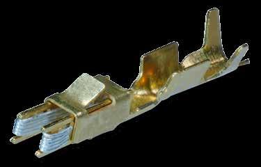
11 ODU SPRINGTAC ODU SPRINGTAC (Contact with Springwire Technology) Socket for crimp termination Q Ø d Ø D ODU SPRINGTAC g s l Suitable for solid pins (page 13/14) Easy and quick connection by crimping (crimp information starting on page 35) Suitable for connecting harmonized cables Part number Dimensions Mechanical data 1) Electrical data 1) Part number crimping tool d D l s g Q = Anschlussquerschnitt in mm² Mating force in N Demating force in N Nominal current in A Max. Continuous current in A Surge current in ka Contact resistance in µω See table on page 38 Other variants, sizes and finishes available on request. See "Technical Information" starting on page 41. Page 11
12 ODU SPRINGTAC ODU SPRINGTAC (Contact with Springwire Technology) Socket completely open D B E K C Suitable for solid pins (page 13/14) Can be connected at both ends Part number Dimensions Mechanical data 1) Electrical data 1) Contact D K B C M E Mating force in N Demating force in N Rated current in A Max. Continuous current in A Surge current in ka Contact resistance in µω Other variants, sizes and finishes available on request. See "Technical Information" starting on page 41. Page 12
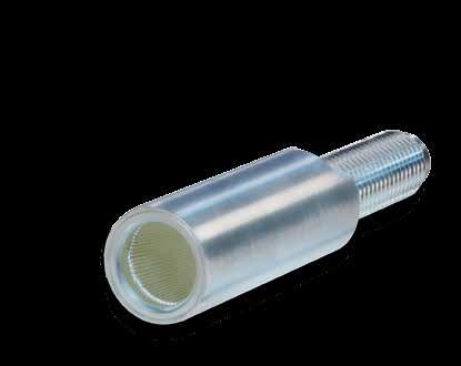
13 ODU SPRINGTAC Solid Pins with Solder / Screw Termination for all ODU SPRINGTAC and ODU LAMTAC Sockets SW ODU SPRINGTAC M Ø Q Ø d Ø D g l s Suitable for all round ODU SPRINGTAC and ODU LAMTAC sockets Suitable for screwing to power busbars, backplanes and contact blocks Cables with cable lugs can be easily connected Cables can be soldered into the solder hole Part number Dimensions d Tolerance d D l s SW g M = Thread Q Other variants, sizes and finishes available on request. Page 13
14 ODU SPRINGTAC Solid Pins with Crimp Termination for all ODU SPRINGTAC and ODU LAMTAC Sockets Q Ø d Ø D g l s Suitable for all round ODU SPRINGTAC and ODU LAMTAC sockets Easy and quick termination by crimping Suitable for connecting harmonized cables Part number Dimensions Part number for crimping tool d Tolerance d D l s g Q = Termination cross-section in mm² Other variants, sizes and finishes available on request. See table on page 38 Page 14
 Electrical data 1) Without spark protection")

15 ODU SPRINGTAC Externally flexed Contact Pins for Solder / Screw Termination M Ø d H9 h ODU SPRINGTAC g e L s k Suitable for solid ODU sockets (page 17) and contact holes d H9 Cables with cable lugs can be easily connected Cables can be soldered into the solder hole Available with and without spark protection Part number Dimensions Mechanical data 1) Electrical data 1) Without spark protection With spark protection d k s S1 L e h g M = Thread Mating force in N Demating force in N Nominal current in A Max. Continuous current in A Contact resistance in µω Other variants, sizes and finishes available on request. See "Technical Information" starting on page 41. Page 15
16 ODU SPRINGTAC Externally flexed, flexible Contact Pins for Solder / Screw Termination M Ø d H9 h g e L s k Suitable for solid ODU sockets (page 17) and contact holes d H9 Cables with cable lugs can be easily connected Cables can be soldered into the solder hole Part number Dimensions Mechanical data 1) Electrical data 1) d k s L e h g M = Thread Mating force in N Demating force in N Nominal current in A Max. Continuous current in A Contact resistance in µω Other variants, sizes and finishes available on request. See "Technical Information" starting on page 41. Page 16
17 ODU SPRINGTAC Solid ODU Connectors for externally flexed ODU Contact Pins with Solder / Screw Termination M Ø Q Ø d Ø D ODU SPRINGTAC K s l Suitable for spring-loaded contact pins Easy installation Cables with cable lugs can be easily connected Cables can be soldered into the solder hole Part number Dimensions d (contact) D l K S M = Thread Q Other variants, sizes and finishes available on request. Page 17
18 For your notes Page 18

19 ODU SPRINGTAC Flatsockets (Flat Contact with Springwire Technology) ODU SPRINGTAC Flatsockets Especially in the automotive industry but also in many other areas, flat contacts or square contacts that are installed into commonly available series production connectors are often used at the electronic interfaces. Usually the square and flat pins are on the electronics and the matching flat sockets are on the cable side. The pins are also used as test interfaces during series production of electronic units; this means that the electronic units are already inserted during production. But the stamped flat sockets available on the market are generally unsuitable for the corresponding test adapter, because these sockets are not designed for high numbers of mating cycles. ODU has developed the SPRINGTAC flat sockets specifically for this test application. Here high mating cycles combine with a contact structure that is plug and assembly compatible. It is the perfect test contact for flat contact pins and square pins. Page 19
20 ODU SPRINGTAC Flatsockets ODU SPRINGTAC Flatsockets (Flat Contact with Springwire Technology) For more than 50,000 mating cycles Many flat contacts (pins) are used in automotive electronics and in apparatus engineering. The sockets for the series production connectors available on the market are stamped contacts, which are crimped to cables and engaged in insulators. These stamped socket contacts of series production connectors allow only a very limited number of mating cycles and are also not suitable for testing because of the very large mating forces required in some cases. ODU has developed springwire flat sockets that are ideally suitable for measurements and testing. Essential characteristics: Assembly-compatible with series production contacts that are already on the market (for example, the AMP Timer). Consequently, engagement with existing series production insulators is also possible. Chamber dimensions, see page 49/50 Version for 2-point measurement (crimp termination) and 4-point measurement = Kelvin measurement (solder termination) Version for 2-point measurement also as quick-change head for many millions of mating cycles ODU SPRINGTAC Flatsockets for flat pins Testing in the automotive sector Flatsocket Flatpin Testing electronics Adapter cable ODU-MAC Socket piece Test piece (for example ECU= Electronic Control Unit) Pallet Page 20
21 ODU SPRINGTAC Flatsockets ODU SPRINGTAC Flatsockets (Flat Contact with Springwire Technology) For 2-point measurement with crimp termination A C B F E L D F The springs are supported by a stamped frame. All contact parts are at the same potential. For instance, these contacts are used if stronger currents have to be transferred or if there are small changes in the volume resistance with signal currents without interfering influence. ODU SPRINGTAC Flatsockets Part number Dimensions Mechanical data 1) Electrical data 1) Surface Size For pin Termination cross-section in mm² A B C D E F L Mating force in N Demating force in N Nominal current in A Max. continuous current in A Contact resistancein mω Ag Au ± 1 1 ± Ag Au ± ± Ag Au ± 2 3 ± Ag Au Ag Au ± 2 5 ± ± 2 5 ± Page 21
 and a back side (connection piece).")

22 ODU SPRINGTAC Flatsockets ODU SPRINGTAC Flatsockets (Flat Contact with Springwire Technology) for 2-point measurement in the quick-change head A C B D F I Ø K E G H F F Connectors according to the ODU quick-change head principle consist of a replaceable front side (insertion piece) and a back side (connection piece). The front side is made of insulator and springwire flat contacts with round connection pins. These are plugged into round springwire contacts. When the flat contacts are worn, the front side can be replaced in a very short time, without having to separate the connections that are connected to the contacts of the back piece. You will find the appropriate connecting parts on page 10 and 11. Material: CuZn alloy Part number Dimensions Mechanical data 1) Electrical Data 1) Surface Size For pin A B C D E F G H I K Mating force in N Demating force in N Nominal current in A Max. continuous current in A Contact resistance in mω Ag Au ± ± 1 1 ± Ag Au ± ± ± Ag Au ± ± 2 3 ± Ag Au ± ± 2 5 ± The quick-change head principle Mated Unmated Exchange part ODU SPRINGTAC Flatsocket Base: ODU SPRINGTAC Socket (wired contacts) In case of service or wear the ODU SPRINGTAC Flatsocket can be replaced in seconds. The wired contacts are simply plugged into the new socket. Page 22
23 ODU SPRINGTAC Flatsockets ODU SPRINGTAC Flatsockets (Flat Contact with Springwire Technology) For 4-point measurement (Kelvin measurement) with solder termination A C G F ODU SPRINGTAC Flatsockets E D B In this contact, the spring supporting parts are isolated from each other. This contact arrangement is used when low electrical resistances have to be measured with high precision. Material: CuZn alloy Part number Dimensions Mechanical data 1) Electrical Data 1) Surface area Size For pin connection in mm² A B C D E F G Mating force in N Demating force in N Nominal current in A Max. continuous current in A Contact resistance in mω Ag Au Löt ± 2 3 ± Ag Au Löt ± 2 5 ± Page 23
24 For your notes Page 24
25 ODU LAMTAC (Contact with Lamella Technology) ODU LAMTAC Page 25
26 ODU LAMTAC ODU LAMTAC (Contact with Lamella Technology) Socket for Solder / Screw Termination SW M Ø Q Ø d Ø D g s l Suitable for solid pins (page 29 / 30) Suitable for screwing to power busbars, backplanes and contact blocks Cables with cable lugs can be easily connected Cables can be soldered into the solder hole Part number Dimensions Mechanical data 1) Electrical Data 1) d D l s SW g M = Thread Q Mating force in N Demating force in N Nominal current in A Max. Continuous current in A Surge current in ka Contact resistance in µω Other variants, sizes and finishes available on request. 1 See "Technical Information" starting on page 41. Page 26
 Suitable for connecting harmonized cables Part number Dimensions Mechanical Data 1) Electrical Data 1) Part number for crimping tool ODU LAMTAC d D l s g Q = Termination")
27 ODU LAMTAC ODU LAMTAC (Contact With Lamella Technology) Socket for Crimp Termination Q Ø d Ø D g s l Suitable for solid pins (page 29 / 30) Easy and quick termination by crimping (Crimp information starting on page 35) Suitable for connecting harmonized cables Part number Dimensions Mechanical Data 1) Electrical Data 1) Part number for crimping tool ODU LAMTAC d D l s g Q = Termination cross-section in mm² Mating force in N Demating force in N Nominal current in A Max. Continuous current in A Surge current in ka Contact resistance in µω See table on page 38 Other variants, sizes and finishes available on request. 1 See "Technical Information" starting on page 41. Page 27
 Elektrische Data 1) d D k s M = Thread Format LF1 178.346.100.201.000 1.5 7.0 7.0 5.5 4 4 3 0.5 20 40 2.0 350 178.347.")


28 ODU LAMTAC ODU LAMTAC (Contact with Lamella Technology) Socket with outer thread LF 1 Ø D Ø d M Ø d M s k k LF 1 LZ 1 LZ 1 Suitable for solid pins (page 29 / 30) Suitable for screwing to power busbars, backplanes and contact blocks Part number Dimensions Mechanische Data 1) Elektrische Data 1) d D k s M = Thread Format LF Format LZ Mating force in N Demating force in N Torque in N Nominal current in A Max. Continuous current in A Surge current in ka Contact resistance in µω Other variants, sizes and finishes available on request. 1 See "Technical Information" starting on page 41. Page 28


29 ODU LAMTAC Solid pins with Solder / Screw Termination for all ODU SPRINGTAC and ODU LAMTAC Sockets SW M Ø Q Ø d Ø D g l s Suitable for all round ODU SPRINGTAC and ODU LAMTAC sockets Suitable for screwing to power busbars, backplanes and contact blocks Cables with cable lugs can be easily connected Cables can be soldered into the solder hole ODU LAMTAC Part number Dimensions d Tolerance d D l s SW g M = Thread Q Other variants, sizes and finishes available on request. Page 29

30 ODU LAMTAC Solid Pins with Crimp Termination for all ODU SPRINGTAC and ODU LAMTAC Sockets Q Ø d Ø D g l s Suitable for all round ODU SPRINGTAC and ODU LAMTAC sockets Easy and quick connection by crimping Suitable for connecting harmonized cables Part number Dimensions Part number for crimping tool d Tolerance d D l s g Q = Termination cross-section in mm² See table on page 38 Other variants, sizes and finishes available on request. Page 30


31 Special Solutions Application-specific solution There are countless possible applications for the springwire and lamella technologies. Many applications naturally demand a specific design for the contacting. Special Solutions The following are examples of some application-specific solutions with lamella technology and springwire technology which we have implemented to our customers' satisfaction. Page 31


 20 / 40 mm: Rated current 500 A (2 ) Special design for use")
 ( 4,0 mm / 4,7 mm and 4,8 mm) with plastic insulation as protection against accidental contact.")
32 Special Solutions Application Specific Solutions Based on ODU Single Contacts As a specialist for customized solutions, ODU has many skills: for example, in development, in tool making in its own tool shop, and in turning, stamping, surface plating, manufacturing assembly machines and cable assembly. With all these options ODU can "tailor" the required connections for the customer. When is a custom-made production worthwhile? Are the development effort, tool-making and production costs in a reasonable proportion to the quantity and to the unit price? ODU's many years of experience enable it to give you fast and competent information. ODU SPRINGTAC contacts for transferring welding current in tool-changing systems: Tested up to 1 million mating cycles Interchangeable crimp terminations up to 35 mm² Load current up to 200 A Coaxial power connector constructed with ODU SPRINGTAC (contacts with springwire technology) 20 / 40 mm: Rated current 500 A (2 ) Special design for use in the lower LF range Special termination for coaxial wire management ODU SPRINGTAC (contact with springwire technology) ( 4,0 mm / 4,7 mm and 4,8 mm) with plastic insulation as protection against accidental contact. Special versions are available for applications at higher temperatures. ODU LAMTAC (contact with lamella technology) with application-specific cable termination in welding technology. Page 32


 Rated current 25 A Vibration-resistant Application")
33 Special Solutions Application Specific Solutions based on ODU Single Contacts Connector with ODU SPRINGTAC (Springwire Technology) Power supply socket for silicon wafer production: Rated current 720 A Contact diameter 30 mm Robust design for industrial use Special termination using standard ODU LAMELLA 22 mm in special carrier for high-performance securing: Rated current ca. 550 A Special Solutions ODU SPRINGTAC with guide funnel 26 mm Floating mounting on one contact side Funnel allows larger radial displacement Application in the automotive sector: Special lamella with radial compensation (± 0.3 mm) Rated current 25 A Vibration-resistant Application temperature - 40 C to +125 C, briefly +170 C Page 33
34 For your notes Page 34

35 Tools and Termination Technology Tools and Termination Technologies Page 35
 with a melting temperature below the melting temperatures of the base materials that are to be joined.")
 and nuts.")

36 Tools and Termination Technologies Termination Technology ODU offers three different contact termination technologies for the single contacts: Solder Screw Crimp Solder termination Soldering is a procedure to join metal components with the help of a molten joining metal (solder) with a melting temperature below the melting temperatures of the base materials that are to be joined. In contrast to crimping, the wire to be soldered can also be considerably smaller than the intended solder hole. Warning: avoid unacceptable temperature increases in sockets. Cross-section of hexagonal crimping Screw termination This method of terminating cables is usually done using cable lugs with serrated washers (flat washers) and nuts. Washers and nuts are not part of the standard delivery program (supplied if needed). Crimp termination Contacting by crimping in order to produce connection lines results in a permanent, corrosion-free and securely contacted connection. Crimping is a time-saving procedure that can be performed by non-experts. The cold pressing (crimping) causes the conductor and contact material to be compressed at the pressure point in such a way that an almost gas-tight connection is produced that resists pulling to an extent that depends on the conductor material. Crimping can be done both on the smallest cross-sections and on large ones. Smaller cross-sections ( mm²) generally require 8-point crimping tools and the larger ones generally require hexagonal crimping tools. The width across corners of the crimping is no larger than the original diameter. The insulation of the cable is not damaged and can be brought up to the contact end. Contacts with 8-point crimping Sectional image of hexagonal and 8-point crimping: For the 8-point crimping, two 4-point crimpings lie one behind the other. For a proper crimp, the diameter of the hole must be precisely matched to the cable. Proper crimping of our contacts can only be guaranteed with the crimping tools recommended by ODU. In order to advise you, we must know the type of cable and the cable cross-section, preferably with a sample and a datasheet. Page 36

. The crimping tool has a locking system that prevents it from opening before the pressing has been completed.")


37 Tools and Termination Technologies Crimping Tools * Suitable for all round ODU SPRINGTAC and ODU LAMTAC Sockets and Pins The crimping tools and their crimping inserts are designed for the necessary compression forces and with a locking system that prevents tools from opening prematurely. Opening is possible only after pressing at the required pressure has been completed. 8-point crimping tool It is suitable for cross-sections from 0.08 to 2.5 mm² (AWG28 AWG12). The crimping tool has a locking system that prevents it from opening before the pressing has been completed. It is provided with a user-friendly digital display. Part Number: Hexagonal crimping tool This is suitable for cross-sections of 1.5 mm², 2.5 mm², 4.0 mm² and 6.0 mm². The crimping tool has a locking system that prevents it from opening before the pressing has been completed. Part Number: Tools and Termination Technologies Hydraulic crimping tool It is suitable for cross-sections of 10 mm² and 50 mm². The crimping tool has a locking system that prevents it from opening before the pressing has been completed. It is provided with a safety valve that opens automatically as soon as the pressure required for complete compression has been reached. Part Number: Hydraulic crimping tool For cross-sections from mm². Part number for cross-section mm²: mm²: mm²: * Table for adjustment and contact holder (positioner) see next page. Page 37
38 Tools and Termination Technologies Crimping data: tools for crimp contacts Crosssection Part number Gauge / profile mm² Crimping tool Crimp insert The inserts must be ordered separately for 10 mm² or more >0.65 < >0.90 < ) >1.40 < Profil Profil Profil Profil Diameter "D" <4.5 mm required Page 38


.")
39 Tools and Termination Technologies Crimping Tools For ODU SPRINGTAC Flatsockets B profile crimping tool For ODU SPRINGTAC Flatsocket Cross-sections mm². Part Number: B profile crimping tool For ODU SPRINGTAC Flatsocket Cross-sections mm². Part Number: Size Crosssection mm² Crimping tool Profile Positioner 0.64 x Profile 0.25 Position x Profile 0.35 Position x Profile 0.5 Position x 0.6 / Profile x Profile x Profile x Profile 3 Screw termination Tightening torques Connection thread Tightening torque Maximum in Nm M2 0.2 M3 0.5 M4 1.2 M5 2.0 M6 3.0 M8 6.0 M M M M M M Maximum tightening torque with solid screw termination and standard support material (brass). Tools and Termination Technologies Page 39
40 For your notes Page 40

41 Technical Information Technical Information Page 41
42 Technical Information Principles of Current Carrying Capacity Derating measurement precedure (DIN EN : 2002) Structure of the basis curve Current I l3 t3 Upper limit temperature given by the materials t2 l2 t1 l1 t3 t2 t1 Ambient temperature t A connector's current-carrying capacity is determined by measurement. It is determined by taking into account the self-heating due to Joule heat and the ambient temperature, and is limited by the thermal properties of the contact materials used; the upper limit temperatures of these materials should not be exceeded. The relationship between current, the temperature increase caused as a result of the power dissipation at the contact resistor and the ambient temperature is depicted in a curve. The curve is drawn in a linear coordinate system with the current "I" as the ordinate and the temperature "t" as the abscissa. The upper limit temperature is used as a limit for the diagram. In three measurements, the temperature rise due to Joule heat (Δt) is determined at different currents in at least three connectors and the points determined in this process are connected into a parabolic basis curve. The corrected current-carrying capacity curve (derating curve) can be derived from the basis curve. The safety factor (0.8 I n ) can be used to give consideration to such values as manufacturing tolerances as well as to uncertainties in the temperature measurement and in the measurement setup. Page 42
43 Technical Information Current Carrying Capacity Diagramm for ODU SPRINGTAC (Contact with Springwire Technology) Current carrying capacity in amperes Ambient temperature in C Temperature rise due to Joule heat in K 1 1,5 2 2, Technical Information Nominal current Max. continuous current Measurement made in accordance to DIN EN (basis curve derived shown). Upper limit temperature: +120 C. Termination with nominal cross-section. Page 43
44 Technical Information Current Carrying Capacity Diagramm for ODU LAMTAC (Contact with Lamella Technology) Current carrying capacity in amperes Ambient temperature in C Temperature rise due to Joule heat in K 1, Nominal current Max. Continuous current Measurement according to DIN EN (basis curve is shown). Upper limit temperature +150 C. Connection with the largest specified cross-section. Page 44
45 Technical Information Reduction Factors Number of loaded wires Reduction factors 1) This table shows the reduction factors in cable clusters. Extract from DIN VDE Table 26 Conversion factors for multi-core cables with lines having cross-sections up to 10 mm². 1 Acc. to DIN VDE 0298 part 4 Technical information Page 45
 or both sides should always have a \"floating\" mounting in order to compensate for manufacturing and assembly tolerances of the individual system components.")


46 Technical Information Installation Instruction ODU contact systems are used both as single contacts and in multi-pin connectors. One side (pin or socket side) or both sides should always have a "floating" mounting in order to compensate for manufacturing and assembly tolerances of the individual system components. ODU contact systems are not suitable for guiding a plug-in system. Components should be separately provided in order to implement a preliminary guidance piece. Preliminary guidance pieces are always recommended. permanently mounted one-way floating both-sided floating Our ODU SPRINGTAC and ODU LAMTAC contact series are able to compensate for the radial displacements of the insertion axis. The figure shows a cross-section through a mated contact pair with a radial axis shift. The contact springs or contact bars are still on the mating surfaces and consequently continue to ensure full contact reliability. r r Mated with concentric axis Mated with radial axis shift Δr Nominal contact diameter 2mm 4 mm 14 mm 30 mm Max. Δr 0.02 mm 0.05 mm 0.10 mm 0.20 mm The deviation angle α of the insertion axis of the pin and socket should be max. ± 1. It is especially important to consider this when implementing a "floating" assembly position. Page 46

47 Technical Information Maintenance Kits for ODU SPRINGTAC and ODU LAMTAC Contacts Contact lubrication improves the mechanical characteristics of contact systems. We recommend that the contact surfaces also be cleaned before being lubricated in order to remove impurities. With proper care, it is possible to minimize significantly the wear caused by frequent matings and to reduce the mating and demating forces. The cleaning and lubrication interval must be adapted individually to the conditions, and these steps should be carried out only with products recommended by the contact manufacturer. ODU has put together a maintenance kit for this step so that you can carry out lubrication directly at your site. A cleaning brush and a special cleaning cloth, together with precise instructions, allow optimal care of the contacts. The maintenance kit can be used for all ODU contacts and connectors as long as no other specifications apply. Part number: Technical characteristics of the maintenance kit can be found on our website: /en/downloads.html Technical Information Page 47
48 Technical Information Conversions AWL Cross Section (AWG = American Wire Gauge) The AWG system describes the cross section of a wire using a gauge number for every 26 % increase in conduc tor cross section. With larger wire diameters, the AWG gauge numbers decrease; as the wire sizes increase, the AWG gauge numbers decrease. This is only valid for solid conductors. Most wires are made with stranded conductors. Compared to solid conductors stranded wires offer higher durability, higher flexibility and better performance under bending and vibration. Stranded wires are made from wires with smaller gauge sizes (higher AWG gauge number). The AWG gauge num ber of the stranded wire is equal to that of a solid conduc tor of the same size wire. The cross section of the stranded conductor is the sum of cross sections of the single con ductors. For example, a AWG-20 stranded wire of 7 AWG-28 con ductors has a cross section of mm²; an AWG-20 stranded wire with 19 AWG-32 conductors has a cross section of mm². Conversion table: AWG mm² Circular wire AWG Diameter Crosssection Weight Max. resistance Inch mm mm² kg/km Ω/km 10 (1) (37/26) (1) (19/25) (37/28) (1) (19/27) (37/30) (1) (19/29) (1) (19/30) (1) (7/28) (19/32) (1) (7/30) (19/34) (1) (7/32) (19/36) (1) (7/34) (19/38) (1) (7/36) (19/40) (1) (7/38) (19/42) (1) (7/40) (19/44) (1) (7/42) (1) (7/44) (1) (1) (1) (1) Page 48
49 Technical Information ODU SPRINGTAC Flatsockets (Contact with Springwire Technology) Chamber dimensions for 0.64 x ) Chamber dimensions for 1.6 x 0.6 / 0.8 Technical Information Page 49
50 Technical Information ODU SPRINGTAC Flatsockets (Contact with Springwire Technology) Chamber dimensions for 2.8 x 0.8 2) Chamber dimensions for 6.3 x 0.8 (4.8 x 0.8) 2) Dimensions without tolerance statement in accordance to DIN ISO 2768 fine 1) Version with groove for secondary locking 2) Slightly increased mating and demating forces result for the articles and Page 50
51 Technical Information Technical Information / Definitions / Terms AWG See page 48. Basis curve Metrologically established current-carrying capacity curve for connectors according to the measurement procedure described in EN :2002 depending on the permissible limit temperature of the materials. Crimping Termination technology in which a non-detachable, solderless electrical and mechanical connection is carried out by compression or pressure forming of the crimp barrel around the conductor. Current-carrying capacity (Nominal and maximum continuous current) The information refers to adequately sized connection cable according to DIN VDE 0295 (EN 60228) Class 5, so that this does not cause any further temperature increase. The stated temperature increase is from the contact. The values that are given are average values. Derating curve The corrected current-carrying capacity curve, derived from the determined basis curve (0.8 ln). It takes into account manufacturing tolerances and uncertainties in the temperature measurement and in the measurement conditions. Derating measurement method (DIN EN ) Measuring method that determines the current-carrying capacity of connectors, taking into account the maximum permissible limit temperature. Limit temperature The highest permissible temperature at which a connector is allowed to be operated. It includes contact heating due to the current-carrying capacity. The limit is +120 C for standard springwire contacts and +150 C for standard lamella contacts. For high temperature applications, please contact ODU. Lubrication All standard contacts are lubricated before leaving the factory. For re-lubrication we recommend the ODU maintenance kit (see page 47). Materials (standard version) Pins and carriers of the sockets are silver-plated and made of a CuZn alloy. The lamellas are made of a CuBe alloy and are also silver-plated. The wires of the springwire contacts are made of a CuSn alloy and are also silver-plated. Mating cycles Mechanical operation of connectors and plug-in devices by mating and demating. One mating cycle comprises one mating and one demating process. The default value for lamella contacts is 10,000 mating cycles, for flat sockets 50,000 mating cycles and for springwire contacts 100,000 mating cycles. These values are valid only under the following conditions: Clean environment Adequate radial guidance Flawless counter pins. Mating or demating force For lamella contacts, the information refers to lubricated contacts (condition at delivery) and after approximately 30 mating cycles. The forces are higher for new contacts (lubricated). For springwire contacts, the information refers to contacts in new condition. The information refers to silver-plated surfaces. The provided values are averages with a possible deviation of ±50 %. Maximum continuous current The current intensity, determined by measurement at room temperature (around 20 C), which causes a rise in the contact temperature up to limit temperature. Nominal current The current intensity determined by measurement which causes a contact temperature rise of 45 Kelvin. It is determined according to the derating measurement method (DIN EN : 2002) and derived from the basis curve. Solder connections Termination technology in which two metallic materials are connected to each other with the help of a melted metal (solder) whose melting temperature is lower than the melting temperatues of the base materials that are to be connected. Technical Information Page 51
52 Technical Information Technical Informations / Definitions / Terms Surge current Single pulse current with a load duration time of 10 ms. Termination technologies Methods for connecting the cables to the electromechanical devices, for example solderless connections according to DIN EN 60352: Crimp, solder or press-in connections, etc. (see page 36). Contact resistance The total resistance from termination to termination. The interface resistance is considerably less than the volume resistance. The values given here are average values. Suitable precautions must be taken in order to ensure that people do not come into contact with live conductors during installation or operation. All entries were reviewed with utmost diligence before this catalogue was printed. ODU reserves the right to change the design and performance of any product in order to meet changing technical developments without prior notice. ODU reserves the right to discontinue any part in this catalogue without prior notice and without obligation to continue production after the change. Page 52


53 Company Information Page 53 Company Information


54 Company Information Quality Management ODU has had a powerful quality management system in place for years. ODU has been successfully certified to ISO 9001 since In addition, the automotive sector of the company is certified to ISO TS The certification process was carried out by the internationally active BVQI (Bureau Veritas Quality International) company. ODU is also certified according to the medical standard ISO 13485: AC: In addition, ODU is certificated to DIN EN ISO 14001: 2009 as well as to different certifications: VDE, UL, UL wiring harness, SCA, VG and MIL. Page 54


55 Company Information Your Partner in Many Application Areas ODU stands for quality, flexibility and reliability. This is why customers working in many application areas rely on ODU products in markets such as the following: Medical Industrial Measuring and testing Military and security Energy Automotive Page 55 Company Information

56 Company Information The Complete ODU Product Range Single contacts (round or flat) High current connectors Circular connectors with Push-Pull locking Modular rectangular connectors PCB connectors Robust connectors Disposable systems Application specific solutions AMC - Advanced Military Connector Cable assembly Page 56

57 Company Information Everything from one source: ODU the system supplier Each connection needs its individual cable. Make no compromises when it comes to the quality of the complete connection system. ODU gives you the complete system solution from one source, with no intermediary suppliers. Cable assembly is a very complex subject. It requires equal measures of expertise in the areas of connectors, cables and assembly. ODU meets all these requirements in full. Our competent assembly team tests the complete system according to your specifications. Our assembly service promises you the same quality found in our connectors without compromises. ODU offers you everything from one source 100% final inspections Production in clean room according to EN ISO possible Automated processes (cutting, stripping, attaching) Extrusion possible with a hot-melt and high pressure / temperature process Ultrasound welding EMC-compatible assembly Application specific labelling Widest range of potting possibilities for sealed systems Extruded cable crossovers Advantages for the customer Modern manufacturing facilities in Mühldorf (Germany), Shanghai (China), and Sibiu (Romania) Reliability thanks to our company-wide quality strategy Products with durability and functional reliability Production according to UL (file:e333666) possible Inspections, such as crimp force monitoring, during production Page 57 Company Information

58 Company Information Application Specific Connectors Innovative, dynamic markets call for innovative connectors. As an expert for special applications and requirements, we develop forward-looking, appropriate connectors attuned to your needs! In spite of the global trend toward standardized connectors, there are always applications that call for an application-specific solution. We accept this challenge and develop innovative products for our customers based on our many years of extensive know-how, our creativity and, not least, our high level of vertical integration. Technology access and technology mastery, combined with intensive cooperation with the user, form the basis for achieving success together. Design-to-cost is joined by design-for-application for the customer's benefit. Page 58
59 For your notes Page 59 Company Information

60 ODU worldwide ODU GmbH & Co. KG Pregelstr Mühldorf a. Inn Germany Phone: Fax: ODU France Phone: odu@odu.fr ODU Scandinavia Phone: sales@odu.se ODU UK Phone: sales@odu-uk.co.uk ODU USA Phone: sales@odu-usa.com ODU Shanghai Trading Phone: oduchina@odu.com.cn You can find more qualified representatives list on our web page: /sales
ODU ELECTRICAL CONTACTS
 ODU ELECTRICAL CONTACTS Contact technologies for the most demanding of requirements. Up to 1,700 A, 100,000 mating cycles and more. ODU SPRINGTAC ODU LAMTAC ODU TURNTAC ODU STAMPTAC ODU ELECTRICAL CONTACTS
ODU SPC Single POWER Connector
 Catalog ODU SPC Single POWER Connector ODU Steckverbindungssysteme GmbH & Co. KG, Pregelstraße 11, D 84453 Mühldorf / Inn Tel.: +49/8631/6156-0, Fax: +49/8631/6156-49, E-Mail: zentral@odu.de, www.odu.de
CONTACT EXPERTISE FOR THE FUTURE OF MOBILITY
 CONTACT EXPERTISE FOR THE FUTURE OF MOBILITY Contact technologies and connectors from ODU. www.odu-connectors.com THE FUTURE IS IN THE CONNECTION The emobility market is already a key market of the future
ODU DOCK. Connector System for application in Robot-Docking and Tool-Changing Systems for more than plugging cycles
 Catalogue No.: 1014-b ODU DOCK Connector System for application in Robot-Docking and Tool-Changing Systems for more than 100.000 plugging cycles All dimensions in mm. All figures are illustrations or photos.
Han K 3/0, K 3/2 / Han HC Modular. Contents Technical characteristics Han K 3/0, Han K 3/ Inserts Han K 3/0, Han K 3/
 Han K 3/0, K 3/2 / Han HC Contents Page Technical characteristics Han K 3/0, Han K 3/2... 14.02 Inserts Han K 3/0, Han K 3/2... 14.03 Hoods/Housings Han 24 HPR for Han K 3/0, Han K 3/2... 14.04 Technical
Directory chapter 03 DIN Power (to 15 A) Types H, H 3, MH , MH Technical characteristics type H
 Types H, H 3, MH , MH Technical characteristics type H") Directory chapter 03 () Types H, H 3, MH 24 + 7, MH 21 + 5 Page Technical characteristics type H.................................... 03.10 Type H connectors.................... 03.11 Type H 3 connectors..................
Directory chapter 03 () Types H, H 3, MH 24 + 7, MH 21 + 5 Page Technical characteristics type H.................................... 03.10 Type H connectors.................... 03.11 Type H 3 connectors..................
Medium-voltage fuses 3 kv 40.5 kv, 0.4 A 315 A
 DISTRIBUTION SOLUTIONS Medium-voltage fuses 3 kv 40.5 kv, 0.4 A 315 A Continuous protection and reliable operation Proven design and compliance with newest fuses standards Compatibility with other ABB
20 HUBER+SUHNER RADOX SOLAR
 All our cables fully comply with the European directives 76/769/EWG, 2003/11/EG, 2000/53/EG, 2003/53/EG and 2002/95/EG (RoHS) and the requirements of REACH Nr. EC1907/2006. 20 RADOX SOLAR cables RADOX
CONTACT EXPERTISE FOR THE FUTURE OF MOBILITY
 CONTACT EXRTISE FOR THE FUTURE OF MOBILITY Contact technologies and connectors from ODU. www.odu-usa.com THE FUTURE IS IN THE CONNECTION The emobility market is already a key market of the future with
MDual Power Connector
 MDual Power Connector Overview Utilizing the efficient high-current design of the PowerBud contact technology, the MDual power connectors carry high power in a small package and features self-aligning
Han Q 1/0 Axial Screw Protected. Available February 2017
 Features Compact connector based on size 3 A with a current carrying capacity of 100 A Space saving design due to an angled malemale version IP20 protected male and female contact according to IEC 60 529
Power distribution components
 Industrial electronics Power distribution components Reliable, cost-effective, complete R England sv_001.fm Rittal power distribution components Bar centre distance (mm) Number of poles Busbar dimensions
Spring hangers, spring supports
 Spring hangers, spring supports 2 spring Spring hangers, supports PRODUCT 2 GROUP Spring hangers, spring supports Contents Page Field of application...2.1 Overview of spring hangers and spring supports...2.3
Corporate Standard 0001/MUC_EN Protective Conductor Connection
 Corporate Standard 0001/MUCEN 1 History Version Valid from Author Modification 1st July 2008 K. Wianski / A.Triebe First edition 2 Scope of Application This corporate standard shall apply to combinations
Guide units. For toolmaking, fixture manufacturing and machine engineering
 Guide units For toolmaking, fixture manufacturing and machine engineering Guide units in compliance with DIN, ISO and STEINEL standards or according to your specifications Guide pillars Guide and pillar
FUSES. Safety through quality
 Safety through quality HH HIGH VOLTAGE Over many decades SIBA has developed a global product line of High Voltage Fuses that are comprehensive for any and all applications. Superior engineering, advanced
BRUSH-HOLDER PLUG SETS CATALOGUE
 BRUSH-HOLDER PLUG SETS CATALOGUE Introduction Table of Contents 1 Introduction... 2 2 System Description... 3 2.1 Subsystems and Components... 3 2.2 Function... 4 2.3 Brush Clamping... 4 2.4 Electrical
General notes. Operating conditions
 1 General notes Wöhner busbar systems and components are the result of expert development based on many years of experience. They have been exhaustively tested and hold many approvals. The correct selection
RE / STAR Tolerance Rings STAR Ball Knobs, Knob and Lever Type Handles
 RE 2 970/.99 STAR Tolerance Rings STAR Ball Knobs, Knob and Lever Type Handles STAR Tolerance Rings Product Overview Tolerance rings are made of hard, embossed spring steel strip and belong to the class
SLE SLE CHARACTERISTICS. Travel. Travel speed. Acceleration. Temperature. Special types. closed + open. application fields SLE
 SLE SLE applications 81 SLE dimensions 82 SLE types 84 SLE sizes 86 SLE parts 87 SLE assembly 88 SLE connectors 83 SLE part numbers 92 SLE accessories 98 load / (kg/m) inner height / (mm) 60 LOAD DIAGRAM
Han-Power Energy Bus Components
 HARTING Electric Han-Power Energy Bus Components People Power Partnership Han Data Sheet 0080-7 Han-Power T Han-Power T Part-Number Drawing Dimensions in mm 09 12 008 4701 Cable gland please order separately
ODU MEDI-SNAP. Miniature Cylindrical Connectors with Push-Pull-Locking in Plastic
 Catalogue No.: 005ME-c-e ODU MEDI-SNAP Miniature Cylindrical Connectors with Push-Pull-Locking in Plastic 2 rue René Laennec 5500 Taissy France Fax: 03 26 85 9 08, Tel : 03 26 82 49 29 E-mail:hvssystem@hvssystem.com
Technical Data, High Power 2-way* Cannon APD / ISO Connectors. Electrical Data. Mechanical Data. Environmental Data (acc.
 Technical Data, High Power 2-way* Electrical Data Operating Voltage Operating Current Contact Resistance Voltage Proof Insulation Resistance Mechanical Data 48 VDC* see derating curve 2 mω max. 1000 VAC,
AF09... AF30 3-pole Contactors up to 20 HP / 480 VAC
 AF0... AF0 -pole Contactors up to 20 HP / 480 VAC Contactors and Overload Relays Overview...2 AF0... AF0 -pole Contactors Ordering Details...4 Main Technical Data...20 DC Circuit switching...2 Main Accessory
Miniature Circuit-Breakers (MCBs)
") Product Overview Miniature Circuit-Breakers (MCBs) Design Tripping characteristics Rated current I n Rated breaking capacity Power supply company product range 5SP3 E 16 - A Standard product range 5SQ2
Product Overview Miniature Circuit-Breakers (MCBs) Design Tripping characteristics Rated current I n Rated breaking capacity Power supply company product range 5SP3 E 16 - A Standard product range 5SQ2
PRODUCT SPECIFICATION STANDARD TIMER CONNECTOR, RAST 5mm, 2-12 POSITIONS
 PRODUCT SPECIFICATION STANDARD TIMER CONNECTOR, RAST 5mm, 212 POSITIONS 1. GENERAL: 1.2 Purpose and Scope: This specification describes the structure, properties, design types as well as quality requirements
FISCHER FREEDOM TM SERIES
 K CHAPTER FISCHER TM SERIES EASY MATING EASY CLEANING EASY INTEGRATION KEY FEATURES No key code: 360 mating freedom & optimized cable management Membrane-sealed contacts (patent pending) Low profile IP68
CONEC provides reliable and effective solutions to OEM, EMS and cable houses.
 CONEC CANADA USA CONEC designs and manufactures products in modern facilities. The products are made in accordance to the highest quality standards and industry specifications. CONEC provides reliable
Contents Technical characteristics Han A Technical characteristics Han 3 A with HARAX Termination
 Contents Page... 01.02 3 with HRX Termination... 01.04 3, 3 with HRX Termination... 01.05 4... 01.06 10... 01.07 16... 01.08 32... 01.09 01 Features Metal and plastic version available 3 hoods/housings
S840, S845, S846 Series Single-break changeover, NC or NO contacts, positive opening operation and wiping action Catalogue D40.en
 Snap-action switches S80, S85, S86 Series Single-break changeover, NC or NO contacts, positive opening operation and wiping action Catalogue D0.en Snap-action switches, S80, S85, S86 Series Single-break
Amphenol. eries SJT. Series SJT. VG 96912, Series 1 PAN JN 1003
 Amphenol eries SJT Series SJT VG 96912, Series 1 PAN 6433-2 JN 1003 Ordering information Ordering example: SJT G 06 RT 14-35 P A 014 Series (p. 9, 15, 18) SJT Scoop proof (100% scoop-proof) Junior (Miniature
Axial Piston Fixed Pump A17FNO Series 10
 Axial Piston Fixed Pump A17FNO Series 10 RE 91510 Issue: 06.2012 Replaces: 03.2010 Size 125 Nominal pressure 250 bar Maximum pressure 300 bar For commercial vehicles Open circuit Features Fixed pump with
TEKOFLEX. Four-Wire-Measurement-Systems
 TEKOFLEX Four-Wire-Measurement-Systems 3 Konstruktionsänderung im Interesse der Qualitätsverbesserung vorbehalten. Due to continuous product improvement specifications Konstruktionsänderung may change
Lab Electrical Power Engineering I
 INSTITUT FÜR ELEKTRISCHE MASCHINEN RHEINISCH-WESTFÄLISCHE TECHNISCHE HOCHSCHULE AACHEN Lab Electrical Power Engineering I Test 3: Induction machine with squirrel cage rotor and slip ring rotor 1 Experiment
K CHAPTER FREEDOM TM SERIES EASY MATING EASY CLEANING EASY INTEGRATION FISCHER KEY FEATURES
 K CHAPTER FISCHER TM SERIES EASY MATING EASY CLEANING EASY INTEGRATION KEY FEATURES No key code: 360 mating freedom & optimized cable management Membrane-sealed contacts (patent pending) Low profile IP68
User Manual for the RAMK Rotational Absolute Magnetic Kit Encoder
 VISHAY MCB www.vishay.com Variable Resistors By Frederic Bourget and Emmanuel Lemelle INTRODUCTION The purpose of this user manual is to define the precautions for unpacking, mounting, and using RAMK encoder
TN1250 Technical note
 Technical note Press-fit ACEPACK power modules mounting instructions Introduction ST introduces the ACEPACK Power Module family, designed for easy mounting and reliable performance in rugged applications.
Thermoelectric Module Installation Guidance
 Thermoelectric Module Installation Guidance Introduction The aim of this document is to describe the process for mounting a thermoelectric module for use in a system. Considerations for mounting cooler
8WH2 Spring-Loaded Terminals
 8WH2 Spring-Loaded Terminals /2 Introduction /3 General data on 8WH /7 8WH through-type terminals 1) /18 8WH hybrid through-type terminals 1) /21 8WH fuse terminals /23 8WH isolating blade terminals /25
Proportional pressure relief valve, directly operated, without/with integrated electronics (OBE)
") Proportional pressure relief valve, directly operated, without/with integrated electronics (OBE) ype DBE and DBEE RE 96 Edition: 03-06 Replaces: 04.3 Size 6 Component series 6X Maximum operating pressure
Proportional pressure relief valve, directly operated, without/with integrated electronics (OBE) ype DBE and DBEE RE 96 Edition: 03-06 Replaces: 04.3 Size 6 Component series 6X Maximum operating pressure
THE ADVANTAGES OF BUTT CONTACTS
 THE ADVANTAGES OF BUTT CONTACTS GENESIS Further to a corporal injury witnessed in the 50 s by Mr. Gilles Maréchal while a defective motor was plugged-in, he had the idea to rethink completely how these
6000 Series Buccaneer. Secure, quick connector mating and release. 30 twist locking Tamperproof lock prevents accidental un-mating
 circular that combine the ease of use of a push/pull coupling mechanism with proven environmental sealing. Available with metal or plastic bodies, the range supports both data (USB and Ethernet), signal
Dial thermometers. Gas filled system and Bi-metal. dial thermometers
 JJ Dial thermometers JJ Diesel engine thermometers JJ Low temperature dial thermometers JJ Remote reading dial thermometers JJ Remote reading diesel engine thermometers JJ Remote reading low temperature
Dr. TRETTER AG. Tolerance Rings. safe cost-effective fast assembly
 Dr. TRETTER AG Tolerance Rings safe cost-effective fast assembly Tolerance Rings are corrugated metal strips manufactured of high quality spring steel. Tolerance Rings are a fastening device between two
VDE-registered oil-resistant PVC control cable with black outer sheath for a wide range of applications
 VDE-registered oil-resistant PVC control cable with black outer sheath for a wide range of applications - PVC control cable, VDE registered, oil resistant, flexible and UV-resistant for various applications,
! C A U T I O N! Damages on the machine possible.
 1 The PIK is a connecting element between electro motor and hydraulik pump in combination with an oil - air cooler. General Hints Please read through these mounting instructions carefully before you assemble
General characteristics and technical data Series MCS
 MOD M MC MCS VP 100 S Operating voltage up to 5 kvdc Operating current up to 4,5 A 2-6 high voltage contacts Quick and easy assembling Protection class IP68 acc. DIN EN 60529 General characteristics and
Thermal-cutoff, Fuse and Fuseholder Incorporated into a Simple Compact Device
 Thermal-cutoff, Fuse and Fuseholder Incorporated into a Simple Compact Device It is generally known to employ a fuse for overcurrent protection and a thermal fuse or a thermostat for overheat protection
igus TwisterChain NEW Second Generation: robust, low-noise, for high loads
 igus TwisterChain NEW Second Generation: robust, low-noise, for high loads TwisterChain New robust, low-noise, for high loads Higher loads and smoother running igus new generation of TwisterChain circular
Wedge in Plugs Stock No
 Amphenol Connectors Description Plugs Stock No. Receptacles Stock No. 2-way 38170 38171 3-way 38172 38173 4-way 38174 38175 6-way 38176 38177 8-way 38178 38179 12-way 38180 38181 Wedge in Plugs Stock No.
LED Driver Linear / area dimming
 Driver LC W 0 1050mA 50V IOTr lp PRE UNV PREMIUM series SELV (US applications) Product description Constant current LED Driver Dimming range 1 100 % Adjustable output current between 0 and 1,050 ma via
8WH2 Spring-Loaded Terminals
 8WH2 Spring-Loaded Terminals /2 Introduction /3 General data on 8WH /7 8WH through-type terminals 1) /18 8WH hybrid through-type terminals 1) /21 8WH fuse terminals /23 8WH isolating blade terminals /25
AF series contactors (9 2650)
") R E32527 R E39322 contactors General purpose and motor applications AF series contactors (9 2650) 3- & 4-pole contactors General purpose up to 2700 A Motor applications up to 50 hp, 900 kw NEMA Sizes 00
R E32527 R E39322 contactors General purpose and motor applications AF series contactors (9 2650) 3- & 4-pole contactors General purpose up to 2700 A Motor applications up to 50 hp, 900 kw NEMA Sizes 00
Mounting and operating instructions EB 5801 EN. Electric Actuators Type 5801 (Rotary Actuator) Type 5802 (Linear Actuator)
 Type 5802 (Linear Actuator)") Electric Actuators Type 5801 (Rotary Actuator) Type 5802 (Linear Actuator) Linear Actuator with Type 3260 Control Valve Rotary actuator with lever system Linear actuator with Type 3321 (V2001) Control
Electric Actuators Type 5801 (Rotary Actuator) Type 5802 (Linear Actuator) Linear Actuator with Type 3260 Control Valve Rotary actuator with lever system Linear actuator with Type 3321 (V2001) Control
3NP1 Fuse Switch Disconnectors up to 630 A
 Switch Disconnectors 3NP1 Fuse Switch Disconnectors up to 630 A Introduction Overview All key product features at a glance available for all sizes Connection of circular conductors and laminated conductors
7000 Series Buccaneer
 The all plastic and metal construction of the - circular that combine the ease of use of a quick coupling mechanism with proven environmental sealing for signal and mains power. Designed and independently
CRITO Connection technology. Double and triple T and TCC section busbars
 Centre feed unit 5 Centre feed unit Centre feed unit 5 Centre feed unit up to 4000 A combines the advantages of high short-circuit capacity, drill-free mounting, brace terminal technology and clearly structured
SU200M Datasheet. Branch protection acc. to CSA C22.2 No.5 / UL 489
 MINIATURE CIRCUIT BREAKERS SU200M Datasheet Branch protection acc. to CSA C22.2 No.5 / UL 489 The miniature circuit breaker SU200 M is ABB s solution for UL 489 branch circuit protection up to 480 Y/277
Proportional pressure relief valve, directly operated, rising characteristic curve
 Proportional pressure relief valve, directly operated, rising characteristic curve RE 1139-0/09.07 Replaces: 0.05 1/1 Type KBPS.A (High-Performance) Component series A Maximum operating pressure 0 bar
ORIGA Pneumatic Linear Drives OSP-L
 ORIGA Pneumatic Linear Drives OSP-L Very long lifetime and lowest leakage A NEW Modular Linear Drive System With this second generation linear drive Parker Origa offers design engineers complete flexibility.
AF40... AF96 3-pole contactors Technical data
 Main pole - Utilization characteristics according to IEC Standards IEC 60947- / 60947-4- and EN 60947- / 60947-4- Rated operational voltage Ue max. 690 V Rated frequency (without derating) 50 / 60 Hz Conventional
EFFICIENCY: In order to maximize power, prolong battery life and minimize power requirements, low loss connections assists in managing these.
 1 2 POWER: Consumers do not like to give up anything. They prefer more for less. In addition, they have grown accustom to the convenience of a gas powered vehicle. EFFICIENCY: In order to maximize power,
Directional servo-valve of 4-way design
 Courtesy of CM/Flodyne/Hydradyne Motion Control Hydraulic Pneumatic Electrical Mechanical (0) 426-54 www.cmafh.com Directional servo-valve of 4-way design Type 4WSE3E 32 Size 32 Component series 5X Maximum
USA Canada On the Internet: Toll Free wieland Product Range Electrical Connections
 0.2 F 01/02 270 Excerpt from our master catalogue wiecon PCB terminals In Ageneral, all Wieland components which are obliged to have the identification are provided with the A mark Pluggable PCB terminals
Directory chapter 08. InduCom Robust and EMI protected D-Sub interfaces
 Directory chapter 08 Robust and EMI protected D-Sub interfaces New Page General information.............................................. 08.02 Mounting details................................................
Product information. Water cooled high current cables preferably for electric arc- and ladle furnaces
 Flexible connectors Solderless terminals Contact-systems Product information Water cooled high current cables preferably for electric arc- and ladle furnaces Water cooled high current cables 2014 Paul
The Separator arrangements depend on the application (see order example or separator options).
.") SLE Energy chains individual solutions large dimensions simple handling The order for a steel chain SLE should contain the following data: Type / Radius x Length / Width - Connector Arrangement ; Separator
SLE Energy chains individual solutions large dimensions simple handling The order for a steel chain SLE should contain the following data: Type / Radius x Length / Width - Connector Arrangement ; Separator
Contents Technical characteristics Han A Technical characteristics Han 3 A with HARAX Termination
 Contents Page... 01.02 3 with HRX Termination... 01.04 3, 3 with HRX Termination... 01.05 4... 01.06 10... 01.07 16... 01.08 32... 01.09 01 Features Metal and plastic version available 3 hoods/housings
UL & CSA Technical data A/AE9 A/AE/AF110, AL9 AL40 AC & DC operated
 11Across the line UL & CSA Technical data A/AE9 A/AE/AF110, AL9 AL40 AC & DC operated contactor frame size A/AE/AL A/AE/AL A/AE/AL A/AE/AL A/AE/AL A/AE/AL A/AE/AF A/AE/AF A/AE/AF A/AE/AF A/AE/AF A/AE/AF
Self-Adjusting Clutch (SAC) Technology Special tools / User instructions
 Technology Special tools / User instructions") Self-Adjusting Clutch (SAC) Technology Special tools / User instructions The content of this brochure shall not be legally binding and is for information purposes only. To the extent legally permissible,
Self-Adjusting Clutch (SAC) Technology Special tools / User instructions The content of this brochure shall not be legally binding and is for information purposes only. To the extent legally permissible,
HHD HIGH VOLTAGE FUSES GERMAN DIN STANDARD. The temperature limiting function of the fuse striker pin. Design and construction.
 HHD HIGH VOLTAGE GERMAN DIN STANDARD FOR AIR & GAS INSULATED SWITCHGEARS OUTDOOR SWITCHGEARS The striker pin system is connected by means of a high resistance parallel conductor. After melting the main
Proportional directional valves, pilot operated, with electrical position feedback and integrated electronics (OBE)
") Proportional directional valves, pilot operated, with electrical position feedback and integrated electronics (OE) RE 29075/08.13 Replaces: 08.04 1/22 Type 4WRKE Size 10 to 35 Component series 3X Maximum
Proportional directional valves, pilot operated, with electrical position feedback and integrated electronics (OE) RE 29075/08.13 Replaces: 08.04 1/22 Type 4WRKE Size 10 to 35 Component series 3X Maximum
Fused Disconnect Terminal Blocks for Miniature Fuses with CAGE CLAMP connection, Series
 28 Fused Disconnect Terminal Blocks for Miniature Fuses with CAGE CLAMP connection, Series 281... Blown fuse indication Exchange of fuse Blown fuse indication by LED or neon lamp Before exchanging the
FISCHER ULTIMATE TM SERIES RUGGED COMPACT LIGHTWEIGHT KEY FEATURES
 H CHAPTER PAGES FISCHER TM SERIES RUGGED COMPACT LIGHTWEIGHT KEY FEATURES IP68 to -0m / IP69 / Hermetic 60 EMC shielding High corrosion resistance 0,000 mating cycles H - FISCHER TM SERIES Table of contents
MMC RTX series EN3716
 MMC RTX series EN3716 7 CONTENTS Page Introduction... 7-4 Application 7-4 Features... 7-4 Product overview... 7-5 Electrical characteristics... 7-6 Mechanical & environmental characteristics... 7-6 Products
AF09... AF38 4-pole Contactors AC / DC Operated - with Screw Terminals
 AF09... AF38 4-pole Contactors AC / DC Operated - with Screw Terminals 25 to 55 A culus CE Application AF09... AF38 4-pole contactors are used for controlling power circuits up to 600 V AC and 240 V DC.
Save space.cut costs. Broaden your network. AccessNET
 av Save space.cut costs. Broaden your network. AccessNET 23 Improve your competitiveness Networks are on the rise in almost every field of communication: cellular phone networks, third generation mobile
Chapter 5: Flow Valves
 Catalogue HY11-300/UK Contents Chapter : Flow Valves Series Description Size Mounting Page Parker Standard DIN / ISO 1/4 3/8 1/2 3/4 1 06 10 16 Throttle valves, manual adjustment MVI -2 NS -4 FS With free
TABLE OF CONTENTS FOREWORD...3 INTRODUCTION SCOPE NORMATIVE REFERENCES DEFINITIONS AND ABBREVIATIONS REQUIREMENTS...
 TITLE SPECIFICATION FOR PORTABLE DATE: JULY 2006 PAGE: 1 OF 25 TABLE OF CONTENTS Page FOREWORD...3 INTRODUCTION...4 1 SCOPE...4 2 NORMATIVE S...4 3 DEFINITIONS AND ABBIATIONS...4 4 REQUIREMENTS...5 4.1
Conveyors 12. slide strips roller Conveyors roller elements Conveyor rollers Chain Transfer
 Conveyors slide strips roller Conveyors roller elements Conveyor rollers Chain Transfer Application example conveyors Transport solutions and goods provision 1 2 3 4 5 6 7 8 362 9 1 slide strips Low-wear
AF series contactors (9 2650)
") R E32527 R E39322 contactors General purpose and motor applications AF series contactors (9 2650) 3- & 4-pole contactors General purpose up to 2700 A Motor applications up to 50 hp, 900 kw NEMA Sizes 00
R E32527 R E39322 contactors General purpose and motor applications AF series contactors (9 2650) 3- & 4-pole contactors General purpose up to 2700 A Motor applications up to 50 hp, 900 kw NEMA Sizes 00
Article on Sheath materials, Thermowells, Fittings, and Terminations
 Article on Sheath materials, Thermowells, Fittings, and Terminations 1. INTRODUCTION Temperature sensor element for laboratory and industrial use should normally be protected by some form of sheath or
Locking Assemblies & Locking Elements
 US 01 2016 Locking Assemblies & Locking Elements Partner for Performance www.ringfeder.com Welcome to your system supplier for every aspect of power transmission Today s RINGFEDER POWER TRANSMISSION GMBH
AF09... AF30 3-pole Contactors up to 25 HP / 600 VAC
 AF09... AF0 -pole Contactors up to 25 HP / 600 VAC Contactors and Overload Relays Overview.../0 AF09... AF0 -pole Contactors.../2 Main Technical Data.../8 Main Accessory Fitting Details.../2 Main Accessory.../24
BETA Switching Switches and Light Indicators
 Siemens AG 2008 BETA Switching /2 Product overview /3 5TE8 control switches / 5TE4 pushbuttons /2 5TE5 light indicators /5 5TE8 ON/OFF switches /22 5TE9 busbars /24 5TE switch disconnectors Siemens ET
7000 Series Buccaneer
 Robust, rapid connections for harsh environments The all plastic construction 7000 Series Buccaneer - circular that combine the ease of use of a quick coupling mechanism with proven environmental sealing
HBB CONNECTOR SERIES. Engineering Superior Solutions. September 2015 Smiths Connectors. smithsconnectors.com
 HBB CONNECTOR SERIES Engineering Superior Solutions September 2015 Smiths Connectors HBB CONNECTOR SERIES High Power, Quick Release Connectors 2 Table of Contents 4 PRODUCT OVERVIEW 9 COMPETITIVE ADVANTAGES
ROBATIC ROBA -quick ROBA -takt. Reliable coupling and braking.
 Reliable coupling and braking Equipment Technology Packaging Machinery Conveyors and Materials Handling Equipment Door drives Indexing tables ROBATIC ROBA -quick ROBA -takt www.mayr.de Electromagnetic
Medium voltage products. Fuses
 Medium voltage products Fuses Index Introduction... 3 Main definitions... 4 ABB HV Fuses with Temperature Control Unit... 5 General principles for fuse link selection... 6 CEF... 8 CEF-S... 16 CEF-VT...
TIDALFLUX 2300 F Quick Start
 Quick Start Electromagnetic flow sensor for partially filled pipes The documentation is only complete when used in combination with the relevant documentation for the signal converter. KROHNE CONTENTS
Utilization of Electric Power Laboratory 3 rd Year G2: Testing & Characteristic of MCCB Used in Commercial and Industrial Applications
 G2: Testing & Characteristic of MCCB Used in Commercial and Industrial Applications Contents 1. Laboratory Objective... 4 2. MECHANICAL OPERATION TESTS... 4 2.1 Purpose... 4 2.2 Procedure... 4 2.3 Results...
SMB LOCK Introduction Characteristics Straight plugs Right angle plugs SMB limited detent (SMB-A) Receptacles...
 Receptacles...") CONTENTS PAGE SMB Introduction... 4 General... 5 Finder guide... 6 Interface... 7 Characteristics...8-9 Straight plugs...0- Right angle plugs...- Jacks... 3 Bulkhead jacks...4-5 Receptacles...6-7 PCB receptacles...
CONTENTS PAGE SMB Introduction... 4 General... 5 Finder guide... 6 Interface... 7 Characteristics...8-9 Straight plugs...0- Right angle plugs...- Jacks... 3 Bulkhead jacks...4-5 Receptacles...6-7 PCB receptacles...
TEST METHODS CONCERNING TRANSPORT EQUIPMENT
 PART IV TEST METHODS CONCERNING TRANSPORT EQUIPMENT - 403 - CONTENTS OF PART IV Section Page 40. INTRODUCTION TO PART IV... 407 40.1 PURPOSE... 407 40.2 SCOPE... 407 41. DYNAMIC LONGITUDINAL IMPACT TEST
Round Fine Centering for the mold construction. The development. Advantages
 Round Fine Centering for the mold construction The development Advantages Durability: for mass production Backlash-free for very precise mold alignment Shorter cycle times High initial load capacity at
Thermal-Magnetic Circuit Breaker 201/-WA
 Thermal-Magnetic Circuit Breaker 0/-WA Description Single pole thermal-magnetic circuit breaker with tease-free, trip-free, snap action mechanism and two button operation (M-type TM CBE to EN 60934). Featuring
MOULDED PLUG CABLE ASSEMBLY AIRCRAFT GROUND POWER 400HZ
 HISTORICAL BACKGROUND. The founder of Skyko International has gathered an experience of 30 years in power connection assemblies for aircraft and underwater applications. This experience includes initial
Courtesy of CMA/Flodyne/Hydradyne Motion Control Hydraulic Pneumatic Electrical Mechanical (800)
") 01_1 Miniature st Headline_36 Ball Rail pt/14.4 Systems mm second line 2 Linear Motion and Assembly Technologies Miniature Ball Rail Systems Ball Rail Systems Roller Rail Systems Linear Bushings and Shafts
01_1 Miniature st Headline_36 Ball Rail pt/14.4 Systems mm second line 2 Linear Motion and Assembly Technologies Miniature Ball Rail Systems Ball Rail Systems Roller Rail Systems Linear Bushings and Shafts
Short form catalogue. Motor protection & control
 Short form catalogue Star Series Motor protection & control Motor Protection and Control up to 25 HP / 600 VAC Overview...2 Contactors and Overload Relays...11 4-pole Contactors...41 Control Relays...59
S826, S926 Series Dual changeover switches with positive opening operation and wiping contacts Catalogue D26.en
 2 Snap-action switches S826, S26 Series Dual changeover switches with positive opening operation and wiping contacts Catalogue D26.en 2 Snap-action switches S826 Series Dual changeover switches with positive
PPT 802, Proximity Probe Transducer System
 PPT 802, Proximity Probe Transducer System PPH 080 : Proximity Probe Head PEC 036 : Probe Extension Cable PRD 020 : Proximity Probe Driver Feature Non-contacting measurement system based on eddy current