Horizontal Fan Coils 200-1,200 CFM
|
|
|
- Jane Moore
- 6 years ago
- Views:
Transcription


1 Horizontal Fan Coils 200-1,200 CFM
2 Table of Contents Williams Fan Coils & Air Handlers Horizontal Models Features & Benefits Equipment Options ARI Cooling Capacity Heating Performance Coil Data Electric Heat Air Flow Data Motor Data Sound Data Dimensional Drawings Weights & Measures Guide Specifications ARI Certified Williams Horizontal fan coils are labeled and approved by the Air Conditioning and Refrigeration Institute (ARI). This designation signifies that Williams fan coil units have been examined by ARI and comply with the organization s applicable standards. R UL Listing Williams Horizontal fan coils are listed by Underwriters Laboratories, Inc. (UL). The UL listing ensures that Williams Horizontal fan coil units have been examined by UL and comply with the organization s applicable standards. UL s re-examination service includes periodic visits by UL inspectors to Williams factory to ensure continued compliance for all listed products. C R LISTED US C-UL US Listing Williams Horizontal fan coils are listed by Underwriters Laboratories of Canada (ULC). The C-UL US listing ensures that Williams Horizontal fan coil units have been examined by UL and are in compliance with both the U.S. and Canadian organizations applicable standards. Materials and equipment acceptance for use by the New York Department of Builings: LH Standard HL High Static MEA E MEA E Williams Horizontal Fan Coils 2006 Williams Corporation


3 Williams Fan Coils and Air Handlers Williams Applied Products...more than just fan coils. For 90 years, Williams has been a market leader in providing high quality HVAC products for residential and commercial buildings. Today, the Williams Applied Products Group continues the proud tradition by offering to the commercial/industrial market more configurations and size options of quality fan coils and blower coils/air handlers than any other HVAC company in North America. The Williams Applied Products Group, based in Oklahoma City, Oklahoma, serves all US and overseas markets with complete application engineering, sales, marketing and administrative services. Served by company factories in Colton, California and Phoenix, Arizona, the Applied Products Group uses the resources of nearly 600,000 square feet of manufacturing and warehouse facilities to provide high quality products to some of the most discriminating customers in the world. The Williams Applied Products Group pledge is to provide complete, high quality and timely support for the successful completion of your construction projects involving engineered products offered by Williams. We believe in a partnering attitude that creates superior projects and high levels of satisfaction Williams Corporation Williams Horizontal Fan Coils

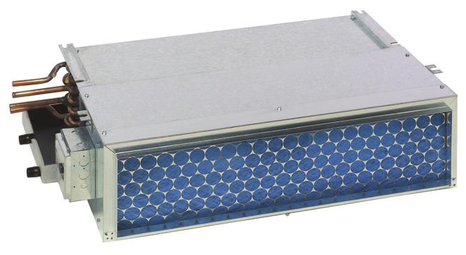
 is our basic model with a galvanized bottom return-air plenum.")
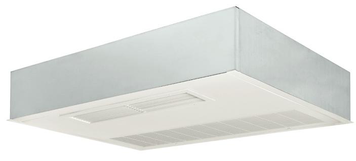
 is designed for horizontal exposed ceiling-mounted applications.")
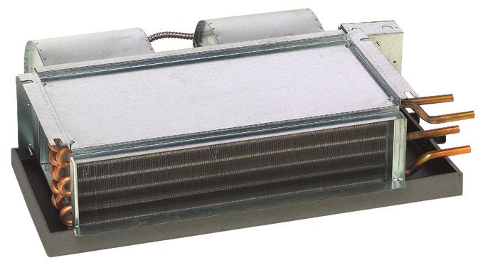
4 Horizontal Models - LH & CFM Horizontal Basic The low profile and flexible design of the Horizontal Basic fan coil (LH-B/low static and HL-B/high static) is ideal for multiple applications. The slim, compact design is well suited for drop-ceiling, closet, hallway and other concealed applications. The Horizontal Basic comes with a powder-coated epoxy drain pan and a wide range of coil, motor and controls options. These models have no exterior cabinet. Horizontal with Return-Air Plenum The Horizontal with Return-Air Plenum (LH-R/low static and HL-R/high static) is our basic model with a galvanized bottom return-air plenum. Ideal for mounting above ceilings, in closets, hallways and bathroom areas, the plenum conceals the unit s blower motor, which is easily accessible for service by removing the bottom panel. Available as a rear return or bottom return. Horizontal Deluxe The Horizontal Deluxe fan coil (LH-D/low static and HL-D/ high static) is designed for horizontal exposed ceiling-mounted applications. The Horizontal Deluxe is our basic unit housed in a cabinet intended for free-blow exposed ceiling mounting. Ideal for remodel situations where adding AC ductwork is limited. Deluxe cabinets are constructed of cold-rolled steel and finished with 385 baked-on tough, soft-white epoxy powder-coated finish. Horizontal Flush The Horizontal Flush (LH-F/low static and HL-F/high static) is a recessed fan coil designed for flush ceiling applications. This unit is designed to accommodate ducted supply air. The telescoping frame and hinged access panel of the Horizontal Flush give it the flexibility to accommodate any type of ceiling. Horizontal Flush Bottom Supply & Return The Horizontal Flush Bottom Supply and Return (LH-E/low static and HL-E/high static) is a recessed fan coil designed for flush ceiling applications. The telescoping frame and hinged access panel of the Horizontal Flush Bottom Supply and Return allow it to fit any type of ceiling. The unit comes in the same attractive, durable powder-coated cabinet as the Horizontal Deluxe. 2 Williams Horizontal Fan Coils 2006 Williams Corporation


5 Features and Benefits Standard Features Heavy-gauge galvanized steel cabinet with neoprene-coated 1/2 thick fiberglass insulation with 3.35 PCF density. Coils are made of 1/2 OD copper tube with aluminum fins (12 FPI) equipped with manual-air vent. DX and steam coils do not include manual-air vent. Coils are 100% underwater pressure tested at 350 PSI with a 300 PSI working pressure. Galvanized drain pan is powder-coated epoxy with a 1/8 thick closed-cell insulation and has primary and secondary drain connections. Three-speed, 115/1/60, 208/1/50-60 or 277/1/60 PSC motor with quick-connect plug. Controls and motors are factory-wired and terminated in a junction box for single-point power supply. One-inch, reinforced duct collar on return- and supply-air openings. Swing-down, hinged return-air grille/access door on Deluxe and Flush models. Deluxe unit has single-deflection supply-air grille. One-inch fiberglass, throwaway filter, except Horizontal Basic. Individually tagged, crated and shipped as scheduled for installation. UL and C-UL approved, ARI certified and 100% factory tested Williams Corporation Williams Horizontal Fan Coils


, washable and metallic.")
6 Equipment Options Options Soft-white, powder-coated epoxy cabinet. Drain Pans - stainless steel and double-wall. Insulation - fiberglass, foil-face, elastomeric and double-wall (solid or perforated) in 1/2 and 1 thicknesses. Coils - copper fins/tubes, stainless steel fins/tubes, phenolic coated, stainless steel end plates. All options are available on one- to six-rows. Systems - two- or four-pipe, hydronic cooling/ heating, steam, direct-expansion (DX) and/or electric heat. Cabinet - Deluxe, Flush and custom colors. Controls - unlimited selection of factory-mounted valves and controls. Filters - two-inch thick throwaway (except Horizontal Basic), washable and metallic. Flow-control circulator for water heating applications. Grilles available as double-deflection and in custom colors. Electric Strip Heat from 0.5 to 5 kw. 4 Williams Horizontal Fan Coils 2006 Williams Corporation
7 ARI Cooling Capacity ARI Certified Cooling Capacity Williams LH (Low Static) & HL (High Static) Series horizontal fan coils have been rated in accordance with ARI Standard for room fan-coils air-conditioners and are certified by the Air-Conditioning and Refrigeration Institute to meet the following product performance ratings: ARI APPROVED STANDARD RATINGS MODEL / SIZE MOTOR / TYPE STYLE RATED CFM GPM WPD (FT./H2O) COOLING CAPACITY TOTAL COOLING (BTUH) SENSIBLE COOLING (BTUH) POWER INPUT (WATTS) Notes: (High Static) (High Static) (High Static) (High Static) (High Static) (High Static) B ,530 5, R, Q ,240 4, D, E, F ,650 4, B ,680 6, R, Q ,250 5, D, E, F ,750 5, B ,680 6, R, Q ,390 5, D, E, F ,960 5, B ,920 8, R, Q ,760 8, D, E, F ,280 7, B ,470 10, R, Q ,900 9, D, E, F ,500 9, B ,510 12, R, Q ,200 11, D, E, F ,890 11, B ,790 14, R, Q ,140 13, D, E, F ,390 13, B ,640 19, R, Q ,130 18, D, E, F ,450 18, B ,900 19, R, Q ,300 19, D, E, F ,620 18, B 1, ,130 23, R, Q 1, ,610 22, D, E, F ,070 22, B 1, ,830 23, R, Q 1, ,960 23, D, E, F 1, ,430 22, B 1, ,210 26, R, Q 1, ,500 27, D, E, F 1, ,390 26, B 1, ,480 28, R, Q 1, ,600 26, D, E, F 1, ,520 25, ) Based on 80 F DB and 67 F WB EAT, 45 F EWT, 10 F temperature rise, high fan speed. Motor voltage 115/1/60 power source. Air flow under dry coil conditions. Water pressure drops shown in feet of water. All units are listed under UL Category Control No. LZFE. 2) Ratings are based on actual CFM. Standard coils for is 3 rows and is 4 rows. 3) Legend - B = Basic; R = Rear return-air plenum; Q = Bottom return-air plenum; D = Deluxe; E = Bottom supply and bottom return and F = Flush Williams Corporation Williams Horizontal Fan Coils
8 Heating Performance / Coil Data Heating Performance Heating Performance MODEL / SIZE MOTOR / TYPE COIL ROWS/ (FPI) RATED CFM MBH GPM WPD (FT./H2O) (High Static) (High Static) (High Static) (High Static) (High Static) (High Static) 1 Row (12) Rows (12) Row (12) Rows (12) Row (12) Rows (12) Row (12) Rows (12) Row (12) Rows (12) Row (12) Rows (12) Row (12) Rows (12) Row (12) Rows (12) Row (12) Rows (12) Row (12) 1, Rows (12) 1, Row (12) 1, Rows (12) 1, Row (12) 1, Rows (12) 1, Row (12) 1, Rows (12) 1, Notes: Based on 70 F DB EAT, 180 F EWT, 40 F temperature drop, high fan speed. Motor voltage 115/1/60 power source. Air flow under dry coil conditions. Water pressure drops shown in feet of water. Coil Data Coils are made from ½ O.D. copper tubing with.017 wall thickness, and tubes are staggered for maximum heat transfer. A manual air vent is standard on all hydronic coils. DX and steam coils do not include manual-air vent. All coils are 100% underwater pressure tested to 350 PSIG with a 300 PSIG working pressure. Steam coils are rated for up to 15 PSIG or 250ºF. Coils are available in two- or four-pipe, and from one- to six-row configurations for LH & units with any combination of chilled or hot water, steam or direct expansion. Custom circuiting is available. 6 Williams Horizontal Fan Coils 2006 Williams Corporation
9 Electric Heat Coil Rows Single-Row Coil Two-Row Coil Three-Row Coil Four-Row Coil Five-Row Coil *Six-Row Coil * Five-row coil maximum when selecting a DX coil with a hot water coil.* S T A N D A R D O P T I O N A L Coil Options: DX Includes distributor and nozzle, TXV must be field furnished and installed Steam 1-15 PSIG Opposite End Connection (E). Place the E - pipe-hand connection in the eleventh digit of the model number - when ordering Preheat Coil Position (PREHEAT) Standard coil is reheat position Phenolic Anti-Corrosion Coating (PAC) Stainless Steel Tubes/Fins/End Plates Copper Fins/Tubes/End Plates 6-16 Fins Per Inch (Standard is 12 FPI) Coil connections on the chilled water side for is ½ and ¾ on The hot water connection is ½ on the Electric Heat Electric heat may be furnished with either hydronic, direct expansion or steam coils and is factory-mounted, wired, and tested. Option-equipped with low-watt density (for long life) nichrome wire elements. The heater has a built-in, high limit, and fusible link to provide maximum safety. Model / Size 002 (Low Static Only) kw Voltage AMPS Williams Corporation Williams Horizontal Fan Coils
10 Air Flow Data Air Flow Data Air flow shown below is under dry coil conditions. SIZE 002 Free Return 002 w/plenum 003 Free Return 003 w/plenum 004 Free Return 004 w/plenum 006 Free Return 006 w/plenum 008 Free Return 008 w/plenum 010 Free Return 010 w/plenum 012 Free Return 012 w/plenum Notes: AIR FLOW DATA MODEL / STYLE (Hi-Static) (Hi-Static) (Hi-Static) (Hi-Static) (Hi-Static) (Hi-Static) COIL ROWS EXTERNAL STATIC PRESSURE HI MED LOW HI MED LOW HI MED LOW HI MED LOW HI MED LOW HI MED LOW 3 ROW ROW ROW ROW ROW ROW ROW ROW ROW ROW ROW ROW ROW ROW ROW ROW ROW ROW ROW ROW ROW ROW ROW ROW ROW ROW ROW ROW ROW ROW ROW ROW ROW ROW ROW ROW ROW ROW ROW ROW Ratings and capacity tables based on nominal CFM. 8 Williams Horizontal Fan Coils 2006 Williams Corporation
11 Motor Data Motor Data Motors are wired to a junction box ready for single-point field connection. Outstanding motor features: Quick-Connect Plug Permanent Split Capacitor Thermal overload protection 1050 RPM for lower operating costs Oversized bearings and permanently lubricated and sealed 122ºF maximum operating temperature rise Custom motor mounts designed to reduce noise and eliminate vibration Stators are epoxy-dipped for more efficient motor cooling Optional motors: 208V-1Ø-60 motors 230/220V-1Ø-60 motors 277V-1Ø-60 motors 50-Hz motors in specified voltages 60 Hertz Single-Phase Voltage/Watts Motors (1100 RPM) 115V 208V 230V 277V Model Motor Type HP (Qty) Blowers AMPS WATTS AMPS WATTS AMPS WATTS AMPS WATTS 002 1/20 (1) /20 (1) 1/15 (1) 1/15 (1) 1/4 (1) 1/4 (1) 1/4 (1) (High Static) (High Static) (High Static) (High Static) (High Static) (High Static) 1/10 (1) 1/8 (1) 1/8 (1) 1/4 (1) 1/4 (1) 1/4 (1) Notes: Motor full load amps listed refer to NEC amps. Actual motor nameplate amps may vary Williams Corporation Williams Horizontal Fan Coils
12 Sound Data Sound Data Notes: Model / Fan Size Speed OCTAVE BAND CENTER FREQUENCY (CPS) High Medium Low High Medium Low High Medium Low High Medium Low High Medium Low High Medium Low High Medium Low ) Power levels are in db RE watts. 2) Sound data tested in accordance with ASHRAE Standard 68 and ARI Standard 260 and ) Ratings are based on actual CFM. Standard coils for is 3 rows and is 4 rows. 4) Air Flow under dry coil conditions. 10 Williams Horizontal Fan Coils 2006 Williams Corporation
13 Certified Dimensional Drawings - LH & HORIZONTAL BASIC CFM Right-hand unit shown, left-hand unit opposite. Coil connections determined by facing the supply-air opening. Electrical junction box is located on the same side as the coil connections. Unit must be installed level and condensate drain lines should be trapped. Drain pan is powder-coated epoxy with a 1/8 thick closed-cell insulation and has 3/4 NPT primary and secondary drain connections. Entire cabinet, scroll and blower wheel are heavy-gauge, galvanized steel. Coil Connections: 1/2 CW and HW on Williams Corporation Williams Horizontal Fan Coils
14 Certified Dimensional Drawings - LH & HORIZONTAL BASIC CFM MODEL BASIC A B C D E F G /2 21-3/ /8 9-1/ /2 21-3/ /8 9-1/ /2 22-1/4 10-3/8 7-1/ /8 10-5/ /2 22-1/4 10-3/8 7-1/ /8 10-5/ /2 22-1/4 10-3/8 7-1/ /8 10-5/8 12 All sizes shown in inches. Right-hand unit shown, left-hand unit opposite. Coil connections determined by facing the supply-air opening. Electrical junction box is located on the same side as the coil connections. Unit must be installed level and condensate drain lines should be trapped. Drain pan is powder-coated epoxy with a 1/8 thick closed-cell insulation and has 3/4 NPT primary and secondary drain connections. Entire cabinet, scroll and blower wheel are heavy-gauge, galvanized steel. Coil Connections: 1/2 CW on , 3/4 CW on and 1/2 HW on Williams Horizontal Fan Coils 2006 Williams Corporation
15 Certified Dimensional Drawings - LH & HORIZONTAL REAR RETURN-AIR PLENUM CFM Right-hand unit shown, left-hand unit opposite. Coil connections determined by facing the supply-air opening. Electrical junction box is located on the same side as the coil connections. Unit must be installed level and condensate drain lines should be trapped. Drain pan is powder-coated epoxy with a 1/8 thick closed-cell insulation and has 3/4 NPT primary and secondary drain connections. Entire cabinet, scroll and blower wheel are heavy-gauge, galvanized steel. Coil Connections: 1/2 CW and HW on Williams Corporation Williams Horizontal Fan Coils
16 Certified Dimensional Drawings - LH & HORIZONTAL REAR RETURN-AIR PLENUM CFM MODEL FILTER REAR RETURN-AIR A B C D E F G H J K L M N SIZE /2 26-7/ / / /4 11-1/4 10X28X /2 32-7/ / / /4 11-1/4 10X34X /2 32-7/ / /8 7-13/ / /4 13-1/4 12X34X /2 38-7/ / /8 7-13/ / /4 13-1/4 12X40X /2 44-7/ / /8 7-13/ / /4 13-1/4 12X46X1 14 All sizes shown in inches. Right-hand unit shown, left-hand unit opposite. Coil connections determined by facing the supply-air opening. Electrical junction box is located on the same side as the coil connections. Unit must be installed level and condensate drain lines should be trapped. Drain pan is powder-coated epoxy with a 1/8 thick closed-cell insulation and has 3/4 NPT primary and secondary drain connections. Entire cabinet, scroll and blower wheel are heavy-gauge, galvanized steel. Coil Connections: 1/2 CW on , 3/4 CW on and 1/2 HW on Williams Horizontal Fan Coils 2006 Williams Corporation
17 Certified Dimensional Drawings - LH & HORIZONTAL BOTTOM RETURN-AIR PLENUM CFM Right-hand unit shown, left-hand unit opposite. Coil connections determined by facing the supply-air opening. Electrical junction box is located on the same side as the coil connections. Unit must be installed level and condensate drain lines should be trapped. Drain pan is powder-coated epoxy with a 1/8 thick closed-cell insulation and has 3/4 NPT primary and secondary drain connections. Entire cabinet, scroll and blower wheel are heavy-gauge, galvanized steel. Coil Connections: 1/2 CW and HW on Williams Corporation Williams Horizontal Fan Coils
18 Certified Dimensional Drawings - LH & HORIZONTAL BOTTOM RETURN-AIR PLENUM CFM MODEL FILTER BOTTOM RETURN-AIR A B C D E F G H J K L M N SIZE /2 26-7/ / / /4 11-1/4 10X28X /2 32-7/ / / /4 11-1/4 10X34X /2 32-7/ / /8 7-13/ / /4 13-1/4 12X34X /2 38-7/ / /8 7-13/ / /4 13-1/4 12X40X /2 44-7/ / /8 7-13/ / /4 13-1/4 12X46X1 16 All sizes shown in inches. Right-hand unit shown, left-hand unit opposite. Coil connections determined by facing the supply-air opening. Electrical junction box is located on the same side as the coil connections. Unit must be installed level and condensate drain lines should be trapped. Drain pan is powder-coated epoxy with a 1/8 thick closed-cell insulation and has 3/4 NPT primary and secondary drain connections. Entire cabinet, scroll and blower wheel are heavy-gauge, galvanized steel. Coil Connections: 1/2 CW on , 3/4 on and 1/2 HW on Williams Horizontal Fan Coils 2006 Williams Corporation
19 Certified Dimensional Drawings - LH & HORIZONTAL DELUXE CFM Right-hand unit shown, left-hand unit opposite. Coil connections determined by facing the supply-air opening. Electrical junction box is located on the same side as the coil connections. Unit must be installed level and condensate drain lines should be trapped. Drain pan is powder-coated epoxy with a 1/8 thick closed-cell insulation and has 3/4 NPT primary and secondary drain connections. Entire cabinet, scroll and blower wheel are heavy-gauge, galvanized steel. Coil Connections: 1/2 CW and HW on Williams Corporation Williams Horizontal Fan Coils
20 Certified Dimensional Drawings - LH & HORIZONTAL DELUXE CFM MODEL FILTER DELUXE A B C D E F G H SIZE / /8 6-1/4 24-3/4 (2) 11X / /8 6-1/4 30-3/4 (2) 11X / /8 7-3/4 30-3/4 (2) 11X / /8 7-3/4 36-3/4 (2) 11X / /8 7-3/4 42-3/4 (2) 11X27 18 All sizes shown in inches. Right-hand unit shown, left-hand unit opposite. Coil connections determined by facing the supply-air opening. Electrical junction box is located on the same side as the coil connections. Unit must be installed level and condensate drain lines should be trapped. Drain pan is powder-coated epoxy with a 1/8 thick closed-cell insulation and has 3/4 NPT primary and secondary drain connections. Entire cabinet, scroll and blower wheel are heavy-gauge, galvanized steel. Coil Connections: 1/2 CW on , 3/4 CW on and 1/2 HW on Williams Horizontal Fan Coils 2006 Williams Corporation
21 Certified Dimensional Drawings - LH & HORIZONTAL FLUSH CFM Right-hand unit shown, left-hand unit opposite. Coil connections determined by facing the supply-air opening. Electrical junction box is located on the same side as the coil connections. Unit must be installed level and condensate drain lines should be trapped. Drain pan is powder-coated epoxy with a 1/8 thick closed-cell insulation and has 3/4 NPT primary and secondary drain connections. Entire cabinet, scroll and blower wheel are heavy-gauge, galvanized steel. Coil Connections: 1/2 CW and HW on Williams Corporation Williams Horizontal Fan Coils
22 Certified Dimensional Drawings - LH & HORIZONTAL FLUSH CFM MODEL FILTER FLUSH A B C D E F G H J SIZE / /8 25-1/8 27-3/4 47-1/2 44-3/8 25-1/8 (2) 11X / /8 31-1/8 27-3/4 55-1/2 52-1/2 25-1/8 (2) 11X / /8 31-1/8 27-3/4 55-1/2 52-1/2 25-1/8 (2) 11X / /8 37-1/8 27-3/4 61-1/2 58-3/8 25-1/8 (2) 11X / /8 43-1/8 27-3/4 61-1/2 58-3/8 25-1/8 (2) 11X27 20 All sizes shown in inches. Right-hand unit shown, left-hand unit opposite. Coil connections determined by facing the supply-air opening. Electrical junction box is located on the same side as the coil connections. Unit must be installed level and condensate drain lines should be trapped. Drain pan is powder-coated epoxy with a 1/8 thick closed-cell insulation and has 3/4 NPT primary and secondary drain connections. Entire cabinet, scroll and blower wheel are heavy-gauge, galvanized steel. Coil Connections: 1/2 CW on , 3/4 CW on and 1/2 HW on Williams Horizontal Fan Coils 2006 Williams Corporation
23 Certified Dimensional Drawings - LH & HORIZONTAL FLUSH BOTTOM RETURN AND SUPPLY CFM Right-hand unit shown, left-hand unit opposite. Coil connections determined by facing the supply-air opening. Electrical junction box is located on the same side as the coil connections. Unit must be installed level and condensate drain lines should be trapped. Drain pan is powder-coated epoxy with a 1/8 thick closed-cell insulation and has 3/4 NPT primary and secondary drain connections. Entire cabinet, scroll and blower wheel are heavy-gauge, galvanized steel. Coil Connections: 1/2 CW and HW on Williams Corporation Williams Horizontal Fan Coils
24 Certified Dimensional Drawings - LH & HORIZONTAL FLUSH BOTTOM RETURN AND SUPPLY CFM MODEL FLUSH BOTTOM / RETURN & SUPPLY A B C D E F G H FILTER SIZE / /8 47-3/8 44-1/4 37-1/ X / /8 55-3/8 52-1/4 37-1/ X / /8 55-3/8 52-1/4 43-1/ X / /8 61-3/8 58-1/4 43-1/ X / /8 61-3/8 58-1/4 43-1/ X25 22 All sizes shown in inches. Right-hand unit shown, left-hand unit opposite. Coil connections determined by facing the supply-air opening. Electrical junction box is located on the same side as the coil connections. Unit must be installed level and condensate drain lines should be trapped. Drain pan is powder-coated epoxy with a 1/8 thick closed-cell insulation and has 3/4 NPT primary and secondary drain connections. Entire cabinet, scroll and blower wheel are heavy-gauge, galvanized steel. Coil Connections: 1/2 CW on , 3/4 CW on and 1/2 HW on Williams Horizontal Fan Coils 2006 Williams Corporation
25 Weights and Measures Weights and Measures The following LH & weights and measures are based on fan coil units only. Add approximately 20% for packaging and crating. Dimensions / Inches Weight/lbs. Dimensions / Millimeters Weight/kg Unit Model Rows Height Width Depth Dry Wet Height Width Depth Dry Wet LH & Basic LH & Return-Air Plenum LH & Deluxe LH & Flush Williams Corporation Williams Horizontal Fan Coils
26 Guide Specifications General Furnish and install Williams Horizontal Direct Drive Fan Coil units as indicated on the plans and in the specifications. All units shall be completely factory-assembled, tested and shipped as one working unit. All units shall be capable of meeting or exceeding the scheduled capacities for cooling, heating and air delivery. Dimensions for each model and size shall be considered maximums. Units shall be UL listed and also in compliance with UL/ANSI Standard 1995, and be certified as complying with the latest edition of ARI Standard 440. Construction All unit chassis shall be fabricated of heavy gauge galvanized steel panels able to meet 125-hour salt spray test per ASTM B-117. All exterior panels shall be insulated with 1/2 thick, 3.35 pound per cubic foot, dual density fiberglass insulation rated for a maximum air velocity of 3600 f.p.m. Insulation shall conform to UL 181 for erosion and NFPA 90A and 90B for flame spread (25) and smoke developed (50) rating per ASTM E-84 and UL 723 and CAN./ULC, S102-M88. All concealed units shall have a minimum 1 duct collar on the discharge. Plenum units shall have a minimum 1 duct collar on the return. All exposed units shall have exterior panels fabricated of cold-rolled steel. The fan and filter bottom access panel has two screws for easy removal and access for service and is also equipped with a safety chain. OPTION: Provide foil-faced insulation in lieu of standard. Foil insulation shall meet or exceed the requirements stated above, and in addition, meet ASTM Standards C665 and C-1136 for biological growth in insulation. Insulation shall be lined with aluminum foil, fiberglass scrim reinforcement, and 30-pound kraft paper laminated together with a flame resistant adhesive. All exposed edges shall be sealed to prevent any fibers from reaching the air stream. OPTION: Provide Elastomeric Closed Cell Foam Insulation in lieu of standard. Insulation shall conform to UL 181 for erosion and NFPA 90A for fire, smoke and melting, and comply with a 25/50 Flame Spread and Smoke Developed Index per ASTM E- 84 or UL 723. Additionally, insulation shall comply with Anti-microbial Performance Rating of zero, no observed growth, per ASTM G21. Polyethylene insulation is not acceptable. Unit mounting shall be by hanger and slotted hanging brackets provided at four locations. For easy installation, exposed units provided with 1/2 mounting knockouts in four places. Painted Finish All exposed cabinet exterior panels shall be provided with soft-white powder-coated epoxy finish. Sound Units shall have published sound power level data tested in accordance with ARI Standard (non-ducted equipment) and ARI Standard (ducted equipment). Fan Assembly Unit fan shall be a dynamically balanced, forwardly curved, DWDI centrifugal type constructed of heavy gauge zinc coated galvanized steel for corrosion resistance. Motors shall be high efficiency, permanently lubricated sleeve bearing, permanent split-capacitor type with UL and C-UL listed automatic reset thermal overload protection and three separate horsepower taps. Single speed motors are not acceptable. 24 Williams Horizontal Fan Coils 2006 Williams Corporation
27 Guide Specifications The fan assembly shall be easily removable for servicing the motor and blower at or away from the unit. The entire fan assembly shall be able to come out of the unit by removing two wing nuts and unplugging the motor. Plenum unit fan assemblies shall be easily serviced through an access panel provided. OPTION: Devices used to energize and de-energize (switch) fan speeds must be totally silent. Mercury and/or quiet relays and/or contactors are not acceptable. Coils All cooling and heating coils shall optimize rows and fins per inch to meet the specified capacity. Coils shall have seamless copper tubes and shall be mechanically expanded to provide an efficient, permanent bond between the tube and fin. Fins shall have high efficiency aluminum surface optimized for heat transfer, air pressure drop and carryover. All coils shall be hydrostatically tested at 350 PSIG air pressure under water, and rated for a maximum of 300 PSIG working pressure at 180 F maximum water temperature. Direct expansion cooling coils shall include a fixed orifice distributor and nozzle. Steam coils shall be standard steam type suitable for temperatures above 35 F and 15 PSIG maximum working pressure. OPTION: Coil casing shall be fabricated from 304 Stainless Steel. All coils shall be provided with a manual-air vent fitting to allow for coil venting. OPTION: Provide automatic air vents in lieu of manual-air vents. Cooling and heating coils shall be in the common coil casing, heating coils shall be furnished in the re-heat or pre-heat position on the unit with chilled water coils, and DX coil shall be in pre-heat position only. Drain Pans Primary condensate drain pans shall be single wall, heavy gauge, powder-coated epoxy and extend under the entire cooling coil. Drain pans shall be of one-piece construction and be positively sloped for condensate removal. Drain pans shall have primary and secondary drain connections. The drain pan shall be externally insulated with a closed cell foam insulation. The insulation shall carry no more than a 25/50 Flame Spread and Smoke Developed Rating per ASTM E-84 and UL 723 and fungi resistant per ASTM G21/C1338, bacteria resistant per ASTM G22 and mold growth per UL 181. OPTION: Provide a single wall primary drain pan constructed entirely of heavy gauge type 304 stainless steel for superior corrosion resistance. Stainless steel drain pans shall be externally insulated and meet or exceed the requirements stated above. Filters All plenum and exposed units shall be furnished with a minimum 1 nominal glass fiber throwaway filter. Filters shall be tight fitting to prevent air bypass. Plenum and exposed unit filters shall be easily removable from the bottom or rear of the unit without the need for tools. OPTION: Provide unit with 1 pleated filters rated at 25-30% efficiency and MERV 6 based on ASHRAE Williams Corporation Williams Horizontal Fan Coils
28 Guide Specifications Electrical Units shall be furnished with single point power connection. Provide an electrical junction box with terminal strip for motor and other electrical terminations. OPTION: The factory-mounted terminal wiring strip consists of a multiple position screw terminal block to facilitate wiring terminations for the electric control valves and thermostats. Electric Heat Furnish an electric resistance heating assembly as an integral part of the fan coil unit, with the heating capacity, voltage and kilowatts scheduled. The heater assembly shall be designed and rated for installation on the fan coil unit without the use of duct extensions or transitions, and be located in the unit as to not expose the fan assembly to excessive leaving air temperatures that could affect motor performance. The heater and unit assembly shall be listed for zero clearance and meet all NEC requirements, and be UL listed with the unit as an assembly in compliance with UL/ANSI Standard All heating elements shall be open coil type Nichrome wire mounted in ceramic insulators and located in an insulated heavy gauge galvanized steel housing. All elements shall terminate in a machine staked stainless steel terminal secured with stainless steel hardware for corrosion resistance. The element support brackets shall be spaced no greater than 3-1/2 on center. All internal wiring shall be rated for 90 C minimum. An incoming line power distribution block shall be provided and designated to accept single point power wiring capable of carrying 125% of the calculated load current. OPTION: Devices used to energize and de-energize (switch) electric heat must be totally silent. Mercury and/or quiet relays and/or contactors are not acceptable. Piping Packages (Option) Provide a factory assembled valve piping package to consist of a 2 or 3 way, on/off, motorized electric control valve and two ball isolation valves. Control valves are piped normally closed to the coil. Maximum entering water temperature on the control valve is 180 F, and maximum close-off pressure is 75 PSIG (1/2 ) or 50 PSIG (3/4 ). Maximum operating pressure shall be 300 PSIG. OPTION: Provide 3-wire floating point modulat-ing control valve in lieu of standard 2-position control valve with factory assembled valve piping package. OPTION: Provide either a fixed or adjustable flow control device for each piping package. OPTION: Provide pressure-temperature ports for each piping package. Piping packages are shipped installed on all units and can be shipped separately by request only. All heaters shall include over temperature protection consisting of an automatic reset primary thermal limit and back up secondary thermal limit. All heaters shall be single stage. 26 Williams Horizontal Fan Coils 2006 Williams Corporation
29 THIS PAGE INTENTIONALLY LEFT BLANK Williams Corporation Williams Horizontal Fan Coils
30 THIS PAGE INTENTIONALLY LEFT BLANK 28 Williams Horizontal Fan Coils 2006 Williams Corporation
31
32 APPLIED PRODUCTS GROUP 510 E. Memorial Rd., Suite C-4 Oklahoma City, OK Fax: CORPORATE OFFICE 250 W. Laurel Street Colton, CA Fax: williamscomfortprod.com 2006 Williams Furnace Company, Inc. WA
Vertical Stack Fan Coils 300-1,200 CFM
 Vertical Stack Fan Coils 300-1,200 CFM Table of Contents Williams Fan Coils & Air Handlers... 1 Vertical Stack Models... 2 Features & Benefits... 4 Equipment Options... 5 ARI Cooling Capacity... 6 Heating
RAH Engineering Guide
 FAN COIL UNITS FREE RETURN RAH Engineering Guide SO TOUGH, WE GUARANTEE IT. RAHC RAHO RAHR www.superiorrex.com Table of Contents Features and Benefits... 3 Construction Features... 4 Standard and Optional
FCVC Series VERTICAL FAN COILS
 VERTICAL FAN COILS The FCVC is designed for concealed, wall mounted installations with flexible heating/ cooling loads and minimal duct requirements. With a variety of options, such as fiber free insulation,
SBH / SBV Sales Guide BLOWER-COILS HORIZONTAL AND VERTICAL
 SO TOUGH, WE GUARANTEE IT. SBH / SBV Sales Guide BLOWER-COILS HORIZONTAL AND VERTICAL SBH SBV www.superiorrex.com SO TOUGH, WE GUARANTEE IT! www.superiorrex.com SBH / SBV Series: CONSTRUCTION FEATURES
Submittal. Front View Side View
 RBHO Horizontal Low Profile Concealed Free Return Submittal FCU-RBHO-1.0 07-25-18 Top View (Drain Pan Omitted) Bottom View Front View Side View Left hand unit shown. All dimensions are inches [millimeters].
Product Data. Features/Benefits. 42BH System Fan Coil. 800 to 4000 Cfm
 Product Data 42BH System Fan Coil 800 to 4000 Cfm Satisfy All Your Design Requirements with Carrier s Versatile 42BH Fan Coil Unit A selection of 6 sizes covers capacities from 800 to 4000 cfm Choice of
The Premium Quality Fan Coil Units for Horizontal Application Hydronic or Electric Heat
 Producing Quality Heating & Cooling Equipment For Over 50 Years CEA SERIES CEILING EPOSED HORIZONTAL FAN COIL UNITS The Premium Quality Fan Coil Units for Horizontal Application Hydronic or Electric Heat
Submittal DIMENSIONS SIZE FAN SIZE L W H C D E F G J K [406] [508] 25 [635] [406] 16 [406] 16 [406] 39-1/2 [1003] 44-1/2 [1130] 51 [1295] 59 [1499]
![Submittal DIMENSIONS SIZE FAN SIZE L W H C D E F G J K [406] [508] 25 [635] [406] 16 [406] 16 [406] 39-1/2 [1003] 44-1/2 [1130] 51 [1295] 59 [1499]](/thumbs/94/122284584.jpg "Submittal DIMENSIONS SIZE FAN SIZE L W H C D E F G J K [406] [508] 25 [635] [406] 16 [406] 16 [406] 39-1/2 [1003] 44-1/2 [1130] 51 [1295] 59 [1499]") BC--1.0 03-01-1 Belt Drive Blower Coil Unit, Basic Unit Discharge ARGT. 1 4. See page 1 for filter rack details. 5. Base rail is optional on he base unit. See page 13. Base rails must be used with mixing
BC--1.0 03-01-1 Belt Drive Blower Coil Unit, Basic Unit Discharge ARGT. 1 4. See page 1 for filter rack details. 5. Base rail is optional on he base unit. See page 13. Base rails must be used with mixing
Complete HVAC Capability
 Air Handling Units Brochure 1110 January 2006 Complete HVAC Capability MEA Horizontal Draw-Thru to Size 65 Vertical Draw-Thru to Size 50 1000 to 60,000 CFM Forward Curved or Airfoil Wheels Inlet Vane Option
RAV Sales Guide FAN COIL UNITS HI-RISE, VERTICAL
 RAV Sales Guide FAN COIL UNITS HI-RISE, VERTICAL RAVS RARM RARS RAVE RAVM RAVL RARP RISER www.superiorrex.com RAV Series: VERTICAL HI-RISE CONCEALED SO TOUGH, WE GUARANTEE IT! www.superiorrex.com Model
FS Fan-Coil Units Hi-Rise, Vertical
 FS Fan-Coil Units Hi-Rise, Vertical FSC Concealed Dimensional Data 4-PIPE 2-PIPE TOP VIEWS Page Trims Short (5/8") Here! SIDE VIEW FRONT VIEW Dimensions Unit Size A B Single/Double Supply C D E 03 & 04
48CWA2-00 Chilled Water Fan Coil With or Without Electric Heat 2-Pipe Heat / Cool Fan Coil 48,000 BTUH
 48CWA2-00 Chilled Water Fan Coil With or Without Electric Heat 2-Pipe Heat / Cool Fan Coil 48,000 BTUH Rev. 1.3 HVAC Guide Specifications Chilled or Hot Water with Optional Electric Heat Multi-Position
36CWA4-HW 4-Pipe Chilled & Hot Water Air Handler (120V) 4-Pipe Heat & Cool Fan Coil 36,000 BTUH
 4-Pipe Heat & Cool Fan Coil 36,000 BTUH") 36CWA4-HW 4-Pipe Chilled & Hot Air Handler (120V) 4-Pipe Heat & Cool Fan Coil 36,000 BTUH Rev. 1.2 HVAC Guide Specifications Chilled & Hot Multi-Position Fan Coil 4-Pipe Nominal Size: 36,000 BTUH Multiaqua
36CWA4-HW 4-Pipe Chilled & Hot Air Handler (120V) 4-Pipe Heat & Cool Fan Coil 36,000 BTUH Rev. 1.2 HVAC Guide Specifications Chilled & Hot Multi-Position Fan Coil 4-Pipe Nominal Size: 36,000 BTUH Multiaqua
24CWA4-HW 4-Pipe Chilled & Hot Water Air Handler (120V)
") 24CWA4-HW 4-Pipe Chilled & Hot Air Handler (120V) 4-Pipe Heat & Cool Fan Coil 24,000 BTUH Rev. 1.2 HVAC Guide Specifications Chilled & Hot Multi-Position Fan Coil 4-Pipe Nominal Size: 24,000 BTUH Multiaqua
24CWA4-HW 4-Pipe Chilled & Hot Air Handler (120V) 4-Pipe Heat & Cool Fan Coil 24,000 BTUH Rev. 1.2 HVAC Guide Specifications Chilled & Hot Multi-Position Fan Coil 4-Pipe Nominal Size: 24,000 BTUH Multiaqua
Submittal 30 [762] 36 [914] 40 [1016] 50 [1270] 60 [1524] 70 [1778]
![Submittal 30 [762] 36 [914] 40 [1016] 50 [1270] 60 [1524] 70 [1778]](/thumbs/85/92244975.jpg "Submittal 30 [762] 36 [914] 40 [1016] 50 [1270] 60 [1524] 70 [1778]") FCU-THBP-1.0 08-22-18 THBP Horizontal Low Profile Plenum Return Top View (Drain Pan Omitted) Bottom View Front View Left hand unit shown. All dimensions are inches [millimeters]. Side View Unit Size A
FCU-THBP-1.0 08-22-18 THBP Horizontal Low Profile Plenum Return Top View (Drain Pan Omitted) Bottom View Front View Left hand unit shown. All dimensions are inches [millimeters]. Side View Unit Size A
FN Fan-Coil Units High-Performance, Horizontal
 FN Fan-Coil Units High-Performance, Horizontal Model FNX Exposed-Cabinet Dimensional Data Notes: 1. All dimensions are in inches [mm] and are +/- 1/8" [3 mm]. Metric values are soft conversions. 2. See
HBC SERIES-PSC MOTOR HBCX SERIES-ECM MOTOR
 PRODUCT SPECIFICATIONS *HBC(X) *PHBC(X) *RHBC(X) *CHBC(X) Chilled Water/Hot Water 2-pipe/4-Pipe HBC SERIES- HBCX SERIES-ECM MOTOR Ceiling Concealed Horizontal -1 CFM Ceiling Concealed Ceiling Recessed
Horizontal and Vertical BELT DRIVE AIR HANDLING UNITS
 Horizontal and Vertical BELT DRIVE AIR HANDLING UNITS TABLE OF CONTENTS H & V Features and Benefits...4 Coil and Filter Data, Static Pressure Data...7 Electric Resistance Heat Section...8 Coil Information
HBC SERIES-PSC MOTOR HBCX SERIES-ECM MOTOR
 PRODUCT SPECIFICATIONS *HBC(X) *PHBC(X) *RHBC(X) *CHBC(X) Chilled Water/Hot Water 2-pipe/4-Pipe HBC SERIES- HBCX SERIES-ECM MOTOR Ceiling Concealed Horizontal -1 CFM Ceiling Concealed Ceiling Recessed
TVS/R FAN COIL UNITS HI-RISE, VERTICAL
 TVS/R FAN COIL UNITS HI-RISE, VERTICAL TVRM TVRP Riser TVRS TVSE TVSM TVSR TVSS Redefine your comfort zone. www.titus-hvac.com Redefine your comfort zone www.titus-hvac.com Model TVS/R: CONCEALED, HI-RISE
Product Data. 42D Ducted Fan Coil Air Conditioners cfm
 Product Data 42D Ducted Fan Coil Air Conditioners 600-2000 cfm Carrier s 42D series ducted fan coil units offer design and equipment location flexibility Choice of 5 models, each available in 8 sizes For
RBV Sales Guide FAN COIL UNITS FLOOR-MOUNTED, VERTICAL
 RBV Sales Guide FAN COIL UNITS FLOOR-MOUNTED, VERTICAL RBVS RBVR RBVC www.superiorrex.com RBV Series: LOW POWER CONSUMPTION, ACCESSIBLE AND FLEXIBLE Owners Owners can choose between a standard or elevated
Hi-Performance Series Fan Coil Technical Catalog
 Hi-Performance Series Fan Coil Technical Catalog HYB Horizontal Hideaway Furred-in with galvanized finish for ducted/high static applications in drop-ceilings or over-closets. (600-2000 CFM) HGC Horizontal
BVX SERIES VERTICAL DIRECT EXPANSION BLOWER COIL UNITS
 BVX SERIES VERTICAL DIRECT EXPANSION BLOWER COIL UNITS MAGIC AIRE BVX SERIES FAN COILS ARE ETLC LISTED IN ACCORDANCE WITH UL 1995 AND ARE ASSEMBLED TO ORDER FOR COMPETITIVE DELIVERY. UNITED ELECTRIC COMPANY,
VERTICAL SINGLE AND DOUBLE WALL BELT DRIVE AIR HANDLER DX OR CHILLED WATER COOLING WITH HOT WATER OR ELECTRIC HEAT
 VERTICAL SINGLE AND DOUBLE WALL BELT DRIVE AIR HANDLER DX OR CHILLED WATER COOLING WITH HOT WATER OR ELECTRIC HEAT SIZES FROM 600 TO 4,000 All Technical Specifications are Subject to Change without Notice.
MHWW-24-H-1 Chilled/Hot Water Hi-Wall Fan Coil. Heat / Cool Fan Coil 24,000 BTUH. Rev. 1.3
 MHWW-24-H-1 Chilled/Hot Water Hi-Wall Fan Coil Heat / Cool Fan Coil 24,000 BTUH Rev. 1.3 HVAC Guide Specifications Chilled and Hot Water Hi-Wall Fan Coil 2-Pipe Nominal Size: 24,000 BTUH Multiaqua Model
MODULAR SINGLE AND DOUBLE WALL BELT DRIVE AIR HANDLER DX OR CHILLED WATER COOLING HOT WATER OR ELECTRIC HEATING
 MODULAR SINGLE AND DOUBLE WALL BELT DRIVE AIR HANDLER DX OR CHILLED WATER COOLING HOT WATER OR ELECTRIC HEATING SIZES FROM 600 TO 9,000 All Technical Specifications are Subject to Change without Notice.
CFFWA Chilled/Hot Water Universal Mount Fan Coil 2-Pipe Heat / Cool Fan Coil 12,000-60,000 BTUH
 CFFWA Chilled/Hot Water Universal Mount Fan Coil 2-Pipe Heat / Cool Fan Coil 12,000-60,000 BTUH 207 CFFWA NOMENCLATURE BREAKDOWN 2-Pipe Heat/Cool Universal Mount Fan Coil CFFWA- XX - 1 - U 2-Pipe Heat/Cool
SPLIT-SYSTEM EVAPORATOR BLOWER DESCRIPTION ACCESSORIES EER 8.5 ARI RATINGS* K2ES120A25 10 NOMINAL TONS WITH TWO 5 TON CIRCUITS
 550.13-TG11Y (0500) SPLIT-SYSTEM EVAPORATOR BLOWER K2ES120A25 10 NOMINAL TONS WITH TWO 5 TON CIRCUITS EER 8.5 DESCRIPTION This completely assembled dual circuit evaporator blower includes a well-insulated
Horizontal Series Fan Coil Technical Catalog
 Horizontal Series Fan Coil Technical Catalog HCY Horizontal Hideaway 200 CFM to 200 CFM The Horizontal Hideaway (HCY) fan coil unit is designed specifically to meet the many varied requirements for a ceiling
technical sales guide - 60Hz Ducted Split Units HIGH AMBIENT OPERATION 52 UPTO
 technical sales guide - 60Hz Taurus R Ducted Split Units UPTO HIGH AMBIENT OPERATION 52 O C Page CONTENTS Nomenclature.. 2 Description. 3 Features.. 3 Product Data. 4 Condensing Unit Cooling Performance
MH1WC4W-08-1-B Chilled/Hot Water 1-Way Cassette Fan Coil
 MH1WC4W-08-1-B Chilled/Hot Water 1-Way Cassette Fan Coil 4-Pipe Heat / Cool Fan Coil 24,000 BTUH Rev. 1.11 HVAC Guide Specifications Chilled and Hot Water Cassette Fan Coil 4-Pipe Nominal Size: 24,000
42C/D SERIES Ducted Chilled Water Fan Coil Unit With District Cooling Application
 42C/D SERIES Ducted Chilled Water Fan Coil Unit With District Cooling Application MAXIMIZING PERFORMANCE, ENERGY SAVINGS & COMFORT MODEL NUMBER NOMENCLATURE 4 2 C E T 0 0 3 4 7 0 1 2 5 42 series CISB Code
Vertical Hi-Rise Fan Coil Unit (Model FS)
") Technical Bulletin Issue Date March 1, 2005 Vertical Hi-Rise Fan Coil Unit (Model FS) Model FS Vertical Hi-Rise fan coil units are designed to maximize flexibility of selection and installation. The units
Technical Bulletin Issue Date March 1, 2005 Vertical Hi-Rise Fan Coil Unit (Model FS) Model FS Vertical Hi-Rise fan coil units are designed to maximize flexibility of selection and installation. The units
DESCRIPTION ACCESSORIES FIELD INSTALLED SPLIT-SYSTEM EVAPORATOR BLOWERS KBBU060, KDBC090, KCBC120 & KCBC180 5 THRU 15 NOMINAL TONS SUPPLY AIR PLENUMS
 DESCRIPTION TECHNICAL GUIDE SPLIT-SYSTEM EVAPORATOR BLOWERS KBBU060, KDBC090, KCBC120 & KCBC180 5 THRU 15 NOMINAL TONS These completely assembled units include a well-insulated cabinet, a DX cooling coil
A I R H A N D L E R S CB26UH-R. MERIT Series R-22 - Upflow / Horizontal P R O D U C T S P E C I F I C AT I O N S
 P R O D U C T S P E C I F I C AT I O N S A I R H A N D L E R S CB6UH-R MERIT Series R- - Upflow / Horizontal Bulletin No. 1067 April 01 Supersedes January 01 Nominal Capacity - 1.5 to 5 Tons Optional Electric
SDL Single-Duct, Low-Height, VAV Terminals
 SDL -Duct, Low-Height, VAV Terminals SDL -Duct, VAV Terminals: Fit more comfort in less space Owners SDL terminals offer the typical benefits provided by single-duct units, while performing at extremely
FFW/FSW/FHW SERIES FLOOR EXPOSED VERTICAL FAN COIL UNITS
 FFW/FSW/FHW SERIES FLOOR EXPOSED VERTICAL COIL UNITS MAGIC AIRE FFW/FSW/FHW/FHW SERIES COILS ARE ETLC LISTED IN ACCORDANCE WITH UL 995 AND ARE ASSEMBLED TO ORDER FOR COMPETITIVE DELIVERY. UNITED ELECTRIC
Chilled Water FCU. Horizontal Fan Coil 50hz CFM. A Series.
 Chilled Water FCU A Series 3-25 CFM Horizontal Fan Coil 5hz www.windind.com CONTENTS GENERAL CONSTRUCTION... 3 MODEL NUMBER NOMENCLA TURE... 4 DIMENSIONS... 5 FAN PERFORMANCE DATA... 7 GENERAL SPECIFICATIONS...
GUIDE SPECIFICATIONS CE Series Two Stage R-410A
 GUIDE SPECIFICATIONS CE Series Two Stage R-410A GENERAL Units shall be performance certified to ISO standard 13256-1 for Water Loop Pump, Ground Water Pump and Ground Loop Pump applications. Units shall
HORIZONTAL SINGLE AND DOUBLE WALL BELT DRIVE AIR HANDLER DX OR CHILLED WATER COOLING WITH HOT WATER OR ELECTRIC HEAT
 HORIZONTAL SINGLE AND DOUBLE WALL BELT DRIVE AIR HANDLER DX OR CHILLED WATER COOLING WITH HOT WATER OR ELECTRIC HEAT MADE IN USA SIZES FROM 600 TO 9,000 All Technical Specifications are Subject to Change
ELITE SERIES R-410A Ready - Multi-Position
 PRODUCT SPECIFICATIONS AIR HANDLERS CBXM ELITE SERIES R-0A Ready - Multi-Position Bulletin No. 0 October 07 Supersedes June 0 Nominal Capacity -. to Tons Optional Electric Heat -. to 0 kw MODEL NUMBER
ROOF TOP SINGLE AND DOUBLE WALL BELT DRIVE AIR HANDLER DX OR CHILLED WATER COOLING HOT WATER OR ELECTRIC HEATING
 ROOF TOP SINGLE AND DOUBLE WALL BELT DRIVE AIR HANDLER DX OR CHILLED WATER COOLING HOT WATER OR ELECTRIC HEATING MADE IN USA SIZES FROM 600 TO 9,000 All Technical Specifications are Subject to Change without
MODULAR SINGLE AND DOUBLE WALL BELT DRIVE AIR HANDLER DX OR CHILLED WATER COOLING HOT WATER OR ELECTRIC HEATING
 MODULAR SINGLE AND DOUBLE WALL BELT DRIVE AIR HANDLER DX OR CHILLED WATER COOLING HOT WATER OR ELECTRIC HEATING MADE IN USA SIZES FROM 600 TO 9,000 All Technical Specifications are Subject to Change without
FAN POWERED SERIES FCI-600 CONSTANT VOLUME FAN TERMINAL UNIT SPECIFIABLE FEATURES
 FAN TERMINAL UNIT SPECIFIABLE FEATURES Galvanized steel casing, mechanically sealed for low leakage construction NEMA TYPE 1 rated hinged control enclosure with standoff to prevent penetration of casing
High Performance Fan Coils FCHG Genesis Series Horizontal
 Dimensional Data 5 7 /8 (150) D 14 (356) 2 (51) Diverter - Slides Into Discharge Ductwork Optional: Second Drain Pan Connection E Coil Section X Dimensional Data - IP (in.) / SI [mm] Unit Fan Outlet Duct
DIRECT-DRIVE BLOWER FAN COIL AIR CONDITIONER ENGINEERING GUIDE
 DIRECT-DRIVE BLOWER FAN COIL AIR CONDITIONER ENGINEERING GUIDE Model: YSHW-DD 00784VIP Introduction YORK DIRECT DRIVE FAN COIL UNITS The YORK Fan Coil Unit is designed for many exposed and concealed applications.
FW and FL Fan-Coil Units Floor-Mounted, Vertical STANDARD AND LOW PROFILE
 FW and FL Fan-Coil Units Floor-Mounted, Vertical STANDARD AND LOW PROFILE Low Power Consumption, Accessible, & FW and FL Fan-Coil Design Features Owners Owners can choose between a standard height (FW)
catalog SDL Single-Duct, Low-Height, VAV Terminals
 catalog SDL Single-Duct, Low-Height, VAV Terminals Catalog: ET130.13-EG2 (708) TABLE OF CONTENTS Single-Duct, Low-Height VAV Terminals Features and Benefits....................... 2 Controls..................................
A Division of Nailor International Inc. ECONOMY AIR HANDLERS
 A Division of Nailor International Inc. MODEL : ECONOMY AIR HANDLERS Thermal Model Standard Specification MODEL 800-4000 CFM AIR HANDLERS Description Model air handlers are designed for efficient and economical
TECHNICAL GUIDE GENERAL SPECIFICATIONS COMMERCIAL SPLIT-SYSTEM COOLING UNITS FOUR PIPE SYSTEM OUTDOOR UNIT:
 036-21323-001-B-0202 GENERAL SPECIFICATIONS OUTDOOR UNIT: Two independent refrigerant circuits Inherently protected fan motors Two independent scroll compressors V-Coil Design Exterior service port connections
FAN POWERED TERMINAL UNITS
 Benefits: Fan powered terminals are typically used for heating and cooling of perimeter zones. Operating cost savings can be achieved through the use of waste heat recovery from the ceiling plenum and
42CET/ 42CED Series Chilled Water Fan Coil Unit Furred-in Ceiling Model 300 to 1400 cfm Electric heater option
 42CET/ 42CED Series Chilled Water Fan Coil Unit Furred-in Ceiling Model 0 to 10 cfm Electric heater option 42DC/ 42DCD Series Chilled Water Fan Coil Unit Furred-in Ceiling Model 0 to 00 cfm Electric heater
GUIDE SPECIFICATIONS. ES Series R-410A
 GUIDE SPECIFICATIONS ES Series R-410A GENERAL Units shall be performance certified to ISO standard 13256-1 for Water Loop Pump, Ground Water Pump and Ground Loop Pump applications. Units shall be Underwriter
Vertical Floor Fan Coil Unit (Model FW)
") Technical Bulletin Issue Date March 24, 2005 Vertical Floor Fan Coil Unit (Model FW) Figure 1: Model FWX Vertical Exposed Model FW Vertical Floor fan coil units are designed to maximize flexibility of
Technical Bulletin Issue Date March 24, 2005 Vertical Floor Fan Coil Unit (Model FW) Figure 1: Model FWX Vertical Exposed Model FW Vertical Floor fan coil units are designed to maximize flexibility of
T VB FA N COIL U NIT S F LO OR -MOU NT E D, V E RT ICA L
 T VB FA N COIL U NIT S F LO OR -MOU NT E D, V E RT ICA L TVBA TVBC TVBF Redefine your comfort zone. www.titus-hvac.com Redefine your comfort zone www.titus-hvac.com Model TVB: LOW POWER CONSUMPTION, ACCESSIBLE
B. Base occupied space sound level estimates on ARI 885. C. Terminal heating coils shall conform to ARI 410.
 PART 1 - GENERAL 1.01 Purpose: A. This standard is intended to provide useful information to the Professional Service Provider (PSP) to establish a basis of design. The responsibility of the engineer is
catalog SDL Single-Duct, Low-Height, VAV Terminals
 catalog SDL Single-Duct, Low-Height, VAV Terminals TABLE OF CONTENTS Features and Benefits.... 2 Controls.... 3 Construction Features... 4 Standard and Optional Features.... 5 Dimensional and Weight Data....
RBV Engineering Guide
 VERTICAL FLOOR-MOUNTED FAN COIL UNITS RBV Engineering Guide SO TOUGH, WE GUARANTEE IT. RBVS RBVC RBVR www.superiorrex.com Table of Contents Features and Benefits... 3 Construction Features... 4 Standard
TECHNICAL GUIDE DESCRIPTION MODELS: D4HH 024 THRU 180 HORIZONTAL FEATURES SINGLE PACKAGE AIR CONDITIONERS HORIZONTAL INDOOR & CONDENSER AIR FLOW
 DESCRIPTION TECHNICAL GUIDE SINGLE PACKAGE AIR CONDITIONERS HORIZONTAL INDOOR & CONDENSER AIR FLOW MODELS: D4HH 024 THRU 180 York horizontal ductable air conditioning packages offer a complete line of
BHH Product Specifications
 BHH Product Specifications HORIZONTAL BELT DRIVE DIRECT EXPANSION BLOWER COIL UNITS ALL S 3, 4, and 5 Ton 208/230 3 60 and 460 3 60 supply voltage Units are ETL listed to U.S. and Canadian safety standards
SINGLE DUCT TERMINAL UNITS
 www.igcaire.com SINGLE DUCT TERMINAL UNITS Direct Digital Control, Pressure Independent FEATURES 22 Gauge Galvanized Steel Casing Construction with a 20 Gauge Casing Option that Provides Strength and Product
WE ARE PLEASED TO PROVIDE THE ENCLOSED SUBMITTAL FOR YOUR REVIEW AND APPROVAL
 PREPARED FOR: DATE: JOB NAME: WE ARE PLEASED TO PROVIDE THE ENCLOSED SUBMITTAL FOR YOUR REVIEW AND APPROVAL EQUIPMENT DETAILS ITEM TAG DESCRIPTION MODEL NUMBER 1 2 3 4 5 6 7 8 9 10 11 12 13 14 15 EQUIPMENT
SPLIT-SYSTEM AIR-COOLED CONDENSING UNITS DESCRIPTION FEATURES H2CA300, 360, 480 & THRU 50 NOMINAL TONS
 550.13-TG1Y(98) SPLIT-SYSTEM AIR-COOLED CONDENSING UNITS HCA300, 360, 80 & 600 5 THRU 50 NOMINAL TONS HCA80 DESCRIPTION These units are completely assembled, piped and wired at the factory to provide one-piece
QUICKAIRE. Belt Drive Air Handling Units. P.O. Box 956 Paoli, PA (800) FAX (610)
 FAX (610)") QUICKAIRE Belt Drive Air Handling Units Style W P.O. Box 956 Paoli, PA 19301 (800) 523-7590 FAX (610) 251-0805 www.coilcompany.com UL CSA YOU HAVE A DIRECT LINE TO US! Belt Drive Air Handling Units When
QUICKAIRE Belt Drive Air Handling Units Style W P.O. Box 956 Paoli, PA 19301 (800) 523-7590 FAX (610) 251-0805 www.coilcompany.com UL CSA YOU HAVE A DIRECT LINE TO US! Belt Drive Air Handling Units When
FDCLP2 Constant Volume Series Flow, Low Profile
 The Price low profile series fan powered terminal unit is an ideal product for use in typical series fan powered applications with limited ceiling space. The is designed for constant air volume applications,
Product Data. Features/Benefits. OMNIZONE 50XCR06-24 Remote Air-Cooled Indoor Self-Contained Systems with PURON Refrigerant (R-410A)
") Product Data OMNIZONE 50XCR06-24 Remote Air-Cooled Indoor Self-Contained Systems with PURON Refrigerant (R-410A) 5 to 20 Nominal Tons The 50XCR single-package remote aircooled units offer: Compact, durable,
Product Data OMNIZONE 50XCR06-24 Remote Air-Cooled Indoor Self-Contained Systems with PURON Refrigerant (R-410A) 5 to 20 Nominal Tons The 50XCR single-package remote aircooled units offer: Compact, durable,
INTRODUCTION CP 06 F C - A 4 L - F GENERAL DESCRIPTION DESIGN PARAMETER DUCTED CONCEALED WITH PLENUM. F - c/w Filter
 INTRODUCTION GENERL DESCRIPTION Ducted Direct Drive Fan Coil ir Conditioners are designed to fulfill the air conditioning requirements of today s living. These requirements include dependable trouble-free
LOW STATIC FAN COIL UNITS District Cooling Chilled Water Application
 STATIC FAN COIL UNITS District Cooling Chilled Water Application CLASSIFIED INSULATION & FILTER MEDIA GFC LD Series Cooling Capacity Range 9,690 yo 46,064 BTU/HR (4 ROWS ) GFC-LD-TC-10-13 3 General Specifications
Product Data. Features/Benefits. Omnizone 50XCA06-14 Air-Cooled Indoor Self-Contained Systems with Puron Refrigerant (R-410A) 5 to 12 Nominal Tons
 5 to 12 Nominal Tons") Product Data Omnizone 50XCA06-14 Air-Cooled Indoor Self-Contained Systems with Puron Refrigerant (R-410A) 5 to 1 Nominal Tons The 50XCA single-package cooling units with integral air-cooled condensers
Product Data Omnizone 50XCA06-14 Air-Cooled Indoor Self-Contained Systems with Puron Refrigerant (R-410A) 5 to 1 Nominal Tons The 50XCA single-package cooling units with integral air-cooled condensers
Modular Variable Speed Air Handlers
 Modular Variable Speed Air Handlers Convertible Variable Speed Communicating Air Handlers - 1 1/2-5 Ton 4TEE3C01A1000A 4TEE3C02A1000A 4TEE3C03A1000A 4TEE3C04A1000A 4TEE3C05A1000A 4TEE3C06A1000A 4TEE3C07A1000A
GENERAL ELECTRIC CONCEALED CHILLED WATER FAN COIL UNITS
 GENERAL ELECTRIC CONCEALED CHILLED WATER FAN COIL UNITS ACWL Series ACWL0 thru ACWL4 00 CFM thru 400 CFM GE_ACWL_series.indd 3// : PM CONTENTS Model decoding 3 Unit features 3 Standard specifications 3-4
TECHNICAL GUIDE R-410A, 13 SEER LATITUDE SERIES 60 Hertz
 TECHNICAL GUIDE R-410A, 13 SEER LATITUDE SERIES 60 Hertz Description These York Latitude packaged cooling/heating air conditioners are designed for outdoor installation. Only utility and duct connections
TECHNICAL GUIDE GENERAL HIGH-EFFICIENCY WATER SOURCE HEAT PUMPS AND WATER COOLED AIR CONDITIONERS
 TECHNICAL GUIDE HIGH-EFFICIENCY WATER SOURCE H PUMPS AND WATER COOLED AIR CONDITIONERS HORIZONTAL & VERTICAL MODELS 1/2-5 TONS GENERAL All Models 1/2-5 tons ship as factory-charged packages. Horizontal
TSS Single-Duct VAV Terminals
 TSS Single-Duct VAV Terminals Model TSS construction features Standard Construction Mechanical-lock construction ensures lowest possible casing leakage Roll-formed inlet collar with integral stiffening
GENERAL ELECTRIC FAN COIL UNITS
 GENERAL ELECTRIC FAN COIL S Chilled Water System CFM thru CFM GE_AWHE_series.indd 3/6/ 3:3 PM GE_AWHE_series.indd 3/6/ 3:3 PM CONTENTS Outstanding features 4 Model decoding 5 A pplications 5 Physical data
Low Profile Unit Cooler
 Low Profile Unit Cooler Publication No. 100.13 January, 2004 MEA Air Defrost - 3,900 to 39,000 BTUH Electric Defrost - 3,600 to 28,000 BTUH Hot Gas Defrost - 3,600 to 28,000 BTUH Small to Medium Walk -
WAC Air Curtains Technical Guide
 TGWAC-2 WAC Air Curtains Technical Guide FOR WIND STOPPING, INSECT CONTROL, AND ENVIRONMENTAL SEPARATION IN COMMERCIAL AND INDUSTRIAL APPLICATIONS TABLE OF CONTENTS Introduction......................................................................2
WE MAKE INDOOR AIR BETTER
 WE MAKE INDOOR AIR BETTER Water-Cooled Heat Pumps & Air Conditioners /4-Ton to 60-Tons Various voltages/phases Suitable for duct connections Ideal for use with free air supply plenum (2-axis adjustable
YEAR-ROUND AIR CONDITIONING Our Deluxe-Aire units are ideally suited to provide heating, cooling and air filtration for areas where it is not
 YEAR-ROUND AIR CONDITIONING Our Deluxe-Aire units are ideally suited to provide heating, cooling and air filtration for areas where it is not feasible to provide a large central system and run duct work
DESCRIPTION FEATURES
 SPLIT-SYSTEM AIR COOLED CONDENSING UNIT H5CE150, H5CE180 AND H5CE240 12-1/2, 15 AND 20 NOMINAL TONS (World 50Hz) DESCRIPTION These outdoor condensing units are completely assembled, piped and wired at
Guide Specifications. General. Casing. Coil/Drain pan. Fan/Motor
 Guide Specifications General CR-A series ducted concealed chilled water fan coil units have an air flow range from 45 to 3060 cubic meters per hour with a capacity range from kw up to 9 kw. The CR-A series
Submittal. RBHR Horizontal Low Profile Concealed with Plenum FCU-RBHR Top View (Drain Pan Omitted) Bottom View. Front View.
 Bottom View. Front View.") Horizontal Low Profile oncealed with Plenum FU-RBHR-1.0 05-11-17 Top View (rain Pan Omitted) Left hand unit shown. ll dimensions are inches [millimeters]. [8] 26 [6] 21 [533] 27 [686] 31 [787] 41 [1041]
Horizontal Low Profile oncealed with Plenum FU-RBHR-1.0 05-11-17 Top View (rain Pan Omitted) Left hand unit shown. ll dimensions are inches [millimeters]. [8] 26 [6] 21 [533] 27 [686] 31 [787] 41 [1041]
WATER SOURCE HEAT PUMPS
 HIGH-EFFICIENCY WATER SOURCE HEAT PUMPS AND WATER COOLED AIR CONDITIONERS HORIZONTAL & VERTICAL MODELS 1/2-5 TONS GENERAL All Models 1 2-5 tons ship as factory-charged packages. Horizontal (HWP) units
BAC / BHC SERIES 6 to 20 Ton Air Handlers
 / SERIES 6 to 20 Ton Air Handlers COMMERCIAL SPLIT SYSTEM AIR HANDLER FEATURES CONSTRUCTION Die-formed galvanizedsteel casingsprovide durabilityand structuralintegrity. HIGH STATIC DESIGN High static design
BUILD YOUR REPUTATION ON OURS. Horizontal Series FAN COIL TECHNICAL CATALOG
 BUILD YOUR REPUTATION ON OURS Horizontal Series FAN COIL TECHNICAL CATALOG TABLE OF CONTENTS 2 Table of Contents 3-4 Portfolio 5 Features & Benefits Unit Model Key 7 Ratings & Listings 8 Air Delivery 9
The World Leading Air-conditioning Company
 The World Leading Air-conditioning Company Table of Contents DESCRIPTIONS Model Number Nomenclature Features & Benefits Physical Dimension Fan Performance Curve (4 Row) - 40LMA024 with AC Motor - 40LMA040
SUNLINE 2000 SPLIT-SYSTEM AIR-COOLED CONDENSING UNITS FEATURES DESCRIPTION. H5CE090 & H3CE AND 10 NOMINAL TONS (World 50HZ)
") 550.39-TG1YI (994) SPLIT-SYSTEM AIR-COOLED CONDENSING UNITS H5CE090 & H3CE120 7.5 AND 10 NOMINAL TONS (World 50HZ) HCE090 SUNLINE 2000 DESCRIPTION These Sunline 2000 units are completely assembled, piped
550.39-TG1YI (994) SPLIT-SYSTEM AIR-COOLED CONDENSING UNITS H5CE090 & H3CE120 7.5 AND 10 NOMINAL TONS (World 50HZ) HCE090 SUNLINE 2000 DESCRIPTION These Sunline 2000 units are completely assembled, piped
ATU PRODUCT CATALOG AIR TERMINAL UNITS FCI-600 CONSTANT VOLUME FAN TERMINAL UNIT Metal Industries, Inc.
 ATU PRODUCT CATALOG AIR TERMINAL UNITS FCI-600 CONSTANT VOLUME FAN TERMINAL UNIT 15 Metal Industries, Inc. BENEFITS: Fan powered terminals are typically used for heating and cooling of perimeter zones.
EMIP60 ISO. EM Series, Inch Pounds - 60 Hz EM (iso) Spec Guides Drawings Spec Sheets Extended Range Ratings Low Temp Heating.
 Spec Guides Drawings Spec Sheets Extended Range Ratings Low Temp Heating.") EMIP60 ISO EM Series, Inch Pounds 60 Hz EM007360 (iso) Spec Guides Drawings Spec Sheets Extended Range Ratings Low Temp Heating Rev 1003 Revisions: 81402 Changed EM170/240HZ dwg 31103 Changed HZ dwg to
EMIP60 ISO EM Series, Inch Pounds 60 Hz EM007360 (iso) Spec Guides Drawings Spec Sheets Extended Range Ratings Low Temp Heating Rev 1003 Revisions: 81402 Changed EM170/240HZ dwg 31103 Changed HZ dwg to
D M S 760 C01 A A 1 1
 CONTENTS Description Features Options Available Selection Method Product Data Cooling Performance Data (85 F Ambient Cooling Performance Data (95 F Ambient) Cooling Performance Data (105 F Ambient)..............................
Precision Cooling For Business-Critical Continuity. Liebert CW. System Design Manual kW, 50 & 60Hz
 Precision Cooling For Business-Critical Continuity Liebert CW System Design Manual - 26-181kW, 50 & 60Hz TABLE OF CONTENTS LIEBERT CW MODEL NUMBER NOMENCLATURE....................................1 1.0
Concealed Ducted Split Series R22
 Concealed Ducted Split Series R22 24-60 MBH Ducted Split with Hermetic Compressor Tropical 50 Hz For more technical information please visit Table of Contents INTRODUCTION 2 NOMENCLATURE 2 UNIT RATING
SECTION HVAC AIR CLEANING DEVICES
 SECTION 23 40 00 HVAC AIR CLEANING DEVICES PART 1 - GENERAL 1.1 SUMMARY A. Section includes activated carbon filters, automatic renewable media filters, disposable, extended area panel filters, disposable
SINGLE PACKAGE AIR CONDITIONING WATER COOLED
 MODELS: CU060-300 5-25 TONS VERTICAL SINGLE PACKAGE AIR CONDITIONING WATER COOLED MODELS: CH060-5-10 TONS HORIZONTAL FOR DISTRIBUTION USE ONLY - NOT TO BE USED AT POINT OF RETAIL SALE TABLE OF CONTENTS
MERIT Series R-410A - Upflow / Horizontal - Variable Speed
 PRODUCT SPECIFICATIONS AIR HANDLERS CBX5UHV (-01) MERIT Series R-10A - Upflow / Horizontal - Variable Bulletin No. 10611 March 015 Supersedes November 01 MODEL NUMBER IDENTIFICATION CB X 5 UH V - 00-0
NORTHWESTERN UNIVERSITY PROJECT NAME JOB # ISSUED: 03/29/2017
 SECTION 23 3600 - AIR TERMINAL DEVICES PART 1 - GENERAL 1.1 SUMMARY A. Section Includes: 1. Fan-powered air terminal units/devices. 2. Shut off air terminal units/devices. 3. Dual duct terminal units/devices.
Product Data. FF1E Base Series Fan Coil Sizes 018 thru 036 FEATURES
 Base Series Fan Coil Sizes 018 thru 036 Product Data FEATURES The Series Fan Coil unit is primarily designed for apartment applications as upflow indoor air handlers for split system heat pumps and air
Technical Sales Guide # 040 YDFC 0 1 Page 2
 17-18 Technical Sales Guide # 040 YDFC 0 1 Page 2 Technical Sales Guide # 040 YDFC 0 1 Page 3 York China Fan Coil Unit Model Type ST - Standard DC - District Cooling Number of rows 3: 3 Rows 4: 4 Rows
BAC / BHC Product Specifications
 COMMERCIAL AIR HANDLERS (3 PHASE) 6 to 20 TON / Product Specifications REFRIGERATION CIRCUIT Standard factory-installed thermostatic expansion valves (TXVs) on units; units include TXVs and check valves