E-SERIES MACHINE SCREW JACKS
|
|
|
- Corey Adams
- 5 years ago
- Views:
Transcription

1 E-SERIES MAHINE SREW JAKS
2 1 Screw Jack Design Guide ompany Overview Best engineered solution for precision linear actuation, power transmission & jacking systems.

")
 and environmentally friendly (ISO 14001) working environment thanks to the highly trained, flexible and motivated teams that work")
3 apability OUR EXPERTISE HAS BEEN BUILT ON A HISTORY OF MORE THAN 100 YEARS OF ENGINEERING, RAFTSMANSHIP, VISIONARY DESIGN, QUALITY MANUFATURE AND USTOMER ARE. Power Jacks is a manufacturing/engineering company specialising in the design and manufacture of actuation, lifting and positioning solutions for applications in Industrial Automation, Energy, Defence, Medical, Transport, and the ivil Engineering sectors. Headquartered near Aberdeen in the UK, the company is the UK s largest screw jack manufacturing facility, that uses the latest engineering technologies to deliver quality products (BS EN ISO 9001) that offer reliability, performance and economy. Power Jacks deliver this high quality service in a safe (OHSAS 18001) and environmentally friendly (ISO 14001) working environment thanks to the highly trained, flexible and motivated teams that work throughout the business driving the company to higher levels of performance. We know our customers demand our engineering expertise to help find a solution for their applications. We take pride in designing and delivering the best solution using standard or special designs that help improve your business. Our Vision is to become the partner of choice for our products globally Our Mission is to provide high quality lifting & positioning solutions. Global Reach Power Jacks has local representation in 6 countries and supplies its products to more than 80 countries worldwide. A global reach with a local service as we work closely with our customers to ensure the best solution for all their Electro-Mechanical solution applications. Headquarters & Factory Local Power Jacks Sales Offices Local Representative

4 1 4 Introduction ontents 1. Introduction ompare Screw Jack Sizes...6 Translating Screw Jack Building System...8 Rotating Screw Jack Building System...9 Jacking Systems...10 Screw Jack Product ode...1 Selecting a Screw Jack E-Series - Machine Screw Jack... 0 Features...1 Application Focus...4 Performance...6 E-Series Translating Machine Screw Jack 5kN...8 E-Series Rotating Machine Screw Jack 5kN...9 E-Series Translating Machine Screw Jack 10kN...30 E-Series Rotating Machine Screw Jack 10kN...31 E-Series Translating Machine Screw Jack 5kN...3 E-Series Rotating Machine Screw Jack 5kN...33 E-Series Translating Machine Screw Jack 50kN...34 E-Series Rotating Machine Screw Jack 50kN...35 E-Series Translating Machine Screw Jack 100kN...36 E-Series Rotating Machine Screw Jack 100kN...37 E-Series Translating Machine Screw Jack 00kN...38 E-Series Rotating Machine Screw Jack 00kN...39 E-Series Translating Machine Screw Jack 300kN...40 E-Series Rotating Machine Screw Jack 300kN...41 E-Series Translating Machine Screw Jack 500kN...4 E-Series Rotating Machine Screw Jack 500kN...43 E-Series Translating Machine Screw Jack 1000kN...44 E-Series Rotating Machine Screw Jack 1000kN...45 E-Series Translating Machine Screw Jack 1500kN...46 E-Series Rotating Machine Screw Jack 1500kN...47 E-Series Translating Machine Screw Jack 000kN...48 E-Series Rotating Machine Screw Jack 000kN...49 Variants...50 Anti-Backlash...5 Anti-Rotation (Keyed)...54 Anti-Backlash & Anti-Rotation (Keyed)...56 Safety Nuts...58 Double Hub Nut for Rotating Screw Jacks...60 Double levis Screw Jacks Engineering Guide Screw Jack Performance...79 Machine Screw Jack olumn Strength harts...80 ritical Screw Speed harts...83 Screw Jack Key Torque...84 Side Load Rating...85 Radial Loads on Screw Jack Worm Shaft...86 Axial Backlash Ratings...87 Lateral Movement Ratings...88 Operation...89 alculation Formulae E-Series - Screw Jack Accessories... 6 End Fittings...64 Machine Screw Jack Bellow Boots...66 Stop Nuts & Hand Wheels...70 Trunnion Mounts...71 Motor Adapter...75 Limit Switches on over Pipe...76 Rotary Limit Switch - RLS...77

5 Introduction ontents 1 5 T R Y O U R 3D AD P O R T A L D AD Drawings 3D AD Models Dimensioned Data Sheet
6 1 Introduction ompare Screw Jack Sizes 6 E-Series - Translating Screw 5kN 10kN 5kN 50kN 100kN 00kN 300kN 500kN E-Series - Rotating Screw 5kN 10kN 5kN 50kN 100kN 00kN 300kN 500kN

7 Introduction ompare Screw Jack Sizes kN 1500kN 000kN 1000kN 1500kN 000kN
8 G 1 8 Introduction Translating Screw Jack Building System E- Se r i e s Ma ch i n e s Scr e w Ja ck Ro d En d To p P l a t e l e vi s En d F o r k En d L e a d Scr e w Op t i o n s: 1. St a n d a r d 1 x P i t ch. x P i t ch 3. A n t i - Ro t a t i o n ( Ke ye d ) 4. St a i n l e s St e e l 5. L e f t H a n d Thr e a d B e l l o w s B o o t Mo t o r A d a p t o r El e ct r i c Mo t o r w i t h o r w i t ho u t : B r a ke En co d e r F o r ce d V e n t i l a t i o n Ro t a r y L i m i t Sw i t ch A d a p t o r o u p l i n g D r i ve Sha f t e a r b o x Ro t a r y L i m i t Sw i t ch Se co n d a r y G u i d e St o p N u t L i m A n t i - Ro t a t i o n Ke y A d a p t o r* i t Sw i t ch e s * For use with Anti-Backlash and some safety nut models only. B r a ke Tr u n n i o n F e e t H a n d W he e l Tr u n n i o n P r o t e ct i o n a p En co d e r D o u b l e l e vi s m o u n t Special Screw Jacks Design Available when you need more than the standard solution.
9 Introduction Rotating Screw Jack Building 1 9 E- Se r i e s Ma ch i n e s Scr e w Ja ck Sa f e t y N u t D o u b l e H u b Sa f e t y N u t St a n d a r d N u t D o u b l e H u b N u t L e a d Scr e w Op t i o n s: 1. St a n d a r d 1 x P i t ch. x P i t ch 3. N o P i l o t En d 4. St a i n l e s St e e l 5. L e f t H a n d Thr e a d 6. L a r g e r D i a m e t e r Scr e w B e l l o w s B o o t Mo t o r A d a p t o r El e ct r i c Mo t o r w i t h o r w i t ho u t : B r a ke En co d e r F o r ce d V e n t i l a t i o n o u p l i n g Ro t a r y L i m i t Sw i t ch A d a p t o r D r i ve Sha f t G e a r b o x Tr u n n i o n F e e t Ro t a r y L i m i t Sw i t ch Tr u n n i o n B r a ke H a n d W he e l P r o t e ct i o n a p En co d e r Special Screw Jacks Design Available when you need more than the standard solution.
10 1 10 Introduction Jacking Systems Screw jacks can be connected together in systems so that multiple units can be operated and controlled together. These jacking system arrangements or configurations can be built in many formats with the use of bevel gearboxes, motors, reduction gearboxes, drive shafts, couplings, plummer blocks and motion control devices. Four of the most popular system configurations are the H, U, T and I configured jacking systems. Note that multiple screw jacks can be linked together mechanically or electrically. The latter is useful if there is no space for linking drive shafts. a a Screw Jack E-Series Rotating Machine Screw Jack shown here.. Bevel Gearbox Range-N Spiral Bevel Gearboxes 3. Flexible oupling A range of couplings are available to suit each systems requirements including Jaw, Spacer and Geared types. 4. Drive Shaft Every drive shaft is manufactured to order for each system design. Self supporting drive shafts (spacer couplings) are also available. 5. Shaft Supports (plummer blocks). 6. Electric Motor Standard electric motors in 3 phase, 1 phase, D and servo designs. Supplied as a basic motor or as part of a geared motor. Brakes are available for all motors.

11 Introduction Jacking Systems 1 11 Jacking systems are not limited to the number of screw jacks shown here. They are regularly supplied to clients with, 4, 6, 8 jack systems. Larger systems can extend up to 16 or higher. With the use of electronic synchronisation/control multiple systems or screw jacks can be used in unison. Extending the possible number of screw jacks used in unison in excess of 100. To facilitate electronic control of screw jacks, feedback devices (eg encoder, limit switch) are available, mounted on the screw jack or its motor or another system component. a a a
12 1 1 Introduction Screw Jack Product ode 1 GROUP-1 - Screw Jack Gearbox Definition GROUP- - Screw Jack Features 3 GROUP-3 - Accessories
13 Introduction Screw Jack Product ode GROUP-1 - Screw Jack Gearbox Definition 1-Screw Jack Series E Series - Screw Type M Machine Screw 3- Screw onfiguration R Rotating Screw T Translating Screw apacity kn haracter Space 9-Gearbox Type U I Upright Inverted 10 - Gearbox Feature None K E Anti-Rotation (Keyed) Secondary Guide Anti-Rotation (keyed) with Secondary Guide #1, #1 H Double Hub Nut T U Trunnion Nut Trunnion Nut with Feet 1 - Gear Ratio 1 Option 1 Ratio Option Ratio A Option 1 Ratio with gear rotation monitor #1 B Option Ratio with gear rotation monitor # Lifting Screw Lead 1 Option 1 Lead - Right Hand (Standard) #4 Option Lead - Right Hand #4 A Option 1 Lead - Left Hand #5 B Option Lead - Left Hand # Gearbox Feature - 0 None A Anti-Backlash (this option is zero backlash for ball screws) B Anti-Backlash with wear monitor - Visual Anti-Backlash with wear monitor - Sensor R Safety Nut Tension S Safety Nut ompression T Safety Nut Tension with Wear Monitor - visual U Safety Nut ompression with wear monitor - visual V Safety Nut Tension with Wear Monitor - Sensor W Safety Nut ompression with wear monitor - Sensor 14 - Worm Shaft Type #16 0 Standard Material N Nickel Plated Worm Shaft S Stainless Steel Worm Shaft 15 - Worm Shaft Ends 0 Both L Left Hand Only R Right Hand Only X Both with Protective ap on LHS #11 Y Both with Protective ap on RHS # haracter Space
14 1 14 Introduction Screw Jack Product ode GROUP- - Screw Jack Features in mm haracter Space #16 #17 - End Type E T F R J Threaded End levis End Top Plate Fork End (standard available up to 00KN) Rod End (standard available up to 00KN) Plain End P Pilot End #1 N No Pilot End #1 3 - Gearbox Mounting B Base Mount #6 #9 Second levis on over Pipe Standard E Second levis on over Pipe 90 degree #9 T Trunnion Mount Standard # U T + Trunnion Feet X Trunnion Mount 90 degree #3 Y X + Trunnion Feet 4 - Lifting Screw Material #16 0 Standard S Stainless Steel M Standard with Low Friction oating (Molycote) A Standard with Protective oating (Armaloy) 5 - Lifting Screw overs 0 over Pipe & No Bellows Boot #15 B over Pipe & Fabric Bellows Boot #9 F Fabric Bellows Boot x - Rotating Screw R over Pipe & Rubber Bellows Boot #9 S Rubber Bellows Boot x - Rotating Screw N No over Pipe & No Bellows Boot #9 W over Pipe & PU Waterproof Bellows Boot #9 X PU Waterproof Bellows Boot x - Rotating Screw 6 - haracter Space 3 GROUP-3 - Accessories 7 - Drive Type 0 None, Standard Features H Hand Wheel - LHS A Motor Adapter Only, B14 - LHS J Hand Wheel - RHS B Motor Adapter Only, B14 - RHS R Rotation Indicator (Visual) on worm shaft - LHS Motor Adapter B14 & oupling - LHS T Rotation Indicator (Visual) on worm shaft - RHS E Motor Adapter B14 & oupling - RHS 8- Motor Frame Size / Drive Interface Size 0 Not Applicable F 11 Size IE Frame A 63 Size IE Frame G 13 Size IE Frame B 71 Size IE Frame H 160 Size IE Frame 80 Size IE Frame I 180 Size IE Frame D 90 Size IE Frame J 00 Size IE Frame E 100 Size IE Frame 9 - Mounting Kit for Limit Switches & Stop Nuts #18 0 None P Inductive Proximity Sensor,, End of, Adjustable #9 RLS-51 Rotary am Limit Switch - RHS S SKA Rotary am Limit Switch - RHS D RLS-51 Rotary am Limit Switch - LHS T SKA Rotary am Limit Switch - LHS E RLS-51 Rotary am Limit Switch - RHS with Stop Nut U SKA Rotary am Limit Switch - RHS with Stop Nut F RLS-51 Rotary am Limit Switch - LHS with Stop Nut V SKA Rotary am Limit Switch - LHS with Stop Nut M Electro-Mechanical Limit Switch,, End of, Adjustable #9 W Stop Nut
15 Introduction Screw Jack Product ode 1 15 #13 # Paint, Lubricant, Seals 0 Standard Paint, Lubricant & Seals 1 Standard Paint & Food Grade Lubricant & Standard Seals Standard Paint, Nuclear Grade Lubricant & Seals 3 Standard Paint, High Temperature Lubricant & Seals 4 Standard Paint, Low Temperature Lubricant & Seals 5 Standard Paint, Biodegradable Lubricant & Standard Seals A B D E F G H I J K L M N P R S No Paint, Standard Lubricant & Seals No Paint & Food Grade Lubricant & Standard Seals No Paint, Nuclear Grade Lubricant & Seals No Paint, High Temperature Lubricant & Seals No Paint, Low Temperature Lubricant & Seals No Paint, Biodegradable Lubricant & Standard Seals Standard Primer, Lubricant & Seals Standard Primer & Food Grade Lubricant & Standard Seals Standard Primer, Nuclear Grade Lubricant & Seals Standard Primer, High Temperature Lubricant & Seals Standard Primer, Low Temperature Lubricant & Seals Standard Primer, Biodegradable Lubricant & Standard Seals Epoxy Paint, Standard Lubricant & Seals Epoxy Paint & Food Grade Lubricant & Standard Seals Epoxy Paint, Nuclear Grade Lubricant & Seals Epoxy Paint, High Temperature Lubricant & Seals Epoxy Paint, Low Temperature Lubricant & Seals Notes: #1 Rotating screw models only. # Trunnions on same side as worm shaft (standard). #3 Trunnions at 90 to worm shaft. #4 Standard right hand thread form. Worm shaft turns clockwise to extend screw. #5 Left hand thread form. Worm shaft turns anti-clockwise to extend screw. #6 Standard is clevis axis parallel to worm shaft. #7 Limit switch mounting included. #8 Plain End A has same dimensions as E - threaded end except no thread form. #9 Translating screw models only. #10 Basic Translating and Rotating units in both Upright and Rotating versions (all variant & accessories on application). #11 All models except E-Series 5 kn & 10 kn models #1 Models kN only #13 Power Jacks defined standard paint - available as a data sheet. #14 Power Jacks defined standard lubricant. #15 For Rotating Screw Jacks the over Pipe may actually be a Plug #17 If Lifting Screw is Stainless Steel material then the End Fitting is Stainless Steel as well by default. #18 Limit Switches not included. Limit switch specification to be detailed as separate item. T Epoxy Paint, Biodegradable Lubricant & Standard Seals Product ode Example EMT0100-U TB E-Series, Machine Screw, Translating, 100kN, Upright, No extra gearbox features, 8:1 gear ratio, 1mm lead on screw, 790mm, Top Plate, Base Mount, standard drive features, standard paint and lubrication E M T U T B
16 1 16 Introduction Selecting a Screw Jack Five Step Guide to Initial Screw Jack Selection The following selection procedure is applicable for Machine Screw and Ball Screw Jacks. alculate Power and Torque Requirements Select a screw jack from the tables with adequate load carrying capacity and note the screw jack static and dynamic efficiency for required input speed. Step 1 - Screw Jack Input Speed N (rpm) = Linear Speed (mm/min) x Gear Ratio Pitch (mm) x N of Starts on Lifting Screw Input speed should not exceed 1800 rpm. Number of starts on lifting screw is usually 1, unless otherwise stated. Note: Screw Lead = Pitch x No of Starts Step - Operating Input Power (kw), P in P in (kw) = Load (kn) x Linear Speed (mm/min) x d d = Dynamic Screw Jack Efficiency Step 3 - Operating Input Torque T ino (Nm) = P in (kw) x 9550 N (rpm) Step 4 - Screw Jack Start-Up Torque T ins = Load (kn) x Pitch (mm) x N of Starts on Lifting Screw x x s x Gear Ratio s = Static Screw Jack Efficiency Note: Screw Lead = Pitch x No of Starts Step 5 - Mechanical Power and Torque heck heck whether the screw jack power and torque required for the application is not greater than the maximum allowable mechanical input power (P mechanical ) and Start-Up Torque at Full Load (T s ) values specified in the screw jack performance tables. If P mechanical > P in & T s > T ins then the screw jack selected is acceptable for power requirements.
17 Introduction Selecting a Screw Jack 1 17 Example Selection Application onstraints Load on Screw Jack = 15 kn in Tension Linear Speed required = 100 mm/min onsider all application constraints then choose a screw jack that looks suitable for the application with a load rating equal to or greater than the maximum working load. For this example, a 5 kn E-Series Machine Screw Jack (refer P60) with translating screw, 6:1 gear ratio, single start lifting screw (6 mm lead). alculate Power and Torque Requirements Step 1 - Screw Jack Input Speed N (rpm) = r p m 100 (mm/min) x 6 (Gear Ratio) N = (mm) x 1 (N of starts on Lifting Screw) Input speed should not exceed 1800 rpm. Step - Operating Input Power (kw), P in P in (kw) = i n 15 (kn) x 100 (mm/min) d = 0.64 (Refer P60) x 0.64 P = kw Step 3 - Operating Input Torque T ino (Nm) = (kw) x (rpm) T ino = 9.1 Nm Step 4 - Screw Jack Start-Up Torque T ins = 15 (kn) x 6 (mm) x 1 (N of starts on Lifting Screw) T ins = 11.9 Nm x x 0.01 x 6 (Gear Ratio) s = 0.01 (refer P60) Step 5 - Mechanical Power and Torque heck Find the screw jacks mechanical power and torque rating from the performance data tables (refer P60). P mechanical = 1.5 kw > P in and T s = 19 Nm > T ins Therefore the screw jack selected is suitable for application for initial constraints tested, further analysis may be required to ensure the screw jack is suitable for all application conditions. ontinue with further selection calculations or consult Power Jacks Ltd.
18 L L L 1 18 Introduction Selecting a Screw Jack Screw Jack onstraints for Detailed Selection Lifting Screw olumn Strength For compressive loads on the screw jack lifting screw column strength calculations are required to check for buckling. As a screw jack selection guide use the following process: 1. Determine the maximum column strength (L) for the screw jack being considered.. Referring to the relevant column buckling chart determine the permissible compressive load (Wp) corresponding to the column length (L) for the appropriate end constraints. This permissible compressive load is the maximum load (inclusive of shock loads) which may be applied to the screw jack for a given column length. 3. Where an application involves human cargo or there is a risk to personnel, it is highly recommended that the permissible compressive load (as calculated above) be factored by 0.7 to enhance working safety. (Equivalent to a column strength safety factor of 5). W phc = W p x 0.7 (Permissible compressive load for personnel risk applications) Note 1. For detailed analysis of screw jacks and their systems consult Power Jacks.. Safety factor of 3.5 for column strength s used for normal industrial cargo. Lifting Screw ritical Speed For fast operating rotating screw jacks, the critical speed (rotational speed) of the lifting screw needs to be considered in case of shaft whirling. To calculate the critical speed for rotating screw jacks: 1. Refer to the appropriate critical speed chart.. Select the correction factor F cs corresponding to the end support conditions for the application. 3. From the critical speed chart, select the critical speed corresponding to the unsupported screw length (m) and the screw jack load rating (kn). 4. alculate the limiting critical speed with the formula: Limiting ritical Speed = ritical screw speed x F S Lifting Screw Deflection The lifting screw of a screw jack mounted horizontally will deflect under its own weight to some extent. The amount of deflection tolerable (y T ) should be less than 0.5 mm per metre. Deflection Factors, F sd Fixed/Fixed. F sd = 8 Fixed/Fixed. F sd = 186 Fixed/Fixed. F sd = 384 Deflection, y, (mm) = 6 x 10⁻⁹ x L 4 Deflection Tolerable, y F sd (d-p) T, (mm) = 0.5 x L 1000 L = Lifting Screw Length (mm) d = Diameter of Lifting Screw (mm) p = Pitch of Lifting Screw (mm) If y < y T then the lifting screw deflection is acceptable. Note: This is only a deflection guide. For detailed analysis, including methods to reduce deflections, consult Power Jacks Ltd.
19 Introduction Selecting a Screw Jack 1 19 Screw Jack Input Torque Start up/static torque values are listed in all performance tables. Whereas dynamic torque values are either calculated using the tabulated dynamic efficiencies or taken direct from torque tables where listed. For detailed screw jack analysis consult Power Jacks Ltd. Side Loads on Screw Jacks It is recommended that all side loads (F sl ) are carried by guides in your arrangement and not by the lifting screw and nut. If there are any side loads on the screw jack, they must not exceed those tabulated in the Engineering Guide, Side Load Rating Section, and it must be noted that any such loads will adversely affect the life of the lifting screw and nut. Radial Forces on Screw Jack Worm Shaft For applications where a screw jack is belt driven, radial force (F R ) values exerted on the worm shaft must not exceed those tabulated in the Engineering Guide Section. Values are tabulated for the metric machine screw jacks and ball screw jacks. The values are maximum values for the screw jacks at rated load regardless of worm speed or load direction. Screw Jack Self-Locking Approximately 50% of machine screw jacks are self-locking either in the gearbox or the lifting screw, however to ensure there is no selflowering and to reduce drift due to the motor slowing, a brake is recommended. Standard motor frame size brakes will be suitable for most applications with only slight vibration and thermal fluctuation present. Motor selection as normal. For dynamic braking consult Power Jacks. Use the closest standard brake size that is greater or equal to the motor brake torque required. Note 1. Self lowering can occur in any jacking system not fitted with a brake, where high levels of vibration are present in the application.. Power Jacks recommend the use of a brake on single screw jack applications in the vertical position. Jacking System Power Input Total Input Power for Jacking Systems (kw), P s : P s = Input Power per Screw Jack (kw) x Number of Screw jacks Arrangement Efficiency x Gearbox Efficiency Number of Screw Jacks in System Jacking System Efficiency Gearbox Efficiency = Bevel Gearbox Efficiency x Reduction Gearbox Efficiency Bevel Gearbox Efficiency = 0.95 typical Reduction Gearbox Efficiency = onsult unit details, if no reduction gearbox present assume efficiency of 1. Note For Screw Jacks connected in-line, the worm shaft can transmit up to 3 times the torque for a single screw jack at its maximum capacity, except the E--000 (00kN) Unit which can transmit 1.5 times the torque.
20 E-Series E-Series Machine Screw Jack AVAILABLE IN MANY STANDARD MODELS WITH A WIDE RANGE OF APABILITIES, THERE IS A STANDARD MODEL FOR ALMOST ANY REQUIREMENT.

21 E-Series - Machine Screw Jack Features 1 TRANSLATING SREW JAKS 5kN 10kN 5kN 50kN 100kN 00kN 300kN 500kN 1000kN 1500kN 000kN Key Features Standard Performance Power Jack Metric Single Face Machine Screw Jacks apacities - 5kN to 000 kn as standard Translating and Rotating Screw in Upright and Inverted types Precision Worm Gear Set Gear ratios and screw lead options for most sizes Anti-backlash and anti-rotation (keyed) options 6 mounting options including trunnion and double clevis Special custom designs available 5kN 10kN 5kN 50kN 100kN 00kN 300kN 500kN 1000kN ROTATING SREW JAKS 1500kN 000kN

22 E-Series - Machine Screw Jack Features End Fittings as Standard 1. Top Plate (shown). levis End 3. Fork End 4. Rod End Threaded end on screw as standard. End fittings screw on. Bellows Boot Screw Protection Prevents ingress of dirt and debris onto screw threads. Shell ap Locked in place by set screws. Precision Machined Lifting Screw available in standard material or stainless steel. Load Bearings Bearings, top and bottom to take loads in tension or compression. Worm Shaft Available with double or single shaft extension. In standard, plated or stainless steel material. Accurately hobbed aluminium bronze worm gear for greater gear contact. Thrust Bearings and Grease Seals At each end of worm. 5 & 10 kn models do not have separate seals. Grease Application Point Mounting Bolt Holes Housing Aluminium on 5 & 10 kn models, ductile iron on 5 kn through 100 kn models, cast steel on 00 kn through 000 kn models. orrosion Protection to suit all economic needs including: Standard Industrial Paint Arduous Environment Paint ustomer Specified Paint Plated Finish Stainless Steel - refer Section-4 Integrated Lubrication Systems Both gear set and lifting screw are grease lubricated. Grease reservoirs are in the Gearbox Housing and in the over Pipe. The lifting screw dips itself in grease from the over Pipe. Plus a small film of grease is applied via the Forced Grease Lubrication system directly onto the screw thread. This is where the worm shaft pushes grease through small radial holes in the gear directly onto the screw thread ensuring optimum lubrication. over Pipe Protects lifting screw threads.
23 E-Series - Machine Screw Jack Features 3 Tr a n sl a t i n g Scr e w Ro t a t i n g Scr e w Upright Inverted Upright Inverted Typical Applications onventional Machine Screw Jacks are most widely used for intermittent duty cycles, as the screw jack incorporates a precision worm gear set in a rugged casting delivering positive, precise actuation. Available in a comprehensive range of materials and fittings with the option for special designs for specific application requirements. They are used in wide variety of automation applications including those in steel, automotive, communications, civil, defence, energy, glass and aerospace sectors. Standard Designs The standard E-Series screw jack is available in translating and rotating screw designs in capacity sizes from 5kN to 000kN. The design is optimised for performance, function and reliability with a highly flexible platform for customisation in addition to the standard options. The options and accessories (section-7) list is long and varied and allows you to configure a standard design that is just right for your application. These options include Anti- Backlash, Anti-Rotation (Keyed) and Safety Nut designs. Systems The screw jacks can be connected together in systems so that multiple units can be operated and controlled together. These jacking system arrangements or configurations can be built in many formats with the use of bevel gearboxes, motors, reduction gearbox, drive shafts, couplings, plummer blocks and motion control devices. The use of bevel gearboxes allows the distribution of drive throughout a jacking system. The gearboxes come in,3 and 4 way drive types. See the Bevel Gearbox Section-10 for more details. Bevel gearboxes and other system components can also be supplied in stainless steel or other corrosion resistant designs. Special Designs We can fully customise our screw jacks so that your application can be the best. ustomisation can be anything from a small modification such as an extra bolt hole on an end fitting to a completely new design of screw jack based on our class leading technology. For more details please see the Special Screw Jack information in Section-8 or contact us today with your requirements. Our team are looking forward to working with you. Two of the most popular system configurations are the H and U configured jacking systems. Remember that multiple screw jacks can be linked together mechanically or electrically. The latter is useful if there is no space for linking drive shafts. Selecting the Right Screw Jack onsider all application constraints then choose a product that looks suitable for the intended application. alculate the power and torque requirements. This is a 5 step process: If multiple machine screw jacks are connected in a mechanically linked system then the complete system may be considered self-locking. If you would like this checked consult Power Jacks. Alternatively, to be sure, include a brake on the system either as a stand alone device or as a brake motor. Screw Jack Input Speed (RPM) Operating Input Power (kw) Operating Input Torque (Nm) Screw Jack Start-up Torque (Nm) Mechanical Power and Torque heck
")


 used to connect each screw jack to the system.")
24 4 E-Series - Machine Screw Jack Application Focus ADJUSTABLE TABLE STOPS FOR TATA STEEL PRODUTION E-Series Machine Screw Jacks are installed on the adjustable table and centring stops for the Rectangular Hollow Sections (RHS) department at TATA Steel Europe 0 pipe mill in Hartlepool. Automated adjustable stop mechanisms use 50kN E-Series translating machine screw jacks in inverted screw configuration. Each stop mechanism uses a four screw jack system that is driven by one electric motor. The electric motor is positioned in the centre of the system with screw jacks either side. A bevel gearbox is used to split the drive line to each side from the motor with self-supporting drive shafts (spacer couplings) used to connect each screw jack to the system. One screw jack in each system is fitted with an encoder for speed and position feedback, which is displayed on an electronic display. For more application examples see the Power at Work brochure or.


25 E-Series - Machine Screw Jack Application Focus 5 BRONX METAL SETION STRAIGHTENER Variable centre straighteners for moving the centre straightening rollers, end pinch rollers and the landing legs. A jacking system for each straightening roller has two special design screw jacks and a strengthened gearbox, rated for a 700kN dynamic capacity in compression. The pinch rollers have their position adjusted by two horizontally opposing screw jacks, driven individually by motorised helical gearboxes. For more application examples see the Power at Work brochure or.
26 6 E-Series - Machine Screw Jack Performance E-Series - Machine Screw Jacks - Standard Performance Model EMT0005 EMR0005 EMT0010 EMR0010 EMT005 EMR005 EMT0050 EMR0050 EMT0100 EMR0100 apacity kn mm Lifting Screw 1 Lead Option mm Gear Ratios Option 1 5:1 5:1 6:1 6:1 8:1 Option 0:1 0:1 4:1 4:01:00 4:1 Turn of worm for travel of lifting screw Max. Input Power (kw) Ratio Option 1 1 Turn 0.6mm 1.mm 1mm mm 1mm mm 1.5mm 3mm 1.5mm 3mm Ratio Option 4 Turn 0.6mm 1.mm 1mm mm 1mm mm 1.5mm 3mm mm 4mm Gear Ratio Option Gear Ratio Option Start up torque at full load (Nm) Gear Ratio Option Gear Ratio Option Maximum Through Torque (Nm) Lead Screw Restraining Torque (Nm) Worm Shaft Maximum Radial Load (N) Maximum Input Speed (rpm) Gear ase Material Aluminium Aluminium SG Iron SG Iron SG Iron Weight (kg) - stroke = 150mm Weight (kg) per extra 5mm EMT EMR EMT EMR Gear Ratio Option 1 Gear Ratio Option Gear Ratio 5:1 5:1 6:1 6:1 8:1 Screw Jack Static Efficiency Screw Jack Dynamic Efficiency Gear Ratio 0:1 0:1 4:1 4:1 4:1 Screw Jack Static Efficiency Screw Jack Dynamic Efficiency Notes 1-3 of 7 1. Efficiency values for standard grease lubricated worm gear box and lifting screw.. For loads of 5% to 100% of screw jack capacity, torque requirements are approximately proportional to the load. 3. Efficiency values for standard grease lubricated worm gear box and lifting screw.
27 E-Series - Machine Screw Jack Performance 7 E-Series - Machine Screw Jacks - Standard Performance Model EMT000 EMR000 EMT0300 EMR0300 EMT0500 EMR0500 EMT1000 EMR1000 EMT1500 EMR1500 EMT000 EMR000 apacity kn mm Lifting Screw 1 Lead Option mm Gear Ratios Option 1 8:1 10 /3:1 10 /3:1 1:1 11 /3:1 18:1 Option 4:1 3:1 3:1 36:1 N/A N/A Turn of worm for travel of lifting screw Max. Input Power (kw) Ratio Option 1 1 Turn 1.5mm 3mm 1.5mm 3mm 1.5mm 3mm 1.67mm Ratio Option 4 Turn mm 4mm mm 4mm mm 4mm 6.67mm N/A N/A Gear Ratio Option Gear Ratio Option N/A N/A Start up torque at full load (Nm) Gear Ratio Option Gear Ratio Option N/A N/A Maximum Through Torque (Nm) Lead Screw Restraining Torque (Nm) Worm Shaft Maximum Radial Load (N) Maximum Input Speed (rpm) Gear ase Material Steel Steel Steel Steel Steel Steel Weight (kg) - stroke = 150mm Weight (kg) per extra 5mm EMT EMR EMT EMR Gear Ratio Option 1 Gear Ratio Option Gear Ratio 8:1 10 /3:1 10 /3:1 1:1 11 /3:1 18:1 Screw Jack Static Efficiency Screw Jack Dynamic Efficiency Gear Ratio 4:1 3:1 3:1 36:1 N/A N/A Screw Jack Static Efficiency N/A N/A Screw Jack Dynamic Efficiency N/A N/A Notes 4-7 of 7 4. All E-Series screw jacks have grease lubricated gearbox and lead screw as standard. 5. Torque required to prevent the lead screw or lead nut from rotating if no anti-rotation device fitted to screw jack. 6. Radial force applied midway along worm shaft key at 90 to key. 7. Maximum transmittable torque through worm shaft, not through gear set.
28 8 5kN Upright EMT0005-U00 Inverted EMT0005-I00 KEY 0 x 3 x h8 KEY 0 x 3 x h M10 x STROKE STROKE + 9 E-Series - Machine Screw Jack 5kN Translating 6.7 M10 x Performance losed Height Model EMT0005 EMR0005 apacity kn 5 Diameter (mm) 16 Lifting Screw Option 1 Lead mm 3 6 Gear Ratio Option 1 Gear Ratio Option Max. Input power (kw) Start up torque at full load (Nm) Gear Ratio 5:1 Static Efficiency Dynamic Efficiency Gear Ratio 0:1 Static Efficiency Dynamic Efficiency Gear Ratio Option Gear Ratio Option 0.1 Gear Ratio Option Gear Ratio Option Model EMT0005 EMR0005 apacity kn 5 Lifting Screw Lead (mm) 3 6 Turn of worm for travel of lifting screw Gear Ratio 1 1 Turn 0.6mm 1.mm Gear Ratio 4 Turn 0.6mm 1.mm Maximum Through Torque (Nm) 7.5 Lifting Screw Restraining Torque (Nm) 8 11 N o t e : A l l d i m e n si o n i n m i l l i m e t r e s u n l e s o t r w i se st a t e d D e si g n s su b j e ct t o a n g e w i t u t n o t i ce Worm Shaft Maximum Radial Load (N) 180 Maximum Input Speed (rpm) 1800 Gear ase Material Aluminium Weight (kg) - stroke = 150mm EMT 1.3 EMR 1.36 Weight (kg) - per extra 5mm stroke EMT 0.08 EMR 0.03 he. ch ho U p r i g ht Rod End Fork End levis End Top Plate Threaded End I n ve r t e d
29 5kN E-Series - Machine Screw Jack 5kN Rotating 9 Upright EMR0005-U00 Inverted EMR0005-I00 KEY 0 x 3 x h STROKE H OL ES 9.5 ON 4 P..D STROKE H OL ES 9 ON 4 P..D KEY 0 x 3 x 3 10 h8 losed Height & Bellows Boots 3.89 olumn Strength losed Height Threaded End Top Plate levis End Fork End Rod End Upright Inverted Upright Inverted Upright Inverted Upright Inverted Upright Inverted EMT (mm) EMT0005 with Bellows Boots Model A B D E G øa EMT EMT N o t e : 1 Inverted Screw Jacks - Bellows Boot losed Height assumes screw jack mounted on a structure with thickness = 15mm Inverted Screw Jacks - Recommended bellows boot mounting plate ØB x (E +5mm) thick. 3 Inverted Screw Jacks - Screw Jack mounting plate & bellows boot mounting plate are customers own supply 4 ontrol tapes fitted (increase outer diameter by 0mm approximately). 5 For horizontal installations with than 450 mm of stroke, internal boot guides are recommended. 6 ustomers with threaded end screw jacks must provide a fixing for the unattached bellows boot collar. 7 Bellows boots for Rotating Screw Jacks, other sizes, stroke and materials please consult Power Jacks. øb øg D F E Free Pinned Guided L L L Fixed Pinned Fixed
30 30 10kN Upright EMT0010-U00 Inverted EMT0010-I00 KEY 5 x 5 x h8 KEY 5 x 5 x h M1 x E-Series - Machine Screw Jack 10kN Translating STROKE + 10 STROKE M1 x Performance losed Height Model EMT0010 EMR0010 apacity kn 10 Diameter (mm) 0 Lifting Screw Option 1 Lead mm 5 10 Gear Ratio Option 1 Gear Ratio Option Max. Input power (kw) Start up torque at full load (Nm) Gear Ratio 5:1 Static Efficiency Dynamic Efficiency Gear Ratio 0:1 Static Efficiency Dynamic Efficiency Gear Ratio Option Gear Ratio Option 0.19 Gear Ratio Option Gear Ratio Option 3 4. Model EMT0010 EMR0010 apacity kn 10 Lifting Screw Lead (mm) 5 10 Turn of worm for travel of lifting screw Gear Ratio 1 1 Turn 1mm mm Gear Ratio 4 Turn 1mm mm Maximum Through Torque (Nm) 0 Lifting Screw Restraining Torque (Nm) 30 N o t e : A l l d i m e n si o n i n m i l l i m e t r e s u n l e s o t r w i se st a t e d D e si g n s su b j e ct t o a n g e w i t u t n o t i ce Worm Shaft Maximum Radial Load (N) 35 Maximum Input Speed (rpm) 1800 Gear ase Material Aluminium Weight (kg) - stroke = 150mm EMT.36 EMR.6 Weight (kg) - per extra 5mm stroke EMT 0.11 EMR 0.05 he. ch ho U p r i g ht Rod End Fork End levis End Top Plate Threaded End I n ve r t e d
31 10kN E-Series - Machine Screw Jack 10kN Rotating 31 Upright EMR0010-U00 Inverted EMR0010-I KEY 5 x 5 x 5 14 h STROKE H OL ES 11 ON 57 P..D H OL ES 11 ON 57 P..D STROKE KEY 5 x 5 x h8 losed Height & Bellows Boots olumn Strength losed Height Threaded End Top Plate levis End Fork End Rod End Upright Inverted Upright Inverted Upright Inverted Upright Inverted Upright Inverted EMT (mm) EMT0010 with Bellows Boots Model A B D E G øa EMT EMT N o t e : 1 Inverted Screw Jacks - Bellows Boot losed Height assumes screw jack mounted on a structure with thickness = 15mm Inverted Screw Jacks - Recommended bellows boot mounting plate ØB x (E +5mm) thick. 3 Inverted Screw Jacks - Screw Jack mounting plate & bellows boot mounting plate are customers own supply 4 ontrol tapes fitted (increase outer diameter by 0mm approximately). 5 For horizontal installations with than 450 mm of stroke, internal boot guides are recommended. 6 ustomers with threaded end screw jacks must provide a fixing for the unattached bellows boot collar. 7 Bellows boots for Rotating Screw Jacks, other sizes, stroke and materials please consult Power Jacks. øb øg D F E Free Pinned Guided L L L Fixed Pinned Fixed
32 3 E-Series - Machine Screw Jack 5kN Translating Upright EMT005-U00 Inverted EMT005-I KEY 30 x 5 x 5 16 h M0 x.5 STROKE KEY 30 x 5 x 5 16 h STROKE + 5 5kN M0 x.5 Performance losed Height Model EMT005 EMR005 apacity kn 5 Diameter (mm) 30 Lifting Screw Option 1 Lead mm 6 1 Gear Ratio Option 1 Gear Ratio Option Max. Input power (kw) Start up torque at full load (Nm) Gear Ratio 6:1 Static Efficiency Dynamic Efficiency Gear Ratio 4:1 Static Efficiency Dynamic Efficiency Gear Ratio Option Gear Ratio Option Gear Ratio Option Gear Ratio Option Model EMT005 EMR005 apacity kn 5 Lifting Screw Lead (mm) 6 1 Turn of worm for travel of lifting screw Gear Ratio 1 1 Turn 1mm mm Gear Ratio 4 Turn 1mm mm Maximum Through Torque (Nm) 59 Lifting Screw Restraining Torque (Nm) N o t e : A l l d i m e n si o n i n m i l l i m e t r e s u n l e s o t r w i se st a t e d D e si g n s su b j e ct t o a n g e w i t u t n o t i ce Worm Shaft Maximum Radial Load (N) 380 Maximum Input Speed (rpm) 1800 Gear ase Material Aluminium Weight (kg) - stroke = 150mm EMT 8.45 EMR 8.85 Weight (kg) - per extra 5mm stroke EMT 0.1 EMR 0.11 he. ch ho U p r i g ht Rod End Fork End levis End Top Plate Threaded End I n ve r t e d
33 5kN E-Series - Machine Screw Jack 5kN Rotating 33 Upright EMR005-U00 Inverted EMR005-I H OL ES 13.5 ON 65 P..D. 65 KEY 30 x 5 x 5 16 h STROKE KEY 30 x 5 x h STROKE H OL ES 13.5 ON 65 P..D losed Height & Bellows Boots olumn Strength losed Height Threaded End Top Plate levis End Fork End Rod End Upright Inverted Upright Inverted Upright Inverted Upright Inverted Upright Inverted EMT (mm) EMT005 with Bellows Boots Model A B D E G øa EMT EMT N o t e : 1 Inverted Screw Jacks - Bellows Boot losed Height assumes screw jack mounted on a structure with thickness = 15mm Inverted Screw Jacks - Recommended bellows boot mounting plate ØB x (E +5mm) thick. 3 Inverted Screw Jacks - Screw Jack mounting plate & bellows boot mounting plate are customers own supply 4 ontrol tapes fitted (increase outer diameter by 0mm approximately). 5 For horizontal installations with than 450 mm of stroke, internal boot guides are recommended. 6 ustomers with threaded end screw jacks must provide a fixing for the unattached bellows boot collar. 7 Bellows boots for Rotating Screw Jacks, other sizes, stroke and materials please consult Power Jacks. øb øg D F E Free Pinned Guided L L L Fixed Pinned Fixed
34 34 E-Series - Machine Screw Jack 50kN Translating 50kN Upright EMT0050-U00 Inverted EMT0050-I x 6 x h8 40 M4 x x 6 x h STROKE - 5 STROKE M4 x Performance losed Height Model EMT0050 EMR0050 apacity kn 50 Diameter (mm) 40 Lifting Screw Option 1 Lead mm 9 18 Gear Ratio Option 1 Gear Ratio Option Max. Input power (kw) Start up torque at full load (Nm) Gear Ratio 6:1 Static Efficiency Dynamic Efficiency Gear Ratio 4:1 Static Efficiency Dynamic Efficiency Gear Ratio Option Gear Ratio Option 0.55 Gear Ratio Option Gear Ratio Option Model EMT0050 EMR0050 apacity kn 50 Lifting Screw (mm) 9 18 Turn of worm for travel of lifting screw Gear Ratio 1 1 Turn 1.5mm 3mm Gear Ratio 4 Turn 1.5mm 3mm Maximum Through Torque (Nm) 168 Lifting Screw Restraining Torque (Nm) N o t e : A l l d i m e n si o n i n m i l l i m e t r e s u n l e s o t r w i se st a t e d D e si g n s su b j e ct t o a n g e w i t u t n o t i ce Worm Shaft Maximum Radial Load (N) 740 Maximum Input Speed (rpm) 1800 Gear ase Material SG Iron Weight (kg) - stroke = 150mm EMT 14.9 EMR Weight (kg) - per extra 5mm stroke EMT 0.3 EMR 0.19 he. ch ho U p r i g ht Rod End Fork End levis End Top Plate Threaded End I n ve r t e d
35 50kN E-Series - Machine Screw Jack 50kN Rotating 35 Upright EMR0050-U00 Inverted EMR0050-I X 18 ON 85 P..D STROKE x 6 x h STROKE X 18 ON 85 P..D x 6 x h losed Height & Bellows Boots olumn Strength losed Height Threaded End Top Plate levis End Fork End Rod End Upright Inverted Upright Inverted Upright Inverted Upright Inverted Upright Inverted EMT (mm) EMT0050 with Bellows Boots Model A B D E G øa EMT EMT N o t e : 1 Inverted Screw Jacks - Bellows Boot losed Height assumes screw jack mounted on a structure with thickness = 15mm Inverted Screw Jacks - Recommended bellows boot mounting plate ØB x (E +5mm) thick. 3 Inverted Screw Jacks - Screw Jack mounting plate & bellows boot mounting plate are customers own supply 4 ontrol tapes fitted (increase outer diameter by 0mm approximately). 5 For horizontal installations with than 450 mm of stroke, internal boot guides are recommended. 6 ustomers with threaded end screw jacks must provide a fixing for the unattached bellows boot collar. 7 Bellows boots for Rotating Screw Jacks, other sizes, stroke and materials please consult Power Jacks. øb øg D F E.4 x x 10 4 x x x x x x 10 4 Free Pinned Guided L L L Fixed Pinned Fixed
36 36 E-Series - Machine Screw Jack 100kN Translating 100kN Upright EMT0100-U00 Inverted EMT0100-I KEY 40 x 8 x h KEY 40 x 8 x h8 M36 x STROKE STROKE M36 x Performance losed Height Model EMT0100 EMR0100 apacity kn 100 Diameter (mm) 55 Lifting Screw Option 1 Lead mm 1 4 Gear Ratio Option 1 Gear Ratio Option Max. Input power (kw) Start up torque at full load (Nm) Gear Ratio 8:1 Static Efficiency Dynamic Efficiency Gear Ratio 4:1 Static Efficiency Dynamic Efficiency Gear Ratio Option Gear Ratio Option 1.15 Gear Ratio Option Gear Ratio Option Model EMT0100 EMR0100 apacity kn 100 Lifting Screw (mm) 1 4 Turn of worm for travel of lifting screw Gear Ratio 1 1 Turn 1.5mm 3mm Gear Ratio 4 Turn mm 4mm Maximum Through Torque (Nm) 347 Lifting Screw Restraining Torque (Nm) N o t e : A l l d i m e n si o n i n m i l l i m e t r e s u n l e s o t r w i se st a t e d D e si g n s su b j e ct t o a n g e w i t u t n o t i ce Worm Shaft Maximum Radial Load (N) 1000 Maximum Input Speed (rpm) 1800 Gear ase Material SG Iron Weight (kg) - stroke = 150mm EMT 4.3 EMR 8.8 Weight (kg) - per extra 5mm stroke EMT 0.58 EMR 0.36 he. ch ho U p r i g ht Rod End Fork End levis End Top Plate Threaded End I n ve r t e d
37 100kN E-Series - Machine Screw Jack 100kN Rotating 37 Upright EMR0100-U00 Inverted EMR0100-I P D H OL ES ON 10 P..D x M8 x 1.5 x 14 D EEP 75 STROKE KEY 40 x 8 x 7 5 h STROKE H OL ES ON 10 P..D. 190 KEY 40 x 8 x h losed Height & Bellows Boots olumn Strength losed Height Threaded End Top Plate levis End Fork End Rod End Upright Inverted Upright Inverted Upright Inverted Upright Inverted Upright Inverted EMT (mm) EMT0100 with Bellows Boots x x x 10 4 Model A B D E G øa EMT EMT x x 10 4 øb. x 10 4 øg 3 x 10 4 x 10 4 N o t e : 1.8 x Inverted Screw Jacks - Bellows Boot losed Height assumes screw jack mounted on a structure with thickness = 15mm 1.6 x 10 Inverted Screw Jacks - Recommended bellows boot mounting 4 plate ØB x (E +5mm) thick. 3 Inverted Screw Jacks - Screw Jack mounting plate & bellows 1.4 x 10 4 boot mounting plate are customers own supply 4 ontrol tapes fitted (increase outer diameter by 0mm approximately). 1. x For horizontal installations with than 450 mm of stroke, internal boot guides are recommended. 1 x 10 6 ustomers with threaded end screw jacks must provide a fixing 4 for the unattached bellows boot collar. 7 Bellows boots for Rotating Screw Jacks, other sizes, stroke and materials please consult Power Jacks. D F E.5 x 10 4 x x x 10 4 Free Pinned Guided L L L Fixed Pinned Fixed
38 38 E-Series - Machine Screw Jack 00kN Translating 00kN Upright EMT000-U00 Inverted EMT000-I KEY 40 x 8 x h KEY 40 x 8 x h M48 x P D P D STROKE x M10 x 1.5 x 14 D EEP STROKE x M10 x 1.5 x 14 D EEP 95 Performance M48 x 5 losed Height Model EMT000 EMR000 apacity kn 00 Diameter (mm) 65 Lifting Screw Option 1 Lead mm 1 4 Gear Ratio Option 1 Gear Ratio Option Max. Input power (kw) Start up torque at full load (Nm) Gear Ratio 8:1 Static Efficiency Dynamic Efficiency Gear Ratio 4:1 Static Efficiency Dynamic Efficiency Gear Ratio Option Gear Ratio Option 1.15 Gear Ratio Option Gear Ratio Option Model EMT000 EMR000 apacity kn 00 Lifting Screw (mm) 1 4 Turn of worm for travel of lifting screw Gear Ratio 1 1 Turn 1.5mm 3mm Gear Ratio 4 Turn mm 4mm Maximum Through Torque (Nm) 396 Lifting Screw Restraining Torque (Nm) N o t e : A l l d i m e n si o n i n m i l l i m e t r e s u n l e s o t r w i se st a t e d D e si g n s su b j e ct t o a n g e w i t u t n o t i ce Worm Shaft Maximum Radial Load (N) 1600 Maximum Input Speed (rpm) 1800 Gear ase Material Steel Weight (kg) - stroke = 150mm EMT 4.4 EMR Weight (kg) - per extra 5mm stroke EMT 0.84 EMR 0.5 he. ch ho U p r i g ht Rod End Fork End levis End Top Plate Threaded End I n ve r t e d
39 00kN E-Series - Machine Screw Jack 00kN Rotating 39 Upright EMR000-U00 Inverted EMR000-I P D H OL ES 6 ON 135 P..D. 105 KEY 40 x 8 x h x M10 x 1.5 x 14 D EEP 75 STROKE P D 195 STROKE H OL ES 6 ON 135 P..D KEY 40 x 8 x h x M10 x 1.5 x 14 D EEP losed Height & Bellows Boots olumn Strength losed Height Threaded End Top Plate levis End Fork End Rod End Upright Inverted Upright Inverted Upright Inverted Upright Inverted Upright Inverted EMT (mm) EMT000 with Bellows Boots x x 10 4 x x x x x x 10 4 Model A B D E G øa EMT EMT N o t e : 1 Inverted Screw Jacks - Bellows Boot losed Height assumes screw jack mounted on a structure with thickness = 15mm Inverted Screw Jacks - Recommended bellows boot mounting plate ØB x (E +5mm) thick. 3 Inverted Screw Jacks - Screw Jack mounting plate & bellows boot mounting plate are customers own supply 4 ontrol tapes fitted (increase outer diameter by 0mm approximately). 5 For horizontal installations with than 450 mm of stroke, internal boot guides are recommended. 6 ustomers with threaded end screw jacks must provide a fixing for the unattached bellows boot collar. 7 Bellows boots for Rotating Screw Jacks, other sizes, stroke and materials please consult Power Jacks. øb øg D F E Free Pinned Guided L L L Fixed Pinned Fixed
40 40 E-Series - Machine Screw Jack 300kN Translating Upright EMT0300-U00 Inverted EMT0300-I kN KEY 55 x 10 x h8 KEY 55 x 10 x h M7 x P D P D 35 RA I SE x M10 x 1.5 x 19 D EEP RA I SE M7 x x M10 x 1.5 x 19 D EEP Performance losed Height Model EMT0300 EMR0300 apacity kn 300 Diameter (mm) 95 Lifting Screw Option 1 Lead mm 16 3 Gear Ratio Option 1 Gear Ratio Option Max. Input power (kw) Start up torque at full load (Nm) Gear Ratio 10 /3:1 Static Efficiency Dynamic Efficiency Gear Ratio 3:1 Static Efficiency Dynamic Efficiency Gear Ratio Option Gear Ratio Option 1.9 Gear Ratio Option Gear Ratio Option Model EMT0300 EMR0300 apacity kn 300 Lifting Screw (mm) 16 3 Turn of worm for travel of lifting screw Gear Ratio 1 1 Turn 1.5mm 3mm Gear Ratio 4 Turn mm 4mm Maximum Through Torque (Nm) 1440 Lifting Screw Restraining Torque (Nm) N o t e : A l l d i m e n si o n i n m i l l i m e t r e s u n l e s o t r w i se st a t e d D e si g n s su b j e ct t o a n g e w i t u t n o t i ce Worm Shaft Maximum Radial Load (N) 170 Maximum Input Speed (rpm) 1800 Gear ase Material Steel Weight (kg) - stroke = 150mm EMT 9.4 EMR Weight (kg) - per extra 5mm stroke EMT 1.55 EMR 1.13 he. ch ho U p r i g ht Rod End Fork End levis End Top Plate Threaded End I n ve r t e d
41 300kN E-Series - Machine Screw Jack 300kN Rotating 41 Upright EMR0300-U00 Inverted EMR0300-I H OL ES 6 ON 175 P..D KEY 55 x 10 x h P D RA I SE x M10 x 1.5 x 19 D EEP P D 57 RA I SE H OL ES 6 ON 175 P..D KEY 55 x 10 x x x h x M10 x 1.5 x 19 D EEP 95 losed Height & Bellows Boots olumn Strength losed Height Upright Inverted Upright Inverted Upright Inverted Upright Inverted Upright Inverted. x 10 4 EMT x on request on request 1.8 x 10 EMT0300 with 4 Bellows Boots 1.6 x 10 4 (mm) Threaded End Top Plate levis End Fork End Rod End x x x x x x 10 4 x x x 10 4 Model A B D E G øa EMT EMT N o t e : 1 Inverted Screw Jacks - Bellows Boot losed Height assumes screw jack mounted on a structure with thickness = 15mm Inverted Screw Jacks - Recommended bellows boot mounting plate ØB x (E +5mm) thick. 3 Inverted Screw Jacks - Screw Jack mounting plate & bellows boot mounting plate are customers own supply 4 ontrol tapes fitted (increase outer diameter by 0mm approximately). 5 For horizontal installations with than 450 mm of stroke, internal boot guides are recommended. 6 ustomers with threaded end screw jacks must provide a fixing for the unattached bellows boot collar. 7 Bellows boots for Rotating Screw Jacks, other sizes, stroke and materials please consult Power Jacks. øb øg D F E Free Pinned Guided L L L Fixed Pinned Fixed
42 4 500kN Upright EMT0500-U00 Inverted EMT0500-I KEY 60 x 1 x h KEY 60 x 1 x h M100 x P D 3 E-Series - Machine Screw Jack 500kN Translating 135 PD STROKE x M16 x x 5 DEEP STROKE M100 x 4 4 x M16 x x 5 D EEP 150 Performance losed Height Model EMT0500 EMR0500 apacity kn 500 Diameter (mm) 10 Lifting Screw Option 1 Lead mm 16 3 Gear Ratio Option 1 Gear Ratio Option Max. Input power (kw) Start up torque at full load (Nm) Gear Ratio 10 /3:1 Static Efficiency Dynamic Efficiency Gear Ratio 3:1 Static Efficiency Dynamic Efficiency Gear Ratio Option Gear Ratio Option 4.5 Gear Ratio Option Gear Ratio Option Model EMT0500 EMR0500 apacity kn 500 Lifting Screw (mm) 16 3 Turn of worm for travel of lifting screw Gear Ratio 1 1 Turn 1.5mm 3mm Gear Ratio 4 Turn mm 4mm Maximum Through Torque (Nm) 71 Lifting Screw Restraining Torque (Nm) N o t e : A l l d i m e n si o n i n m i l l i m e t r e s u n l e s o t r w i se st a t e d D e si g n s su b j e ct t o a n g e w i t u t n o t i ce Worm Shaft Maximum Radial Load (N) 190 Maximum Input Speed (rpm) 1800 Gear ase Material Steel Weight (kg) - stroke = 150mm EMT EMR 4 Weight (kg) - per extra 5mm stroke EMT.48 EMR 1.94 he. ch ho U p r i g ht Rod End Fork End levis End Top Plate Threaded End I n ve r t e d
43 500kN E-Series - Machine Screw Jack 500kN Rotating 43 Upright EMR0500-U00 Inverted EMR0500-I P D H OL ES 33 ON 0 P..D. 5 KEY 60 x 1 x 8 40 h x M16 x x 5 D EEP STROKE STROKE H OL ES 33 ON 0 P..D. KEY 60 x 1 x h P D x M16 x x 5 D EEP losed Height & Bellows Boots olumn Strength losed Height Threaded End Top Plate levis End Fork End Rod End Upright Inverted Upright Inverted Upright Inverted Upright Inverted Upright Inverted EMT on request on request (mm) EMT0500 with Bellows Boots Model A B D E G øa EMT EMT N o t e : 1 Inverted Screw Jacks - Bellows Boot losed Height assumes screw jack mounted on a structure with thickness = 15mm Inverted Screw Jacks - Recommended bellows boot mounting plate ØB x (E +5mm) thick. 3 Inverted Screw Jacks - Screw Jack mounting plate & bellows boot mounting plate are customers own supply 4 ontrol tapes fitted (increase outer diameter by 0mm approximately). 5 For horizontal installations with than 450 mm of stroke, internal boot guides are recommended. 6 ustomers with threaded end screw jacks must provide a fixing for the unattached bellows boot collar. 7 Bellows boots for Rotating Screw Jacks, other sizes, stroke and materials please consult Power Jacks. øb øg D F E Free Pinned Guided L L L Fixed Pinned Fixed
44 44 E-Series - Machine Screw Jack 1000kN Translating 1000kN Upright EMT1000-U00 Inverted EMT1000-I KEY 75 x 14 x M15 x 4 05 KEY 75 x 14 x h h8 STROKE PD P D x M16 x x 8 DEEP 405 STROKE x M16 x x 8 D EEP M15 x 4 Performance losed Height Model EMT1000 EMR1000 apacity kn 1000 Diameter (mm) 160 Lifting Screw Option 1 Lead mm 0 Gear Ratio Option 1 Gear Ratio Option Max. Input power (kw) Start up torque at full load (Nm) Gear Ratio 1:1 Static Efficiency Dynamic Efficiency Gear Ratio 36:1 Static Efficiency Dynamic Efficiency 0.13 Gear Ratio Option Gear Ratio Option 8.5 Gear Ratio Option 1 05 Gear Ratio Option 1119 Model EMT1000 EMR1000 apacity kn 1000 Lifting Screw (mm) 0 Turn of worm for travel of lifting screw Gear Ratio 1 1 Turn 1.67mm Gear Ratio 4 Turn 6.67mm Maximum Through Torque (Nm) 6075 Lifting Screw Restraining Torque (Nm) N o t e : A l l d i m e n si o n i n m i l l i m e t r e s u n l e s o t r w i se st a t e d D e si g n s su b j e ct t o a n g e w i t u t n o t i ce Worm Shaft Maximum Radial Load (N) 0 Maximum Input Speed (rpm) 1800 Gear ase Material Steel Weight (kg) - stroke = 150mm EMT EMR Weight (kg) - per extra 5mm stroke EMT 4.11 EMR 3.38 he. ch ho U p r i g ht Rod End Fork End levis End Top Plate Threaded End I n ve r t e d
45 1000kN E-Series - Machine Screw Jack 1000kN Rotating 45 Upright EMR1000-U00 Inverted EMR1000-I H OL ES 45 ON 95 P..D. 05 KEY 75 x 14 x h8 05 KEY 75 x 14 x h P D P D STROKE H OL ES 45 ON 95 P..D x M16 x x 8 D EEP STROKE x M16 x x 8 D EEP losed Height & Bellows Boots olumn Strength losed Height Threaded End Top Plate levis End Fork End Rod End Upright Inverted Upright Inverted Upright Inverted Upright Inverted Upright Inverted EMT on request on request (mm) EMT1000 with Bellows Boots Model A B D E G øa EMT EMT N o t e : 1 Inverted Screw Jacks - Bellows Boot losed Height assumes screw jack mounted on a structure with thickness = 15mm Inverted Screw Jacks - Recommended bellows boot mounting plate ØB x (E +5mm) thick. 3 Inverted Screw Jacks - Screw Jack mounting plate & bellows boot mounting plate are customers own supply 4 ontrol tapes fitted (increase outer diameter by 0mm approximately). 5 For horizontal installations with than 450 mm of stroke, internal boot guides are recommended. 6 ustomers with threaded end screw jacks must provide a fixing for the unattached bellows boot collar. 7 Bellows boots for Rotating Screw Jacks, other sizes, stroke and materials please consult Power Jacks. øb øg D F E Free Pinned Guided L L L Fixed Pinned Fixed
46 46 E-Series - Machine Screw Jack 1500kN Translating 1500kN Upright EMT1500-U00 Inverted EMT1500-I00 40 ( 6x) KEY 18 x 11 x ( 6x) KEY 18 x 11 x h h M145 x P..D L OSED H EI G H T P..D STROKE ( 6x) M16 x x 8 D EEP STROKE M145 x ( 6x) M16 x x 8 D EEP 30 L OSED H EI G H T Performance losed Height Model EMT1500 EMR1500 apacity kn 1500 Diameter (mm) 180 Lifting Screw Option 1 Lead mm 0 Gear Ratio Option 1 Gear Ratio Option Max. Input power (kw) Start up torque at full load (Nm) Gear Ratio 11.67:1 Static Efficiency 0.11 Dynamic Efficiency Gear Ratio Static Efficiency Dynamic Efficiency on request on request on request Gear Ratio Option Gear Ratio Option on request Gear Ratio Option Gear Ratio Option on request Model EMT1500 EMR1500 apacity kn 1500 Lifting Screw (mm) 0 Turn of worm for travel of lifting screw Gear Ratio 1 1 Turn 1.71mm Gear Ratio 4 Turn on request Maximum Through Torque (Nm) 7310 Lifting Screw Restraining Torque (Nm) 4610 N o t e : A l l d i m e n si o n i n m i l l i m e t r e s u n l e s o t r w i se st a t e d D e si g n s su b j e ct t o a n g e w i t u t n o t i ce Worm Shaft Maximum Radial Load (N) 4450 Maximum Input Speed (rpm) 1000 Gear ase Material Steel Weight (kg) - stroke = 150mm EMT 563 EMR 708 Weight (kg) - per extra 5mm stroke EMT 5.80 EMR 4.40 he. ch ho U p r i g ht Rod End Fork End levis End Top Plate Threaded End I n ve r t e d
47 1500kN E-Series - Machine Screw Jack 1500kN Rotating 47 Upright EMR1500-U00 Inverted EMR1500-I ( 6x) KEY 18 x 11 x 88 ( 6x) KEY 18 x 11 x ( 6x) 51 ON 330 P..D ( 6x) M16 x x 8 D EEP x x x x x h STROKE P..D. 3.5 x x x 10 4 x x x ( 6x) 51 ON 330 P..D. 55 ( 6x) M16 x x 8 D EEP x x x x x x x x x x 10 4 x x h8 165 P..D STROKE x x x10 4 losed Height & Bellows Boots olumn Strength losed Height Model A B D E G EMT EMT N o t e : Threaded End Top Plate levis End Fork End Rod End Upright Inverted Upright Inverted Upright Inverted Upright Inverted Upright Inverted EMT on request on request (mm) EMT1500 with Bellows Boots Inverted Screw Jacks - Bellows Boot losed Height assumes screw jack mounted on a structure with thickness = 15mm Inverted Screw Jacks - Recommended bellows boot mounting plate ØB x (E +5mm) thick. 3 Inverted Screw Jacks - Screw Jack mounting plate & bellows boot mounting plate are customers own supply 4 ontrol tapes fitted (increase outer diameter by 0mm approximately). 5 For horizontal installations with than 450 mm of stroke, internal boot guides are recommended. 6 ustomers with threaded end screw jacks must provide a fixing for the unattached bellows boot collar. 7 Bellows boots for Rotating Screw Jacks, other sizes, stroke and materials please consult Power Jacks. øa øb øg F I X ED / G U I D ED 0 P I N N ED / P I N N ED D F I X ED / F REE F E P ERMI SSI B L E OMP RESSI V E L OA D ( KG ) P ERMI SSI B L E OMP RESSI V E L OA D ( KG ) k N MA H I N E S REW J A K L i f t i n g Sc r e w - 180m m D i a x 0m m l e a d OL U MN L EN G TH ( m m ) Free Pinned Guided L 000k N MA H I N E S REW J A K L L i f t i n g Sc r e w - 0m m D i a x 4m m l e a d Fixed Pinned Fixed OL U MN L EN G TH ( m m ) L
48 48 Upright EMT000-U00 Inverted EMT000-I (8x) KEY 5 x 14 x 110 ( 8x) KEY 5 x 14 x E-Series - Machine Screw Jack 000kN Translating 000kN h h8 0 M180 x 8 99 (8x) M16 x 30 DEEP P..D LOSED HEIGHT ( 8x) M16 x 30 D EEP P..D STROKE STROKE L OSED H EI G H 99 M180 x 8 0 Performance losed Height Model EMT000 EMR000 apacity kn 000 Diameter (mm) 0 Lifting Screw Option 1 Lead mm 4 Gear Ratio Option 1 Gear Ratio Option Max. Input power (kw) Start up torque at full load (Nm) Gear Ratio 18:1 Static Efficiency Dynamic Efficiency Gear Ratio Static Efficiency Dynamic Efficiency on request on request on request Gear Ratio Option Gear Ratio Option on request Gear Ratio Option Gear Ratio Option on request Model EMT000 EMR000 apacity kn 000 Lifting Screw (mm) 4 Turn of worm for travel of lifting screw Gear Ratio 1 1 Turn 1.33mm Gear Ratio 4 Turn on request Maximum Through Torque (Nm) 7790 Lifting Screw Restraining Torque (Nm) N o t e : A l l d i m e n si o n i n m i l l i m e t r e s u n l e s o t r w i se st a t e d D e si g n s su b j e ct t o a n g e w i t u t n o t i ce Worm Shaft Maximum Radial Load (N) 7800 Maximum Input Speed (rpm) 600 Gear ase Material Steel Weight (kg) - stroke = 150mm EMT 117 EMR 1534 Weight (kg) - per extra 5mm stroke EMT 9.00 EMR 6.50 he. ch ho U p r i g ht I n ve r t e d Rod End Fork End levis End Top Plate Threaded End
 5 ON 440 P..D. 30 780 180.")
49 000kN E-Series - Machine Screw Jack 000kN Rotating 49 Upright EMR000-U00 Inverted EMR000-I ( 8x) KEY 5 x 14 x 110 (8x) KEY 5 x 14 x x x x x x x x x x x x x x x ( 8x) 5 ON 440 P..D x 10 4 x x x h x x x 10 4 x x h8 ( 8x) M16 x 30 D EEP losed Height & Bellows Boots P..D STROKE 180 (8x) M16 x 30 DEEP 70 (8x) 5 ON 440 P..D F I X ED / G P ERMI SSI B L E OMP RESSI V E L OA D ( KG ) U I D ED P I N N ED / P I N N ED F I X ED / F REE olumn Strength 190 P..D k N MA H I N E S REW J A K L i f t i n g Sc r e w - 180m m D i a x 0m m l e a d OL U MN L EN G TH ( m m ) STROKE 180 1x x x losed Height Threaded End Top Plate levis End Fork End Rod End Upright Inverted Upright Inverted Upright Inverted Upright Inverted Upright Inverted EMT on request on request (mm) EMT000 with Bellows Boots P ERMI SSI B L E OMP RESSI V E L OA D ( KG ) k N MA H I N E S REW J A K L i f t i n g Sc r e w - 0m m D i a x 4m m l e a d Model A B D E G EMT EMT N o t e : 1 Inverted Screw Jacks - Bellows Boot losed Height assumes screw jack mounted on a structure with thickness = 15mm Inverted Screw Jacks - Recommended bellows boot mounting plate ØB x (E +5mm) thick. 3 Inverted Screw Jacks - Screw Jack mounting plate & bellows boot mounting plate are customers own supply 4 ontrol tapes fitted (increase outer diameter by 0mm approximately). 5 For horizontal installations with than 450 mm of stroke, internal boot guides are recommended. 6 ustomers with threaded end screw jacks must provide a fixing for the unattached bellows boot collar. 7 Bellows boots for Rotating Screw Jacks, other sizes, stroke and materials please consult Power Jacks. øa øb øg D F E F I X ED / G U I D ED P I N N ED / P I N N ED.10 4 F I X ED / F REE Free Pinned Guided L OL U MN L EN G TH ( m m ) L Fixed Pinned Fixed L
50 E-Series E-Series Metric Machine Screw Jack PERFORMANE ENHANED VARIANTS TO SOLVE SPEIFI APPLIATION REQUIREMENTS

51 E-Series - Machine Screw Jack Variants 51
52 5 E-Series - Machine Screw Jack Anti-Backlash Minimise Axial Backlash for Reversing Loads The Anti-Backlash feature provides a reliable method to regulate the axial backlash in a screw jack for applications where there is a reversal of loading from tension to compression. The amount of backlash between the screw and worm gear nut can be adjusted (adjust shell cap) to a desired amount or a practical minimum. To avoid binding and excessive wear do not adjust backlash to less than 0.05mm. The Anti-Backlash feature also acts as a safety device, providing dual nut load carrying unit, when the worm gear becomes worn. A visual wear indicator is available on request for all models and a feeler gauge can be used to measure the wear. This can be upgraded to use a sensor for wear monitoring. onsult Power Jacks for either option. Dimensions Anti-Backlash Nut Anti-Backlash Gear Upright Inverted B D A How it works - refer p193 The dimensions for these screw jacks are the same as the standard units except those detailed below. Model EMT0005 EMT0010 EMT005 EMT0050 EMT0100 EMT000 EMT0300 EMT0500 EMT1000 EMT1500 EMT000 A B D
53 E-Series - Machine Screw Jack Anti-Backlash 53 E-Series - Machine Screw Jacks - Anti-Backlash - Performance Model EMT0005-U0A EMT0005-I0A EMT0010-U0A EMT0010-I0A EMT005-U0A EMT005-I0A EMT0050-U0A EMT0050-I0A EMT0100-U0A EMT0100-I0A apacity kn mm Lifting Screw 1 Option Lead mm Gear Ratios Max. Input Power (kw) Start up torque at full load (Nm) Option 1 5:1 5:1 6:1 6:1 8:1 Option 0:1 0:1 4:1 4:1 4:1 Gear Ratio Option Gear Ratio Option Gear Ratio Option Gear Ratio Option Weight (kg) - stroke = 150mm Weight (kg) per extra 5mm Gear Ratio Option 1 Gear Ratio Option Gear Ratio 5:1 5:1 6:1 6:1 8:1 Screw Jack Static Efficiency Screw Jack Dynamic Efficiency Gear Ratio 0:1 0:1 4:1 4:1 4:1 Screw Jack Static Efficiency Screw Jack Dynamic Efficiency Model EMT000-U0A EMT000-I0A EMT0300-U0A EMT0300-I0A EMT0500-U0A EMT0500-I0A EMT1000-U0A EMT1000-I0A EMT1500-U0A EMT1500-I0A EMT000-U0A EMT000-I0A apacity kn mm Lifting Screw 1 Option Lead mm Gear Ratios Max. Input Power (kw) Start up torque at full load (Nm) Option 1 8:1 10 /3:1 10 /3:1 1:1 11 /3:1 18:1 Option 4:1 3:1 3:1 36:1 N/A N/A Gear Ratio Option Gear Ratio Option N/A N/A Gear Ratio Option Gear Ratio Option N/A N/A Weight (kg) - stroke = 150mm Weight (kg) per extra 5mm Gear Ratio Option 1 Gear Ratio Option Gear Ratio 8:1 10 /3:1 10 /3:1 1:1 11 /3:1 18:1 Screw Jack Static Efficiency Screw Jack Dynamic Efficiency Gear Ratio 4:1 3:1 3:1 36:1 N/A N/A Screw Jack Static Efficiency N/A N/A Screw Jack Dynamic Efficiency N/A N/A Note 1. All metric machine screws have a trapezoidal thread form.. For loads of 5% to 100% of screw jack capacity, torque requirements are approximately proportional to the load. 3. Efficiency values for standard grease lubricated worm gear box and lifting screw. 4. All E-Series screw jacks have grease lubricated gearbox and lead screw as standard.
54 54 E-Series - Machine Screw Jack Anti-Rotation (Keyed) Linear Movement for Rationally Unconstrained Loads The Anti-Rotation feature for translating screw jacks stops the lifting screw from rotating without the need for end fixing. This is done by keying the lifting screw. Benefits: ompact unit integrates anti-rotation into gearbox Dimensions are the same as the standard translating screw jack Standard round cover pipe for easy installation Proven industrial anti-rotation design Key Key Adaptor Lifting Screw with Keyway Dimensions Upright Inverted ø B A STROKE Dimensions for Upright Models with Anti-Rotation (Keyed) Dimensions for upright E-Series machine screw jacks with anti-rotation (keyed) mechanism are the same as the standard screw jacks without the feature. Dimensions for Inverted Models with Anti-Rotation (Keyed) The dimensions for these screw jacks are the same as the standard units except those detailed below. Model EMT0005 EMT0010 EMT005 EMT0050 EMT0100 EMT000 EMT0300 EMT0500 EMT1000 EMT1500 EMT000 A B ø 35 N/A
55 E-Series - Machine Screw Jack Anti-Rotation (Keyed) 55 E-Series - Machine Screw Jacks - Anti-Rotation (Keyed) - Performance Model EMT0005-UK0 EMT0005-IK0 EMT0010-UK0 EMT0010-IK0 EMT005-UK0 EMT005-IK0 EMT0050-UK0 EMT0050-IK0 EMT0100-UK0 EMT0100-IK0 apacity kn mm Lifting Screw 1 Option Lead mm Gear Ratios Max. Input Power (kw) Start up torque at full load (Nm) Option 1 5:1 5:1 6:1 6:1 8:1 Option 0:1 0:1 4:1 4:1 4:1 Gear Ratio Option Gear Ratio Option Gear Ratio Option Gear Ratio Option Weight (kg) - stroke = 150mm Weight (kg) per extra 5mm Gear Ratio Option 1 Gear Ratio Option Gear Ratio 5:1 5:1 6:1 6:1 8:1 Screw Jack Static Efficiency Screw Jack Dynamic Efficiency Gear Ratio 0:1 0:1 4:1 4:1 4:1 Screw Jack Static Efficiency Screw Jack Dynamic Efficiency Model EMT000-UK0 EMT000-IK0 EMT0300-UK0 EMT0300-IK0 EMT0500-UK0 EMT0500-IK0 EMT1000-UK0 EMT1000-IK0 EMT1500-UK0 EMT1500-IK0 EMT000-UK0 EMT000-IK0 apacity kn mm Lifting Screw 1 Option Lead mm Gear Ratios Max. Input Power (kw) Start up torque at full load (Nm) Option 1 8:1 10 /3:1 10 /3:1 1:1 11 /3:1 18:1 Option 4:1 3:1 3:1 36:1 N/A N/A Gear Ratio Option Gear Ratio Option N/A N/A Gear Ratio Option Gear Ratio Option N/A N/A Weight (kg) - stroke = 150mm Weight (kg) per extra 5mm Gear Ratio Option 1 Gear Ratio Option Gear Ratio 8:1 10 /3:1 10 /3:1 1:1 11 /3:1 18:1 Screw Jack Static Efficiency Screw Jack Dynamic Efficiency Gear Ratio 4:1 3:1 3:1 36:1 N/A N/A Screw Jack Static Efficiency N/A N/A Screw Jack Dynamic Efficiency N/A N/A Note 1. All metric machine screws have a trapezoidal thread form.. For loads of 5% to 100% of screw jack capacity, torque requirements are approximately proportional to the load. 3. Efficiency values for standard grease lubricated worm gear box and lifting screw. 4. All E-Series screw jacks have grease lubricated gearbox and lead screw as standard.

56 56 E-Series - Machine Screw Jack Anti-Backlash & Anti-Rotation (Keyed) ombine Anti-Backlash & Anti-Rotation in One Screw Jack Anti-Backlash Gear Upright Inverted Lifting Screw with Keyway Anti-Rotation Mechanism Anti-Rotation Mechanism G F J I H ØE ØE Dimensions for E-Series Machine Screw Jacks with Anti-Backlash & Anti-Rotation Model EMT0005-UKA EMT0005-IKA EMT0010-UKA EMT0010-IKA EMT005-UKA EMT005-IKA EMT0050-UKA EMT0050-IKA EMT0100-UKA EMT0100-IKA EMT000-UKA EMT000-IKA øe F G H I J Model EMT0300-UKA EMT0300-IKA EMT0500-UKA EMT0500-IKA EMT1000-UKA EMT1000-IKA EMT1500-UKA EMT1500-IKA EMT000-UKA EMT000-IKA øe F G H I J
57 E-Series - Machine Screw Jack Anti-Backlash & Anti-Rotation (Keyed) 57 E-Series - Machine Screw Jacks - Anti-Backlash & Anti-Rotation (Keyed) - Performance Model EMT0005-UKA EMT0005-IKA EMT0010-UKA EMT0010-IKA EMT005-UKA EMT005-IKA EMT0050-UKA EMT0050-IKA EMT0100-UKA EMT0100-IKA apacity kn mm Lifting Screw 1 Option Lead mm Gear Ratios Max. Input Power (kw) Start up torque at full load (Nm) Option 1 5:1 5:1 6:1 6:1 8:1 Option 0:1 0:1 4:1 4:1 4:1 Gear Ratio Option Gear Ratio Option Gear Ratio Option Gear Ratio Option Weight (kg) - stroke = 150mm Weight (kg) per extra 5mm Gear Ratio Option 1 Gear Ratio Option Gear Ratio 5:1 5:1 6:1 6:1 8:1 Screw Jack Static Efficiency Screw Jack Dynamic Efficiency Gear Ratio 0:1 0:1 4:1 4:1 4:1 Screw Jack Static Efficiency Screw Jack Dynamic Efficiency Model EMT000-UKA EMT000-IKA EMT0300-UKA EMT0300-IKA EMT0500-UKA EMT0500-IKA EMT1000-UKA EMT1000-IKA EMT1500-UKA EMT1500-IKA EMT000-UKA EMT000-IKA apacity kn mm Lifting Screw 1 Option Lead mm Gear Ratios Max. Input Power (kw) Start up torque at full load (Nm) Option 1 8:1 10 /3:1 10 /3:1 1:1 11 /3:1 18:1 Option 4:1 3:1 3:1 36:1 N/A N/A Gear Ratio Option Gear Ratio Option N/A N/A Gear Ratio Option Gear Ratio Option N/A N/A Weight (kg) - stroke = 150mm Weight (kg) per extra 5mm Gear Ratio Option 1 Gear Ratio Option Gear Ratio 8:1 10 /3:1 10 /3:1 1:1 11 /3:1 18:1 Screw Jack Static Efficiency Screw Jack Dynamic Efficiency Gear Ratio 4:1 3:1 3:1 36:1 N/A N/A Screw Jack Static Efficiency N/A N/A Screw Jack Dynamic Efficiency N/A N/A Note 1. All metric machine screws have a trapezoidal thread form.. For loads of 5% to 100% of screw jack capacity, torque requirements are approximately proportional to the load. 3. Efficiency values for standard grease lubricated worm gear box and lifting screw. 4. All E-Series screw jacks have grease lubricated gearbox and lead screw as standard.

58 58 E-Series - Machine Screw Jack Safety Nuts Extra Safety for ritical Applications Load Load Power Jacks machine screw jacks can be fitted with a safety nut, which provides safety roles: 1. In the event of excessive wear on the nut thread the load will be transferred from the standard nut to the safety nut. This will also provide visual wear indication as the gap between the safety nut decreases to zero as the standard lifting nut wears.. In the unlikely event of catastrophic nut thread failure the safety nut will sustain the load. The safety of industrial and human cargo is therefore improved. There are several configurations for each safety nut device as they only work in one load direction. For this reason when ordering please supply a sketch of your application showing load directions. Load Load All Safety Nuts are BS EN 1570 ompliant Translating Screw Jacks with Safety Nuts Tension Safety Nut ompression Safety Nut B Upright Load Inverted Upright Load Inverted A D G Load J H I F Load Dimensions - Translating Screw øe øe Model Rating (kn) A B D ØE F G H I J EMT On Request EMT EMT EMT EMT EMT EMT On Request EMT On Request EMT On Request EMT On Request EMT On Request
59 E-Series - Machine Screw Jack Safety Nuts 59 Rotating Screw Jacks with Safety Nuts A A B D D B ØF ØE ØE ØF Load G G Load A Upright Models Inverted Models A D B B D ØE ØF ØF ØE Load G G Load Dimensions - Rotating Screw Model Rating (kn) A B D ØE ØF G EMR On Request EMR x Ø11, Ø57 PD EMR x Ø13.5, Ø65 PD EMR x Ø18, Ø85 PD EMR x Ø, Ø10 PD EMR x Ø6, Ø135 PD EMR x Ø6, Ø175 PD EMR x Ø33, Ø0 PD EMR x Ø45, Ø95 PD EMR On Request EMR On Request

60 60 E-Series - Machine Screw Jack Double Hub Nut for Rotating Screw Jacks ØE ØG B A D Model A B D ØE F ØG EMR x Ø9, Ø4 PD 60 EMR x Ø11, Ø57 PD 80 EMR x Ø13.5, Ø65 PD 90 EMR x Ø18, Ø85 PD 115 EMR x Ø, Ø10 PD 160 EMR x Ø6, Ø135 PD 185 EMR x Ø6, Ø175 PD 30 EMR x Ø33, Ø0 PD 80 EMR x Ø45, Ø95 PD 380 EMR1500 On Request EMR000 On Request Secondary Guide - Greater Lateral Rigidity for Lifting Screw Secondary Guiding for the screw for greater lateral rigidity aiding screw guidance and improved side load resilience. Upright Inverted ød E F B øa Dimensions for Screw Jacks with Secondary Guides Model EMT0005 EMT0010 EMT005 EMT0050 EMT0100 EMT000 EMT0300 EMT0500 EMT1000 EMT1500 EMT000 øa Upright B Inverted ød 36 E + 34 F 16 On Request + 34 On Request On Request On Request On Request
 5 10 5 50 100 00 300 500 1000 Style 1 1 A 150 180 13 60 35 48 49 570 B 115 145 170 10 47 313 367 440 35 35 43 50 105 115 15 130 D 15 0 3 30 33 40")
61 B G D D F E-Series - Machine Screw Jack Double levis Screw Jacks 61 St a n d a r d l e v i s l e l e Style 1 Style St y 1 St y E STROKE STROKE + STROKE + A Model EMT0005 EMT0010 EMT005 EMT0050 EMT0100 EMT000 EMT0300 EMT0500 EMT1000 apacity (kn) Style 1 1 A B D E F On Request øg Max at Rated Load (ompression) Note: All dimensions in millimetres unless otherwise stated.
62 E-Series 3 E-Series Screw Jack AESSORIES FOR MAHINE SREW JAKS


63 E-Series Accessories Accessories 3 63


64 3 64 E-Series Accessories End Fittings Top Plate ØE ØF D M/N ØB ØA Base of Screw Jack L levis End M/N J = = E D ØB Base of Screw Jack ØA L Fork End M/N M/N B G D E F ØJ Base of Screw Jack ØA L Rod End M/N K J ØD ØB A L ØG Base of Screw Jack H F
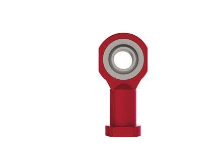
65 E-Series Accessories 3 End Fittings 65 Top Plate apacity (kn) ØA ØB D ØE x QTY 9 x 4 11 x x 4 18 x 4 x 4 6 x 4 33 x 4 33 x 4 51 x 4 51 x 6 5 x 8 ØF (PD) L M10 x 1.5 M1 x 1.75 M0 x.5 M4 x 3 M36 x 4 M48 x 5 M7 x 4 M100 x 4 M15 x 4 M145 x 6 M180 x 8 M #1 Inverted Upright levis Plate apacity (kn) ØA ØB D E J L M10 x 1.5 M1 x 1.75 M0 x.5 M4 x 3 M36 x 4 M48 x 5 M7 x 4 M100 x 4 M15 x 4 M145 x 6 M180 x 8 M #1 Inverted Upright Fork End apacity (kn) ØA B D E F G ØJ L M10 x 1.5 M1 x 1.75 M0 x.5 M4 x 3 M36 x 4 M48 x 5 M #1 Inverted Upright Available on Request Available on Request Available on Request Available on Request Available on Request Rod End apacity (kn) A ØB ØD F ØG H J K L M10 x 1.5 M1 x 1.75 M0 x 1.5 M4 x M36 x 3 M45 x 3 M #1 Upright Inverted Available on Request Available on Request Available on Request Available on Request Available on Request Note 1. M = For Machine Screw Jacks

66 3 66 E-Series Accessories Machine Screw Jack Bellows Boots Features Protects the screw from dust and dirt Guards against moisture and corrosive contaminants Helps maintain the proper lubrication Boots are made of P.V.. coated nylon with sewn construction. Other materials are available for applications involving high temperatures, highly corrosive atmospheres and other special conditions. Boot Dimensions Model A B D E EMT EMT EMT EMT EMT EMT EMT EMT EMT EMT EMT øa øb ø D F E F Model EMT0005 EMT0010 EMT005 EMT0050 EMT0100 EMT000 EMT0300 EMT0500 EMT1000 EMT1500 EMT F = Bellows boot minimum closed thickness, - = Not applicable losed Heights Threaded End Top Plate levis End Rod End Fork End G G G + H G + I G + J Notes for all metric machine screw jacks with bellows boots 1. Supplied complete with a set of corrosion-resistant jubilee clips () suitable for fitting over collar diameters.. ontrol tapes are fitted (approximately 0 mm increase to outer diameter). 3. For horizontal installation exceeding 450 mm of travel, internal boot guides are recommended. 4. ustomers with threaded end screw jacks must provide a fixing for the unattached collar ( ). 5. Bellows boots for Rotating Screw Jacks consult Power Jacks Ltd. 6. For other sizes, strokes and materials please consult Power Jacks Ltd. 7. All dimensions in millimetres unless otherwise stated. 8. Dimensions subject to change without notice. 9. Screw Jack mounting plate and bellows boot mounting plate are usually all part of the customers superstructure ( ). For other options consult Power Jacks.
67 E-Series Accessories 3 Machine Screw Jack Bellows Boots 67 losed Height for all Upright Machine Screw Jacks and Anti-Rotation (Keyed) Types G H I J Model EMT0005 EMT0010 EMT005 EMT0050 EMT0100 EMT000 EMT0300 EMT0500 EMT1000 EMT1500 EMT Extra losed Height for levis Extra losed Height for Fork Extra losed Height for Rod End Request Request Request Request Request Request Request Request Request Request losed Height for all Upright Machine Screw Jacks with Anti-Backlash G H I J Model EMT0005 EMT0010 EMT005 EMT0050 EMT0100 EMT000 EMT0300 EMT0500 EMT1000 EMT1500 EMT Request Request Request Request Request Request Request Request Extra losed Height for levis Request Request Extra losed Height for Fork Request Request Request Request Request Extra losed Height for Rod End Request Request Request Request Request losed Height for all Upright Machine Screw Jacks with Anti-Backlash & Anti-Rotation (Keyed) G H I J Model EMT0005 EMT0010 EMT005 EMT0050 EMT0100 EMT000 EMT0300 EMT0500 EMT1000 EMT1500 EMT Request Request Request Request Request Request Request Request Extra losed Height for levis Request Request Extra losed Height for Fork Request Request Request Request Request Extra losed Height for Rod End Request Request Request Request Request
68 3 68 E-Series Accessories Machine Screw Jack Bellows Boots losed Heights Threaded End Top Plate levis End Rod End Fork End K K K K+L K+P K+N Boot Mounting Plate, to suit collar size. Typically ØB x (E+5 mm fitting allowance) thick. Screw jack Mounting Plate, M thick. Alter thickness to suit application. losed Height for all Inverted Machine Screw Jacks Standard or Anti-Backlash or Anti-Rotation (Keyed) Model EMT0005 EMT0010 EMT005 EMT0050 EMT0100 EMT000 EMT0300 EMT0500 EMT1000 EMT1500 EMT000 M Mounting Plate K L Extra losed Height for levis N Extra losed Height for Fork Request Request Request Request Request P Extra losed Height for Rod End Request Request Request Request Request
69 E-Series Accessories 3 Machine Screw Jack Bellows Boots 69 losed Heights Threaded End Top Plate levis End Rod End Fork End K K K K+L K+P K+N Boot Mounting Plate, to suit collar size. Typically ØB x (E+5 mm fitting allowance) thick. Screw jack Mounting Plate, M thick. Alter thickness to suit application. losed Height for all Inverted Machine Screw Jacks with Anti-Backlash and Anti-Rotation (Keyed) Model EMT0005 EMT0010 EMT005 EMT0050 EMT0100 EMT000 EMT0300 EMT0500 EMT1000 EMT1500 EMT000 M Mounting Plate K L N P Request Request Request Request Request Request Request Request Extra losed Height for levis Request Request Extra losed Height for Fork Request Request Request Request Request Extra losed Height for Rod End Request Request Request Request Request

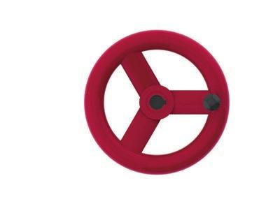
70 3 70 E-Series Accessories Stop Nuts & Hand Wheels Stop Nut Machine Screw Jack r a ( m m ) d e l U p r i g I n ve r t e d Ext Mo ht EMT EMT EMT EMT EMT EMT EMT EMT EMT EMT EMT Note These are full power stop nuts. They should only be used as an emergency stop safety feature. Hand Wheels d e l A B D H B o r e H W H W H W H W H W H W H W H W Mo E Ø Ø Ø Ø Ø Ø Ø Ø 40 Notes: 1. Material: Polished aluminium casting and rotating handle. Bored and keyed to BS435 Part 1 3. All dimensions in millimetres unless otherwise stated 4. Other types of hand wheels are available on request. onsult Power Jacks.


 E O apacity A B B1 D ØE F G H I I1 J K O P Q ØR (h6) S T U 5kN 70 4 1 35 11 1 65 0 0 10 159")
71 A B D J U P I H I G F E-Series Accessories 3 Trunnion Mounts 71 Base mounted trunnions are an ideal bolt-on accessory for a screw jack to add a pivot point to the gearbox of the screw jack. These base mounted trunnions can be used for both translating and rotating screw jacks with any lifting screw type. Available in both male or female designs with the option to add standard trunnion feet. Most designs offer trunnions in mounting positions. If you need trunnions fitted at another position on a screw jack then please contact us as we can provide customised trunnion mounts to suit your exact applications needs 5kN and 10kN Trunnion Mounts I 1 R S T K I 1 B 1 ( x) E O apacity A B B1 D ØE F G H I I1 J K O P Q ØR (h6) S T U 5kN kN

72 W V U X U Z W V X Z I I I I 3 7 E-Series Accessories Trunnion Mounts 5kN to 500kN Trunnion Mounts I 1 S R f 7 T T S R f 7 I 1 T I 1 Y I 1 Y


73 L A B D B A J D P H H I I G G F F E-Series Accessories Trunnion Mounts kN to 500kN Trunnion Mounts K I 1 B 1 ( x) E O I 1 ( N ) M B 1 ( x) E O apacity A B B1 D ØE F G H I I1 J K L 5kN kN kN kN kN kN apacity M N O P Q ØR (f7) S T U V W X Y Z 5kN kN kN kN kN kN

 S T U ØV W X")
74 A B D J U X Z V W H I I I F 3 74 E-Series Accessories Trunnion Mounts 1000kN to 000kN Trunnion Mounts I 1 R S T I 1 Y K I 1 ( 4x) E B 1 D 1 O G Note: Trunnion feet for 300kN and 500kN models are available on request apacity A B B1 D ØE F G H I I1 J K L 1000kN kN kN apacity M N O P Q ØR (f7) S T U ØV W X Y Z 1000kN N/A N/A kN N/A N/A kN N/A N/A

75 E-Series Accessories Motor Adapter 3 75 Standard adapters for 5 kn - 00 kn metric machine screw and ball screw jacks Designed for standard IE frame sizes Allows direct motor coupling on either side of the screw jack input shaft omplete with drive coupling and mounting hardware Note When direct coupling a motor to a screw jack, it is necessary to match motor power to screw jack load so the motor does not exceed the maximum power for the screw jack gear set. D B A Motor Adapters Frame Size Motor Mounting apacity (kn) A B Ø ØD A B Ø ØD A B Ø ØD A B Ø ØD 71 B B B B B B Notes: 1. Motor Adapters for IE Frames with B5 Flange mounts available on request.. Motor Adapters for screw jacks of capacities 300kN and above are available on request. 3. Adapters for geared motors are available on request for all types of geared motor or gear head. 4. Motor Adapters for Servo Motors available on request. 5. Motor Adapters for NEMA Frame motors are available on request. 6. All dimensions in millimetres unless otherwise stated. 7. Dimensions subject to change without notice.
 or Normally Open (NO) switching. Sensor has rugged one-piece metal housing.")
. Full 360 visibility for switching with 4 yellow LED s at 90 offset.")
 Switch Dia (mm) A1 (mm) Upright & Inverted Machine Screw Jacks A (mm) B (mm) (mm) D (Ømm) F (mm)")
76 3 76 E-Series Accessories Limit Switches on over Pipe End of Travel Proximity Sensors Sensor Kit ØD Inductive Proximity Sensors as standard, others available on request. No contact so no wearing parts. wire sensor for either Normally losed (N) or Normally Open (NO) switching. Sensor has rugged one-piece metal housing. Optical setting aid with LED colour settings:- Red LED indicates just in sensing range. Yellow LED only indicates within 80% safe sensing range. M1 plug in connection for fast change-ability. M1 sockets available straight or angled with 5-m cable (other cable lengths available on request). Full 360 visibility for switching with 4 yellow LED s at 90 offset. Sensor kit includes - sensor, mounting ring, target ring and modification to screw jacks cover pipe. over Pipe ØD Switch Switch F MOUNTING PLATE A1 B over Pipe Switch Switch B A apacity Rating (kn) Switch Dia (mm) A1 (mm) Upright & Inverted Machine Screw Jacks A (mm) B (mm) (mm) D (Ømm) F (mm) Switch Adjustment (mm) ± ± ± ± ± ± ± ± ± On Request 000 On Request Note 1. All dimensions in mm unless otherwise stated. End of Travel Electro-Mechanical Switches The screw jacks can be fitted with electro-mechanical limit switches in a similar design. For dimensions please consult Power Jacks Ltd.

77 E-Series Accessories Rotary Limit Switch - RLS 3 77 Rotary limit switches can be used as end of travel limit switches, with the option of intermediate switches as well. These units are mounted onto a screw jacks free worm shaft and offer an alternative where bottom pipe mounted limit switches are not possible e.g. rotating screw jacks. Up to 8 limit switches can be accommodated in one enclosure (IP66). Operating temperature -40 to +80. More RLS-51 rotary limit switch details in System omponents section of design guide Screw Jack apacity (kn) 5 50 Adapter Std. Std. A B Mounting Part ø Part A B ø B5 O O B14 P P Screw Jack apacity (kn) Adapter Std. Std. A B Mounting Part ø Part A B ø B5 P P B14 O O The mounting kit includes the flexible coupling and drive adapter. Gear Size Usable revs. selected Usable revs. theoretical with 15 cam discs Gear Ratio 1 rev. of the drive shaft - corresp. to an ang. motion of cam disc = hange - over contact reset rev. at driving shaft Max drive speed (RPM) Min drive shaft speed (only for change - over contact) * * * L1 (mm) Limit Switches Note 1. More than 8 contacts on request.. Dimensions with more than 8 contacts and with special executions, eg. potentiometer, on request. 3. RLS-51 B5 Flange thickness = 4mm. 4. Options available include Anti-condensation heaters, potentiometer, pulse transmitter, encoder, aluminium housing and VBG-70 STAGE technology. 5. Mounting kits available for all screw jacks. For those not listed, consult Power Jacks.
78 E-Series 4 ENGINEERING GUIDE USEFUL PERFORMANE & OPERATIONAL DETAIL FOR SREW JAKS
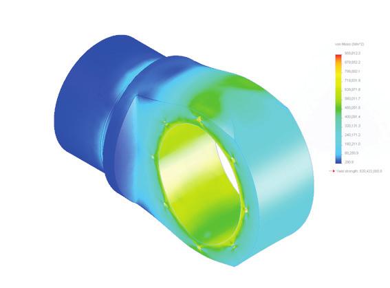
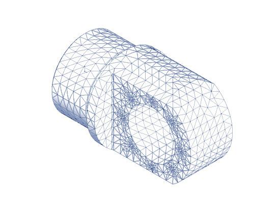
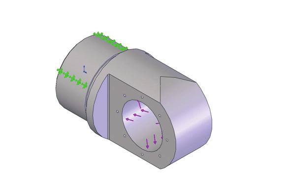

79 Engineering Guide Screw Jack Performance 4 79
E - S E R I E S S C R E W J A C K S
 E-SERIES SREW JAKS 1 2 Screw Jack Design Guide ompany Overview Best engineered solution for precision linear actuation, power transmission & jacking systems. apability OUR EXPERTISE HAS BEEN BUIT ON A
E-Series Screw Jacks. Metric Machine Screw Jack. Stainless Steel Machine Screw Jack. Metric Ball Screw Jack
 E-Series Screw Jacks Metric Machine Screw Jack Stainless Steel Machine Screw Jack Metric Ball Screw Jack E-Series 1 BEST ENGINEERED SOLUTION FOR PRECISION LINEAR ACTUATION, POWER TRANSMISSION & MECHANICAL
C - S E R I E S S C R E W J A C K S
 -SERIES SREW JAKS 1 2 Screw Jack Design Guide ompany Overview Best engineered solution for precision linear actuation, power transmission & jacking systems. & E-Series Screw Jacks ompany Overview apability
C-SERIES S-SERIES. Metric Machine Screw Jacks
 -SERIES S-SERIES Metric Machine Screw Jacks Power Jacks are a manufacturer focused on providing customers with the best engineered solution for precision linear actuation, power transmission and mechanical
DESIGN WITH POWER PRECISION SCREW JACKS. ELECTRIC LINEAR ACTUATORS. PLANETARY ROLLER SCREWS. SPIRAL BEVEL GEARBOXES.
 PREISION SREW JAKS. EETRI INEAR ATUATORS. PANETARY ROER SREWS. SPIRA BEVE GEARBOXES. DESIGN WITH POWER POWER JAKS td South Harbour Road raserburgh Aberdeenshire AB43 9BZ Scotland (UK) Tel: +44 (0)1346
C-SERIES S-SERIES. Metric Machine Screw Jacks
 -SRIS S-SRIS Metric Machine Screw Jacks 02 www.powerjacks.com Power Jacks More than just a screw jack Power Jacks are a manufacturer focused on providing customers with the best engineered solution for
C-SERIES S-SERIES EMA LINEAR ACTUATORS. Metric Machine Screw Jacks.
 C-SERIES S-SERIES Metric Machine Screw Jacks EMA LINEAR ACTUATORS 0i 02 Power Jacks has a proud engineering heritage dating from the earliest years of the 20th Century. A heritage that is about excellence:
Power Jacks have taken time, engineering excellence and the best people to produce the ultra compact Neeter Drive gearbox.
 202 www.powerjacks.com Power Jacks have taken time, engineering excellence and the best people to produce the ultra compact Neeter Drive gearbox. Our expertise has been built on a history of engineering
S-SERIES Translating Screw Jack 50kN
 Translating Screw Jack 50kN Performance ST050 Screw Jack Model 4 S-050 apacity kn 50 ead Screw 1 iameter (mm) 40 ead (mm) 9 18 Option 1 6:1 ear Ratios Option 2 24:1 Option 3 8:1 (OR) 4 x Turns of worm
C-SERIES S-SERIES. Metric Machine Screw Jacks EMA LINEAR ACTUATORS
 C-SERIES S-SERIES Metric Machine Screw Jacks EMA LINEAR ACTUATORS Power Jacks has a proud engineering heritage dating from the earliest years of the 20th Century. A heritage that is about excellence: about
Lifting & Positioning Solutions for the Nuclear Industry. Research Power Plants Waste Treatment Decommissioning
 Lifting & Positioning Solutions for the Nuclear Industry Research Power Plants Waste Treatment Decommissioning 02 Company Capability OUR EXPERTISE HAS BEEN BUILT ON A HISTORY OF MORE THAN 100 YEARS OF
SYSTEM COMPONENTS COUPLINGS & DRIVE SHAFTS
 SYSTEM COMPONENTS COUPINS & DRIVE SHAFTS 2 Couplings & Drive Shafts FU RANE OF COUPIN AND DRIVE SHAFTS SO YOU CAN BUID COMPETE JACKIN SYSTEMS. C & E-Series Screw Jacks Company Overview Capability 1 3 OUR
C-SERIES Rotating Screw Jack 100kN
 -SRIS Rotating Screw Jack 100kN MR100 olumn Strength ree Pinned uided ixed Pinned ixed PRMISSI OMPRSSIV O (K) 1.2.10 4 1.1.10 4 1.10 4 9000 8000 7000 6000 5000 4000 3000 2000 1000 OUMN NTH (mm) 0 IX/UI
SPIRACON. ROLLER SCREWS SPIRACON PRODUCT CATALOGUE
 SPIRACON ROLLER SCREWS PRODUCT CATALOGUE SPIRACON www.powerjacks.com TOTAL CAPABILITY IN ACTUATION Power Jacks is a world leader and pace-setter in the field of mechanical linear actuation and power transmission,
Gears And Gear Drives (India) Pvt Ltd
 Pvt Ltd") Gears And Gear Drives (India) Pvt Ltd Design and manufacturers of Lifting Systems An ISO 9001-2015 Certified Company. Seshagiri Managing Director Gears and Gear Drives (India) Pvt Ltd Motion Technology,
Gears And Gear Drives (India) Pvt Ltd Design and manufacturers of Lifting Systems An ISO 9001-2015 Certified Company. Seshagiri Managing Director Gears and Gear Drives (India) Pvt Ltd Motion Technology,
 www.motiontech.com.au Copyright SERVOMECH This catalogue contents are under publisher copyright and may not be reproduced unless permission is agreed. Every care has been taken to ensure the accuracy of
Benzlers Screw Jacks. Benzlers Screw Jacks CBD-2.00GB0613
 enzlers Screw Jacks enzlers Screw Jacks D-2.00G0613 ATEX ompliance Assured Total compliance with the ATEX Directive safeguarding the use of industrial equipment in potentially explosive atmospheres is
The gear boxes can be run at the same speeds as the actuator models. Do not exceed torque ratings.
 1. What is the lifting torque required? The lifting torque for a single actuator depends on the load, the worm gear ratio, type of screw (machine cut or ball screw) and the pitch of the lifting screw.
SYSTEM COMPONENTS ELECTRIC MOTORS
 SYSTM COMPONNTS LCTRIC MOTORS 2 lectric Motors POWR JACKS CAN SUPPLY LCTRIC MOTORS OR ALL APPLICATIONS WHTHR AC OR C MOTORS AR RQUIR. C & -Series Screw Jacks Company Overview Capability 1 3 OUR XPRTIS
Linear actuators ILA Series
 Linear Actuator ILA Series without input drive, with flange and input shaft Linear Actuator ILA Series with input drive - with 2 bevel gearmotors - with single bevel gearmotor - with helical coaxial or
SGT screw jack. Product description. SGT 5 to SGT 1000 screw jack Both trapezoidal and ball screw versions.
 Product description SGT to SGT screw jack Both trapezoidal and ball screw versions ALBERT-SGT-screw jacks are electromechanical transmission components suitable for a wide spectrum of industrial machinery.
using Class 2-C (Centralizing) tolerances. Jack lift shaft lead tolerance is approximately 0.004" per foot.
 tolerances. Jack lift shaft lead tolerance is approximately 0.004 per foot.") WORM GEAR JACK MODELS WORM GEAR ACTIONJAC JACKS Jack systems are ruggedly designed and produced in standard models with load handling capacities from 1/4 ton to 100 tons. They may be used individually
WORM GEAR JACK MODELS WORM GEAR ACTIONJAC JACKS Jack systems are ruggedly designed and produced in standard models with load handling capacities from 1/4 ton to 100 tons. They may be used individually
JTW-SERIES MACHINE SCREW JACK
 J A C TO N I N D U S T RY C O., LT D L I F T I N G S Y S T E M S S O L U T I O N S TEL: 86-769-81585810, 81585852 SKYPE: jactonjack EMAIL: sales@screwactuator.com WEB: www.screwactuator.com SERIES MACHINE
JT-SERIES TRAPEZOIDAL SCREW JACKS
 J A C TO N I N D U S T RY C O., LT D L I F T I N G S Y S T E M S S O L U T I O N S TEL: 86-769-81585810, 81585852 SKYPE: jacjack EMAIL: sales@screwactuator.com WEB: www.screwactuator.com JT-SERIES TRAPEZOIDAL
Features. Machine Screw Actuators
 Features Positive, mechanical positioning Uniform lifting speed Multiple arrangements Anti-backlash (optional) Machine Screw Top Plate - Must be bolted to lifting member to prevent rotation except when
Screw jacks MA Series
 Screw jacks MA Series Screw jacks MA Series with travelling screw (Mod.A) STRUCTURAL ELEMENTS 1 10 11 8 7 6 1 3 13 4 9 14 8 11 10 5 6 7 1 - acme screw in steel C 43 (UNI 7847), whirled thread - worm shaft
CUBIC SCREW JACKS. Features & Benefits. Specifications
 CUBIC SCREW JACKS Features & Benefits Versatile Mounting - Unit can me mounted upright or inverted Clean surface - Easy to maintain in dirty environments Contemporary design for improved aesthetics Fast
Screw Jacks. Screw Jacks CBD-2.00GB0613
 VARIMAX AG, Antriebstechnik, Normannenstrasse 14, Postfach 762, -3018 ern Tel. +41 (0)31 990 00 70 e-mail info@varimax.ch Fax +41 (0)31 990 00 71 web www.varimax.ch Screw Jacks Screw Jacks D-2.00G0613
FPO See DN-SCCAT_COVER-SPINE.indd
 FPO See DN-SCCAT_COVER-SPINE.indd SUPERCYLINDER TABLE OF CONTENTS INTRODUCTION Duff-Norton manufactures the industry s broadest range of high capacity electric cylinders. From 2 to 25 tons (17 to 186 kn),
Acme Screw Jacks. Catalogue
 Acme Screw Jacks Catalogue SERVOMECH Screw Jacks MA Series Screw Jacks - high efficiency Max. duty cycle: travelling screw: 40 % over 10 min (30 % over 1 hour) travelling nut: 30 % over 10 min (20 % over
Some customers opt to manually power their actuators. In those cases hand wheels are usually the preferred drive component.
 EXTERNAL POWER SOURCE AND GEAR REDUCER All actuators require an external power source. Whether this power source be an electric motor or hand wheel Duff-Norton has the required component. Customers who
Servomechkaramoottorit
 Solutions for power transmission Servomechkaramoottorit www.konaflex.fi INDEX 1 Servomech 1. THE PRODUCT 1.1 SERVOMECH Linear Actuators......................... Page 2 1.2 SERVOMECH Linear Actuators range............................
SCREW JACK POWER TRANSMISSION COMPONENTS TYPICAL SYSTEM ARRANGEMENTS
 TYPICAL SYSTEM ARRANGEMENTS Duff-Norton offers all of the components necessary to complete your power transmission system, whether it consists of a single actuator or a multiple actuator arrangement. We
NEW. Linear Ball Bushing Bearings and 60 Case Shafting. Profile Rail Linear Guides
 Linear Ball Bushing Bearings and 60 Case Shafting Thomson invented the ball bushing bearing over 60 years ago and has since been the recognized leader in this field. Our linear products provide low friction,
Electric cylinders CASM
 Electric cylinders CASM 32-4-63 Contents Product description 4 Motors and gearboxes 6 Manuals 1 3D models 1 Linear unit 3 12 Linear unit 4 14 Linear unit 63 16 linear unit 18 Actuator 32 2 Actuator 4 32
SERVOMECH linear actuators are electromechanical cylinders able to transform a rotary movement into a linear motion.
 1.1 SERVOMECH LINEAR ACTUATORS SERVOMECH linear actuators are electromechanical cylinders able to transform a rotary movement into a linear motion. Developed and manufactured for industrial applications,
Series BD Screw Jacks
 www.radicon.com Series BD Screw Jacks Technical Up to - 100Te / 5m/min Screw Jacks CBD-1.00GBD0111 SERIES BD PRODUCTS IN THE RANGE Serving an entire spectrum of mechanical drive applications from food,
ANTI-BACKLASH. ACTUATORS ¼ to 250 TONS. Why Anti-Backlash Control is Important
 ¼ to 250 TONS Why Anti-Backlash Control is Important Even the best manufacturing processes produce clearances between a screw and a mating nut. In applications where loads may be in either direction, backlash
Accessories for screw jacks type SGT
 Product description Accessories for Albert SGT screw jacks Both trapezoidal and ball screw version The comprehensive range of Albert accessories for screw jacks provides the designer with the means to
Sizes 50, 65, 80. Presence of internal channels for re-lubrication Large range of axis mounting accessories
 > Series 5E electromechanical axis C_Electrics > 207 Series 5E electromechanical axis New models Sizes 50, 65, 80 Multiposition system with transmission of the movement with toothed belt Suitable for high
Linear Drive with Ball Screw Drive Series OSP-E..SB
 Linear Drive with Ball Screw Drive Series OSP-E..SB Contents Description Data Sheet No. Page Overview 1.30.001E 47-50 Technical Data 1.30.002E-1 to 5 51-55 Dimensions 1.30.002E-6, -7 56-57 Order instructions
METRIC BALL SCREW JACKS
 METRIC BA METRIC BA With over twenty-five years of experience manufacturing precision worm gear screw jacks, Nook Industries has expanded the ActionJac offering to include metric models providing design
BEARINGS The lower bearing assemble is constructed to allow continuous operation when fully submerged in wastewater.
 GENERAL SPECIFICATION INTENT The equipment to be supplied by manufacturer includes the screw pumps, support for the drive unit, profile plates, motors, gearboxes, couplings, guards, upper and lower bearing
Candy Coup-Link OVER YEARS OF INNOVATION
 Candy Coup-Link Zero-backlash, flexible-shaft couplings High torque, excellent response Accommodates misalignment and shaft endplay Aluminum and stainless steel options Inch and metric bores available
ACME SCREW LINEAR ACTUATOR. Current [A] PERFORMANCES with AC 3-phase 50 Hz 230/400 V or 1-phase 50 Hz 230 V motor
![ACME SCREW LINEAR ACTUATOR. Current [A] PERFORMANCES with AC 3-phase 50 Hz 230/400 V or 1-phase 50 Hz 230 V motor](/thumbs/89/99042793.jpg "ACME SCREW LINEAR ACTUATOR. Current [A] PERFORMANCES with AC 3-phase 50 Hz 230/400 V or 1-phase 50 Hz 230 V motor") ACME SCREW LINEAR ACTUATOR CLA 28 OVERALL DIMENSIONS La = Lc + Stroke Stroke Lc T Standard head with threaded hollow bore BA Motor cable length 0.3 m Bronze bushes depth 17 Lc [mm] T [mm] Length [mm] +
ACME SCREW LINEAR ACTUATOR CLA 28 OVERALL DIMENSIONS La = Lc + Stroke Stroke Lc T Standard head with threaded hollow bore BA Motor cable length 0.3 m Bronze bushes depth 17 Lc [mm] T [mm] Length [mm] +
Contents. Page. 1. Product description. 2. The AXC line of linear axes. 3. AXLT line of linear tables. AXC and AXS product overview...
 SNR Industry Contents Page 3 1. Product description AXC and AXS product overview... 6-8 Dynamic load ratings of the linear motion systems... 9 Compact modules... 10-11 Linear tables... 12 Telescopic axes...
Shrink Discs, Smart-Lock & Shaft Couplings
 RINGFEDER Products are available from MARYLAND METRICS Shrink Discs, Smart-Lock & Shaft Couplings US 08 2009 Partner for performance RINGFEDER Products are available from MARYLAND METRICS P.O. Box 261
Linear actuators ATL Series
 . TECHNICAL DATA - acme screw linear actuators ATL Series ATL 63 ATL 80 ATL 100 ATL 15 SIZE 50 60 90 100 150 Push rod diameter [mm] 70 90 115 150 00 Outer tube diameter [mm] 30 35 40 60 80 Front attachment
Victory A-Series Actuators PRODUCT CATALOG V55A V43A FG1 V32A FG2 V26A
 Victory -Series ctuators PROUT TLOG V55 with parallel motor mounting V4 G1 with parallel motor mounting V2 G2 with inline motor mounting V26 with inline motor mounting Longer, aster, and More Reliable
PRODUCT PROGRAMME. Gear drive solutions
 PRODUCT PROGRAMME Gear drive solutions Dedicated gear drive BJ-Gear A/S is one of the leading companies within developing, manufacturing and assembling gearboxes, geared motors, linear products, special
Linear Actuator with Ball Screw Series OSP-E..S. Contents Description Overview Technical Data Dimensions 79
 Linear Actuator with Ball Screw Series OSP-E..S Contents Description Page Overview 71-74 Technical Data 75-78 Dimensions 79 71 The System Concept ELECTRIC LINEAR ACTUATOR FOR HIGH ACCURACY APPLICATIONS
CATALOGUE MEDIUM TO HEAVY DUTY IDLER
 CATALOGUE MEDIUM TO HEAVY DUTY IDLER Sandvik Materials Handling PULLEYS, IDLERS AND MATERIALS HANDLING SYSTEMS INDEX 3 ROLL INLINE CARRY & IMPACT PAGE 3 3 ROLL INLINE PLAIN P/A TRAINER PAGE 5 SINGLE ROLL
Linear Actuator with Toothed Belt Series OSP-E..B
 Linear Actuator with Toothed Belt Series OSP-E..B Contents Description Data Sheet No. Page Overview 1.20.001E 21-24 Technical Data 1.20.002E-1 to 5 25-29 Dimensions 1.20.002E-6 30 Order Instructions 1.20.002E-7
Electric Actuators Available Exclusively Through
 Electric Actuators Available Exclusively Through Custom Application Solutions are Our Specialty Compact Automation offers durable, reliable and innovative industrial solutions with high value and low life-cycle
Electric cylinders CASM-100
 Electric cylinders CASM-100 Contents Electric cylinder CASM-100.............................4 Product description.................................5 System overview...................................6
L1 (Standard Motor Length) L2 (Brake Motor Length)
 L2 (Brake Motor Length)") HepcoMotion Geared Motor Option The optional geared motor will be the preferred choice for many applications as it provides an excellent combination of power, accuracy, flexibility and value. HepcoMotion
HepcoMotion Geared Motor Option The optional geared motor will be the preferred choice for many applications as it provides an excellent combination of power, accuracy, flexibility and value. HepcoMotion
acme & ball screws actuators linear motion drive components engineering ingenuity
 P R O D U C T O V E R V I E W acme & ball screws actuators linear motion drive components engineering ingenuity w w w. n o o k i n d u s t r i e s. c o m CC linear actuators CC Linear Actuators are ball
self locking jack screw driven scissor mechanism
 self locking jack screw, worm gear screw jack style scissor lift system, acme screw jack lifting system for scissor lift table in singapore Custom material handling and lifting solutions with hydraulically,
BALL SCREW LINEAR ACTUATOR OVERALL DIMENSIONS LENGTH
 BALL SCREW LINEAR ACTUATOR BSA 2 OVERALL DIMENSIONS Stroke La =Lc + Stroke Lc T Capacitor Rear bracket Pin SP Standard head with threaded hollow bore BA depth 7 Stroke end reed switches FCM (brake motor)
INTELLIGENT DRIVE SYSTEMS, WORLDWIDE SERVICES INTELLIGENT DRIVESYSTEMS, WORLDWIDE SERVICES
 INTELLIGENT DRIVE SYSTEMS, WORLDWIDE SERVICES INTELLIGENT DRIVESYSTEMS, WORLDWIDE SERVICES EN DRIVE SOLUTIONS FOR SEWAGE PLANTS NORD DRIVESYSTEMS Intelligent Drivesystems, Worldwide Services NORD DRIVE
Planetary. Roller Screw. We invite you to explore and challenges for the future of Kim
 Planetary Roller Screw We invite you to explore and challenges for the future of Kim ontents 05 08 18 24 25 Kim o., td. Design Guidelines Product Information Service Range Application onfiguartion Worksheet
Drives for food & beverage machinery. Low and high aseptic. Lenze. ideas in motion
 Drives for food & beverage machinery Low and high aseptic Lenze ideas in motion A wide range of Lenze drive products are suitable for use in food & beverage machinery, also other equipment in arduous environments.
UNI-LIFT System Design
 UNI-LIFT System Design Key Points to Consider When Properly Sizing an Actuator Total system load Application loading conditions Operating intervals of the actuator Linear velocity requirements Ambient
LINEAR ACTUATORS. hepcomotion.com
 LINEAR ACTUATORS hepcomotion.com PDU2 Belt Driven DLS Belt Driven 3 4 SBD Belt Driven A SDM Ball Screw HDCS Heavy Duty Ball Screw 8 9 LINEAR ACTUATORS ctuator HDLS Heavy Duty Belt Driven PSD Ball Screw
Linear Actuator with Ball Screw Series OSP-E..S. Contents Description Overview Technical Data Dimensions 89
 Linear Actuator with Ball Screw Series OSP-E..S Contents Description Page Overview 79-82 Technical Data 83-88 Dimensions 89 79 The System Concept ELECTRIC LINEAR ACTUATOR FOR HIGH ACCURACY APPLICATIONS
* Contents. Company Profiles...2. Introduction...3. Technical Datasheet...4. Selection Guide... 5~9. Screw Jack Lift Systems...
 0 * Contents Company Profiles...2 Introduction....3 Technical Datasheet.......4 Selection Guide..... 5~9 Screw Jack Lift Systems.... 10~11 Screw Top End Types Dimensions. 12 RN-0.5T~RN-100T Dimensions......13~24
ACME AND BALL SCREWS & NUTS DESIGN GUIDE
 ACME AND BALL SCREWS & NUTS DESIGN GUIDE SCREWS & NUTS TABLE OF CONTENTS Since 1883, Duff-Norton has been at the forefront of precision motion technology, providing a continued commitment to leading edge
Heavy-Duty Rod Ends - Male with integral spherical plain bearing
 Heavy-Duty Rod Ends - Male with integral spherical plain bearing 65700 Order No. Thread (hand) d 1 l 1 d 2 d 3 d 4 l 2 l 3 X g H7 65700.W0005 Right 5 33 M 5 11,11 18 20 9 14 65700.W0006 Right 6 36 M 6
Screw Jacks. Lifting >> Tilting >> Lowering >> Feeding sm. MARYLANDMETRICS phones: (800) (410) faxes: (800) (410)
 (410) faxes: (800) (410)") Cubic Screw Jack Family MULI, JUMBO MULI, JUMBO Lifting >> Tilting >> Lowering >> Feeding sm Cubic Screw Jacks RHINO MARYLAND METRICS offers: Screw Jacks Superior performance. Superior design. MARYLANDMETRICS
Cubic Screw Jack Family MULI, JUMBO MULI, JUMBO Lifting >> Tilting >> Lowering >> Feeding sm Cubic Screw Jacks RHINO MARYLAND METRICS offers: Screw Jacks Superior performance. Superior design. MARYLANDMETRICS
The new performance class...
 The new performance class... 10/2017 EP(X)-II 30/40 EP(X)-II 30/40 twin tube actuator The latest generation of twin tube units Move-Tec EP(X)-II 30/40 Your application takes centre stage slow langsam A
POSITION TRANSMITTERS
 POSITION TRANSMITTERS GENERAL DESCRIPTION Jordan Control s Series of position transmitters are rugged, compact industrial components that couple a precision feedback component and/or limit switches to
LINEAR MOTION AND ALIGNMENT
 LINAR MOTION AN ALIGNMNT Section Introduction to Linear Shift Mechanisms 094 Linear Shift Mechanism Actuation Options 096 Standard Linear Shift Mechanism (LSM ) 098 Long Travel Linear Shift Mechanism (LSML
HEAVY DUTY WORM GEARBOX MODEL SBWG
 FEATURES AND BENEFITS The SBWG model is suitable for use with Butterfly, Plug and any other type requiring quarter turn motion for thrust and torque applications High Tensile Aluminium bronze material
Position Transmitters. Instruction Manual. Established Leaders in Valve Actuation. Electric Actuators and Control Systems
 Electric Actuators and Control Systems Established Leaders in Valve Actuation Position Transmitters Instruction Manual Publication P973E Issue 08/09 Instruction Manual IM-0665 Position Transmitters Where
System Overview - Screw Jacks S
 3. System Overview Screw Jacks S 3.3, Standing Spindle S Fixing flange BF Pivot bearing head SLK Motor Rod end KGK Bellow FB Spiral spring SF Rotary pulse encoder DIG Coupling KUZ Motor flange MF Lubrication
IW Quarter-turn. Keeping the World Flowing. IW Quarter-turn Gear Series. Gearboxes
 IW Quarter-turn Gear Series The IW series of quadrant worm operators has been designed with customer stocking in mind, and features a removable steel output sleeve to facilitate bore and keyway machining.
Why Anti-Backlash Control is Important. Features. Anti-Backlash Actuators
 Why Anti-Backlash Control is Important Even the best manufacturing processes produce clearances between a screw and a mating nut. In applications where loads may be in either direction, backlash can result
DRIVE-TECHNOLOGY INKOMA - GROUP. Accessories for screw jacks type SGT. Maschinenfabrik ALBERT GmbH Technologiepark 2 A Gampern - Austria
 DRIVETECHNOLOGY ALBERTINKOMA GROUP Accessories for screw jacks type SGT Maschinenfabrik ALBERT GmbH Technologiepark 2 A 81 Gampern Austria phone: +3/(0)76823 fax: +3/(0)7682399 email: office@albert.at
Profile rail guides LLT
 Profile rail guides LLT Contents The SKF brand now stands for more than ever before, and means more to you as a valued customer. While SKF maintains its leadership as the hallmark of quality bearings throughout
SCHMIDT-KUPPLUNG GmbH
 Loewe GK About us Many years of experience For 50 years, we have been advising machine manufacturers as partners for compact coupling systems. Our experience in power transmission has given us extensive
Better. Faster. Smarter.
 Better. Faster. Smarter. Thomson has the products and know-how to help you design equipment that is better, faster, smarter. In a modern production environment, moving material quickly, accurately and
BALL SCREW LINEAR ACTUATOR OVERALL DIMENSIONS. MASS [Kg] STROKE T STROKE LENGTH STROKE LENGTH. standard brake CODE
![BALL SCREW LINEAR ACTUATOR OVERALL DIMENSIONS. MASS [Kg] STROKE T STROKE LENGTH STROKE LENGTH. standard brake CODE](/thumbs/76/73943073.jpg "BALL SCREW LINEAR ACTUATOR OVERALL DIMENSIONS. MASS [Kg] STROKE T STROKE LENGTH STROKE LENGTH. standard brake CODE") BALL SCREW LINEAR ACTUATOR OVERALL DIMENSIONS BSA 10 AC motor Stroke La =Lc + Stroke Lc Capacitor T Rear bracket SP Pin Standard head with threaded hollow bore BA 80 depth 17 Stroke end reed switches FCM
BALL SCREW LINEAR ACTUATOR OVERALL DIMENSIONS BSA 10 AC motor Stroke La =Lc + Stroke Lc Capacitor T Rear bracket SP Pin Standard head with threaded hollow bore BA 80 depth 17 Stroke end reed switches FCM
HepcoMotion PSD80. screw driven linear actuator
 HepcoMotion PSD80 screw driven linear actuator Introduction The HepcoMotion PSD80 is a new screw driven linear unit, which is a companion to the popular and cost-effective PDU2 range of belt driven units,
FUNCTION OF A BEARING
 Bearing FUNCTION OF A BEARING The main function of a rotating shaft is to transmit power from one end of the line to the other. It needs a good support to ensure stability and frictionless rotation. The
Steering Test Rigs. The World of Steering Test Machines. A world of experience TEST AND MOTION SIMULATION 2
 Steering Test Rigs The World of Steering Test Machines Steering column assemblies, are by their nature extremely safety critical, thus the ability to test them accurately and repeatedly is extremely important.
1. Product overview Basic-Line-Module AXN Product description Basic-Line-Module AXN 4-5. Guide system Roller guide 6 Drive system Gear belt 7
 Directory Page 1. Product overview Basic-Line-Module AXN 3 2. Product description Basic-Line-Module AXN 4-5 Guide system Roller guide 6 Drive system Gear belt 7 3. Basic-Line-Modul AXN 45-Z 8-9 AXN 65-Z
HepcoMotion MHD Heavy Duty Track Roller Guidance System
 Motion Without Limits HepcoMotion MHD Heavy Duty Track Roller Guidance System product overview The HepcoMotion MHD system provides an accurate, durable and low friction linear guide which is particularly
POWERGEAR. Miniature NEW. Actual Size. Impressively small and incredibly powerful.
 MS-Graessner GmbH & Co. KG THE GEAR COMPANY POWERGEAR Miniature NEW Impressively small and incredibly powerful. Actual Size The bevel gearbox with minimum size at maximum performance and precision The
Screw Jack Systems MSZ Alu series
 Screw Jack Systems MSZ Alu series EN www.zimm.eu Z series and GSZ series screw jacks The preferred range with full range Z series Z series screw jacks are the preferred range with the largest number of
GEARBOXES for operation of industrial valves
 GEARBOXES for operation of industrial valves TECHNICAL DOCUMENTATION 2018 Part-turn gearboxes GS 50.3 GS 250.3 GS 50.3 GS 250.3 with base and lever GS 315 GS 500 GS 630.3 GHE 05.1 GHE 12.1 Multi-turn gearboxes
A superior alternative to hydraulic or pneumatic motion providing 15 times the life of a ball screw. Planetary Roller Screws
 A superior alternative to hydraulic or pneumatic motion providing 15 times the life of a ball screw Planetary Roller Screws Exlar Your Linear Motion Experts Exlar Corporation is committed to providing
Friction Management Solutions for Industrial Gear Drives
 Friction Management Solutions for Industrial Gear Drives A complete range of bearings and complementary services help the gear drive industry to meet ever-increasing requirements in product reliability
KTR Torque Limiters Overload Protection Systems
 KT Torque Limiters Overload Protection Systems UFLEX - Friction Disk - Zero Backlash Ball Detent KT SI - Ball/oller Bearing Style KT SI Compact - Zero Backlash Ball Detent Catalog Contents (Metric) Page
FLOOR TYPE HORIZONTAL MILLING MACHINES
 FLOOR TYPE HORIZONTAL MILLING MACHINES TARGET AND APPLICATION 2 AEROSPACE DIE & MOLD EARTH MOVING ENERGY OIL & GAS GENERAL MACHINING PAMA Speedmill is the ideal solution for all application requiring high
BEVEL GEAR UNITS ZZ-SERVOLINE
 BEVEL GEAR UNITS ZZ-SERVOLINE ZZ-SERVOLINE GEARBOX DESIGN AND FUNCTIONAL FEATURES Gear Ratios i= 3:1 i= 4:1 i= 5:1 i= 6:1 i= 8:1 i= 10:1 i= 12:1 i= 15:1 Spiral Bevel Gear KLINGELNBERG tooth system Hypoid
Compact Modules. with ball screw drive and toothed belt drive R310EN 2602 ( ) The Drive & Control Company
 The Drive & Control Company") with ball screw drive and toothed belt drive R310EN 2602 (2007.02) The Drive & Control Company Bosch Rexroth AG Linear Motion and Assembly Technologies Ball Rail Systems Roller Rail Systems Linear Bushings
with ball screw drive and toothed belt drive R310EN 2602 (2007.02) The Drive & Control Company Bosch Rexroth AG Linear Motion and Assembly Technologies Ball Rail Systems Roller Rail Systems Linear Bushings
Axial-radial cylindrical roller bearings
 Axial-radial cylindrical roller bearings Designs and variants.............. 320 Bearing data..................... 321 (Boundary dimensions, tolerances) Product table 5.1 Axial-radial cylindrical roller
grippers pneumatic precision parallel movement DPP DirectConnect Series
 grippers pneumatic precision parallel movement DPP Directonnect Series DPP Series No Adaptor Plates Required! Shown smaller than actual size. D-1M-E--5 linear thruster slide. Precision Gripping Preloaded
Repeatability. Prototyping. High Precision Lead Screws
 High Repeatability High accuracy Short Lead times Fast Prototyping High Precision Lead Screws Offering smooth, precise, cost effective positioning, lead screws are the ideal solution for your application.
PRODUCT OVERVIEW HIGHEST PRECISION
 PRODUCT OVERVIEW If you need high precision gear reducers at a reasonable cost and you value innovation and excellent service, take a close look at our product line. You ll find a wide range of products