FOR DETERMINING TIME REQUIREMENTS FOR TRAFFIC SIGNAL PREEMPTION AT HIGHWAY-RAIL GRADE CROSSINGS
|
|
|
- Rodger Miller
- 5 years ago
- Views:
Transcription
 City, the County in which the crossing is located, and the Minnesota Department of Transportation (Mn/DOT)")
1 INSTRUCTIONS for the Minnesota Department of Transportation GUIDE FOR DETERMINING TIME REQUIREMENTS FOR TRAFFIC SIGNAL PREEMPTION AT HIGHWAY-RAIL GRADE CROSSINGS Version SITE DESCRIPTIVE INFORMATION: Enter the location for the highway-rail grade crossing including the (nearest) City, the County in which the crossing is located, and the Minnesota Department of Transportation (Mn/DOT) District name. When entering the District name, do not use the dated district numbering schema; use the actual district name. Next, enter the Date the analysis was performed, your (the analyst s) name next to Completed by, and the status of the District Approval for this crossing. To complete the reference schematic for this site, place a North Arrow in the provided circle to correctly orient the crossing and roadway. Record the name of the Parallel Street and the Crossing Street in the spaces provided, and remember to include any street sign /local name for the streets as well as any state/us/interstate designation (i.e., CR 18, TH 71, US 29, Interstate 35 [frontage] ). You may wish to note other details on the intersection/crossing diagram as well, including the number of lanes and/or turn bays on the intersection approach crossing the tracks and any adjacent land use. Enter the Railroad name, Railroad Contact person s name, and Phone number for the responsible railroad company and its equipment maintenance and operations contractor (if any). Finally, record the unique 7-character Crossing DOT# (6 numeric plus one alphanumeric characters) for the crossing. Note that this guide for determining (warning) time requirements for traffic signal preemption requires you to input many controller unit timing/phasing values. To
2 preserve the accuracy of these values, record all values to the next highest tenth of a second (i.e., record 5.42 seconds as 5.5 seconds). SECTION 1: RIGHT-OF-WAY TRANSFER TIME CALCULATION Preempt Verification and Response Time Line 1. The preempt delay time is the amount of time, in seconds, that the traffic signal controller is programmed to wait from the initial receipt of a preempt call until the call is verified and considered a viable request for transfer into preemption mode. Preempt delay time is a value entered into the controller unit for purposes of preempt call validation, and may not be available on all manufacturer s controllers. Line 2. Unlike preempt delay time (Line 1), which is a value entered into the controller, controller response time to preempt is the time that elapses while the controller unit electronically registers the preempt call (i.e., it is the controller s equipment response time for the preempt call). The controller manufacturer should be consulted to find the correct value (in seconds) for use here. For future reference, you may wish to record the controller type in the Remarks section to the right of the controller response time to preempt value. However, note that the manufacturer s given response time may be unique for a controller unit s model and software generation; other models and/or software generations may have different response times. Line 3. The sum of Line 1 and Line 2 is the preempt verification and response time, in seconds. It represents the number of seconds between the receipt at the controller unit of a preempt call issued by the railroad s grade crossing warning equipment and the time the controller software actually begins to respond to the preempt call (i.e., by transitioning into preemption mode). Worst-Case Conflicting Vehicle Time Line 4. Worst-case conflicting vehicle phase number is the number of the controller unit phase which conflicts with the phase(s) used to clear the tracks the track clearance phase(s) that has the longest sum of minimum green (if provided), other (additional) green time (if provided), yellow change interval, and red clearance interval durations that may need to be serviced during the transition into preemption. Note that all of these time elements are for vehicular phases only; pedestrian phase times will be assessed in the next part of the analysis. The worst-case vehicle phase can be any phase that conflicts with the track clearance phase(s); it is not restricted to only the phases serving traffic parallel to the tracks. Line 5. Minimum green time during right-of-way transfer is the number of seconds that the worst-case vehicle phase (see Line 4 discussion) must display a green indication before the controller unit will terminate the phase through its yellow change and red clearance intervals and transition to the track clearance green interval. The minimum green time during right-of-way transfer may be set to zero to allow as rapid a transition as
3 possible to the track clearance green interval. However, local policies will govern the amount of minimum green time provided during the transition into preemption. Line 6. If any additional green time is preserved beyond the preempt minimum green time for the worst-case vehicle phase (line 4), it should be entered here as Other green time during right-of-way transfer. Given the time-critical nature of the transition to the track clearance green interval during preempted operation, this value is usually zero except in unusual circumstances. One situation where other green time may be present is when a trailing green overlap is used on the worst-case vehicle phase, and the controller unit is set up to time out the trailing green overlap on entry into preemption. Line 7. Yellow change time is the required yellow change interval time for the worstcase vehicle phase (line 4) given prevailing operating conditions. Yellow change time for the phase under preemption is usually the same value, in seconds, programmed for the phase under normal operating circumstances. Line 8. Red clearance time is the required red clearance interval for the worst-case vehicle phase (line 4) given prevailing operating conditions. Red clearance time for the phase under preemption is usually the same value, in seconds, programmed for the phase under normal operating circumstances. Line 9. Worst-case conflicting vehicle time is the sum of lines 5 through 8. It will be compared with the worst-case conflicting pedestrian time to determine whether vehicle or pedestrian phase times are the most critical in their impact on warning time requirements during the transition to the track clearance green interval. Worst-case Conflicting Pedestrian Time Line 10. Worst-case pedestrian phase number is the pedestrian phase number (referenced as the vehicle phase number that the pedestrian phase is associated with) that has the longest sum of walk time, pedestrian clearance (i.e., flashing don t walk) times, and associated vehicle clearance times that have to be provided during the transition into preemption. The worst-case pedestrian phase is not restricted to pedestrian phases running concurrently with vehicle phases that serve traffic parallel to the tracks. The vehicle phase associated with the worst-case pedestrian phase may even be one of the track clearance phases if the pedestrian phase is not serviced concurrently with the associated track clearance phase. Line 11. Minimum walk time during right-of-way transfer (seconds) is the minimum pedestrian walk time for the worst-case pedestrian phase (line 10). The MN MUTCD permits the shortening (i.e. truncation) or complete omission of the pedestrian walk interval. A zero value allows for the most rapid transition to the track clearance green interval. However, the minimum pedestrian walk time is typically set based on local policies, which may or may not allow truncation and/or omission. Standard practice for MN/DOT is to set this number to zero.
4 Line 12. Pedestrian clearance time during right-of-way transfer (seconds) is the clearance (i.e., flashing don t walk) time for the worst-case pedestrian phase. The MN MUTCD permits the shortening (i.e. truncation) or complete omission of the pedestrian clearance interval. A zero value allows for the most rapid transition to the track clearance green interval. However, the pedestrian clearance time is typically set based on local policies, which may or may not allow truncation and/or omission. Standard MN/DOT practice is to set this number to the required pedestrian clearance time. Line 13. Enter a Yellow change time if the pedestrian clearance interval does not time simultaneously with the yellow change interval of the vehicular phase associated with your worst-case pedestrian phase; enter zero if does. Local policies will determine if this is allowed. Simultaneous timing of the pedestrian clearance interval and the yellow change interval (i.e. a zero value on line 13) allows for the most rapid transition to the track clearance green interval. If a non-zero value is entered, make sure to enter the yellow change time of the vehicular phase associated with your worst-case pedestrian phase. This value may not be the same value you enter on Line 7, since the worst-case pedestrian phase may not be the same as the worst-case vehicular phase. Standard MN/DOT practice is to include the yellow time within the pedestrian clearance time. Line 14. Enter a Red clearance time if the pedestrian clearance interval does not time simultaneously with the red clearance interval of the vehicular phase associated with your worst-case pedestrian phase; enter zero if does. Local policies will determine if this is allowed. Also, note than not all traffic signal controllers allow simultaneous timing of the pedestrian clearance interval and the red clearance interval. Simultaneous timing of the pedestrian clearance interval and the red clearance interval (i.e. a zero value on line 14) allows for the most rapid transition to the track clearance green interval. If a non-zero value is entered, make sure to enter the red clearance time of the vehicular phase associated with your worst-case pedestrian phase. This value may not be the same value you enter on Line 8, since the worst-case pedestrian phase may not be the same as the worst-case vehicular phase. Line 15. Add lines 11 through 14 to calculate your Worst-case conflicting pedestrian time. This value will be compared to the worst-case conflicting vehicle time to determine whether vehicle or pedestrian phase times are the most critical in their impact on warning time requirements during the transition to the track clearance green interval. Worst-case Conflicting Vehicle or Pedestrian Time Line 16. Record the Worst-case conflicting vehicle or pedestrian time (in seconds) by comparing lines 9 and 15 and writing the larger of the two as the entry for line 16. Line 17. Calculate the Right-of-way transfer time by adding lines 3 and 16. The right-of-way transfer time is the maximum amount of time needed for the worst case condition, prior to display of the track clearance green interval.
5 SECTION 2: QUEUE CLEARANCE TIME CALCULATION Line 18. Record the Clear storage distance (CSD in Figure 1), in feet, as the shortest distance along the crossing street between the edge of the grade crossing nearest the signalized intersection identified by a line parallel to the rail 6 feet (2 m) from the rail nearest to the intersection and the edge of the street or shoulder of street that parallels the tracks. If the normal stopping point on the crossing street is significant different from the edge or shoulder of parallel street, measure the distance to the normal stopping point. For angled (i.e., non-perpendicular) railroad crossings, always measure the distance along the inside (centerline) edge of the leftmost lane or the distance along the outside (shoulder) edge of the rightmost lane, as appropriate, to determine the shortest clear storage distance and record that value. Line 19. Minimum track clearance distance (MTCD in Figure 1), in feet, is the length along the highway at one or more railroad tracks, measured from the railroad crossing stop line, warning device, or 12 feet (4 m) perpendicular to the track centerline whichever is further away from the tracks, to 6 feet (2 m) beyond the tracks measured perpendicular to the far rail. For angled (i.e., non-perpendicular) railroad crossings, always measure the distance along the inside (centerline) edge of the leftmost lane or the distance along the outside (shoulder) edge of the rightmost lane, as appropriate, to determine the longest minimum track clearance distance and record that value. Line 20. Design vehicle length (DVL in Figure 1), in feet, is the length of the design vehicle, the longest vehicle permitted by road authority statute on the subject roadway. In the Remarks section to the right of the data entry box for Line 20, note the design vehicle type for ease of reference. Some design vehicles from the AASHTO Green Book (A Policy on Geometric Design of Highways and Streets) are given in Table 1. Note that Texas legal size and weight limits for non-permit vehicles allow a maximum semitrailer length of 59 feet, resulting in a design vehicle length of 79.5 feet when combined with a conventional long-haul tractor.
, in feet, is the maximum length over which a queue of vehicles stopped for a red signal indication at an intersection downstream of the crossing must get in")
6 Line 21. Queue start-up distance (L in Figure 1), in feet, is the maximum length over which a queue of vehicles stopped for a red signal indication at an intersection downstream of the crossing must get in motion so that the design vehicle can move out of the railroad crossing prior to the train s arrival. Queue start-up distance is the sum of the clear storage distance (Line 18) and minimum track clearance distance (Line 19). Line 22. Time required for the design vehicle to start moving (seconds) is the time elapsed between the start of the track clearance green interval and the time the design vehicle, which is located at the edge of the railroad crossing on the opposite side from the signalized intersection, begins to move. This elapsed time is based on a shock wave speed of 20 feet per second and a 2 second start-up time (the additional time for the first driver to recognize the signal is green and move his/her foot from the brake to the accelerator). The time required for the design vehicle to start moving is calculated, in seconds, as 2 plus the queue start-up distance, L (Line 21) divided by the wave speed of 20 feet per second. The time required for the design vehicle to start moving is a conservative value taking into account the worst-case vehicle mix in the queue in front of the design vehicle as well as a limited level of drive inattentiveness. This value may be overridden by local observation, but care must be taken to identify the worst-case (longest) time required for the design vehicle to start moving. Line 23. Design vehicle clearance distance (DVCD in Figure 1) is the length, in feet, which the design vehicle must travel in order to enter and completely pass through the railroad crossing s minimum track clearance distance (MTCD). It is the sum of the minimum track clearance distance (Line 19) and the design vehicle s length (Line 20). Line 24. The Time for design vehicle to accelerate through the design vehicle clearance distance (DVCD) is the amount of time required for the design vehicle to accelerate from a stop and travel the complete design vehicle clearance distance. This time value, in seconds, can be found through local observation or by using by Figure 2. If local observation is used, take care to identify the worst-case (longest) time required for the design vehicle to accelerate through the DVCD. If Figure 2 is used to estimate the time for the design vehicle to accelerate through the DVCD, locate the DVCD from Line 23 on the horizontal axis of Figure 2 and then draw a line straight up until that line intersects the acceleration time performance curve for your design vehicle. Then, draw a horizontal line from this point to the left until it intersects the vertical axis, and record the appropriate acceleration time. Round up to the next higher tenth of a second. For example, with a DVCD of 80 feet and a WB-50 semi-trailer design vehicle on a level surface, the time required for the design vehicle to accelerate through the DVCD will be 12.2 seconds. If your design vehicle is a WB-50 semi-trailer, large school bus (S-BUS
7 40), or single unit (SU) vehicle, you may need to apply a correction factor to estimate the effect of grade on the acceleration of the vehicle. Determine the average grade over a distance equal to the design vehicle clearance distance (DVCD), centered around the minimum track clearance distance (MTCD). If the grade is 1% uphill (+1%) or greater, multiply the acceleration time obtained from Figure 2 with the factor obtained from Table 2 and round up to the next higher tenth of a second to get an estimate of the acceleration time on the grade. For example, with a DVCD of 80 feet and a WB-50 semi-trailer design vehicle on a 4% uphill, the (interpolated) factor from Table 2 is Therefore, the estimated time required for the design vehicle to accelerate through the DVCD will be 12.2 x 1.30 = seconds, or 15.9 seconds rounded up to the next higher tenth of a second. If you selected a design vehicle different from those listed in Figure 2 and Table 2, you may still be able to use Figure 2 and Table 2 if you can match your design vehicle to the weight, weight-to-power ratio, and power application characteristics of the design vehicles in Figure 2 and Table 2. The WB-50 curve and grade factors are based on an 80,000 lb vehicle with a weight-to-power ratio of 400 lb/hp accelerating at 85% of its maximum power on level grades and at 100% of its maximum power on uphill grades, and may therefore be representative of any heavy tractor-trailer combination with the same characteristics. The school bus curve and grade factors are based on a 27,000 lb vehicle with a weight-to-power ratio of 180 lb/hp accelerating at 70% of its maximum power on level grades and at 85% of its maximum power on uphill grades. The SU curve and grade factors are based on a 34,000 lb vehicle with a weight-to-power ratio of 200 lb/hp accelerating at 75% of its maximum power on level grades and at 90% of its maximum power on uphill grades.
8

9 Note: To interpolate between grades, do not interpolate the parameters in Table 3. The correct way to interpolate is to calculate the acceleration time T using Equation 1 for the two nearest grades and then interpolate between the two acceleration times. Line 25. Queue clearance time is the total amount of time required (after the signal has turned green for the approach crossing the tracks) to begin moving a queue of vehicles through the queue start-up distance (L, Line 21) and then move the design vehicle from a stopped position at the far side of the crossing completely through the minimum track clearance distance (MTCD, Line 19). This value is the sum of the time required for design vehicle to start moving (Line 22) and the time for design vehicle to accelerate through the design vehicle clearance distance (Line 24).

10 SECTION 3: MAXIMUM PREEMPTION TIME CALCULATION Line 26. Right-of-way transfer time, in seconds, recorded on Line 17. The right-ofway transfer time is the maximum amount of time needed for the worst case condition, prior to display of the track clearance green interval. Line 27. Queue clearance time, in seconds, recorded on Line 25. Queue clearance time starts simultaneously with the track clearance green interval (i.e. after right-of-way transfer), and is the time required for the design vehicle stopped just inside the minimum track clearance distance to start up and move completely out of the minimum track clearance distance. Line 28. Desired minimum separation time is a time buffer between the departure of the last vehicle (the design vehicle) from the railroad crossing (as defined by the minimum track clearance distance) and the arrival of the train. Separation time is added for safety reasons and to avoid driver discomfort. If no separation time is provided, a vehicle could potentially leave the crossing at exactly the same time the train arrives, which would certainly lead to severe driver discomfort and potential unsafe behavior. The recommended value of four (4) seconds is a based on the minimum recommended value found in the Institute of Transportation Engineer s ITE Journal (in an article by Marshall and Berg in February 1997). Line 29. Maximum preemption time is the total amount of time required after the preempt is initiated by the railroad warning equipment to complete right-of-way transfer to the track clearance green interval, initiate the track clearance phase(s), move the design vehicle out of the crossing s minimum track clearance distance, and provide a separation time buffer before the train arrives at the crossing. It is the sum of the right-of-way
11 transfer time (Line 26), the queue clearance time (Line 27), and the desired minimum separation time (Line 28). SECTION 4: SUFFICIENT WARNING TIME CHECK Line 30. Minimum time (seconds) is the least amount of time active warning devices shall operate prior to the arrival of a train at a highway-rail grade crossing. Section 8D.06 of the MN MUTCD requires that flashing-light signals shall operate for at least 20 seconds before the arrival of any train, except on tracks where all trains operate at less than 32 km/h (20 mph) and where flagging is performed by an employee on the ground. Line 31. Clearance time (seconds), typically known as CT, is the additional time that may be provided by the railroad to account for longer crossing time at wide (i.e., multitrack crossings) or skewed-angle crossings. You must obtain the clearance time from the railroad responsible for the railroad crossing. In cases where the minimum track clearance distance (Line 19) exceeds 35 feet, the railroads AREMA Manual requires clearance time of one second be provided for each additional 10 feet, or portions thereof, over 35 feet. Additional clearance time may also be provided to account for site-specific needs. Examples of extra clearance time include cases where additional time is provided for simultaneous preemption (where the preemption notification is sent to the signal controller unit simultaneously with the activation of the railroad crossing s active warning devices), instead of providing advance preemption time. Line 32. Minimum warning time (seconds) is the sum of the minimum time (Line 30) and the clearance time (Line 31). This value is the actual minimum time that active warning devices can be expected to operate at the crossing prior to the arrival of the train under normal, through-train conditions. The term through-train refers to the case where trains do not stop or start moving while near or at the crossing. Note that the minimum warning time, does not include buffer time (BT). Buffer time is added by the railroad to ensure that the minimum warning time is always provided despite inherent variations in warning times; however, it is not consistently provided and cannot be relied upon by the traffic engineer for signal preemption and/or warning time calculations. Line 33. Advance preemption time (seconds), if provided, is the period of time that the notification of an approaching train is forwarded to the highway traffic signal controller unit or assembly prior to activating the railroad active warning devices. Only enter advance preemption time if you can verify from the railroad that advance preemption time is already being provided for your site. If you are determining whether or not you need advance preemption time, enter zero for the advance preemption time in Line 33. Line 34. Warning time provided by the railroad is the sum of the minimum warning time (Line 32) and the advance preemption time (Line 33), in seconds. This value should be verified with the railroad, and should not include buffer time (BT).
12 Line 35. Additional warning time required from railroad is the additional time needed (if any), in seconds, that is required to provide safe preemption in the worst case (the maximum preemption time on Line 29), given the warning time provided by the railroad (Line 34). The additional warning time required is calculated by subtracting the warning time provided by the railroad (Line 34) from the maximum preemption time (Line 29). If the result of the subtraction is equal to or less than zero, it means that sufficient warning time is available, and you should enter zero (0) on Line 35. However, keep in mind that highly negative (-10 or less) subtraction results may indicate the potential for operational problems due to insufficient track clearance green time. Section 5 of the worksheet contains a methodology for calculating sufficient track clearance green time. If the additional warning time is greater than zero (0), it means that the warning time provided by the railroad is insufficient, and additional warning time has to be requested from the railroad to ensure safe operation. The railroad can provide additional warning time either by providing additional clearance time (CT) (Line 30), or by providing or increasing advance preemption time (Line 33). As an alternative, it may be possible to reduce the maximum preemption time (Line 29). To reduce the maximum preemption time, you can reduce either the preempt delay time (Line 1), if this is possible; reduce preempt minimum green time (Line 5) or other green time (Line 6), as long as you do not violate local policies for signal timing; or, reduce yellow change time (Line 7) or red clearance time (Line 8) as long as adequate and appropriate yellow change and red clearance intervals are provided as per the MN MUTCD Section 4D.10 and applicable guidelines such as the Institute of Transportation Engineers Determining Vehicle Signal Change and Clearance Intervals. If pedestrian rather than vehicular phasing controls warning time requirements for preemption, it may be possible to reduce the minimum walk time (Line 11) and/or pedestrian clearance time (Line 12) as long as you do not violate local policies for signal timing. You can also let the pedestrian clearance time (flashing don t walk) time simultaneous with vehicular yellow change and red clearance and so reduce the values on Line 13 (yellow change time) and Line 14 (red clearance time) to zero (0). If local policies do not currently allow simultaneous clearance for pedestrian and vehicular phasing, you may want to consider allowing this type of operation to reduce your worst-case conflicting pedestrian time. Once you have made all of the possible adjustments to the warning time, recompute the totals in Lines 3, 9, 15, 16, 17, 26, 29, and 35. If Line 35 remains greater than zero, then you will have to request additional warning time from the railroad, as described above, to ensure safe preemption of the adjacent signalized intersection. SECTION 5: TRACK CLEARANCE GREEN TIME CALCULATION (OPTIONAL) Note: This section is optional and is used to calculate the duration of the track clearance green interval. If this worksheet is only used to determine if additional warning time has to be requested from the railroad, this section need not be completed.
13 The objective of the section is to calculate the duration of the track clearance green interval to ensure safe and efficient operations at the crossing and adjacent traffic signal. The Preempt Trap Check section (lines 36 to 44) focuses on safety by calculating the minimum duration of the track clearance green interval to ensure that the track clearance green does not terminate before the gates block access to the crossing. If the gates do not block access to the crossing before the expiration of the track clearance green, it is possible that vehicles can continue to cross the tracks and possibly stop on the tracks. However, the track clearance green interval has already expired and there will be no further opportunity to clear. This potentially hazardous condition is called the preempt trap. The Clearing of Clear Storage Distance section (lines 45 to 50) focuses on efficiency by calculating duration of the track clearance green interval that is needed to clear the clear storage distance (CSD in Figure 1), or a specific portion thereof. Preempt Trap Check Line 36. Advance preemption time provided is the duration (in seconds) the preempt sequence is active in the highway traffic signal controller before the activation of the railroad active warning devices. If Line 35 is zero (i.e. no additional warning time is required from the railroad), the value on Line 33 can be used. In other cases, use the actual value of the advance preemption time (APT) provided by the railroad. If no APT is provided, enter zero on Line 36. Line 37. Multiplier for maximum APT due to train handling is a value that relates the maximum duration of the advance preemption time (APT) to the minimum value guaranteed by the railroad. Although the railroad guarantees a minimum duration for the APT, it is probable that in most cases the actual duration of the APT will be longer than the guaranteed duration. This variability in APT occurs due to train handling, which a term that describes the acceleration and deceleration of trains on their approach to the crossing. If a train accelerates or decelerates while approaching to the crossing, the railroad warning system cannot estimate the arrival time of the train at the crossing accurately, resulting in variation in the actual duration of APT provided. This variation needs to be taken into account to ensure safe operation. To make sure that the preempt trap does not occur we need to determine the maximum value of the APT so that a sufficiently long track clearance green interval can be provided to ensure that the gates block access to the crossing before the track clearance green ends. The maximum APT can be estimated by multiplying the advance preemption time provided (and guaranteed) by the railroad (Line 36) with the multiplier for maximum APT due to train handling. This value is only significant if the value for APT on Line 36 is non-zero. If APT is zero, continue to line 38. In the case where APT is provided, the difference between the minimum and maximum values of APT is termed excess APT. Excess APT usually occurs when the train decelerates on the approach to the crossing, or where train handling affects the accuracy of the estimated time of train arrival at the crossing so that the
14 preempt sequence is activated earlier than expected. The amount of excess APT is increased by the following conditions: Increased variation in train speeds, since more trains will be speeding up and slowing down; Lower train speeds, since a fixed deceleration rate has a greater effect on travel time at low speeds than at higher speeds; and Longer warning times, because more time is available for the train to decelerate on the approach to the crossing. The multiplier for maximum APT can be determined from field measurements as the largest advance preemption time observed (or the 95th percentile, if enough observations are available) divided by the value on Line 36. If no field observations are available, the multiplier for maximum APT can be estimated as 1.60 if warning time variability is high or 1.25 if warning time variability is low. High warning time variability can typically be expected in the vicinity of switching yards, branch lines, or anywhere low-speed switching maneuvers takes place. According to Section of the AREMA Signal Manual the railroad can provide a timer for constant time between APT and CWT. The effect of such a not to exceed timer is to eliminate excess APT, and if provided, the multiplier on Line 37 can be set to 1.0. Line 38. Maximum APT is largest value (in seconds) of the advance preemption time that can typically be expected, which corresponds to the earliest possible time the preemption sequence in the traffic signal controller will be activated before the activation of the railroad grade crossing warning system (flashing lights and gates). It is the calculated by multiplying the APT provided by the railroad (Line 36) with the multiplier for maximum APT due to train handling (Line 37). Line 39. Minimum duration for the track clearance green is the minimum duration (in seconds) of the track clearance green interval to ensure that the gates block access to the crossing before the track clearance green expires in the case where no advance preemption time is provided. It is necessary to block access to the crossing before the track clearance green expires to ensure that vehicles do not enter the crossing after the expiration of the track clearance green and so be subject to the preempt trap (described in the introduction to Section 5). The 15 seconds minimum duration for the track clearance green interval is calculated from Federal regulations and requirements of the MN MUTCD. Section 8D.06 of the MN MUTCD requires that flashing-light signals shall operate for at least 20 seconds before the arrival of any train (with certain exceptions), while Section 8D.04 requires that the gate arm shall reach its horizontal position at least 5 seconds before the arrival of the train. For simultaneous (non-advance) preemption, the preemption sequence starts at the same time as the flashing-light signals, so to ensure that the preempt trap does not occur, a track clearance green interval of at least 15 seconds is required. Line 40. Gates down after start of preemption is the maximum duration (in seconds) from when the preempt is activated in the highway traffic signal controller until the gates reach a horizontal position. Calculate this value by adding the maximum advance preemption time on Line 38 to the minimum duration for the track clearance green interval on Line 39.
15 Line 41. Preempt verification and response time, recorded on Line 3, is the number of seconds between the receipt at the controller unit of a preempt call issued by the railroad s grade crossing warning equipment and the time the controller software actually begins to respond to the preempt call. Line 42. Best-case conflicting vehicle or pedestrian time (in seconds) is the minimum time from when the preempt starts to time in the controller (i.e. after verification and response) until the track clearance green interval can start timing. In most cases, this value is zero, since the controller may already be in the track clearance phase(s) when the preempt starts timing, and therefore the track clearance green interval can start timing immediately. The best-case conflicting vehicle or pedestrian time may be greater than zero if the track clearance green interval contains phases that are not in normal operation (and conflicts with the normal phases), or where another phase or interval always has to terminate before the track clearance green interval can start timing. Line 43. Minimum right-of-way transfer time is the minimum amount of time needed for the best case condition, prior to display of the track clearance green interval. Calculate the minimum right-of-way transfer time by adding lines 41 and 42. Line 44. Calculate the Minimum track clearance green time by subtracting Line 43 from Line 40. This yields the minimum time that the track clearance green interval has to be active to avoid the preempt trap. Clearing of Clear Storage Distance Line 45. Time required for design vehicle to start moving, recorded on Line 22, is the number of seconds that elapses between the start of the track clearance green interval and the time the design vehicle, which is located at the edge of the railroad crossing on the opposite side from the signalized intersection, begins to move.
16 Line 46. Design vehicle clearance distance (DVCD in Figure 3) is the length, in feet, which the design vehicle must travel in order to enter and completely pass through the railroad crossing s minimum track clearance distance (MTCD). This is the same value as recorded on Line 23. Line 47. Portion of CSD to clear during track clearance, (CSD* in Figure 3) is the portion of the clear storage distance (CSD), in feet, that must be cleared of vehicles before the track clearance green interval ends. For intersections with a CSD greater than approximately 150 feet it is desirable but not necessary to clear the full CSD during the track clearance green interval. In other words, it is desirable to set Line 47 to the full value of CSD (Line 18). If the full CSD is not cleared, however, vehicles will be stopped in the CSD during the preempt dwell period, and if not serviced during the preempt dwell period, will be subject to unnecessary delays which may result in unsafe behavior. For CSD values less than 150 feet the full CSD is typically cleared to avoid the driver task of crossing the tracks followed immediately by the decision to stop or go when presented by a yellow signal as the track clearance green interval terminates. Line 48. Design vehicle relocation distance (DVRD in Figure 3) is the distance, in feet, that the design vehicle must accelerate through during the track clearance green interval. It is the sum of the design vehicle clearance distance (Line 46) and the portion of CSD to clear during the track clearance green interval (Line 47). Line 49. The Time required for design vehicle to accelerate through DVRD is the amount of time required for the design vehicle to accelerate from a stop and travel the complete design vehicle relocation distance (DVRD). This time value, in seconds, can be found by locating your design vehicle relocation distance from Line 48 on the horizontal axis of Figure 2 and then drawing a line straight up until that line intersects the acceleration time performance curve for your design vehicle. For a WB-50 semi-trailer, large school bus (S-BUS 40), or single unit (SU) vehicle, multiply the acceleration time with a correction factor obtained from Table 2 to estimate the effect of grade on the acceleration of the vehicle. Use the average grade over the design vehicle relocation distance. For design vehicle relocation distances greater than 400 feet, use Equation 1 with the appropriate parameters listed in Table 3. Line 50. Time to clear portion of clear storage distance, in seconds, is the total amount of time required (after the signal has turned green for the approach crossing the tracks) to begin moving a queue of vehicles through the queue start-up distance (L in Figure 3) and then move the design vehicle from a stopped position at the far side of the crossing completely through the portion of clear storage distance that must be cleared (CSD* in Figure 3). This value is the sum of the time required for design vehicle to start moving (Line 45) and the time for the design vehicle to accelerate through the design vehicle relocation distance, DVRD (Line 49). Line 51. The Track clearance green interval is the time required, in seconds, for the track clearance green interval to avoid the occurrence of the preempt trap and to provide enough time for the design vehicle to clear the portion of the clear storage distance
17 specified on Line 47. The track clearance green interval time is the maximum of the minimum track clearance green time (Line 44) and the time required to clear a portion of clear storage distance (Line 50). SECTION 6: VEHICLE-GATE INTERACTION CHECK (OPTIONAL) Note: This section is optional and is used to calculate the required advance preemption time to avoid the automatic gates descending on a stationary or slow moving design vehicle as it moves through the minimum track clearance distance (MTCD). If this worksheet is only used to determine if additional warning time has to be requested from the railroad to ensure that vehicles have enough time to clear the crossing before the arrival of the train, this section need not be completed. Line 52. Right-of-way transfer time, in seconds, recorded on Line 17, is the maximum amount of time needed for the worst case condition, prior to display of the track clearance green interval. Line 53. Time required for design vehicle to start moving, recorded on Line 22, is the time (in seconds) elapsed between the start of the track clearance green interval and the time the design vehicle, which is located at the edge of the railroad crossing on the opposite side from the signalized intersection, begins to move. Line 54. Time required for design vehicle to accelerate through the design vehicle length, DVL, is the time required for the design vehicle to accelerate through its own length. The design vehicle length is recorded on Line 20. This time value, in seconds, can be read from Figure 2 and Table 2 or looked up in Table 4 for standard design vehicles. For a WB-50 semi-trailer, large school bus, or single unit (SU) truck use the average grade over the design vehicle length at the far side of the crossing.
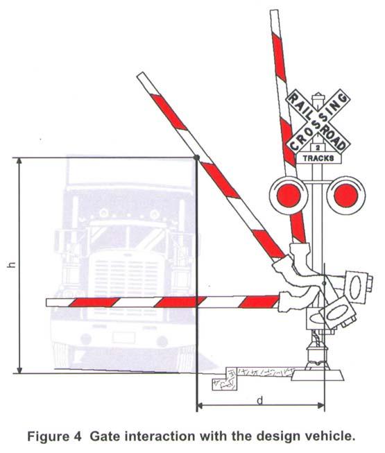
18 Line 55. Time required for design vehicle to clear the descending gates, in seconds, is the sum of the right-of-way transfer time on Line 52, the time required for design vehicle to start moving on Line 53, and the time required for design vehicle to accelerate through the design vehicle length on Line 54. Line 56. Duration of flashing lights before gate descent start, in seconds, is the time the railroad warning lights flash before the gates start to descend. This value typically ranges from 3 to 5 seconds and must be obtained from the railroad. The value obtained from the railroad may be verified using field observation. Line 57. Full gate descent time, in seconds, is the time it takes for the gates to descend to a horizontal position after they start their descent. This value must be obtained from the railroad and may be verified using field observation. In the case where multiple gates descend at different speeds, use the descent time of the gate that reaches the horizontal position first. Line 58. The Proportion of non-interaction gate descent time is the decimal proportion of the full gate descent time on Line 57 during which the gate will not interact with (i.e. not hit) the design vehicle if it is located under the gate. This value depends on the design vehicle height, h, and the distance from the center of the gate mechanism to the nearest side of the design vehicle, d, as shown in Figure 4. Figure 5 can be used to determine the proportion of non-interaction gate descent time. Select the distance from the center of the gate mechanism to the nearest side of the design vehicle, d, on the vertical axis of Figure 5, draw a horizontal line until you reach the curve that represents the design vehicle, and then draw a vertical line down to the horizontal axis and read off the value of the proportion of non-interaction gate descent time. Line 59. Non-interaction gate descent time is time (in seconds) during gate descent that the gate will not interact with (i.e. not hit) the design vehicle if it is located under the gate. In other words, it is the time that expires after the gate starts to descend until it hits the design vehicle if it is located under the gate. This value is calculated by multiplying the full gate descent time on Line 57 with the proportion of non-interaction gate descent time on Line 58.
19
20 Line 60. Time available for design vehicle to clear descending gate, in seconds, is the time, after the railroad warning lights start to flash, that is available for the design vehicle to clear the descending gate before the gate hits the vehicle. It is the sum of the duration of the flashing lights before gate descent start (Line 56) and the non-interaction gate descent time (Line 59). Line 61. Advance preemption time required to avoid design vehicle-gate interaction, in seconds, is calculated by subtracting the time available for the design vehicle to clear descending gate (Line 60) from the time required for the design vehicle to clear descending gate (Line 55). The result is the amount of advance preemption time that is required to avoid the gates descending on a stationary or slow-moving design vehicle. If the result of the subtraction is equal to or less than zero, it means that sufficient time is available, and you should enter zero (0) on Line 61. If the result is greater than the amount of advance preemption time provided by the railroad, as given on Line 36, there is a possibility that the gates could descend on a stationary or slow-moving design vehicle. To avoid this situation, additional advance preemption time should be requested from the railroad. It should be kept in mind that on its own, gates descending on a vehicle is not a critical safety failure, because enough time still exists to clear the crossing before the arrival of the train, if the advance preemption time on Line 36 is provided. Therefore, local policies may vary on whether additional advance preemption time (over and above that on Line 36) should be requested solely for the purpose of prohibiting gates descending on vehicles. If additional advance preemption time is provided to avoid design vehicle-gate interaction, Line 33 of this Worksheet has to updated, and Lines 34 and 35 recomputed. Section 5 also needs to be recomputed to calculate the track clearance green time. REFERENCES This form is being used with the written consent from the Texas Department of Transportation. The following references were used in the development of the 2003 Guide For Determining Time Requirements For Traffic Signal Preemption At Highway-Rail Grade Crossings and these accompanying Instructions. Minnesota Department of Transportation. Minnesota Manual on Uniform Traffic Control Devices(MN MUTCD) On the Internet at Link valid May Institute of Transportation Engineers (ITE). Determining Vehicle Signal Change and Clearance Intervals. An Informational Report prepared by ITE Technical Council Task Force 4TF-1, August 1994.
21 American Association of State Highway & Transportation Officials (AASHTO). A Policy on Geometric Design of Highways and Streets. (Green Book) Marshall, P.S. and W.D. Berg. Design Guidelines for Railroad Preemption at Signalized Intersections. In ITE Journal Volume 67, Number 2, February 1997, pp American Railway Engineering and Maintenance-of-Way Association (AREMA). Manual of Recommended Practices-Signals Engelbrecht, R.J., S. Sunkari, T. Urbanik, and K. Balke. The Preempt Trap: How to Make Sure You do Not Have One. Texas Department of Transportation Project Bulletin , October, On the Internet at reports/ pdf. Link valid May 2003.
GUIDE FOR DETERMINING TIME REQUIREMENTS FOR TRAFFIC SIGNAL PREEMPTION AT HIGHWAY-RAIL GRADE CROSSINGS
 INSTRUCTIONS for the Texas Department of Transportation GUIDE FOR DETERMINING TIME REQUIREMENTS FOR TRAFFIC SIGNAL PREEMPTION AT HIGHWAY-RAIL GRADE CROSSINGS USING THESE INSTRUCTIONS The purpose of these
GUIDE FOR DETERMINING TIME REQUIREMENTS FOR TRAFFIC SIGNAL PREEMPTION AT HIGHWAY-RAIL GRADE CROSSINGS
 INSTRUCTIONS for the Ohio Department of Transportation GUIDE FOR DETERMINING TIME REQUIREMENTS FOR TRAFFIC SIGNAL PREEMPTION AT HIGHWAY-RAIL GRADE CROSSINGS Version DRAFT 11-10-2009 BACKGROUND The Ohio
LADOT Railroad Preemption Form Instructions
 LADOT Railroad Preemption Form Instructions The LADOT Railroad Preemption Form is entirely contained on one worksheet within an Excel workbook. If Additional approaches to the crossing are analyzed, the
Support: The Crossbuck (R15-1) sign assigns right-of-way to rail traffic at a highway-rail grade crossing.
 sign assigns right-of-way to rail traffic at a highway-rail grade crossing.") TECHNICAL COMMITTEE: Railroad and Light Rail Transit Technical Committee DATE OF ACTION: June 25, 2004 TOPIC: Crossbuck with Yield or Stop Signs and Advance Signs. STATUS: Accepted by the National Committee
TECHNICAL COMMITTEE: Railroad and Light Rail Transit Technical Committee DATE OF ACTION: June 25, 2004 TOPIC: Crossbuck with Yield or Stop Signs and Advance Signs. STATUS: Accepted by the National Committee
CHAPTER 9: VEHICULAR ACCESS CONTROL Introduction and Goals Administration Standards
 9.00 Introduction and Goals 9.01 Administration 9.02 Standards 9.1 9.00 INTRODUCTION AND GOALS City streets serve two purposes that are often in conflict moving traffic and accessing property. The higher
PART 8. TRAFFIC CONTROLS FOR HIGHWAY-RAIL GRADE CROSSINGS TABLE OF CONTENTS
 PART 8. TRAFFIC CONTROLS FOR HIGHWAY-RAIL GRADE CROSSINGS TABLE OF CONTENTS CHAPTER 8A. GENERAL Section 8A.01 Introduction... 8A-1 Section 8A.02 Use of Standard Devices, Systems, and Practices... 8A-4
TRAFFIC REGULATION APPROVAL PROCESS
 Approved: Effective: August 22, 2017 Review: June 21, 2017 Office: Traffic Engineering and Operations Topic No.: 750-010-011-e Department of Transportation PURPOSE TRAFFIC REGULATION APPROVAL PROCESS To
SPEED CUSHION POLICY AND INSTALLATION PROCEDURES FOR RESIDENTIAL STREETS
 SPEED CUSHION POLICY AND INSTALLATION PROCEDURES FOR RESIDENTIAL STREETS CITY OF GRAND PRAIRIE TRANSPORTATION SERVICES DEPARTMENT SPEED CUSHION INSTALLATION POLICY A. GENERAL Speed cushions are an effective
Skills and Sequences for In-Car Instruction
 The stopping procedure (shoulder parking) Check the rear view mirror Check the blind spot Right Bring the vehicle towards to the curb at designated point Stop 30 cm away from the curb Once you stop your
AASHTO Policy on Geometric Design of Highways and Streets
 AASHTO Policy on Geometric Design of Highways and Streets 2001 Highlights and Major Changes Since the 1994 Edition Jim Mills, P.E. Roadway Design Office 605 Suwannee Street MS-32 Tallahassee, FL 32399-0450
Scientific Report AN INVESTIGATION OF THE ITE FORMULA AND ITS USE
 Scientific Report AN INVESTIGATION OF THE ITE FORMULA AND ITS USE CP = t + + Abstract This working report is a study of the universally adopted ITE formula which calculates a traffic light s change interval.
American Association of State Highway and Transportation Officials. June Dear Customer:
 American Association of State Highway and Transportation Officials John R. Njord, President Executive Director Utah Department of Transportation John Horsley Executive Director June 2004 Dear Customer:
POLICY FOR THE ESTABLISHMENT AND POSTING OF SPEED LIMITS ON COUNTY AND TOWNSHIP HIGHWAYS WITHIN MCHENRY COUNTY, ILLINOIS
 POLICY FOR THE ESTABLISHMENT AND POSTING OF SPEED LIMITS ON COUNTY AND TOWNSHIP HIGHWAYS WITHIN MCHENRY COUNTY, ILLINOIS MCHENRY COUNTY DIVISION OF TRANSPORTATION 16111 NELSON ROAD WOODSTOCK, IL 60098
Plan Check Policies and Guidelines
 Plan Check Policies and Guidelines VII. A. INTRODUCTION Traffic signing and striping plans are required for all General Plan Roads and any roadway that is 56-foot wide curb-to-curb (78 R/W) or wider. Transportation
RAILROAD PREEMPTION FORMS. Mark Johnson, P.E.
 RAILROAD PREEMPTION FORMS Mark Johnson, P.E. October 12, 2016 The Basic Problem Vehicles stop on tracks Need to interconnect traffic signal with railroad cabinet 2 Preemption Process: ROW Transfer 1 st
A Gap-Based Approach to the Left Turn Signal Warrant. Jeremy R. Chapman, PhD, PE, PTOE Senior Traffic Engineer American Structurepoint, Inc.
 A Gap-Based Approach to the Left Turn Signal Warrant Jeremy R. Chapman, PhD, PE, PTOE Senior Traffic Engineer American Structurepoint, Inc. March 5, 2019 - The problem: Existing signalized intersection
2. ELIGIBILITY REQUIREMENTS
 Speed Hump Policy 1. GENERAL The purpose of this policy is to provide guidelines for the application of speed humps. A "speed hump" is a gradual rise and fall of pavement surface across the width of the
Vista Municipal Code
 Section 16.57.050 Private streets prohibited in certain zones. No lots zoned for multi-family, commercial, or industrial uses may be created using private street easements for access, except as provided
Recommendations for AASHTO Superelevation Design
 Recommendations for AASHTO Superelevation Design September, 2003 Prepared by: Design Quality Assurance Bureau NYSDOT TABLE OF CONTENTS Contents Page INTRODUCTION...1 OVERVIEW AND COMPARISON...1 Fundamentals...1
 اجزا ء سیست م اهی ح م ل و نق ل http://mnooriamiri.professora.ir Road users-drivers, pedestrians, bicyclists, passengers Vehicles- private and commercial Streets and highways Traffic control devices The
TRAFFIC CALMING PROGRAM
 TRAFFIC CALMING PROGRAM PROGRAM BASICS Mount Pleasant Transportation Department 100 Ann Edwards Lane Mt. Pleasant, SC 29465 Tel: 843-856-3080 www.tompsc.com The Town of Mount Pleasant has adopted a traffic
The purpose of this lab is to explore the timing and termination of a phase for the cross street approach of an isolated intersection.
 1 The purpose of this lab is to explore the timing and termination of a phase for the cross street approach of an isolated intersection. Two learning objectives for this lab. We will proceed over the remainder
Access Management Standards
 Access Management Standards This section replaces Access Control Standards on Page number 300-4 of the Engineering Standards passed February 11, 2002 and is an abridged version of the Access Management
CHAPTER 71: TRAFFIC REGULATIONS
 Section CHAPTER 71: TRAFFIC REGULATIONS General Provisions 71.01 Restrictions on direction of travel 71.02 Right-of-way; stop and yield signs 71.03 Interference with traffic control devices or railroad
TITLE 16. TRANSPORTATION CHAPTER 27. TRAFFIC REGULATIONS AND TRAFFIC CONTROL DEVICES
 NOTE: This is a courtesy copy of this rule. The official version can be found in the New Jersey Administrative Code. Should there be any discrepancies between this text and the official version, the official
TRAFFIC MANAGEMENT STANDARDS CITY OF GARLAND TRANSPORTATION DEPARTMENT
 TRAFFIC MANAGEMENT STANDARDS CITY OF GARLAND TRANSPORTATION DEPARTMENT JUNE 1996 TABLE OF CONTENTS 1.0 Street Design Standards 1.1 Right-of-Way Requirements 1.2 Median Openings 1.3 Sidewalks 1.4 Traffic
Created by: St. Louis County
 Created by: Victor Lund, PE Traffic Engineer St. Louis County Ken Johnson, PE, PTOE State WZ, etc. MnDOT Why do workers want speed limits? How effective are speed limits in work zones? New legislation
Section 2B.59 Weight Limit Signs - Interim Revisions
 Note: this document is an interim modification to Section 2B.59 of the Virginia Supplement to the MUTCD, Revision #1. Once the VDOT District Structure & Bridge section has made the determination that a
Traffic Engineering Study
 Traffic Engineering Study Bellaire Boulevard Prepared For: International Management District Technical Services, Inc. Texas Registered Engineering Firm F-3580 November 2009 Executive Summary has been requested
AFFECTED SECTIONS OF MUTCD: Section 2C.36 Advance Traffic Control Signs Table 2C-4. Guidelines for Advance Placement of Warning Signs
 1 2 3 4 5 6 7 8 9 10 11 12 13 14 15 16 17 18 19 20 21 22 23 24 25 26 27 28 29 30 31 32 33 34 35 36 37 38 39 RWSTC June 2012 RW # 3 TOPIC: Advance Traffic Control Signs TECHNICAL COMMITTEE: Regulatory &
DIVISION V SURFACINGS AND PAVEMENTS
 36-3.01 GENERAL DIVISION V SURFACINGS AND PAVEMENTS 36 GENERAL 04-20-18 Replace section 36-3 with: 36-3 PAVEMENT SMOOTHNESS 36-3.01A Summary Section 36-3 includes specifications for measuring the smoothness
3.15 SAFETY AND SECURITY
 3.15 SAFETY AND SECURITY Introduction This section describes the environmental setting and potential effects of the alternatives analyzed in this EIR with regard to safety and security in the SantaClara-Alum
Helping Autonomous Vehicles at Signalized Intersections. Ousama Shebeeb, P. Eng. Traffic Signals Engineer. Ministry of Transportation of Ontario
 Helping Autonomous Vehicles at Signalized Intersections Ousama Shebeeb, P. Eng. Traffic Signals Engineer Ministry of Transportation of Ontario Paper Prepared for Presentation At the NEXT GENERATION TRANSPORTATION
Isaac Newton vs. Red Light Cameras
 2012 Isaac Newton vs. Red Light Cameras Approach Speed vs. Speed Limit Brian Cecvehicleelli redlightrobber.com 3/1/2012 Table of Contents Approach Speed vs. Speed Limit... 3 Definition of Speed Limit...
Introduction. 3. The sample calculations used throughout this paper are based on a roadway posted at 35 mph.
 Calculating a Legally Enforceable Yellow Change Interval For Turning Lanes in California by Jay Beeber, Executive Director, Safer Streets L.A., Member ITE and J. J. Bahen, Jr., P.E., Life Member National
Load Rating for SHVs and EVs
 Load Rating for SHVs and EVs and Other Challenges Lubin Gao, Ph.D., P.E. Senior Bridge Engineer Load Rating Office of Bridges and Structures Federal Highway Administration Outline Introduction Specialized
POLICY AND PROCEDURE FOR SPEED HUMP INSTALLATION. Effective Date: July 10, 2013
 CITY OF MORENO VALLEY DEPARTMENT OF PUBLIC WORKS TRANSPORTATION ENGINEERING DIVISION Administration Policy #A-14A POLICY AND PROCEDURE FOR SPEED HUMP INSTALLATION Effective Date: July 10, 2013 Approved
CHAPTER 11 SNOWMOBILES AND ALL-TERRAIN VEHICLES SNOWMOBILE AND ALL-TERRAIN VEHICLE REGULATIONS
 241 CHAPTER 11 SNOWMOBILES AND ALL-TERRAIN VEHICLES 11.001 INTENT The City of Cornell, Chippewa County adopts the following Ordinance to regulate the use of snowmobiles and all-terrain vehicles and to
RE: A Traffic Impact Statement for a proposed development on Quinpool Road
 James J. Copeland, P.Eng. GRIFFIN transportation group inc. 30 Bonny View Drive Fall River, NS B2T 1R2 May 31, 2018 Ellen O Hara, P.Eng. Project Engineer DesignPoint Engineering & Surveying Ltd. 200 Waterfront
Plan Check Policies and Guidelines
 VIII. TRAFFIC SIGNING AND STRIPING PLANS A. INTRODUCTION Traffic signing and striping plans are required for all General Plan Roads and any roadway that is 56-foot wide curb-to-curb (78 R/W) or wider.
Appendix J Traffic Impact Study
 MRI May 2012 Appendix J Traffic Impact Study Level 2 Traffic Assessment Limited Impact Review Appendix J [This page was left blank intentionally.] www.sgm-inc.com Figure 1. Site Driveway and Trail Crossing
TRAFFIC ENGINEERING DIVISION INSTRUCTIONAL & INFORMATIONAL MEMORANDUM
 VIRGINIA DEPARTMENT OF TRANSPORTATION TRAFFIC ENGINEERING DIVISION INSTRUCTIONAL & INFORMATIONAL MEMORANDUM GENERAL SUBJECT: Portable Temporary Rumble Strips (PTRS) SPECIFIC SUBJECT: Guidelines for the
Memorandum. To: Sue Polka, City Engineer, City of Arden Hills. From: Sean Delmore, PE, PTOE. Date: June 21, 2017
 Memorandum engineering planning environmental construction 701 Xenia Avenue South Suite 300 Minneapolis, MN 55416 Tel: 763-541-4800 Fax: 763-541-1700 To: Sue Polka, City Engineer, City of Arden Hills From:
(Refer Slide Time: 00:01:10min)
") Introduction to Transportation Engineering Dr. Bhargab Maitra Department of Civil Engineering Indian Institute of Technology, Kharagpur Lecture - 11 Overtaking, Intermediate and Headlight Sight Distances
Introduction to Transportation Engineering Dr. Bhargab Maitra Department of Civil Engineering Indian Institute of Technology, Kharagpur Lecture - 11 Overtaking, Intermediate and Headlight Sight Distances
CHAPTER 4 SNOWMOBILES. The Commissioner of Conservation acting directly or through his/her authorized agent.
 6-4-1 6-4-1 CHAPTER 4 SNOWMOBILES SECTION: 6-4-1: Definitions 6-4-2: General Operating Requirements And Restrictions 6-4-3: Crossing Roadways, Streets And Thoroughfares 6-4-4: Persons Under Eighteen Years
Alberta Infrastructure HIGHWAY GEOMETRIC DESIGN GUIDE AUGUST 1999
 &+$37(5Ã)Ã Alberta Infrastructure HIGHWAY GEOMETRIC DESIGN GUIDE AUGUST 1999 &+$37(5) 52$'6,'()$&,/,7,(6 7$%/(2)&217(176 Section Subject Page Number Page Date F.1 VEHICLE INSPECTION STATIONS... F-3 April
M I D - C O A S T REGIONAL PLANNING COMMISSION 166 SOUTH MAIN STREET, SUITE 201 ROCKLAND, ME (207)
") M I D - C O A S T REGIONAL PLANNING COMMISSION 166 SOUTH MAIN STREET, SUITE 201 ROCKLAND, ME 04841 (207) 594-2299 Appropriate access management of municipal roadways can enhance safety, maintain roadway
M I D - C O A S T REGIONAL PLANNING COMMISSION 166 SOUTH MAIN STREET, SUITE 201 ROCKLAND, ME 04841 (207) 594-2299 Appropriate access management of municipal roadways can enhance safety, maintain roadway
CONTENTS I. INTRODUCTION... 2 II. SPEED HUMP INSTALLATION POLICY... 3 III. SPEED HUMP INSTALLATION PROCEDURE... 7 APPENDIX A... 9 APPENDIX B...
 Speed Hump Program CONTENTS I. INTRODUCTION... 2 II. SPEED HUMP INSTALLATION POLICY... 3 1. GENERAL... 3 2. ELIGIBILITY REQUIREMENTS... 3 A. PETITION... 3 B. OPERATIONAL AND GEOMETRIC CHARACTERISTICS OF
ALLEGAN COUNTY ROAD COMMISSION. Adopted by the Board of County Road Commissioners, December 28, Sign Policy
 ALLEGAN COUNTY ROAD COMMISSION Adopted by the Board of County Road Commissioners, December 28, 2016 Sign Policy Common/Policies/Sign Policy 2016 TABLE OF CONTENTS Page I. Purpose and Background.................................
JCE4600 Fundamentals of Traffic Engineering
 JCE4600 Fundamentals of Traffic Engineering Introduction to Geometric Design Agenda Kinematics Human Factors Stopping Sight Distance Cornering Intersection Design Cross Sections 1 AASHTO Green Book Kinematics
Chapter III Geometric design of Highways. Tewodros N.
 Chapter III Geometric design of Highways Tewodros N. www.tnigatu.wordpress.com tedynihe@gmail.com Introduction Appropriate Geometric Standards Design Controls and Criteria Design Class Sight Distance Design
Simulating Trucks in CORSIM
 Simulating Trucks in CORSIM Minnesota Department of Transportation September 13, 2004 Simulating Trucks in CORSIM. Table of Contents 1.0 Overview... 3 2.0 Acquiring Truck Count Information... 5 3.0 Data
Isaac Newton vs. Red Light Cameras
 2012 Isaac Newton vs. Red Light Cameras Problems with the ITE Kinematic Formula for Yellow Light Intervals in a Nutshell Brian Ceccarelli redlightrobber.com 2/15/2012 Table of Contents Problem... 3 ITE
Mr. Kyle Zimmerman, PE, CFM, PTOE County Engineer
 Los Alamos County Engineering Division 1925 Trinity Drive, Suite B Los Alamos, NM 87544 Attention: County Engineer Dear Kyle: Re: NM 502 Transportation Corridor Study and Plan Peer Review Los Alamos, New
EMERGENCY ACCESS POLICY
 Cowlitz 2 Fire & Rescue Policies and Operating Guidelines Policy: EMERGENCY ACCESS POLICY Number Effective Date Approved and Issued: 4001 8/28/02 8/28/02 1.0 REFERENCE 23 CFR Part 650 Subpart C Code of
SPEARFISH FIRE DEPARTMENT POLICIES AND PROCEDURES
 SPEARFISH FIRE DEPARTMENT POLICIES AND PROCEDURES Page 1 of 8 Volume: Operations Section: 20.00 Number: 20.06 Subject: Emergency & Private Vehicle Operations & Driver Requirements Date Issued: 13 march
STATE OF OHIO DEPARTMENT OF TRANSPORTATION SUPPLEMENTAL SPECIFICATION 808 DIGITAL SPEED LIMIT (DSL) SIGN ASSEMBLY.
 SIGN ASSEMBLY.") 808.01 Description 808.02 Materials 808.03 Design Speed 808.04 Construction 808.05 Method of Measurement 808.06 Basis of Payment STATE OF OHIO DEPARTMENT OF TRANSPORTATION SUPPLEMENTAL SPECIFICATION 808
808.01 Description 808.02 Materials 808.03 Design Speed 808.04 Construction 808.05 Method of Measurement 808.06 Basis of Payment STATE OF OHIO DEPARTMENT OF TRANSPORTATION SUPPLEMENTAL SPECIFICATION 808
800 Access Control, R/W Use Permits and Drive Design
 Table of Contents 801 Access Control... 8-1 801.1 Access Control Directives... 8-1 801.2 Access Control Policies... 8-1 801.2.1 Interstate Limited Access... 8-1 801.2.2 Limited Access... 8-1 801.2.3 Controlled
NAU DESIGN GUIDELINES FOR DISABLED ACCESS PARKING AND ACCESSIBLE ROUTE AT VEHICULAR TRAFFIC AREAS
 NAU DESIGN GUIDELINES FOR DISABLED ACCESS PARKING AND ACCESSIBLE ROUTE AT Intent, Purpose And Goals: The intent and purpose of these NAU technical requirements is to establish minimum requirements to safeguard
FREQUENTLY ASKED QUESTIONS
 THE PROJECT Last updated on 2/19/16 FREQUENTLY ASKED QUESTIONS What s happening on Highway 169? The Minnesota Department of Transportation (MnDOT) is planning to rebuild and repair the infrastructure on
Date: February 7, 2017 John Doyle, Z-Best Products Robert Del Rio. T.E. Z-Best Traffic Operations and Site Access Analysis
 Memorandum Date: February 7, 07 To: From: Subject: John Doyle, Z-Best Products Robert Del Rio. T.E. Z-Best Traffic Operations and Site Access Analysis Introduction Hexagon Transportation Consultants, Inc.
Chapter 17 TRAFFIC AND VEHICLES. Adoption of Uniform Rules of the Road. Temporary Traffic Regulations.
 Chapter 17 TRAFFIC AND VEHICLES Article I. Article II. Article III. In General. Section 17.1 Adoption of Uniform Rules of the Road. Section 17.2 Temporary Traffic Regulations. Section 17.3 Traffic Speed,
STATE OF FLORIDA Department of Highway Safety and Motor Vehicles SECTION: SUBJECT: PAGE: 4-A UNIFORM TRAFFIC CITATION 1 OF 8 PROCEDURES FOR COMPLETION
 4-A UNIFORM TRAFFIC CITATION 1 OF 8 1. COMPLETION OF UNIFORM TRAFFIC CITATION (Illustration on PAGE: 8 of this section) Make sure that a hard divider is used between the sets (four copies) when completing
East Lake Tarpon Special Fire Control District
 East Lake Tarpon Special Fire Control District Implementation Date: 11/2000 Forms or Attachments: None SOP 803 Vehicle Safety Revision Date(s): 07/2004 Reviewed Date(s): A. All operators of Departmental
Virginia Department of Education
 Virginia Department of Education Module Three Transparencies Basic Maneuvering Tasks: Low Risk Environment Topic 1 -- Basic Maneuvers Topic 2 -- Vision and Perception Topic 3 -- Controlling Risk Using
SECTION: 1503 Use of Lights & Sirens SUPERCEDES/RESCINDS: All Prior EFFECTIVE DATE:
 SECTION: 1503 TITLE: Use of Lights & Sirens SUPERCEDES/RESCINDS: All Prior EFFECTIVE DATE: 05-01-2014 1. DEFINITIONS 1. TRUE EMERGENCY: A situation in which there is a high probability of death, serious
Log Compliance Information
 Log Compliance Information The following information is being provided to assure you understand that the Hours of Service and Log Compliance rules are required for all interstate drivers according to the
CHAPTER 14 TRAFFIC CODE THE MINNESOTA HIGHWAY TRAFFIC REGULATION ACT.
 CHAPTER 14 TRAFFIC CODE 14.01 THE MINNESOTA HIGHWAY TRAFFIC REGULATION ACT. 1. Adoption. The City hereby adopts the Minnesota Highway Traffic Regulation Act as set forth in Minnesota Statutes, Chapter
Sight Distance. A fundamental principle of good design is that
 Session 9 Jack Broz, PE, HR Green May 5-7, 2010 Sight Distance A fundamental principle of good design is that the alignment and cross section should provide adequate sight lines for drivers operating their
Section 6H.01 Typical Applications
 December 27, 2010 Draft Page 6H-1 Section 6H.01 Typical Applications Support: 01 Whenever the acronym TTC is used in this Chapter, it refers to temporary traffic control. 02 The needs and control of all
2.3. Priority Responses recognized by the Derby Fire Department will be as follows:
 Release: 1.0 Effective: Draft Derby Fire Department Standard Operating Procedure Number 20 Operation of Emergency Apparatus 1. Purpose 1.1 The purpose of this procedure is to establish guidelines for the
Study on System Dynamics of Long and Heavy-Haul Train
 Copyright c 2008 ICCES ICCES, vol.7, no.4, pp.173-180 Study on System Dynamics of Long and Heavy-Haul Train Weihua Zhang 1, Guangrong Tian and Maoru Chi The long and heavy-haul train transportation has
ARTICLE 15 PARKING AND LOADING REQUIREMENTS
 ARTICLE 15 PARKING AND LOADING REQUIREMENTS SECTION 15.01 OFF-STREET PARKING REQUIREMENT There shall be provided in all districts at the time of erection or enlargement of any main building or structure,
PURPOSE POLICY. Page 1 of 6 / S.O.G Highway Operations Pascal Arnes Chief of Fire
 DECATUR TOWNSHIP FIRE DEPARTMENT STANDARD OPERATING GUIDELINE TITLE: HIGHWAY OPERATIONS SECTION: SAFETY NUMBER: 6.01 EFFECTIVE: JULY 1, 2014 THIS GUIDELINE SUPERSEDES ALL PREVIOUS GENERAL ORDERS, POLICIES,
Pedestrian Autonomous Emergency Braking Test Protocol (Version II) February 2019
 February 2019") Pedestrian Autonomous Emergency Braking Test Protocol (Version II) February 2019 Contents DOCUMENT REVISION HISTORY... ii SUMMARY... 1 TEST ENVIRONMENT... 2 Surface and Markings... 2 Surroundings... 2
Pedestrian Autonomous Emergency Braking Test Protocol (Version II) February 2019 Contents DOCUMENT REVISION HISTORY... ii SUMMARY... 1 TEST ENVIRONMENT... 2 Surface and Markings... 2 Surroundings... 2
CHAPTER 9 PARKING REGULATIONS (SEE CHAPTER 7 FOR DEFINITIONS, SCOPE AND APPLICATION RELATING TO THIS CHAPTER)
") CHAPTER 9 PARKING REGULATIONS (SEE CHAPTER 7 FOR DEFINITIONS, SCOPE AND APPLICATION RELATING TO THIS CHAPTER) SECTION 9.01. PRESUMPTION. As to any vehicle parking in violation of Chapters 7, 8 and 9 when
CHAPTER 9 PARKING REGULATIONS (SEE CHAPTER 7 FOR DEFINITIONS, SCOPE AND APPLICATION RELATING TO THIS CHAPTER) SECTION 9.01. PRESUMPTION. As to any vehicle parking in violation of Chapters 7, 8 and 9 when
Designation of a Community Safety Zone in Honey Harbour in the Township of Georgian Bay
 TO: FROM: Chair and Members Engineering and Public Works Committee Mark Misko, C.E.T. Manager, Roads Maintenance and Construction DATE: March 23, 2016 SUBJECT: REPORT NO: Designation of a Community Safety
MEMORANDUM. Figure 1. Roundabout Interchange under Alternative D
 MEMORANDUM Date: To: Liz Diamond, Dokken Engineering From: Subject: Dave Stanek, Fehr & Peers Western Placerville Interchanges 2045 Analysis RS08-2639 Fehr & Peers has completed a transportation analysis
FREQUENTLY ASKED QUESTIONS
 THE PROJECT Last updated on 9/8/16 FREQUENTLY ASKED QUESTIONS What s happening on Highway 169? The Minnesota Department of Transportation (MnDOT) is planning to rebuild and repair the infrastructure on
Transit City Etobicoke - Finch West LRT
 Delcan Corporation Transit City Etobicoke - Finch West LRT APPENDIX D Microsimulation Traffic Modeling Report March 2010 March 2010 Appendix D CONTENTS 1.0 STUDY CONTEXT... 2 Figure 1 Study Limits... 2
Spot Speed Study. Engineering H191. Autumn, Hannah Zierden, Seat 20. Ryan King, Seat 29. Jae Lee, Seat 23. Alex Rector, Seat 26
 Spot Speed Study Engineering H191 Autumn, 2011 Hannah Zierden, Seat 20 Ryan King, Seat 29 Jae Lee, Seat 23 Alex Rector, Seat 26 Instructor: Dr. Kathy Harper Class Section: 1:30 Lab Section: Thursday, 1:30-3:18
2. Under what condition is it unlawful to permit another person to drive your vehicle?
 Lynden Bellingham Mt Baker HS Blaine HS Meridian HS Nooksack HS Driver Guide Review Nelson Driving School, LLC www.nelsondrivingschool.com (360) 756-8777 2300 James St, Suite 103 Bellingham WA 98225 Directions:
DISTRIBUTION: Electronic Recipients List TRANSMITTAL LETTER NO. (15-01) MINNESOTA DEPARTMENT OF TRANSPORTATION. MANUAL: Road Design English Manual
 MINNESOTA DEPARTMENT OF TRANSPORTATION. MANUAL: Road Design English Manual") DISTRIBUTION: Electronic Recipients List MINNESOTA DEPARTMENT OF TRANSPORTATION DEVELOPED BY: Design Standards Unit ISSUED BY: Office of Project Management and Technical Support TRANSMITTAL LETTER NO.
DISTRIBUTION: Electronic Recipients List MINNESOTA DEPARTMENT OF TRANSPORTATION DEVELOPED BY: Design Standards Unit ISSUED BY: Office of Project Management and Technical Support TRANSMITTAL LETTER NO.
CHAPTER 2 ZONING AND DEVELOPMENT
 2.200 GENERAL DEVELOPMENT STANDARDS CHAPTER 2 ZONING AND DEVELOPMENT Section 2.201 GENERAL PROVISIONS... 2.2-1 Section 2.202 FENCES AND VISIONS CLEARANCE... 2.2-2 2.202.01 Fences... 2.2-2 2.202.02 Vision
Design Vehicles Over-Length Configurations
 Subject: Design Vehicles Over-Length Configurations Date: September 30, 2015 Author: Darwin Tyacke, AScT Bulletin Number: Action Required: Immediate Bulletin Type: Informational Effective Date: September
STATE OF RHODE ISLAND
 LC00 00 -- H STATE OF RHODE ISLAND IN GENERAL ASSEMBLY JANUARY SESSION, A.D. 00 A N A C T RELATING TO MOTOR VEHICLES -- EMERGENCY VEHICLES Introduced By: Representatives Shanley, Lally, San Bento, Jacquard,
STOPPING SIGHT DISTANCE AS A MINIMUM CRITERION FOR APPROACH SPACING
 STOPPING SIGHT DISTANCE AS A MINIMUM CRITERION prepared for Oregon Department of Transportation Salem, Oregon by the Transportation Research Institute Oregon State University Corvallis, Oregon 97331-4304
Applicable California Vehicle Code Sections, 2015 Edition
 Applicable California Vehicle Code Sections, 2015 Edition Speed limits in California are governed by the California Vehicle Code (CVC), Sections 22348 through 22413; also, pertinent sections are found
Brownwood Portable Traffic Signals and AFADs Evaluation. Carl Johnson, P.E., TxDOT Brownwood District Melisa Finley, P.E., TTI
 Brownwood Portable Traffic Signals and AFADs Evaluation Carl Johnson, P.E., TxDOT Brownwood District Melisa Finley, P.E., TTI Using Portable Traffic Signals (PTS) in Maintenance Operations: Brownwood District
Conventional Approach
 Session 6 Jack Broz, PE, HR Green May 5-7, 2010 Conventional Approach Classification required by Federal law General Categories: Arterial Collector Local 6-1 Functional Classifications Changing Road Classification
b. take a motorcycle-riding course taught by a certified instructor.
 Chapter 08 - Practice Questions Multiple Choice Identify the letter of the choice that best completes the statement or answers the question. 1) Why should you stay out of the open space to the right of
Overview. Prioritization of Safety Strategies Development of the Minnesota Sinusoidal Rumble Strip Implementation and Public Relations Considerations
 Victor Lund, PE, Traffic Engineer St. Louis County, Minnesota October 11, 2018 Overview Prioritization of Safety Strategies Development of the Minnesota Sinusoidal Rumble Strip Implementation and Public
1 of 8 6/20/12 12:10 PM
 HOME PROPERTY PARKING & VEHICLES Camera Violations Commercial Programs Diplomats/Consular Manhattan Residents Parking Tickets Refunds Towed Vehicles BUSINESS/EXCISE TAXES OTHER SERVICES FORMS & PUBLICATIONS
Memorandum Federal Highway Administration
 Memorandum Federal Highway Administration ELECTRONIC MAIL Subject: INFORMATION: Optional Use of Acknowledgment Date: August 10, 2005 Signs on Highway Rights-of-Way Original signed by From: J. Richard Capka
STOPPING, STANDING OR PARKING PROHIBITED
 CHAPTER 355: STOPPING, STANDING OR PARKING PROHIBITED IN SPECIFIED PLACES SECTION 355.010: STOPPING, STANDING OR PARKING PROHIBITED A. Except when necessary to avoid conflict with other traffic, or in
TRAFFIC PARKING ANALYSIS
 TRAFFIC PARKING ANALYSIS NAPA FLEA MARKET COUNTY OF NAPA Prepared for: Tom Harding Napa-Vallejo Flea Market 33 Kelly Road American Canyon, CA 9453 Prepared by: 166 Olympic Boulevard, Suite 21 Walnut Creek,
ARTICLE 8 OFF-STREET PARKING AND PRIVATE DRIVEWAY STANDARDS
 ARTICLE 8 OFF-STREET PARKING AND PRIVATE DRIVEWAY STANDARDS TABLE OF CONTENTS SECTION PAGE 8.1 GENERAL STANDARDS...8-2 8.2 PRIVATE DRIVEWAY PROVISIONS...8-4 8.3 OFF-STREET PARKING STANDARDS...8-5 8.4 OFF-STREET
2016 State Roadeo Written Test. Name: District:
 2016 State Roadeo Written Test Name: District: PURPOSE OF TEST: The purpose of this test is to showcase the knowledge of the contestant and promote education of more in-depth knowledge which pertains to
RTE. 1 at RTE. 637 & RTE. 639
 INTERSECTION SAFETY STUDY Prepared for: Virginia Department of Transportation Central Region Operations Traffic Engineering (UPC #81378, TO 12-092) DAVENPORT Project Number: 13-368 / /2014 RTE. 1 at RTE.
DESCRIPTION This work consists of measuring the smoothness of the final concrete or bituminous surface.
 2399 PAVEMENT SURFACE SMOOTHNESS 2399.1 DESCRIPTION This work consists of measuring the smoothness of the final concrete or bituminous surface. A Definitions The Department defines Smoothness as the Mean