Team 1378 X ED. Hilo Viking Robotics. Engineering Notebook. Team Roster:
|
|
|
- Garey Randall
- 5 years ago
- Views:
Transcription
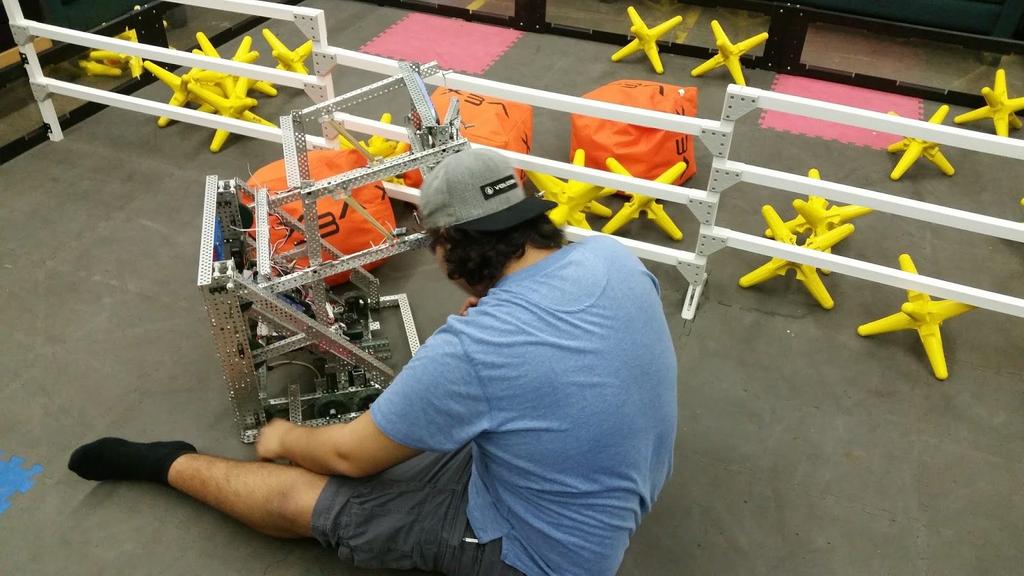
1 Hilo Viking Robotics Team 1378 X ED Engineering Notebook Team Roster: Brandon Leasure Dennis Palad Dustin De Reis Joshua Wilson Yuma Long Hua Uehara Joel Paye Kenji Emerson
2 1
3 Table of Contents Section Page Introduction 4 Design 7 Process 7 Application of Process 8 Game Analysis 9 Game Overview 9 Manual and Rules Analysis 10 Vex Season Records 11 Vex Kickoff 11 ITERATION 1 12 ITERATION 2 37 ITERATION 3 42 ITERATION 4 47 ITERATION 5 55 ITERATION 6 56 Reveal 58 Building 58 Process 58 Program 58 Initial Program Goals 58 Initial Program 58 Final Program 61 2
4 Tele-op Description 73 Autonomous Description 73 XED Statistics 74 Statistics Calculations 78 Budget 79 Conclusion 80 References 81 3

5 Introduction Hilo Viking Robotics Team 1378, HVR, Hilo Viking Robotics, these are some of the many names or titles the Hilo High School robotics team goes by. Hilo Viking Robotics does a multitude of things, ranging from competing in Vex and FIRST competitions. to mentoring our own Camp Eureka. HVR is proud of being a completely student driven club, this means that our members are the leaders. Our missions include spreading STEM throughout the community and helping our members to make their own unique mark on the world. Vex robotics competition is one of HVR s more prioritized aspect of robotics. We focus on Vex as it is very useful in gaining and developing skills. Since Vex is on a small scale it can be used to teach engineering concepts and principles. Hilo Viking Robotics has excelled at these competitions, last year [ ] HVR was one of the Champion alliances for all of the competitions on the Big Island. In another previous year [ ] HVR was able to compete at the world level competition for the game Sack Attack. 4
6 Team X ED Team XED consists of 5 members and 3 dedicated coaches. The team captain is Joshua Wilson. Josh is the main builder of the team, and has had 4 years of vex experience previous to this year building robots to compete. He has spent countless hours designing mechanisms, and improving them. He realizes that anyone can make a robot, but only the teams who make the best robots move on to higher levels of competitions. Dennis Palad is the team's main programmer. Dennis is Team XED s former team captain. He participated in last years game Nothing But Net and has many ideas as to how to be an effective leader. The reasoning behind this is because he has paid attention to the leaders of the teams last year and took notes on what they did good and how they could have improved. Dennis wishes to leave a lasting impression on the members of this club Next would be Yuma Long who has not had that much experience with robotics. This is his second year in robotics but is more focused on other aspects of robotics, mainly cinematography. Yuma has grown to encourage and develop the skills of cinematography with many of the members. He especially developed the skills of Emily Kerr, Milan Ragasa, and Elizabeth Atkinson, these three have already produced a high quality video that gives on overview of the July Summer Camp Eureka of Then we have Dustin de Reis who is specialized in building. This Vex season will be Dustin s third year participating in such events and competitions. Next is Brandon Leasure. He is focused on programming, and has had most experience with general programming and programming arduinos. Most of his experience is with the programming language C++. This is going to be Brandon s third year participating in robotics. Team XED s dedicated mentors are Joel Paye, Kenji Emerson, and Hua Uehara. They are all graduates from Hilo High School, class of 2016, and are Hilo Viking Robotics Alumni. At the end of their year they helped Team XED design wise. Joel Paye is a former head programmer for Hilo Viking Robotics. Joel is also very knowledgeable about engineering, design, and programming for Vex. Kenji, on the other hand, is very knowledgeable about the general engineering principles and mathematics. Kenji is particularly helpful when we need guidance on the execution of a mechanism. Hua specializes in CAD and design. Hua also has knowledge on the other fundamentals, including programming and building. Each mentor has something to give to the team, 5
7 and even if they provide the same knowledge, they each have an interpretation that our team members can take something from. The really nice thing about our mentors is that we have all been working side by side with them for the last year or two. They are our friends, and our former club members. This makes it that much easier to communicate as student and mentor. 6

8 Process Design The Engineering Process is one that allows for iteration and development. The engineering process requires copious amounts of trial and error and innovation. Since the process is dependent on innovation and iteration, the best outcome will come with the most thought out and thorough solutions. Eight steps, with an optional step, are included within the process. Starting with the identification of the need or problem. This first step will be the one to initialize the process, although a fairly simple step it is crucial to know what is needed. After identifying and understanding what is needed it will be imperative to research 7
9 the constraints of that need, whether it be size, shape, material, etc. With the knowledge obtained from research, start brainstorming possible solutions to the situation. Next will be to evaluate all possible solutions and pick the best one. Make this solution reality and start to prototype it. Once prototyping is finished test the prototype, depending on the results of the prototype,present the final solution to the problem. Depending on the result of the process, redesign and redo the whole process to get a better result. Application of Process This process is applied to the many things that Hilo Viking Robotics does as a club. Team XED uses this process to iterate and continue to improve upon the design of our robot for Vex Starstruck Throughout every single step of working on the robot this was used. In the beginning of the season, during kickoff, the team first sat down and discussed what was needed from a robot to perform well during competitions. We identified the rules of the game and the constraints of the robot. With this information we were able to brainstorm the possible designs for Starstruck. The initial designs our team had brainstormed were an H-drive, a catapult, and a fully mechanical hanger, or an H-drive with a caucasus beetle manipulator. From here we decided to look at these designs and pick the best one, we chose the catapult. We then went on to building the robot and redesigning it. This process repeated over and over again to come out with the best design for Vex Starstruck

10 Game Overview Game Analysis The Vex Starstruck field is a square separated by a 24 tall fence throughout the center, in which robots reside on either side. The scoring objects are found on either side as well as resting on the fence itself. The scoring objects are composed of stars and cubes. There are two scoring zones, a near and far zone. The near zone encompasses the half of the field closest to the fence, while the far zone encompasses the half of the field closest to the field perimeter parallel to the fence. One point is gained if a star is scored in the near zone of the opposing team, and two points are gained if a cube is scored in the near zone. Scoring in the far zone with either scoring object will double its score, thus two points are gained if a star is scored in the far zone, and four points are gained if a cube is scored. There is another method of scoring, which includes hanging on the hanging bar, which is a 30 high vertical PVC pipe, found in the corner of the field on either side of the fence. Hanging a robot on a pipe of its own color at the end of a match will reward the team with a low hang : The robot is hanging on the pole and completely above the field tiles. Alternatively, a team can also be rewarded a high hang : The robot is touching the pole of its own color as well as completely above the field perimeter wall (12 ). The default scoring object configuration at the beginning of every match is as follows: 10 stars resting on the fence (three on either high sections, and four in the middle), one star in each corner of the field (two on each side), three stars in the two closest middle tiles of the perimeter parallel to the fence (on either side of the field), and one cube in the middle of each field half separated by the fence. 9
11 Manual and Rules Analysis At the beginning of a match, a robot may only be placed on an Alliance Starting Tile (colored red or blue, depending on alliance), and may not touch any other tiles, or another robot. Each robot is allowed one preload star scoring object. The preload is legal if it is touching the robot, not touching any other tiles beside the AST, and is fully within the field perimeter. During the driver control period, student drive team members may handle their robot in specific ways if no part of the robot has moved at all during the match. A member of the student drive team may turn the robot off and on, plug in a battery or power expander, plug in a VEXnet key, or turn the power expander on and off. Each team must introduce a driver control load (cube) in between the 30 and 0 seconds remaining period of the match. The cube must be placed gently onto the robot while it is touching the AST, if the cube is not placed onto the robot, it is to be placed onto the AST and not exceed the boundary of the tile. If the driver control load is not introduced legally, the cube s points will go to the opposing alliance as if it was scored in their far zone. Drive team members are not allowed to crush or compress preloads or driver control loads. Teams are to not have their robot ever make contact with the tiles opposite their side of the field. Using strategies that intentionally cause an opposing team to break a rule, as well as using strategies that include latching, grabbing, or grasping a field element will not be tolerated. Fouls that occur within the autonomous period that change the outcome of the autonomous bonus, and not the match, will be allowed, however the autonomous bonus will be awarded to the opposing alliance. 10
12 Vex Season Records VEX STARSTRUCK KICKOFF - 4/23/2016 [Saturday]: Summary: Today is the first meeting after the release of this year s game, Vex Starstruck. Team 1378 XED discussed quite a bit about the game and the most effective way to score and plans to win. We brainstormed many ideas, starting with Yuma Long s innovative idea that took inspiration from the caucasus beetle. This design would utilize 3 attachments, two side horns and one middle horn. The basic concept is to grab the scoring objects with the 2 side horns and hold it there while the middle horn launches the objects. There was no specific drivetrain necessary to build this robot. This design did not really have a viable way of hanging and, from our knowledge, has not been tested before and is risky. Another design idea was a kicker on a lift, The kicker would take scoring objects by scooping them off of the field using a spatula-like plate. This robot would also have a 4 wheel mecanum drive. The final design was a robot with mechanisms from other successful robots. First is a scooping and launching mechanism made by one of our own Hilo Viking Robotics teams from This design will be used to scoop stars and cubes and launch them in a catapult motion. Another mechanism is a completely mechanical hanger that would utilize elastics and a pin. The inspiration here was from the Robowranglers. The drive for this design does not have to be specific. After all of this brainstorming Team 1378 XED decided to create the last robot design, the catapult and mechanic lift. The drive was also decided to be a H-drive. The team then directly went into building the chassis and drivetrain. The team was able to create the two sides of the drive with the short amount of time left. Goals: Team XED s goals for the next work session is to continue working on the H-drive and continue developing ideas for the robot. 11
13 ITERATION 1 - Week ONE: Day ONE: Summary: Today the team immediately went into working towards continuing the building of the H-Drive, changing the design itself. The drive is approximately 13.5 inches long and this is due to our shovel design. It will be best to have extra space in the front of the robot. We chose the H-drive because when looking at several sample robots online, the robots that had strafing drives moves faster. Especially when they zigzagged, strafing made robots move a lot faster. It also gives the option of moving sideways, which would be beneficial in knocking the stars off the fence. The team was not quite satisfied with how much space the motors were taking due to the fact that they were on the inside of the drive. The motors were moved to be above the H-Drive and are chained over to the wheels (1:1, speed motors). The middle piece for the strafing wheel was made and attached to one of the sides of the H-Drive. We decided to use the largest omni-directional wheels that we could, because in trigonometry we learn about arc lengths, specifically that a larger circle has a larger arc length for the same amount of degrees it turns. This means that bigger wheels get more distance along the ground than smaller wheels for the same amount of energy put into it. Another tradeoff is that bigger wheels have less acceleration than smaller wheels but have a higher top speed. The only downfall would be that it decreases the torque of the drive motors meaning that they would burn out if there was heavy resistance (which there will be none of this year, since defense is not a mechanic in Starstruck) We also started to work with other teams to compile a robot parts library for the benefit of the rest of the teams. Goals: For the next work session we plan to continue to work on the H-drive. Another thing that we would want to focus on is to continue brainstorming ideas for thee most effective design. 12


14 13

15 Day TWO: Summary: Today we finished putting the H-Drive together. We soon realized that wheel in the middle may not be able to support the weight of the robot and could give up. We recognized this problem right off the bat when we found out the stall strength of 393 motors geared internally for speed is 8.4 pounds. The tank section of the drive is comprised of 4 motors, meaning that their combined strength moves the robot forward. The middle wheel relies on one motor to move side to side. This problem was analyzed and we came up with using two motors instead of one to fix that problem/ The two motors would be on a gearbox and would have a 4:5 gear ratio using sprockets. We decided to put the motors in the same c-channel as the omni wheel, like the rest of the drive. One motor on either side of the strafing wheel. By doing this we ensure that after strafing for a while, the motors will not heat overheat and stall. Not much work has been done towards building the claw or catapult as we have yet to CAD out these mechanisms. Team XED used the rest of the day to talk about plausible designs for mechanisms including; Gearing for the Catapult, How to make a completely mechanical hanging claw, and possibly using an intake if the scoop does not work well. A rough sketch of the robot was created and shows how spacing is important as the claw for hanging needs to be outside of the robot s perimeter. Battery placement is also another factor that was considered since we are going to hang in a weird manner. It was agreed upon our team that it would be most optimal to have it on the tower that would hold the claw. Goals: At the next work session Team XED plans to create the tower for the catapult. Putting up the gearbox and to flesh out the design even more. 14


16 Day THREE: Summary: Today improvements and advancements were made with the robot. We started the day with finishing the gearbox for the strafing wheel. We were also able to make an accurate drawing of the robot and represent the mechanisms that we plan on creating. Team XED then went onto working towards building the gearbox for the catapult. Before this the height of the tower had to be discussed, what was decided was to have the highest point be 14 off of the ground. This would then also lead to calculations for the catapult arm and the length that it would need to be to touch the ground. Two fat C-channels, 1 x 5 x 21, were used for creating the tower. This tower would contain a total of 4 motors, two on each side, and end up with a ratio of 1:6. This gearbox would also contain a few high strength axles so Team XED went on to drill holes for these. Not much progress here was made except for putting on bearings and adding support to the tower. Today ended after putting white lithium grease on the bearings and high strength axles. Goals: For the next work session Team XED is going to work on creating the gearboxes on the tower. Another thing would be to make sure that the tower is stable enough to support the catapult and not fall apart. 15

17 16


18 Day FOUR: Summary: Today Team XED mainly worked on the tower, supporting it and creating the gearboxes. Each gearbox is comprised of two high strength motors that are turning pinion gears, on either side of a 36 tooth gear for a ratio of 1:3. Very miniscule amounts of white lithium grease was used on the internal motor gears. This helps because some of our gears are rusted, and don't turn as easy as they used to. The motors were screwed onto a separate fat c-channel, so that if adjustments need to be made, we can easily remove the outer plate to tighten motors or change them out. This was done on either side, on the outer sections of our tower. We planned for the c-channels that are connected to the motors, to be high enough to support the High strength axle that will have a gear transferring energy from our stripped gear to the catapult arm. This means that both gears using high strength axles will be supported by 4 c-channels, because of our strategic positioning. Goals: At the next work session the focus will be to have a complete and running. More things to do after this would be to optimize the speed and strength of the catapult. 17


19 Day FIVE: Summary: Our goals for today were to get the catapult up and running. Today started with Team XED making calculations for the slip gear for the catapult, the most efficient and optimal number of striped teeth was proven to be 19 teeth. The slip gear would be a 36 tooth gear on a 1:6 gear ratio, and having this amount of teeth remaining would allow for the catapult to charge up at 28 degrees to the gearbox tower. The team then went on to completing the gearbox, after putting this together some surgical tubing was found and used for testing purposes as we did not have any vex official tubing at hand. A quick attachment was made to test this mechanisms effectivity with last Vex game, Nothing but Net, balls. An issue that was discovered today was that the spacing for the gearbox tower was not optimal as our original idea was to have two gears side by side for the slip gear and the gear the receives it. We also planned to have two arms for the catapult to optimize the structure of the catapult. The program was finished as well as a basic autonomous. While making the autonomous it was kept in mind that the robot does not have any encoders or sensors so it was based around time. Goals: Goals for the next work session include increasing the spacing between the C-channels for the gearbox tower, upload and test the program. 18

20 19
21 Week TWO: Day ONE: Summary: SECOND WEEK OF THE SEASON! This week we have great hopes and plans for the robot. Our main goal this week is to have finished a prototype robot. Today s goals were to increase spacing between the two fat C-channels for the gearbox tower, and upload and test the program. Today was pretty successful as we were able to accomplish most of the goal and a little more. The day started and work began. We started by fixing the spacing issue between the C-channels for the gearbox tower. In this process the team had to strip another 19 teeth off of a 36 tooth gear, and add another 60 tooth gear to the top part of the gearbox. These gears were used to reinforce the gearbox and alleviate stress from one area in the gearbox. After adding the gears a C-channel was added to the arm. This proved to be very useful when we create the scoop out of plexiglass. The plexiglass is attached to the robot by a short C-channel between the arm. As all of the building was happening calculations and programming took place. The hypothetical program was uploaded to the cortex, this program would give the driver basic functions of driving, strafing, and shooting. An autonomous was also programmed, this program was also hypothetically made. The robot also does not currently have any sensors or encoders so it was made with time. The basic idea of the program is to drive backward a little, stop moving, move the catapult into an upward position, drive backward enough to run into the fence, and finally strafe along the whole fence. The optimal starting position for this autonomous would be to be facing the wall and be in a corner. Calculations were made but not completely understood, Team XED, in its entirety, was confused. Goals: The goals we set for the next work session would be to create the tower for the hanging mechanism. This tower would also include a holder for the two batteries, the cortex, and the information display. If this goal is to be achieved then the next thing to do would be to wire all of the motors to the correct ports and to test the program. 20


22 21
23 Day TWO: Summary: Today Team XED set a bunch of goals. The goals included creating the hanging mechanism tower, attaching the cortex and batteries onto the tower, and to run, test and adjust the program. As the day started Team XED realized that there were many problems to be fixed. The drive train was unstable, the axles on the drive motors did not have any collars and the collars did not fit between the motor and C-channel, the locking mechanism for the scoop was not sufficient and the structure needed to be reinforced. The motors for the drive had no collars but this took a while as there was also a problem with spacing, we looked into the spacing issues but were unable to find the reason why the spacing was off. The hanging mechanism was adjusted and made more dependable and stable. The drivetrain is only supported by only 2 standoffs. This problem was just addressed as we did not have enough time. The measurements for the base length and height for the catapult arm was decided. The base would be 9 inches long, this is 1 inch shorter than it currently is, and the height would be 14 inches off of the ground. A right triangle would be visible here and our only unknown variable would be the hypotenuse leg. This leg will be tested and made according to what would work with the other given variables. Goals: Goals for next work session would be to fix all of the issues that came up today. Specifically we would have to fix the drive s structure and the collars. After completing that we would want to start on the tower, finish it and attach the cortex and batteries. 22


24 23


25 Day THREE: Summary: Yesterday s goals for today were to fix the issues with the drive and the gearboxes, and then start on the tower, attach the cortex and batteries. Building wise we focused on doing maintenance on the drive. The previous gearbox or motor setup for the drivetrain was taken apart and replaced with a gearbox containing 3, 36 tooth high strength gears. This means that the two motors for each side would be connected to each other.the gearbox was carefully spaced out. The standoffs connecting each plate was one inch, and the three things on each axle (the ½ thick gear, the ¼ thick spacer, and the ¼ thick collar) was in total 1 thick. This being noticed, we decided to place a washer in between one of the plates and each standoff, to allow for very little amount of space on the other axles, letting them spin easily, but not letting the contents wiggle, or misalign themselves. The gear ratio here would still be a 1:1. The CAD for XED was started a few days ago but not much progress was ever made. Today Team XED was able to finish the left side of the drive and start on the right side. Goals: The goals for the next work session would be to finish the maintenance on the drive and actually start on building the tower for the hanging mechanism. These goals may not seem like much compared to other days but problems have been popping up here and there. It does not seem that we will be able to have a finished prototype of the robot, including the hanger, but we should at least have a driving and functional robot done by the end of the week. 24


26 25
27 Day FOUR: Summary: Goals for today include finishing the maintenance for the drive, and make a tower for the hanging mechanism for holding the batteries and cortex. Team XED went directly into working on fixing up the drive. We decided to work around our support bar connecting both sides to each other. We raised the drivetrain to make the motors fit in the position they were. We put the gearbox on standoffs and connected it to both sides of the left and right side of the drivetrain. Afterwards we decided to get the cortex on temporarily and wire everything together. The wiring was thought out more than usual as we had the breakers in mind. Here is a table for the motor port setup: Port # Motor Name 1 Front Left Drive 2 Back Left Drive 3 Back Right Drive 4 Top Left Catapult 5 Bottom Left Catapult 6 Top Right Catapult 7 Bottom Right Catapult 8 Front Right Drive 9 Strafe 1 10 Strafe 2 The current set-up was made because we thought that there were 3 circuit breakers on a cortex, the first was thought to be on ports 1 to 3, the second on ports 4 to 7, and the final breaker on ports 8 to 10. After researching we found out that the cortex actually has 2 circuit breakers for its motor ports, the first breaker is on ports 1 26
28 to 5, and the second breaker is on ports 6 to 10. With this information we can remake the motor set-ups to this table: Port # Motor Name 1 Bottom Left Catapult 2 Top Left Catapult 3 Front Left Drive 4 Back Left Drive 5 Strafe Left 6 Strafe Right 7 Back Right Drive 8 Front Right Drive 9 Top Right Catapult 10 Bottom Right Catapult Goals: For the next work session we plan to analyze the current situation with the robot. We plan to double check all work that has been done towards the robot so far. 27


29 Day FIVE: Summary: Today is the end of week two, the robot creation process is becoming slower. We started with a few minor adjustments to to the gearbox for the drive. There were 6, high strength 36 tooth gears on on drive, these gears were changed to the normal strength because of the lack of high strength 36 tooth gears. Team XED then went onto working on the tower for the hanger. As of right now it is just two narrow C-channels just a little higher than the catapult s gearbox. The plan for the tower is to have the 2 batteries on there and the cortex as close to it as possible. The catapult s slip gears was incorrect and did not work well. We then calculated what the best angle to end at would be is, we concluded that striping 9 teeth and having 9 not striped would work. This means that we can have two shots per rotation and effectively double our shooting speed. A set of wheels on the base of the catapult for stabilization. These wheels are giving effect to the swing of the catapult swing, the catapult now moves in such a direction where the side of the leg swings a bit farther and bends the plexiglass. This problem could be solved by adding another wheel to the other side of the catapult or taking the wheel off. 28

30 29
31 Week THREE: Day ONE: Summary: Today is the beginning of the third week of the Vex season. Work productivity has been declining but Team XED is trying to get back and increase productivity and efficiency. Today there were no specific goals so we did not know where to start. We decided to do a little bit of analyzing and we realized that a majority of what was done last work session was very low quality and unacceptable. First of all we noticed the drive was not stable enough, the gearbox was too high and did not have much points of contact with the robot, the axles in the gearbox did not have enough collars to hold them in, the C-channel on outermost part of the right side of the drivetrain was twisted, and the overall stability of the drive was bad. The wheels that were put onto the catapult arm was giving the catapult swing a sway. The spacing of all of the 4 omni-directional wheels were off and all different. Team XED then went on to brainstorm and test solutions to the many issues found. For the drivetrain stability we decided to move the whole gearbox down by removing the 1x5 C-channel that elevates the gearbox. One of the factors that conflict with the gearbox fitting below would be the motors getting in the way, the solution to that was to move the interfering motor over to the middle axle. The axles without collars were given collars. The C-channel will be further supported by adding 2, 34 long 1x2 C-channels along the horizontal axis of the robot. For the structure holding the strafing wheel, there are a bunch of 45 degree gussets that were used to make 90 degree gussets, the improvised gussets were not optimal. The solution to this was to take off the gussets and replace the C-channels with longer C-channels for better structural integrity. The wheel on the catapult was taken off and 2 small omni-directional wheels, one on either side, was added. This should keep the catapult from swaying and balance out the weight. The spacing just needs to be adjusted to align with the sprockets on the gearbox and be uniform. Goals: Goals for the next work session is to finish up all of the adjustments. More specifically we need to; put the strafing wheel structure together, put 2, 34 C-channels onto the drivetrain, adjust the spacing of the drive axles for the 4 omni-directional 30


32 wheels, and to replace the plexiglass with aluminum. 31


33 Day TWO: Summary: Another day of maintenance and adjustments for previous mechanisms. Although not so productive and efficient, progress was made. Following the goals set from yesterday s work session Team XED was able to increase stability and overall structure of the robot. Our 2 main focuses for today were to make finishing touches on the strafing wheel and its structure, and to replace the plexiglass for the catapult into flat aluminum plates. The strafing wheel s structure needed improvement as the structure of the drivetrain and catapult is heavily dependent on this. Before today the strafing wheel was connected to the robot using improvised 90 degree gussets. This was not appealing or efficient in any way so it was taken off, the strafing wheel is now connected using 20 long skinny C-channels going across the space between the drivetrain. Today this was done but some issues with spacing came up as the 20 long C-channel does not have a middle, because of this the strafing wheel is offset to the right side of the robot. We decided to stick with the wheel being offset because we will have more weight on one side due to the hanging mechanism. A 34 long skinny C-channel was added to the bottom of the drive to benefit the robot s stability. The catapult base was changed from a plexiglass to aluminum plates. Reasoning behind this change was that we think that the aluminum would have more of a grip than that of the plexiglass. One of the issues we saw with the plexiglass was the stars slipping off of the plate and having terrible aim. Goals: No specific goals for the next day s work session were made. We did expect to continue to build on whatever we were working on today. 32


34 Day THREE: Summary: Productivity has gone up. At the beginning of the day, before continuing where we left off, a little bit of inspection and analysis was made for the structure of the robot. Although we did improve on the structure we realized how badly structured the robot is. We started with completely taking the robot apart and putting it into parts of the catapult, drive, and the drive gearboxes. The first and most important thing that we noticed was all of the spacing within the drive s gearbox could be improved. To improve it we make it wider by one hole so that both of the C-channels can lay onto the drive. Another thing is to replace the outer metal for the gearbox to a full C-channel, the benefits that could be gained from here is that the L-channel that supports the catapult could be directly on a channel instead of on 4 standoffs. Another benefit to this would be to add a 34 long C-channel across the width of the robot. The drivetrain has only 3 channels supporting it, 2, 20 long skinny C-channels and 1, 34 long skinny C-channel. Our plans for adding more support is to add a 34 long C-channel onto the top of the drive gearboxes and/or by adding a 22 long skinny C-channel placed across the horizontal of the front of the robot. With the catapult we decided to change the plate spacing so that our catapult closely resembles a flat fork. Goals: For the next work session the goal is to complete the spacing of the drive gearboxes, spacing the 4 omni-directional wheels, structure of the drive, and putting the catapult back onto the drivetrain. 33


35 34


36 Day FOUR: Summary: Today Team XED went straight into work and fixed the gearbox for the right side of the drive. The issue with that is the motors were placed upside down, this issue was fixed and the motors were flipped. We also worked on the structure of the strafing wheel, the front plate of the strafing wheel had only 2 points of contact and bared a lot of weight, it was very bent. This plate was replaced and moved to lay on a bottom C-channel. Goals: Goals for next work session include finishing the drive train, spacing the omni-directional wheels, finish the structure of the front strafing wheel, chain the drive wheels. For week four oui goals are to have finished adjustments to the drive, attaching the catapult to the drive, and start on the hanging mechanism. 35


37 Week FOUR: Day ONE: Summary: WEEK FOUR BEGINS. Today the beginning of week four started out very slow. With no specific goals set and other club related affairs to deal with Team XED made very small progress. The drive has finally been completed with such s pecifications and measurements that meet standards. We were able to make our robot have a lot of more structural integrity, the gear boxes were completely attached onto the drivetrain. We were also able to fix up the spacing of the omni-directional wheels. They now align with the sprockets in the gearbox. More work was done to the front plate of the strafing wheel. The plate was given more points of connection with the robot. Goals: Next work session the plan is to start attaching the catapult onto the drive and make sure that it is as structurally sound as possible. A quick reflection of the Vex Build Season so far is that rushing a robot means that we would have a really low quality and unreliable robot. As we go through the season we have decided to build this and create them to our best ability the first time so that we won t have to come back and fix the robot again. 36


38 Day TWO: Summary: To continue with building we started with analysing what we did yesterday. One thing that Team XED noticed was that our drive used speed motors and was geared over the omni-directional wheels with a speed ratio. The issue was that the sprockets in the gearbox were changed to 12 tooth gears due to the lack of 6 tooth gears in the Hilo Viking Robotics Auto-shop, but the other 4 sprockets on the drive axles were still 6 tooth sprockets. The solution to this was hard because the club also lacked 36 tooth sprockets, we used the slightly larger 15 tooth sprockets, This added a little torque to the drive, which we think will not have a major impact. The next thing that we were able to do was to attach the catapult towers, the integrity of the tower met our standards and will hopefully be able to stand without bending other parts of the robot. We were also able to attach the cortex and battery holders onto the robot. The last notable adjustment was to have naked wheels to act as a heel for the catapults base. This was to make sure that our robot does not dig into the field during practice and competitions. We were satisfied with what we able to accomplish today as we achieved all of our goals. Goals: Next work session s goals will be to adjust the angle of the catapult base and make sure that it is parallel to the floor. Another goal will be to refine and upload the program and test it. 37
39 ITERATION 2 - Week ONE: Day ONE: Summary: After a long time of not working on the robot we took this time to think about our robot s design. Team XED had a quick talk about the effectiveness of the catapult. Looking at the fence for Vex Starstruck the catapult would not be as effective as a hoarding and dropping mechanism. Having come up with this idea we also contemplated having a lift or not as it would be important to drop the hoarded stars as late as possible, but this also has its cons. The lift would be able to score us 12 points that could not be de-scored by the opposing alliance. With all of this discussion we concluded that we would go with the hoarding and dropping mechanism, completely scrap the previous launcher, and to focus on the robot s drive. After all discussion we started to work on taking off the catapult mechanism and test the current drive. While testing we found out that the strafing wheel did not work, we were lead to believe that the issue was with the program. Another issue that we discovered was that our back right motor for the drive was not working. We then went on to replace that motor. A hoarding and dropping mechanism appeared to be more appealing than a catapult. The mechanism would have a flat scooping intake feeding into a bin that would be lifted over the fence and onto the other side of the field. Goals: The robot was then taken home by Joshua, his objective was to finish the drive and start with the hoarding mechanism that would consist of an intake for the stars. A bin to hold the stars, and a four-bar lift to drop the stars over the fence. 38


40 39
41 Day TWO: Summary: With the previous day s objectives, today s happenings greatly exceeded any expectations. The hard deadline that we set was to replace the drive motor that was not functioning. After a bit of work that motor was replaced. There was still a large amount of time that could be used so we went on to building a four-bar lift and a cage for hoarding stars. Then we went to work on improving the intake we had assembled the other day. we were able to figure out a way to stop the string from de-tensioning By adding rubber bands at the end near the motors, it serves to push the two ends farthest away from the robot, away from each other thus keeping the string taut. This serves as a spatula for the stars. The idea is that it picks up the stars and we redirect them to a swiveling bin at the end of a four bar. The four bar is powered by only two motors, and a bunch of rubber bands and eventually VEX surgical tubing. The four bar will lift a bin up to drop all the stars inside of it on the other side of the fence. The actual dumping mechanism was created using rubber bands, and long screws with spacers and lock nuts. A rope was attached to the drive in a location specifically made to be sturdy with lots of cross braces and steel pieces. The steel pieces were used because we took into account that in addition to steel being sturdier than aluminum it is also heavier. This was used to weigh down the middle wheel of the h-drive. The robot was made without a star in person, so the measurements for the stars were guessed which became a problem. Goals: All of today s progress was a very large step towards finishing the robot. In the next work session the most important thing to do will be to go through the engineering method and analyze the current situation. From there we will want to improve everything. 40


42 41
43 ITERATION 3 - Week ONE: Day ONE: Summary: Today the whole team was introduced to all of the adjustments made to the robot. Team XED was rather impressed with what Josh was able to do in one day towards the robot. The last time we saw the robot it was just a nonfunctional H-Drive and now we have a complete robot, which can be improved upon. Initial thought on the robot were that the robot is complete and only minor adjustments need to be done. We then went on to programming the robot as simple as possible. Everything is straight-forward, setting drive motors to channels on the controller, setting the strafing wheel to the average of the two horizontal channels, and setting the lift and intake motors to buttons. After creating the program and testing the program we analyzed how the drive functioned. We realized there were many issues with efficiency and over-complexity. The wheels were moving slowly and weaker than they should have. They don't run for long, and it does not strafe as well as we wanted. The intake was in an awkward place, and we would like it to be in a more thought out position. We impeded all building and working to have a team meeting and discuss the robot together. We organized this meeting by presenting problems, or things we wish to change, and how to go about it. We then discussed all solutions and how each solution differs in terms of foreseeable consequences, good and bad. The intake could easily be integrated into the dropper. The drive could be lighter if it was motor direct to the wheel. Those are some of the solutions we decided upon. We spent two hours researching, we were looking up mechanisms we presented and specific implementations of them from previous years. We also discussed designs that have been used by other club members as many as 7 years ago, and we discussed the viability of every aspect of our chosen general design. Also at the meeting, we talked about the need of hanging, and how at other competitions so far the ability to hang was what gave the tournament champions their spots at the state competition. T he hanging mechanism that we want to build would be a single stage dual elevator lift, with two linear sliders for more leverage and stability, since the mechanism would be in the corner of the robot. After deciding this, we looked at our motors that we could use, as well as the possibility of using pneumatics, and how possible it would be to use these methods. We decided 42

44 motors would be used (2) and we also decided that there would be surgical tubing used to pull the slider carriage to the bottom of the robot, and the motors would facilitate the movement of the lift, rather than be the initiating force behind it. We then went on to completely rebuild the robot. We started with taking off the whole scoring mechanism and then redesigned drive. The previous H-Drive had large and bulky gearboxes adding large amounts of weight, and with so many bearings, some of them are bound to be misaligned. With bearings, any misalignment, even very slight, can cause the axle to be pushed into the metal as it turns, causing friction, 43


45 which can make the motors stall. This was resolved by moving the motors to be directly driving the axles of each omni wheel. The strafing wheel may not be as effective currently as the drive is very light and the wheel does not push down into the field tiles. An easy solution to this is to add more weight to the robot, we expect the final robot to have enough weight to allow the wheel to move the whole robot Another solution we had was to take the bearings of the mid-wheel, and shave them down, slightly lowering it compared to the rest of the drive. After crafting a simple, light, and basic drive Team XED continued on to work on the lifting mechanism. Starting with 2 towers for the gearboxes, compared to the previous towers these 2 are much skinnier allowing for more space for the dropper. These tower channel's line up with the drive ones, which is why we reconstructed the drive to make the lift skinnier. On the towers we also used sprockets to transfer the energy of the lift motor from the bottom of the tower to the pinion gear near the top. We quickly noted that the strength of chain is not very high numerically, and we need more dependence. We want to know with certainty that we can rely on our lift. So we converted our sprocketed lift to gears using idle gears to transfer the energy 100% effectively. Next we took the arms and dropper from the previous design and integrated it into the new design. The dropper s walls were taken off and the dropper is now flat and not conflicting with our wheels. As for the intake, we took the previous string intake and tried to make that wider. At the end of the worksession Team XED had a discussion and reflection about what was done with the robot. We concluded that we are going to be using 12 motors and not use any pneumatics. Another idea that should be implemented to the dropping bin is to use sliders that extend out to double the size of the bi 44


46 Goals: For the next work session we have made a few goals that should be accomplished. The task of prototyping a hanger using linear racks and a carriage. The lift for the dropping mechanism needs one more gear as we did not have sufficient materials. Prototyping a claw to go onto the hanger. The dropping bin should have an expanding bin. The bin needs to be able to move with a single motor. Lastly would be to create the plexiglass spatula 45


47 46
48 ITERATION 4 - Week ONE: Day ONE: Summary: Yesterday s goals were pretty ambitious as this would require all members of the team to work productively and as efficient as possible. Team XED may have set unrealistic goals but we did accomplish enough to satisfy us. At the beginning of today s work session we were able to begin the construction of the hanging mechanism. This mechanism would consist of 2 sliders, a carriage using two motors, and a hook instead of a claw. The 2 sliders are going to be placed back to back to prevent unwarranted movement. The lift towers were replaced with longer pieces, and the highest point of the tower now barely fits under the 18 inch height restriction. This was done because we wanted to use 17.5 inch c-channels for our four bar lift, but we need the end of it to be over the wheels rather than in front of them, The reason behind this is that we could use the extra space on the robot. After this work session Team XED took the opportunity to take the robot home and work on it. We worked diligently to perfect the hanger, which meant making sure the carriage would not slide off in any way. Rather than using the premade linear slide guides, we placed bearings on spacers to prevent unnecessary movement. We also switched out the gears facilitating the lift motors movement with thicker gears. These are better at staying aligned, and that are also better at handling stress. It is important that we could make an intake that could fold out and go to ground level. We accomplished this, and we were able to drive and test with scoring objects. One of the main problems we noticed was that when the robot attempts to pick up more than one star, the robot falls forward because of its short drive train and unbalanced weight. One solution to this is wheelie bars that shoot out foreward to stop the robot from tipping, or placing more weight towards the back of the robot, like steel support beams. 47


49 Goals: For the next work session our plan is to look over the changes that were made with the part of the team that were not able to help out during the after session. The next work session would also be a time for analyzing the current situation of the robot and find out what needs to happen next 48


50 Day TWO: Summary: With all of the extra dedication Team XED has put into working on the robot we continued on. The previous goals that were set were not strict so Team XED accomplished everything that was set. Reflecting with the rest of the team about the changes to the hanger the team decided that it seemed to be a good concept. No testing was done on the hanger yet. As we continued to analyze the situation of the robot we realized that the towers for the lift did not have much structure so we added a slim C-channel going across the top of each tower. This C-channel was also decided to be the base for the hangers carriage. With further reflection of the hanging mechanism we decided that the hanger s hook would fold out so that we would not exceed the size restrictions. The intake design was also changed as the prongs were too long and did not fit within the size restrictions. Goals: Team XED also decided to gear the intake with a torque ratio as with a 1:1 ratio the intake was not even capable of lifting a single star. 49
51 Day THREE: Summary: Team XED put all of their efforts into motorizing the fork intake. The Intake was previously motorized but it was not capable of lifting up even a single star. It took a while to come up with an effective way to attach a gearbox. In the end the gear ratio we used was a 1:3 to allow us to manipulate multiple stars. The intake was also moved down so that the pivot point of the intake is closer to the lift. Team XED then went on to create a bin for hoarding the stars. We started with creating a flat plate that would be always parallel to the ground unless moved. The plate would be adjusted so that it can rotate on an axis and fold out in the opposite direction of the intake. A few ideas that we came up with for dumping the stars out of the bin was to create a lever that would poke out once the bin is lifted up as much as it can. That lever would be attached to the bin itself so that if the robot were to run into the fence the bin would flip over. Another Idea we had was to use a rope that would pull out the bin once the lift is in the highest position. We decided that making the poking out lever would conflict with too many parts of the robot so we went with the rope, for prototyping at least. We then went on to test how the intake would work with the bin. The stars got suck in very awkward positions where there is a potential that the star breaks. A quick solution was to cover all of the holes that the stars points would go into. This did not work so we decided to create a curved surface for the back plate. We also created some attachments to the Also we had created a cradle for the stars within the bin made out of chains. During all of this building experimentation with the program occurred. The program was completely remade as the robot has drastically changed. The main focus was to find out how to program PID. Around 2 hours was used to look around for how to implement PID into our hanging and lifting motors. After searching the internet we realized that there is an option to put PID onto an integrated motor encoder. We have put this into the program but are unsure of the functionality of this. Goals: 50


52 Next work session it is going to be a priority to test the bin once again with the chain cradle. Also it will be important to research possible adjustments for the scoring mechanism to make it much more effective. 51

53 Day FOUR: Summary: The first thing that Team XED worked on was adding the rope to the bin and adding a folding out segment to the hanger. The rope was previously explained but will act as the component of the robot to flip out the bin. The folding out segment of the hanger was made as the part of the hanger that would attach to the pole would have conflicted with the bin. Also discussion about that attachment lead to us using a cup instead of a hook. No work for the cup was made as we got sidetracked into looking at the Singapore National Competition. 52


54 While watching matches we took inspiration from the tournament champions 8066X and 8066A. Both of these teams utilized the same intaking method of scooping, which Team XED s robot also does. The one major difference we saw with their scoring mechanism is that they did not use a bin. They used their scooping intake and just immediately dumped stars to the other side of the field. This is a lot more effective than our own as the stars did not smoothly transition into the bin. Another thing that we could easily hypothesize is that our bin would not even be able to carry more than 4 stars which is not that much more compared to constantly dumping 2-4 stars. Our new design does not contain a bin, we completely took that component out 53


55 of the robot. Now instead of having a bin we have two c-channels that would act as guides so that the robot is able to dump stars backwards. 54
56 ITERATION 5: After iteration 4 Team XED continued to develop the design of the robot. The scoring mechanism continued in advancement, replacing aluminum frame perpendicular to the spatula with a flat plexiglass plate. The reasoning behind this change was that stars got stuck, the plexiglass plate was a thin and cheap material used to cover the large surface area without using a large amount of aluminum or steel. Plexiglass is far lighter than the weight of aluminum and steel. The spatula was attached closer to the blocking plate/panel. The spatula was also given a variety of locking mechanisms, in the end the robot utilized overlapping standoffs, where one is loose so that when the lift is violently shaken the spatula folds out. The spatula was adjusted to have a wider range to encompass and one more prong. More support bars were put onto the lift as there was no more reason to keep the internal area of the robot empty and clear because the design no longer includes a bin for hoarding. The support bars are put across the left side of the lift to the right. The drive was redone to have no strafing wheel and capability, instead a third wheel was added to either side of the drive. All 6 wheels are now directly driven by a torque motor. The reason behind putting 6 torque motors into the drive was to prevent stalling and optimize driving time. There were many different tests done on the previous hanger, this one proved to be inefficient, specifically the hanger would skip a lot and was not easily aligned with the hanging pole. Team XED continued to brainstorm ideas for a hanger. Ideas included adding a bar onto one of the support bars that would line up with the pole, another, more innovative design, used two support bars, one of the bars had the base of a linear slide which then attached to a truck on another support bar. This gave the linear slide the ability to move and adapt to the height of the lift. These designs proved to be inefficient and ineffective in hanging. WIth all of these results Team XED decided that the main focus for XED should be scoring game elements, stars and cubes,, especially since we have been running into many issues with creating an efficient hanger. With the emptiness of the center of the robot, all of the electronics; cortex, batteries, wires, and power expander, are placed onto an electronics plate. 55
57 ITERATION 6: The final iteration of the robot before the Pan Pacific Competition, iteration 6, includes a change in the scoring manipulator. The previous dumper design was trashed. Team XED realized that dumping is one of the less efficient and successful designs, especially since our specific design could only back dump. Instead of making a dumper that could also front dump, we decided that making a claw would be easier, faster, and better. Many of the successful teams at previous competitions used claws. The claw was added onto our six-bar, that not being changed at all. The design and way of the claw to fit within the 18 inch parameters was created based on the design of the current six-bar lift. This meant that the claw had to be limited, length wise. Our way around this was to make the claw slide out more once released. The height of the claw was also accounted for when designing as the optimal placement for the claw would be the center of the star. The claw also has to be able to grip onto the stars so standoffs were added. These standoffs were also angled upwards to help with the grip on the stars and the cubes, and despite having such a good grip on the stars, short standoffs were used to allow for a quick release. The claw is powered by two torque motors, testing with the gear ratios within the motors lead to this result. The motors are also driving a 12 tooth pinion gear that is on a 60-tooth high strength gear, which means that the claw has a 1:5 torque ratio. The two motors were taken from the 6 motor lift, which is now a 4-motor lift. 56

58 57
59 Process Robot Reveal Building Throughout the season our team has gone through many different strategies and iterations of the robot design. Starting off with a spatula and an H-drive, which then changed to a string intake, which then changed to a fork intake, which then changed to a claw intake with a four motor tank drive. The reasons behind the changes were due to realizations of unnecessary components as well as testing of different methods to determine efficiency. In the end, we found that using a surefire claw and solid tank drive worked much better for us than using fancy string intakes and holonomic drives. Programming Initial Program Goals The initial goals for programming were to have the basic drive functionality with a strafe mechanic. Use the catapult with a touch sensor to help with staying at the base and most optimal position for picking up scoring objects. Initial Program //Setup and name the motors that are going to be used #pragma config(motor, port1, BackLeft, tmotorvex393, openloop) #pragma config(motor, port2, FrontLeft, tmotorvex393, openloop) #pragma config(motor, port3, BackRight, tmotorvex393, openloop) #pragma config(motor, port4, TopLeft, tmotorvex393, openloop) #pragma config(motor, port5, BottomLeft, tmotorvex393, openloop) #pragma config(motor, port6, TopRight, tmotorvex393, openloop) #pragma config(motor, port7, BottomRight, tmotorvex393, openloop) #pragma config(motor, port8, FrontRight, tmotorvex393, openloop) #pragma config(motor, port9, MiddleLeft, tmotorvex393, openloop) #pragma config(motor, port10, MiddleRight, tmotorvex393, openloop) //*!!Code automatically generated by 'ROBOTC' configuration wizard!!*// task main() { while(true){ //The code below sets the drive motors to each joystick on the VexNet controller //Left drive to the third channel motor[port1] = vexrt(ch3); 58
60 motor[port2] = vexrt(ch3); //Right drive to the secoond Channel motor[port7] = vexrt(ch2); motor[port8] = vexrt(ch2); //Strafe left maybe if(vexrt(btn5u)){ motor[port9] = 127; motor[port10] = 127; //Strafe right maybe if(vexrt(btn6u)){ motor[port9] = -127; motor[port10] = -127; //Shooting the catapult if(vexrt(btn5d)){ motor[port4] = 127; motor[port5] = 127; motor[port6] = 127; motor[port7] = 127; //Autonomous button, for testing purposes if(vexrt(btn8u)){ //Wait 0 seconds then set the drive motors to full power wait10msec(0);{ motor[port1] = 127; motor[port2] = 127; motor[port3] = 127; motor[port7] = 127; //Wait 2 seconds then stop all drive motors wait10msec(200);{ motor[port1] = 0; motor[port2] = 0; motor[port3] = 0; motor[port7] = 0; //Wait 1/4 of a second then move the catapult arm up wait10msec(25);{ motor[port4] = 127; motor[port5] = 127; motor[port6] = 127; motor[port7] = 127; //Wait 3/4 of a second then stop the catapult wait10msec(75);{ motor[port4] = 0; motor[port5] = 0; motor[port6] = 0; motor[port7] = 0; 59
61 //Wait 0 seconds then drive forward wait10msec(0);{ motor[port1] = 127; motor[port2] = 127; motor[port3] = 127; motor[port7] = 127; //Wait 2 seconds then stop wait10msec(200);{ motor[port1] = 0; motor[port2] = 0; motor[port3] = 0; motor[port7] = 0; //Wait 0 seconds then strafe to the left maybe wait10msec(0);{ motor[port9] = 127; motor[port10] = 127; //Wait 5 seconds then stop wait10msec(500);{ motor[port9] = 0; motor[port10] = 0; We started with the simple drive functionality and catapult functionality. The initial pragmas show that 10 motors were used to power the robot s drive and catapult. The drive motors are set to the values of the vertical channels on the controllers, the strafing wheel is set to max speed while pressing button 5 up, which should move the robot left, and it would be set to min speed while pressing button 6 up, which should move the robot right. This program also contains an untested autonomous. This autonomous is focussed on picking up the center 3 stars and then launching them over the fence, and strafing against the fence hopefully pushing the stars that are on the fence down. 60
62 Final Program #pragma config(i2c_usage, I2C1, i2csensors) #pragma config(sensor, dgtl1, clawen, sensorquadencoder) #pragma config(sensor, I2C_2,, sensorquadencoderoni2cport,, AutoAssign ) #pragma config(motor, port1, rightupperlift, tmotorvex393_hbridge, openloop, reversed) #pragma config(motor, port2, rightlowerlift, tmotorvex393_mc29, openloop, reversed) #pragma config(motor, port3, rightintake, tmotorvex393_mc29, openloop) #pragma config(motor, port4, frontrightdrive, tmotorvex393_mc29, openloop) #pragma config(motor, port5, backrightdrive, tmotorvex393_mc29, openloop) #pragma config(motor, port6, backleftdrive, tmotorvex393_mc29, openloop, reversed) #pragma config(motor, port7, frontleftdrive, tmotorvex393_mc29, openloop, reversed) #pragma config(motor, port8, leftintake, tmotorvex393_mc29, openloop) #pragma config(motor, port9, leftlowerlift, tmotorvex393_mc29, openloop) #pragma config(motor, port10, leftupperlift, tmotorvex393_hbridge, openloop, encoderport, I2C_2) //*!!Code automatically generated by 'ROBOTC' configuration wizard!!*// //Establish Autonomous Fucntions (Pre-Auto Functions) //Move robot forward at x speed for y amount of time void moveforward (int speed, int distance) { motor(frontrightdrive) = speed; motor(frontleftdrive) = speed; motor(backrightdrive) = speed; motor(backleftdrive) = speed; wait10msec(distance); motor(frontrightdrive) = 0; motor(frontleftdrive) = 0; 61
63 motor(backrightdrive) = 0; motor(backleftdrive) = 0; //Move robot backward at x speed for y amount of time void moveback (int speed, int distance) { motor(frontrightdrive) = -speed; motor(frontleftdrive) = -speed; motor(backrightdrive) = -speed; motor(backleftdrive) = -speed; motor(frontleftdrive) = 0; motor(backrightdrive) = 0; wait10msec(distance); motor(frontrightdrive) = 0; motor(backleftdrive) = 0; //Turn robot right at x speed for y amount of time void turnright (int speed, int distance) { motor(frontrightdrive) = -speed; motor(frontleftdrive) = speed; motor(backrightdrive) = -speed; motor(backleftdrive) = speed; wait10msec(distance); motor(frontrightdrive) = 0; motor(frontleftdrive) = 0; motor(backrightdrive) = 0; motor(backleftdrive) = 0; //Turn robot left at x speed for y amount of time void turnleft (int speed, int distance) { motor(frontrightdrive) = speed; motor(frontleftdrive) = -speed; motor(backrightdrive) = speed; motor(backleftdrive) = -speed; wait10msec(distance); 62
64 motor(frontrightdrive) = 0; motor(frontleftdrive) = 0; motor(backrightdrive) = 0; motor(backleftdrive) = 0; //Move lift up at x speed for y amount of time void liftup (int speed, int distance) { motor(rightupperlift) = speed; motor(rightlowerlift) = speed; motor(leftupperlift) = speed; motor(leftlowerlift) = speed; wait10msec(distance); motor(rightupperlift) = 0; motor(rightlowerlift) = 0; motor(leftupperlift) = 0; motor(leftlowerlift) = 0; //Move lift down at x speed for y amount of time void liftdown (int speed, int distance) { motor(rightupperlift) = -speed; motor(rightlowerlift) = -speed; motor(leftupperlift) = -speed; motor(leftlowerlift) = -speed; wait10msec(distance); motor(rightupperlift) = 0; motor(rightlowerlift) = 0; motor(leftupperlift) = 0; motor(leftlowerlift) = 0; //Open intake at x speed for y amount of time void intakeopen (int speed, int distance) { motor(rightintake) = speed; motor(leftintake) = speed; wait10msec(distance); 63
65 motor(rightintake) = 0; motor(leftintake) = 0; //Close intake at x speed for y amount of time void intakeclose (int speed, int distance) { motor(rightintake) = -speed; motor(leftintake) = -speed; wait10msec(distance); motor(rightintake) = 0; motor(leftintake) = 0; const short leftbutton = 1; const short centerbutton = 2; const short rightbutton = 4; //Wait for Press void waitforpress() { while(nlcdbuttons == 0){ wait1msec(5); //Wait for Release void waitforrelease() { while(nlcdbuttons!= 0){ wait1msec(5); task main() { while(true) { //Set drivetrain controlls motor(frontrightdrive) = vexrt(ch3); 64
66 motor(frontleftdrive) = vexrt(ch2); motor(backrightdrive) = vexrt(ch3); motor(backleftdrive) = vexrt(ch2); //Set intake controlls if(vexrt(btn6u)) { motor(leftintake) = 127; motor(rightintake) = 127; else if (vexrt(btn6d)) { motor(leftintake) = -127; motor(rightintake) = -127; else { motor(leftintake) = 0; motor(rightintake) = 0; if(vexrt(btn5u)) { motor(rightupperlift) = 127; motor(rightlowerlift) = 127; motor(leftupperlift) = 127; motor(leftlowerlift) = 127; else if (vexrt(btn5d)) { motor(rightupperlift) = -127; motor(rightlowerlift) = -127; motor(leftupperlift) = -127; motor(leftlowerlift) = -127; else { motor(rightupperlift) = 0; motor(rightlowerlift) = 0; 65
67 motor(leftupperlift) = 0; motor(leftlowerlift) = 0; //LCD //Declare count variable to keep track of our choice int count = 0; //Clear LCD clearlcdline(0); clearlcdline(1); //Loop while center button is not pressed while(nlcdbuttons!= centerbutton) { //Switch case that allows the user to choose from 4 different options switch(count){ case 0: //Display first choice displaylcdcenteredstring(0, "Center Star, Right Tile"); displaylcdcenteredstring(1, "< Enter >"); waitforpress(); //Increment or decrement "count" based on button press if(nlcdbuttons == leftbutton) { waitforrelease(); count = 5; else if(nlcdbuttons == rightbutton) { waitforrelease(); count++; break; case 1: //Display second choice displaylcdcenteredstring(0, "Center Star, Left Tile"); displaylcdcenteredstring(1, "< Enter >"); 66
68 >"); >"); waitforpress(); //Increment or decrement "count" based on button press if(nlcdbuttons == leftbutton) { waitforrelease(); count--; else if(nlcdbuttons == rightbutton) { waitforrelease(); count++; break; case 2: //Display third choice displaylcdcenteredstring(0, "Center Cube, Right Tile"); displaylcdcenteredstring(1, "< Enter waitforpress(); //Increment or decrement "count" based on button press if(nlcdbuttons == leftbutton) { waitforrelease(); count--; else if(nlcdbuttons == rightbutton) { waitforrelease(); count++; break; case 3: //Display fourth choice displaylcdcenteredstring(0, "Center Cube, Left Tile"); displaylcdcenteredstring(1, "< Enter waitforpress(); //Increment or decrement "count" based on button press if(nlcdbuttons == leftbutton) { 67
69 >"); >"); waitforrelease(); count--; else if(nlcdbuttons == rightbutton) { waitforrelease(); count++; break; case 4: //Display fourth choice displaylcdcenteredstring(0, "Corner Star, Right Tile"); displaylcdcenteredstring(1, "< Enter waitforpress(); //Increment or decrement "count" based on button press if(nlcdbuttons == leftbutton) { waitforrelease(); count--; else if(nlcdbuttons == rightbutton) { waitforrelease(); count++; break; case 5: //Display fourth choice displaylcdcenteredstring(0, "Corner Star, Left Tile"); displaylcdcenteredstring(1, "< Enter waitforpress(); //Increment or decrement "count" based on button press if(nlcdbuttons == leftbutton) { waitforrelease(); count--; else if(nlcdbuttons == rightbutton) 68
70 { waitforrelease(); count = 0; break; default: count = 0; break; //Clear LCD clearlcdline(0); clearlcdline(1); //Switch Case that actually runs the user choice switch(count){ case 0: //If count = 0, run the code correspoinding with choice 1 displaylcdcenteredstring(0, "Center Star, Right Tile"); displaylcdcenteredstring(1, "running"); wait1msec(2000); intakeclose (127, 200); //Close intake just enough to hold the stars moveforward (127, 200); //Drive into the stars, dont touch left tile intakeclose (127, 200); //Grab stars turnright (127, 200); //Turn right enough to be perpendicular to the fence liftup (127, 200); //Lift so that stars are above the fence moveforward(127, 200); //Drive into the fence intakeopen (127, 200); //Release stars wait1msec(15000); break; case 1: //If count = 1, run the code correspoinding with choice 2 displaylcdcenteredstring(0, "Center Star, Left Tile"); displaylcdcenteredstring(1, "is running!"); wait1msec(2000); 69
71 intakeclose (127, 200); //Close intake just enough to hold the stars moveforward (127, 200); //Drive into the stars, dont touch right tile intakeclose (127, 200); //Grab stars turnleft (127, 200); //Turn left enough to be perpendicular to the fence liftup (127, 200); //Lift so that stars are above the fence moveforward(127, 200); //Drive into the fence intakeopen (127, 200); //Release stars wait1msec(15000); break; case 2: //If count = 2, run the code correspoinding with choice 3 displaylcdcenteredstring(0, "Center Cube, Right Tile"); displaylcdcenteredstring(1, "is running!"); wait1msec(2000); intakeclose (127, 200); //Close intake just enough to hold the cube moveforward (127, 200); //Drive into the cube intakeclose (127, 200); //Grab cube turnright (127, 200); //Turn right enough to be perpendicular to the fence liftup (127, 200); //Lift so that star are above the fence moveforward(127, 200); //Drive into the fence intakeopen (127, 200); //Release cube wait1msec(15000); break; case 3: //If count = 3, run the code correspoinding with choice 4 displaylcdcenteredstring(0, "Center Cube, Left Tile"); displaylcdcenteredstring(1, "is running!"); wait1msec(2000); intakeclose (127, 200); //Close intake just enough to 70
72 hold the cube intakeclose (127, 200); //Drive into the cube intakeclose (127, 200); //Grab cube turnleft (127, 200); //Turn left enough to be perpendicular to the fence liftup (127, 200); //Lift so that star are above the fence moveforward(127, 200); //Drive into the fence intakeopen (127, 200); //Release cube wait1msec(15000); break; case 4: //If count = 3, run the code correspoinding with choice 4 displaylcdcenteredstring(0, "Corner Star, Right Tile"); displaylcdcenteredstring(1, "is running!"); wait1msec(2000); intakeclose (127, 200); //Close intake just enough to hold the star moveforward (127, 200); //Drive into the star, dont touch the field perimeter intakeclose (127, 200); //Grab star turnleft (127, 200); //Turn left enough to be perpendicular to the fence liftup (127, 200); //Lift so that star are above the fence moveforward(127, 200); //Drive into the fence intakeopen (127, 200); //Release star wait1msec(15000); break; case 5: //If count = 3, run the code correspoinding with choice 4 displaylcdcenteredstring(0, "Corner Star, Left Tile"); displaylcdcenteredstring(1, "running"); wait1msec(2000); intakeclose (127, 200); //Close intake just enough to hold the star moveforward (127, 200); //Drive into the star, dont touch 71
73 the field perimeter intakeclose (127, 200); //Grab star turnright (127, 200); //Turn right enough to be perpendicular to the fence liftup (127, 200); //Lift so that star are above the fence moveforward(127, 200); //Drive into the fence intakeopen (127, 200); //Release star wait1msec(15000); break; default: displaylcdcenteredstring(0, "No valid choice"); displaylcdcenteredstring(1, "made"); break; 72
74 Tele-op Description: Along with the change in our drive and the change in our lift format, our program goals and the program itself was changed as needed. The final program allows us a drive functionality, however now just as a standard tank drive, which is powered by four high speed motors. The six-bar lift was planned to have PID, after the development and testing of the robot team XED ran into a multitude of issues whilst trying to get PID to work. Team XED decided that it is something that needs to be worked on and can be improved upon. Our intake is a claw, powered by two motors, using a simple button function to work. Autonomous Description: The autonomous for robot XED will have 6 possible programs and outcomes, 3 distinct, different programs, and 3 that mirror those. These 6 programs were made to not only account for efficiency and optimization but also flexibility around an alliances program. The first set of autonomous programs are based upon the idea of scoring the center 3 stars and possibly the center cube. The next set mainly focuses on the scoring of the center cube over the fence. The final set focuses on the scoring of the corner star, this one may seem inefficient but it does mostly account for the alliances program. All of the autonomous programs were set to buttons for the ease of testing, but they were also set to functions on the LCD screen. 73

75 X ED Statistics As of October 4th, 2016 XED has the capability of driving and manipulating the game pieces of Vex Starstruck Utilizing all 12 motors and no pneumatics XED is a powerful and simple robot that is not well versatile. XED s priority is the scoring of the stars and the cubes over the fence, this means that XED has no means of hanging. QUICK SPECIFICATIONS: OVERALL ROBOT: Weight: Height:~18 inches Width:~18 inches Length:~18 inches 74

76 Drive: 6 Wheel Tank Drive 4 Speed Motors Direct drive 6, 3.25 inch Omni-Directional Wheels Approximate Speed is 1.54 mph Overall Stall Torque of 36.8 in lbf 75


77 Game Piece Manipulator: Claw 2 Torque Motors 76


78 1:5 Torque Ratio Extends Using Linear Slide While Retracted 7 ½ inches Long While Extended 10 inches Long Uses Angled Standoffs To Grip Onto Stars Overall Stall Torque of in lbf Game Piece Manipulator: Six-Bar Lift 4 Torque Motors 1:7 Torque Ratio 4 Points Contacting Lift, All Points Powered Overall Stall Torque of in lbf 77
Introduction: Problem statement
 Introduction: Problem statement The goal of this project is to develop a catapult system that can be used to throw a squash ball the farthest distance and to be able to have some degree of accuracy with
Deriving Consistency from LEGOs
 Deriving Consistency from LEGOs What we have learned in 6 years of FLL by Austin and Travis Schuh Objectives Basic Building Techniques How to Build Arms and Drive Trains Using Sensors How to Choose a Programming
After Kickoff, we immediately began the design process by reviewing the game rules with the entire team. During this step, we also looked over the
 After Kickoff, we immediately began the design process by reviewing the game rules with the entire team. During this step, we also looked over the field specifications. We continued development by determining
Robot Preparation for the VEX World Championship/ US Open. Lessons learned over the past 6 years by David Kelly 2013 VWC, Teacher of the Year
 Robot Preparation for the VEX World Championship/ US Open Lessons learned over the past 6 years by David Kelly 2013 VWC, Teacher of the Year Re-designing Re-designing your robot to a new concept yields
Lifting Mechanisms. Example 1: Two Stage Lift
 Lifting Mechanisms The primary scoring method for the 2018 game is to deposit fuel cubes into scoring zones. A manipulator fixed to your robot can deliver fuel cubes into ground level scoring zones, but
How to Build with the Mindstorm Kit
 How to Build with the Mindstorm Kit There are many resources available Constructopedias Example Robots YouTube Etc. The best way to learn, is to do Remember rule #1: don't be afraid to fail New Rule: don't
Build Season Overview Nabeel Peshimam October 27 th, 2014
 Build Season Overview Nabeel Peshimam October 27 th, 2014 ! Two Robots?!! Documentation! Subteam Division! Kickoff! Game Analysis! Priority List! Weeks 1-4! Concept Design! Prototyping! Design Freezes!!
ROBOTICS BUILDING BLOCKS
 ROBOTICS BUILDING BLOCKS 2 CURRICULUM MAP Page Title...Section Estimated Time (minutes) Robotics Building Blocks 0 2 Imaginations Coming Alive 5...Robots - Changing the World 5...Amazing Feat 5...Activity
Manipulators. Example 1: The Claw
 Manipulators With these examples we will demonstrate some basic designs to accomplish each of the game piece challenges involved in the 2018 FIRST Global game Energy Impact to: 1. Collect fuel cubes and
2018 KANSAS BEST BREAKOUT SESSIONS
 2018 KANSAS BEST BREAKOUT SESSIONS Tips for Building a Robot Bryan Jaax September 8, 2018 1 ST STEP: READ the RULES and Technical Data Package 2 FOLLOW AN ENGINEERING PROCESS Define the Problem Brainstorm:
Engineering Design Process for BEST Robotics JANNE ACKERMAN COLLIN COUNTY (COCO) BEST & BEST OF TEXAS ROBOTICS
 BEST & BEST OF TEXAS ROBOTICS") Engineering Design Process for BEST Robotics JANNE ACKERMAN COLLIN COUNTY (COCO) BEST & BEST OF TEXAS ROBOTICS Agenda Getting Started Lessons Learned Design Process Engineering Mechanics 2 Save Time Complete
Engineering Design Process for BEST Robotics JANNE ACKERMAN COLLIN COUNTY (COCO) BEST & BEST OF TEXAS ROBOTICS Agenda Getting Started Lessons Learned Design Process Engineering Mechanics 2 Save Time Complete
Issaquah Robotics Society 1318 Issaquah High School - Washington. Engineering Notebook 2018 Season
 Issaquah Robotics Society 1318 Issaquah High School - Washington Engineering Notebook 2018 Season Table of Contents 1. Engineering Story 2. Our Product Cycle 3. The Game Summary Tasks & Points 4. Strategy
Manipulators. Basic/Background Info Types of Manipulators General Manipulator design tips
 FTC Manipulators By: Zach Zakfeld (Enigma Robotics) Teams: FTC 5391, FTC 5385 and FRC 2075 *Some images in this presentation are of FRC robots so exact designs may not be applicable, however all of the
"Top Ten" reasons to measure: 10. To Provide Proper Sheet Metal Fit
 Important Reasons why your collision shop needs to Measure. This is one of the most important functions of collision repair and it is a Must Do Process for the success of your business. by Tom Brandt Whether
Swerve Drive Selection Process. Cyber Blue 234 OCTOBER 2010 / Indiana Forums
 Swerve Drive Selection Process Cyber Blue 234 OCTOBER 2010 / Indiana Forums Background Cyber Blue had discussed wanting to try an omni-directional drive system for many years Recognized need for a lot
Steeda Sport Mustang Lowering Springs (2005+) - Installation Instructions
 - Installation Instructions") Steeda Sport Mustang Lowering Springs (2005+) - Installation Instructions The below installation instructions work for the following products: Steeda Sport Mustang Lowering Springs (2005+) Please read
Steeda Sport Mustang Lowering Springs (2005+) - Installation Instructions The below installation instructions work for the following products: Steeda Sport Mustang Lowering Springs (2005+) Please read
SuperQuest Salem Arms Best Practices
 SuperQuest Salem Arms Best Practices VEX Arm Designs Single 4-Bar 6-Bar 8-Bar Linear Slide Scissor Double Reverse 4-Bar Single Arms Arms These manipulators consist of a pivot point and at least 1 motor.
Fly Rocket Fly: Design Lab Report. The J Crispy and The Airbus A
 Fly Rocket Fly: Design Lab Report The J Crispy and The Airbus A380 800 Rockets: Test 1 Overall Question: How can you design a water, bottle rocket to make it fly a maximum distance. It needs to be made
structure table of contents: squarebot chassis parts and assembly 2.2 concepts to understand 2.27 subsystems interfaces 2.37
 The structural subsystem of the robot is responsible for physical support. It holds everything in place, and is, in effect, the durable skeleton of the robot to which all the other subsystems are attached.
Development of the automatic machine for tube end forming
 Development of the automatic machine for tube end forming Matjaž Sotler, machine manufacturing TPV d.d. ABSTRACT In this article I tried to demonstrate how company TPV d.d. progresses from stage of demand
Applications in Design & Engine. Analyzing Compound, Robotic Machines
 v2.1 Compound Machines ering Applications in Design & Engine Analyzing Compound, Robotic Machines Educational Objectives At the conclusion of this lesson, students should be able to: Understand the relationship
An Actual Driving Lesson. Learning to drive a manual car
 An Actual Driving Lesson Learning to drive a manual car Where are the controls that I might have to use in my driving: Knowing where the controls are, and being able to locate and use them without looking
F.I.R.S.T. Robotic Drive Base
 F.I.R.S.T. Robotic Drive Base Design Team Shane Lentini, Jose Orozco, Henry Sick, Rich Phelan Design Advisor Prof. Sinan Muftu Abstract F.I.R.S.T. is an organization dedicated to inspiring and teaching
Cornell University Autonomous Underwater Vehicle Team Spring Frame
 Cornell University Autonomous Underwater Vehicle Team Spring 2014 Frame Technical Report Kent Esslinger (kde26) May 21, 2014 Contents 1 Abstract 2 2 Design Requirements 2 3 Previous Designs 3 3.1 Drekar...............................
How to: Test & Evaluate Motors in Your Application
 How to: Test & Evaluate Motors in Your Application Table of Contents 1 INTRODUCTION... 1 2 UNDERSTANDING THE APPLICATION INPUT... 1 2.1 Input Power... 2 2.2 Load & Speed... 3 2.2.1 Starting Torque... 3
SAE Baja - Drivetrain
 SAE Baja - Drivetrain By Ricardo Inzunza, Brandon Janca, Ryan Worden Team 11 Engineering Analysis Document Submitted towards partial fulfillment of the requirements for Mechanical Engineering Design I
roving on the moon Leader Notes for Grades 6 12 The Challenge Prepare ahead of time Introduce the challenge (5 minutes)
") for Grades 6 12 roving on the moon Leader Notes The Challenge Build a rubber band-powered rover that can scramble across the room. In this challenge, kids follow the engineering design process to: (1)
for Grades 6 12 roving on the moon Leader Notes The Challenge Build a rubber band-powered rover that can scramble across the room. In this challenge, kids follow the engineering design process to: (1)
SAE Mini BAJA: Suspension and Steering
 SAE Mini BAJA: Suspension and Steering By Zane Cross, Kyle Egan, Nick Garry, Trevor Hochhaus Team 11 Progress Report Submitted towards partial fulfillment of the requirements for Mechanical Engineering
PYRTE. Building The Front Axle, Fork and Steering
 PYRTE Building The Front Axle, Fork and Steering The front axle on this traction engine is a very simple affair, in that it is a rectangular steel rod, sat on edge, with a pivot in the centre, which is
Folding Shopping Cart Design Report
 Folding Shopping Cart Design Report EDSGN 100 Section 010, Team #4 Submission Date- 10/28/2013 Group Image with Prototype Submitted by: Arafat Hossain, Mack Burgess, Jake Covell, and Connor Pechko (in
Week 4: Skipping & Lift Assists
 Week 4: Skipping & Lift Assists Build a lift that can raise and hold 4lbs of sacks 12 off the ground Learn build techniques for lifts Learn gear ratios Learn how to program more than the joystick Topic
Attached Images. Attached Images
 Results from May 9 th : I'm sorry to say... I should have stayed home!.. Well, actually I'm glad I went, but the day was NOT a success from a competitive standpoint. It's always risky to take an untested
J&M Mustang Adjustable Panhard Rod (05-09) - Installation Instructions
 - Installation Instructions") J&M Mustang Adjustable Panhard Rod (05-09) - Installation Instructions The below installation instructions work for the following products: J&M Mustang Adjustable Panhard Rod (05-09) Please read through
J&M Mustang Adjustable Panhard Rod (05-09) - Installation Instructions The below installation instructions work for the following products: J&M Mustang Adjustable Panhard Rod (05-09) Please read through
Unit 1 Introduction to VEX and Robotics
 Unit Overview Unit 1 Introduction to VEX and Robotics VEX lab kits bring robotics into the classroom, making it a fun and educational experience for all. In this introductory unit, you review the kit and
Smart Spinner. Age 7+ Teacher s Notes. In collaboration with NASA
 Smart Spinner Age 7+ Teacher s Notes In collaboration with NASA LEGO and the LEGO logo are trademarks of the/sont des marques de commerce de/son marcas registradas de LEGO Group. 2012 The LEGO Group. 190912
SAE Baja - Drivetrain
 SAE Baja - Drivetrain By Ricardo Inzunza, Brandon Janca, Ryan Worden Team 11A Concept Generation and Selection Document Submitted towards partial fulfillment of the requirements for Mechanical Engineering
Orbital Test Stand. By Mary Begay, Brett Booen, Calvin Boothe, James Ellis and Nicholas Garcia. Team 7. Project Proposal Document
 Orbital Test Stand By Mary Begay, Brett Booen, Calvin Boothe, James Ellis and Nicholas Garcia Team 7 Project Proposal Document Submitted towards partial fulfillment of the requirements for Mechanical Engineering
All Credit to Jeff Goin and Scout Paramotoring
 TechDummy Understanding Paramotor Torque & Twist ad how to correct or minimize Mar 18, 2013 Section IV Theory & Understanding See other PPG Bible Additions See also Paramotor Torque Twist and Crash Torque
13 October, 2014 Page 1
 13 October, 2014 In my second and last Helicycle I want to make everything better than the first one. That includes not only a transmission chip detector, but one for the tail rotor as well. The transmission
ECSE-2100 Fields and Waves I Spring Project 1 Beakman s Motor
 Names _ and _ Project 1 Beakman s Motor For this project, students should work in groups of two. It is permitted for groups to collaborate, but each group of two must submit a report and build the motor
9 Locomotive Compensation
 Part 3 Section 9 Locomotive Compensation August 2008 9 Locomotive Compensation Introduction Traditionally, model locomotives have been built with a rigid chassis. Some builders looking for more realism
Safe Braking on the School Bus Advanced BrakingTechniques and Practices. Reference Guide and Test by Video Communications
 Safe Braking on the School Bus Advanced BrakingTechniques and Practices Reference Guide and Test by Video Communications Introduction Brakes are considered one of the most important items for school bus
Electrical Engineering Within a Robotic System
 Electrical Engineering Within a Robotic System Carli Hand Fall, 2016 Synopsis The NASA Robotics Mining Competition (RMC) is held every year at Kennedy Space Center, Florida. Fifty universities assemble
BIG BAR SOFT SPRING SET UP SECRETS
 BIG BAR SOFT SPRING SET UP SECRETS Should you be jumping into the latest soft set up craze for late model asphalt cars? Maybe you will find more speed or maybe you won t, but either way understanding the
VEX Motor Attachment Blocks. Make It Real CAD Engineering Challenge, Sponsored by Autodesk
 VEX Motor Attachment Blocks Make It Real CAD Engineering Challenge, Sponsored by Autodesk Table of Contents 1. Introduction... 3 2. Use... 3 3. CAD Design... 6 4. Design Process... 7 Conclusion... 8 1.
Volvo 1800 Dash Pad Replacement
 Volvo 1800 Dash Pad Replacement (courtesy of John Garden State Chapter Volvo Club America) Reupholstering the dash Well it has been some time since I have been online in the forum. Winter is a quite time
Commitment to Innovation Leads Fairchild International to Launch New AC Scoop Powered by Baldor Products
 Commitment to Innovation Leads Fairchild International to Launch New AC Scoop Powered by Baldor Products 4 Solutions Magazine Number 5 Coal River Energy agreed to field test the first Fairchild AC powered
Mariner Trailer Replacement
 Mariner Trailer Replacement Time takes its toll on a boat trailer but there are great bargains to be had if you are patient and put in a little effort. My boats trailer had some issues although it was
SuperQuest Salem Drive Train Best Practices
 SuperQuest Salem Drive Train Best Practices Drive Trains Design Hints Compare different designs Look at examples from Worlds Tips for Drive Systems Always support drive shafts on two points (gears, sprockets,
Dallas BEST 2014 Blade Runner
 Dallas BEST 2014 Blade Runner Software Training 1 Easy C software training If needed, get your 150day EasyC licence code at Rkit pickup. Must run as admin to install EasyC license. RobotC and Simulink
MECHANISMS. AUTHORS: Santiago Camblor y Pablo Rivas INDEX
 MECHANISMS AUTHORS: Santiago Camblor y Pablo Rivas INDEX 1 INTRODUCTION 2 LEVER 3 PULLEYS 4 BELT AND PULLEY SYSTEM 5 GEARS 6 GEARS WITH CHAIN 7 WORM GEAR 8 RACK AND PINION 9 SCREW AND NUT 10 CAM 11 ECCENTRIC
How to Replace the B2 Piston Bore Seal
 Page 1 Home Cars for sale Trucks for sale Where we are Links to other diesel sites About us Why diesel? Diesel Videos How they work How they sound FAQ Dodge Diesel Maintenance tips, parts and DIY DVD's
motion table of contents: squarebot assembly 3.2 concepts to understand 3.3 subsystems interfaces 3.21 motion subsystem inventory 3.
 The subsystem of the robot is responsible for exactly that,. It includes both the motors that generate, and the wheels and gears that transfer and transform that into the desired forms. With the structural
INSTALLATION, MAINTENANCE, & SAFETY INSTRUCTIONS
 Tarpaulin Systems Flip -N- Go / Quick Mount Flip -N- Go System INSTALLATION, MAINTENANCE, & SAFETY INSTRUCTIONS (800) CRAMARO (800) 272-6276 Plants In: Delaware, Florida, Massachusetts, Nevada, Ohio Install
CHASSIS DYNAMICS TABLE OF CONTENTS A. DRIVER / CREW CHIEF COMMUNICATION I. CREW CHIEF COMMUNICATION RESPONSIBILITIES
 CHASSIS DYNAMICS TABLE OF CONTENTS A. Driver / Crew Chief Communication... 1 B. Breaking Down the Corner... 3 C. Making the Most of the Corner Breakdown Feedback... 4 D. Common Feedback Traps... 4 E. Adjustment
4TH GEN SEATS IN A 3RD GEN TRUCK
 4TH GEN SEATS IN A 3RD GEN TRUCK by Flopster843 02 Oct 2016 If you drive a 3rd generation Dodge Ram truck, I am sure you have discovered that the OEM seats are not the greatest (Figure 1.) They are extremely
NOTE All entries must be checked in upon arrival at MESA Day.
 Hovercraft Challenge Level: Middle School Type of Contest: Team Composition of Team: 2 4 students per team Number of Teams: One entry per school Next Generation Science Standards: MS-ETS1-1., MS-ETS1-2.,
SUMMER PROJECT ROBOTICS CLUB, IIT KANPUR
 SUMMER PROJECT ROBOTICS CLUB, IIT KANPUR 2013 AUTONOMOUS UNDERWATER VEHICLE Mentor - Dhrupal R. Shah Hall-10 Mob:-8765696060 Members Prakhar Jain Hall-5 Mob:-9807885652 Pranav Vyas Hall-3 Mob:-9695796655
Manipulators for FIRST FRC Robotics
 Manipulators for FIRST FRC Robotics FIRST Fare 2017 Bruce Whitefield Mentor, Team 2471 Manipulate What? Game pieces come in many sizes and shapes Manipulate How? Game objectives change each year Lift Dump
M:2:I Milestone 2 Final Installation and Ground Test
 Iowa State University AerE 294X/AerE 494X Make to Innovate M:2:I Milestone 2 Final Installation and Ground Test Author(s): Angie Burke Christopher McGrory Mitchell Skatter Kathryn Spierings Ryan Story
Critical Chain Project Management (CCPM)
") Critical Chain Project Management (CCPM) Sharing of concepts and deployment strategy Ashok Muthuswamy April 2018 1 Objectives Why did we implement CCPM at Tata Chemicals? Provide an idea of CCPM, its concepts
Critical Chain Project Management (CCPM) Sharing of concepts and deployment strategy Ashok Muthuswamy April 2018 1 Objectives Why did we implement CCPM at Tata Chemicals? Provide an idea of CCPM, its concepts
The Car Tutorial Part 2 Creating a Racing Game for Unity
 The Car Tutorial Part 2 Creating a Racing Game for Unity Part 2: Tweaking the Car 3 Center of Mass 3 Suspension 5 Suspension range 6 Suspension damper 6 Drag Multiplier 6 Speed, turning and gears 8 Exporting
The Holly Buddy. 2.5cc Model Diesel - Compression Ignition engine.
 The Holly Buddy 2.5cc Model Diesel - Compression Ignition engine. Firstly I want to dedicate this engine to David Owen. I didn t know David for very long, but his influence on me and my affection for these
Moments. It doesn t fall because of the presence of a counter balance weight on the right-hand side. The boom is therefore balanced.
 Moments The crane in the image below looks unstable, as though it should topple over. There appears to be too much of the boom on the left-hand side of the tower. It doesn t fall because of the presence
Timing the 9N/2N Steering Sector Gears
 Timing the 9N/2N Steering Sector Gears by John Korschot - www.johnsoldiron.com (May 2010) The procedure for timing a set of steering gears in the 9/2n tractors is published in the I&T FO4 shop manual.
Mustang CDC Lightbar (94-04) - Installation Instructions
 - Installation Instructions") Mustang CDC Lightbar (94-04) - Installation Instructions The below installation instructions work for the following products: Classic Design Concepts Mustang Convertible Lightbar (94-04 Carbon Fiber) Classic
Mustang CDC Lightbar (94-04) - Installation Instructions The below installation instructions work for the following products: Classic Design Concepts Mustang Convertible Lightbar (94-04 Carbon Fiber) Classic
Moddit. How to Install Stance Coilovers on a Subaru
 Moddit How to Install Stance Coilovers on a Subaru BRZ Let's get LOW (and maybe lighter and stiffer suspension)! In this article, we will install Stance ST- ZN6-XS Coilovers on the FRSport Subaru BRZ.
Rotary Diecutting Accuracy Is it the Die or the Diecutter? Clint Medlock, Stafford Cutting Dies, Inc., Indian Trail, NC, USA
 Rotary Diecutting Accuracy Is it the Die or the Diecutter? Clint Medlock, Stafford Cutting Dies, Inc., Indian Trail, NC, USA With my 35 years of rotary corrugated diemaking experience, you would think
monthly NEWSLETTER OCTOBER 2015 Copyright 2015 M-Fly
 monthly NEWSLETTER OCTOBER 2015 Copyright 2015 M-Fly mfly@umich.edu IN THIS ISSUE M-Fly spent the summer prototyping advanced class systems and becoming experienced with composite manufacturing. As members
Passive Income Ideas
 DOWNLOAD & BUILD UPLOAD & SELL!!"#$%&'()%%)$'*$+$*,-,./0$(%$1123# Earn commissions on many of our plans! See how by visiting our home page www.gizmoplans.com and click on the Affiliates link at the top
Comments and facts below in chronological order as testing progress. Added non Added resistive Total load Watt meter kwh resistive
 Comments and facts below in chronological order as testing progress Date Added non Added resistive Total load Watt meter kwh resistive from grid Jan 13 6 + 9 = 15 W 15 W 16 Jan 17 3 x 27 = 81 W 96 W 100
Newton Scooters TEACHER NOTES. Forces Chapter Project. Materials and Preparation. Chapter Project Overview. Keep Students on Track Section 2
 TEACHER NOTES Lab zonetm Newton Scooters The following steps will walk you through the. Use the hints as you guide your students through planning, construction, testing, improvements, and presentations.
Getting to Know: Matthew Tongue, Norbar Torque Tools Ltd
 Getting to Know: Matthew Tongue, Norbar Torque Tools Ltd Introducing maxon s new series of customer interviews. By Karen Whittaker Tell us little about your background. How did you come to the industry?
Math is Not a Four Letter Word FTC Kick-Off. Andy Driesman FTC4318 Green Machine Reloaded
 1 Math is Not a Four Letter Word 2017 FTC Kick-Off Andy Driesman FTC4318 Green Machine Reloaded andrew.driesman@gmail.com 2 Goals Discuss concept of trade space/studies Demonstrate the importance of using
PRESEASON CHASSIS SETUP TIPS
 PRESEASON CHASSIS SETUP TIPS A Setup To-Do List to Get You Started By Bob Bolles, Circle Track Magazine When we recently set up our Project Modified for our first race, we followed a simple list of to-do
SAE Mini BAJA: Suspension and Steering
 SAE Mini BAJA: Suspension and Steering By Zane Cross, Kyle Egan, Nick Garry, Trevor Hochhaus Team 11 Project Progress Submitted towards partial fulfillment of the requirements for Mechanical Engineering
Troubleshooting Guide for Limoss Systems
 Troubleshooting Guide for Limoss Systems NOTE: Limoss is a manufacturer and importer of linear actuators (motors) hand controls, power supplies, and cables for motion furniture. They are quickly becoming
VEX IQ Curriculum: Let s Get Started
 VEX IQ Curriculum: Let s Get Started Let s Get Started Student Handout Using VEX IQ Hardware The VEX IQ platform kits provide easy, fun, and accessible tools to teach and learn all four legs of STEM, no
Driving A Manual Car For Beginners
 Special Report from Driving School Malaysia Blog Driving A Manual Car For Beginners By Cikgu Yap (www.driving-school.com.my) This is a Free Report for all Driving School Malaysia Blog Newsletter Subscribers.
TECHNOLOGY. Grade 8. Learner Teacher. Systems and Control (Mechanisms) Hoërskool Gerrit Maritz District D15
 Hoërskool Gerrit Maritz District D15") TECHNOLOGY Systems and Control (Mechanisms) Hoërskool Gerrit Maritz District D15 2009 Grade 8 Learner Teacher CAPABILITY TASK In this module you are going to make a mechanism to help a disabled boom operator
TECHNOLOGY Systems and Control (Mechanisms) Hoërskool Gerrit Maritz District D15 2009 Grade 8 Learner Teacher CAPABILITY TASK In this module you are going to make a mechanism to help a disabled boom operator
Andy Baker Mech. Engineering Mentor: 45 (1998-present) President and Co-owner: AndyMark, Inc Championship Woodie Flowers Award
 President and Co-owner: AndyMark, Inc Championship Woodie Flowers Award") Andy Baker Mech. Engineering Mentor: 45 (1998-present) President and Co-owner: AndyMark, Inc. 2003 Championship Woodie Flowers Award Articulating Arms Telescoping Lifts Grippers Latches Turrets Ball Handling
Andy Baker Mech. Engineering Mentor: 45 (1998-present) President and Co-owner: AndyMark, Inc. 2003 Championship Woodie Flowers Award Articulating Arms Telescoping Lifts Grippers Latches Turrets Ball Handling
~~~~~~~~~~~~~~~~~~~~~~~~~~~~~~~~~~~~~~~~~~~~~~~~ ~~~~~~~~~~~~~~~~~~~~~~~~~~~~~~~~~~~~~~~~~~~~~~~~
 ~~~~~~~~~~~~~~~~~~~~~~~~~~~~~~~~~~~~~~~~~~~~~~~~ GSB Design Concepts Runnin' At Redline 7/9/17 ~~~~~~~~~~~~~~~~~~~~~~~~~~~~~~~~~~~~~~~~~~~~~~~~ Guest Shot: Gene Mills I've known Gene for a number of years,
Conversion to Renault NG 5 speed gearbox with cable actuated gear change
 Europa Series 2 (1969) Conversion to Renault NG 5 speed gearbox with cable actuated gear change NB: this is theoretical it shifts very precisely without too much effort in the garage with no oil in the
ASME Human Powered Vehicle
 ASME Human Powered Vehicle By Yousef Alanzi, Evan Bunce, Cody Chenoweth, Haley Flenner, Brent Ives, and Connor Newcomer Team 14 Mid-Point Review Document Submitted towards partial fulfillment of the requirements
Improving the gearshift feel in an SW20.
 Improving the gearshift feel in an SW20. Part one In 3 parts. The SW20 gearshift can be often be greatly improved by eliminating play in the shift linkages, and this article covers three areas that need
Rules 1. The competition is open to one year 7 class from each school.
 Name of school: Names of team members: Team name: Name of Water wheel: Mission Water wheel Your task, should you choose to accept it, is a race against time to create a water wheel made entirely of scrap
Clever people who take the celebrated
 volume 12 issue 42 Clever people who take the celebrated simple approach to problem-solving often stray far from the conventional way of doing things. They have nothing against the tried-and-true, but
NEW CAR TIPS. Teaching Guidelines
 NEW CAR TIPS Teaching Guidelines Subject: Algebra Topics: Patterns and Functions Grades: 7-12 Concepts: Independent and dependent variables Slope Direct variation (optional) Knowledge and Skills: Can relate
Foundations of Physical Science. Unit 2: Work and Energy
 Foundations of Physical Science Unit 2: Work and Energy Chapter 4: Machines and Mechanical Systems 4.1 Force and Machines 4.2 The Lever 4.3 Designing Gear Machines Learning Goals Describe and explain a
Balancing the Wheels on a Bench Grinder, version 2
 Balancing the Wheels on a Bench Grinder, version 2 By R. G. Sparber Copyleft protects this document. 1 I recently replaced the wheels on my bench grinder and the vibration was horrible. With a lot of help
Demystifying the Use of Frameless Motors in Robotics
 WHITEPAPER Demystifying the Use of Frameless Motors in Robotics TABLE OF CONTENTS EXECUTIVE SUMMARY: THE VALUE OF FRAMELESS MOTORS IN ROBOTICS ENGINEERS: WHY IS THIS ARTICLE FOR YOU? ADVANTAGES OF FRAMELESS
How To Build A Mini Chopper!
 How To Build A Mini Chopper! by Custom-Choppers-Guide.com Copyright All Rights Reserved. If you are new to such projects, it is strongly recommended that you do an assembly job, purchasing pre-constructed
VEHICLE TOWING SAFETY
 When you've got the correct gear, some practice and confidence, towing can be as easy as single-vehicle driving. Yet safety should always be your main concern when you're pulling a trailer. Because no
Pre Built Competition Description, Rules 2.0 and Guidelines. Competition Date: December 2, 2017 Coordinator: Austin Cwiklik
 Pre Built Competition Description, Rules 2.0 and Guidelines Competition Date: December 2, 2017 Coordinator: Austin Cwiklik Introduction General Competition Overview Procedures Detailed Competition Overview
Bag 1. Bag 1. Center Pivot. Center Pivot
 8 00734 01901 5 Center Pivot Bag 1 3374 - Center Pivot Socket 4019 - Alum Pivot ball 3254-2-56 Button Head *Note - Sometimes it is helpful to slightly over-tighten the top clamp screws, then work the ball
MiSTE STEM Camp Solar Lesson July, 2016 Standard(s) Learning targets Assessment Essential vocabulary. Informal - Discussion and participation
 Learning targets Assessment Essential vocabulary. Informal - Discussion and participation") MiSTE STEM Camp Solar Lesson July, 2016 Standard(s) Learning targets Assessment Essential vocabulary Science SEPS.1 - I can clarify problems to determine criteria for possible solutions. Science SEPS.8
MiSTE STEM Camp Solar Lesson July, 2016 Standard(s) Learning targets Assessment Essential vocabulary Science SEPS.1 - I can clarify problems to determine criteria for possible solutions. Science SEPS.8
RHINO SUSPENSION SYSTEM INSTALLATION INSTRUCTIONS
 PARTS INCLUDED: 2 FRONT UPPER A-ARMS 2 FRONT LOWER A-ARMS 2 UNI-BALL JOINTS 2 UNI-BALL JOINT STUDS 2 UNI-BALL JOINT CAPS 2 RETAINING RINGS 1 FRONT SHOCK ASSEM. 2 DELRON STEERING STOPS 2 SHOCK MOUNT SPACERS
Gear Ratios and Speed Background Material
 VEX Robotics Lab 3 How Do Gear Ratios Affect and Torque? Introduction In this investigation, students will learn the relationships between gear ratio, axle speed, and torque. Students will use the Vex
Hidden Savings in Modern Manufacturing
 JARVIS CUTTING TOOLS CAPABILITIES Hidden Savings in Modern Manufacturing Five lessons from companies that found millions in hidden savings through simple, previously-overlooked changes to their manufacturing
PRESENTER'S GUIDE "CRANE SAFETY" Part of the "SAFETY MEETING KIT" Series Quality Safety and Health Products, for Today...
 PRESENTER'S GUIDE "CRANE SAFETY" Part of the "SAFETY MEETING KIT" Series Quality Safety and Health Products, for Today...and Tomorrow OUTLINE OF MAJOR PROGRAM POINTS OUTLINE OF MAJOR PROGRAM POINTS The