Curtis We Build Confidence! Terminal. Blocks. A Div. of Powers Holdings, Inc. Curtis Industries
|
|
|
- Felix Young
- 6 years ago
- Views:
Transcription


1 Curtis We Build Confidence! Terminal Blocks A Div. of Powers Holdings, Inc.


2 is recognized as a leader in North American Style Terminal Blocks. We focus on five key areas to insure high quality and total customer satisfaction using the latest technology. These key areas include Customer Satisfaction, Design Engineering, Manufacturing, Quality, and On-Time Delivery. Customer Satisfaction is carried out throughout Curtis. Customer interface with our friendly and knowledgeable Customer Service Representative where all the information needed for order entry, processing, shipping, pricing, and order expediting are immediately available electronically. Design Engineering is able to create new designs to solve our OEM customer s requirements. Using the Solid Works modeling technology enables our engineers to design the optimum terminal blocks or custom control package. Manufacturing uses Cellular and Lean manufacturing technologies to maintain high quality, short lead time and lower costs. We deliver 99.9% reliable product to meet our customer s quality objectives. Manufacturing uses proprietary techniques with semi and full automation to build in quality and reduce thru-put. We deliver 99.9% reliable product to meet our customer s quality objectives. On-Time Delivery is a focus for everyone at Curtis which has resulted in an on-time delivery greater than 98% on time.
![Contents Selection Guide... 2 BARRIER STYLE TERMINAL BLOCKS ] Single Row SE/SEI............................................... 6 32500... 8 37000/38000... 10 CB/CFT... 16 43000... 20 GFT/GB.](/docs-images/76/73794005/images/3-3.jpg ".. 24 Dual Row 1500... 28 2000... 30 M... 34 56000... 36 High Voltage/Current Series SW & DSW... 38 Series W.... 40 Types CDM... 42 Series 71000... 44 Types H & BT.... 46 Types T & U.")
3 Contents Selection Guide... 2 BARRIER STYLE TERMINAL BLOCKS ] Single Row SE/SEI / CB/CFT GFT/GB Dual Row M High Voltage/Current Series SW & DSW Series W Types CDM Series Types H & BT Types T & U Types L, O & S RELAY SOCKETS ] Snap-In Socket Assemblies CUS Series CUS8 and CUS CUS5, CUS12 and CUS RS Series RS8, RS RS2, RS4 and RS RS12 and RS RS14, RS Accessories DIN RAIL TERMINAL BLOCKS ] Din Rail Terminal Block Features Multiple Wire Connections Screw Connections Single Level Dual Level Block Screwless Connections Single Level Single Level, Multi Ground Blocks Fuse Blocks Ground Blocks Mounting Rails Accessories
4 Terminal Block Selection Guide Barrier Style TERMINAL TYPES RATING HOUSING Agency Approvals Series/ Type Center-to- Center Spacing SE/SEI.250" (1/4") (6.35mm) " (8.25mm) 37000/ " (3/8") (9.52mm) CB/CFT.375" (3/8") (9.52mm) " (7/16") (11.11mm) GFT/GB.4375" (7/16") (11.11mm) " (3/8") (9.52mm) " (7/16") (11.11mm) M.50" (1/2") (12.7mm) " (9/16") (14.29mm) TERMINAL SPACINGS Wire Range (AWG) 22 to to to to to to to to to to 8 Number of Terminals 1 thru 26 1 thru 26 1 thru 26 1 thru 26 1 thru 26 1 thru 26 1 thru 22 1 thru 26 1 thru 24 1 thru 22 Feed-Thru (Fully Insulated) Feed Thru Printed Circuit Surface (Fully Insulated) Voltage (Varies with Application) see specifications Current (Amps) (Black) Phenolic *150 C (302 F) Polyphenylene 110 C (230 F) Thermoplastic-Poly *140 C (284 F) Flammability UL Recognition CSA Certified Catalog Page Number 250V 5 94V V 15 94V V 20 94V V 20 94V V 30 94V V 20 94V V 30 94V V 20 94V V 15 94V V V-0 36 Barrier Style High Voltage MOUNTING METHOD RATING HOUSING Agency Approvals Series/ Type SW/ DSW Center-to- Center Spacing.375" (3/8") (9.52mm) W.4375" (7/16") (11.11mm) CDM.547" (35/64") (13.86mm) " (15.97mm) H/BT.652" (16.56mm) T/U 1.16" (29.46mm) L 1.16" (29.46mm) O 1.86" (47.24mm) S 2.42" (61.47mm) TERMINAL SPACINGS Wire Range (AWG) 22 to 8 22 to 4 22 to to 1 H - 16 to 4 BT - 22 to 10 T - 6 to 1/0 U - 6 to 250 MCM Up to 1 Up to 1/0 Up to 4/0 Number of Terminals 2 thru thru thru 50 2 thru 6 1 thru 30 1 thru 6 1 thru 12 1 thru 4 1 thru 4 Surface Snap-in Track Modular Assembly Voltage Current (Amps) (Black) Phenolic *150 C (302 F) Thermoplastic-Poly *130 C (266 F) Polyamide (Nylon) *125 C (257 F) Flammability UL Recognition CSA Certified Catalog Page Number 600V V V 75 94V V 30 94V V 86 94V V V V V V V V V V V Specifications subject to change.
5 Relay Sockets STYLE RELAYS RATING HOUSING Series/ Type CUS 8 Center-to- Center Spacing TERMINAL SPACINGS Wire Range (AWG) Sockets 8-pin 22 to 12 CUS pin CUS 5 5-pin CUS to 14 8-pin CUS pin RS8.4375" (7/16") 8-pin 22 to 12 RS11 (11.11mm) 11-pin RS2 10-pin.25" (1/4") RS4 22 to pin (6.35mm) RS6 22-pin RS " (7/16") 8-pin 22 to 12 RS16 (11.11mm) 11-pin RS14.25" (1/4") 14-pin 22 to 16 RS15 (6.35mm) 15-pin Octal Square SPDT 2PDT 3PDT 4PDT 6PDT Voltage (Varies with Application) see specifications Current (Amps) Thermoplastic 110 C (230 F) Catalog Page Number 300V V V V V V 5 59 Din Rail STYLE RATING HOUSING Spacing TERMINAL SPACINGS Wire Range (AWG) Wire Cross Section Series/Type Single Level 5-26mm 24 to mm 800V Dual Level 6 mm 24 to mm 600V Triple Level 5.3 & 6mm 26 to mm 250V Single Level 5mm 24 to mm 600V Single-Multi Level 5mm 24 to mm 600V Ground 24 to Fuse Block 10mm 11/4-5.0mm 600V Din Ground 2-25mm 30 to mm V Screwl Screwless Voltage (Varies with Application) see specifications Current (Amps) Thermoplastic Polyamide 125 C (230 F) V-0 Self-Extinguishing Catalog Page Number are in inches and millimeters unless otherwise specified. Values in parentheses are metric equivalents
6 Engineering Notes 4 Specifications subject to change. are shown for reference purposes only.


7 BARRIER STYLE TERMINAL BLOCKS ] Single Row Dual Row High-Voltage/Current 5
.198 (5,03).167 (4,24) SEIPX.047\" dia.")
8 Series SE/SEI.250" (1/4") 6.35mm Center-to-Center Spacing Single Row BARRIER STYLE VARIATIONS.151 (3,84).198 (5,03) SEPX.047" dia. printed circuit pin, external screw SEFX turret-type solder pin external screw SEPCX external clamp added to SEPX SEFCX external clamp added to SEFX.167 (4,24).198 (5,03).167 (4,24) SEIPX.047" dia. printed circuit pin, external screw SEIFX turret-type solder pin external screw SEIPCX external clamp added to SEIPX SEIFCX external clamp added to SEIFX Features: Miniature Feed-Thru, Printed Circuit and Surface Connection SE Series miniature terminal blocks are designed for applications requiring the compactness and versatility of the SEI Series without full feed-thru insulation. Barrier-Type Construction Blocks are made of highimpact, break-resistant thermoplastic molding with integrally mounted.116" diameter mounting holes. One thru 26 terminals on 1/4" center-to-center spacing. Terminal Flexibility External terminals available in two No screw designs. Internal terminals include an.047" diameter printed circuit pin, and turret-type solder pins. Wire Sizes No screws. UL recognized for No. 22AWG to No. 16AWG. Recognition and Listing UL recognized Standoffs SEPX and SEFX are now supplied with.020" standoffs for ease in cleaning after soldering. Recognized under the Components Program of Underwriters Laboratories, Inc. Standard 1059, Guide No. XCFR2, File No. E Guide No No. 158, Report No. LR Internal Terminal Designations SEPX, SEIPX printed circuit board design with.047" tinplated brass pin SEFX, SEIFX tin-plated brass turret-type solder pin External Terminal Designations SEPX, SEFX, No plated steel* terminal SEIPX, SEIFX screw accepting up to No. 16 AWG wire SEPCX, SEFCX, Nickel-plated brass surface SEIPCX, SEIFCX clamp with No plated steel screw to eliminate lugging. Accepts wire up to No. 16AWG PC BOARD DRILLING DIMENSIONS 2-16 Terminals Ø.064 (No. 52 Drill) 17 Terminals and Over Ø.079 (No. 47 Drill).250 Typ..198 (5,03) 6 Specifications subject to change. are shown for reference purposes only.
9 Specifications: Center-to-Center Spacing:.250" (6.35mm) Wire Range: UL recognized for No. 22AWG to No. 16AWG. Models SEIPX, SEIFX, SEPX and SEFX with standard No plated steel screws are UL recognized for factory wiring only. Models SEPCX, SEFCX, SEIPCX and SEIFCX are UL recognized for field wiring when ordered with special No stainless steel screw. No. of Terminals: 1 thru 26 Voltage Rating: UL & CSA 150 volts General Industrial 250 volts Commercial Appliance Tightening Torque: Wire Clamp with stainless steel screw 3 in.-lbs. Current Rating: 5 amps UL Housing: Material Polyphenylene Oxide Continuous Use Temp. (UL Index) 110 C (230 F) Flammability Rating 94V-0 Water Absorption (24 hrs. % wt. gain).06% Chemical Resistance Resistant to inorganic bases and acids for organic substances contact factory for specific resistances. Breakdown Voltage: Terminal - Terminal Terminal - Ground 3,600 Typ. 4,700 Typ. How to Order SEI and SE Series terminal blocks are ordered by listing a composite number made up of the model designation followed by the number of poles required for the application. Suffixes are used as follows: R denotes model less mounting positions * The SEPX and SEFX are made with.020" standoffs for ease in cleaning after the soldering operation Series SE/SEI NOTE: mm dim. are shown in parentheses Number of Terminals Series SE/SEI With Mounting Ends A ±.031 Overall (O.D.) Inches Metric (mm) shown are ± 0.030" B ±.031 Mounting (M.D.) Inches Metric (mm) Without Mounting Ends C ±.031 Less Mounting Positions Inches Metric (mm) Single Row BARRIER STYLE.531 (13,48).250 Typ. (6,35) A O.D. B M.D. C Less End Mountings.192 Max. Lug Width (4,87).145 Max. Lug Access (3,68).116 Dia. Hole Both Ends.120 Recommended MTG Screws No. 2 BD. or PAN HD No. 3 MAX RD HD No. 4 MAX. FIL. HD.437 (11,11).250 (6,35).171 Dia. (4,34).890 (22,62) are in inches and millimeters unless otherwise specified. Values in parentheses are metric equivalents
10 Series " Center-to-Center Spacing Features: Complete Line of.325" Offset Blocks Including base mount, P. C. Pin, wire wrap, turret, and right angle terminals Open or Tri Barrier Designs To meet your wiring requirements UL & CSA Recognized With a 94 V-O flammability rating Molded in Standoffs To aid in the board cleaning process A Multitude of Screw and Wire Terminals Available Including wire clamps, wire ready screws, and combo head screws Recognized under the Components Program of Underwriters Laboratories, Inc. Standard 1059, Guide No. XCFR2, File No. E Guide No No. 158, Report No. LR Single Row Surface Mount With or Without Mounting Ends.672 (17,07) A Overall B Mounting C Less End Mountings.187 (4,75) Ø.172 (4,37) Mounting Holes (2) Tri-Barrier Surface Mount With or Without Mounting Ends.572 (14,53) A Overall B Mounting C Less End Mountings.187 (4,75) Ø.172 (4,37) Mounting Holes (2) BARRIER STYLE.656 (16,66).325 (8,26) (8,66) (7,87).285 (7,24).325 (8,26) How to Order.036 (,91).656 (16,66).325 (8,26) (8,66) (7,87) 325 X X X XX X.285 (7,24).325 (8,26).036 (,91) MOLDING DESIGN ] 0 = Open Back w/ Mounting Ends 1 = Open Back w/o Mounting Ends 2 = Tri Barrier w/ Mounting Ends 3 = Tri Barrier w/o Mounting Ends INSERT OR BOTTOM TERMINATION DESIGN ] 0 = Base Mount Insert 1 = Printed Circuit Pin 2 = Wire Wrap Pin 3 = Turret Type Pin 4 = Right Angle Printed Circuit Pin [ SPECIALS OR OPTIONAL DESIGNS 0 = None A-Z = Custom Configuration [ NUMBER OF POSITIONS 1 thru 26, Available in One to Twenty-Six Positions [ HARDWARE OR TOP TERMINATION DESIGN 0 = Steel Combo Head Screw 1 = Wire Clamp Head Screw 2 = Brass Combo 3 = Stainless Steel Screw 5 = Supplied w/o Screws 6 = Quick Connects 8 = Captivated Steel Combo Head 9 = Captivated Wire Clamp 8 Specifications subject to change. are shown for reference purposes only.
11 Specifications: Center-to-Center Spacing:.325" (.825mm) Wire Range: No. 22AWG to 14AWG No. of Terminals: 1 thru 26 (28 without mounting holes) Voltage Rating: 300V Tightening Torque: 9 in. lb. Current Rating: 15 amps UL (20 Amps with 12AWG & Lugs) Housing: Material Polypropylene Continuous Use Temp. (UL Index) 105 C (221 F) Flammability Rating 94V-0 Water Absorption (24 hrs. % wt. gain).03% PC BOARD DRILLING DIMENSIONS 2-11 Terminals Ø.079 (No. 47 Drill) 12 Terminals and Over Ø.093 (No. 42 Drill) Series Open Back 0 Flush Mount 1 PC Pin.656 (16,66).310 (7,87).155 (3,94).672 (17,07) 3 Turret Type.032 (8,13).411 (10,44).032 (8,13).032 (8,13) 1.41 (3,58).530 (13,46).325 Typ. 4 Right Angle PC Pin.093 (2,36) 2 Wire Wrap.032 (8,13).691 (17,55) Number of Terminals Series With Mounting Ends A ±.031 Overall (O.D.) Inches Metric (mm) B ±.031 Mounting (M.D.) Inches Metric (mm) Without Mounting Ends C ±.031 Less Mounting Ends Inches Metric (mm) shown are ± 0.030" Single Row BARRIER STYLE Series Tri-Barrier 0 Flush Mount.656 (16,66).310 (7,87).155 (3,94).672 (17,07) 1 PC Pin.032 (8,13).141 (3,58) 2 Wire Wrap.032 (8,13).691 (17,55) 3 Turret Type.032 (8,13).411 (10,44) 4 Right Angle PC Pin.032 (8,13).430 (10,92).093 (2,36) are in inches and millimeters unless otherwise specified. Values in parentheses are metric equivalents

12 Series 37000/ " (3/8") 9.52mm Center-to-Center Spacing Single Row TRI BARRIER OPEN BACK Features: Complete line of.375 centerline terminal block styles. Terminal blocks come in surface mount, PC mount, panel mount, and feed-thru styles with a wide variety of top and bottom terminations available Compliant contact design virtually eliminates solder joint fractures due to pin twist Standoffs are molded into blocks to prevent trapping solder flux and to aid in the board cleaning procss Broad wire range. The 37000/38000 Series terminal blocks will accommodate wire sizes up to 12AWG Full line of accessories complements the 37000/38000 Series terminal blocks, offering greater design flexibility All Curtis terminal blocks for electronic applications are made from self-extinguishing material rated 94V-0 by Underwriters Laboratories, Inc. Customized terminal blocks are available for special application by consulting any authorized Curtis distributor, Curtis representative, or by contacting the Curtis factory direct Recognized under the Components Program of Underwriters Laboratories, Inc. Standard 1059, Guide No. XCFR2, File No. E Guide No No. 158, Report No. LR BARRIER STYLE SERIES VARIATIONS.20 (5,08).062 x.031 (1,57 x 0,78).25 (6,35).062 (1,57).25 (6,35).048 (1,22) Dia. Hole.110 x.031 (2,79 x 0,78) 1 Printed Circuit Pin.062 x.031 (1,57 x 0,78).55 (13,97).281 (7,14).062 x.031 (1,57 x 0,78) 3.110" Quick Connect.29 (7,36).062 (1,60) 5.250" Quick Connect.38 (9,65).070 (1,78) Dia. Hole.178 (4,52).250 x.031 (6,35 x 0,78).75 (19,05).062 x.031 (1,57 x 0,78).048 (1,22) Dia. Hole.63 (16,0).110 x.031 (2,79 x 0,78).47 (11,93).41 (10,41).47 (11,93).63 (16,0).110 x.031 (2,79 x 0,78).100 x.031 (2,54 x 0,78) 2 Turret Type Solder Terminal.38 (9,65).125 (3,17) 6 Wire Wrap/Printed Circuit Pin.42 (10,67).75 (19,05).062 x.031 (1,57 x 0,78).53 (13,50).50 (12,70).062 x.031 (1,57 x 0,78).84 (21,33).100 x.031 (2,54 x 0,78).055 (1,40) Dia. Hole.187 x.031 (4,75 x 0,78).25 (6,35) 4.187" Quick Connect.75 (19,05).25 (6,35).187 x.031 (4,75 x 0,78).100 x.031 (2,54 x 0,78).47 (11,93).47 (11,93) 7 Wire Wrap/Right Angle Printed Circuit Pin.062 x.031 (1,57 x 0,78).38 (9,65).09 (2,28) NOTE: Standard bend shown. Contact factory for other bend dimensions Specifications subject to change. are shown for reference purposes only.
13 Specifications: Center-to-Center Spacing:.375" (9.52mm) Wire Range: No. 22AWG to No. 12AWG No. of Terminals: 1 thru 26 (28 positions on surface mount without mounting ends) Voltage Rating: 300V Tightening Torque: Wire Binding Screw Wire Clamp Current Rating: 20 amps.25 (6,35) 1 Printed Circuit Pin.20 (5,08).062 x.031 (1,57 x 0,78) 2 Turret Type Solder Terminal.47 (11,93) 3.110" Quick Connect.062 (1,57).110 x.031 (2,79 x 0,78).100 x.031 (2,54 x 0,78).048 (1,22) Dia. Hole 9 in.-lb. 9 in.-lb. Housing: Material Polypropylene Continuous Use Temp. (UL Index) 105 C Flammability Rating 94V-0 Water Absorption (24 hrs. % wt. gain).03% Chemical Resistance Excellent Breakdown Voltage: Terminal - Ground Terminals: Brass, Tin-plated 3,000V Typ. 4,700 Typ. SERIES VARIATIONS.38 (9,65) Number of Terminals 4.187" Quick Connect.055 (1,40) Dia..125 Hole (3,17).187 x.031 (4,75 x 0,78).38 (9,65) Series and With Mounting Ends A ±.031 Overall (O.D.) Inches Metric (mm) 5.250" Quick Connect.178 (4,52).250 x.031 (6,35 x 0,78) B ±.031 Mounting (M.D.) Inches.070 (1,78) Dia. Hole Metric (mm) 6 Wire Wrap/Printed Circuit Pin.75 (19,05) C ±.031 Less Mounting Ends Inches.062 x.031 (1,57 x 0,78) Metric (mm) 7 Wire Wrap/Right Angle Printed Circuit Pin.062 x.031 (1,57 x 0,78) Without Mounting Ends A ±.031 Less Mounting Ends Inches Metric (mm) shown are ± 0.030".38 (9,65).09 (2,28) Single Row BARRIER STYLE are in inches and millimeters unless otherwise specified. Values in parentheses are metric equivalents
14 Series 37000/38000 Series Surface Mount with Mounting Ends 6-32 x 5/16 Lg Sems Wire Clamp.375 (9,52) A Overall Dimension B Mounting Dimension C Less Mounting Feet (Ref.).375 (9,52) (3,00) 6-32 x (15,74).312 (7,92).190 (4,82) Dia. Mounting Holes (2) 1/4 Lg Bd Hd Mach. Screw Series Surface Mount without Mounting Ends.62 (15,74) A Less Mounting Feet (Ref.).375 (9,52) Single Row BARRIER STYLE.75 (19,05).48 (12,19).45 (11,45) How to Order MOLDING DESIGN ] 0 = Surface Mount w/ Mounting Ends 1 = Surface Mount w/o Mounting Ends INSERT OR BOTTOM TERMINATION DESIGN ] 0 = Surface Mount, No Bottom Termination 1 = Printed Circuit Pin 2 = Turret Type Solder Terminal 3 = Quick Connect.110" 4 = Quick Connect.187" 5 = Quick Connect.250" 6 = Wire Wrap Pin 7 = Right Angle Printed Circuit.036 (0,91) T37 X X X XX X [ SPECIALS OR OPTIONAL DESIGNS 0 = None A-Z = Custom Configuration [ NUMBER OF POSITIONS 1 thru 26, Available in One to Twenty- Six Positions (28 Surface Mounts without Mounting Ends) [ HARDWARE OR TOP TERMINATION DESIGN 0 = Nickel Plated Steel Screw, Standard 1 = Wire Clamp Screws 2 = Nickel Plated Brass Screws 3 = Stainless Steel Screws 5 = Without Screws 6 = Quick Connects, Screw Type* 8 = Captivated Screw PC BOARD DRILLING DIMENSIONS 2-11 Terminals.079 Dia. (No. 47 Drill) 12 Terminals and Over.093 Dia. (No. 42 Drill) RECOMMENDED PANEL CUTOUT DIMENSIONS Mounting. 375 Typ. (9,55).172 (4,36) Dia. 2 Places.375 (9,52) Dia. Long Feed Thru Panel Hole Dia. =.281 (7,13) Short Feed Thru Panel Hole Dia. =.302 (7,67) 12 Specifications subject to change. are shown for reference purposes only.
15 Series Surface Mount without Mounting Ends.375 (9,52).62 (15,74).75 (19,05).48 (12,19).45 (11,43) A Overall Dimension B Mounting Dimension C Less Mounting Feet (Ref.).375 (9,52) Series Base Mount.312 (7,92) How to Order.190 (4,82) Dia. Mounting Holes (2).036 (0,91) Series Short Feed-Thru.75 (19,05).48 (12,19).45 (11,43).312 (7,92) Series Long Feed-Thru.75 (19,05).48 (12,19).45 (11,43).312 (7,92) T38 X X X XX X.281 (7,13) Dia..34 (8,63).250 (6,35) Dia..22 (5,58) Single Row MOLDING DESIGN ] 0 = Surface Mount w/ Mounting Ends 1 = Surface Mount w/o Mounting Ends 2 = Insulated Feed Thru.250 Diameter w/ Mounting Ends 3 = Insulated Feed Thru.250 Diameter w/o Mounting Ends 4 = Insulated Feed Thru.281 Diameter w/ Mounting Ends 5 = Insulated Feed Thru.281 Diameter w/o Mounting Ends INSERT OR BOTTOM TERMINATION DESIGN ] 0 = Surface Mount, No Bottom Termination 1 = Printed Circuit Pin 2 = Turret Type Solder Terminal 3 = Quick Connect.110" 4 = Quick Connect.187" 5 = Quick Connect.250" 6 = Wire Wrap Pin 7 = Right Angle Printed Circuit [ SPECIALS OR OPTIONAL DESIGNS 0 = None A-Z = Custom Configuration [ NUMBER OF POSITIONS 1 thru 26, Available in One to Twenty- Six Positions (28 Surface Mounts without Mounting Ends) [ HARDWARE OR TOP TERMINATION DESIGN 0 = Nickel Plated Steel Screw, Standard 1 = Wire Clamp Screws 2 = Nickel Plated Brass Screws 3 = Stainless Steel Screws 5 = Without Screws 6 = Quick Connects, Screw Type* 8 = Captivated Screw BARRIER STYLE RECOMMENDED PANEL CUTOUT DIMENSIONS.203 (5,15) CUT Mounting OUT W.225 (5,71).625 (15,87) SURFA CE MOUNT STYLES.187 (4,75) Tab W =.45 (11,34).250 (6,35) Tab.110 (2,79) QC Wire Wrap W =.38 (9,65) Solder Tab are in inches and millimeters unless otherwise specified. Values in parentheses are metric equivalents
 TB71 Part No. 808271200 TB71 Single Row BARRIER STYLE TB72 TB73.445 (11,30) Ref.) Part No. 808272200 TB72.645 (16,38) Ref.) Part No. 808273200 TB73.")
 10 Poles Only.187 (4,75).375 (9,52).616 (15,6).375 (9,52) 9.150 (3,81) Dia. Hole 2-Plcs.250 (6,35).035 R (,89).070 (1,79).265 (6,73).562 (14,27).")
.188 (4,77).562 (14,27).274 (9,50).376 (9,55).312 (7,92) Dia. Hole 14 www.curtisind.")
16 Series 37000/38000 Series Accessories QUICK-CONNECT TERMINALS.020 X.187 Series 37000/38000 Accessories TERMINAL BLOCK JUMPERS.745 (18,92) Ref..156 (3,96) TB71 Part No TB71 Single Row BARRIER STYLE TB72 TB (11,30) Ref.) Part No TB (16,38) Ref.) Part No TB (3,96).156 (3,96) 278A11 2 to 10 poles.250 (6,35).150 (3,81).125 (3,17).308 (7,82) Part No O.D (92,07) (10 Poles Only) (85,72) 10 Poles Only.187 (4,75).375 (9,52).616 (15,6).375 (9,52) (3,81) Dia. Hole 2-Plcs.250 (6,35).035 R (,89).070 (1,79).265 (6,73).562 (14,27).016 (,40) Plcs (8,02).035 (,89).016 (,40).875 (22,22) MARKING STRIPS W/Mounting Holds Part No. 278A10 1 thru 26 W/O Mounting Holes Part No. 278A36 1 thru 26 Pre-Punched Black Fiber.906 (23,01).188 (4,77).562 (14,27).274 (9,50).376 (9,55).312 (7,92) Dia. Hole 14 Specifications subject to change. are shown for reference purposes only.
 Dia. Hole TB52.500 (12,70) Part No. TB52.545 (13,84) Ref.).250 (6,35) TINNERMAN NUTS.450 Ref. (11,43).010 Ref. (0.254) Single Row TB53 45 1.033 (26,23) Ref.).530 (13,46).265 (6,73) Part No.")
17 Series Accessories QUICK-CONNECT TERMINALS.020 x.187".169 (4,29) Dia. Holes (2) (32,10).125 (3,17).370 (9,39).031 (0,78) TB (4,75) (3,81).300 (7,62) Part No. TB (16,05).169 (4,29) Dia. Hole TB (12,70) Part No. TB (13,84) Ref.).250 (6,35) TINNERMAN NUTS.450 Ref. (11,43).010 Ref. (0.254) Single Row TB (26,23) Ref.).530 (13,46).265 (6,73) Part No. TB (22,37) Ref..250 (6,35) Part No. TN-380 For Short Feed Through.448 (11,37).428 (10,85).605 to.645 (15,36) to (16,38) Part No. TN-375 For Long Feed Through.065 (1,65).035 (0,88) BARRIER STYLE COVERS TB54 Part No. TB (13,03) Ref.).250 (6,35).938 (23,82) TB55 Part No. TB (19,25) Ref.).250 (6,35) Part No. 278B27 1 thru 26 TB56 Part No. TB56 are in inches and millimeters unless otherwise specified. Values in parentheses are metric equivalents
.344 (8,74).072 (18,3).102 (2,60).252 (6,40) CBP.062\" dia. printed circuit pin CFT turret-type solder pin.076 Dia. (1,93).106.110.120 Dia.")
18 Series CB/CFT.375" (7/8") 9.52mm Center-to-Center Spacing Single Row BARRIER STYLE SERIES CB/CFT VARIATIONS.744 (18,89).344 (8,74).20 (5,08) 1.09 (27,7).344 (8,74).20 (5,08).63 (16,0).062 (16,0).63 (16,0).344 (8,74).072 (18,3).102 (2,60).252 (6,40) CBP.062" dia. printed circuit pin CFT turret-type solder pin.076 Dia. (1,93) Dia. (3,05) Features: Compact Barrier-Type Design Especially suited for electronic and control feed-thru applications where space saving is required Fully Insulated Feed-Thru, Disconnect, Printed Circuit or Surface Connection One thru 26 terminals on.375" centerto-center spacing Improved High Barrier-Type Design Meets industrial control clearance and creepage requirements set by UL. Rated 20A up to 600V Suitable for High Moisture and Dust Environments Blocks are made of break resistance, high-impact black thermoplastic Solid Construction Terminals are molded in place with precision screw machined brass inserts which will not twist. Virtually eliminating broken solder joints while providing a full mechanical thread system Broad Wire Rage No external terminal screw UL recognized for No. 22AWG to No. 12AWG Recognition and Listing UL recognized and CSA certified.266 (6,76) CFTD printed circuit disconnect.252 (6,40) Dia. CFTD is normally supplied with standard pin installed. Recognized under the Components Program of Underwriters Laboratories, Inc. Standard 1059, Guide No. XCFR2, File No. E Guide No No. 158, Report No. LR Complies with IEC CBFT turret-type solder pin.062 (15,7).090 (2,29) CFTP.062" dia. printed circuit pin.20 (5,08) CBDR right angle printed circuit disconnect CFTQ.250" QC tab terminal.375 (5,53).252 (6,40) Dia. NOTE: Consult factory for minimums 16 Specifications subject to change. are shown for reference purposes only.
19 Specifications: Center-to-Center Spacing:.375" (9.52mm) Wire Range: No. 22AWG to No. 12AWG No. of Terminals: 1 thru 26 Voltage Rating: CSA 300V Screw Terminals: UL 600V Limited Energy Devices UL 300V General Industrial Quick Connects: UL 125V General Appliance Tightening Torque: Wire Binding Screw 12 in.-lb. Wire Clamps 20 in.-lb. Current Rating: 20 amps Housing: Material Thermoplastic Polyester Continuous Use Temp. (UL Index) 140 C (284 F) Flammability Rating 94V-0 Water Absorption (24 hrs. % wt. gain).08% Chemical Resistance Excellent in most environments Breakdown Voltage: Terminal - Terminal 7,000V Typ. Terminal - Ground 6,000V Typ. Terminals: Solid Brass Solder style terminals are plated with high-purity tin for optimum solderability Contact Resistance:.002 Ohm Typ. CFTD INTERNAL TERMINAL DESIGNATIONS CBP printed circuit board design with.062" diameter tin-plated brass pin CBFT tin-plated brass turret-type solder pin CFT tin-plated brass turret-type solder pin CFTP printed circuit board design with.062" diameter tin-plated brass pin CFTQ.250" quick connect tab terminal CFTD disconnect design with factory installed pin terminals for printed circuit mounting CBDR right angle disconnect design Number of Terminals Series CB/CFT With Mounting Ends A ±.031 Overall (O.D.) Inches Metric (mm) B ±.031 Mounting (M.D.) Inches Metric (mm) Without Mounting Ends C ±.031 Less Mounting Positions Inches Metric (mm) shown are ± 0.030" Single Row BARRIER STYLE EXTERNAL TERMINAL DESIGNATIONS CBP, CBFT, CFT, screw terminal with No plated CFTP, CFTD steel* screw accepting wire up to CBDR No. 12AWG CBPW, CFTW, 6-32 combo head screw with CBFTW, CFTPW, captivated traveling wire clamp CFTQW, CFTDW, CBDRW * Other materials available contact factory or your local representative for additional information. Series CB/CFT.144 (3,65).500 (12,7).312 (7,92) A O.D. B M.D..375 (9,52) C Less End Mountings.190 Dia. Mtfg. Holes (2) (4,82) are in inches and millimeters unless otherwise specified. Values in parentheses are metric equivalents
20 Single Row How to Order CFT Series terminal blocks are ordered by listing designation followed by the number of poles required for the application. Example: Type CFT 10-pole block becomes stock number CFT-10. Suffixes are used as follows: W denotes model with wire clamp replacing external screw terminal C denotes model less mounting positions To specify quick-connect terminals, simply add the style number required. May be purchased factory-assembled or as customerinstalled accessory. The CFT-10 described above with wire clamp less mounting positions thus converts to sock number CFTWC-10. PC BOARD DRILLING DIMENSIONS 2-11 Terminals Ø.079 (No. 47 Drill) 12 Terminals and Over Ø.093 (No. 42 Drill).375 Typ. Series CB/CFT Accessories MARKING STRIPS CB/CFT Pre-punched black fiber... mounts under block. May be imprinted to customer specifications. To order, specify: Part No. 278A10-1 thru 26 (with mounting hole); Part No. 278A36-1 thru 26 (less mounting hole). COVERS CB/CFT Rigid.030" thick self-extinguishing vinyl. Black matte-finished on both sides. May double as marking strip when imprinted with white ink. Complete with spring clips for attaching to mounting positions. Part No. 278B27-1 thru 26 terminals BARRIER STYLE TERMINAL BLOCK JUMPERS CB/CFT Jumper is constructed of plated brass. Rooster comb design permits connections of two to 10 poles. To order, specify; Part No. 278-A11 (plus no. of poles) Example: 278-A11-10, 10 Pole Jumper WIRE CLAMP CB/CFT Wire clamp captivated to No screw eliminates need for lugs. Accepts No. 14AWG wire. Part No Terminal blocks are normally supplied with No combo head screws. Other styles and materials on special order Specifications subject to change. are shown for reference purposes only.
21 QUICK-CONNECT TERMINALS CB/CFT Available with.187" x.020" quick-connect tabs of tin-plated brass, held in place by terminal screws. Six styles... one to six terminations per pole. Factory-assembled or customer installed. Last digit of part number corresponds to previous style numbers. TB (4,29) Dia. Holes (2) (4,75) (3,81).300 (7,62) Part No. TB (32,10).125 (3,17).370 (9,39).632 (16,05).031 (0,78).169 (4,29) Dia. Hole TB (12,70) 45 Part No. TB (26,23) Ref.).545 (13,84) Ref.).250 (6,35).530 (13,46).265 (6,73) TINNERMAN NUT CFT for speed mounting of terminal blocks less mounting position. Part No. TN-375. Single Row TB53 Part No. TB (22,37) Ref..250 (6,35) BARRIER STYLE TB54 Part No. TB (13,03) Ref.).250 (6,35) TB55 Part No. TB (19,25) Ref.).250 (6,35) TB56 Part No. TB56 are in inches and millimeters unless otherwise specified. Values in parentheses are metric equivalents

22 Series " (11.11mm) Center-to-Center Spacing Single Row Recognized under the Components Program of Underwriters Laboratories, Inc. Standard 1059, Guide No. XCFR2, File No. E Guide No No. 158, Report No. LR Features: Cost-competitive line of.4375" (11.11mm) centerline terminal blocks provides design engineers with multitude of selection choices: base mount and feed thru styles with P.C. pin, turret, quick connect, wire wrap and right angle. Available in up to 28 positions. Rated up to 30A, 600V Accepts very broad wire range from 22AWG to 12 AWG. Variety to top terminations including 6-32 and 8-32 screws, quick connects, wire clamps, jumpers, and covers. Unique Curtis contact design helps eliminate fracturing of solder joint due to pin twist. Plated brass inserts are standard on all Series terminal blocks. Standoffs molded into the blocks inhibit the trapping of solder flux makes it easier to clean boards. All terminal blocks for electronic use are made from highly durable, self-extinguishing polypropylene material rated 94 V-0 by Underwriters Laboratories, Inc. Custom built terminal blocks for special applications are available. Contact any authorized Curtis distributor or representative, or call the factory direct. BARRIER STYLE Series Variations 0 Flush Mount.75 Typ..46 (11,68).75 Typ. 4 Quick Connect Printed Circuit Pin.187 x.031 (4,75 x 0,78) QC Terminal 1 Printed Circuit Pin.15 (3,81).06 x.031 (1,57 x 0,78) PC Terminal 5 Quick Connect (8,64).250 x.031 (6,35 x 0.78) QC Terminal 2 Turret Type Solder Terminal 2 Turret Type Solder Terminal.44 (11,18).100 x.031 (2,54 x 0,78) PC Terminal 6 Wire Wrap Pin.72 (18,29) 3 Quick Connect x.031 (1,57 x 0,78) Wire Wrap Terminal 3 Quick Connect (5,84).110 x.031 (2,79 x 0,78) QC Terminal 7 Right Angle Printed Circuit Pin.38 (9,65).062 x.031 Right Angle Terminal (1,57) (2,28) 6 Wire Wrap Pin (extended pc pin).55 (13,97).21 (5,34).062 x.031 (1,57 x 0.78) PC Terminal.85 (21,59).51 (12,95).100 x.031 (2,54 x 0.78) Turret Terminal.65 (16,51) x.031 (7,87) (2,79 x 0.78) Quick Connect.75 (19,05).41 (10,41).062 x.031 (1,57 x 0.78) Wire Wrap Terminal 20 Specifications subject to change. are shown for reference purposes only.
23 Specifications: Center-to-Center Spacing:.4375" (11.11mm) Wire Range: No. 22AWG to 12AWG No. of Terminals: 1 thru 26 (28 without mounting holes) Voltage Rating: 600V Tightening Torque: 9 in. lb. Current Rating: 20 amps UL (30 Amps with 10AWG & Lugs) Housing: Material Polypropylene Continuous Use Temp. (UL Index) 105 C (221 F) Flammability Rating 94V-0 Water Absorption (24 hrs. % wt. gain).03% Breakdown Voltage: Terminal - Terminal 3000V Terminal - Ground 3000V Terminals: Brass - Tin Plated Series Surface Mount With Mounting Ends.438 (11,12).75 (19,05).75 (19,05).52 (13,20).48 (12,19).438 (11,12) 6-32 x 5/16 Lg. Sems Wire Clamp A Overall Dimension B Mounting Dimension C Less Mounting Ends.388 (9,85) 6-32 x 5/16 Lg. Co Bh Hd Mach. Screw.190 (4,82) Dia. Mounting Holes (2).036 (0,91) Number of Terminals Series With Mounting Ends A ±.031 Overall (O.D.) Inches Metric (mm) B ±.031 Mounting (M.D.) Inches Metric (mm) Without Mounting Ends C ±.031 Less Mounting Positions Inches Metric (mm) shown are ± 0.030" Single Row BARRIER STYLE Feed-Thru Series.75 (19,05).48 (12,19).388 (9,85).45 (11,43).34 (8,63).250 (6,35) Dia. are in inches and millimeters unless otherwise specified. Values in parentheses are metric equivalents
![Series 43000 How to Order 43 X X X X XX X MOLDING DESIGN ] 0 = Surface Mount w/ Mounting Ends 1 = Surface Mount w/o Mounting Ends 2 = Insulated Feed Thru w/ Mounting Ends 3 = Insulated Feed Thru w/o](/docs-images/76/73794005/images/24-1.jpg "Mounting Ends [ SPECIALS OR OPTIONAL DESIGNS 0 = None A-Z = Custom Configuration Single Row BARRIER STYLE INSERT OR BOTTOM TERMINATION DESIGN ] 0 = Surface Mount, No Bottom Termination 1 = Printed")
24 Series How to Order 43 X X X X XX X MOLDING DESIGN ] 0 = Surface Mount w/ Mounting Ends 1 = Surface Mount w/o Mounting Ends 2 = Insulated Feed Thru w/ Mounting Ends 3 = Insulated Feed Thru w/o Mounting Ends [ SPECIALS OR OPTIONAL DESIGNS 0 = None A-Z = Custom Configuration Single Row BARRIER STYLE INSERT OR BOTTOM TERMINATION DESIGN ] 0 = Surface Mount, No Bottom Termination 1 = Printed Circuit Pin 2 = Turret Type Solder Terminal 3 = Quick Connect.110" 4 = Quick Connect.187" 5 = Quick Connect.250" 6 = Extended Printed Circuit Pin or Wire Wrap 7 = Right Angle Printed Circuit Pin Note: Option 4 & 5 Only Available on Surface Mount Style Molding INSERT/SCREW DIMENSION ] 0 = 6-32 Insert and Screw 1 = 8-32 Insert and Screw, available on PC Pin, Turret Type Solder Pins, Wire Wrap and Right Angle Versions only Series Accessories WIRE CLAMP 4300 Wire clamp captivated to No or 8-32 screw eliminates need for lugs. Accepts up to No. 12AWG wire. May be ordered factory installed or loose. [ NUMBER OF POSITIONS Available 1 thru 26 W/Mounting End 1 thru 28 w/o Mounting Ends [ HARDWARE OR TOP TERMINATION DESIGN 0 = Standard Zinc Plated Steel Screw, Combo Head 1 = Wire Clamp Screw 2 = Nickel Plated Brass Screw 3 = Stainless Steel Screw 5 = Without Screws 6 = Quick Connects, Screw Type* 8 = Captivated Screw *See accessories TERMINAL BLOCK JUMPERS 4300 Plated brass Rooster comb design Type 267A42 permits connections of two to 18 poles. To order, specify; Part No. 267A42-. MARKING STRIPS 4300 Pre-punched black fiber... mounts under block. May be imprinted to customer specifications. To order, specify: Part No. 267A19-1 thru 26 (with mounting hole); Part No. 267A218-1 thru 28 (less mounting hole). COVERS Rigid.030 thick self-extinguishing vinyl. Black matte-finished on both sides. May double as marking strip when imprinted with white ink. Complete with spring clips for attaching to mounting positions. Part No , 1 thru 26 poles. Example: would be a 5 pole cover TINNERMAN NUT 4300 for special mounting of terminal blocks less mounting position. Part No. TN (11,37).428 (10,85).605 to.645 (15,36) to (16,38) Part No. TN-375 For Long Feed Through.065 (1,65).035 (0,88) 22 Specifications subject to change. are shown for reference purposes only.

 (4,45).350 (8,89) Part No. TB21 1.50 (38,1).186 (4,72).750 (19,05).035 (,889).201 (5,11) Dia. Hole.")
 45 45 TB23 Part No. TB23.986 (25,04).231 (5,87) TB26 Part No. TB26 BARRIER STYLE TB24 Part No.")
 Feed-Thru Panel Hole Dia. =.")
25 QUICK-CONNECT TERMINALS QUICK-CONNECT TERMINALS Available with.250" x.032" quick-connect tabs of tin-plated brass, held in place by terminal screws. Six styles... one to six terminations per pole. Factory-assembled or supplied bulk. TB (1,78) Dia. Holes (2).125 (3,175) (6,35) (4,45).350 (8,89) Part No. TB (38,1).186 (4,72).750 (19,05).035 (,889).201 (5,11) Dia. Hole.500 (12,70).480 (12,19) TB22 90 Part No. TB22 TB25 90 Part No. TB25 Single Row 1.25 (31,75).839 (21,31) TB23 Part No. TB (25,04).231 (5,87) TB26 Part No. TB26 BARRIER STYLE TB24 Part No. TB24 PC BOARD DRILLING DIMENSIONS 2-11 Terminals Ø.079 (No. 47 Drill) 12 Terminals and Over Ø.093 (No. 42 Drill).437 Typ. RECOMMENDED PANEL CUTOUT DIMENSIONS Mounting Holes.437 (11,11) Feed-Thru Panel Hole Dia. =.281 (7,13) are in inches and millimeters unless otherwise specified. Values in parentheses are metric equivalents
26 Series GFT/GB 7/16" (11.11mm) Center-to-Center Spacing Single Row BARRIER STYLE Series GFT/GB Variations.718 (18,24).078 (18,24).312 (7,92).312 (7,92).203 (5,16).310 to.314 Dia..031 (,79) GBSX closed-back design.513 (13,49).718 (18,24).266 (6,76) GFTX turrettype solder pin GFTSX No machine screw.078 (18,24).312 (7,92) GBFTX turret-type solder pin GFTPX.062" dia. printed circuit pin.203 (5,16) GFTQLX.250 x.031 QC terminal GBPX.062" dia. printed circuit pin.203 (5,16) Features: Superior Construction All terminals are molded in place with precision screw machined brass inserts which will not twist, virtually eliminating broken solder joints while providing a full mechanical thread system. Ideal for Sub-Chassis or Thru-Panel Application No costly insulation or mounting set-up since feed-thru insulators are an integral part of the moldings. Feature provides a full 1/4" terminal to ground clearance even thru 1/16" chassis. Durable Base Material Made of black thermo-set phenolic, or high-impact, break-resistant thermoplastic Electrical Rating 20A up to 600V Compact Barrier-Type Design Especially suited for electronic and control applications Feed-Thru, Printed Circuit or Surface Connection One thru 26 terminals on 7/16" center-to-center spacing Broad Wire Range UL recognized for No. 22AWG to No. 12AWG, depending on type of external contact designated, with CSA requiring use of lugs on wire larger than No. 16AWG. Terminal Flexibility External terminals available in two screw sizes with various internal terminal types Recognition and Listing UL recognized and CSA certified Recognized under the Components Program of Underwriters Laboratories, Inc. Standard 1059, Guide No. XCFR2, File No. E Guide No No. 158, Report No. LR INTERNAL TERMINAL DESIGNATIONS GFTP Printed circuit board design with.062 dia. tin-plated brass turret-type solder pin GFT Tin-plated brass turret-type solder pin GFTS Unplated brass insert. No plated steel screw. GBS Unplated brass insert. Closed-back design which can be mounted on metal surface with no additional insulation required. GBP Printed circuit board design with.062 dia. tin plated brass pin. GBFT Tin-plated brass turret-type solder pin. GFTQX.250 x.031 tin-plated brass quick connect tab terminal. EXTERNAL TERMINAL DESIGNATIONS GBFT, GBP, Screw terminal with No plated steel* GBS, GFT, GFTP Screw accepting up to No. 12AWG wire GBFTA, GBPA, Screw terminal with No GBSA, GFTA, plated steel* screw accepting up to GFTSA, GFTPA No. 12AWG wire * Other materials available contact factory or your local representative for additional information Specifications subject to change. are shown for reference purposes only.
27 Specifications: Center-to-Center Spacing: 7/16" (11.11mm) Wire Range: No. 22AWG to No. 12AWG (CSA requires use of lugs on wire larger than No. 16AWG.) No. of Terminals: 1 thru 26 Voltage Rating: CSA 300 volts UL *150 volts General Industrial **250 volts Commercial Applications 300 volts Limited Energy Applications 600 volts Limited Energy Applications * GFT, GFTP, GFTS, GFTAL rated for 300 volts. ** GFTQALX rated for 125 volts. Tightening Torque: Wire Binding Screw 9 in.-lb. Wire Clamp 9 in.-lb. Current Rating: 20 amps, UL and CSA Housing: Standard X Grade Material Phenolic Polyphenylene Oxide Continuous Use Temp. (UL Index) 150 C (302 F) 110 C (230 F) Flammability Rating 94V-0 94V-0 Water Absorption (24 hrs. % wt. gain).04%.06% Breakdown Voltage: GFT GB Terminal - Terminal 3,600V Typ. 5,000V Typ. Terminal - Ground 5,800V Typ. 7,900V Typ. Note: Specifications contained herein are subject to change without notice. How to Order GB/GFT Series terminal blocks are ordered by listing a composite number made up of the model designatin followed by the number of poles required for the applicaiton. Example: Type GBP 10-pole block becomes stock number GBP-10. Suffixes are used as follows: A denotes model with No external screw terminal C denotes model less mounting positions X denotes model with thermoplastic molding To specify quick-connect terminals, simply add the style number required. May be purchased factory-assembled or as customer-installed accessory. The GBP-10 described above made from thermo-set phenolic less mounting positions thus converts to sock number GBPC-10. PC BOARD DRILLING DIMENSIONS 2-11 Terminals Ø.079 (No. 47 Drill) 12 Terminals and Over Ø.093 (No. 42 Drill).437 Typ. Number of Terminals Series GFT/GB With Mounting Ends A ±.031 Overall (O.D.) Inches.144 (3,65).500 (12,7) Metric (mm).375 (9,52) B ±.031 Mounting (M.D.) Inches O.D. M.D. Metric (mm).312 (7,92) Without Mounting Ends C ±.031 Less Mounting Positions Inches.718 (18,23).190 Dia. Mtfg. Holes (2) (4,82) Metric (mm) shown are ± 0.030" Series GFT/GB with Mounting Ends Single Row BARRIER STYLE are in inches and millimeters unless otherwise specified. Values in parentheses are metric equivalents
 Dia. Holes (2).125 (3,175).250.")
 Part No. TB23.986 (25,04).231 (5,87) TB26 45.839 (21,31) Part No. TB26 TB24 Part No. TB24.480 (12,19) 90 TB25 Part No. TB25 26 www.curtisind.com Specifications subject to change.")
28 Series GB/GFT Series GFT/GB Accessories QUICK-CONNECT TERMINALS GFT-GFT Available with.250" x.032" quick-connect tabs of tin-plated brass, held in place by terminal screws. Six styles... one to six terminations per pole. Factory-assembled or customer installed. Last digit of part number corresponds to previous style numbers. TB (1,78) Dia. Holes (2).125 (3,175) (6,35) (4,45).350 (8,89) Part No. TB (38,1).186 (4,72).750 (19,05).035 (,889).201 (5,11) Dia. Hole BARRIER STYLE Single Row TB22 TB Part No. TB (12,70) 1.25 (31,75) Part No. TB (25,04).231 (5,87) TB (21,31) Part No. TB26 TB24 Part No. TB (12,19) 90 TB25 Part No. TB Specifications subject to change. are shown for reference purposes only.
29 TINNERMAN NUT GFT for speed mounting of terminal blocks less mounting position. Part No. TN-437. MARKING STRIPS GB/GFT Pre-punched black fiber... mounts under block. May be imprinted to customer specifications. To order, specify: Part No. 267A19-1 thru 26 (with mounting hole); Part No. 267A18-1 thru 26 (less mounting hole). COVERS GB/GFT Rigid.030" thick self-extinguishing vinyl. Black matte-finished on both sides. May double as marking strip when imprinted with white ink. Complete with spring clips for attaching to mounting positions. Part No. 267B86-1 thru 26 terminals Terminal Block Jumpers GB/GFT Plated in two styles. Types 267A28 is designed to jump two adjacent terminals as it is channeled to cross over the barrier top. Rooster comb design of Type 267A42 permits connections of two to 18 poles. To order, specify: Part No. 267A42 (plus no. of poles) Example: 267A42-18 Single Row BARRIER STYLE are in inches and millimeters unless otherwise specified. Values in parentheses are metric equivalents
 W wire clamp 3/4 ST single solder lug ST double solder lug Features: Flexible Hi-Temp Thermoplastic Terminal Blocks Self-extinguishing types which resist breakage and other damage (conform")
30 Series " (9.52mm) Center-to-Center Spacing Dual Row BARRIER STYLE Series 1500 Variations.652 (15,87).234 (5,94).062 (1,57) YWY wire-wrap terminal Y printer circuit terminal.062 (1,57) W wire clamp 3/4 ST single solder lug ST double solder lug Features: Flexible Hi-Temp Thermoplastic Terminal Blocks Self-extinguishing types which resist breakage and other damage (conform to UL 94V-0). Terminal Flexibility Ideal for surface mount, sub-panel or chassis connections in electronic/electrical circuit applications. One thru 22 terminals Series is.375" on centers. Economical Closed-Back Design No need for costly insulation strip. Broad Wire Range No external twin screws, UL recognized for No. 22AWG to No. 10AWG. Variations include double solder lug, single solder lug, wire wrap, solder pin and printed circuit pin. UL/CSA Electrical Ratings UL 30A/1100V RMS (1/3 breakdown voltage), CSA rating 15A/300V. Recognition and Listing Various terminal types are UL recognized and CSA certified. INTERNAL TERMINAL DESIGNATIONS 1500-Y printed circuit board design with.062" x.031" solderable tin-plated pin 1500-YWY feed-thru wire wrap EXTERNAL TERMINAL DESIGNATIONS 1500 screw terminal with No plated steel* screw accepting up to No. 10AWG wire 1500-ST solderable tin-plated double solder tab /4ST solderable tin-plated single solder tab 1500-W wire clamp captivated to a No plated steel screw * Other materials available contact factory or your local representative for additional information. Recognized under the Components Program of Underwriters Laboratories, Inc. Standard 1059, Guide No. XCFR2, File No. E Guide No No. 158, Report No. LR COMPLIES WITH IEC Series (22,22).180 (4,57).687 (17,45).093 Dia. Holes (2) (2,36) O.D. M.D..375 Typ. (9,52).312 (7,93) (32,28).031 (.787) 6-32 Terminal Screw.375 Max. Lug Access (9,52).170 Dia. Mtfg. Holes (4) (4,31).433 (11,0).278 (7,06) 28 Specifications subject to change. are shown for reference purposes only.
31 Specifications: Center-to-Center Spacing:.375" (9.52mm) Wire Range: Up to No. 12AWG (CSA requires use of lugs on wire larger than No. 16AWG.) No. of Terminals: 1 thru 22 Voltage Rating: CSA 300V UL 150V General Industrial 250V Commercial Appliance 300V Limited Energy Industrial Tightening Torque: Wire Clamp and Wire Binding Screw 12 in.-lbs. Current Rating: UL: 20 amps CSA: 15 amps Housing: Material Polyphenylene Oxide Continuous Use Temp. (UL Index) 110 C (230 F) Flammability Rating 94V-0 Water Absorption (24 hrs. % wt. gain).06% Chemical Resistance Resistant to inorganic bases and acids. For organic substances contact factory for specific resistance. Breakdown Voltage: Terminal - Terminal Terminal - Ground 3,400V Typ. 7,300V Typ. Note: Specifications contained herein are subject to change without notice. PC BOARD DRILLING DIMENSIONS. 375 Typ. (9,55) 2-11 Terminals.079 Dia. (No. 47 Drill) 12 Terminals and Over.093 Dia. (No. 42 Drill) How to Order 1500 Series terminal blocks are ordered by listing a composite number made up of the model designation in which the last two digits indicate the number of poles required for the application. Example: A terminal block (3/8" centers) becomes stock number Suffixes are used as follows: ST denotes double solder lug 3/4ST denotes single solder lug Y denotes printed circuit pin YWY feed-thru wire wrap W wire clamp The 1510 described above, with double solder lug mounting on 3/8" centers thus converts to stock number 1510-ST. To specify quick-connect terminals, simply add the style number required. (See accessories.) May be purchased factory-assembled or as customer-installed accessory. Number of Terminals Mounting Inches Metric (mm) Overall Inches Metric (mm) Shown are ± 0.030" Dual Row BARRIER STYLE are in inches and millimeters unless otherwise specified. Values in parentheses are metric equivalents
32 Series " (11.11mm) Center-to-Center Spacing Dual Row Series 2000 Variations.652 (15,87) YWY wire-wrap terminal W wire clamp Features: Flexible Hi-Temp Thermoplastic Terminal Blocks Self-extinguishing types which resist breakage and other damage (conform to UL94V-0). Terminal Flexibility Ideal for surface mount, sub-panel or chassis connections in electronic/electrical circuit applications. One thru 26 terminals. Economical Closed-Back Design No need for costly insulation strip. Broad Wire Range No external twin screws, UL recognized for No. 22AWG to No. 10AWG. Variations include double solder lug, single solder lug, wire wrap, solder pin and printed circuit pin. UL/CSA Electrical Ratings UL 30A/1100V RMS (1/3 breakdown voltage), CSA rating: 20A/300. Recognition and Listing Various terminal types are UL recognized and CSA certified. INTERNAL TERMINAL DESIGNATIONS 2000-Y printed circuit board design with.062" x.031" solderable tin-plated pin 2000-YSY solder pin 2000-YWY wire wrap BARRIER STYLE.652 (15,87).062 (1,57) YSY solder terminal.062 (1,57) 3/4 ST single solder lug EXTERNAL TERMINAL DESIGNATIONS 2000 screw teminal with No plated steel* screw accepting up to No. 10AWG wire 2000-ST solderable tin-plated double solder tab /4ST solderable tin-plated single solder tab 2000-W wire clamp captivated to a No plated steel screw * Other materials available contact factory or your local representative for additional information. Recognized under the Components Program of Underwriters Laboratories, Inc. Standard 1059, Guide No. XCFR2, File No. E Guide No No. 158, Report No. LR COMPLIES WITH IEC (5,94) Y printer circuit terminal.062 (1,57) ST double solder lug (28,57) Series (4,57).875 (22,22) O.D. M.D..437 Typ. (11,11) 6-32 Terminal Screw (3,05).375 Max. Lug Access (9,52).185 Dia. Holes (4) (4,69).422 (10,71) 1.60 (40,64).120 Dia. Mtfg. Holes (4).500 (12,7).031 (.787).312 (7,93) 30 Specifications subject to change. are shown for reference purposes only.
33 Specifications: Center-to-Center Spacing:.4375" (11.11mm) Wire Range: Up to No. 10AWG (CSA requires use of lugs on wire larger than No. 16AWG.) No. of Terminals: 1 thru 26 Voltage Rating: CSA 300V UL 150V General Industrial 250V Commercial Appliance 300V Limited Energy Industrial Tightening Torque: Wire Clamp and Wire Binding Screw 12 in.-lbs. Current Rating: UL: 30 amps CSA: 20 amps Housing: Material Polyphenylene Oxide Continuous Use Temp. (UL Index) 110 C (230 F) Flammability Rating 94V-0 Water Absorption (24 hrs. % wt. gain).06% Chemical Resistance Resistant to inorganic bases and acids. For organic substances contact factory for specific resistance. Breakdown Voltage: Terminal - Terminal Terminal - Ground 4,400V Typ. 7,700V Typ. Note: Specifications contained herein are subject to change without notice PC BOARD DRILLING DIMENSIONS.437 Typ. (11,11) 2-11 Terminals.079 Dia. (No. 47 Drill) 12 Terminals and Over.093 Dia. (No. 42 Drill) How to Order 2000 Series terminal blocks are ordered by listing a composite number made up of the model designation in which the last two digits indicate the number of poles required for the application. Example: A terminal block becomes stock number Suffixes are used as follows: ST denotes double solder lug 3/4ST denotes single solder lug Y denotes printed circuit pin YSY solder pin YWY wire wrap W wire clamp The 2010 described above, with double solder lug mounting on 7/16" centers thus converts to stock number 2010-ST. To specify quick-connect terminals, simply add the style number required. (See accessories.) May be purchased factoryassembled or as customer-installed accessory. Number of Terminals Mounting Inches Metric (mm) Overall Inches Metric (mm) Shown are ± 0.030" Dual Row BARRIER STYLE are in inches and millimeters unless otherwise specified. Values in parentheses are metric equivalents


 TB33 (2000) 1.")

 TB18 (1500).955 45% 1.099 45% TB38 (2000) 1.481 45%.960.268.727 90%.")
34 Dual Row Series 1500/2000 Accessories QUICK-CONNECT TERMINALS 1500/2000 Available with.187" x.202" quick-connect tabs for 1500 series;.250" x.032" for 2000 series. Nine styles... tin-plated brass tabs held in place by terminal screws. Up to six terminations per pole. To order, specify: 1500 Series: Part No. TB Series: Part No. TB31-39 Last digit of part number corresponds to previous style numbers ±.008 TB11 (1500) X ÿ % %.399 TB13 (1500) TB33 (2000) % TB14 (1500) % TB34 (2000) % 90% 45% 90% TB15 (1500) TB35 (2000) % 90% BARRIER STYLE X ÿ ±.003 TB31 (2000) TB16 (1500) TB36 (2000) TB B37 (2000) TB12 (1500) 45% TB17 (1500) TB18 (1500) % % TB38 (2000) % % % TB32 (2000) TB19 (1500) TB B39 (2000) 32 Specifications subject to change. are shown for reference purposes only.


35 MARKING STRIPS 1500/2000 Pre-punched black fiber... mounts under block. May be imprinted to customer specifications. To order, specify: 1500 Series Part No. 247A10-1 thru Series Part No. 247A11-1 thru 22 Wire Clamp 1500/2000 Wire clamp captivated to No screw eliminates need for lugs Series Part No Series Part No COVERS 1500/2000 Rigid.030" thick self-extinguishing vinyl. Complete with spring clips for attaching to mounting positions. To order, specify: 1500 Series Part No. 247B24-1 thru 26 terminals 2000 Series Part No. 247B25-1 thru 26 terminals Part No Part No Terminal Block Jumpers 1500 Jumper is constructed of plated brass. Rooster comb design permits connections of two to 10 poles. To order, specify: Part No. 278-A11 (plus no. of poles) Example: 278A11-10 Part No (Holes) or (slots) (2-pole jumper for 1500 only) 2000 Plated brass in two styles. Types 278A28 is designed to jump two adjacent terminals as it is channeled to cross over the barrier top. Rooster comb design of Type 267A42 permits connections of two to 18 poles. To order, specify: Part No. 267A42 (plus no. of poles) Example: 267A42-18 Dual Row BARRIER STYLE are in inches and millimeters unless otherwise specified. Values in parentheses are metric equivalents
36 Series M.5" (12.7mm) Center-to-Center Spacing BARRIER STYLE Dual Row Series M Variations MA terminal bar with two No screws MAQ four.250" side quick-connects Features: Compact Modular Design for Low Power Circuits Suitable for surface connection applications using channelassembled modular construction. All-Surface Mountability Requires no additional insulation. Electro tin-coated steel mounting channel has two.196" diameter mounting holes. Thermo-Set Phenolic Barrier-Type Terminal Blocks One thru 24 terminals on 1/2" center-to-center spacing. Broad Choice of Terminal Connections Available in three screw designs and two.250" wide quick-connect variations offering up to four connections per terminal. Wire Sizes M Series (No screw) is UL recognized for No. 22AWG to No. 14AWG. MA Series (No screw) is UL recognized for No. 22AWG to No. 12AWG. CSA requires lugs on wire larger than No. 14AWG for Series MA, and CSA requires lugs on No. 16AWG for Series M. Current/Voltage Rating MA Series 15A/300V, M Series 15A/300V Recognition and Listing Various terminal types are UL recognized and CSA certified. TERMINAL DESIGNATIONS *MA 16-gauge (.051") brass terminal bar with two No plated steel screws per terminal accepting wire up to No. 12AWG *MAQ Four.250" x.032" brass quick-connect tabs per terminal accepting wire up to No. 12AWG *MALQ Two.250" x.032" brass quick-connect tabs and one No plated steel screw per terminal accepting wire up to No. 12AWG. Rated 25A/300V *M Brass terminal bar with two No plated steel screws per terminal accepting wire up to No. 14AWG *MC Brass terminal bar with two-piece No plated steel, capitvated clamp assemblies per terminal accepting wire up to No. 14AWG Recognized under the Components Program of Underwriters Laboratories, Inc. Standard 1059, Guide No. XCFR2, File No. E Guide No No. 158, Report No. LR MALQ two.250" wide quickconnects and one No screw M terminal bar with two No screws MC terminal bar with two captivated clamp assembles 34 Specifications subject to change. are shown for reference purposes only.

37 Specifications: Center-to-Center Spacing:.5" (12.7mm) Wire Range: UL Recognized MA - No. 22AWG to 12 AWG M - No. 22 AWG to 14 AWG CSA: Must use lugs for wire larger than MA - 12 AWG M - 16 AWG No. of Terminals: 1 thru 24 Voltage Rating: CSA 300V UL 150V General Industrial 250V Commercial Appliance Tightening Torque: 12 in.-lbs. Current Rating: UL and CSA: 15A (M), 25A (MA) Housing: Material Phenolic Continuous Use Temp. (UL Index) 150 C (302 F) Flammability Rating 94V-0 Water Absorption (24 hrs. % wt. gain).05% Chemical Resistance Resistant to most organic solvents Breakdown Voltage: Terminal - Terminal 7,400V Typ. Terminal - Ground 7,800V Typ. Note: Specifications contained herein are subject to change without notice. Series M O.D. M.D (28.57).187 (4.76).937 (23.81) How to Order M Series terminal blocks are ordered by listing a composite number made up of the model designation followed by the number of poles required for the application. Example: Type M 10-pole block becomes stock number M-10. Number of Terminals Mounting Inches Metric (mm) Overall Inches Metric (mm) shown are ± 0.030" Dual Row BARRIER STYLE.196 Dia. Mtg. Hole (4.97).328 (8.33) NOTE: mm dim. are shown in parentheses No Terminal Screw (M) No Terminal Screw (MA) Series M Accessories COVER Plain cover of 1/16 thick black bakelite with two mounting studs. Supplied loose for customer installation. JUMPER Brass jumper rates at 25 amps. Part No. 258-A5 are in inches and millimeters unless otherwise specified. Values in parentheses are metric equivalents

38 Series " (14.29mm) Center-to-Center Spacing BARRIER STYLE Dual Row Series 5600 Variations 0 = Flush Mount Series /16" ± = Turret Type Solder Terminal "A" OVERALL DIMENSION W/MTG ENDS "B" MOUNTING DIMENSION.420 "C" OVERALL DIMENSION BARRIERS BOTH SIDES PC BOARD DRILLING DIMENSIONS.5625 Typ Terminals Ø Terminals Ø.093 4X Ø.208 MOUNTING HOLES Features: Durable, Hi-Temp, phenolic is self-extinguishing, resists breakage and conforms to UL94V-0 Terminal Flexibility is ideal for surface mount, sub-panel or chassis connections. One thru 22 terminals. 9/16" center-tocenter spacing. Economical Closed-Back Design does not require costly insulation strip Broad Wire Range using 8-32 or external twin screws, UL recognized for No. 22 AWG to No. 10 AWG. Variations include double solder lug, single solder lug, wire wrap and printed circuit pin UL Electrical Ratings 50Amp up to 600VAC dependent on options Field Wiring to 40A Factory Wiring to 50A Recognition Various terminal types are UL recognized and CSA certified. UL Standard 1059, Guide No. XCFR2 CSA Guide 22.2 No. 158 Designed to meet IEC Specifications: Center-to-Center Spacing:.563" (14.29mm) Wire Range: No. 22AWG to No. 8AWG (No. 8 with ring lug for #10 screw only) No. of Terminals: 1 thru 22 Voltage Rating: 600V Tightening Torque: 16 in.-lbs. with #8 screws 20 in.-lbs. with #10 screws Current Rating: 50A with #8 or #10 screw and ring lug 40A with #10 screw 35A with #8 Screw (Options may affect current rating) Housing: Material Phenolic Continuous Use Temp. (UL Index) 150 C (302 F) Flammability Rating 94V-0 Water Absorption (24 hrs. % wt. gain).1% Breakdown Voltage: Terminal - Terminal Terminal - Ground 7,500 Vrms 6,000 Vrms 36 Specifications subject to change. are shown for reference purposes only.
39 How to Order MOLDING DESIGN ] 1 = Barriers Both Sides 2 = w/ Mounting Ends 3 = Y Pin with Barriers 4 = Y Pin with Mounting Ends 5 Thru 9 to be assigned. TERMINATION DESIGN ] Part No. Digit Number of Terminals Terminal Plate Type A (Min-Max) Overall Dim. w/ Mounting Ends B (Min-Max) Mounting Dim shown are ± 0.030" Screw Type Approval *Field/ Factory 0 = STEEL STEEL UR/cUR 2 1 = STEEL **BRASS UR 1 ** SEMS NOT AVAILABLE IN BRASS *1 = FACTORY WIRING ONLY 2 = FACTORY & FIELD WIRING SCREW SIZE ] 0 = 8-32 Thread 1 = Thread [ SCREW TYPE [ SPECIALS OR OPTIONAL DESIGNS 0 = None 1 = Double Tab, Flat (TB91) 2 = Double Tab, 45 Bend (TB92) 3 = Double Tab, 90 Bend (TB93) 7 = Single Tab, Flat (TB97) 8 = Single Tab, 45 Bend (TB98) 9 = Single Tab, 90 Bend (TB99) A thru Z to be assigned by engineering for special configurations (optional jumper available) [ NUMBER OF POLES AVAILABLE Available w/ Mounting Ends w/ Barriers Both Ends 0 = Binder Head, Combo Slot, Zinc Plated, Steel 2 = Binder Head, Combo Slot, Nickel Plated, Brass 4 = Wire Clamp Sems, Combo Slot, Zinc Plated, Steel 6 = Quick Connects Tabs Supplied w/ Binder Head (see special options) Double Sided TB91 TB92 TB93 TB91 TB92 TB93 TB94 TB95 TB96 TB94 TB95 TB96 Single Sided TB97 TB98 TB99 TB97 TB98 TB99 Series 5600 Accessories QUICK CONNECT TERMINALS.250" x.032" quick connect tabs available in 6 different styles. Tin-plated brass tabs are held in place by terminal screws. Terminal blocks can accommodate 1 to 6 terminations per pole. Factory assembled or shipped bulk. WIRE CLAMPS Wire clamp captivated screws eliminate the need for lugs. Available for both 8-32 & thread options, these screws accept up to No. 10AWG wire and may be factory installed or shipped bulk. TERMINAL BLOCK JUMPERS Jumpers constructed of plated brass permit connections of 2 poles Dual Row BARRIER STYLE are in inches and millimeters unless otherwise specified. Values in parentheses are metric equivalents

40 Series SW & DSW.375" (9.52mm) Center-to-Center Spacing High Voltage/Current BARRIER STYLE Series SW & DSW Variations and Terminal Designations SWS & Brass terminal bars with No DSWS terminal screws. Accepts wire up to No. 14AWG. Requires the use of lugs. SWT & DSWT SWTC & DSWTC Solderless electro-tinned tubular connector with No terminal screws. Accepts wire from No. 16AWG to No. 8AWG. Solderless electro-tinned tubular connector with No terminal screws captivated by traveling pressure pad. Accepts wire from 22AWG to No. 8AWG. Note: All variations as illustrated at left in two or three terminal modules only. Features: Snap-In Track-Type Concept To assemble two or threepole modules simultaneously, simply insert one edge of the module under the flange of the track and with very little pressure snap into place. To remove, push center section of spring toward molding. Module will pop free. Total Modular Principle Two and three-pole nylon modules are complete with white fiber marking strips and retaining springs. Reduced Inventory No end moldings, mounting brackets or metal mounting clamps are needed for assembly. Compact Design 3/8" center-to-center terminals provide compact circuit density. 32 poles per foot 192 per six foot length. Terminal Flexibility Three different terminal variations are available. Ratings up to 50A/600V. Durable Modular Construction All SW models feature moldings of break-resistant nylon. May be pre-assembled on track Wire Sizes Types SWS strap screw terminal with No screws. UL recognized for No. 22AWG to No. 14AWG. Type SWT tubular terminal with No screws. UL recognized for No. 16AWG to No. 8AWG. Type SWTC tubular clamp terminal with No screws. UL recognized for No. 22AWG to No. 8AWG. Recognition and Listing UL recognized and CSA certified Recognized under the Components Program of Underwriters Laboratories, Inc. Standard 1059, Guide No. XCFR2, File No. E Guide No No. 158, Report No. LR Series SW O.D..294 (7.46).750 (19.05) M.D..375 (9.52).218 Dia. Mtg. Hole (5.55) (39.67) Marking Strip (34.92) (38.1) NOTE:mm dim. are shown in parentheses 38 Specifications subject to change. are shown for reference purposes only.
41 Specifications: Center-to-Center Spacing: 3/8" (9.52mm) Wire Range: SWS & DSWS No. 22AWG to No. 14AWG requires use of lugs SWT & DSWT No. 16AWG to No. 8AWG SWTC & DSWTC No. 22AWG to No. 8AWG No. of Terminals: 2 thru 192 Voltage Rating: CSA & UL: 600V Tightening Torque: SWS & DSWS 12 in.-lb. SWT & DSWT 25 in.-lb. SWTC & DSWTC 25 in.-lb. Current Rating: SWS: 25A, SWT & SWTC: 50A Housing: Material Polyamide Continuous Use Temp. (UL Index) 125 C (257 F) Flammability Rating 94V-2 Water Absorption (24 hrs. % wt. gain) 1.5% Chemical Resistance Outstanding resistance to both organic and inorganic substances Breakdown Voltage: SWS/DSWS SWT/DSWT SWTC/DSWTC Terminal - Terminal 7,000V Typ. 4,700V Typ. 4,900V Typ. Terminal - Ground 8,400V Typ. 8,200V Typ. 9,300V Typ. Note: Specifications contained herein are subject to change without notice. How to Order SW and DSW Series modules are ordered by listing a composite number made up of the model designation preceded by the number of poles per module. Prefixes are used as follows: 2P denotes 2-pole module 3P denotes 3-pole module Example: a 2-pole SWT module becomes stock number 2PSWT; a 3-pole module becomes 3PSWT. Series SW and DSW Accessories MARKING STRIPS White fiber marking strip available in two or three-pole lengths or in pre-punched 100-ft. rolls. To order, specify: Part No. 275A8 2PSW Part No. 275A9 3PSW 100-ft. Rolls Part No. 20SW Coil Pins Part No. 21SW Pin TERMINAL JUMPER CONNECTS Brass jumper connects 12 consecutive terminals and can be cut for shorter applications Part No. 275-A14. Type 275-A16 is designed to connect two adjacent terminals. High Voltage/Current BARRIER STYLE Series DSW.294 (7.46).750 (19.05) O.D. M.D..375 (9.52).248 x.709 Mtg. Slot (6.30) (18.0) (46.06) Marking Strip (34.92) (37.62) NOTE: mm dim. are shown in parentheses Call factory for mounting dimesions on other lengths. are in inches and millimeters unless otherwise specified. Values in parentheses are metric equivalents

42 Series W 7/16" (11.11mm) Center-to-Center Spacing High Voltage/Current BARRIER STYLE Series W Variations and Terminal Designations WT WTC WH Solderless electro-tinned tubular connector with No terminal screws. Accepts wire from No. 16AWG to No. 8AWG. Rated 50A/600V. Solderless electro-tinned tubular connector with No terminal screws capitivated by traveling pressure pad. Accepts wire from No. 22AWG to No. 8AWG. Rated 50A/600V Solderless electro-tinned tubular connector with sidewall tapped for 5/16" - 24 terminal screw. Accepts wire from No. 22AWG to No. 4AWG. Rated 75A/600V. Features: Snap-In Track-Type Concept To assemble two or threepole modules simultaneously, simply insert one edge of the module under the flange of the track and with very little pressure snap into place. To remove, push center section of spring toward molding. Module will pop free. Total Modular Principle Two and three-pole phenolic modules are complete with white fiber marking strips and retaining springs. Reduced Inventory No end moldings, mounting brackets or metal mounting clamps are needed for assembly. Compact Design 7/16" center-to-center terminals provide compact circuit density. 164 poles per six foot length. Terminal Flexibility Three different terminal variations are available. Ratings up to 75A/600V. Durable Modular Construction All W models feature rugged thermo-set phenolic moldings. May be pre-assembled on track Wire Sizes Types WT with No tubular terminal screws UL recognized for No. 16AWG to No 8AWG. Type WTC tubular clamp terminal with No screws UL recognized for No. 22AWG to No. 8AWG. Type WH with 5/16-24 terminal screws UL recognized for No. 22AWG to No. 4AWG. Recognition and Listing UL recognized and CSA certified Recognized under the Components Program of Underwriters Laboratories, Inc. Standard 1059, Guide No. XCFR2, File No. E Guide No No. 158, Report No. LR Series W O.D. M.D..875 (22.22) O.D. M.D (33.32).343 (8.73).281 (7.14).218 Dia. Mtg. Hole (5.55) (34.92).218 Dia. Mtg. Hole.437 (5.55) (11.11) NOTE: mm dim. are shown in parentheses (34.92) (38.1) How to Order W and DW Series modules are ordered by listing a composite number made up of the model designation preceded by a prefix which indicaes the number of poles per module. Prefixes are used as follows: P denotes 1-pole module 2P denotes 2-pole module Example: a 2-pole WT module becomes stock number 2PWT and a WH Type available as single terminal module only is referred to as PWH. A 2-pole DWT module becoes stock number 2PDWT and a DWH Type available as a single terminal module only is referred to as PDWH Specifications subject to change. are shown for reference purposes only.
 40 in.-lb. (8AWG) 35 in.-lb. (10-14 AWG) Current Rating: WT, WTC: 50A, WH: 75A Housing: Material Phenolic Continuous Use Temp.")

 Part No.")
43 Specifications: Center-to-Center Spacing: 7/16" (11.11mm) Wire Range: WT No. 16AWG to No. 8AWG WTC No. 22AWG to No. 8AWG WH No. 22AWG to No. 8AWG No. of Terminals: 2 thru 164 Voltage Rating: CSA & UL: 600V Tightening Torque: WT, WTC WH 25 in.-lb. 45 in.-lb. (4-6AWG) 40 in.-lb. (8AWG) 35 in.-lb. (10-14 AWG) Current Rating: WT, WTC: 50A, WH: 75A Housing: Material Phenolic Continuous Use Temp. (UL Index) 150 C (302 F) Flammability Rating 94V-1 Water Absorption (24 hrs. % wt. gain) 0.5% Chemical Resistance Resistant to most organic solvents Breakdown Voltage: WT WTC WH Terminal - Terminal 6,300V Typ. 5,100V Typ. 10,500V Typ. Terminal - Ground 10,100V Typ. 10,100V Typ. 7,700V Typ. Note: Specifications contained herein are subject to change without notice. Series W Accessories MARKING STRIPS White fiber marking strip available in two or three-pole lengths or in pre-punched 100-ft. rolls. To order, specify: Part No. 271A11 (2PW) Part No. 271A13 (3PW) 100-ft. Rolls Part No. 20W Pins Part No. 21W TERMINAL JUMPER CONNECTS Brass jumper connects 12 consecutive terminals and can be cut for shorter applications. Part No. 271-A72 Type 275-A16 is designed to connect two adjacent terminals of WT and WTC assembles. Part No. 275-A16 Tracks Features: STURDY TRACK constructed of heavy steel with zincdichromate plating. Mounting holes are 7/32 inch diameter and provided continuously on 3/8 inch center-to-center spacing (SW Series) and 7/16 inch centers (W Series). DIN mounting holes are slots.248" wide by.709" long on.984" center-to-center spacing. ECONOMICAL STANDARD LENGTHS mounting track available in three and six-foot pre-cut lengths for self-cutting to application needs. DIN track available in two meter (78.74") lengths. PRE-CUT TRACK available for large volume work where identical lengths are used. Save cutting time in your plant. SW, DSW, W AND DW SERIES COMPATIBILITY track accommodates both W and SW Series of snap-in track type modules with any combination of terminal assemblies, fuse blocks, circuit breakers, etc. DIN track accommodates DW and DSW Series modules. How to Order When ordering non-din track to a specified size, simply designate model followed by length required, expressed in poles. Example: SW with space for 24 poles plus two mounting holes becomes stock number SW-24. For standard three and six foot lengths, simply designate model followed by 96 or 192 respectively (SW Series) or 82/164 (W Series). Examples: SW-96 or SW-192; W-82 or W-164. For DIN track, specify DT and length of track desired (in 2.5 centimeter increments). For example, DT-10 designates DIN track 10 centimeters in length. are ±.10 cm. Fuse blocks, knife switches and WH Type terminal assembles are the same width as two-pole W modules and therefore require twice the space of a single pole W. High Voltage/Current BARRIER STYLE are in inches and millimeters unless otherwise specified. Values in parentheses are metric equivalents
44 Type CDM 35/64" (13.86mm) Center-to-Center Spacing High Voltage/Current BARRIER STYLE Features: Versatile Medium Power Terminal Blocks Designed for surface mount; power and control applications requiring a wide range of terminal variations. Sectional Thru-Bolt Construction Available in one thru 50 terminals on 35/64" center-to-center spacing. Rated 30A/600V for Type CDM. Durable Break-Resistant Thermoplastic Moldings Wire Sizes Type CDM features brass terminal bar with two No washer-head screws. UL recognized for No. 22AWG to No. 10AWG. Easy Crcuit Identification Design Barrer-type terminals are furnished with a white fiber marking strip. Recognition and Listing Various terminal types are UL recognized and CSA certified Type CDM Terminal Designation.468 (11.90) CDM Type CDM O.D. M.D. brass terminal bar with two No washer-head screws acceptig wire up to No. 10AWG. Rated 30A. NOTE: mm dim. are shown in parentheses 1.00 (25.4) Marking Strip.421 (10.71) 1.25 (31.75) 2.00 (50.8) Specifications: Center-to-Center Spacing: 35/64" (13.86mm) Wire Range: CDM: UL Recognized for 22AWG to No. 10AWG No. of Terminals: 1 thru 50 Voltage Rating: CSA & UL: 600V Tightening Torque: 35 in.-lb. Current Rating: CDM: 30 amps, UL and CSA. Housing: Material Thermoplastic-polyester Continuous Use Temp. (UL Index) 130 C (266 F) Flammability Rating 94V-0 Water Absorption (24 hrs. % wt. gain) 0.7% Chemical Resistance Excellent in most environments Breakdown Voltage: Terminal - Terminal Terminal - Ground CDM 9,600V Typ. 10,800V Typ. Note: Specifications contained herein are subject to change without notice. Recognized under the Components Program of Underwriters Laboratories, Inc. Standard 1059, Guide No. XCFR2, File No. E Guide No. 184-N-90, Report No. LR Number of Terminals Mounting Inches Metric (mm) Overall Inches Metric (mm) shown are ± 0.030".547 (13.90).218 x.375 Lg. Mtg. Holes (5.53) x (9.52) 42 Specifications subject to change. are shown for reference purposes only.
45 Number of Terminals Mounting Inches Metric (mm) Overall Inches Metric (mm) shown are ± 0.030" How to Order Type CDM terminal blocks are ordered by listing a composite number made up of the model designation followed by the number of poles required for the application. Example: 10-pole terminal block becomes stock number CDM-10. Series CDM Accessories MARKING STRIPS Two cover styles. Hinged cover of 3/16" thick black bakelite pivoting from special end brackets provide ready access to block. Factory-assembled and available only with original terminal block order. Plain cover of 1/16" thick black bakelite is permanently positioned to block with two screws. Factoryassembled or customer-installed. To order, specify: CDM (Plain) Part No. 265A61 1 thru 50 terminals CDM (Hinged) Part No. 265A67 1 thru 50 terminals JUMPERS Cooper jumper rated 30A. Designed to fold over barrier to connect adjacent terminals. To order, specify: Part No. 523-A91 High Voltage/Current BARRIER STYLE are in inches and millimeters unless otherwise specified. Values in parentheses are metric equivalents
 Center-to-Center Spacing High Voltage/Current BARRIER STYLE Features: DIN rail or base mounting (panel mounting with #6 screw) Captive, combo head screws Factory or field writing 600V at 85A")
46 Series " (15.98mm) Center-to-Center Spacing High Voltage/Current BARRIER STYLE Features: DIN rail or base mounting (panel mounting with #6 screw) Captive, combo head screws Factory or field writing 600V at 85A Blocks can be placed end-to-end while maintaining centerto-center spacing.629 Center-to-Center Spacing Wire acceptance from 22AWG to 2AWG, 1AWG (7 & 19 strand only) No end moldings, mounting brackets or metal mounting clamps required Available pre-assembled to rail or in bulk Recognized under the Components Program of Underwriters Laboratories, Inc. Standard 1059, Guide No. XCFR2, File No. E Guide No. 184-N-90, Report No. LR Specifications: Center-to-Center Spacing:.629" (15.98mm) Wire Range: 1AWG (7 & 19 strand only), 2 AWG to 22AWG No. of Terminals: 2, 3, 5 & 6 Voltage Rating: CSA & UL: 600V Tightening Torque: 1AWG thru 4AWG 35 in.-lb. max 6AWG thru 14AWG 30 in.-lb. max 16AWG thru 22AWG 25 in.-lb. max Current Rating: 86 amps Copper Wire 50 amps Aluminum Wire Housing: Material Reinforced PBT Polyester Continuous Use Temp. (UL Index) Flammability Rating 94V-0 Water Absorption 140 C (284 F) (24 hrs. % wt. gain) 0.7% Chemical Resistance Excellent in most environments Breakdown Voltage: Terminal - Terminal Terminal - Ground Terminals: 2, 3, 5 or 6 7,500V Typ. 7,000V Typ. Series Pole.312 (7,92).629 (15,98).605 (15,37).629 (15,98) (79,88) (28.27) (37.62).882 (22.40) (44.81) (63,91) (95,76) (15,98) (15,9) (40.89) (41.53) 44 Specifications subject to change. are shown for reference purposes only.
47 How to Order X 000 NUMBER OF POSITIONS ] 1, 2, 3, 5 or 6, Number of Active Poles SPECIALS OR OPTIONAL DESIGNS ] 0 = None A-Z = Custom Configuration High Voltage/Current BARRIER STYLE are in inches and millimeters unless otherwise specified. Values in parentheses are metric equivalents
 Center-to-Center Spacing High Voltage/Current TYPE H Features: Sectional, High and Medium Power Terminal Blocks Designed for high power applications and control/power circuits respectively.")
48 Types H & BT.652" (16.56mm) Center-to-Center Spacing High Voltage/Current TYPE H Features: Sectional, High and Medium Power Terminal Blocks Designed for high power applications and control/power circuits respectively. Units approach power ratings of larger terminal blocks whlie retaining increased circuit density of low power designs. Broad Terminal Choice One thru 30 terminals on.652" center-to-center spacing with white fiber circuit marking strips. Thru-Bolt Barrier-Type Construction Rated at 75A/600V for Type H; 30A/600V for Type BT. Unique Bar and Traveling Collar Design Eliminates lugging of wire on Type H. UL recognized for No. 16AWG to No. 4AWG. Type BT uses two No terminal screws, UL recognized for No. 22AWG to No. 10AWG. Combined Style Flexibility Types can be used in combination as well as be combined with types L, O, S, T & U for greater application flexibility. Recognition and Listing UL recognized and CSA certified Recognized under the Components Program of Underwriters Laboratories, Inc. Standard 1059, Guide No. XCFR2, File No. E Guide No. 184-N-90, Report No. LR BARRIER STYLE TYPE BT Types H & BT Terminal Variations H high-presure solderless connector TERMINAL DESIGNATIONS H Brass bar with high-pressure solderless connectors accepting wire form No. 16AWG to 4AWG. BT Brass terminal bar with two No plated steel terminal screws accepting wire up to No. 10AWG. Types H & BT BT terminal bar with two No screws 1.50 (38.1).25 (6.35) 1.00 (25.4) O.D. M.D (31.75).218 x.375 Lg. Mtg. Holes (5.53) x (9.52).652 (16.56).50 (12.7) NOTE: mm dim. are shown in parentheses Marking Strip 46 Specifications subject to change. are shown for reference purposes only.
49 Specifications: Center-to-Center Spacing:.652" (16.56mm) Wire Range: H: UL Recognized for 16AWG to No. 4AWG HT: UL Recognized for 22AWG to No. 10AWG No. of Terminals: 1 thru 30 Voltage Rating: CSA: 600V UL: 600V General Industrial Tightening Torque: TH: 45 in.-lb. (4WG to 6AWG) 40 in.-lb. (8AWG) 35 in.-lb. (10AWG to 16AWG) BT: 20 in. - lbs. Current Rating: H: 75 amps BT: 30 amps, UL and CSA. Housing: Material Thermoplastic-Polyester Continuous Use Temp. (UL Index) Flammability Rating 94V-0 Water Absorption 130 C (266 F) (24 hrs. % wt. gain) 0.7% Chemical Resistance Excellent in most environments Breakdown Voltage: BT H Terminal - Terminal 10,400V Typ. 8,100V Typ. Terminal - Ground 8,400V Typ. 7,600V Typ. Note: Specifications contained herein are subject to change without notice. How to Order Types H and BT terminal blocks are ordered by listing a model number made up of the model designation followed by the number of terminals required for the application. Example: a 10-pole terminal block becomes H-10 or BT-10 When ordering combinations of both types, the model number is made up of both model designations followed by total number of poles and number of each type.a composite of three H terminals followed by two BT terminals thus is converted to stock number HBT-5 (3H, 2BT). Number of Terminals Mounting Inches Metric (mm) Overall Inches Metric (mm) shown are ± 0.030" High Voltage/Current BARRIER STYLE Series H & BT Accessories COVERS Series H & BT Two cover styles. Hinged cover of 3/16" thick black bakelite pivoting from special end brackets provide ready access to block. Factory-assembled and available only with original terminal block order. Plain cover of 1/16" thick black bakelite is permanently positioned to block with two screws. Factory-assembled or customer-installed. To order, specify: H/BT (Plain) Part No. 260A49 1 thru 30 terminals H (Hinged) Part No. 260A56 1 thru 30 terminals BT (Hinged) Part No. 250A122 1 thru 30 terminals are in inches and millimeters unless otherwise specified. Values in parentheses are metric equivalents
 Center-to-Center Spacing BARRIER STYLE High Voltage/Current TYPE T TYPE U Types T & U Terminal Variations Features: Heavy Load Termination Flexibility Designed for machine, switchboard and")
50 Types T & U 1.16" (28.46mm) Center-to-Center Spacing BARRIER STYLE High Voltage/Current TYPE T TYPE U Types T & U Terminal Variations Features: Heavy Load Termination Flexibility Designed for machine, switchboard and other heavy load terminations. Tubular, High Pressure Solderless Connections Accommodates wire without lugging tapped sidewalls for greater mechanical strength electrolytically pure copper solderless connections provide 100% conductivity. Readily Adaptable to Special Applications Can be used for branch circuit termination with simple modification of standard terminal plate. Combined Style Design Capability All types can be combined with each other as well as with Types H and BT. Heavy Load Ratings and Wire Sizes Type T is rated at 125A/600V, has headless slotted screw, UL recognized for No. 6AWG to No. 1/0AWG wire. Type U is rated 250A/600V and features headless socket screw, UL recognized for No. 6AWG to 250MCM wire. Recognition and Listing UL recognized and CSA certified Recognized under the Components Program of Underwriters Laboratories, Inc. Standard 1059, Guide No. XCFR2, File No. E Guide No. 184-N-90, Report No. LR Terminal Designations T Tubular copper with tapped sidewalls and headless slotted screw. Accepts wire from No. 6 AWG to No. 1/0AWG. U Tubular copper with tapped sidewalls and headless socket screw. Accepts wire from No. 6AWG to 250MCM. T tubular connector and slotted screw U tubular connector and socket screw 48 Specifications subject to change. are shown for reference purposes only.
51 Specifications: Wire Range: T UL Recognized for No. 6AWG to No. 1/0AWG U UL Recognized for No. 6AWG to 250MCM No. of Terminals: T 1 thru 6 U 1 thru 4 Voltage Rating: 600V CSA and UL Tightening Torque: T 50 in.-lb. U 275 in.-lb. Current Rating: T: 125 amps, U: 250 amps Housing: Material Phenolic Continuous Use Temp. (UL Index) 150 C (302 F) Flammability Rating 94V-1 Water Absorption (24 hrs. % wt. gain) 0.5% Chemical Resistance Resistant to most organic solvents Breakdown Voltage: T U Terminal - Terminal 11,000V Typ. 9,000V Typ. Terminal - Ground 9,700V Typ. 9,600V Typ. Note: Specifications contained herein are subject to change without notice. Types T & U Terminal (38.1) O.D. M.D (25.4) 2.50 (63.5) How to Order Types T and U terminal blocks are ordered by listing a composite number made up of the model designation followed by the number of terminals required for the application. Example: a 4-pole terminal block becomes T-4 or U-4 When ordering combinations of both types, the composite number is made up of both model designations followed by total number of poles and number of each type. A composite of two T terminals followed by two U terminals thus is converted to stock number TU-4 (2T, 2U). Combining these types with types L, O, S, H and BT would follow the same ordering format. (Note: When combined with types H or BT, a special adapter is required.) Number of Terminals Mounting Inches Metric (mm) Overall Inches Metric (mm) shown are ± 0.030" (47.62) High Voltage/Current BARRIER STYLE T U NOTE: Lugs are not funished with blocks mm dim. are shown in parentheses.218 x.375 Lg. Mtg. Holes (5.53) x (9.52) Types T & U Accessories COVERS Types T and U Plain cover of 1/16" thick bakelite is permanently positioned to block with two screws. Factory-assembled or customer-installed. To order, specify: T Part No. 268A157 1 thru 6 terminals U Part No. 268A157 1 thru 4 terminals are in inches and millimeters unless otherwise specified. Values in parentheses are metric equivalents
, BARRIER STYLE High Voltage/Current TYPE L TYPE O Features: Heavy Load Termination Flexibility Designed for machine, switchboard and other heavy load terminations.")


52 Types L, O & S L 1.16" (29.46mm), O 1.86" (47.24mm), BARRIER STYLE High Voltage/Current TYPE L TYPE O Features: Heavy Load Termination Flexibility Designed for machine, switchboard and other heavy load terminations. Readily Adaptable to Special Applications Can be used for branch circuit termination with simple modification of standard terminal plate. Combined Style Design Capability All types can be combined with each other as well as with Types H and BT. Ratings and Wire Sizes to Match High Current Needs Type L is rated at 100A/600V, UL recognized for wire up to No. 1AWG. Type O is rated 125A/600, UL recognized for wire up to No. 1/0AWG. Type S is rated 225A/600V, UL recognized for wire up to No. 4/0AWG. (Note: UL requires the use of UL recognized lugs.) Recognition and Listing UL recognized and CSA certified TERMINAL DESIGNATIONS L Nickel-plated brass terminal bar with 1/4" 20 plated round-head steel screws. Accepts wire up to No. 1AWG. O Nickel-plated brass terminal bar with 5/16" 18 plated slotted hex-head steel screws. Accepts wire up to No. 1/0AWG. S Nickel-plated brass terminal bar with 3/8" plated hex-head steel screws. Accepts wire up to No. 4/0AWG. Recognized under the Components Program of Underwriters Laboratories, Inc. Standard 1059, Guide No. XCFR2, File No. E Guide No. 184-N-90, Report No. LR Types L, O & S Terminal O.D. M.D. 1/4 20 5/ / (47.62) TYPE S (38.1) 1.00 (25.4) (63.5) Terminal Variations.842 (21.43) L.750 (19.05) O 1.00 (25.4) S.218 x.375 Lg. Mtg. Holes (5.53) x (9.52) NOTE: Lugs are not funished with blocks mm dim. are shown in parentheses L terminal bar and 1/4" round-head screw, max. lug width 27/32" O terminal bar and 5/16" slotted hexheadscrew, max. lug width 3/4" S terminal bar and 3/8" slotted hexheadscrew, max. lug width 1" 50 Specifications subject to change. are shown for reference purposes only.
53 S 2.42" (61.47mm) Center-to-Center Spacing Specifications: Wire Range: L UL Recognized for No. 1AWG O UL Recognized for No. 1/0AWG S UL Recognized for No. 4/0AWG No. of Terminals: L 1 thru 12 O 1 thru 4 S 1 thru 4 Voltage Rating: 600V CSA and UL Tightening Torque: L 50 in.-lb. O 50 in.-lb. S 200 in.-lb. Current Rating: L 100A, O 125A, S 225A Housing: Material Phenolic Continuous Use Temp. (UL Index) 150 C (302 F) Flammability Rating 94V-1 Water Absorption (24 hrs. % wt. gain) 0.5% Chemical Resistance Resistant to most organic solvents Breakdown Voltage: L O S Terminal - Terminal 11,000V Typ. 10,900V Typ. 10,400V Typ. Terminal - Ground 9,700V Typ. 10,300V Typ. 10,500V Typ. Note: Specifications contained herein are subject to change without notice. Series L, O & S Accessories COVERS Types T and U Plain cover of 1/16" thick bakelite is permanently positioned to block with two screws. Factory-assembled or customer-installed. To order, specify: L Part No. 268A158 1 thru 12 terminals O Part No. 268A159 1 thru 4 terminals S Part No. 268A160 1 thru 4 terminals How to Order Types L, O and S terminal blocks are ordered by listing a model number made up of the series designation followed by the number of terminals required for the application. Example: a 4-pole terminal block becomes L-4, 0-4 or S-4 When ordering combinations of both types, the model number is made up of both series designations followed by total number of poles and number of each type. A model number of two L terminals followed by two O terminals thus is converted to stock number LO-4 (2L, 2O). Combining these types with types T, U, S, H and BT would follow the same ordering format. (Note: When combined with types H or BT, a special adapter is required.) Type L Type S Type O Number of Terminals Mounting Inches Metric (mm) Overall Inches Metric (mm) Number of Terminals Mounting Inches Metric (mm) Overall Inches Metric (mm) Number of Terminals Mounting Inches Metric (mm) Overall Inches Metric (mm) shown are ± 0.030" High Voltage/Current BARRIER STYLE are in inches and millimeters unless otherwise specified. Values in parentheses are metric equivalents
54 Engineering Notes 52 Specifications subject to change. are shown for reference purposes only.
55 RELAY SOCKETS ] Snap-In Socket Assemblies CUS Series RS Series 53


56 * Snap-In Socket Assemblies Features: Permanent-numbered terminals for easy identification New unitized, thermoplastic sockets with closed-back design which eliminates panel insulation, and resists breakage Nickel-plated screw-type terminals on break-resistant barriertype terminal block for fast, easy connection. Screw-type terminals on other models with captivated wire clamps to eliminate lugging. Track Compact, printed circuit design Glass epoxy G-10 printed circuit boards Relay sockets can be spaced out in track for convenient insertion of marking strips, for relay identification High-quality sockets for maximum relay retention and electrical conductivity RELAY SOCKETS Assemblies snap in and out without disturbing adjacent units (except for dovetail design on CUS5, 12, 14, 15, and 16) Lengths up to 48" holds up to 30 socket assembles Pre-punched track minimizes mounting time. (On lengths of 48", drilling and tapping is only required for two or three mounting screws instead of two holes per socket.) Wide center channel provides space for under-board components. Allows greater surface area for easy mounting with adhesive tape. Grey PVC thermoplastic, UL flame class 94V-0, suitable for ambient termperatures up to 50 C. Vertical rib track provides support to prevent PC board breakage supplies spring retention and electrical base insulation. Optional snap-on end retaining clips available for long vertical mounts or extreme vibration if end socket assembly is not mounted with screws. Available in three popular widths for maximum circuit design flexibility. TR1 for 2-3/16" board or socket TR2 for 2-3/4" PC board or socket. TR3 for 3-1/4" PC board or socket HOW TO ORDER Relay socket assemblies can be ordered in parts form (assemblies and track separate) or factory assembled in specific length units. When ordering factory assembled units, specify type number of sockets in continuous one-piece precut track; for example, order RS8-17 for a track containing 17 RS8 relay socket assemblies. * Many Curtis Socket Assemblies are recognized under the Components Program of Underwriters Laboratories, Inc. under file No. E These units are maked with a on the following pages. Socket Assemblies listed by Canadian Standards Association are marked with a and are covered by Report No. LR Specifications subject to change. are shown for reference purposes only.
57 CUS Series CUS8 and CUS11 8 and 11-Pin Unitized Octal-Type Socket Assemblies Specifications: Rating: 10 amps, 300 volts Track: TR2 48" length holds up to 30 CUS8 sockets and 21 CUS11 sockets Terminals: 6 thru 32 with captivated traveling nut Wire: Up to No. 12AWG wire Sockets: CUS8 8-pin receptacle for 2PDT octal relay or timer CUS11 11-pin receptacle for 3PDT octal relay or timer 2.75 (69,85).147 Dia. Mtg. Hole (3,73).3125 Slot (7,937).322 Max. Lug Access No Terminal Screw 2.75 (69,85) (73,0) (36,49) (11,1) (34,9).906 (23,0).125 Typ. (3,175) 1.31 (33,27) 1.56 (39,62) 1.31 (33,27) 2.25 (57,15).1875 (4,76) TR2 Track.626 (15,9) 1.31 (33,27) CUS5, CUS12 and CUS16 5, 8 and 11-Pin Unitized Square-Base Relay-Type Socket Assemblies Specifications: Rating: 15 amps, 250 volts (CSA rated 15 amps, 125 volts) Track: TR3 48" length holds up to 28 sockets Terminals: 6 thru 32 with captivated traveling nut Wire: Up to No. 14AWG wire Sockets: CUS12 11-pin receptable for 3PDT square-base barrier-type plug-in relays CUS16 8-pin receptacle for 2PDT square-base, barrier type plug-in relays CUS5 5-pin receptacle for SPDT square-base, barrier type plug-in relays RELAY SOCKETS A B (49,98) 1.70 Mtg. (43,18).350 (8,89) 1.44 (36,57) (23,01) 3.25 (82,55).540 (13,72) (85,73) are in inches and millimeters unless otherwise specified. Values in parentheses are metric equivalents
58 RS Series RS8 8-Pin Octal-Type Socket Assemblies Specifications: Rating: 10 amps, 250 volts Track: TR2 48" length holds up to 24 sockets No. of Terminals: RS8 No screws, 7/16" center-tocenter spacing Wire: RS8 up to No. 12 AWG (lugs are recommended on wire larger than No. 16AWG) Sockets: 8-pin octal receptacle to accept standard 2PDT chamber allows relays to be rocked out without danger of damaging relay center posts. PC board has center post clearance hole to allow relays with screws in center post. Phosphor bronze contacts for better pin contact and retention (69,84) (73,02) RS8 Relay Socket Assembly.3437 (8,729) 6/32 Terminal Screw.1875 (4,76) (36,49) (3,96) 2.0 (50,8) (42,85) 8 Pin Octal Socket (27,78) RELAY SOCKETS RS11 11-Pin Octal-Type Socket Assemblies Specifications: Rating: 10 amps, 250 volts Track: TR2 48" length holds up to 16 sockets No. of Terminals: RS11 No screws, 7/16" center-to-center spacing Wire: RS11 up to No. 12 AWG (lugs are recommended on wire larger than No. 16AWG) Sockets: 11-pin octal receptacle to accept 3PDT chamber allows relays. Refer to RS8 socket for features. RS11 Relay Socket Assembly.3437 Lug Access (8,729) (69,84) (73,02) No Terminal Screw.187 Dia. (4,76) TR2 Track (36,49) (3,96) 2.0 (50,8) (42,85) 11 Pin Socket (27,78) 56 Specifications subject to change. are shown for reference purposes only.

59 RS2, RS4 and RS6 10, 16, and 22-Pin Square-Base Miniature Relay-Type Socket Assemblies Specifications: Rating: 5 amps, 125 volts (UL rated 3 amps, 125 volts) Track: TR1 48" length holds up to 24 RS2 sockets, 21 RS4 sockets and 16 RS6 sockets No. of Terminals: No screws with clamp 1/4" centerto-center spacing Wire: Up to No. 16AWG Sockets: RS2 10-pin receptacle to accept miniature 2PDT relays with latching coils RS4 16-pin receptacle to accept miniature 4PDT relays with latching coils RS6 22-pin receptacle to accept miniature 6PDT relays with altching coils (55,55) (58,72).187 Dia. (4,76) (54,76).156 (3,96) RS2 Relay Socket Assembly.145 Lug Access (3,68) (42,88) 2.0 (50,8) 10 Pin Relay Socket (49,23) 2.25 (57,15) RS4 Relay Socket Assembly No Te rminal Screw Typ (68,28) 3.0 (76,2) 16 Pin Relay Socket 15 4 RS6 Relay Socket Assembly 3 TR1 Track 22 Pin Relay Socket RELAY SOCKETS.906 (23,01) are in inches and millimeters unless otherwise specified. Values in parentheses are metric equivalents
60 RS Series RS12 and RS16 12 and 16-Pin Square-Base Relay-Type Socket Assemblies Specifications: Rating: 10 amps, 250 volts Track: TR3 48" length holds up to 16 RS12 sockets 48" length holds up to 22 RS16 sockets No. of Terminals: RS12 and RS16 No screws, 7/16" center-tocenter spacing Wire: RS12 and RS16 up to No. 12 AWG (lugs are recommended on wire larger than No. 16AWG) Sockets: RS12 11 pin receptacle to accept 3PDT relays RS16 8-pin receptacle to accept 2PDT relays Note: RS12 CSA rating is 10 amps, 125 volts RS12 Relay Socket Assembly Lug Access 3.25 (85,73) (10,31) (82,55) No Terminal Screw RS16 Relay Socket Assembly.187 Dia. (4,76) A B A TR3 Track (42,85) RELAY SOCKETS 11 Pin Relay Socket (27,0) (65,1) (73,0) (49,23) 2.25 (57,15).156 (3,96) 8 Pin Relay Socket 58 Specifications subject to change. are shown for reference purposes only.
61 RS14 14-Pin Square-Base Minature Relay-Type Socket Assemblies Specifications: Rating: 5 amps, 125 volts Track: TR2 48" length holds up to 16 sockets No. of Terminals: No screws with clamps (1/4" centerto-center spacing) Wire: up to two No. 16AWG Sockets: 14-pin receptacle to accept miniature 4PDT relays (69,84) (73,02).187 Dia. (4,76) Lug Access (3,68) No Terminal Screw TR2 Track (36,49) (50,8) (42,85).156 (3,96) 14 Pin Relay Socket.906 (23,01) RS15 15-Pin Square-Base Grounded Miniature Relay-Type Socket Assemblies Specifications: Rating: 5 amps, 125 volts Track: TR1 48" length holds up to 21 sockets No. of Terminals: No screws with clamp (1/4" center-tocenter spacing) Wire: Up to No. 16AWG Sockets: 15-pin receptacle to accept grounded miniature 4PDT relays RELAY SOCKETS (55,55) (58,72).187 Dia. (4,76).145 Lug Access (3,68) No Terminal Screw TR1 Track (29,36).156 (3,96).906 (23,01) G (49,19) 2.25 (57,15) 14 Pin Relay Socket are in inches and millimeters unless otherwise specified. Values in parentheses are metric equivalents
 18832 Square 8-pin socket (RS16) 44613 Tie down bail (CUS5, 12, 16) 44617 Relay hold down clip (CUS5, 12, 16) 62610 TR track end clips RELAY SOCKETS 60 www.curtisind.")
62 RS & CUS Series ACCESSORIES (RS2 socket only) (RS4 socket only) (RS6 socket only) (RS14 & 15 socket only) (RS12 socket only) Round 11-pin socket (RS11) Round octal socket (RS8) Square 8-pin socket (RS16) Tie down bail (CUS5, 12, 16) Relay hold down clip (CUS5, 12, 16) TR track end clips RELAY SOCKETS 60 Specifications subject to change. are shown for reference purposes only.
![DIN RAIL TERMINAL BLOCKS ] Screw Connection](/docs-images/76/73794005/images/63-2.jpg "Screwless Connection Fuse Blocks Ground Blocks")
63 DIN RAIL TERMINAL BLOCKS ] Screw Connection Screwless Connection Fuse Blocks Ground Blocks 61
64 DIN Rail Terminal Blocks Features: Mounts on industry standard DIN 35 mm rail Vibration resistant clamp design Large contact surface results in higher wire retention force Functional reliability after repeated tightening and loosening Enclosed Guide Slot for Screwdriver ] Safety during installation Prevents the screwdriver blade from slipping particularly in the case of automatic screw drivers Labeling ] Not concealed by the conductor Simplifies identification/ assignment during maintenance Snap-in preprinted marker DIN TERMINAL BLOCKS Conductor Entry Funnel ] Ease of operation and speed by guiding the conductor during terminal connection Tongue design prevents wire insertion under clamp Elastic Clamping Parts Folded at the Bottom ] Vibration proof connection Lock washer action keeps screws from coming loose Clamps provided in open position Serrations on current bar provide reliable contact Clamps are zinc-galvanized and chrome-plated steel APPROVALS All our products have the following marks in accordance with their own features. [ Screw Locking Element Captive screw design Steel screws instead of soft brass Screws are hardened steel zinc-galvanized and chrome-plated All products show in this leadlet which are subject to the Electrical Sector Directives have the CE Mark Specifications subject to change. are shown for reference purposes only.
65 Multiple Wire Connections per UL DIN Rail Terminal Blocks Part Number UL Rating #24 #22 #20 (0.5) #18 (0.75) Wire Size AWG (mm) Number of the same size wire per terminal block #16 (1.5) #14 (2.5) #12 (4) Catalog Page Number / / #10 (6) #8 (10) #6 (16) #4 (25) #2 (35) #1 (40) 1/0 (50) 2/0 (70) 3/0 (80) DIN TERMINAL BLOCKS are in inches and millimeters unless otherwise specified. Values in parentheses are metric equivalents

66 Screw Connection Single Level /5 Feed Through /6 Feed Through /8 Feed Through Plastic Body: Polyamide 6.6 Internal Bus: Nickel-plated brass Clamp: Hardened steel, electroplated with zinc yellow-chromated Screws: Steel, zinc-plated and yellow-chromated Marking: 4 slots on both sides Tracking Resistance: IEC 112: CTI > 600 VDE 0303: KB > mm (L) x 36 mm (H) x 5 mm (W) 44 mm (L) x 36 mm (H) x 6 mm (W) Opening 3.6 x 2.6 mm 4 x 3.3 mm 5 x 4 mm Stripping Length 10 mm 10 mm 12 mm Screw Thread M 2.6 M 3 M 3.5 Central Thread M 2.5 M 3 M 3 50 mm (L) x 44 mm (H) x 7 mm (W) DIN TERMINAL BLOCKS Screw Connection Connecting Capacity Solid conductors mm Stranded conductors mm Solid conductors mm Stranded conductors mm Solid conductors mm Stranded conductors mm Conductors with Ferrules DIN / 1 mm DIN / 1 mm DIN / 1 mm Number of Connectable Conductors Approvals 2 x 1.5 mm 2 4 x 1.0 mm 2 4 x 1.5 mm 2 2 x 4 mm 2 Wire Range AWG AWG 2.5 mm AWG AWG 4 mm AWG 22-8 AWG 10 mm 2 Voltage Rating 600V 600V 800V 600V 600V 800V 600V 600V 800V Current Rating 20A 20A 20A 30A 30A 32A 50A 50A 41A TIghtening Torque Max. 0.5 Nm Max. 0.6 Nm Max. 1.2 Nm Gauges A3 A4 A5 Accessories Cat. No. Cat. No. Cat. No. Available Colors End Plate Qty. pk. 10 Separator Qty. pk. 100 Cover Qty. pk Gray Blue Black Brown Yellow-Green Green Yellow Orange Red White mm (L) x 35 mm (H) x 1.5 mm (W) mm (L) x 44 mm (H) x 1.5 mm (W) mm (L) x 24.5 mm (H) x 4.8 mm (W) Gray Blue Black Brown Yellow-Green Green Yellow Orange Red White mm (L) x 35 mm (H) x 1.5 mm (W) mm (L) x 44 mm (H) x 1.5 mm (W) mm (L) x 24.5 mm (H) x 5.8 mm (W) Gray Blue Yellow-Green Green Yellow Orange Red mm (L) x 43 mm (H) x 1.5 mm (W) mm (L) x 49 mm (H) x 1.5 mm (W) mm (L) x 26 mm (H) x 6.8 mm (W) Jumper-Bar Package M Jumper Bar M Jumper Bar M Jumper Bar Jumpers 2 pole 3 pole 4 pole End Bracket Qty. pk pieces pieces pieces mm (L) x 36 mm (H) x 9 mm (W) pieces pieces pieces mm (L) x 36 mm (H) x 9 mm (W) pieces pieces pieces mm (L) x 36 mm (H) x 9 mm (W) Test Plug Adapter (red) dia. 2.8 mm dia. 2.8 mm Test Plug Adapter (black) dia. 2.8 mm dia. 2.8 mm 64 Specifications subject to change. are shown for reference purposes only.
 x 16 mm (W) 74 mm (L) x 75 mm (H) x 26 mm (W) 6 x 5.5 mm 7 x 7.4 mm 11 x 10 mm 15.5 x 16.5 mm 12 mm 14 mm 17 mm 26 mm M 4 M 5 M 6 M 3 M 3 M 4 M 4 Solid conductors mm 2 1.")


 6800077 53 mm (L) x 26 mm (H) x 6.8 mm (W) 6116000 Gray 6116001 Blue 6116004 Yellow-Green 6116006 Yellow 6800012 44 mm (L) x 35 mm (H) x 1.5 mm (W) 6800078 59 mm (L) x 26 mm (H) x 11.")
67 /9 Feed Through /12 Feed Through /16 Feed Through /26 Feed Through 50 mm (L) x 44 mm (H) x 9 mm (W) 56 mm (L) x 49 mm (H) x 12 mm (W) 62 mm (L) x 61 mm (H) x 16 mm (W) 74 mm (L) x 75 mm (H) x 26 mm (W) 6 x 5.5 mm 7 x 7.4 mm 11 x 10 mm 15.5 x 16.5 mm 12 mm 14 mm 17 mm 26 mm M 4 M 5 M 6 M 3 M 3 M 4 M 4 Solid conductors mm Stranded conductors mm Solid conductors mm Stranded conductors mm Solid conductors mm Stranded conductors mm Solid conductors mm Stranded conductors mm DIN / 1 mm DIN / 1 mm DIN / 1 mm DIN / 1 mm x 6 mm 2 2 x 10 mm 2 2 x 25 mm 2 2 x 50 mm AWG 20-6 AWG 10 mm AWG 14-4 AWG 25 mm /0 AWG 14-1/0 AWG 50 mm 2 4-3/0 AWG 14-3/0 AWG 70 mm 2 600V 600V 800V 600V 600V 800V 600V 600V 800V 600V 600V 800V 65A 65A 57A 85A 85A 101A 130A 130A 150A 185A 185A 192A Max 2.0 Nm Max 3.0 Nm Max 5.0 Nm Max 10.0 Nm B6 B7 B9 B11 Cat. No. Cat. No. Cat. No. Cat. No Gray Blue Yellow-Green Green Yellow Orange mm (L) x 43 mm (H) x 1.5 mm (W) mm (L) x 49 mm (H) x 1.5 mm (W) mm (L) x 26 mm (H) x 6.8 mm (W) Gray Blue Yellow-Green Yellow mm (L) x 35 mm (H) x 1.5 mm (W) mm (L) x 26 mm (H) x mm (W) Gray Blue Yellow-Green Yellow Red mm (L) x 60 mm (H) x 1.5 mm (W) mm (L) x 26 mm (H) x 15.5 mm (W) M Jumper Bar M Jumper Bar M Jumper Bar pieces pieces pieces mm (L) x 36 mm (H) x 9 mm (W) dia. 2.8 mm pieces pieces pieces mm (L) x 36 mm (H) x 9 mm (W) pieces pieces pieces mm (L) x 36 mm (H) x 9 mm (W) Gray Blue Yellow-Green Yellow mm (L) x 36 mm (H) x 9 mm (W) Screw Connection DIN TERMINAL BLOCKS dia. 2.8 mm are in inches and millimeters unless otherwise specified. Values in parentheses are metric equivalents


68 Screw Connection Single Level /15 Mini Feed Through Screw Connection Dual Level D 4-2/6 Feed Through Plastic Body: Polyamide 6.6 Internal Bus: Nickel-plated brass Clamp: Hardened steel, electroplated with zinc yellow-chromated Screws: Steel, zinc-plated and yellow-chromated Marking: 4 slots on both sides Tracking Resistance: IEC 112: CTI > 600 VDE 0303: KB > 600 Plastic Body: Polyamide 66.6 VO Internal Bus: Silver plated copper Clamp: Hardened steel, electroplated with zinc yellow chromated Screws: Steel, zinc plated and yellow chromated Marking: 4 slots on both sides Tracking Resistance: IEC 112: CTI > 600 VDE 0303: KB > mm (L) x 28 mm (H) x 6 mm (W) Opening 4 x 3.3 mm Opening 4 x 3.3 mm Stripping Length 10 mm Stripping Length 10 mm Screw Thread M 3 Terminal Screw M 3 Central Thread 72 mm (L) x 55 mm (H) x 6 mm (W) Connecting Capacity Solid conductors mm Stranded conductors mm Connecting Capacity Solid conductors mm Stranded conductors mm DIN TERMINAL BLOCKS Screw Connection Conductors with Ferrules DIN / 1 mm Conductors with Ferrules DIN / 1 mm Number of Connectable Conductors Approvals 4 x 1.5 mm 2 Number of Connectable Conductors Approvals 4 x 1.5 mm 2 Wire Range AWG AWG 4 mm 2 Wire Range AWG AWG 4 mm 2 Voltage Rating 300V 300V 400V Voltage Rating 600V 600V 800V Current Rating 30A 30A 32A Current Rating 30A 30A 32A TIghtening Torque Max. 0.6 Nm Tightening Torque Max. 0.6 Nm Gauges A4 Gauges A4 Accessories Available Colors End Plate Qty. pk. 10 Separator Qty. pk. 100 Cover Qty. pk. 100 Jumper-Bar Package Jumpers 2 pole 3 pole 4 pole End Bracket Qty. pk. 100 Cat. No Gray Blue Black Yellow-Green Green Yellow Orange Red mm (L) x 35 mm (H) x 1.5 mm (W) mm (L) x 24.5 mm (H) x 4.8 mm (W) M Jumper Bar pieces pieces pieces mm (L) x 16 mm (H) x 7 mm (W) Accessories Available Colors End Plate Qty. pk. 10 Cover Qty. pk. 100 Jumper-Bar Package Jumpers 2 pole 3 pole 4 pole End Bracket Qty. pk. 100 Cat. No. Test plug adapter (red) Gray Blue Black Brown Yellow-Green Green Yellow Orange Red White mm (L) x 55 mm (H) x 1.5 mm (W) mm (L) x 14 mm (H) x 6 mm (W) M Jumper Bar pieces pieces pieces mm (L) x 36 mm (H) x 9 mm (W) Test plug adapter (black) Specifications subject to change. are shown for reference purposes only.
 x 55 mm (H) x 6 mm (W) Solid conductors mm 2 0.5-6 Stranded conductors mm 2 0.5-4 Solid conductors mm 2 0.")

69 D 4-2/6 Cross Connected D 4-2/6 Diode D 4-2/6 Diode D 4-2/6 Diode 72 mm (L) x 55 mm (H) x 6 mm (W) 72 mm (L) x 55 mm (H) x 6 mm (W) 72 mm (L) x 55 mm (H) x 6 mm (W) 4 x 3.3 mm 4 x 3.3 mm 4 x 3.3 mm 4 x 3.3 mm 10 mm 10 mm 10 mm 10 mm M 3 M 3 M 3 M 3 72 mm (L) x 55 mm (H) x 6 mm (W) Solid conductors mm Stranded conductors mm Solid conductors mm Stranded conductors mm Solid conductors mm Stranded conductors mm Solid conductors mm Stranded conductors mm DIN / 1 mm DIN / 1 mm DIN / 1 mm DIN / 1 mm x 1.5 mm 2 4 x 1.5 mm 2 4 x 1.5 mm 2 4 x 1.5 mm AWG AWG 4 mm AWG AWG 4 mm AWG AWG 4 mm AWG AWG 4 mm 2 600V 600V 800V 600V 600V 800V 30A 30A 32A 30A 30A 32A Max 0.6 Nm Max 0.6 Nm Max 0.6 Nm Max. 0.6 Nm A4 A4 A4 A4 Cat. No. Cat. No. Cat. No. Cat. No Gray Blue Yellow-Green Yellow mm (L) x 55 mm (H) x 1.5 mm (W) mm (L) x 14 mm (H) x 6 mm (W) Gray Blue mm (L) x 55 mm (H) x 1.5 mm (W) mm (L) x 14 mm (H) x 6 mm (W) Gray Blue mm (L) x 55 mm (H) x 1.5 mm (W) mm (L) x 14 mm (H) x 6 mm (W) Gray Call for P/N Blue Call for P/N Yellow mm (L) x 55 mm (H) x 1.5 mm (W) mm (L) x 14 mm (H) x 6 mm (W) M Jumper Bar M Jumper Bar pieces pieces pieces mm (L) x 36 mm (H) x 9 mm (W) mm (L) x 36 mm (H) x 9 mm (W) mm (L) x 36 mm (H) x 9 mm (W) pieces pieces pieces mm (L) x 36 mm (H) x 9 mm (W) Screw Connection DIN TERMINAL BLOCKS are in inches and millimeters unless otherwise specified. Values in parentheses are metric equivalents
70 Screw Connection Dual Level Plastic Body: Polyamide 66.6 VO Internal Bus: Silver plated copper Clamp: Hardened steel, electroplated with zinc yellow chromated Screws: Steel, zinc plated and yellow chromated Marking: 4 slots on both sides Tracking Resistance: IEC 112: CTI > 600 VDE 0303: KB > D 4-2/6 LED D 4-2/6 LED Screw Connection Triple Level Plastic Body: Polyamide 66.6 VO Internal Bus: Silver-plated copper Clamp: Nickel-plated brass Screws: Zinc plated and yellowchromated steel Tracking Resistance: IEC 112: CTI > 600 VDE 0303: KB > mm (L) x 55 mm (H) x 6 mm (W) Opening 4 x 3.3 mm 4 x 3.3 mm Stripping Length 10 mm 10 mm Screw Thread M 3 M 3 Rating 3, 4 K / 12-24V 34 K / 119V 72 mm (L) x 55 mm (H) x 6 mm (W) Stripping Length Connecting Capacity Number of Connectable Conductors Screw Connection DIN TERMINAL BLOCKS Connecting Capacity Solid conductors mm Stranded conductors mm Solid conductors mm Stranded conductors mm Conductors with Ferrules DIN / 1 mm DIN / 1 mm Number of Connectable Conductors Approvals 4 x 1.5 mm 2 4 x 1.5 mm 2 Wire Range AWG AWG 4 mm AWG AWG 4 mm 2 Voltage Rating Current Rating TIghtening Torque Max 0.6 Nm Max 0.6 Nm Gauges A4 A4 Accessories Cat. No. Cat. No. End Plate Qty. pk. 10 Cover Qty. pk. 100 End Bracket Qty. pk mm (L) x 55 mm (H) x 1.5 mm (W) mm (L) x 14 mm (H) x 6 mm (W) mm (L) x 36 mm (H) x 9 mm (W) mm (L) x 55 mm (H) x 1.5 mm (W) mm (L) x 14 mm (H) x 6 mm (W) mm (L) x 36 mm (H) x 9 mm (W) Approvals Wire Range Voltage Rating Current Rating TIghtening Torque Gauges Accessories Available Colors End Plate Qty. pk. 25 Jumpers 2 pole / Blue 3 pole / Blue 4 pole / Blue 12-Pole / Blue 2 pole / Red 3 pole / Red 4 pole / Red 12-Pole / Red End Bracket Qty. pk Specifications subject to change. are shown for reference purposes only.
 x 42.")
 x 50 mm (H) x 1.")
71 T 2.5/5.3 Feed Through T 2.5/ T 2.5/5.3 PNP LED Sensor T 2.5/5.3 NPN LED Sensor 78.5 mm (L) x 47.5 mm (H) x 5.3 mm (W) 62 mm (L) x 47.5 mm (H) x 5.3 mm (W) 62 mm (L) x 47.5 mm (H) x 5.3 mm (W) 7 mm 7 mm 7 mm 7 mm Solid conductors mm Stranded conductors mm Solid conductors mm Stranded conductors mm Solid conductors mm Stranded conductors mm x 1.5 mm 2 2 x 1.5 mm 2 2 x 1.5 mm 2 2 x 1.5 mm 2 62 mm (L) x 42.5 mm (H) x 5.3 mm (W) Solid conductors mm Stranded conductors mm AWG AWG 2.5 mm AWG AWG 2.5 mm AWG AWG 2.5 mm AWG AWG 2.5 mm 2 300V 300V 250V 300V 300V 250V 10A 10A 24A 10A 10A 24A Max. 0.5 Nm Max. 0.5 Nm Max. 0.5 Nm Max 0.5 Nm A2 A2 A2 A2 Cat. No. Cat. No. Cat. No. Cat. No Gray Gray Gray Gray mm (L) x 50 mm (H) x 1.5 mm (W) pieces pieces pieces pieces pieces pieces pieces pieces mm (L) x 36 mm (H) x 9 mm (W) mm (L) x 50 mm (H) x 1.5 mm (W) pieces pieces pieces pieces pieces pieces pieces pieces mm (L) x 36 mm (H) x 9 mm (W) mm (L) x 50 mm (H) x 1.5 mm (W) pieces pieces pieces pieces pieces pieces pieces pieces mm (L) x 36 mm (H) x 9 mm (W) mm (L) x 50 mm (H) x 1.5 mm (W) pieces pieces pieces pieces pieces pieces pieces pieces mm (L) x 36 mm (H) x 9 mm (W) Screw Connection DIN TERMINAL BLOCKS are in inches and millimeters unless otherwise specified. Values in parentheses are metric equivalents
 x 28.5 mm (H) x 5 mm (W) 58 mm (L) x 34.")
72 Screwless Single Level /5 Feed Through /6 Feed Through /8 Feed Through Plastic Body: Polyamide 66.6 VO Internal Bus: Tin-plated copper Spring: Stainless steel Tracking Resistance: IEC 112: CTI > 600 VDE 0303: KB > mm (L) x 28.5 mm (H) x 5 mm (W) 58 mm (L) x 34.5 mm (H) x 6 mm (W) 63 mm (L) x 36.5 mm (H) x 8 mm (W) Stripping Length 12 mm 15 mm 18 mm Connecting Capacity Solid conductors mm Stranded conductors mm Solid conductors mm Stranded conductors mm Solid conductors mm Stranded conductors mm Gauges A3 A4 A5 DIN TERMINAL BLOCKS Screwless Connection Approvals Wire Range AWG AWG 2.5 mm AWG AWG 4 mm AWG 22-8 AWG Voltage Rating 600V 600V 630V 600V 600V 630V 600V 600V 630V Current Rating 20A 20A 24A 30A 30A 32A 50A 50A 41A Accessories Cat. No. Cat. No. Cat. No. Available Colors End Plate Qty. pk. 25 End Bracket Qty. pk. 50 Jumper-Bar Qty. pk Gray Blue mm (L) x 23 mm (H) x 1.5 mm (W) mm (L) x 36 mm (H) x 9 mm (W) Gray Blue mm (L) x 23 mm (H) x 1.5 mm (W) mm (L) x 36 mm (H) x 9 mm (W) Gray Blue mm (L) x 23 mm (H) x 1.5 mm (W) mm (L) x 36 mm (H) x 9 mm (W) 70 Specifications subject to change. are shown for reference purposes only.
 x 28.5 mm (H) x 5 mm (W) 87.5 mm (L) x 28.5 mm (H) x 5 mm (W) 98 mm (L) x 37.")

73 Screwless Single-Multi Level /5 Feed Through /5 Feed Through /8 Feed Through Plastic Body: Polyamide 66.6 VO Internal Bus: Tin-plated copper Spring: Stainless steel Tracking Resistance: IEC 112: CTI > 600 VDE 0303: KB > mm (L) x 28.5 mm (H) x 5 mm (W) 87.5 mm (L) x 28.5 mm (H) x 5 mm (W) 98 mm (L) x 37.5 mm (H) x 5 mm (W) Stripping Length 12 mm 12 mm 12 mm Connecting Capacity Solid conductors mm Stranded conductors mm Solid conductors mm Stranded conductors mm Solid conductors mm Stranded conductors mm Gauges A3 A3 Approvals Wire Range AWG AWG AWG AWG AWG AWG Voltage Rating 600V 600V 630V 600V 600V 630V 600V 600V 630V Current Rating 20A 20A 24A 20A 20A 24A 20A 20A 24A Accessories Cat. No. Cat. No. Cat. No. Available Colors End Plate Qty. pk. 25 End Bracket Qty. pk. 50 Jumper-Bar Qty. pk Gray Blue mm (L) x 23 mm (H) x 1.5 mm (W) mm (L) x 36 mm (H) x 9 mm (W) Gray Gray mm (L) x 23 mm (H) x 1.5 mm (W) mm (L) x 36 mm (H) x 9 mm (W) mm (L) x 23 mm (H) x 1.5 mm (W) mm (L) x 36 mm (H) x 9 mm (W) Screwless Connection DIN TERMINAL BLOCKS are in inches and millimeters unless otherwise specified. Values in parentheses are metric equivalents
 x 28.5 mm (H) x 5 mm (W) 58 mm (L) x 34.")
74 Screwless Ground / / /8 Plastic Body: Polyamide 66.6 VO Internal Bus: Tin-plated copper Spring: Stainless steel Foot: Tin-plated brass Tracking Resistance: IEC 112: CTI > 600 VDE 0303: KB > mm (L) x 28.5 mm (H) x 5 mm (W) 58 mm (L) x 34.5 mm (H) x 6 mm (W) 63 mm (L) x 36.5 mm (H) x 8 mm (W) Stripping Length 12 mm 15 mm 15 mm Connecting Capacity Solid conductors mm Stranded conductors mm Solid conductors mm Stranded conductors mm Solid conductors mm Stranded conductors mm Gauges A3 A4 A5 Screwless Connection Approvals Wire Range AWG AWG 2.5 mm AWG AWG 4 mm AWG 22-8 AWG 6 mm 2 Voltage Rating Current Rating Accessories Cat. No. Cat. No. Cat. No. Available Colors End Plate Qty. pk. 25 End Bracket Qty. pk Yellow-Green Yellow-Green Yellow-Green mm (L) x 23 mm (H) x 1.5 mm (W) mm (L) x 36 mm (H) x 9 mm (W) mm (L) x 23 mm (H) x 1.5 mm (W) mm (L) x 36 mm (H) x 9 mm (W) mm (L) x 23 mm (H) x 1.5 mm (W) DIN TERMINAL BLOCKS mm (L) x 36 mm (H) x 9 mm (W) 72 Specifications subject to change. are shown for reference purposes only.

75 Fuse Fuse Plastic Body: Polyamide 6.6 Clamp: Hardened steel, electroplated with zinc yelow chromated Screws: Steel, zinc plated and yellow chromated Marking: 4 slots on both sides Tracking Resistance: IEC 112: CTI > 600 VDE 0303: KB > x x20 LED x20 Disconnect 66 mm (L) x 44 mm (H) x 10 mm (W) 66 mm (L) x 44 mm (H) x 10 mm (W) Opening 4 x 3.3 mm 4 x 3.3 mm 4 x 3.3 mm Stripping Length 10 mm 10 mm 10 mm Screw Thread M 3 M 3 M 3 Connecting Capacity Solid conductors mm Stranded conductors mm Solid conductors mm Stranded conductors mm mm (L) x 44 mm (H) x 10 mm (W) Solid conductors mm Stranded conductors mm Conductors with Ferrules DIN / 1 mm DIN / 1 mm DIN / 1 mm Number of Connectable Conductors 4 x 1.5 mm 2 4 x 1.5 mm 2 4 x 1.5 mm 2 Gauges A4 A4 A4 Approvals Wire Range AWG AWG 4 mm AWG AWG 4 mm AWG AWG Voltage Rating 300V 300V 500V 300V 300V 500V 300V 300V Current Rating 30A 30A 30A 30A 30A 30A Tightening Torque Max 0.6 Nm Max 0.6 Nm Max 0.6 Nm Lever Plastic material resistant up to 250 C Plastic material resistant up to 250 C Internal Bus Silver-plated brass Silver-plated brass Silver-plated brass Fuse Terminal Silver-plated bronze Silver-plated bronze Silver-plated bronze Accessories Cat. No. Cat. No. Cat. No. Available Colors End Bracket Qty. pk Gray V V V V mm (L) x 36 mm (H) x 9 mm (W) mm (L) x 36 mm (H) x 9 mm (W) Gray mm (L) x 36 mm (H) x 9 mm (W) Warning: DO NOT DISCONNECT UNDER LOAD Fuse Block DIN TERMINAL BLOCKS are in inches and millimeters unless otherwise specified. Values in parentheses are metric equivalents

76 Fuse Fuse Plastic Body: Polyamide 6.6 Clamp: Hardened steel, electroplated with zinc yelow chromated Screws: Steel, zinc plated and yellow chromated Marking: 4 slots on both sides Tracking Resistance: IEC 112: CTI > 600 VDE 0303: KB > /4x1/ /4x1/4 LED Knife Disconnect 82 mm (L) x 52 mm (H) x 10 mm (W) 82 mm (L) x 52 mm (H) x 10 mm (W) 52 mm (L) x 35 mm (H) x 5 mm (W) Opening 6 x 5.5 mm 6 x 5.5 mm 3.6 x 2.6 mm Stripping Length 12 mm 12 mm 10 mm Screw Thread M 4 M 4 M 2.6 Connecting Capacity Solid conductors mm Stranded conductors mm Solid conductors mm Stranded conductors mm Solid conductors mm Stranded conductors mm Conductors with Ferrules DIN / 1 mm DIN / 1 mm DIN / 1 mm Number of Connectable Conductors 2 x 6 mm 2 2 x 6 mm 2 2 x 1.5 mm 2 4 x 1.0 mm 2 Gauges B6 B6 A3 Fuse Block Approvals Wire Range 20-6 AWG 20-6 AWG 10 mm AWG 20-6 AWG 10 mm AWG AWG 2.5 mm 2 Voltage Rating 600V 600V 750V 600V 600V 750V 600V 600V 800V Current Rating 30A 30A 30A 30A 20A 20A 16A DIN TERMINAL BLOCKS Tightening Torque Max 2.0 Nm Max 2.0 Nm Max 0.5 Nm Lever Plastic material resistant up to 250 C Plastic material resistant up to 250 C Internal Bus Silver-plated brass Silver-plated brass Tin-plated brass Fuse Terminal Silver-plated bronze Silver-plated bronze Accessories Cat. No. Cat. No. Cat. No. Available Colors End Bracket Qty. pk Gray V V V V mm (L) x 36 mm (H) x 9 mm (W) mm (L) x 36 mm (H) x 9 mm (W) Disconnector Blade: Tin-plated cpoopper alloy Gray mm (L) x 36 mm (H) x 9 mm (W) 74 Specifications subject to change. are shown for reference purposes only.
77 DIN Ground Fuse Plastic Body: Polyamide 6.6 Clamp: Hardened steel, electroplated with zinc yelow chromated Foot: Steel, zinc plated and yellow chromated Screws: Steel, zinc plated and yellow chromated Tracking Resistance: IEC 112: CTI > 600 VDE 0303: KB > / / /10 58 mm (L) x 36 mm (H) x 7 mm (W) 58 mm (L) x 44 mm (H) x 8 mm (W) Opening 4 x 3.3 mm 5 x 4 mm 4 x 3.3 mm Stripping Length 10 mm 12 mm 13 mm Screw Thread M 3 M 3.5 M 4 Ground Screw M 3 M 3 M 3 58 mm (L) x 44 mm (H) x 10 mm (W) Connecting Capacity Metal Part Tin-plated copper Brass Tin-plated brass Solid conductors mm Stranded conductors mm Solid conductors mm Stranded conductors mm Solid conductors mm Stranded conductors mm Conductors with Ferrules DIN / 1 mm DIN / 1 mm DIN / 1 mm Number of Connectable Conductors 4 x 1.5 mm 2 2 x 4 mm 2 2 x 6 mm 2 Gauges A4 B6 B6 Approvals Wire Range AWG AWG 4 mm AWG 22-8 AWG 6 mm AWG 20-8 AWG 10 mm 2 Ground Block Voltage Rating Current Rating Tightening Torque Max 0.6 Nm Max 1.2 Nm Max 2.0 Nm Accessories Cat. No. Cat. No. Cat. No. End Bracket Qty. pk mm (L) x 36 mm (H) x 9 mm (W) mm (L) x 36 mm (H) x 9 mm (W) mm (L) x 36 mm (H) x 9 mm (W) DIN TERMINAL BLOCKS are in inches and millimeters unless otherwise specified. Values in parentheses are metric equivalents

78 DIN Ground Fuse / / /6 Mini Plastic Body: Polyamide 6.6 Clamp: Hardened steel, electroplated with zinc yelow chromated Foot: Steel, zinc plated and yellow chromated Screws: Steel, zinc plated and yellow chromated Tracking Resistance: IEC 112: CTI > 600 VDE 0303: KB > mm (L) x 49 mm (H) x 12 mm (W) 62 mm (L) x 60 mm (H) x 16 mm (W) 32 mm (L) x 28 mm (H) x 6 mm (W) Opening 7 x 7.4 mm 11 x 10 mm 4 x 3.3 mm Stripping Length 14 mm 18 mm 10 mm Screw Thread M 5 M 6 M 3 Ground Screw M 3 M 4 Nickel-plated brass Metal Part Brass Tin-plated brass Tin-plated Copper Connecting Capacity Solid conductors mm Stranded conductors mm Solid conductors mm Stranded conductors mm Solid conductors mm Stranded conductors mm DIN TERMINAL BLOCKS Ground Block Conductors with Ferrules DIN / 1 mm DIN / 1 mm DIN / 1 mm Number of Connectable Conductors 2 x 10 mm 2 2 x 25 mm 2 4 x 1.5 mm 2 Gauges B7 B9 A4 Approvals Wire Range 14-4 AWG 14-4 AWG 25 mm /0 AWG 14-2/0 AWG 35 mm AWG AWG 2.5 mm 2 Voltage Rating Current Rating Tightening Torque Max 3.0 Nm Max 5.0 Nm Max 0.6 Nm Accessories Cat. No. Cat. No. Cat. No. End Bracket Qty. pk mm (L) x 36 mm (H) x 9 mm (W) mm (L) x 36 mm (H) x 9 mm (W) mm (L) x 36 mm (H) x 9 mm (W) 76 Specifications subject to change. are shown for reference purposes only.


79 Screw Connection Mounting Rails 35x7.5 Screw Connection Mounting Rails 35x7.5 Slotted Part Number Materials Steel zinc-plated and yellow-cromated Steel zinc-plated and yellow-cromated Weight 0,35 kg/m 0,31 kg/m Aluminum Al Mg Si 0.5 Al Mg Si 0.5 Copper Electrolytic Electrolytic Standard length of bars 2 m 2 m Quantity pack 40 m bundles 40 m bundles Weight Pack 14 Kg 12.5 Kg Terminal blocks up to mm mm 2 Screw Connection Mounting Rails 35x15 Screw Connection Mounting Rails 35x15 Slotted Screw Connection Mounting Rails 15x5.5 Slotted Steel zinc-plated and yellow-cromated Steel zinc-plated and yellow-cromated Steel zinc-plated and yellow-cromated 0.63 kg/m 0.63 kg/m 0.15 kg/m Al Mg Si 0.5 Al Mg Si 0.5 Al Mg Si 0.5 Electrolytic Electrolytic Electrolytic 2 m 2 m 2 m 20 m bundles 20 m bundles 20 m bundles Mounting Rails 25 Kg 24 Kg 3 Kg mm mm mm 2 Screw Connection Angled Support Bracket DIN TERMINAL BLOCKS Part Number Materials Steel zinc-plated and yellow cromated 78 mm (L) x 48 mm (H) x 20 mm (W) Oval Fixing 6.9 x 9.8 mm Quantity pack 50 pieces are in inches and millimeters unless otherwise specified. Values in parentheses are metric equivalents
80 Slotted Screwdrivers (Tip Size) Screwdrivers DIN TERMINAL BLOCKS Part Number Description 2.5mm 3.0mm 3.5mm 4mm 5mm other Din Din Din Din Din Din 70 hex Din Mini Knife Disc Din 6G Din 16 25G Din 4G Din 35 50G Din 10G Mini Gnd Double x-conn Diode LED LED Triple Sensor Fuse 1/4x1-1/ Fuse 5x Disc Bar Fuse 5x20 led Fuse 5x20 led Fuse 5x20 led Fuse 5x20 led Fuse 1/4x1-1/4 led Fuse 1/4x1-1/4 led Fuse 1/4x1-1/4 led Fuse 1/4x1-1/4 led Sensor pnp Sensor npn Marking Strips Series For terminal blocks: DIN 4, DIN 4-2, DIN Fuse Blocks, DIN G Ground white L1-L2-L3, L, N,, +,, COM, COM Series For terminal blocks: DIN 2.5, DIN T white L1-L2-L3, L, N,, +,, COM, COM Series For terminal blocks: DIN 4/15, DIN 2.5, DIN 2.5, DIN 4x2 (two stage); DIN Fuse Block; DIN Ground white , +,, ~, =,, A-Z 78 Specifications subject to change. are shown for reference purposes only.
81 Custom Terminal Blocks We Build Confidence! Curtis will design and manufacture custom terminal blocks when a standard block does not meet the requirements. Contact your local Curtis Representative or Curtis directly with your requirements.


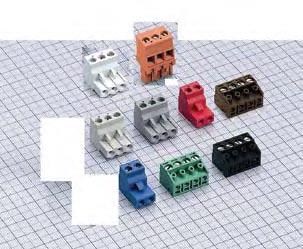


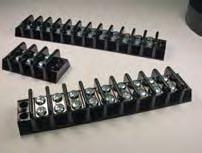
82 Filtered Power Entry RFI Filters Curtis Family of Products Custom Filters DIN Rail Terminal Blocks PCB Mount Blocks Liquid Level Controllers Custom Terminal Blocks A Div. of Powers Holdings, Inc S. 43rd St., Milwaukee, WI
Fuse & Switch. BUCHANAN Terminal Blocks. Product Facts High Density Blocks. Fuse Blocks. Switch Blocks. Common Features of 300 & 0300 Series
 Fuse & Switch Product Facts High Density n Fuse and Switch rated 15A and 300V. n High Density 0.36" [9.14] centerline spacing saves panel space; at least 33 circuits per foot. Fuse n Provide in-line circuit
Terminal Blocks. Section 12. Control Catalog 12-1
 CR151K Resilient Modular Terminal Blocks CR151C (top) and CR151A Modular Terminal Blocks DIN-rail Mounted Terminal Blocks (CR151K)...12-2 Product Tables...12-3, 12-4 Accessories...12-3, 12-4 Technical
Studded Power Feed Thru Terminal Blocks
 ST722 Series The Studded Power Feed Thru were designed for applications where power feed thru is necessary using standard double hole lugs with.625 spacing. These terminal blocks are available in three
DIN-Rail terminal blocks with ratings up to 200 ka SCCR. Multiple bridging options for point-of-use configuration. Connector products 10.
 Connector products 10 DIN-Rail terminal blocks with ratings up to 200 ka SCCR Section page Description Compact rail and panel mount blocks NDN DIN-Rail and feed through blocks 2-3 N512, NFT2, NFT3, NC3,
MAGNUM. Electrical Products. Terminal Blocks / Distribution Blocks / Quick Connect Blocks / Disconnects
 MAGNUM Electrical Products Terminal Blocks / Distribution Blocks / Quick Connect Blocks / Disconnects GET CONNECTED WITH US Bussmann Circuit Components Bussmann Circuit Components has the most complete
Section 10: Terminal Blocks
 Terminal Blocks Section : Terminal Blocks CR151K Resilient Modular Terminal Blocks DIN-rail Mounted Terminal Blocks (CR151K)...-2 Product Tables...-3, -4 Accessories...-3, -4 Technical Data...-5 Outlines
A Series 1-4 Pole Rotary Switches
 1-4 Pole Switches Features/Benefits Multi-pole and multi-position Positive detent Shorting & non-shorting contacts Panel and PCB mounting RoHS Compliant Typical Applications Automotive Major and small
 Distributed by: www.jameco.com 1-800-831-4242 The content and copyrights of the attached material are the property of its owner. Features/Benefits Multi-pole and multi-position Positive detent Shorting
Connectors. Section Contents
 Scan this tag to get the latest product information for the New Family of Terminal blocks and. Section Contents Page DIN-Rail Terminal Blocks Feed through blocks (DS series).................. 334 Feed
Kulka Military Class (A-A-59125)/(MIL-T-55164)
/(MIL-T-55164)") Kulka Military Class (A-A-59125)/(MIL-T-55164) Military Class: Closed Back These military blocks feature molded-in terminals in an improved Kulka design for greater strength and flexibility. The mounting
Kulka Military Class (A-A-59125)/(MIL-T-55164) Military Class: Closed Back These military blocks feature molded-in terminals in an improved Kulka design for greater strength and flexibility. The mounting
Switches. SERIES FEATURE ACTUATION MAX RATING SEAL RATING MOUNTING CIRCUITRY 115VAC, 28VDC)
") SWITCH SELECTION GUIDE Toggle Switches SERIES FEATURE ACTUATION MAX RATING SEAL RATING MOUNTING CIRCUITRY (Resistive @ 115VAC, 28VDC) T1 2 or 3 Position, Momentary, 8A MIL-PRF-83731 15/32" or 1/4" dia.
SWITCH SELECTION GUIDE Toggle Switches SERIES FEATURE ACTUATION MAX RATING SEAL RATING MOUNTING CIRCUITRY (Resistive @ 115VAC, 28VDC) T1 2 or 3 Position, Momentary, 8A MIL-PRF-83731 15/32" or 1/4" dia.
7000 Series Miniature Rocker & Lever Handle Switches
 Features/Benefits Multi-pole and multi-position Wide variety of actuator and termination options Epoxy terminal-seal compatible with bottom wash cleaning RoHS compliant Typical Applications Telecommunications
7000 Series Miniature Toggle Switches
 Miniature Switches eatures/benefits Multi-pole and multi-position Wide variety of actuator and termination options Epoxy terminal-seal compatible with bottom wash cleaning RoHS complaint models available
7000 Series Miniature Rocker & Lever Handle Switches
 Miniature & Lever Handle Switches Features/Benefits Multi-pole and multi-position Wide variety of actuator and termination options Epoxy terminal-seal compatible with bottom wash cleaning RoHS compliant
7000 Series Miniature Rocker & Lever Handle Switches
 Features/Benefits Multi-pole and multi-position Wide variety of actuator and termination options Epoxy terminal-seal compatible with bottom wash cleaning RoS compliant Typical Applications Telecommunications
C&K 7000 Series Miniature Rocker & Lever Handle Switches
 Features/Benefits Multi-pole and multi-position Wide variety of actuator and termination options Epoxy sealed terminals prevent contamination during soldering Typical Applications Telecommunications Instrumentation
onlinecomponents.com
 eatures/benefits Multi-pole and multi-position Wide variety of actuator and termination options Epoxy terminal-seal compatible with bottom wash cleaning RoHS complaint models available Typical Applications
Fuse Blocks and Clips
 PGE Fuse and lock s OMNI-LOK Fuse lock...................................................................................... 484-486 Midget Fuse....................................................................................................
7000 Series Miniature Toggle Switches
 Miniature Switches eatures/benefits Multi-pole and multi-position Wide variety of actuator and termination options Epoxy terminal-seal compatible with bottom wash cleaning RoHS complaint models available
C&K 1000 Series Miniature Slide Switches
 Miniature Switches Features/Benefits Variety of actuators and terminations Panel mount tabs available Epoxy terminal seal compatible with bottom-wash cleaning RoHS compliant Typical Applications Test &
Wire connection products
 Wire connection products Section Contents Page Rail mount terminal blocks NDN Series 35mm DIN rail mount blocks...282-283 N512-BK 12-Pole block... 284 NFT2-WH 2-Pole block... 284 NFT3-3-pole block... 284
C&K 7000 Series Miniature Toggle Switches
 Miniature Switches eatures/benefits Multi-pole and multi-position Wide variety of actuator and termination options Epoxy sealed terminals prevent contamination during soldering Typical Applications Telecommunications
Connectors. Section Contents
 Section Contents Page Rail mount terminal blocks NDN Series 35mm DIN rail mount blocks........ 304-305 N512-BK 12-Pole block......................... 306 NFT2-WH 2-Pole block......................... 306
A powerful way to manage your power distribution challenges. I Power Distribution Blocks
 I Power Distribution Blocks A powerful way to manage your power distribution challenges. Your problem: You re facing the enormously complex wiring requirements of an automated manufacturing facility. Or
I power distribution. Blocks. challenges. Finger-Safe / FSPDB Series...I2. MPDB Open-Style PDBs... I4. MPDB62-MPDB63 (Mini) Open-Style PDBs...
 Open-Style PDBs...") Power Distribution Blocks I A powerful way to manage your power distribution challenges. Your problem: You re facing the enormously complex wiring requirements of an automated manufacturing facility. Or
Power Distribution Blocks I A powerful way to manage your power distribution challenges. Your problem: You re facing the enormously complex wiring requirements of an automated manufacturing facility. Or
1000 Series Miniature Slide Switches
 Miniature Switches Features/Benefits Variety of actuators and terminations Panel mount tabs available Epoxy terminal seal compatible with bottom-wash cleaning RoHS compliant Typical Applications Test &
Fuseholders PAGE. Fuseholders.
 PAGE International Shock-Safe (Panel Mount).......................................................................... 467-468 Flip-Top Shock-Safe (Panel Mount)..................................................................................
BH-1 modular fuse blocks, 700 V, 400 A
 Supersedes December 1998 Agency information UL Recognized, Guide IZLT2, File E14853 up to 700 V CSA Certified, Class 6225-01, File 47235 up to 700 V CE RoHS compliant Materials Base - light-weight, high
 High barriers Recognized by UL and cul Self-extinguishing materials Nonferrous material Corrosion-resistant nickel finish Safety-grip handle A complete line of switches is available for meter, relay, instrument,
Rockers Product Selection Guide
 s Product Selection Guide Series 7000 E ET T 9000 DA D Switch Type Subminiature Subminiature & Lever andle Poles/Throws,, 3PDT, 4PDT,, 3PDT,, DPST, Max. Current 5 Amps 7.5 Amps 3 Amps 3 Amps 4 Amps Washable
R6F30A1S R6F30A1S 1P 60A 600V Fuse BLK. Features. Long Description
 3804 South Street 75964-7263, TX Nacogdoches Phone: 936-569-7941 Fax: 936-560-4685 Catalog Number Manufacturer Description Weight per unit Product Category Features Clip Type Fuse Current Rating Fuse Type
Mipco Connections for Refrigerated Containers. No One Does It Like Mipco. The Mipco. Advantage. Reliability. Safety. Easy Installation & Service
 No One Does It Like Mipco Mipco Interlocked Reefer Power Outlets are used extensively in port terminals and shipboard applications to provide a safe, watertight electrical connection for refrigerated containers.
The Best Flexible Wire Replacement with ERIFLEX FLEXIBAR STANDARD and ERIFLEX FLEXIBAR SUMMUM
 ERIFLEX FLEXIBAR The Best Flexible Wire Replacement with ERIFLEX FLEXIBAR STANDARD and ERIFLEX FLEXIBAR SUMMUM connections are made by punching directly through the laminates. No lugs to purchase, installation
E Series Sealed Miniature Rocker and Lever Handle Switches
 Sealed Miniature and Lever Handle Switches Features/Benefits Sealed against solder and cleaning process contaminants ESD Resistance all actuator options, case & bushing UL 94V-0 RoHS compliant Typical
Class H & K Fuse Holders - 250/600 Volt
 Class H & K - 250/0 Volt Specifications: Approved for 10,000 Amp Withstand Rating and Short Circuit Current Ratings (SCCR) UL Listed File No. IZLT.E35113 CSA Certified File No. LR21455 RoHS Compliant &
Type MTS Miniature Test Switches
 Type MTS Miniature Test Switches o o o o Compact and versatile Front- and back-connected styles Safe, durable, rugged and reliable Recognized by CUL & UL DESCRIPTION In many panelboard, switchgear, metering,
Compact Fluorescent Lampholders
 table of contents Compact Fluorescent Lampholders Introduction................................................... B2 Smart CFL Color-Coding Chart.................................... B3 G24q/GX24q Base.................................
CATALOG. Ty-Duct Wiring duct
 CATALOG Ty-Duct Wiring duct Thomas & Betts is now ABB Installation Products, but our long legacy of quality products and innovation remains the same. From connectors that help wire buildings on Earth to
AMPLIMITE* HDP- 20 and Economy
 AMPLIMITE* HDP- 20 and Economy Application Specification Crimp Snap Subminiature D 114-40030 Commercial s 05 MAY 11 Rev D NOTE i All numerical values are in metric units [with U.S. customary units in brackets].
305/315/355 SERIES CARD EDGE CONNECTOR.156" (3.96mm) Contact Spacing
 Contact Spacing") 305/315/355 SERIES CARD EDGE CONNECTOR.156" (3.96mm) Contact Spacing 305/315/355 SERIES ORDERING CODE Example Part Number 305-056 - 521-2 04 Series Total Number of Contacts Contact Code Insulator Style
305/315/355 SERIES CARD EDGE CONNECTOR.156" (3.96mm) Contact Spacing 305/315/355 SERIES ORDERING CODE Example Part Number 305-056 - 521-2 04 Series Total Number of Contacts Contact Code Insulator Style
IEC TERMINAL BLOCKS. Screw Clamp Connection. Feed Through DIN Rail 433. Ground DIN Rail 439. Fuse Holder DIN Rail 445. Disconnect DIN Rail 448
 CONTROL LOGIC IEC TERMINAL BLOCKS TB c3controls line of IEC terminal blocks are both innovative and user-friendly. They are simple to install and are color-coded for easy circuit identification. From standard
341/391 SERIES CARD EDGE CONNECTOR.100" (2.54mm) Contact Spacing
 Contact Spacing") 341/391 SERIES CARD EDGE CONNECTOR.100" (2.54mm) Contact Spacing 341/391 SERIES ORDERING CODE Example Part Number 341-062 - 520-2 02 Series Total Number of Contacts Contact Code Contact Rows Mounting Options
341/391 SERIES CARD EDGE CONNECTOR.100" (2.54mm) Contact Spacing 341/391 SERIES ORDERING CODE Example Part Number 341-062 - 520-2 02 Series Total Number of Contacts Contact Code Contact Rows Mounting Options
Class J modular ferrule and knifeblade fuse blocks
 Technical Data10488 SupersedesFebruary 2016 Class J modular ferrule and knifeblade fuse blocks Knifeblade fuse blocks from 100 to 600 amps feature phase barriers between poles for additional safety with
Power Distribution Blocks
 ower istribution Blocks A OWERFUL WAY TO MANAGE YOUR OWER ISTRIBUTION CHALLENGES Your problem: You re facing the enormously complex wiring requirements of an automated manufacturing facility. Or the compatibility
SERIES POWER DISTRIBUTION BLOCKS
 62000-69000 SERIES POWER DISTRIBUTION BLOCKS VERSATILE POWER DISTRIBUTION BLOCKS FOR CABLE TERMINATIONS Ferraz Shawmut Power Distribution Blocks afford a safe, convenient way of splicing cables, splitting
CONEC provides reliable and effective solutions to OEM, EMS and cable houses.
 CONEC CANADA USA CONEC designs and manufactures products in modern facilities. The products are made in accordance to the highest quality standards and industry specifications. CONEC provides reliable
8500 Series Subminiature Pushbutton Switches
 Subminiature Switches Features/Benefits Pre-travel or over-travel models available Ratings up to 3 AMPS Reliable contact design RoHS compliant Typical Applications Detection Telecommunications and networking
Card Edge Connectors Catalog Issued 7-03
 Catalog 1654080 Issued 7-03 Introduction This catalog contains product descriptions of MP Card Edge Connectors. These connectors are presented in three groups: Solder Type Board-to- Board, Press-fit Board-to-
ICT TRANSFORMERS. Industrial Control Transformers provide a low and safe control voltage for the operation of many electromagnetic devices
 ICT TRANSFORMERS Industrial Control Transformers provide a low and safe control voltage for the operation of many electromagnetic devices TA SERIES INDUSTRIAL CONTROL TRANSFORMER Industrial control transformers
Bulletin 1494V Variable Depth Flange-Mounted Disconnect Switches. Bulletin 1494F Fixed-Depth Flange-Mounted Disconnect Switches
 2 Bulletin 1494 NEMA Disconnect Switches Section Overview Bulletin 1494V Variable Depth Flange-Mounted Disconnect Switches Open Type, Fusible 30 600 A Open Type, Non-Fusible 30 600 A Page 2-3 Bulletin
 Distributed by: www.jameco.com 1-800-831-4242 The content and copyrights of the attached material are the property of its owner. Connectors Features Snap-on interface facilitates assembly Conforms to CECC
LH600303C 1/10-30A 3P 600V Class H Box Lug Fuse Block
 3804 South Street 75964-7263, TX Nacogdoches Phone: 936-569-7941 Fax: 936-560-4685 LH600303C 1/10-30A 3P 600V Class H Box Lug Fuse Block Littelfuse Catalog Number LH600303C Manufacturer Littelfuse Description
Application Specification.062 Diameter Pin and Socket Contacts and Housings 21 MAR 11 Rev E
 Application Specification.062 Diameter Pin and Socket 114-1013 Contacts and Housings 21 MAR 11 Rev E i All numerical values are in metric units [with U.S. customary units in brackets]. Dimensions are in
Table of contents. 1. Overview Product ordering and information Appendix Wiring duct styles 4. 1.
 Ty-Duct Wiring Duct 1 Table of contents 1. Overview 2 1.1 Wiring duct styles 4 1.2 How to order 5 2. Product ordering and information 7 2.1 Solid wall wiring duct 8 2.2 Wide slot wiring duct 10 2.3 Narrow
Power Distribution Blocks
 I Finger-Safe Power Distribution Blocks Power Distribution Blocks Safety evolving Ratings: Volts: 1,2,3 1500VAC/ DC; 4,5 600VAC/DC Amps: 175 to 840A SCCR: 600V or less, 100kA with proper fuse; Over 600V,
Model 10 Electromechanical Totalizer
 Model 10 Electromechanical Totalizer A 6 figure general purpose, rugged, electromechanical counter, either panel or base mounted, with manual knob reset, key reset, or non-reset. Frame and housing provides
RELOC Modular Wiring Specialty Lighting and Power Systems
 RELOC Modular Wiring Specialty Lighting and Power Systems Family FileName Description RevisionDate Access Floor Wiring DB DB Distribution Box 10/15/1999 FM FMI3 Floor Module 03/15/2002 Power Wiring System
BATTERY CONTACTS A AA AAA N SIZE PC BUTTON & SPRING CONTACTS. Ideal contacts for A AA AAA N Contacts available for.062 and.093
 BATTERY CONTACTS A AA AAA N SIZE PC BUTTON & SPRING CONTACTS Ideal contacts for A AA AAA N Contacts available for.062 and.093 size batteries. thick PC boards Space saving design installs directly onto
Product Range. Rocker & Paddle Switches. Rocker & Paddle Switches. Rocker & Paddle Switches
 Product Range for Panel Mounting: F, TRD and Gemini Series for PCB Mounting: Gemini Series Main features: Sealed or unsealed versions Various switch functions Gold or silver contacts LED illumination available
Class R 250V and 600V modular ferrule and knifeblade fuse blocks
 Technical Data 1048 Class R 2V and 600V modular ferrule and Knifeblade fuse blocks from 100 to 600 amps feature phase barriers between poles for additional safety with up to four mounting holes per pole
Fuseblocks. Voltage Ratings: Ampere Ratings: Leakage Current: Catalog/system number Torque Range System Number
 class T FuseBlocks NEW! Smaller Design Description The new Littelfuse Class T fuse blocks offer many advantages over previous generations that are noted in the features and benets section. Of particular
ches UL File No. E101598
 Instrument Transformers, Inc. Series Series 95 95 Swit Switches ches UL File No. E101598 INSTRUMENT AND CONTRC ONTROL OL s Instrument and Control Switch is a heavy-duty rotary switch that satisfies the
onlinecomponents.com
 McGILL SWITCHES Contents Introduction......................................................................... 213 McGill Rocker Switches................................................................
Heating Cable. Description
 Single Entry Power Connection Kit NEMA 4X Entry for 1 Cable 3/4 Conduit Hub Opening Lighted or Non-Lighted Multiple Entry Connection Box NEMA 4X Entry for up to 3 Cables Power, Splice or Tee Connection
ET Series Sealed Subminiature Toggle Switches
 Sealed Subminiature Switches eatures/benefits Sealed against solder and cleaning process contaminants ESD protection available Thru-hole and surface mount models Compact size and small footprint save PCB
Fuseholders Enclosed Fuseholders > Circuit Board Mounted. Shock-Safe Holder (Circuit Board Mounted) Product Characteristics.
 Product Characteristics.") Fuseholders Enclosed Fuseholders > Circuit Board Mounted Pb Shock-Safe Holder (Circuit Board Mounted) Product Characteristics Dimensions.68" 1.77".44".20".24".040".49".48".12" Compatible Fuse Types Description
Fuseholders Enclosed Fuseholders > Circuit Board Mounted Pb Shock-Safe Holder (Circuit Board Mounted) Product Characteristics Dimensions.68" 1.77".44".20".24".040".49".48".12" Compatible Fuse Types Description
 No-barrier design Self-extinguishing materials Front-connected, back-connected and flush-mounted styles Blades operate independently or can be ganged together Recognized by UL and cul STATES Type have
AMPLIMITE.050 Series Cable Assemblies, Series III
 Cable Assemblies, Series III To meet Standard Applications the following 106 ohm, black jacketed cable assemblies are available. For AMPLIMITE Series cable assemblies that meet other impedance requirements
RTA Series 1 4 Poles Coded Rotary Switches
 1 4 Poles Coded Switches Features/Benefits PCB or hand soldering versions Bushing mounting Multiple poles Decimal and hexadecimal codes Screwdriver slot or extended actuator RoHS Compliant Typical Applications
PlexPower Fused Factory Sealed Panelboard with Bus Bar Up to 30 Amps. Stainless Steel Enclosures
 Applications The PlexPower panelboard provides indoor and outdoor protection and control of electrical circuits in hazardous environments such as: Petroleum plants Chemical plants Refineries Wastewater
Distinctive Characteristics
 Distinctive Characteristics Various cap styles and colors to meet differing application needs. Bright, full face illumination to distinctively indicate status. Rear panel threaded mounting or snap-in mounter
T CLASS T FUSE BLOCKS
 Ferraz Shawmut Fuse Blocks accommodate fuses up to 600A. Insulators are either of durable, glassfilled polycarbonate (GFPC) or phenolic with verified dielectric strength in excess of 2500V. Ferraz Shawmut
Liquid Level Switches and Sensors
 Liquid Level Switches and Sensors Madison Company's comprehensive line of level sensors includes single- and multi-point level switches, continuous level and conductivity sensors and more. The wide selection
Power Distribution Blocks
 Power Distribution Blocks One powerful way to manage your power distribution problems. Your problem: You re facing the enormously complex wiring requirements of an automated manufacturing facility. Or
Rotary Switches Product Selection Guide
 Switches Product Selection Guide Series A RTA M R F H RW RM ENC Switch Type Multi-pole/ Multi-position Multi-pole/ Multi-position Half-inch Rota-slide Rota-slide Power Rota-slide Subminiature SMT Subminiature
table of contents Switches J 1 SECTION SECTION J Quick Guide to Switches... J2-J3
 table of contents Switches Quick Guide to Switches....................................... J2-J3 Push Switches.............................................. J4-J7 Single Pole ON-OFF.......................................
Heating Cable. Description
 203312 Single Entry Connection Box NEMA 4X Entry for 1 Cable 3/4 Conduit Hub Opening Multiple Entry Connection Box NEMA 4X Entry for up to 3 Cables Power or Tee Connection 3/4 Conduit Hub Opening End Seal
ST SERIES - MINIATURE TOGGLE SWITCHES
 ST SERIES - MINIATURE TOGGLE SWITCHES K FEATURES Dry circuit through power ratings. Ultra-rugged construction SPDT & DPDT models with numerous options. Panel, panel & p.c. and p.c. mounting models, lighted
M Series Half-inch Rotary Switches
 Half-inch Switches Features/Benefits Multi-pole and multi-positions Panel and PCB mounting Stainless steel actuator Non-shorting contacts RoHS Compliant IP67 (F option only) Typical Applications Test equipment
E Series Sealed Miniature Toggle Switches
 Sealed Miniature Switches eatures/benefits Sealed against solder and cleaning process contaminants UL 94V-0 Nylon case and bushing Multi-positions ESD protection available RoHS compliant models available
Flame-retardant PVC offers the protection you need.
 Solid wall wiring duct Flame-retardant PVC offers the protection you need. Solid wall duct PVC Engineered to restrict wire access Constructed of flame-retardant PVC Improved flush sidewall and cover style
Cam-Lok Single Pole Connectivity. The industry standard for reliable service under the most severe operating conditions.
 Cam-Lok Single Pole Connectivity The industry standard for reliable service under the most severe operating conditions. Cam-Lok Single Pole Connectivity Cam-Lok connectors are the industry standard Cam-Lok
PIN & SLEEVE DEVICES
 PIN & SLEEVE DEVICES line of industrial plugs and sockets are manufactured by ABL Sursum, a company well known in Europe for its quality electrical products. This major manufacturer combines the elements
Switches & Motor Controls
 Toggle Switches... A-2 Traditional Switches... A-2 CO/ALR Switches... A-14 Lev-Lok Modular Switches... A-15 Decora Switches... A-16 Appliance Switches... A-23 Anywhere RF Remote Switches... A-25 Manual
Wiring Duct T1 Series - Slotted
 Duct T1 Series - Slotted UL file E123572 T1 Series Gray Open Slot Rigid PVC (including cover) Catalog Standard Carton Package Quantity Price Catalog Single Piece Pkg Package Quantity Price T1-0506G 20
THREADED & BAYONET CONNECTORS FOR DEMANDING ENVIRONMENTS
 MILITARY AND COMMERCIAL AVIATION MIL - DTL - 83723 SERIES III THREADED & BAYONET CONNECTORS FOR DEMANDING ENVIRONMENTS CONNECTORS FOR DEMANDING ENVIRONMENTS THREADED AND BAYONET MILITARY AND COMMERCIAL
Cam-Lok. Single pole connectivity. The industry standard for reliable service under the most severe operating conditions.
 Plugs & receptacles Cam-Lok single pole connectivity Cam-Lok Single pole connectivity The industry standard for reliable service under the most severe operating conditions. Cam-Lok single pole connectivity
Picoflex. 1.27mm IDT Connector System for Ribbon Cable Applications
 Picoflex 1.27mm IDT Connector System for Ribbon Cable Applications Picoflex Markets & Applications The versatile Picoflex IDT connector system is ideal for a broad range of applications across all market
Up to 60 A Class R 250 V and 600 V ferrule power distribution fuse blocks
 Technical Data 09 Effective June 06 Up to 60 A Class R 50 V and 600 V ferrule power distribution fuse blocks Catalog symbols: RM5060-_MW_ RM60030-_MW_ RM60060-_MW_ Features and benefits: Combination power
37T Series Moisture Resistant Temperature Controls
 37T Series Moisture Resistant Temperature Controls Moisture Resistant Temperature Control The 37T series of 3/4 (19mm) bimetal disc temperature controls from Therm-O-Disc offers proven reliability in a
Standard Timer Connectors
 Standard Timer Connectors Application Specification 114-49003 22 FEB 12 NOTE i All numerical values are in metric units [with U.S. customary units in brackets]. Dimensions are in millimeters [and inches].
RTBH Series 1-2 Pole Coded Rotary Switches
 RTBH Series 1-2 Pole Coded Switches Features/Benefits Totally sealed Detent angles, 15, 22.5, 30 and 36 Multi pole Coding functions Robust construction RoHS Compliant Typical Applications Telecommunications
Parts Manual. Transfer Switch. OTPCB (Spec A) 150/225/260 Amps. English Original Instructions (Issue 4)
 150/225/260 Amps. English Original Instructions (Issue 4)") Parts Manual Transfer Switch 50/225/260 Amps OTPCB (Spec A) English Original Instructions -203 962 0228 (Issue ) This catalog covers models produced under the Cummins /Onan and Cummins Power Generation
Parts Manual Transfer Switch 50/225/260 Amps OTPCB (Spec A) English Original Instructions -203 962 0228 (Issue ) This catalog covers models produced under the Cummins /Onan and Cummins Power Generation
Power distribution components
 Industrial electronics Power distribution components Reliable, cost-effective, complete R England sv_001.fm Rittal power distribution components Bar centre distance (mm) Number of poles Busbar dimensions
Quick Reference Guide AMP CT Connector Series
 Quick Reference Guide The AMP CT connectors are a miniature wire-to-board and wire-to-wire interconnect solution. The AMP CT connector series has proven performance in its harness making capability. A
FASTON* 110 Series. Receptacle With F Crimp Insulation Support Barrel. Wire Barrel. Insulation Support Barrel. Figure 1
 FASTON* 110 Series Application Specification Flag Receptacles with F Crimp Feature 03 SEP 13 NOTE NOTE i All numerical values are in metric units [with U.S. customary units in brackets]. Dimensions are
Distinctive Characteristics
 Distinctive Characteristics Full face or spot illumination with incandescent lamps or multi-element LEDs, with or without resistors. Short Body Pushbuttons Series YB Choice of super bright LEDs in white,
Fine Pitch SMT Stacking Connectors (Parallel Board-to-Board) Fine Pitch SMT Stacking Connectors (Parallel Board-to-Board) Stacking Height mm inch
 Fine Pitch SMT Stacking Connectors (Parallel Board-to-Board) Stacking Height mm inch") Fine Pitch SMT Stacking Stacking Height Guide for Parallel Board-to-Board Applications Fine Pitch SMT Stacking Stacking Height Guide for Parallel Board-to-Board Applications (Continued) Stacking Height
Fine Pitch SMT Stacking Stacking Height Guide for Parallel Board-to-Board Applications Fine Pitch SMT Stacking Stacking Height Guide for Parallel Board-to-Board Applications (Continued) Stacking Height
9000 Series Power Rocker and Lever Handle Switches
 Power and Lever Handle Switches Features/Benefits Thermoset UL 94V-0 housing Rugged construction Variety of actuator and termination options RoHS compliant Typical Applications Small equipment Shut-off
Heating Cable. Description
 203312 Single Entry Connection Box NEMA 4X Entry for 1 Cable 3/4 Conduit Hub Opening Multiple Entry Connection Box NEMA 4X Entry for up to 3 Cables Power or Tee Connection 3/4 Conduit Hub Opening End Seal