X-Plane 11 Boeing
|
|
|
- Curtis Chandler
- 5 years ago
- Views:
Transcription
 Copyright: Laminar Research 2018 X-Plane 11 Boeing 737-800 Disclaimer The information contained in this document is for simulation use only, within the X-Plane flight simulator.")
1 Pilot s Operating Manual Author: Julian Lockwood (julian@x-plane.com) Copyright: Laminar Research 2018 X-Plane 11 Boeing Disclaimer The information contained in this document is for simulation use only, within the X-Plane flight simulator. This document is not subject to revision and has not been checked for accuracy. This document is intended for entertainment only and may not to be used in situations involving real-life aircraft, or real-life aviation. Distribution This document may be copied and distributed by Laminar Research customers and developers, for entertainment. It may also be distributed with third-party content developed for X-Plane 11. 1
2 Contents Background: The Boeing B Series Specifications... 6 The X-Plane B Views and Controls... 8 Creating Quick Look views... 9 Operating the controls Assigning peripheral devices A Tour of the Cockpit Forward Overhead Panel Flight Controls AC and DC Metering Transfer Standby Power & Generator Bus Fuel Ice & Rain Protection Temperature Control Pneumatics Hydraulics Miscellaneous Aft Overhead Panel Emergency Locator Transmitter (ELT) Dome Light Audio Control Electronic Engine Control (EEC) Primary Instrument Panels Electronic Attitude Director Indicator (EADI) Electronic Horizontal Situation Indicator (EHSI) Backup EADI/EHSI Instrument Lighting Control Panel Chronometer Tiller Annunciators
3 Electronic Attitude Director Indicator (EADI) Components Mach Number FMC SPD LNAV VNAV Altitude Pre-Set Altitude Scale Flight Director Horizontal Deviation Bar Current Altitude ILS Vertical Deviation Scale Static Reference Lines Airspeed Scale Current Airspeed Flight Director Vertical Deviation Bar Altitude Above Ground (AGL) Heading Bug Magnetic Heading Altimeter Setting Electronic Horizontal Situation Indicator (EHSI) Components Electronic Horizontal Situation Indicator (EHSI) Control Panel Flight Path Vector Display MTRS Baro Rotary VOR Map Display Distance Features Buttons MINS Reference Selector VOR EHSI Mode Center Panel Upper EICAS (Engine Indications and Crew Alerting System) Display Lower EICAS (Engine Indications and Crew Alerting System) Display FMS Control Display Units (CDUs)
4 Center Pedestal Thrust Levers Speed Brake Lever Flap Lever Pitch Trim Wheel Fuel Control Levers VHF (Comm) Radios NAV Radios Transponder Audio Control Lighting Trim Autopilot Operation Auto-Land Flight Planning Fuel Calculation Load Sheet Tables Setting the Weight, Balance and Fuel in X-Plane Checklists Pre-Flight Exterior Inspection Cold and Dark to Engine Start Before Taxi Before Takeoff After Takeoff Cruise Before Landing Landing After Landing Parking
 began in 1966, with capacity for 85 passengers, five-abreast seating, and powered by two Pratt & Whitney JT8D-15 low-bypass turbofan engines,")
5 Background: The Boeing 737 The Boeing corporation developed the 737 in the mid-1960s to serve as a lower-cost twin-engined, shortrange companion to the larger 727 and 707 models. Production of the original variant (designated 100) began in 1966, with capacity for 85 passengers, five-abreast seating, and powered by two Pratt & Whitney JT8D-15 low-bypass turbofan engines, situated beneath the wings. A slightly larger model 200 followed in 1967, with increased thrust to compensate for additional weight. In 1984, Boeing introduced the first of three variants that would subsequently be designated Classics. These were the 300, 400 and 500 series. The new models were heavily revised, and featured winglets for increased lift and range, and CFM International CFM56-3C-1 high-bypass turbofan engines. Modifications to the landing gear to incorporate the larger engines was required. The Classics were larger, quieter and more economical, and also featured EFIS CRT avionics, replacing conventional instrumentation. In 1998, Boeing again heavily revised the 737, with the 600, 700, 800 and 900 variants, designated NG (Next Generation). These aircraft featured FADEC controlled CFM56-7 high-bypass turbofan engines, larger and more efficient wings (without winglets in some cases), a strengthened fuselage, revised avionics, and a higher cruise speed. In 2016 (as a response to the Airbus A320 NEO), Boeing introduced the MAX series designated MAX-7, MAX-8, MAX-9, MAX- 10, MAX-200. The MAX-8 was the first to enter service in The MAX variants offer four lengths, with options for 138 to 230 seats and a range of between 3,215 and 3,825 nautical miles. These aircraft are equipped with split winglets and powered by the CFM International LEAP high-bypass turbofan engines. The Boeing 737 (all variants including military and cargo not discussed above) is the highest-selling commercial jetliner in history, with over 10,000 deliveries as of
6 B Series Specifications Engines: Model x CFM56-7B24 turbofans Power x 24,200 lb. thrust Fuel: Capacity ,875 Gallons / 26,020 liters / 46,000 lbs. Fuel Jet A-1 Fuel Burn (average) ,700 lbs. per hour Weights and Capacities: Max. Takeoff Weight ,000 lbs. / 79,000 kg. Max. Landing Weight ,500 lbs. / 66,000 kg. Empty Operating Weight ,700 lbs. / 41,500 kg. Maximum Payload ,300 lbs. / 20,540 kg. Maximum Passengers Performance: Max. Level Speed KTAS Long Range Cruise Speed KTAS Final Approach Speed KTAS (full flap/gear down) Takeoff Distance ,700 ft. / 2,650 m. Landing Distance ,360 ft. / 1,635 m Range ,000 nm Service Ceiling ,000 ft. / 12,500 m. 6
 and breaks down the forces on each part separately.")
7 The X-Plane B Unlike other flight simulators, X- Plane employs a technique called blade element theory. This utilizes the actual shape of the aircraft (as modeled in the simulator) and breaks down the forces on each part separately. The force of the air acting on each component of the model is individually calculated, and combined, to produce extremely realistic flight. When you fly an airplane in X- Plane, there are no artificial rules in place to govern how the aircraft behaves. Your control inputs move the control surfaces of the aircraft, and these interact with the virtual flow of air around it. As such, you may consider that you are really flying the aircraft. Due to the use of Blade Element Theory in X-Plane, an aircraft must be modeled with great accuracy, in order that it behave like its real-life counterpart. This means the fuselage, wings and tail surfaces must be the right size and shape, the center of lift and center of gravity must be in the right places, and the engine(s) must develop the right amount of power. In fact, there are a great many properties that must be modeled correctly to achieve a high-fidelity flight model. The featured in X-Plane-11 has been modeled by our design team with a degree of accuracy that ensures its flight characteristics are like the real aircraft. However, despite this, some differences will be apparent, because even the smallest factor plays into the ultimate behavior of the aircraft, both in real life, and in X-Plane. The systems modeling of this aircraft involves some compromise too, because of the degree of complexity present in the real aircraft. However, in most cases, the actual procedures could be followed when operating the X-Plane version. Checklists are presented later in this document (with modifications to suit this specific simulation platform and model). It is recommended that X-Plane pilots follow those procedures to extract the maximum capability and enjoyment from this aircraft. 7
, electrical systems, pneumatic systems, navigation aids, radios, autopilot, interior and exterior lighting, and fuel systems.")

8 Views and Controls The X-Plane B features a detailed 3-D cockpit with a great many of the primary controls and systems modeled, including: Flight controls (yoke, rudder pedals, thrust levers, prop levers, condition levers), electrical systems, pneumatic systems, navigation aids, radios, autopilot, interior and exterior lighting, and fuel systems. Hint: To best view some of the switches featured in this aircraft, it is helpful to hide the pilot and co-pilot yokes. This can be accomplished selecting Joystick and Equipment from the Settings menu, and assigning a button, or key, to the following: Operation Toggle Yoke Visibility (The default keyboard assignment is y ). Use the assigned button/key to toggle the yoke view as required. This will have no effect on the yoke operation. 8


 with their physical locations in the cockpit, and are")
9 Creating Quick Look views Before discussing the controls, we suggest that the pilot establish a series of Quick Look views that will be helpful later when interacting with this particular aircraft. If you are not familiar with this technique, more information is available in the X-Plane Desktop Manual. The following Quick Look views are recommended for the B , in a situation where the pilot is not using a Virtual Reality (VR) headset, or a head tracking device. To some degree, these correspond (on the keyboard Number Pad) with their physical locations in the cockpit, and are therefore logical and easy to recall later. Control Display Unit (CDU) Pilot s Primary Instrument Panel Thrust Lever Quadrant and Center Console 9


10 Co-Pilot s Primary Instrument Panel Pilot s EFIS (Electronic Flight Instrument System) Control Panel Engine Instrument Panel / Autopilot Panel Co-Pilot s EFIS (Electronic Flight Instrument System) Control Panel 10


11 Pilot s Left Glance View Overhead Panel Co-Pilot s Right Glance View 11


12 Operating the controls This section covers the basics techniques for the operation of the controls that you will encounter in the cockpit of an X-Plane aircraft. Control manipulators are consistent across all X-Plane 11 aircraft. However, the specific ILLUSTRATIONS in THIS chapter may differ from YOUR aircraft. Toggle and Rocker switches are operated with a single click of the mouse. Place the mouse pointer slightly above, or below, the center point of the switch, depending on the direction you intend to move it. A small white arrow is displayed to confirm the intended direction. Click the mouse button to complete the operation. Levers are operated by assigning a peripheral device to the necessary axes in X-Plane (throttle, prop, mixture etc.). More information is available in the X-Plane Desktop Manual. Levers may also be operated by clicking and dragging the mouse pointer. Some rotary dials are operated by positioning the mouse pointer on top of the control, and then a click and drag to the right, or to the left. The same can be accomplished using the mouse wheel - if one is present on your device. Other rotary controls require finer precision. When the mouse pointer is positioned slightly to the left of such a control, a counter-clockwise arrow appears. This indicates that you are ready to rotate the control counter-clockwise. Correspondingly, a clockwise arrow indicates that you are ready to rotate the control clockwise. After positioning the mouse pointer, changing the frequency in the desired direction is accomplished in two ways: i) By rolling the mouse wheel forwards, or backwards ii) By clicking (dragging is not supported here) Radio and Navigation frequency rotary dials are grouped together as twin concentric knobs. Here, the larger rotary is used to tune the integer portion of the frequency, and the smaller rotary is used to tune the decimal portion. Each works independently, using the same technique, as described above. 12


.")

13 Push buttons are operated by pointing and clicking with the mouse. Guarded switches are used in situations where accidental activation of the switch must be prevented. To operate a guarded switch, the guard must first be opened. Do this by positioning the mouse pointer over the switch until the two vertical white arrows are displayed. Click once. If the switch is currently closed, it will open, and viceversa. After the guard has been opened, the switch may be operated like a toggle and rocker switch (see earlier in this section). The Yoke / Stick / Joystick is operated by assigning a peripheral device to the roll and pitch axes in X-Plane. This is discussed in greater detail later in the guide. The Rudder Pedals are operated by assigning a peripheral device to the yaw axis in X-Plane. If your rudders also support toe braking, create additional assignments to the left toe brake and right toe brake axes in X-Plane. This is discussed in greater detail later in the guide. Note that you may also assign keys on your keyboard, or buttons on your external peripheral to move the rudder to the left or right, or to center the rudder. 13

 to the Roll command in X-Plane, and the vertical axis to the Pitch command.")

14 Assigning peripheral devices This section of the manual deals with an ideal scenario, in terms of the assignment of external computer peripherals to operate the X-Plane B with the highest degree of realism. If you are missing some of these external peripherals, you may elect to choose a different configuration that better suits your hardware. The B is equipped with Yokes, for roll and pitch control. To simulate this, assign the lateral axis of your yoke (or joystick) to the Roll command in X-Plane, and the vertical axis to the Pitch command. More information is available in the X-Plane Desktop Manual. The B is equipped with dual thrust levers which control the thrust generated by the left and right engines respectively. To simulate the thrust levers for a B , assign two levers on your quadrant to the Throttle 1 and Throttle 2 property in X-Plane. The B is equipped with a Fuel Flow lever for each engine. These are manually actuated by the flight crew to introduce fuel to the engines during the start procedure. To simulate this, assign two levers on your quadrant to the Mixture 1 and Mixture 2 properties in X-Plane.. 14


15 The B is equipped with a Flap lever, which controls the deployment of the flaps for takeoff and landing. To simulate this, assign a peripheral lever to the Flaps property in X-Plane.. The B is equipped with a Landing Gear lever. To simulate this, assign a peripheral lever to the Landing gear property in X-Plane.. The B has conventional rudder controls, actuated by the rudder pedals. The pedals activate the rudder, which is part of the tail assembly, and this yaws the aircraft to the left or right. The rudders keep the aircraft straight during takeoff and landing, and help make coordinated turns. To simulate this, assign the yaw axis of your pedals peripheral device (or a joystick axis) to the yaw property in X-Plane. 15

 to the left toe")
16 The B has rudder toe-braking, actuated by the tip of the rudder pedals. To simulate this, assign the brake toe-tipping motion of each individual pedal (or a joystick axis) to the left toe brake and right toe brake property in X-Plane. 16

17 A Tour of the Cockpit In this section of the manual, the cockpit will be broken down into distinct functional areas, and the controls that are featured in those areas will be identified and described. This will assist in locating the necessary instruments and controls later, when working through the aircraft check lists, and flying the aircraft. Forward Overhead Panel The forward overhead panel comprises a collection of smaller panels that manage the aircraft s electrical, pneumatic, lighting, pressurization, engine start, and other systems. Many of these were previously the domain of a flight engineer in the era of threeperson flight crews. Note: Not all of the functions contained within these panels are fully simulated in the X-Plane model. 17

18 1. Flight Controls This panel is used to select the active flight control systems (rudder, flaps, spoilers, and features a yaw damper toggle switch. In the X-Plane model of the , this panel supports only the Yaw Damper toggle switch. 2. AC and DC Metering This panel is used to select and monitor the source of electrical power to the aircraft (both DC on the left, and AC on the right. It also features the master battery switch. 18
 system to both")

19 3. Transfer This panel is used to control the active navigation devices, in the event of a failure. If either Nav Radio receiver / Inertial Reference System / Flight Management Computer fails, the associated control switches on this panel may be used to transfer the remaining (good) system to both pilot and first-officer in unison. In Normal mode, these systems may be used independently by the pilot and first-officer. The SOURCE Rotary is used on the ground for maintenance purposes. The CONTROL PANEL Rotary manually switches control of left and right-side displays to a single EFIS control panel. In the X-Plane model of the , this panel supports only the VHF NAV switch. 4. Standby Power & Generator Bus This panel controls the standby electrical buses (AUTO, BAT or OFF). AUTO is the normal mode and will engage the battery standby electrical buses (via a relay), automatically when needed. BAT - forces manual transfer to the standby electrical buses. OFF - standby electrical buses are not powered. The Disconnect switches remove the left or right generators from providing power to the electrical buses in the event of a failure of the corresponding generator. The GRD PWR switch engages the use of ground electrical power (via an umbilical cable) if this is available. The BUS TRANSFER switch controls the automated transfer of power to the remaining good generator, in the event of a failure of the other generator. The GEN 1 and GEN 2 switches activate the main electrical generators which are fed from the engines (when running). The APU GEN 1 and APU GEN 2 switches activate the Auxiliary Power Unit electrical generators. These are powered by the APU turbine at the rear of the aircraft, which is a preliminary source of power prior to engine start. 19


20 5. Fuel This panel controls the fuel flow and fuel pumps. The Fuel Temp gauge reports the temperature of the fuel in tank #1. Fuel is heated using the engine oil, to minimize icing potential. The lower portion of this panel is arranged schematically, and the fuel pump switches represent the actual location of the pumps in the aircraft. These switches control the fuel pumps for tanks 1 (left), 2 (right), and the center tank. The cross-feed rotary opens or closes the cross-feed valve. When open, either of the engines may source fuel from any tank. Under normal circumstances, the left engine is fed by the left, and center tanks, and the right engine by the right and center tanks. 6. APU and Engine start / External Lights This panel supports two main functions: APU and Engine start, and control of the external taxi, runway, and collision lights. Starting the APU is accomplished by holding the switch in the START position for a few seconds, then releasing back to the ON position. APU shut-down is accomplished by moving this switch to the OFF position. The engine ignition system in use is controlled by the switch located between the two engine start rotaries. There are two independent ignition systems, which may be used in isolation (LEFT or RIGHT), or together (BOTH) Engine start is accomplished by turning the left or right engine rotary control to GND until the start sequence has been completed (covered in detail in the checklists later in this guide). Once the engine has been started, this switch is normally set to AUTO, However, in the event of sever precipitation, turbulence or icing, these switches should be set to CONT (continuous use of selected igniter) or FLT (continuous use of both igniters). This prevents a possible engine flame-out. The external landing lights are controlled by the switches at the left side of this panel. The two left-most switches control the (wing) outboard lights, and the two right-most the (wing) inboard lights. The anti-collision lights are controlled by the switches at the right side of this panel. 20
.")

21 7. Ice & Rain Protection This panel is used to control the window and pitot tube heaters, to protect against fogging and icing. Switches at the top of this panel are provided to activate the left-side and forward window heaters, the right-side and forward window heaters, and the two-external pitot-tube heaters (A and B). Switches at the bottom of this panel are provided for the wing (electrical) anti-ice, and engine intake anti-ice heaters. 8. Temperature Control This panel monitors and controls the cabin temperature. The rotary control at the top-right is used to select the region of the cabin to be monitored, with the associated temperature being displayed by the gauge to at the upper-left. The three rotary controls at the lower portion of the panel set the temperature of (left to right) the flight deck, forward cabin, and aft cabin. 21


22 9. Pneumatics This panel controls the aircraft pneumatic system, which can be supplied by the engines, APU or a ground source. The pneumatic system provides air for engine starting, air conditioning packs and the wing antiice boots. The DUCT PRESSURE gauge displays the available air pressure in the left, and right pneumatic systems. The recirculating fans recirculate filtered air back to the cabin, to reduce bleed air requirements. The LEFT PACK and RIGHT PACK switches direct bleed air to the air-conditioning packs, for cabin environmental control. The isolation valve is used to isolate the left and right pneumatic systems. When set to AUTO, this valve opens and closes automatically, as required by the pneumatic systems. When set to CLOSE, the left and right pneumatic system operate independently. The Wing Anti-ice switches direct bleed air to the left and right de-icing boots at the leading edge of the wings. When the APU Bleed switch is on, the pneumatic system is pressurized using bleed air from the Auxiliary Power Unit (APU). This is a small (internal) turbine located at the rear of the aircraft. 10. Hydraulics Pressure to the two hydraulic systems (A and B) may be provided from engine-driven, and electrical-driven pumps. The switches on this panel control the source of hydraulic pressure. Hydraulic system A may be sourced from engine-driven pump #1, or electrical-driven pump #2, or both. Hydraulic system B may be sourced from engine-driven pump #2, or electrical-driven pump #1, or both. 22

. 12.")

23 11. Cabin Pressurization This panel displays and controls the cabin pressurization. The gauges on the left show the current cabin pressure, and the differential between the internal, and external pressures. The FLT ALT rotary is used to manually set the anticipated peak altitude for the flight (in feet). The LAND ALT rotary is used to manually set the landing altitude for the termination of the flight (in feet). 12. Miscellaneous Rotary controls for the circuit breaker board lighting level, and overhead panel backlighting are located at the top of this panel. The circuit breaker boards themselves are located on the back wall of the cockpit, behind the pilot and first-officer. The EMERGENCY EXIT LIGHTS guarded switch controls the state of these lights. When ARMED, the lights will illuminate automatically. When ON, the lights are illuminated immediately. The Flight attendant and ground personnel call buttons are located on this panel. Also, the FASTEN SAFETY BELTS switch. A rotary control exists at the bottom of the panel to control the windshield wipers. 23

24 Aft Overhead Panel The aft overhead panel comprises a collection of smaller panels that manage the aircraft s electrical, pneumatic, lighting, pressurization, engine start, and other systems. Many of these were previously the domain of a flight engineer in the era of threeperson flight crews. Note: Not all of the functions contained within these panels are fully simulated in the X-Plane model. 24
25 1. Emergency Locator Transmitter (ELT) This panel is used to control the activation status of the Emergency Locator Transmitter (ELT). When in the (guarded) ARM position, the ELT will activate automatically in the event an impact is detected. When in the ON position, the ELT activates immediately. The annunciator is illuminated when the ELT is operating. 2. Dome Light This panel contains a single switch used to control the overhead cockpit dome lighting. 25
 radio.")
 radio. 4.")
26 3. Audio Control This panels controls the active mic, and active audio source. The buttons along the top of the panel activate or deactivate the associated mics. For example, clicking the VHF1 button to ON will activate the mic connected to the VHF 1 (pilot-side) radio. The illuminated rotaries below the buttons behave as toggle switches, and are used to activate, or deactivate the associated audio source. For example, clicking the toggle below the VHF1 button will activate audio from the VHF 1 (pilot-side) radio. 4. Electronic Engine Control (EEC) This panel controls the Electronic Engine Control system mode. The Engine Control annunciators illuminate when a malfunction is detected in the electronic engine control system, or the flight conditions data required by this system is compromised. The EEC buttons provide control over the Electronic Engine Control system. When ON is selected, this engages NORMAL mode the EEC uses the current flight conditions (temperature, pressure and other data) to protect from exceeding the redline value for N1 (the lowpressure compressor fan). In ALTN (alternate) mode, the EEC uses the last valid flight conditions (before becoming compromised) to accomplish this task. Reverser annunciators illuminate temporarily when the thrust-reverser retracts back to the stowed position. The annunciates illuminate permanently when a malfunction in the thrustreversers is detected. 26
 position, the flight recorder operates anytime the engines are running.")

 and ON (supplemental oxygen system")
27 5. Flight Recorder This panel controls the flight data recorder. When in the NORMAL (guarded) position, the flight recorder operates anytime the engines are running. When in the TEST position, the flight recorder operates regardless of engine status. 6. Oxygen The CREW OXYGEN gauge indicates the pressure available in the crew oxygen cylinder, which provides supplemental oxygen in the event of a pressurization failure. The annunciator illuminates if the passenger supplemental oxygen system has deployed. The PASSENGER OXYGEN guarded switch has two modes NORMAL (supplemental oxygen system deploys automatically) and ON (supplemental oxygen system deploys immediately). 7. Redundant Landing Gear Annunciators A separate set of annunciators that indicate the status of the landing gear - to provide redundancy in the event the primary annunciators (on the main instrument panel) fail. 27
 - via the scale on the right.")
28 Primary Instrument Panels Electronic Attitude Director Indicator (EADI) This is the left LCD panel in the avionics cluster. The EADI displays the attitude of the aircraft relative to the horizon, and the altitude (above sea level) - via the scale on the right. The attitude display informs the pilot whether the aircraft is flying straight, or turning, and whether the aircraft is climbing, or descending. This information is crucial in instrument conditions - when the outside horizon is not visible. The EADI also displays localizer and glideslope deviation, when coupled to an ILS approach. The EADI is covered in detail in a separate chapter: Electronic Attitude Director Indicator (EADI) Components 28
29 Electronic Horizontal Situation Indicator (EHSI) This is the right LCD panel in the avionics cluster. The EHSI displays the aircraft s position & (magnetic) heading. The display is presented in a plan view, as if looking down at the aircraft from directly above. If a flight plan has been input (using the FMS), this panel also displays the aircraft s position relative to the desired track. The EHSI is covered in detail in a separate chapter: Electronic Horizontal Situation Indicator (EHSI) Components Backup EADI/EHSI This instrument provides redundancy in the event of a failure of the primary EADI and EHSI and combines the functions of both into a single unit. The backup EADI/EHSI is powered by a separate electrical source. 29
. LOWER DU controls the brightness of the lower-center multi-function display unit (See: xxx).")
30 Instrument Lighting Control Panel This panel contains a series of rotary controls that adjust the instrument lighting. MAIN PANEL controls the backlighting to the upper and lower instrument panels. UPPER DU controls the brightness of the upper-center multi-function display unit (See: xxx). LOWER DU controls the brightness of the lower-center multi-function display unit (See: xxx). BACKGROUND controls the brightness of the lower instrument panel flood lighting. ADFS FLOOD controls the brightness of the upper instrument panel flood lighting. OUTBO DU controls the brightness of the EADI. INBO DU controls the brightness of the EHSI. Chronometer This instrument displays the current time, and (flight) elapsed time. Current time is displayed in UTC, or local (controlled by the button at the upper-right). Start, Hold and Reset the chronometer timer using the CHR button at the upper-left. 30


31 Tiller Large aircraft are frequently equipped with a tiller for nosewheel steering. The tiller here will respond to rudder commands for steering on the ground. Annunciators A/P P/RST: Auto-pilot caution or warning. Push to reset. A/T P/RST: Auto-throttle caution or warning. Push to reset. FMC P/RST: Flight Management Computer caution or warning. Push to reset. TAKEOFF CONFIG: Takeoff configuration caution or warning. CABIN ALTITUDE: Cabin pressurization system is not operating, and cabin altitude is above safe limits. SPEED BRAKE ARMED: Automatic speed-brake deployment is armed for landing. This panel displays the status of the aircraft s equipment and systems. Red indicators are warnings, amber indicators are cautions, and green indicators are for information. Every annunciator light on this panel may be illuminated by moving the LIGHTS switch to TEST. This ensures they are operational before a flight. SPEED BRAKE DO NOT ARM: Automatic speed-brake deployment armed, but a failure has been detected. STAB OUT OF TRIM: Illuminates when the auto-pilot is engaged and a high degree of trim has been applied. The pilot needs to be aware of this when resuming manual control of the aircraft. 31
32 Electronic Attitude Director Indicator (EADI) Components 1 Mach Number Airspeed expressed as a percentage of the speed of sound (Mach-1). 2 FMC SPD Aircraft speed is controlled by the FMC (Flight Management Computer) 3 LNAV LNAV (Lateral Navigation Mode) engaged. The autopilot will steer the aircraft laterally according to the programmed flight plan. 4 VNAV VNAV (Vertical Navigation Mode) engaged. The autopilot will manage altitude according to the programmed flight plan. 5 Altitude Pre-Set Pre-set altitude at which the autopilot will level off. 32
33 6 Altitude Scale 7 Flight Director Horizontal Deviation Bar When the aircraft is following a flight-plan, or according to a navigation aid, this bar informs the pilot to climb, or descend, to intercept the desired altitude. 8 Current Altitude 9 ILS Vertical Deviation Scale Displays the extent of any vertical deviation above, or below the desired ILS glide slope. 10 Static Reference Lines A static reference showing the position of the aircraft with respect to the artificial horizon in terms of ascent, descent, a left turn, or a right turn. 11 Airspeed Scale 12 Current Airspeed Flight Director Vertical Deviation Bar Altitude Above Ground (AGL) When the aircraft is following a flight-plan, or according to a navigation aid, this bar informs the pilot to steer left, or right, to intercept the desired track. Altitude Above Ground (from the radio-altimeter) between 0 and 2,500 feet 15 Heading Bug Sets the desired heading for the autopilot (when in the appropriate mode). 16 Magnetic Heading The aircraft s current magnetic heading. 17 Altimeter Setting STD (29.92 inches of mercury) or manual setting. 33
.")
34 Electronic Horizontal Situation Indicator (EHSI) Components 1 GS / TAS / Wind GS: Ground Speed TAS: True Air Speed Wind speed and direction. The graphic indicates wind direction relative to the aircraft s current heading. 2 Current Magnetic Heading 3 Heading Bug Sets the desired heading for the autopilot (when in the appropriate mode). 4 Next Flight Plan Waypoint If a flight plan is currently in effect 5 VOR Information Frequency and distance of VOR tuned by NAV radio 6 Flight Plan Course 34
35 7 VOR The location of a VOR relative to the current position of the aircraft 8 Next Flight Plan Waypoint 9 Airport The location of an airport relative to the current position of the aircraft The features currently displayed by the EHSI 10 Active Features ARPT: Airports are displayed WPT: Waypoints are displayed STA: Radio navigation aid STATIONS WXR: Weather radar 11 Waypoint 12 Current Location 35

36 Electronic Horizontal Situation Indicator (EHSI) Control Panel A separate EHSI Control Panel is provided for the pilot and first-officer. These work independently, and are used to control and customize the settings and information presented on the left, and right EHSI display: 1 Flight Path Vector Display Not currently supported 2 MTRS Selects the additional display of EADI altitude in meters 3 Baro Rotary Used to set the altimeter barometric pressure and units 4 VOR 2 Enables navigation using the VOR tuned by the NAV 2 radio. 5 Map Display Distance The maximum distance displayed by the EHSI map 6 Features Buttons Enable or disable features displayed on the EHSI map WXR = Weather; STA = Nav Stations; WPT = Waypoints; ARPT = Airports 7 MINS Reference Selector Selects a minimum altitude reference - displayed on the EADI altitude scale 8 VOR 1 Enables navigation using the VOR tuned by the NAV 1 radio. 36
37 APP: Places the EHSI display in Approach mode. Lateral deviation from the desired course is included. VOR: Places the EHSI display in VOR mode. Lateral deviation from the desired radial is included. 9 EHSI Mode MAP: Places the EHSI display in MAP mode. The location of the aircraft is presented at the bottom of the screen, and the map incorporates airports, navigation aids and waypoints (within the selected range) that are ahead of, and 45 degrees either side of, this position. PLAN: Places the EHSI display in PLAN mode. The location of the aircraft is presented at the center of the screen, and the map incorporates airports, navigation aids and waypoints (within the selected range) in all directions. 37

38 Center Panel Multi-Function Panel The N1 SET rotary controls the maximum throttle setting (as a percentage of N1) that may be used by the auto-throttle in TOGA (Take-Off and Go Around) situations. Use the outer rotary to select the engine to which this applies. Use the inner rotary to select the percentage value. The Anti-Skid rotary controls the braking force that will be applied by the auto-braking system. The choice of setting depends on the level of reverse thrust that will be used by the pilot on touchdown. The flap indicator dial shows the current wingflap position. 38
39 Upper EICAS (Engine Indications and Crew Alerting System) Display 1 TAT Total Air Temperature: Measured by an external probe 2 N1 N1 Fan rotation speed, as a percentage of maximum 3 EGT Exhaust Gas Temperature 4 FF Fuel Flow (in lbs. per hour x 1000) 5 Engine Annunciators 6 General Annunciators 39
40 7 Fuel Quantity (Per Tank) Fuel quantity remaining in the LEFT, CENTER and RIGHT tank respectively (in lbs. x 1000) 8 Fuel Quantity (Total) Total fuel quantity remaining (in lbs. x 1000). 40
41 Lower EICAS (Engine Indications and Crew Alerting System) Display 1 N2 N2 Fan rotation speed, as a percentage of maximum 2 FF Fuel Flow (in lbs. per hour x 1000) 3 OIL PRESS Engine and gearbox oil pressure (in psi) 4 OIL TEMP Engine and gearbox oil temperature (in degrees Celsius) 5 OIL QTY Engine and gearbox oil quantity remaining (in quarts) 6 VIB Engine vibration expressed on a scale of 1.0 (good) to 4.0 (bad). 41
42 FMS Control Display Units (CDUs) See the (separate) X-Plane 11 Flight Management System (FMS) Manual for comprehensive instructions in relation to the function and operation of the Flight Management System installed in this aircraft. 42
 reverse-thrust levers, located behind the (larger) thrust levers. Advance the thrust levers to increase thrust and retard them to reduce thrust.")
43 Center Pedestal Thrust Levers The B is equipped with dual thrust levers which control the thrust generated by the left and right engines respectively. Also included in this unit are (smaller) reverse-thrust levers, located behind the (larger) thrust levers. Advance the thrust levers to increase thrust and retard them to reduce thrust. Pull the reverse thrust levers towards you to engage reverse thrust, and back to their resting position to disengage. 43
44 Speed Brake Lever The B is equipped with a speed brake lever, which deploys the speed brakes located on top of the wings. Speed brakes are very effective at reducing lift generated by the wings and adding drag, and are usually deployed partially during descent, or fully at touchdown. There are four speed brake settings Down: Not deployed. Armed: For automatic deployment on touchdown. Flight Detent: Deployed to the maximum position for in-flight use. Up: Deployed to the maximum position for ground use. Flap Lever The Flap Lever operates the wing flaps. Wing flaps change the contour of the wing. When extended, the flaps generate more lift, and more drag, which is beneficial during the takeoff and the landing phases of the flight. This lever provides for a fixed position of the flaps, at 0, 1, 2, 5, 10, 15, 25, 30 and 40 degrees. 44

45 Pitch Trim Wheel The elevator is a control surface built into the tail assembly and is used to pitch the aircraft up or down. The Pitch Trim Wheel operates a trim tab that is built into the elevator. This control is used to relieve the pilot from continuous manual input to the elevator. It is recommended the pilot assign an external peripheral axis to this control if one is available. Fuel Control Levers The Fuel Control Levers are manually actuated by the pilot to introduce fuel into the engines, or cut-off fuel from the engines. During startup, the pilot moves the lever to the up position to introduce fuel when the jet turbine has achieved the desired rotation speed. During shutdown, the pilot moves the lever to the down position to close the supply of fuel to the engine. 45
46 VHF (Comm) Radios This aircraft is equipped with three communications radios - VHF 1, VHF 2 and VHF 3. Control panels are located on either side of the center console, for access by pilot and first-officer. Use the buttons marked VHF1/VHF2/VHF3 to connect the panel to the associated VHF radio. Use the toggle switch located between the frequency displays to select the active frequency (indicated by a green light) Use the rotary controls below each of the frequency displays to change the frequency. The outer-rotary changes the numeric value, and the inner-rotary changes the decimal value. See: Audio Control NAV Radios This aircraft is equipped with two NAV radios NAV 1 and NAV2. Control panels are located on either side of the center console, for access by pilot and first-officer. Use the toggle switch located between the frequency displays to select the active frequency (indicated by a green light) Use the rotary controls below each of the frequency displays to change the frequency. The outer-rotary changes the numeric value, and the inner-rotary changes the decimal value. For localizer and ILS approaches: See: Audio Control and EHSI Control Panel NAV1 works in conjunction with the pilot s EHSI, and Autopilot A. NAV2 works in conjunction with the first-officer s EHSI, and Autopilot B. 46


47 Transponder The transponder works in conjunction with ATC radar, to identify the aircraft to controllers. When operating in controlled airspace, each aircraft is provided with a unique transponder code to accomplish this. Use the left outer rotary control to adjust the code in units of Use the left inner rotary control to adjust the code in units of 100. Use the right outer-rotary control to adjust the code in units of 10. Use the right inner-rotary control to adjust the code in units of 1. Use STBY when operating on the ground, and ALT ON when in flight. Audio Control See: Audio Control 47
48 Lighting Use the FLOOD rotary to control the overhead flood lighting for the center console. Use the PANEL rotary to control the back-lighting for the center console. Trim This panel features trim adjustments for roll and yaw. Use the Left / Right wing down switch for aileron trim. (You may choose to map a joystick control to this function). Use the Rudder rotary control for yaw trim in accordance with the rudder trim indicator. (You may choose to map a joystick control to this function). 48

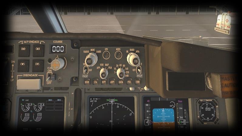
49 Autopilot Operation 1 Left COURSE Display and Rotary Used to select the desired VOR radial for the captain s EHSI. This works in conjunction with the VOR selected using the pilot s EHSI Control Panel. This switch is used in conjunction with the IAS / MACH Rotary and Display. 2 Auto Throttle Switch Use this switch to toggle the Auto Throttle on, or off. When Auto Throttle is engaged, the autopilot has command of the throttles, and will govern the airspeed according to the value indicated by the IAS / MACH Display. 3 C/O Toggle Toggles the IAS / MACH display units between Knots and Mach-number 4 IAS / MACH Display and Rotary When used in conjunction with the Speed Button, and Auto-Throttle, the autopilot will govern the speed according to this value. 5 VNAV Button VNAV (Vertical Navigation). The autopilot / autothrottle will follow the vertical components of your flight plan. 6 Heading Display and Rotary This display is used in conjunction with the HEADING Rotary. When Heading- Select mode is engaged, the autopilot will steer the aircraft according to the value displayed here. Use the Rotary Control outer ring to adjust the bank angle / rate of turn. Use the Rotary Control inner ring to adjust the heading. 7 LNAV Button LNAV (Lateral Navigation). The autopilot will follow the lateral components of your flight plan. 49
50 8 Altitude Display and Rotary Used in conjunction with the Altitude Hold Button and Vertical Speed Button. When Altitude Hold is engaged, the autopilot will immediately level-off, and the level-off altitude will be displayed here. When Vertical Speed mode is engaged, the autopilot will ascend, or descend at the desired rate, until reaching the altitude displayed here, at which point it will level-off. 9 Vertical Speed Display and Rotary When VS (Vertical Speed) Mode is engaged, the autopilot will govern the rate of ascent, or descent, according to this value. The CMD buttons are used to engage the autopilot, noting there are two separate and identical systems A, and B. Note that, after engaging the autopilot, the desired mode must still be selected subsequently. Systems A and B are normally engaged exclusively. However, when in auto-land mode, both are typically engaged together, to provide redundancy in case of failure. 10 A/P ENGAGE The CWS buttons are used to engage Control Wheel Steering mode, whereby the autopilot will allow the pilot to make inputs using the control wheel, after which it will hold the resulting attitude. CMD / A Engages Autopilot A CMD / B Engages Autopilot B CWS / A Engages Autopilot A in Control Wheel Steering mode CWS / B Engages Autopilot B in Control Wheel Steering mode 11 Right Course Display and Rotary Used to select the desired VOR radial for the first-officer s EHSI. This works in conjunction with the VOR selected using the first-officer s EHSI Control Panel. 12 First-officer s Flight Director Switch Use this switch to toggle the Flight Director display on, or off for the first-officer s EADI. The flight director computes and displays the proper pitch and bank angles required for the aircraft to follow the desired flight plan. The flight-crew can manually fly the aircraft according to the flight plan - by aligning the attitude indicator with the Flight Director pitch and bank command bars. 13 Autopilot Disengage Click this button to disengage the autopilot and return full manual control to the flight crew. 14 VS Button Click this button to engage Vertical Speed Mode. Used in conjunction with the auto-throttle, the autopilot will govern the rate of ascent, or descent, according to the value indicated by the Vertical Speed Display. 15 ALT Hold Button Click this button to engage Altitude Hold Mode. The autopilot will level-off and hold the current altitude. 16 VOR / LOC Button Click this button to engage VOR or Localizer Mode. The autopilot will steer the aircraft laterally to intercept and track the VOR radial, or ILS localizer that is selected via the active Nav radio. 50
51 17 APP Button User in conjunction with the auto-throttle and NAV-1 radio to activate a localizer or ILS approach. 18 HDG Select Button Click this button to engage Heading Mode. The autopilot will steer according to the Heading Display / EHSI heading bug. 19 LVL CHG Button Click this button to engage Vertical Speed Mode. Used in conjunction with the auto-throttle, the autopilot will maintain the current airspeed while ascending, or descending to the selected altitude. 20 Speed Button Click this button to engage Speed Mode. Used in conjunction with the autothrottle, the autopilot will maintain airspeed according to the IAS / MACH Display. 21 N1 Button (Not currently supported). In the real aircraft, this button causes the auto-throttles to advance to a pre-defined limit N1 (turbine) limit expressed using the FMC. 22 Pilot s Flight Director Switch Use this switch to toggle the Flight Director display on, or off for the first-officer s EADI. The flight director computes and displays the proper pitch and bank angles required for the aircraft to follow the desired flight plan. The flight-crew can manually fly the aircraft according to the flight plan - by aligning the attitude indicator with the Flight Director pitch and bank command bars. 51

52 Auto-Land This aircraft is capable of full auto-land, provided the ILS in use if CAT-3 approved (check this using the X-Plane map). Establish the aircraft first on a sensible intercept for both the localizer and glide-slope, and then follow this procedure: ARM the Speed Brakes Tune the ILS on both NAV1 and NAV2 receivers Set the ILS front course on both CRS1 and CRS2 selectors 52


53 Check both Flight Director switches (FD1 and FD2) are ON Engage autopilot A or B using the appropriate CMD button Arm APP mode While still above 1500 ft radar altitude, with approach mode active, engage the other autopilot (A or B) using the appropriate CMD button Below 1500 ft radar altitude, observe ROLLOUT and FLARE arm annunciations 53
54 Flight Planning Flight planning is the process of determining a route from origin to destination that considers fuel requirements, terrain avoidance, Air Traffic Control, aircraft performance, airspace restrictions and notices to airmen (NOTAMS). General information about flight plans is available on Wikipedia at Flight plans can be generated by onboard computers if the aircraft is suitably equipped. If not, simulation pilots may elect to use an online flight planner. A web search for the phrase Flight Planner will yield a great many options, many of which are free services. A good online flight planner will utilize the origin and destination airports, together with the aircraft type and equipment, the weather conditions, the chosen cruise altitude, known restrictions along the route, current NOTAMS, and other factors to generate a suitable flight plan. The waypoints incorporated into the flight plan can be subsequently input into the aircraft s Flight Management Computer (FMS), or Global Positioning System (GPS). Some online flight planners provide the option to save the plan as an X-Plane compatible file, with an fms extension. A saved flight plan can be loaded into the GPS or Flight Management Computer unit featured in the B It is recommended the pilot generate a flight plan for the chosen route before using the FMS or GPS units. Instructions for operating the Laminar Research FMS and GPS units can be found in separate (dedicated) manuals. 54
55 Fuel Calculation Note: All calculations here are based on the X-Plane B , and NOT the real-life B Differences may exist. Load Sheet Tables The tables below illustrate a series of hypothetical load-sheet scenarios. For these purposes, passengers are deemed to have an average weight of 165 lbs. and the aircraft will carry a flight crew of two pilots and six cabin-crew. These tables do not include ground operations. Add 500 lbs. of fuel for every 10-minutes of taxi-time. Flight Time (Minutes) T/O and Climb Fuel Cruise Fuel (lbs.) Total Fuel Left Wing Tank (lbs.) Right Wing Tank (lbs.) Center Tank (lbs.) PAX Fwd PAX Mid PAX Aft Cargo Fwd Cargo Aft Payload (lbs.) CG %MAC CG X-Plane (in.) 20 1,000 2,050 3,050 1,525 1, , ,000 4,100 5,100 2,550 2, , ,000 6,150 7,150 3,575 3, , ,000 8,200 9,200 4,600 4, , ,000 10,250 11,250 5,625 5, , ,000 12,300 13,300 6,650 6, , ,000 14,350 15,350 7,675 7, , ,000 16,400 17, , , ,000 18,450 19, ,500 2, , ,000 20,500 21, ,500 4, , ,000 22,550 23, ,500 6, , ,000 24,600 25, ,500 8, , ,000 26,650 27, ,500 10, , ,000 28,700 29, ,500 12, , ,000 30,750 31, ,500 14, , ,000 32,800 33, ,500 16, , ,000 34,850 35, ,500 18, , ,000 36,900 37, ,500 20, , ,000 38,950 39, ,500 22, , ,000 41,000 42, ,500 25, , ,000 43,050 44, ,500 27, ,
56 Flight Time (Minutes) T/O and Climb Fuel Cruise Fuel (lbs.) Total Fuel Left Wing Tank (lbs.) Right Wing Tank (lbs.) Center Tank (lbs.) PAX Fwd PAX Mid PAX Aft Cargo Fwd Cargo Aft Payload (lbs.) CG %MAC CG X-Plane (in.) 20 1,000 2,050 3,050 1,525 1, , ,000 4,100 5,100 2,550 2, , ,000 6,150 7,150 3,575 3, , ,000 8,200 9,200 4,600 4, , ,000 10,250 11,250 5,625 5, , ,000 12,300 13,300 6,650 6, , ,000 14,350 15,350 7,675 7, , ,000 16,400 17, , , ,000 18,450 19, ,500 2, , ,000 20,500 21, ,500 4, , ,000 22,550 23, ,500 6, , ,000 24,600 25, ,500 8, , ,000 26,650 27, ,500 10, , ,000 28,700 29, ,500 12, , ,000 30,750 31, ,500 14, , ,000 32,800 33, ,500 16, , ,000 34,850 35, ,500 18, , ,000 36,900 37, ,500 20, , ,000 38,950 39, ,500 22, , ,000 41,000 42, ,500 25, , ,000 43,050 44, ,500 27, ,
57 Flight Time (Minutes) T/O and Climb Fuel Cruise Fuel (lbs.) Total Fuel Left Wing Tank (lbs.) Right Wing Tank (lbs.) Center Tank (lbs.) PAX Fwd PAX Mid PAX Aft Cargo Fwd Cargo Aft Payload (lbs.) CG %MAC CG X-Plane (in.) 20 1,000 2,050 3,050 1,525 1, , ,000 4,100 5,100 2,550 2, , ,000 6,150 7,150 3,575 3, , ,000 8,200 9,200 4,600 4, , ,000 10,250 11,250 5,625 5, , ,000 12,300 13,300 6,650 6, , ,000 14,350 15,350 7,675 7, , ,000 16,400 17, , , ,000 18,450 19, ,500 2, , ,000 20,500 21, ,500 4, , ,000 22,550 23, ,500 6, , ,000 24,600 25, ,500 8, , ,000 26,650 27, ,500 10, , ,000 28,700 29, ,500 12, , ,000 30,750 31, ,500 14, , ,000 32,800 33, ,500 16, , ,000 34,850 35, ,500 18, , ,000 36,900 37, ,500 20, , ,000 38,950 39, ,500 22, , ,000 41,000 42, ,500 25, , ,000 43,050 44, ,500 27, ,
58 Flight Time (Minutes) T/O and Climb Fuel Cruise Fuel (lbs.) Total Fuel Left Wing Tank (lbs.) Right Wing Tank (lbs.) Center Tank (lbs.) PAX Fwd PAX Mid PAX Aft Cargo Fwd Cargo Aft Payload (lbs.) CG %MAC CG X-Plane (in.) 20 1,000 2,050 3,050 1,525 1, , ,000 4,100 5,100 2,550 2, , ,000 6,150 7,150 3,575 3, , ,000 8,200 9,200 4,600 4, , ,000 10,250 11,250 5,625 5, , ,000 12,300 13,300 6,650 6, , ,000 14,350 15,350 7,675 7, , ,000 16,400 17, , , ,000 18,450 19, ,500 2, , ,000 20,500 21, ,500 4, , ,000 22,550 23, ,500 6, , ,000 24,600 25, ,500 8, , ,000 26,650 27, ,500 10, , ,000 28,700 29, ,500 12, , ,000 30,750 31, ,500 14, , ,000 32,800 33, ,500 16, , ,000 34,850 35, ,500 18, , ,000 36,900 37, ,500 20, , ,000 38,950 39, ,500 22, , ,000 41,000 42, ,500 25, , ,000 43,050 44, ,500 27, ,
59 Flight Time (Minutes) T/O and Climb Fuel Cruise Fuel (lbs.) Total Fuel Left Wing Tank (lbs.) Right Wing Tank (lbs.) Center Tank (lbs.) PAX Fwd PAX Mid PAX Aft Cargo Fwd Cargo Aft Payload (lbs.) CG %MAC CG X-Plane (in.) 20 1,000 2,050 3,050 1,525 1, , ,000 4,100 5,100 2,550 2, , ,000 6,150 7,150 3,575 3, , ,000 8,200 9,200 4,600 4, , ,000 10,250 11,250 5,625 5, , ,000 12,300 13,300 6,650 6, , ,000 14,350 15,350 7,675 7, , ,000 16,400 17, , , ,000 18,450 19, ,500 2, , ,000 20,500 21, ,500 4, , ,000 22,550 23, ,500 6, , ,000 24,600 25, ,500 8, , ,000 26,650 27, ,500 10, , ,000 28,700 29, ,500 12, , ,000 30,750 31, ,500 14, , ,000 32,800 33, ,500 16, , ,000 34,850 35, ,500 18, , ,000 36,900 37, ,500 20, , ,000 38,950 39, ,500 22, , ,000 41,000 42, ,500 25, , ,000 43,050 44, ,500 27, ,
60 Flight Time (Minutes) T/O and Climb Fuel Cruise Fuel (lbs.) Total Fuel Left Wing Tank (lbs.) Right Wing Tank (lbs.) Center Tank (lbs.) PAX Fwd PAX Mid PAX Aft Cargo Fwd Cargo Aft Payload (lbs.) CG %MAC CG X-Plane (in.) 20 1,000 2,050 3,050 1,525 1, , ,000 4,100 5,100 2,550 2, , ,000 6,150 7,150 3,575 3, , ,000 8,200 9,200 4,600 4, , ,000 10,250 11,250 5,625 5, , ,000 12,300 13,300 6,650 6, , ,000 14,350 15,350 7,675 7, , ,000 16,400 17, , , ,000 18,450 19, ,500 2, , ,000 20,500 21, ,500 4, , ,000 22,550 23, ,500 6, , ,000 24,600 25, ,500 8, , ,000 26,650 27, ,500 10, , ,000 28,700 29, ,500 12, , ,000 30,750 31, ,500 14, , ,000 32,800 33, ,500 16, , ,000 34,850 35, ,500 18, , ,000 36,900 37, ,500 20, , ,000 38,950 39, ,500 22, , ,000 41,000 42, ,500 25, , ,000 43,050 44, ,500 27, ,

61 Setting the Weight, Balance and Fuel in X-Plane After calculating your fuel requirements (see Fuel Calculation) and referencing the Load Sheet Tables, you are ready to configure the weight, balance and fuel for your upcoming flight. Select the B from the flight menu, and click on the Customize button, followed by the Weight, Balance & Fuel button. Now input the Center of Gravity, Payload Weight, Fuel Weight (Fuel Tank 1) and Fuel Weight (Fuel Tank 2) and Fuel Weight (Fuel Tank 3). The example below is for the scenario highlighted in blue in the Load Sheet Tables. 61

62 Checklists The following check lists are designed with the convenience of the simulation pilot in mind and customized to the X-Plane B aircraft. These differ from those of the real aircraft. Pre-Flight Exterior Inspection A Pre-Flight Inspection should always precede flight in any aircraft. The purpose of this inspection is to ensure the aircraft is in a state of readiness for the upcoming flight. In X-Plane, a pre-flight inspection is not merely undertaken to simulate reality, but does in fact have real purpose, because the control surfaces of the aircraft interact directly with the airflow over and around them, just as in real life. As such, correct movement of all control surfaces is necessary for normal flight. Hold roll axis at full deflection. Visually check corresponding movement of ailerons and speed-brakes. 62


63 Hold pitch axis at full deflection. Visually check corresponding movement of elevators. Hold yaw axis at full deflection. Visually check corresponding movement of rudder. 63

64 Cold and Dark to Engine Start The following check list is a sub-set of the real procedures, and includes only the essential steps leading to engine start: PARKING BRAKE ON BATTERY MASTER ON STANDBY POWER ON 64
65 GROUND POWER ON APU START Move switch to START, then release to ON. Wait for Blue Light illumination on APU panel. APU GENERATOR 1 ON APU GENERATOR 2 ON 65
66 GROUND POWER OFF AFT & FWD FUEL PUMPS 1 ON AFT & FWD FUEL PUMPS 2 ON APU BLEED - ON 66
67 HYDRAULIC PUMPS A & B ON ELECTRICAL PUMPS A & B ON ENGINE 1 GRD (GROUND) 67


68 Wait until OIL FILTER BYPASS And LOW OIL PRESSURE extinguish. ENGINE 1 FUEL CONTROL LEVER UP (ON) 68

69 ENGINE 2 GRD (GROUND) Wait until OIL FILTER BYPASS And LOW OIL PRESSURE extinguish. 69
 APU BLEED -")
70 ENGINE 2 FUEL CONTROL LEVER UP (ON) APU BLEED - OFF 70

71 APU OFF 71

72 Before Taxi SEATBELT SIGN - ON ELEVATOR TRIM SET FOR TAKEOFF (+ 10 Degrees) 72
 See: Assigning peripheral")
73 FLAPS SET (5 Degrees) FLIGHT CONTROLS CHECKED (Pitch / Roll / Yaw) See: Assigning peripheral devices 73
74 TAXI LIGHTS - ON TRANSPONDER ALT OFF PARKING BRAKE OFF 74
")
75 Before Takeoff ALTIMETER - SET TRANSPONDER ALT ON LANDING LIGHTS ON (TAXI LIGHTS OFF) 75

76 After Takeoff LANDING GEAR UP FLAPS RETRACTED THRUST SET AS REQUIRED 76
77 Cruise SEATBELT SIGN - OFF WING / LANDING LIGHTS - OFF ALTIMETER - SET 77
78 Before Landing SEATBELT SIGN - ON ALTIMETER - SET WING / LANDING LIGHTS - ON 78

79 Landing SPEED BRAKES SET AS REQUIRED FLAPS SET AS REQUIRED LANDING GEAR DOWN 79

80 After Landing FLAPS RETRACTED SPEED BRAKES RETRACTED WING / LANDING LIGHTS - OFF 80
81 TRANSPONDER ALT OFF 81

82 Parking PARKING BRAKE ON SEATBELT SIGN - OFF TRANSPONDER STBY (Standby) 82

83 FUEL CONTROL LEVERS DOWN (OFF) HYDRAULIC PUMPS A & B OFF ELECTRICAL PUMPS A & B OFF 83
X-Plane 11 MD-82. Pilot s Operating Manual. Disclaimer. Distribution. Author: Julian Lockwood Copyright: Laminar Research 2018
 Pilot s Operating Manual Author: Julian Lockwood (julian@x-plane.com) Copyright: Laminar Research 2018 X-Plane 11 MD-82 Disclaimer The information contained in this document is for simulation use only,
X-Plane 11 King Air C90B
 Pilot s Operating Manual Author: Julian Lockwood (julian@x-plane.com) Copyright: Laminar Research 2017 X-Plane 11 King Air C90B Disclaimer The information contained in this document is for simulation use
OVERHEAD PANEL PROCEDURES FLASH CARDS
 OVERHEAD PANEL PROCEDURES FLASH CARDS Boeing 737-800 A supplement to the procedures and checklists publication, Flying the Boeing 737-800 NG Greg Whiley Aussie Star Flight Simulation ELECTRICAL POWER UP
by Greg Whiley Aussie Star Flight Simulation
 Flying the BAe 146 200/300 Version 2 by Greg Whiley Aussie Star Flight Simulation INTENTIALLY LEFT BLANK Greg Whiley Aussie Star Flight Simulation 2 Version Date Revision Version 1.0 25 June 2014 Original
X-Plane 11 Cessna 172
 Pilot s Operating Manual Author: Julian Lockwood (julian@x-plane.com) Copyright: Laminar Research 2017 X-Plane 11 Cessna 172 Disclaimer The information contained in this document is for simulation use
David s Flight Simulator Operations Manual
 DPW Solutions David s Flight Simulator Operations Manual Draft 0.2 David Woolterton Update 10/5/2016 Table of Contents Pre-Start Checklist... 2 Startup Checklist... 3 Before Taxi Checklist... 3 Taxi Checklist...
Automatic Flight Chapter 4
 Automatic Flight Chapter 4 Table of Contents Section 0 4.0 Automatic Flight-Table of Contents Controls and Indicators................................ 4.10.1 Mode Control Panel (MCP).............................
Examen Teórico sobre Habilitación de Tipo B (Última actualización: Septiembre 2016)
") DIRECCIÓN GENERAL DE AERONÁUTICA CIVIL DEPARTAMENTO SEGURIDAD OPERACIONAL SUBDEPARTAMENTO LICENCIAS Examen Teórico sobre Habilitación de Tipo B-737-300 (Última actualización: Septiembre 2016) Materia:
DIRECCIÓN GENERAL DE AERONÁUTICA CIVIL DEPARTAMENTO SEGURIDAD OPERACIONAL SUBDEPARTAMENTO LICENCIAS Examen Teórico sobre Habilitación de Tipo B-737-300 (Última actualización: Septiembre 2016) Materia:
EXAMEN POR MATERIAS PARA USO DE LOS POSTULANTES A LA HABILITACIÓN DE TIPO EN MATERIAL B733. ENERO 2018
 DEPARTAMENTO SEGURIDAD OPERACIONAL SUBDEPARTAMENTO LICENCIAS SECCIÓN EVALUACIONES EXAMEN POR MATERIAS PARA USO DE LOS POSTULANTES A LA HABILITACIÓN DE TIPO EN MATERIAL B733. ENERO 2018 Cantidad de Preguntas
Cessna Citation XLS - Electrical
 GENERAL Electrical power for the Citation XLS comes primarily from DC sources originating with the starter/ generators, the Auxiliary Power Unit (APU) or the battery. A receptacle below the left engine
Dassault Falcon 50 Microsoft Flight Simulator 2004
 Dassault Falcon 50 Microsoft Flight Simulator 2004 Model and bitmaps Yannick Lavigne Custom gauge programming Fred Banting Flight dynamics Rob Young and Eric Dantes. Foto: Gerry Stegmeier Foto: Dassault
REFERENCE: 2861 wings 2044 trunk 4904 total BEW 10,655 BOW 11,185 Max Useful load 5115 MLanding ZFW FUEL BURNS 11min min min
 REFERENCE: 2861 wings 2044 trunk 4904 total BEW 10,655 BOW 11,185 Max Useful load 5115 MLanding 15700 ZFW 13000 FUEL BURNS 11min 357 27min 730 36 min 940 58min 1453 1:17 1800 2:20 2933 2:46 3283 3:00 3600
COCKPIT AND SYSTEMS 7-1. Table of Contents
 COCKPIT AND SYSTEMS 7-1 Table of Contents Abbreviations Table...5 Air Systems...7 Controls and Indicators...7 Bleed Air Controls and Indicators...7 Air Conditioning Controls and Indicators (737-600/700)...8
B737 NG Anti Ice & Rain
 B737 NG Anti Ice & Rain Introduction Thermal anti-icing (TAI), electrical anti-icing, and windshield wipers are the systems provided for ice and rain protection. The anti-ice and rain systems include:
FLIGHT CONTROLS SYSTEM
 FLIGHT CONTROLS SYSTEM DESCRIPTION Primary flight control of the aircraft is provided by aileron, elevator and rudder control surfaces. The elevator and rudder control surfaces are mechanically operated.
PA GURW (December 30, 2000) PRE-START. Langley Flying School. Airspeeds (MPH) for Safe Operation. Cockpit Checks
 PRE-START. Langley Flying School. Airspeeds (MPH) for Safe Operation. Cockpit Checks") Langley Flying School PA-34-200 GURW (December 30, 2000) Airspeeds (MPH) for Safe Operation V y (all weights) 105 V x (all weights) 90 En Route Climb 120 V mc 80 V yse 105 V xse 93 V r 80 V r (25 Flaps)
Langley Flying School PA-34-200 GURW (December 30, 2000) Airspeeds (MPH) for Safe Operation V y (all weights) 105 V x (all weights) 90 En Route Climb 120 V mc 80 V yse 105 V xse 93 V r 80 V r (25 Flaps)
The engines are designed to use 100/130 octane fuel. If not available use next higher grade. - 1
 PNEUMATIC SYSTEM The aircraft has a dual pneumatic system. In case of failure of either pneumatic pump, the system will automatically select the operative source. (Inoperative source will be indicated
Cessna 172P PPL Checklist Page 1
 Cessna 172P PPL Checklist 06-08-2017 Page 1 Cessna 172P PPL Checklist 06-08-2017 Page 2 Checklist Items Informational Items Critical Memory Items PREFLIGHT COCKPIT CHECK (DO-LIST) Pitot Cover -- REMOVE
HU-16 Albatross USER MANUAL. Virtavia HU-16 Albatross DTG Steam Edition Manual Version 1.0
 HU-16 Albatross USER MANUAL 0 Introduction The Grumman HU-16 Albatross is a twin-engine amphibious flying boat. First flown in 1949, the HU-16 underwent a number of modifications and improvements over
FIRST FLYING TECHNIQUES COCKPIT PREPARATION STARTUP TAXI
 1. Introduction FIRST FLYING TECHNIQUES COCKPIT PREPARATION STARTUP TAXI We aim to teach and demonstrate how to operate a general aviation aircraft and show some basic techniques and manoeuvres that every
AIRPLANE FLIGHT MANUAL AQUILA AT01 AIRPLANE FLIGHT MANUAL - SUPPLEMENT AVE28 GLASS COCKPIT. equipped with ASPEN EFD1000 PFD
 SECTION 9 AIRPLANE FLIGHT MANUAL - SUPPLEMENT AVE28 GLASS COCKPIT equipped with ASPEN EFD1000 PFD This AFM supplement is applicable and must be inserted into Section 9 of the Airplane Flight Manual when
POWER ON CHECK LIST COCKPIT PREPARATION
 Normal Check List DASH 8-402 1 POWER ON CHECK LIST CIRCUIT BREAKERS... CHECKED BATTERY MASTER... ON BATTERIES... ON MAIN BUS TIE... TIED EXTERNAL POWER... AS REQUIRED APU... AS REQUIRED BATTERIES & BATTERY
Interior Pre Flight Documents: Check Control Wheel Lock: Remove Flight Controls: Check Instruments: Check for Damage Switches: Verify All Off Master
 Interior Pre Flight Documents: Check Control Wheel Lock: Remove Flight Controls: Check Instruments: Check for Damage Switches: Verify All Off Master Switch ALT/BAT: On Fuel Gauge: Check Quantity Flaps:
Fokker 50 - Limitations GENERAL LIMITATIONS MASS LIMITATIONS. Page 1. Minimum crew. Maximum number of passenger seats.
 GENERAL LIMITATIONS Minimum crew Cockpit: Two pilots Maximum number of passenger seats Sixty-two (62) Maximum operating altitudes Maximum operating pressure altitude: Maximum take-off and landing pressure
V - Speeds. RV-10 V fe Flaps Speeds Trail (0 deg) Half (15 deg) Full (30 deg) 122 kias 96 kias. 80 kias
 Half (15 deg) Full (30 deg) 122 kias 96 kias. 80 kias") RV-10 Check List V - Speeds RV-10 V fe Flaps Speeds Trail (0 deg) Half (15 deg) Full (30 deg) 122 kias 96 kias 87 kias V s1 Stall (Flap Up) 60 kias V s0 Stall (Flap 40 deg) 55 kias Best Glide 80 kias V
RV-10 Check List V - Speeds RV-10 V fe Flaps Speeds Trail (0 deg) Half (15 deg) Full (30 deg) 122 kias 96 kias 87 kias V s1 Stall (Flap Up) 60 kias V s0 Stall (Flap 40 deg) 55 kias Best Glide 80 kias V
Convair XB-46 USER MANUAL. Virtavia XB-46 Manual Version DTG 1.0
 Convair XB-46 USER MANUAL 0 Introduction For the 1944 jet bomber competition, Consolidate Vultee (which became Convair) offered their model 109, which featured four Allison J-35-C-3 jet engines slung under
AIRPLANE GENERAL Exterior REV 3, May 03/05
 Vol. 1 01--20--1 AIRPLANE GENERAL Exterior REV 3, May 03/05 24 ft 1 in (7.34 m) 5ft1in(1.55m) 10 ft 7 in (3.23 m) 6ft4in (1.93 m) 81 ft 6 in (24.85 m) 9ft6in(2.89m) 8ft10in (2.69 m) 36 ft 4 in (11.07 m)
AIRCRAFT GENERAL KNOWLEDGE (2) INSTRUMENTATION
 INSTRUMENTATION") 1 The purpose of the vibrating device of an altimeter is to: A reduce the effect of friction in the linkages B inform the crew of a failure of the instrument C allow damping of the measurement in the unit
1 The purpose of the vibrating device of an altimeter is to: A reduce the effect of friction in the linkages B inform the crew of a failure of the instrument C allow damping of the measurement in the unit
Introduction. I. Introduction Abbreviations Icon Legend Resources
 Introduction Management Reference Guide I. Introduction Abbreviations Icon Legend Resources II. Takeoff Performance Computation Limitation Legend Corrections Maximum Takeoff Performance (Full Thrust Method)
Boeing B-47 Stratojet USER MANUAL. Virtavia B-47E Stratojet DTG Steam Edition Manual Version 2
 Boeing B-47 Stratojet USER MANUAL 0 Introduction The Boeing B-47 was the first swept-wing multi-engine bomber in service with the USAF. It was truly a quantum leap in aviation history, and is the forerunner
The Straight Word. Cessna 208 Caravan 208 Caravan I & 208B Grand Caravan Series
 The Straight Word Cessna 208 Caravan 208 Caravan I & 208B Grand Caravan Series I. FLIGHT PROCEDURES: COCKPIT PREPARATION Fuel Tank Selectors Ignition Switch Heading Bug HSI Course Indicator Altimeters
At all times use approved company publications and aircraft manufacturer manuals as sole reference for procedures and data!
 Disclaimer These notes have not been approved by any aviation administration, by any airline nor by the aircraft manufacturer to whom it refers. At all times use approved company publications and aircraft
CESSNA 182 CHECKLIST. LEFT WING Trailing Edge 1. Aileron CHECK freedom of movement and security
 CESSNA 182 CHECKLIST PRE-FLIGHT INSPECTION CABIN 1. Pilot s Operating Handbook AVAILABLE IN THE AIRPLANE (A.R.R.O.W.E) 2. Landing Gear Lever DOWN 3. Control Wheel Lock REMOVE 4. Ignition Switch OFF 5.
Expanded Flight Checklist Cessna 152
 OUTSIDE CHECK INSIDE CABIN 1 Magnetos... OFF 2 Mixture... IDLE CUT OFF 3 Master switch... ON 4 Fuel quantity... CHECKED 5 Master switch... OFF OUTSIDE CABIN 1 Left wing... CHECKED Surface condition Flap
N955DK RV-8A David B. Kumhyr. N955DK Version 05Nov04 RV-8A
 N955DK RV-8A David B. Kumhyr Operating Speeds Reference VREF Flight Regime Kts Mph Vso Stall, dirty (gross)... Stall, dirty (solo).. 50 58 Vs.. Stall, clean (gross)... Stall, clean (solo). 55 63 Vr.. Rotation.
DIAMOND DA40 PILOTS MANUAL
 DIAMOND DA40 PILOTS MANUAL INTRODUCTION THIS IS THE SLEEK AND FUTURISTIC DIAMOND STAR DA40 XLS BY DIAMOND AIRCRAFT CORPORATION. THE DIAMOND STAR FEATURES 4 SEATS, AND OPTIONAL EXPANDED REAR CARGO AREA,
E-2C Hawkeye USER MANUAL. Virtavia E-2C Hawkeye Manual Version 1.0
 E-2C Hawkeye USER MANUAL 0 Introduction The E-2C is an all-weather twin turboprop carrier-borne early warning aircraft that is also used for land-based operations. Its APS-139 radar, mounted in a 24 ft
IntelliFlight 2100 Programmer/Computer PN Software Mod Code L or Later WAAS Capable Pilot s Operating Handbook
 IntelliFlight 2100 Programmer/Computer PN 01304 Software Mod Code L or Later WAAS Capable Pilot s Operating Handbook NAV VS 500 ALT 12 5 00 List of Effective Pages * Asterisk indicates pages changed, added,
North American F-86F Sabre USER MANUAL. Virtavia F-86F Sabre DTG Steam Edition Manual Version 1
 North American F-86F Sabre USER MANUAL 0 Introduction The F-86 Sabre was a natural replacement for the F-80 Shooting Star. First introduced in 1949 for the United States Air Force, the F-86 featured excellent
Takeoff Flaps UP 2000
 Takeoff Flaps UP 2000 30 60 75 80 85 V1 Gear UP Flap Position Indicator blanked 10 seconds after flaps UP Asymmetry Protection Near Zero Yaw Automatic unlock all surfaces (maintenance) Speedbrakes auto
COLUMBIA 350 EMERGENCY PROCEDURES
 COLUMBIA 350 EMERGENCY PROCEDURES TABLE OF CONTENTS EMERGENCY PROCEDURES LANDING AND TAKEOFF Engine Failure During Takeoff...1 Engine Failure Immediately After Takeoff...1 Engine Failure During Climb to
1. Aircraft General (0 Hours 39 minutes) 2. Doors (0 Hours 33 minutes) 3. EFIS (2 Hours 55 minutes) 4. Exterior Lighting (0 Hours 24 minutes)
 2. Doors (0 Hours 33 minutes) 3. EFIS (2 Hours 55 minutes) 4. Exterior Lighting (0 Hours 24 minutes)") Course: CRJ900 (Pilot) Delivery Formats: Web Based or Portable Classroom Number of modules: 26 Estimated Course Time: 36 Hours 16 minutes The following topics are included in this CRJ900 (Pilot) CBT/WBT
Course: CRJ900 (Pilot) Delivery Formats: Web Based or Portable Classroom Number of modules: 26 Estimated Course Time: 36 Hours 16 minutes The following topics are included in this CRJ900 (Pilot) CBT/WBT
MAJESTIC Q400 SHARED COCKPIT FLOWS CHECKLISTS MULTIPLAYER OPERATIONS.
 PRE LOAD IN Agree on Ports, Share IP and select who will be doing W&B. INITIAL LOAD IN On 1 System transfer Weight and Balance to Simulator Pause Simulation Save Flight as normal FSX Flight Transfer Save
King Air B90. Speeds (KIAS)
") King Air B90 Speeds (KIAS) V MCA 92 V SSE (101) Derived from C90 V X 101 V Y 114 Down to 103 @ 30 000 V XSE 101 V YSE 110 Down to 101 @ 24 000 V A 169 V R 92 V 1 101 V MO 208 V FE 174 35% 130 100% V LE
King Air B90 Speeds (KIAS) V MCA 92 V SSE (101) Derived from C90 V X 101 V Y 114 Down to 103 @ 30 000 V XSE 101 V YSE 110 Down to 101 @ 24 000 V A 169 V R 92 V 1 101 V MO 208 V FE 174 35% 130 100% V LE
CESSNA SECTION 4. Unless otherwise noted, the following speeds are based on a maximum weight of 2550 pounds and may be used for any lesser weight.
 CESSNA SECTION 4 INTRODUCTION Section 4 provides procedures and amplified instructions for normal operations using standard equipment. Normal procedures associated with optional systems can be found in
Flight Checklist for Normal Operations Massgebend ist das AFM (Parameters, Restrictions, Emergency, etc.)
") Flight Checklist for Normal Operations Massgebend ist das AFM (Parameters, Restrictions, Emergency, etc.) Jan18 1 COCKPIT PREPARATION BEFORE STARTING ENGINE 1 Aircraft + Cockpit Inspection COMPLETED 1
Flight Checklist for Normal Operations Massgebend ist das AFM (Parameters, Restrictions, Emergency, etc.) Jan18 1 COCKPIT PREPARATION BEFORE STARTING ENGINE 1 Aircraft + Cockpit Inspection COMPLETED 1
ifly Jets: The 737NG Quick Reference Handbook Revision Number: 3 Revision Date: July 26, 2010
 ifly Jets: The 737NG ifly Jets: The 737NG Revision Number: 3 Revision Date: July 26, 2010 http://www.iflysimsoft.com/ The ifly Developer Team WARNING This manual is only used for understanding the functionalities
A310 MEMORY ITEMS Last Updated: 20th th October 2011
 A310 MEMORY ITEMS Last Updated: 20th th October 2011 1. Emergency Descent: Crew Oxygen Mask ON Crew Communication (Headsets) Establish Turn Initiate Descent Initiate o It is recommended to descend with
IN-FLIGHT CHECK LIST B-17 Technical Session for Flight Engineers 11/18/2017 (with REVISION)
") IN-FLIGHT CHECK LIST B-17 Technical Session for Flight Engineers 11/18/2017 (with REVISION) Check Lists became an integral part of aviation following the tragic loss of Boeing 299 the prototype for the
IN-FLIGHT CHECK LIST B-17 Technical Session for Flight Engineers 11/18/2017 (with REVISION) Check Lists became an integral part of aviation following the tragic loss of Boeing 299 the prototype for the
AIRPLANE OPERATIONS MANUAL SECTION 2-15
 SECTION 2-15 TABLE OF CONTENTS Block General... 2-15-05..01 Bleed Air Thermal Anti-Icing System... 2-15-10..01 Wing, Stabilizer and Engine Anti-icing Valves Operational Logic... 2-15-10..04 EICAS Messages...
NORMAL PROCEDURRES CHECKLIST PA T SENECA II PREFLIGHT CHECK INSIDE CABIN OUTSIDE CABIN
 NORMAL PROCEDURRES CHECKLIST PA-34-200T SENECA II PREFLIGHT CHECK INSIDE CABIN Avionics Master Switch -- OFF Landing Gear Control. -- DOWN Mixture Controls -- IDLE/CUTOFF Ignition Switches -- OFF Master
ENGINE GROUND RUNNING
 B737 600/700/800/900 (CFM 56) ENGINE GROUND RUNNING Guide and Reference Sheets This publication is for TRAINING PURPOSES ONLY. This information is accurate at the time of completion. No update service
The cockpit. UFCD Upfront control display. Head up display. Right DDI - Digital display indicator. Left DDI - Digital display indicator
 Super Hornet The cockpit Head up display Left DDI - Digital display indicator Fuel gauge / engine gauge Landing gear lever UFCD Upfront control display Right DDI - Digital display indicator HUD settings
The most important thing we build is trust. HeliSAS Technical Overview
 The most important thing we build is trust HeliSAS Technical Overview HeliSAS Technical Overview The Genesys HeliSAS is a stability augmentation system (SAS) and two-axis autopilot that provides attitude
CHECKLIST 1969 CESSNA 172-K. NOTE: Verify all information with airplane's POH
 CHECKLIST 1969 CESSNA 172-K NOTE: Verify all information with airplane's POH PRE-FLIGHT INSPECTION 1 CABIN 1 A.R.R.O.W. CHECK Airworthiness Cert. In Clear View Registration In Clear View Radio License
Flight Training Device ATS-B737NG Appendix B) Components Description
 Components Description") Model Serial Number Tail Number ATS-B737NG Operator Setup and instrument description of the Advanced Training System (ATS) B737NG, which includes the following sections, modules and instruments to simulate
Model Serial Number Tail Number ATS-B737NG Operator Setup and instrument description of the Advanced Training System (ATS) B737NG, which includes the following sections, modules and instruments to simulate
CESSNA 172S NAV III VFR CHECKOUT POH EXAMINATION (Based on N1129K, serial no. 172S revised 10/05/06)
") INTRODUCTION, POH CESSNA 172S NAV III VFR CHECKOUT POH EXAMINATION (Based on N1129K, serial no. 172S10315 - revised 10/05/06) 1. Rate of climb at sea level: 2. Service ceiling: 3. Takeoff performance,
INTRODUCTION, POH CESSNA 172S NAV III VFR CHECKOUT POH EXAMINATION (Based on N1129K, serial no. 172S10315 - revised 10/05/06) 1. Rate of climb at sea level: 2. Service ceiling: 3. Takeoff performance,
Jump to Table of Contents
 Jump to Table of Contents PIPER AIRCRAFT CORPORATION PA-28R-201, CHEROKEE ARROW III SECTION 3 EMERGENCY PROCEDURES 3.3 EMERGENCY PROCEDURES CHECK LIST ENGINE FIRE DURING
Checklist Robin DR40
 Flight Checklist for Normal Operations Massgebend ist das AFM (Parameters, Restrictions, Emergency, etc.) Jan 18 1 COCKPIT PREPARATION BEFORE STARTING ENGINE 1 Aircraft + Cockpit Inspection COMPLETED 1
B777. Electrical DO NOT USE FOR FLIGHT
 B777 Electrical DO NOT USE FOR FLIGHT 6.10 Electrical-Controls and Indicators Electrical Panel [IFE/PASS SEATS and CABIN/UTILITY switches basic with C/L 350] 1 2 IFE/PASS CABIN/ SEATS UTILITY 3 11 APU
Vso 61. Vs1 63. Vr 70. Vx 76. Vxse 78. Vy 89. Vyse. 89 (blue line) Vmc. 61 (radial redline) Vsse 76. Va 134) Vno 163
 Vmc. 61 (radial redline) Vsse 76. Va 134) Vno 163") PA34-200T Piper Seneca II Normal procedures V-speeds Knots Vso 6 Vs 63 Vr 70 Vx 76 Vxse 78 Vy 89 Vyse Vmc 89 (blue line) 6 (radial redline) Vsse 76 Va 2-36(@4507lbs 34) Vno 63 Vfe 38 (0*)/2(25*)/07(40*)
PA34-200T Piper Seneca II Normal procedures V-speeds Knots Vso 6 Vs 63 Vr 70 Vx 76 Vxse 78 Vy 89 Vyse Vmc 89 (blue line) 6 (radial redline) Vsse 76 Va 2-36(@4507lbs 34) Vno 63 Vfe 38 (0*)/2(25*)/07(40*)
I. DISPATCH PLANNING & AIRCRAFT EXTERIOR CHECK
 SCHODACK AVIATION Page 1 of 10 I. DISPATCH PLANNING & AIRCRAFT EXTERIOR CHECK 1. Flight Planning 1. Aircraft requirements & preparation: Required aircraft documents: Airworthiness Certificate Registration
Section 1: List of Configurations Currently Approved:
 Section 1: List of Configurations Currently Approved: 1. Configuration: TD2 BASIC-Standard - Single Engine, Land, Optional Fixed or Retractable Gear, Optional Fixed Pitch or Constant Speed Propeller, Optional
Flight checklist for normal operations Massgebend ist das AFM (parameters, restrictions, emergency, etc.)
") JAN13 1 Flight checklist for normal operations Massgebend ist das AFM (parameters, restrictions, emergency, etc.) Cockpit preparation before starting engine 1 Aircraft + Cockpit inspection completed (according
JAN13 1 Flight checklist for normal operations Massgebend ist das AFM (parameters, restrictions, emergency, etc.) Cockpit preparation before starting engine 1 Aircraft + Cockpit inspection completed (according
OPERATIONS MANUAL FTO SECTION : 06.04
 06.04.08. OO-WIK SECTION : 06.04 PARTENAVIA OO-WIK PAGE : 1 PRE ENTRY PITOT COVER - REMOVE SNOW / ICE CHECK AIRCRAFT NOSE INTO WIND AIRCRAFT WEIGHT & BALANCE WITHIN LIMITS EXTERNAL (COCKPIT FIRST) PARK
LOG OF REVISIONS. Model G58 Baron (Serials TH-2125 and After) Pilot s Operating Handbook and FAA Approved Airplane Flight Manual
 Pilot s Operating Handbook and FAA Approved Airplane Flight Manual") LOG OF REVISIONS Model G58 Baron (Serials TH-2125 and After) Pilot s Operating Handbook and FAA Approved Airplane Flight Manual Revision A12 - May, 2015 Title Page LOEP LOR Section 1 All Reformatted to
LOG OF REVISIONS Model G58 Baron (Serials TH-2125 and After) Pilot s Operating Handbook and FAA Approved Airplane Flight Manual Revision A12 - May, 2015 Title Page LOEP LOR Section 1 All Reformatted to
CHAPTER 1 AIRCRAFT GENERAL
 CHAPTER 1 AIRCRAFT GENERAL INTRODUCTION This manual provides a description of the major airframe and engine systems in the Cessna Citation Mustang (Figure 1-1). This material does not supersede, nor is
F-5E Tiger II USER MANUAL. Virtavia F-5E Tiger II DTG Steam Edition Manual Version 2.0
 F-5E Tiger II USER MANUAL 0 Introduction The F-5E Tiger II is an improved version of the original F-5 Freedom Fighter that entered service with the US Military in the early 1960s. It is a lightweight,
RFC Dallas, Inc. AIRCRAFT QUESTIONNAIRE (9/25/2016) "A Safe Pilot Knows His Equipment"
 A Safe Pilot Knows His Equipment") RFC Dallas, Inc. AIRCRAFT QUESTIONNAIRE (9/25/2016) "A Safe Pilot Knows His Equipment" NAME: Date: Aircraft: Cessna 182Q Registration Number: N631S Serial Number: The purpose of this questionnaire is to
RFC Dallas, Inc. AIRCRAFT QUESTIONNAIRE (9/25/2016) "A Safe Pilot Knows His Equipment" NAME: Date: Aircraft: Cessna 182Q Registration Number: N631S Serial Number: The purpose of this questionnaire is to
Cirrus SR20 Microsoft Flightsimulator 2002
 Cirrus SR20 Microsoft Flightsimulator 2002 Aircraft and Panel : Günter Kraemer Werner Schott Günter Kraemer Switzerland Germany w.schott@abbts.ch guenter@kraemerg.de Page 12 Page 1 Other simulator checklists
Cessna 172 Skyhawk. Aircraft Checklist Models: R & S
 Cessna 172 Skyhawk Aircraft Checklist Models: R & S This is an abbreviated checklist. Most explanatory items, notes cautions and warnings have been omitted for brevity. Procedures in red/bold text in this
2. What type and size (hp) engine does the airplane have? Lycoming O540-JC35D rated at 235 BHP at 2400 RPM
 engine does the airplane have? Lycoming O540-JC35D rated at 235 BHP at 2400 RPM") This quiz will help test your knowledge of the POH and the systems and equipment in CR-182 N133BW. In preparation for your checkout flight, answer all of the following questions as thoroughly as possible
This quiz will help test your knowledge of the POH and the systems and equipment in CR-182 N133BW. In preparation for your checkout flight, answer all of the following questions as thoroughly as possible
DASSAULT AVIATION Proprietary Data
 F2000EX EASY 02-33-00 CODDE 1 PAGE 1 / 2 TABLE OF CONTENTS 02-33 02-33-00 TABLE OF CONTENTS 02-33-05 GENERAL Introduction Sources 02-33-10 DESCRIPTION General Cockpit lights Cabin lights Servicing lights
Flight Training Device ATS-B737 MAX 8 Appendix B) Components Description
 Components Description") Model Serial Number Tail Number ATS-B737 MAX 8 Operator Setup and instrument description of the Advanced Training System (ATS) B737 MAX 8, which includes the following sections, modules and instruments
Model Serial Number Tail Number ATS-B737 MAX 8 Operator Setup and instrument description of the Advanced Training System (ATS) B737 MAX 8, which includes the following sections, modules and instruments
PA , Model E Normal Checklist (04/15/11)
") PA-23-250, Model E Normal Checklist (04/15/11) Key Airspeeds IAS-MPH V NE 249 V NO 198 V LO/LE 150 V A (At max gross weight.) 149 Speed for single engine cruise. 138 V FE Quarter Flaps 160 Half Flaps 140
PA-23-250, Model E Normal Checklist (04/15/11) Key Airspeeds IAS-MPH V NE 249 V NO 198 V LO/LE 150 V A (At max gross weight.) 149 Speed for single engine cruise. 138 V FE Quarter Flaps 160 Half Flaps 140
24 ELECTRICAL DC ELECTRICAL SYSTEM DESCRIPTION
 24 ELECTRICAL DC ELECTRICAL SYSTEM DESCRIPTION The Direct Current electrical system provides power to most equipment through an electrical bus system. The power may be supplied from one of three sources:
Piper Archer II (PA )
") 1. Oil... 6-8 qts, Cap Secure CABIN 1. POH & Documents.. Check Available 2. Magneto Switch...... OFF 3. Pitot/Static Drains... Push to Drain 4. Avionics/Electrical Switches... OFF 5. Master Switch. ON
1. Oil... 6-8 qts, Cap Secure CABIN 1. POH & Documents.. Check Available 2. Magneto Switch...... OFF 3. Pitot/Static Drains... Push to Drain 4. Avionics/Electrical Switches... OFF 5. Master Switch. ON
Document No. ST-931-RFM-0001
 275 Palos Verdes Dr. North Document No. ST-931-RFM-1 FAA APPROVED Rotorcraft Flight Manual Supplement to the Robinson R44 Pilot s Operating Handbook and FAA Approved Rotorcraft Flight Manual HeliSAS Aircraft
DASSAULT AVIATION Proprietary Data
 F900EX EASY 02-27-00 CODDE 1 PAGE 1 / 2 TABLE OF CONTENTS 02-27 02-27-00 TABLE OF CONTENTS 02-27-05 GENERAL Introduction Flight control sources Primary and secondary flight controls 02-27-10 DESCRIPTION
AIRCRAFT GENERAL KNOWLEDGE (2) INSTRUMENTATION
 INSTRUMENTATION") 1 The purpose of the vibrating device of an altimeter is to: A reduce the effect of friction in the linkages B inform the crew of a failure of the instrument C allow damping of the measurement in the unit
1 The purpose of the vibrating device of an altimeter is to: A reduce the effect of friction in the linkages B inform the crew of a failure of the instrument C allow damping of the measurement in the unit
NORMAL CHECKLIST ATTENTION!
 Avion Training CHECKLIST Normal Checklist CESSNA 172R / TC-STS Cessna 172 R TC-STS NORMAL CHECKLIST ATTENTION! DO NOT STOW THIS CHECKLIST IN DIRECT SUNLIGHT Avion Training - Doc.nr. 212 Revision 1 / 02022018
INDEX. Preflight Inspection Pages 2-4. Start Up.. Page 5. Take Off. Page 6. Approach to Landing. Pages 7-8. Emergency Procedures..
 INDEX Preflight Inspection Pages 2-4 Start Up.. Page 5 Take Off. Page 6 Approach to Landing. Pages 7-8 Emergency Procedures.. Page 9 Engine Failure Pages 10-13 Propeller Governor Failure Page 14 Fire.
Com Active/Standby Frequency Switch. C om Active/Standby Frequencies. Terrain. Flight Plan. Button. Button
 ALABEO GNS530 Nav Active/Standby Frequency Switch Com Active/Standby Frequency Switch C om Active/Standby Frequencies Zoom In/Out Button Nav Active/Standby Frequencies On/Off Button Direct To Button Nav1
Vr V STANDARD EQUIPMENT LIST
 Vr V5.02.09 STANDARD EQUIPMENT LIST IMPORTANT NOTE: this document is a general description of the aircraft equipment only. It is not a technical document and is to be used only for the purpose of generally
Best Glide 75 kias (Max Gross)
") CESSNA 172XP CHECKLIST PREFLIGHT (Interior) 1. ACFT DOCS / INSPECTIONS--------CHECK 2. TACH TIME-----------------------------RECORD 3. CONTROL LOCK---------------------REMOVE 4. ELEVATOR / RUDDER TRIM------------
CESSNA 172XP CHECKLIST PREFLIGHT (Interior) 1. ACFT DOCS / INSPECTIONS--------CHECK 2. TACH TIME-----------------------------RECORD 3. CONTROL LOCK---------------------REMOVE 4. ELEVATOR / RUDDER TRIM------------
8.- What illuminates the PACK OFF light? (FCOM, ) A.- High air flow. B.- Pack valve is closed. C.- ACM fan inoperative.
 A.- High air flow. B.- Pack valve is closed. C.- ACM fan inoperative.") DEPARTAMENTO SEGURIDAD OPERACIONAL SUBDEPARTAMENTO LICENCIAS Examen Teórico para Obtener o Renovar Habilitación de Tipo Boeing 767-300 (B763) (Última actualización: Agosto 2012) Materia Cantidad de Preguntas
DEPARTAMENTO SEGURIDAD OPERACIONAL SUBDEPARTAMENTO LICENCIAS Examen Teórico para Obtener o Renovar Habilitación de Tipo Boeing 767-300 (B763) (Última actualización: Agosto 2012) Materia Cantidad de Preguntas
I. DISPATCH PLANNING & AIRCRAFT EXTERIOR CHECK
 SCHODACK AVIATION Page 1 of 10 I. DISPATCH PLANNING & AIRCRAFT EXTERIOR CHECK 1. Flight Planning 1. Aircraft requirements & preparation: 1. Required aircraft documents: 1. Airworthiness Certificate 2.
Vr (P68R) STANDARD EQUIPMENT LIST V
 STANDARD EQUIPMENT LIST V") Vr (P68R) STANDARD EQUIPMENT LIST V15.04.16 IMPORTANT NOTE: this document is a general description of the aircraft equipment only. It is not a technical document and is to be used only for the purpose
Vr (P68R) STANDARD EQUIPMENT LIST V15.04.16 IMPORTANT NOTE: this document is a general description of the aircraft equipment only. It is not a technical document and is to be used only for the purpose
Cessna Citation XLS - Anti-Ice & De-Ice Systems
 GENERAL The airplane utilizes a combination of engine bleed air, electrical heating elements and pneumatic boots to accomplish anti-ice/deice functions. The anti-ice system consists of bleed air heated
INDEX: Normal Procedures Emergency Procedures Pre Flight Inspection NORMAL PROCEDURES BEFORE STARTING ENGINE
 INDEX: Normal Procedures Emergency Procedures Pre Flight Inspection NORMAL PROCEDURES BEFORE STARTING ENGINE 1. Preflight Inspection -- COMPLETE 2. Seats, Belts, Shoulder Harnesses -- ADJUST and LOCK 3.
Pilot's Operating Handbook Supplement AS-03
 POH / AFM SECTION 9 Pilot's Operating Handbook Supplement ASPEN EFD1000 PFD This supplement is applicable and must be inserted into Section 9 of the POH when the Aspen Avionics Evolution Flight Display
A-6E Intruder USER MANUAL. Virtavia A-6E Intruder DTG Steam Edition Manual Version 2.0
 A-6E Intruder USER MANUAL 0 Introduction The Grumman A-6 was the US Navy's premier precision strike aircraft for over 30 years. First introduced in 1963, the A-6 saw extensive service in Vietnam and continued
Landing Gear & Brakes
 EMBRAER 135/145 Landing Gear & Brakes GENERAL The EMB-145 landing gear incorporates braking and steering capabilities. The extension/retraction, steering and braking functions are hydraulically assisted,
AIRSPEEDS. Cessna 172R Emergency Checklist
 AIRSPEEDS AIRSPEEDS FOR EMERGENCY OPERATION Cessna 172R Emergency Checklist INTRODUCTION This document provides checklist and amplified procedures for coping with emergencies that may occur. Emergencies
P68 Observer 2 STANDARD EQUIPMENT LIST V
 P68 Observer 2 STANDARD EQUIPMENT LIST V9.03.12 P68 OBSERVER 2 IMPORTANT NOTE: this document is a general description of the aircraft equipment only. It is not a technical document and is to be used only
BEFORE START & START (C/R)
") IHJ 15 April 2013 1 BEFORE START & START (C/R) Chocks, Pins, Plugs... Removed Blade Position... 45 Deg Doors... Locked Seats, Pedals, Harnesses.. Adjusted & secure Parking Brake... Re-set Servo Switches...
IHJ 15 April 2013 1 BEFORE START & START (C/R) Chocks, Pins, Plugs... Removed Blade Position... 45 Deg Doors... Locked Seats, Pedals, Harnesses.. Adjusted & secure Parking Brake... Re-set Servo Switches...
Canadair Regional Jet 100/200 - Auxiliary Power Unit
 1. INTRODUCTION The auxiliary power unit (APU) is installed within a fireproof titanium enclosure in the aft equipment compartment. The APU is a fully automated gas turbine power plant which drives an
Van s Aircraft RV-7A. Pilot s Operating Handbook N585RV
 Van s Aircraft RV-7A Pilot s Operating Handbook N585RV PERFORMANCE SPECIFICATIONS SPAN:..25 0 LENGTH...20 4 HEIGHT:.. 7 10 SPEED: Maximum at Sea Level...180 knots Cruise, 75% Power at 8,000 Ft...170 knots
Pneumatic Air Conditioning System Citation, Citation I
 Pneumatic Air Conditioning System Citation, Citation I COCKPIT VENT FOOT WARMER OVERHEAD COCKPIT WINDSHIELD WEMAC OPTIMAL VENT OVERHEAD CONDITIONED AIR DUCTS BLOWER SIDE WINDOW UNDER FLOOR CONDITIONED
PA34-220T Piper Seneca III
 PREFLIGHT PA34-220T Piper Seneca III Weight and Balance Documents -Airworthiness Certificate -Registration -Airplane Flight Manual -Weight & Balance Hobbs/Time Landing Gear Avionics and Fan(s) Cowl Fuel