X-Plane 11 Cessna 172
|
|
|
- Diana Roberts
- 6 years ago
- Views:
Transcription
 Copyright: Laminar Research 2017 X-Plane 11 Cessna 172 Disclaimer The information contained in this document is for simulation use only, within the X-Plane flight simulator.")
1 Pilot s Operating Manual Author: Julian Lockwood (julian@x-plane.com) Copyright: Laminar Research 2017 X-Plane 11 Cessna 172 Disclaimer The information contained in this document is for simulation use only, within the X-Plane flight simulator. This document is not subject to revision, and has not been checked for accuracy. This document is intended for entertainment only, and may not to be used in situations involving real-life aircraft, or real-life aviation. Distribution This document may be copied and distributed by Laminar Research customers and developers, for entertainment. It may also be distributed with third-party content developed for X-Plane 11. 1
2 Contents Background: The Cessna Cessna 172 Skyhawk Specifications... 5 The X-Plane C172 Skyhawk... 6 Views and Controls... 7 Creating Quick Look views... 8 Operating the controls Assigning peripheral devices A Tour of the Cockpit Primary Instruments Secondary Instruments Avionics Switch Panel Throttle & Mixture / Pedestal Annunciator Panel Autopilot Operation Flight Planning Fuel Calculation Taxi Fuel Taxi Fuel Table Trip Fuel Trip Fuel Table Weight & Balance Total Weight Center of Gravity (CG) Weight and Balance Table Configuring the Weight and Balance in X-Plane Checklists Initial Cockpit Check Pre-Flight Exterior Inspection Before Starting Engines Engine Start Before Taxi
3 Before Takeoff Takeoff Short-Field Takeoff Climb Cruise Descent Before Landing After Landing Engine Shutdown & Securing Aircraft Operational Speeds
 was equipped at the time with a Continental O-300 piston engine, and was an immediate success. In 1956, its first year of production, more than 1,400 were built.")
4 Background: The Cessna 172 The Cessna Corporation first introduced the model 172 in 1955, as a tricycle variant of their existing model 170. The aircraft (seating four persons) was equipped at the time with a Continental O-300 piston engine, and was an immediate success. In 1956, its first year of production, more than 1,400 were built. In 1960, the aircraft was modified to feature a straight tailfin and taller landing gear legs. A further refinement followed in 1963, with the addition of an aft window, and lowered rear deck. This provided improved visibility. Since 1963, the basic airframe has not changed, although the aircraft has been equipped with various avionics packages, and uprated engines since that time. Photo credit: Wikipedia Production halted for approximately ten years between the mid-80s and the mid-90s, and subsequently resumed with two models offered the 172R (Lycoming IO-160 / 160hp) and the 172S (again the Lycoming IO-160, but uprated to 180hp). Both variants utilized a two-blade metal propeller. The 172S remains in production today. Recent variants of the aircraft include: 172RG: Introduced in 1980, and featuring retractable gear (hence RG), this model was named the 172RG Cutlass. The Cutlass featured a variable-pitch/constant-speed propeller, and Lycoming IO-360 engine, developing 180 hp. Cruise speed increased to 140 knots, but the aircraft did not meet with success as a personal transport. However, it became very popular with flight schools for complex aircraft training. A total of 1,177 models were built between 1980 and R: Introduced in 1996, the 172R was powered by a fuel-injected Lycoming IO-360 producing 160 hp. Additional improvements included a new interior, sound-proofing, improved ventilation, a factory-fitted four-person intercom system, and inertia-reel seatharnesses. 172S: Introduced in 1998, this is the variant modeled in X-Plane 11. Like earlier models, the 172S was powered by a Lycoming IO- 360, rated at 180hp. However, the maximum engine RPM was increased from 2,500 rpm to 2,700 rpm, which yielded an additional 20hp. Maximum takeoff weight correspondingly increased to lb. (1,157 kg.). This model is marketed under the name Skyhawk SP, and remains the only model currently in production. The aircraft is offered with the option of a Garmin G1000 avionics package. During its lifetime, competitors of the 172 included the Beech Musketeer, Grumman AA5, Piper Cherokee and (more recently) the Diamond DA40. Based on the number of units sold, the Cessna 172 is currently the most successful aircraft in history. As of 2015, more than 43,000 aircraft have been built. 4
5 Cessna 172 Skyhawk Specifications Engine: Model x Lycoming IO-360-L2A (piston) Power ,700 rpm Propeller McCauley, 2-Bladed Fixed Pitch Fuel: Capacity Gallons / 318 Lbs. Recommended fuel Octane Low Lead (100LL) Fuel Burn (average) Gallons per hour / 30 Liters per hour Weights and Capacities: Max. Takeoff Weight ,550 lb. (1,157 kg) Max. Landing Weight ,550 lb. (1,157 kg) Basic Empty Weight ,640 lb. (744 kg) Max. Gross Weight ,558 lb. (1088 kg) Max. Useful Load lb. (416 kg) Maximum Payload lb. (413 kg) Performance: Max. Cruise Speed KIAS (230 km/h) Stall Speed (Clean) KIAS (89 km/h) Stall Speed (Landing Configuration) KIAS (64 km/h) Best Climb Rate ft. pm (223 m. pm) Maximum Limit Speed KIAS Landing Distance ,335 ft. (407 m) Service Ceiling ,000 ft. (4,267 m) Takeoff Distance ,630 ft. (497 m) 5
6 The X-Plane C172 Skyhawk Unlike other flight simulators, X-Plane employs a technique called blade element theory. This technique uses the actual shape of the aircraft (as modeled in the simulator), and breaks down the forces on each part separately. The force of the air acting on each component of the model is individually calculated, and combined, to produce extremely realistic flight. When you fly an airplane in X-Plane, there are no artificial rules in place to govern how the aircraft behaves. Your control inputs move the control surfaces of the aircraft, and these interact with the flow of air around it. As such, you may consider that you are really flying the aircraft. Because of this technique, an aircraft must be modeled with great accuracy in X-Plane, in order that is behave like its real-life counterpart. This means the fuselage, wings and tail surfaces must be the right size and shape, the center of lift and center of gravity must be in the right places, and the engine(s) must develop the right amount of power. In fact, there are a great many properties that must be modeled correctly to achieve a high-fidelity flight model. The Cessna 172 featured in X-Plane-11 is the Skyhawk variant. This aircraft has been modeled by our design team with a degree of accuracy that ensures its flight characteristics are very like those of the real aircraft. However, despite this, some differences will be apparent, because even the smallest factor plays into the ultimate behavior of the aircraft, both in real life, and in X-Plane. The systems modeling of this aircraft involves some compromise too, because of the degree of complexity present in a real aircraft. However, in most cases, the actual C172 procedures could be followed when operating the X-Plane version. Checklists are presented later in this document (with modifications to suit a simulation platform). It is recommended that X-Plane pilots follow those procedures to extract the maximum capability and enjoyment from this aircraft. 6
, electrical systems, navigation aids, radios, autopilot, instrument and cabin lighting, and fuel systems.")
7 Views and Controls The X-Plane C172 features a detailed 3-D cockpit with a great many of the primary controls and systems modeled, including: Flight controls (yoke, rudder pedals, throttles, prop levers, condition levers), electrical systems, navigation aids, radios, autopilot, instrument and cabin lighting, and fuel systems. Hint: To best view some of the switches featured in this aircraft, it is helpful to hide the pilot and co-pilot yokes. This can be accomplished by clicking the base of the yoke, or by selecting Joystick and Equipment from the Settings menu, and assigning a button, or key, to the following: Operation Toggle Yoke Visibility Use the click-spot, or the assigned button/key, to toggle the yoke view as required. This will have no effect on the yoke operation. 7


 with their physical locations in the cockpit, and are")
8 Creating Quick Look views Before discussing the controls, we suggest that the pilot establish a series of Quick Look views that will be helpful later when interacting with this particular aircraft. If you are not familiar with this technique, more information is available in the X-Plane Desktop Manual. The following Quick Look views are recommended for the C172, in a situation where the pilot is not using a Virtual Reality (VR) headset, or a head tracking device. To some degree, these correspond (on the keyboard Number Pad) with their physical locations in the cockpit, and are therefore logical and easy to recall later. Center Console (Trim, and Fuel Selector) Pilot Switches Throttle and Mixture 8


9 Flap Lever Pilot s Primary Instruments Avionics Panel Scan ADF (Automatic Direction Finder) panel. 9


10 Pilot s Left Glance View Compass Pilot s Right Glance View 10


11 Operating the controls This section covers the basics techniques for the operation of the controls that you will encounter in the cockpit of an X-Plane aircraft. Control manipulators are consistent across all X-Plane 11 aircraft. However, the specific ILLUSTRATIONS in THIS chapter may differ from YOUR aircraft. Toggle and Rocker switches are operated with a single click of the mouse. Place the mouse pointer slightly above, or below, the center point of the switch, depending on the direction you intend to move it. A small white arrow is displayed to confirm the intended direction. Click the mouse button to complete the operation. Levers are operated by assigning a peripheral device to the necessary axes in X-Plane (throttle, prop, mixture etc.). More information is available in the X-Plane Desktop Manual. Levers may also be operated by clicking and dragging the mouse pointer. Some rotary dials are operated by positioning the mouse pointer on top of the control, and then a click and drag to the right, or to the left. The same can be accomplished using the mouse wheel - if one is present on your device. Other rotary controls require finer precision. When the mouse pointer is positioned slightly to the left of such a control, a counter-clockwise arrow appears. This indicates that you are ready to rotate the control counter-clockwise. Correspondingly, a clockwise arrow indicates that you are ready to rotate the control clockwise. After positioning the mouse pointer, changing the frequency in the desired direction is accomplished in two ways: i) By rolling the mouse wheel forwards, or backwards ii) By clicking (dragging is not supported here) Radio and Navigation frequency rotary dials are grouped together as twin concentric knobs. Here, the larger rotary is used to tune the integer portion of the frequency, and the smaller rotary is used to tune the decimal portion. Each works independently, using the same technique, as described above. 11


.")

12 Push buttons are operated by pointing and clicking with the mouse. Guarded switches are used in situations where accidental activation of the switch must be prevented. To operate a guarded switch, the guard must first be opened. Do this by positioning the mouse pointer over the switch until the two vertical white arrows are displayed. Click once. If the switch is currently closed, it will open, and viceversa. After the guard has been opened, the switch may be operated like a toggle and rocker switch (see earlier in this section). The Yoke / Stick / Joystick is operated by assigning a peripheral device to the roll and pitch axes in X-Plane. This is discussed in greater detail later in the guide. The Rudder Pedals are operated by assigning a peripheral device to the yaw axis in X-Plane. If your rudders also support toe braking, create additional assignments to the left toe brake and right toe brake axes in X-Plane. This is discussed in greater detail later in the guide. Note that you may also assign keys on your keyboard, or buttons on your external peripheral to move the rudder to the left or right, or to center the rudder. 12

 to the Roll command in X-Plane, and the vertical axis to the Pitch command.")
13 Assigning peripheral devices This section of the manual deals with an ideal scenario, in terms of the assignment of external computer peripherals to operate the X-Plane C172 with the highest degree of realism. If you are missing some of these external peripherals, you may elect to choose a different configuration that best suits your hardware. The C172 is equipped with Yokes, for roll and pitch control. To simulate this, assign the lateral axis of your yoke (or joystick) to the Roll command in X-Plane, and the vertical axis to the Pitch command. More information is available in the X-Plane Desktop Manual. The C172 is equipped with a single throttle which controls the engine RPM, and (with a fixed-pitch propeller) the power output. To simulate the throttle for a C172, assign the (black) throttle lever on your quadrant to the Throttle property in X-Plane. The C172 is equipped with a Mixture lever. This controls the fuel/air ratio to the engine. Full-forward is full-rich, and moving the lever back leans the mixture. Pull the lever to the full-back position for fuel cut-off. To simulate this, assign the (red) mixture lever on your quadrant to the Mixture property in X-Plane.. 13

 to the yaw property in X-Plane.")
14 The C172 has conventional rudder controls, actuated by the rudder pedals. The pedals activate the rudder, which is part of the tail assembly, and this yaws the aircraft to the left or right. The rudders keep the aircraft straight during takeoff and landing, and help make coordinated turns. To simulate this, assign the yaw axis of your pedals peripheral device (or a joystick axis) to the yaw property in X-Plane. The C172 has conventional rudder toe-braking, actuated by the tip of the rudder pedals. To simulate this, assign the brake toe-tipping motion of each individual pedal (or a joystick axis) to the left toe brake and right toe brake property in X-Plane. 14

15 A Tour of the Cockpit In this section of the manual, the cockpit will be broken down into distinct functional areas, and the controls that are featured in those areas will be identified and described. This will assist in locating the necessary instruments and controls later, when working through the aircraft check lists, and when flying the aircraft. Only controls that are operational within the X-Plane C172 will be presented here. Primary Instruments Airspeed Indicator This instrument displays the speed of the aircraft (in knots) relative to the air moving past it (and not relative to the ground). The green arc (48 to 129 knots) indicates the normal operating range. The yellow arc (129 to 163 knots) indicates the smooth-air operating range. Do not operate in this range when in turbulent air. The white arc (40 to 85 knots) indicates full flap operating range. 15

.")
 to accomplish this.")
16 Attitude Indicator (EADI) This instrument displays the attitude of the aircraft relative to the horizon. This informs the pilot whether the aircraft is flying straight, or turning, and whether the aircraft is climbing, or descending. This information is crucial in instrument conditions - when the outside horizon is not visible. Heading Indicator (Directional Gyro) This instrument displays the aircraft s (magnetic) heading. This is accomplished using a gyroscope, which is calibrated at the start of the flight, and periodically during the flight, (using the magnetic compass as a reference). This instrument uses a gyroscope to maintain the correct heading, and must be calibrated at the start of the flight by setting the heading to that indicated by the magnetic compass. Use the rotary control at the lower-left (labeled Push ) to accomplish this. Because gyroscopes tend to precess over time, the heading should be periodically reset again using the magnetic compass, when in level flight. The rotary control at the lower-right corner is used to set the Heading Bug. This is used in conjunction with the autopilot (see later) to maintain the desired heading. Turn Coordinator This instrument informs the pilot of both the rate of turn, and whether the aircraft is slipping sideways during a turn. The L (left) and R (right) indicators at the four and six o-clock locations on the dial correspond with a two-minute turn, which is considered ideal when maneuvering an aircraft in instrument conditions. When the wings of the white aircraft in the center of the dial intersect with these markings (during a turn), it will take exactly 2 minutes for the aircraft to make a 360 degree turn back to its original course. The floating ball is used to assist the pilot in making a coordinated turn, so the aircraft does not slip to the side, but instead follows the desired course. If the ball moves to the right, depress the right (rudder) pedal, until the ball is centered again. Correspondingly, if the ball moves to the left, depress the left (rudder) pedal, until the ball is centered again. When the ball is centered, the aircraft is making a coordinated turn. 16


17 Altimeter The altimeter displays the altitude above sea level (not the altitude above the ground). This model combines a digital and analog presentation. Altimeters use barometric pressure to determine altitude. As such, they must be calibrated at the start of the flight, and periodically re-calibrated during the flight, to account for the current local conditions. To calibrate this instrument, the pilot must set the published barometric pressure at his current location. This setting is also displayed here, both in millibars, and inches of mercury. Vertical Speed Indicator This instrument informs the pilot of the rate of climb, or the rate of descent, in terms of thousands of feet per minute. 17
 Also displayed are the outside air temperature (O.A.T) in degrees Fahrenheit, and the battery voltage.")

18 Secondary Instruments Chronometer This instrument supports four modes: Universal Time (UT) Local Time (LT) Flight Time (FT total in this aircraft to date) Elapsed Time (ET) Also displayed are the outside air temperature (O.A.T) in degrees Fahrenheit, and the battery voltage. Cycling through each of the chronometer modes is accomplished by clicking the SELECT button. Starting and stopping the elapsed time is accomplished by clicking the CONTROL button. Resetting the elapsed time is accomplished by clicking BETWEEN the two buttons. Fuel This instrument displays the fuel remaining (Gallons) in the left and right (wing) tanks. 18
 using the rotary control on the leftside of the gauge.")

19 Exhaust Gas Temperature and Fuel Flow Exhaust Gas Temperature is measured by a thermocouple that intrudes into the exhaust stream. The red needle may be adjusted by the pilot to the peak observed EGT (on this or previous flights) using the rotary control on the leftside of the gauge. Once set, the optimum engine performance may be obtained when the actual EGT is slightly below the peak. EGT varies with the ratio of fuel and air, which is controlled by the aircraft s mixture control. When excess fuel is present, this is called rich, and when excess air is present, this is called lean. EGT rises with leaner mixtures, and falls with richer mixtures. By adjusting the mixture until the EGT is slightly below the peak observed EGT (manually set with the red needle), the optimum fuel-burn may be achieved. The fuel flow gauge indicates the rate that fuel is flowing into the engine (Gallons per Hour). This is impacted by both the throttle setting, and the mixture setting. Oil Temperature and Pressure Oil temperature is measured in degrees Fahrenheit. Normal operating range is between 100 and 245 degrees. When the temperature is below this range, excess wear or damage to the engine may occur at high RPM. If the temperature is above this range, damage to the engine is likely imminent if continued operation occurs. Oil pressure is measured in PSI (pounds per square inch). Normal operating range is 50 to 90 PSI. A low oil pressure indicates insufficient oil, and may be the result of a leak, or under-filling. A high oil pressure usually occurs in cold temperatures, or with thick oil. Excessive wear, or damage to the engine, may occur if the oil pressure is not in the normal operating range. Vacuum Pressure and Battery Ammeter Gyro pressure gauge, vacuum gauge, or suction gauge are all terms for the same gauge - used to monitor the vacuum developed (in Inches of Mercury) by the system that actuates the air driven gyroscopic flight instruments. When the vacuum pressure is outside the normal operating range, one or more of the primary flight instruments may become inoperable. The (battery) ammeter indicates if the alternator/generator is producing an adequate supply of electrical power. A positive reading indicates the battery is charging, and a negative reading indicates the battery is depleting. 19


20 Propeller RPM and Hobbs Meter This instrument displays the RPM of the propeller, which is controlled by the throttle. The green band is the recommended operating range. The Hobbs meter indicates the cumulative time the engine has been running. This is needed for the engine maintenance schedule. VOR1 / ILS Receiver This instrument displays the course deviation from the desired radial of a VOR transmitter, or ILS (Instrument Landing System). This is selected via the VLOC1 frequency of the Garmin G530 device. In the case of the VOR, the desired radial is selected using the OBS rotary control. The lateral course deflection is then displayed, providing the pilot with the direction in which he needs to steer to intercept that radial. The To/From indicator informs the pilot if he is flying towards, or away from, the VOR transmitter. In the case of an ILS, both the lateral and vertical course deflection is displayed, providing the pilot with the direction to steer to intercept the localizer, and if the aircraft is above, or below, the glideslope. VOR2 Receiver This instrument displays the course deviation from the desired radial of a VOR transmitter. This is selected via the VLOC2 frequency of the Garmin G430 device. The desired radial is selected using the OBS rotary control. The lateral course deflection is then displayed, providing the pilot with the direction in which he needs to steer to intercept that radial. The To/From indicator informs the pilot if he is flying towards, or away from, the VOR transmitter. 20
. NDBs are simple radio transmitters.")
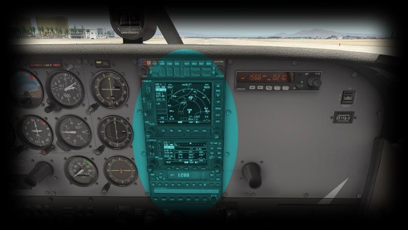
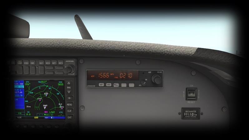
21 ADF (Automatic Direction Finder) Receiver This instrument displays a direct bearing to or from a selected NDB (Non- Directional Beacon). The frequency is selected via the ADF panel on the upperright-side of the instrument panel (described later). NDBs are simple radio transmitters. As such, the ADF instrument can also provide bearing information to non-aviation related transmitters, such as commercial radio stations, or any other radio source operating within the appropriate bandwidth. 21
,")
 receivers.")
22 Avionics Audio Switching Panel This panel is used to enable or disable audio from the selected radio and navigation devices. Audio will be in the form of speech from ATC communications (COM1, COM2, etc.), or Morse from Navigation aids (NAV1, NAV2, etc.). Each navigation aid (VOR, NDB, ILS, MKR (marker) has a Morse code identifier, to confirm the frequency selection is correct. GNS 530 The GNS 530 is Laminar Research s interpretation of the Garmin 530 series of GPS (Global Positioning System) receivers. This unit provides the pilot with the ability to input a pre-determined flight plan, which is then presented in plan view on the display. The pilot may elect to follow the course either manually, or using the autopilot. Instructions for operating the Laminar Research GPS units can be found in separate (dedicated) manuals 22

 manuals.")

23 GNS 430 The GNS 430 is Laminar Research s interpretation of the Garmin 430 series of GPS (Global Positioning System) receivers. This unit provides the pilot with the ability to input a pre-determined flight plan, which is then presented in plan view on the display. The pilot may elect to follow the course either manually, or using the autopilot. Instructions for operating the Laminar Research GPS units can be found in separate (dedicated) manuals. Transponder Panel The transponder works in conjunction with ATC radar, to identify the aircraft to controllers. When operating in controlled airspace, each aircraft is provided with a unique transponder code to accomplish this. Use the push-buttons to set the transponder code. Set the transponder to STBY when setting and operating on the ground, and ON, or ALT, when airborne. ALT mode reports both location and altitude. The IDENT button highlights your location to the controller, and should only be used when instructed. Autopilot Panel Autopilot features, and operation, are described later in this guide. 23
.")
24 Automatic Direction Finder (ADF) Panel The Automatic Direction Finder (ADF) is a radio receiver that can be tuned to any Non-Directional Beacon (NDB) that is within range. It provides a direct course to or from the radio source, which is displayed by the needle on the ADF instrument (see Secondary Instruments). NAV / GPS Button This button provides a convenient way to toggle the GPS 530 unit between VLOC (Nav) mode and GPS mode. Select VLOC (Nav) Mode to use radio navigation aids, such as VORs and ILS approaches. Select GPS Mode when navigating according to a flight plan that has been programmed into the G


25 Switch Panel Magneto-Select, and Starter This key (operated like a rotary control) selects the operational magnetos (left, right or both) and engages the starter-motor. A magneto is an electrical generator that supplies power to the spark-plugs. Two magnetos are provided for redundancy, and these are both used during normal operations. Master Alternator and Battery Switch These switches are usually operated together. The Alternator provides power to the electrical systems when the engine is running, and charges the battery. The Battery provides power to the electrical systems when the engine is not running. 25
26 Fuel Pump Toggle Switches Activates the electric fuel pump, for priming the engine before starting. This also provides a substitute for the mechanical pump in the event of a failure. Rotating Beacon Landing Light Taxi Light Navigation Lights (wings and tail) Strobe Lights (wing) Pitot-tube heater (for icing conditions) These switches actuate the electrical buses that power the avionics. Avionics Bus Switches BUS1 powers: - Comm Panel - G530 GPS - Transponder - Autopilot - VOR1 / ILS - BUS2 BUS2 powers: - G430 GPS - VOR2 - ADF - VOR2 Panel and Radio Brightness Controls The Panel Light (outer) Rotary adjust the brightness of the avionics and switch backlighting. The Radio Light (inner) Rotary adjusts the brightness of the avionics panel displays Pedestal and Glare-Shield Brightness Controls The Pedestal Light (outer) Rotary adjust the brightness of the pedestal illumination. The Glare-Shield Light (inner) Rotary adjusts the brightness of the recessed lighting below the glareshield. 26

27 Throttle & Mixture / Pedestal Throttle Lever The C172 is equipped with a single throttle that controls the engine power, and the propeller RPM. When in flight, increase the throttle to initiate a climb, and decrease the throttle to initiate a descent. Mixture Lever The C172 is equipped with a single mixture control that alters the ratio of fuel and air entering the engine. Pull backwards to lean the mixture. Push forwards to richen the mixture. As altitude increases, the pilot leans the mixture to compensate for the decrease in air-density. Mixture also affects the engine temperature, and fuel consumption. See also the EGT / Fuel flow gauge in Secondary Instruments). 27

28 Elevator Trim The Elevator Trim can be adjusted using the mouse-wheel (or mapped to a peripheral device). Elevator trim alleviates the need for the pilot to maintain backward, or forward pressure on the yoke. Trim is also used to set the desired airspeed in this aircraft. Trim up for reduced airspeed, and down for increased airspeed. Fuel Selector Used to select the desired fuel tank(s) supplying fuel to the engine. Options are: - Both (tanks) - Right (tank) - Left (tank) Normal operating procedure is to utilize both tanks simultaneously. However, there may be a need to select a single tank, in the event there is an uneven weight distribution of fuel between the two tanks, or when fueling the aircraft on uneven ground. 28

29 Annunciator Panel This panel features a group of lights that indicate the status of the aircraft s equipment or systems. Red indicators are warnings, and amber indicators are cautions. A test switch is located immediately to the right of the annunciator panel. Depressing this switch illuminates every light in the panel, to confirm each one is working prior to the flight. Severity: Caution 1 L FUEL R Left / Right Fuel Pressure: Indicates a drop in fuel pressure from either the left, or right fuel supply. This usually occurs in the event of fuel starvation, a fuel leak, or the failure of a fuel pump. 2 OIL PRESS Severity: Warning Oil Pressure: Engine oil pressure is low. This occurs when there is insufficient oil present, or in the event of an oil-pump failure. Severity: Caution 3 L VAC R Left / Right Vacuum system pressure is low. Indicates a drop in vacuum pressure from the left or right vacuum pump. This may occur at low engine RPM, or when there is a legitimate failure of the vacuum system. In the event of a failure, the following instruments will be affected: - Airspeed Indicator - Altimeter - Vertical Speed Indicator - Attitude Indicator - Heading Indicator - Turn Coordinator 4 VOLTS Severity: Warning Low Voltage: Indicates the alternator is not generating enough voltage to keep the battery charged. This may indicate an alternator failure. The battery will gradually deplete, leading to an electrical system failure. 29


30 Autopilot Operation Autopilot On/Off 1 AP This is a toggle button, used to engage and dis-engage the autopilot system respectively. When the autopilot is initially engaged, the pilot still has full manual control of the aircraft, because no autopilot mode has yet been selected. Heading Mode 2 HDG This is a toggle button, used to engage and dis-engage HEADING mode respectively. When this mode is engaged, the autopilot will turn the aircraft to the heading selected by the pilot. The pilot may select the desired heading using the Heading Bug which is a feature of the Heading Indicator (Directional Gyro). See Primary Instruments. Navigation Mode 3 NAV If the Garmin G530 is currently in GPS mode, selecting this autopilot mode will direct the aircraft laterally, according to any flight plan currently programmed into the GPS. If the Garmin G530 is in VLOC (VOR/Localizer) mode, selecting this autopilot mode will direct the aircraft to fly to, or from, the chosen radio navigation aid. 30
31 4 APR Approach Mode This mode is engaged to fly an ILS approach. NAV mode will also engage by default. The autopilot will capture the localizer and glideslope associated with the chosen ILS frequency, provided the G530 is in VLOC mode. When the aircraft captures the glideslope, and begins descending, the pilot is responsible for managing the airspeed (using the throttle). Note: The autopilot may not capture the ILS if extreme maneuvers are required to accomplish this. The pilot should therefore position the aircraft close to the localizer and glideslope, and in stable flight, before engaging APR mode. 5 REV Reverse Mode Use this mode when flying an ILS-localizer back-course. The principle is otherwise the same as APR (Approach) Mode. 6 ALT Altitude Mode Select this mode to hold the current altitude. This may also be accomplished using VS mode (where VS is set to 00 ). Vertical Speed Mode 7 VS Select this mode to maintain a desired vertical speed (when climbing or descending). Use the rotary control to set the desired rate (in units of 100 feet per minute). For example, if you wish to descend at a rate of 500 feet per minute, use the rotary control to select -05. Caution is required when using this mode, to maintain a safe airspeed. The selected rate of climb/descent may exceed the performance capability of the aircraft, resulting in airspeed that is too low, or too high. The pilot must manage this manually. 31
32 Flight Planning Flight planning is the process of determining a route from origin to destination that considers fuel requirements, terrain avoidance, Air Traffic Control, aircraft performance, airspace restrictions and notices to airmen (NOTAMS). General information about flight plans is available on Wikipedia at Flight plans can be generated by onboard computers if the aircraft is suitably equipped. If not, simulation pilots may elect to use an online flight planner. A web search for the phrase Flight Planner will yield a great many options, many of which are free services. A good online flight planner will utilize the origin and destination airports, together with the aircraft type and equipment, the weather conditions, the chosen cruise altitude, known restrictions along the route, current NOTAMS, and other factors to generate a suitable flight plan. The waypoints incorporated into the flight plan can be subsequently input into the aircraft s Flight Management Computer (FMS), or Global Positioning System (GPS). Some online flight planners provide the option to save the plan as an X-Plane compatible file, with an fms extension. A saved flight plan can be loaded into the GPS or Flight Management Computer unit featured in the C172. It is recommended the pilot generate a flight plan for the chosen route before using the GPS units. Instructions for operating the Laminar Research GPS units can be found in separate (dedicated) manuals. 32
33 Fuel Calculation Note: All calculations here are based on the X-Plane C172, and NOT the real-life C172. Differences may exist. Taxi Fuel The estimated fuel required to taxi from the startup location to the active runway at the origin, plus the estimated fuel required to taxi from the active runway to the shutdown location at the destination. This is dependent on the ground route that will be followed, and the traffic at the airports in question. The pilot must use his or her judgement to determine the total taxi time. Once this has been estimated, use the following lookup table to determine the amount of fuel required. Taxi Fuel Table Taxi Time (minutes) Fuel Flow (lbs. / hour) Total Fuel Weight (lbs.) Trip Fuel The estimated fuel required to complete the cruise portion of the trip. This will be a factor of the expected elapsed time for the flight, which will be provided by your chosen online flight planner. Once this has been calculated, use the following lookup table to determine the amount of fuel required. Trip Fuel Table Flight Time (minutes) Fuel Flow (lbs. / hour) Total Fuel Weight (lbs.)
34 Weight & Balance Proper weight and balance control is crucial to the safe operation of any aircraft. Two elements are vital in this process: Total Weight This must be no greater than the maximum allowed by the regulatory body that oversees the operation of the aircraft. In the United States, this is the Federal Aviation Administration (FAA). Center of Gravity (CG) The point at which all weight is concentrated. This must be within the allowable range published for the aircraft in question. Weight and Balance Table After calculating your fuel requirements (see Fuel Calculation), use the following table to determine the Payload Weight and Center of Gravity (CG) for your flight. This assumes an average weight of 150 lbs. per person, and a baggage weight of 50 lbs. Total Fuel Weight (lbs.) Front Seat Occupants Rear Seat Occupants Bags Payload Weight (lbs.) Gross Weight X-Plane CG Y Y Y Y Y Y Y Y Y
35 Total Fuel Weight (lbs.) Front Seat Occupants Rear Seat Occupants Bags Payload Weight (lbs.) Gross Weight X-Plane CG 80 2 Y Y Y Y Y Y Y Y Y Y Y Y Y Y Y Y Y Y Y
36 Total Fuel Weight (lbs.) Front Seat Occupants Rear Seat Occupants Bags Payload Weight (lbs.) Gross Weight X-Plane CG Y Y Y Y Y Y Y Y Y Y Y Y Y Y Y Y Y Y
37 Total Fuel Weight (lbs.) Front Seat Occupants Rear Seat Occupants Bags Payload Weight (lbs.) Gross Weight X-Plane CG Y Y Y Y Y Y Y Y Y Y Y Y Y Y Y Y Y Y Y
38 Total Fuel Weight (lbs.) Front Seat Occupants Rear Seat Occupants Bags Payload Weight (lbs.) Gross Weight X-Plane CG Y Y Y Y Y Y Y Y Y Y Y

39 Configuring the Weight and Balance in X-Plane After calculating your fuel requirements (see Fuel Calculation), and referencing the Weight and Balance Table, you are ready to configure the weight, balance and fuel for your upcoming flight. Select the Cessna 172 aircraft from the flight menu, and click on the Customize button, followed by the Weight, Balance & Fuel button. Now input the Center of Gravity, Payload Weight, Fuel Weight (Fuel Tank 1) and Fuel Weight (Fuel Tank 2). The example below is for the scenario highlighted in blue in the Weight and Balance Table. 39
40 Checklists The following check lists are designed with the convenience of the simulation pilot in mind, and customized to the X-Plane C172 aircraft. These differ from those of the real aircraft. Initial Cockpit Check Parking Brake ON Master Switch ON Battery Voltage CHECK 24+ Landing Lights ON Taxi Lights ON Navigation Lights ON Beacon ON Strobes ON Flaps Extended 40


41 Pre-Flight Exterior Inspection A Pre-Flight Inspection should always precede flight in any aircraft. The purpose of this inspection is to ensure the aircraft is in a state of readiness for the upcoming flight. In X-Plane, a pre-flight inspection is not merely undertaken to simulate reality, but does in fact have real purpose, because the control surfaces of the aircraft interact directly with the airflow over and around them, just as in real life. As such, correct movement of all control surfaces is necessary for normal flight. Hold roll axis at full deflection. Visually check corresponding movement of ailerons. Hold pitch axis at full deflection. Visually check corresponding movement of elevators. 41


42 Hold yaw axis at full deflection. Visually check corresponding movement of rudder. Visually check flaps are extended. 42

43 Visually check: 1. Beacon 2. Nav Lights 3. Strobes 4. Taxi Lights 5. Landing Lights Before Starting Engines Exterior Inspection COMPLETED Fuel Selector BOTH Parking Brake ON Lights OFF Fuel Quantity CHECK Power - IDLE Mixture Rich (Full Forward) Avionics Bus 1 & Bus 2 CHECK OFF 43
44 Engine Start Throttle - OPEN ¼ TO ½ Master Switch - ON Fuel Pump - ON Mixture RICH (until stable fuel flow indication), then LEAN Beacon ON Propeller Area CLEAR Ignition Switch START Mixture RICH (advance when engine starts) Ignition Switch BOTH Oil Pressure CHECK Avionics Bus 1 & Bus 2 ON Radios ON AND SET Transponder ON Before Taxi Flaps RETRACTED. Brakes CHECK Gyro Instruments & Compass CHECK & SET 44
45 Before Takeoff Parking Brake SET Doors and Windows - CLOSED Flight Controls - FREE & CORRECT Flight Instruments CHECK Altimeter SET Fuel Selector Valve BOTH Mixture RICH Elevator/Rudder Trim TAKEOFF Throttle RPM Magnetos CHECK Engine Instruments CHECK Ammeter CHECK Vacuum Pressure CHECK Throttle IDLE Radios AS REQUIRED Lights AS REQUIRED Transponder ALT Parking Brake RELEASE Takeoff Flaps RETRACTED Throttle - FULL OPEN Elevator - ROTATE AT 55 KIAS 45
46 Short-Field Takeoff Flaps - 10 Brakes APPLY Throttle - FULL OPEN Mixture SET for Max RPM Brakes RELEASE Elevator Control SLIGHT NOSE- HIGH until ROTATE at 55 KIAS Climb Speed - Vx to clear obstacles, then Vy Flaps RETRACTED Climb Airspeed Vy Throttle - FULL OPEN Mixture SET for Max RPM 46
47 Cruise RPM 2100 to 2700 Elevator Trim - ADJUST for desired Airspeed Mixture LEAN AS REQUIRED Descent Fuel Selector Valve BOTH Mixture RICHEN Power - AS REQUIRED 47

48 Before Landing Fuel Selector Valve BOTH Mixture RICH Flaps EXTENDED After Landing Flaps RETRACTED Strobe Lights OFF Trim - RESET 48
 OFF Mixture - IDLE CUTOFF Ignition Switch OFF Master Switch OFF Fuel Selector Valve - RIGHT TANK Hobbs and Tach Times -")
49 Engine Shutdown & Securing Aircraft Parking Brake - SET Throttle to 1000 RPM Avionics OFF Electrical Switches (except beacon) OFF Mixture - IDLE CUTOFF Ignition Switch OFF Master Switch OFF Fuel Selector Valve - RIGHT TANK Hobbs and Tach Times - RECORD 49
50 Operational Speeds Stall speeds, Flaps down, Power Off Vso 40 KIAS Stall Speed, Flaps Up, Power Off Vsi/Vs1 48 KIAS Best Angle of Climb Vx 62 KIAS Best Climb Speed Vy 74 KIAS Takeoff (rotate) Speed Vr 55 KIAS Best Glide Speed Vg 68 KIAS Maximum flaps Extended Speed - (10/30 degree) Vfe 110/85 KIAS Maneuvering Speed Va 99 KIAS Maximum Structural Speed Vno 129 KIAS Never Exceed Speed Vne 163 KIAS Enroute Climb Speed Maximum Demonstrated Crosswind Maximum Glide Speed Precautionary Landing with Engine Power Landing without Engine Power KIAS 15 KIAS 68 KIAS 65 KIAS Flaps Up -70 KIAS Flaps Down -65 KIAS 50
X-Plane 11 King Air C90B
 Pilot s Operating Manual Author: Julian Lockwood (julian@x-plane.com) Copyright: Laminar Research 2017 X-Plane 11 King Air C90B Disclaimer The information contained in this document is for simulation use
Cessna 172P PPL Checklist Page 1
 Cessna 172P PPL Checklist 06-08-2017 Page 1 Cessna 172P PPL Checklist 06-08-2017 Page 2 Checklist Items Informational Items Critical Memory Items PREFLIGHT COCKPIT CHECK (DO-LIST) Pitot Cover -- REMOVE
FIRST FLYING TECHNIQUES COCKPIT PREPARATION STARTUP TAXI
 1. Introduction FIRST FLYING TECHNIQUES COCKPIT PREPARATION STARTUP TAXI We aim to teach and demonstrate how to operate a general aviation aircraft and show some basic techniques and manoeuvres that every
Expanded Flight Checklist Cessna 152
 OUTSIDE CHECK INSIDE CABIN 1 Magnetos... OFF 2 Mixture... IDLE CUT OFF 3 Master switch... ON 4 Fuel quantity... CHECKED 5 Master switch... OFF OUTSIDE CABIN 1 Left wing... CHECKED Surface condition Flap
Cessna 172 Skyhawk. Aircraft Checklist Models: R & S
 Cessna 172 Skyhawk Aircraft Checklist Models: R & S This is an abbreviated checklist. Most explanatory items, notes cautions and warnings have been omitted for brevity. Procedures in red/bold text in this
Cirrus SR20 Microsoft Flightsimulator 2002
 Cirrus SR20 Microsoft Flightsimulator 2002 Aircraft and Panel : Günter Kraemer Werner Schott Günter Kraemer Switzerland Germany w.schott@abbts.ch guenter@kraemerg.de Page 12 Page 1 Other simulator checklists
Cessna 172S Skyhawk. AFTER LANDING CHECK RPM CHECK 2. Flaps UP 3. Transponder STANDBY 4. Strobes OFF 5. Contact Ground as Required. 121.
 PRE-LANDING CHECK 1. ATIS/AWOS/ASOS OBTAIN 2. Seat Belts CHECK 3. Autopilot OFF 4. Master Switch ON 5. Ignition BOTH 6. Circuit Breakers ALL IN 7. Landing Light AS REQ. 8. Mixture (Push) RICH 9. Fuel Selector
Cessna 172RG WARNING. Maximum Demonstrated Crosswind. Takeoff or landing..15 KTS
 Cessna 172RG INTRODUCTION: This aircraft checklist contains information from the original manufacturer s Pilot Information Manual. Normal procedures associated with optional systems can be found in Section
2. What type and size (hp) engine does the airplane have? Lycoming O540-JC35D rated at 235 BHP at 2400 RPM
 engine does the airplane have? Lycoming O540-JC35D rated at 235 BHP at 2400 RPM") This quiz will help test your knowledge of the POH and the systems and equipment in CR-182 N133BW. In preparation for your checkout flight, answer all of the following questions as thoroughly as possible
This quiz will help test your knowledge of the POH and the systems and equipment in CR-182 N133BW. In preparation for your checkout flight, answer all of the following questions as thoroughly as possible
PREFLIGHT. Cessna 152 Checklist. Review Aircraft Maintenance Status Sheet Parking Brake. Certificates, POH, & Wt & Bal Check
 Cessna 152 list PREFLIGHT CABIN Review Aircraft Maintenance Status Sheet Parking Brake Control Lock Remove Certificates, POH, & Wt & Bal Avionics All E.L.T. Battery Switch Fuel Indicators Down All Switches
Best Glide 75 kias (Max Gross)
") CESSNA 172XP CHECKLIST PREFLIGHT (Interior) 1. ACFT DOCS / INSPECTIONS--------CHECK 2. TACH TIME-----------------------------RECORD 3. CONTROL LOCK---------------------REMOVE 4. ELEVATOR / RUDDER TRIM------------
CESSNA 172XP CHECKLIST PREFLIGHT (Interior) 1. ACFT DOCS / INSPECTIONS--------CHECK 2. TACH TIME-----------------------------RECORD 3. CONTROL LOCK---------------------REMOVE 4. ELEVATOR / RUDDER TRIM------------
I. DISPATCH PLANNING & AIRCRAFT EXTERIOR CHECK
 SCHODACK AVIATION Page 1 of 10 I. DISPATCH PLANNING & AIRCRAFT EXTERIOR CHECK 1. Flight Planning 1. Aircraft requirements & preparation: Required aircraft documents: Airworthiness Certificate Registration
I. DISPATCH PLANNING & AIRCRAFT EXTERIOR CHECK
 SCHODACK AVIATION Page 1 of 10 I. DISPATCH PLANNING & AIRCRAFT EXTERIOR CHECK 1. Flight Planning 1. Aircraft requirements & preparation: 1. Required aircraft documents: 1. Airworthiness Certificate 2.
PREFLIGHT CHECK COCKPIT RIGHT WING. NORMAL PROCEDURRES CHECKLIST PA-28RT 201 Arrow IV
 NORMAL PROCEDURRES CHECKLIST PA-28RT 201 Arrow IV PREFLIGHT CHECK COCKPIT Control Wheel -- Release Restraints Avionics -- OFF Parking Brake -- SET All Switches -- OFF Mixture -- IDLE CUT-OFF Master Switch
N955DK RV-8A David B. Kumhyr. N955DK Version 05Nov04 RV-8A
 N955DK RV-8A David B. Kumhyr Operating Speeds Reference VREF Flight Regime Kts Mph Vso Stall, dirty (gross)... Stall, dirty (solo).. 50 58 Vs.. Stall, clean (gross)... Stall, clean (solo). 55 63 Vr.. Rotation.
Van s Aircraft RV-7A. Pilot s Operating Handbook N585RV
 Van s Aircraft RV-7A Pilot s Operating Handbook N585RV PERFORMANCE SPECIFICATIONS SPAN:..25 0 LENGTH...20 4 HEIGHT:.. 7 10 SPEED: Maximum at Sea Level...180 knots Cruise, 75% Power at 8,000 Ft...170 knots
X-Plane 11 MD-82. Pilot s Operating Manual. Disclaimer. Distribution. Author: Julian Lockwood Copyright: Laminar Research 2018
 Pilot s Operating Manual Author: Julian Lockwood (julian@x-plane.com) Copyright: Laminar Research 2018 X-Plane 11 MD-82 Disclaimer The information contained in this document is for simulation use only,
CESSNA SECTION 4. Unless otherwise noted, the following speeds are based on a maximum weight of 2550 pounds and may be used for any lesser weight.
 CESSNA SECTION 4 INTRODUCTION Section 4 provides procedures and amplified instructions for normal operations using standard equipment. Normal procedures associated with optional systems can be found in
HU-16 Albatross USER MANUAL. Virtavia HU-16 Albatross DTG Steam Edition Manual Version 1.0
 HU-16 Albatross USER MANUAL 0 Introduction The Grumman HU-16 Albatross is a twin-engine amphibious flying boat. First flown in 1949, the HU-16 underwent a number of modifications and improvements over
CESSNA 172S NAV III VFR CHECKOUT POH EXAMINATION (Based on N1129K, serial no. 172S revised 10/05/06)
") INTRODUCTION, POH CESSNA 172S NAV III VFR CHECKOUT POH EXAMINATION (Based on N1129K, serial no. 172S10315 - revised 10/05/06) 1. Rate of climb at sea level: 2. Service ceiling: 3. Takeoff performance,
INTRODUCTION, POH CESSNA 172S NAV III VFR CHECKOUT POH EXAMINATION (Based on N1129K, serial no. 172S10315 - revised 10/05/06) 1. Rate of climb at sea level: 2. Service ceiling: 3. Takeoff performance,
Vso 61. Vs1 63. Vr 70. Vx 76. Vxse 78. Vy 89. Vyse. 89 (blue line) Vmc. 61 (radial redline) Vsse 76. Va 134) Vno 163
 Vmc. 61 (radial redline) Vsse 76. Va 134) Vno 163") PA34-200T Piper Seneca II Normal procedures V-speeds Knots Vso 6 Vs 63 Vr 70 Vx 76 Vxse 78 Vy 89 Vyse Vmc 89 (blue line) 6 (radial redline) Vsse 76 Va 2-36(@4507lbs 34) Vno 63 Vfe 38 (0*)/2(25*)/07(40*)
PA34-200T Piper Seneca II Normal procedures V-speeds Knots Vso 6 Vs 63 Vr 70 Vx 76 Vxse 78 Vy 89 Vyse Vmc 89 (blue line) 6 (radial redline) Vsse 76 Va 2-36(@4507lbs 34) Vno 63 Vfe 38 (0*)/2(25*)/07(40*)
The engines are designed to use 100/130 octane fuel. If not available use next higher grade. - 1
 PNEUMATIC SYSTEM The aircraft has a dual pneumatic system. In case of failure of either pneumatic pump, the system will automatically select the operative source. (Inoperative source will be indicated
X-Plane 11 Boeing
 Pilot s Operating Manual Author: Julian Lockwood (julian@x-plane.com) Copyright: Laminar Research 2018 X-Plane 11 Boeing 737-800 Disclaimer The information contained in this document is for simulation
NORMAL PROCEDURRES CHECKLIST PA T SENECA II PREFLIGHT CHECK INSIDE CABIN OUTSIDE CABIN
 NORMAL PROCEDURRES CHECKLIST PA-34-200T SENECA II PREFLIGHT CHECK INSIDE CABIN Avionics Master Switch -- OFF Landing Gear Control. -- DOWN Mixture Controls -- IDLE/CUTOFF Ignition Switches -- OFF Master
V - Speeds. RV-10 V fe Flaps Speeds Trail (0 deg) Half (15 deg) Full (30 deg) 122 kias 96 kias. 80 kias
 Half (15 deg) Full (30 deg) 122 kias 96 kias. 80 kias") RV-10 Check List V - Speeds RV-10 V fe Flaps Speeds Trail (0 deg) Half (15 deg) Full (30 deg) 122 kias 96 kias 87 kias V s1 Stall (Flap Up) 60 kias V s0 Stall (Flap 40 deg) 55 kias Best Glide 80 kias V
RV-10 Check List V - Speeds RV-10 V fe Flaps Speeds Trail (0 deg) Half (15 deg) Full (30 deg) 122 kias 96 kias 87 kias V s1 Stall (Flap Up) 60 kias V s0 Stall (Flap 40 deg) 55 kias Best Glide 80 kias V
CESSNA 182 CHECKLIST. LEFT WING Trailing Edge 1. Aileron CHECK freedom of movement and security
 CESSNA 182 CHECKLIST PRE-FLIGHT INSPECTION CABIN 1. Pilot s Operating Handbook AVAILABLE IN THE AIRPLANE (A.R.R.O.W.E) 2. Landing Gear Lever DOWN 3. Control Wheel Lock REMOVE 4. Ignition Switch OFF 5.
Aircraft Checklist Cessna 182T
 Aircraft Checklist Cessna 182T This is an abbreviated checklist. Most explanatory items, notes cautions and warnings have been omitted for brevity. Procedures in red/bold in this checklist should be committed
S A F E T Y NORMAL PROCEDURES NORMAL PROCEDURES BEFORE STARTING ENGINE PASSENGER SAFETY BRIEFING STARTING ENGINE
 PRE-FLIGHT PRE-FLIGHT BEFORE STARTING ENGINE PASSENGER SAFETY BRIEFING 1. Preflight Inspection COMPLETE 2. Passenger Safety Briefing COMPLETE 3. Seats, Belts, Shoulder Harnesses ADJUST AND LOCK 4. Fuel
N1523J CHECKLIST PA Nebraska Flight Center Eppley Airfield 3737 Orville Plaza Omaha, NE Tel. (402)
") CHECKLIST N1523J 1967 Cherokee 140 PA-28-140 F Nebraska Flight Center Eppley Airfield 3737 Orville Plaza Omaha, NE 68110 Tel. (402) 342-4314 www.nebflight.com Piper Cherokee 140 N1523J 1967 GENERAL INFORMATION
CHECKLIST N1523J 1967 Cherokee 140 PA-28-140 F Nebraska Flight Center Eppley Airfield 3737 Orville Plaza Omaha, NE 68110 Tel. (402) 342-4314 www.nebflight.com Piper Cherokee 140 N1523J 1967 GENERAL INFORMATION
Interior Pre Flight Documents: Check Control Wheel Lock: Remove Flight Controls: Check Instruments: Check for Damage Switches: Verify All Off Master
 Interior Pre Flight Documents: Check Control Wheel Lock: Remove Flight Controls: Check Instruments: Check for Damage Switches: Verify All Off Master Switch ALT/BAT: On Fuel Gauge: Check Quantity Flaps:
Piper Archer II (PA )
") 1. Oil... 6-8 qts, Cap Secure CABIN 1. POH & Documents.. Check Available 2. Magneto Switch...... OFF 3. Pitot/Static Drains... Push to Drain 4. Avionics/Electrical Switches... OFF 5. Master Switch. ON
1. Oil... 6-8 qts, Cap Secure CABIN 1. POH & Documents.. Check Available 2. Magneto Switch...... OFF 3. Pitot/Static Drains... Push to Drain 4. Avionics/Electrical Switches... OFF 5. Master Switch. ON
NORMAL PROCEDURES CHECKLIST - DA20-C1 NORMAL PROCEDURES CHECKLIST - DA20-C1 RISK MANAGEMENT PREFLIGHT INSPECTION
 RISK MANAGEMENT Pilot Aircraft environment External Recent Experience Recent Skill Level Illness Medication Stress Alcohol Fatigue Eating Airworthiness (AROW) Equipment Status Engine Performance, Takeoff
NORMAL CHECKLIST ATTENTION!
 Avion Training CHECKLIST Normal Checklist CESSNA 172R / TC-STS Cessna 172 R TC-STS NORMAL CHECKLIST ATTENTION! DO NOT STOW THIS CHECKLIST IN DIRECT SUNLIGHT Avion Training - Doc.nr. 212 Revision 1 / 02022018
CESSNA 182 TRAINING MANUAL. Trim Control Connections
 Trim Control Connections by D. Bruckert & O. Roud 2006 Page 36 Flaps The flaps are constructed basically the same as the ailerons with the exception of the balance weights and the addition of a formed
Elmendorf Aero Club Aircraft Test
 DO NOT WRITE ON THIS TEST FEB 2013 Elmendorf Aero Club Aircraft Test Cessna - 172 For the following questions, you will need to refer to the Pilots Information Manual for the C-172R (180hp). The bonus
Flight Checklist for Normal Operations Massgebend ist das AFM (Parameters, Restrictions, Emergency, etc.)
") Flight Checklist for Normal Operations Massgebend ist das AFM (Parameters, Restrictions, Emergency, etc.) Jan18 1 COCKPIT PREPARATION BEFORE STARTING ENGINE 1 Aircraft + Cockpit Inspection COMPLETED 1
Flight Checklist for Normal Operations Massgebend ist das AFM (Parameters, Restrictions, Emergency, etc.) Jan18 1 COCKPIT PREPARATION BEFORE STARTING ENGINE 1 Aircraft + Cockpit Inspection COMPLETED 1
Cessna 152 Checklist
 Cessna 152 Checklist This checklist covers the operation of the model 152. Use at your own risk, the author nor the publisher is responsible for any damage or accidents resulting from the use of this checklist.
Flight checklist for normal operations Massgebend ist das AFM (parameters, restrictions, emergency, etc.)
") JAN13 1 Flight checklist for normal operations Massgebend ist das AFM (parameters, restrictions, emergency, etc.) Cockpit preparation before starting engine 1 Aircraft + Cockpit inspection completed (according
JAN13 1 Flight checklist for normal operations Massgebend ist das AFM (parameters, restrictions, emergency, etc.) Cockpit preparation before starting engine 1 Aircraft + Cockpit inspection completed (according
The Straight Word. Cessna 337 Skymaster 337C Series. The front engine should always be started first as the battery-to-starter cable is shorter.
 The Straight Word Cessna 337 Skymaster 337C Series I. FLIGHT PROCEDURES: COCKPIT PREPARATION Heading Bug OBS Indicator Altimeters Trims Parking Brake Set QFU Set Course Set QNH Set for Takeoff Apply ENGINE
CHECKLIST 1969 CESSNA 172-K. NOTE: Verify all information with airplane's POH
 CHECKLIST 1969 CESSNA 172-K NOTE: Verify all information with airplane's POH PRE-FLIGHT INSPECTION 1 CABIN 1 A.R.R.O.W. CHECK Airworthiness Cert. In Clear View Registration In Clear View Radio License
Elmendorf Aero Club Aircraft Test
 DO NOT WRITE ON THIS TEST FEB 2013 Elmendorf Aero Club Aircraft Test Cessna - 182 For the following questions, you will need to refer to the Pilots Information Manual for the C-182R. The bonus questions
NORMAL PROCEDURES CHECKLIST - C 172M PREFLIGHT INSPECTION RISK MANAGEMENT
 RISK MANAGEMENT Pilot Aircraft environment External Recent Experience Recent Skill Level Illness Medication Stress Alcohol Fatigue Eating Airworthiness (AROW) Equipment Status Engine Performance, Takeoff
Com Active/Standby Frequency Switch. C om Active/Standby Frequencies. Terrain. Flight Plan. Button. Button
 ALABEO GNS530 Nav Active/Standby Frequency Switch Com Active/Standby Frequency Switch C om Active/Standby Frequencies Zoom In/Out Button Nav Active/Standby Frequencies On/Off Button Direct To Button Nav1
Checklist Robin DR40
 Flight Checklist for Normal Operations Massgebend ist das AFM (Parameters, Restrictions, Emergency, etc.) Jan 18 1 COCKPIT PREPARATION BEFORE STARTING ENGINE 1 Aircraft + Cockpit Inspection COMPLETED 1
DO NOT WRITE ON THIS TEST FEB 2013 Elmendorf Aero Club Aircraft Test. Cessna - 182
 DO NOT WRITE ON THIS TEST FEB 2013 Elmendorf Aero Club Aircraft Test Cessna - 182 For the following questions, you will need to refer to the Pilots Information Manual for the C-182R. The bonus questions
Elmendorf Aero Club Aircraft Test
 DO NOT WRITE ON THIS TEST FEB 2014 Elmendorf Aero Club Aircraft Test Cessna - 185 For the following questions, you will need to refer to the Pilots Information Manual for the C-185F and Graphic Engine
Aircraft Checklist Commander 114
 Aircraft Checklist Commander 114 This is an abbreviated checklist. Most explanatory items, notes cautions and warnings have been omitted for brevity. Procedures in red/bold text in this checklist should
DIAMOND DA40 PILOTS MANUAL
 DIAMOND DA40 PILOTS MANUAL INTRODUCTION THIS IS THE SLEEK AND FUTURISTIC DIAMOND STAR DA40 XLS BY DIAMOND AIRCRAFT CORPORATION. THE DIAMOND STAR FEATURES 4 SEATS, AND OPTIONAL EXPANDED REAR CARGO AREA,
The Straight Word. Cessna 337 Super Skymaster 337G & T337G Series, and corresponding Reims Aviation models
 The Straight Word Cessna 337 Super Skymaster 337G & T337G Series, and corresponding Reims Aviation models I. FLIGHT PROCEDURES: COCKPIT PREPARATION Heading Bug OBS Indicator Altimeters Trims Parking Brake
Checklist LN-DAG SFK 2014
 Checklist LN-DAG SFK 2014 2 GROUND Exsterior Checklist 1. Fuel (wings & filter) - Drained 2. Documents - Checked 3. Fire extinguisher, first aid sur. kit - Checked 4. Magnetos - Off 5. Master switch -
N123AX Piper Saratoga II HP (PA-32R-301) Checklist (v23 - Revision 3 April 2011) AIRSPEEDS FOR SAFE OPERATIONS. Best Rate of Climb (gear up, flaps up)
 Checklist (v23 - Revision 3 April 2011) AIRSPEEDS FOR SAFE OPERATIONS. Best Rate of Climb (gear up, flaps up)") N123AX Piper Saratoga II HP (PA-32R-301) Checklist (v23 - Revision 3 April 2011) AIRSPEEDS FOR SAFE OPERATIS Best Rate of Climb (gear down, flaps up) Best Rate of Climb (gear up, flaps up) Turbulent Air
N123AX Piper Saratoga II HP (PA-32R-301) Checklist (v23 - Revision 3 April 2011) AIRSPEEDS FOR SAFE OPERATIS Best Rate of Climb (gear down, flaps up) Best Rate of Climb (gear up, flaps up) Turbulent Air
pilots checklist C - 172
 pilots checklist C - 172 TRIP PREPARATION 1. CFPL on board 2. MAPS on board 3. KOSIF, NOTAM, meteo checked 4. passport, pilot licence, AOPA card on board 5. cash and credit cards on board 6. trip equipment
Jump to Table of Contents
 Jump to Table of Contents PIPER AIRCRAFT CORPORATION PA-28R-201, CHEROKEE ARROW III SECTION 3 EMERGENCY PROCEDURES 3.3 EMERGENCY PROCEDURES CHECK LIST ENGINE FIRE DURING
North American F-86F Sabre USER MANUAL. Virtavia F-86F Sabre DTG Steam Edition Manual Version 1
 North American F-86F Sabre USER MANUAL 0 Introduction The F-86 Sabre was a natural replacement for the F-80 Shooting Star. First introduced in 1949 for the United States Air Force, the F-86 featured excellent
3. What is the total fuel capacity with normal tanks? Usable? 4. What is the total fuel capacity with long range tanks? Usable?
 Pilot Name: Last, first, mi. Date: (mo/dy/yr) Instructor: Pass/Fail: Instructors Initials: 1. What is the engine Manufacturer: Model: Type: 2. What is the horsepower rating? 3. What is the total fuel capacity
INDEX: Normal Procedures Emergency Procedures Pre Flight Inspection NORMAL PROCEDURES BEFORE STARTING ENGINE
 INDEX: Normal Procedures Emergency Procedures Pre Flight Inspection NORMAL PROCEDURES BEFORE STARTING ENGINE 1. Preflight Inspection -- COMPLETE 2. Seats, Belts, Shoulder Harnesses -- ADJUST and LOCK 3.
CHECKLIST FOR NORMAL OPERATION PIPER P32R
 FLUGSCHULE GRENCHEN CHECKLIST Piper Saratoga SP 1 CHECKLIST FOR NORMAL OPERATION PIPER P32R Parameters, restrictions, procedures and emergency procedures see AFM BEFORE FIRST FLIGHT 1. Aircraft & Cockpit
TECNAM P2004 BRAVO N128LS
 TECNAM P2004 BRAVO N128LS GENERAL INFORMATION NORMAL PROCEDURES TIME SENSITIVE EMERGENCY TECNAM P2004 BRAVO CHECKLIST [FLIGHT PLAN DESIGNATION IS BRAV ] EMERGENCY CONTACT The following are First Landings'
RFC Dallas, Inc. AIRCRAFT QUESTIONNAIRE (9/25/2016) "A Safe Pilot Knows His Equipment"
 A Safe Pilot Knows His Equipment") RFC Dallas, Inc. AIRCRAFT QUESTIONNAIRE (9/25/2016) "A Safe Pilot Knows His Equipment" NAME: Date: Aircraft: Cessna 182Q Registration Number: N631S Serial Number: The purpose of this questionnaire is to
RFC Dallas, Inc. AIRCRAFT QUESTIONNAIRE (9/25/2016) "A Safe Pilot Knows His Equipment" NAME: Date: Aircraft: Cessna 182Q Registration Number: N631S Serial Number: The purpose of this questionnaire is to
Convair XB-46 USER MANUAL. Virtavia XB-46 Manual Version DTG 1.0
 Convair XB-46 USER MANUAL 0 Introduction For the 1944 jet bomber competition, Consolidate Vultee (which became Convair) offered their model 109, which featured four Allison J-35-C-3 jet engines slung under
Section 1: List of Configurations Currently Approved:
 Section 1: List of Configurations Currently Approved: 1. Configuration: TD2 BASIC-Standard - Single Engine, Land, Optional Fixed or Retractable Gear, Optional Fixed Pitch or Constant Speed Propeller, Optional
IN-FLIGHT CHECK LIST B-17 Technical Session for Flight Engineers 11/18/2017 (with REVISION)
") IN-FLIGHT CHECK LIST B-17 Technical Session for Flight Engineers 11/18/2017 (with REVISION) Check Lists became an integral part of aviation following the tragic loss of Boeing 299 the prototype for the
IN-FLIGHT CHECK LIST B-17 Technical Session for Flight Engineers 11/18/2017 (with REVISION) Check Lists became an integral part of aviation following the tragic loss of Boeing 299 the prototype for the
PA GURW (December 30, 2000) PRE-START. Langley Flying School. Airspeeds (MPH) for Safe Operation. Cockpit Checks
 PRE-START. Langley Flying School. Airspeeds (MPH) for Safe Operation. Cockpit Checks") Langley Flying School PA-34-200 GURW (December 30, 2000) Airspeeds (MPH) for Safe Operation V y (all weights) 105 V x (all weights) 90 En Route Climb 120 V mc 80 V yse 105 V xse 93 V r 80 V r (25 Flaps)
Langley Flying School PA-34-200 GURW (December 30, 2000) Airspeeds (MPH) for Safe Operation V y (all weights) 105 V x (all weights) 90 En Route Climb 120 V mc 80 V yse 105 V xse 93 V r 80 V r (25 Flaps)
Preflight Inspection Cabin EMPENNAGE RIGHT WING Trailing Edge RIGHT WING NOSE
 Preflight Inspection Cabin 1. Control Wheel Lock REMOVED 2. Ignition Switch OFF 3. Avionics Power Switch OFF 4. Master Switch ON 5. Fuel Quantity Indicators CHECK QUANTITY 6. Master Switch OFF 7. Fuel
PA32-RT LANCE II CHECKLIST
 PA32-RT LANCE II CHECKLIST 6815.10.1112 1 Normal Procedures PREFLIGHT CHECK Control Wheel... RELEASE BELTS Parking brake... Set Master Switch... ON Fuel Quantity Gauges... check Master Switch... OFF Ignition...
PIPER CUB J3-65 N68952 PRE-FLIGHT CHECKLIST
 PRE-FLIGHT CHECKLIST COCKPIT Check airworthiness certificate, registration, weight & balance documentation Battery - CONNECTED Plug in headsets or secure as required Fuel ON Primer CLOSED & LOCKED Carb
MULTI ENGINE FLIGHT TRAINING MANUAL PA FTM
 www.theaviatornetwork.com Multi FTM PAGE 1 2011 01-17-2011 MULTI ENGINE FLIGHT TRAINING MANUAL PA-23-160 GRYDER NETWORKS, LLC Dan Gryder, CFII, MEI, ATP, AGI DC-3 DC-9 CE-500 B-757 B-767 B-777 The Herpa
Pilot s Checklist PIPER ARROW PA-28R-201
 Pilot s Checklist PIPER ARROW PA-28R-201 Original Issue 10/31/2012 REVISIONS Changes and/or additions in this checklist will be covered by Owner Advisories published by the Piper Aircraft Corporation.
PA34-220T Piper Seneca III
 PREFLIGHT PA34-220T Piper Seneca III Weight and Balance Documents -Airworthiness Certificate -Registration -Airplane Flight Manual -Weight & Balance Hobbs/Time Landing Gear Avionics and Fan(s) Cowl Fuel
P68 Observer 2 STANDARD EQUIPMENT LIST V
 P68 Observer 2 STANDARD EQUIPMENT LIST V9.03.12 P68 OBSERVER 2 IMPORTANT NOTE: this document is a general description of the aircraft equipment only. It is not a technical document and is to be used only
CESSNA 172I CESSNA 172I PREFLIGHT INSPECTION
 PREFLIGHT INSPECTION Visually check airplane for general condition during walk-around inspection. In cold weather, remove even small accumulations of frost, ice or snow from wing, tail and control surfaces.
Cessna 182S-CHECKLIST PROCEDURES
 Cessna 182S-CHECKLIST PROCEDURES PREFLIGHT INSPECTION 1 CABIN 1. Pitot Tube Cover -- REMOVE (if installed) and check for stoppage 2. Pilot s Operating Handbook AVAILABLE IN THE AIRPLANE 3. Airplane Weight
CESSNA 172N 08E/97E CESSNA 172N 08E/97E PREFLIGHT INSPECTION
 PREFLIGHT INSPECTION Visually check airplane for general condition during walk-around inspection. In cold weather, remove even small accumulations of frost, ice or snow from wing, tail and control surfaces.
AIRCRAFT FAMILIARIZATION. Some questions may not apply to the aircraft you are flying.
 541-895-5935 Name Date AIRCRAFT FAMILIARIZATION Note: If this information is not provided in the aircraft s flight manual give it your best guess. Some questions may not apply to the aircraft you are flying.
CARENADO COPYRIGHTS. Normal & Emergency Checklist
 NORMAL PROCEDURES CHECKLIST PREFLIGHT CHECK Control wheel -- RELEASE BELTS Avionics -- OFF Master Switch -- ON Fuel quantity gauges -- CHECK Master switch -- OFF Ignition -- OFF Exterior -- CHECK FOR DAMAGE
PIPER CUB J3-65 N68952 PRE-FLIGHT CHECKLIST COCKPIT
 PIPER CUB J3-65 N68952 PRE-FLIGHT CHECKLIST COCKPIT Check airworthiness certificate, registration, weight & balance documentation Battery - CONNECTED Plug in headsets or secure as required Fuel ON Magnetos
CHAPTER 2 THE TUTOR. Introduction
 CHAPTER 2 THE TUTOR Introduction 1. AEFs. The Royal Air Force has 12 units throughout the country known as Air Experience flights (AEFs). Their role is to provide air experience flying for cadets and they
Vr V STANDARD EQUIPMENT LIST
 Vr V5.02.09 STANDARD EQUIPMENT LIST IMPORTANT NOTE: this document is a general description of the aircraft equipment only. It is not a technical document and is to be used only for the purpose of generally
OPERATIONS MANUAL FTO SECTION : 06.04
 06.04.08. OO-WIK SECTION : 06.04 PARTENAVIA OO-WIK PAGE : 1 PRE ENTRY PITOT COVER - REMOVE SNOW / ICE CHECK AIRCRAFT NOSE INTO WIND AIRCRAFT WEIGHT & BALANCE WITHIN LIMITS EXTERNAL (COCKPIT FIRST) PARK
PA28R ARROW CHECKLIST
 PA28R ARROW CHECKLIST 2300.11.0112 1 Normal Procedures Initial PREFLIGHT CHECK General Appearance... CHECKED Position & Taxi Path... CHECKED Tie Downs, Locks, Chocks & Covers... REMOVED Cockpit Controls...UNLOCKED
Systems PA28R-201 ARROW. Engine. Make : Avco Lycoming. Model: IO-360 C1C6. Type:
 1 Systems PA28R-201 ARROW Engine Make : Avco Lycoming Model: Type: IO-360 C1C6 4 cylinders Horizontally opposed Normally aspirated(no turbo charge) Air cooled (Engine oil and fuel helps cooling) Direct
The Straight Word. Cessna 208 Caravan 208 Caravan I & 208B Grand Caravan Series
 The Straight Word Cessna 208 Caravan 208 Caravan I & 208B Grand Caravan Series I. FLIGHT PROCEDURES: COCKPIT PREPARATION Fuel Tank Selectors Ignition Switch Heading Bug HSI Course Indicator Altimeters
by Greg Whiley Aussie Star Flight Simulation
 Flying the BAe 146 200/300 Version 2 by Greg Whiley Aussie Star Flight Simulation INTENTIALLY LEFT BLANK Greg Whiley Aussie Star Flight Simulation 2 Version Date Revision Version 1.0 25 June 2014 Original
Vr (P68R) STANDARD EQUIPMENT LIST V
 STANDARD EQUIPMENT LIST V") Vr (P68R) STANDARD EQUIPMENT LIST V15.04.16 IMPORTANT NOTE: this document is a general description of the aircraft equipment only. It is not a technical document and is to be used only for the purpose
Vr (P68R) STANDARD EQUIPMENT LIST V15.04.16 IMPORTANT NOTE: this document is a general description of the aircraft equipment only. It is not a technical document and is to be used only for the purpose
TECNAM P92 EAGLET N615TA TECNAM P92 EAGLET CHECKLIST [FLIGHT PLAN DESIGNATION IS ECHO ]
![TECNAM P92 EAGLET N615TA TECNAM P92 EAGLET CHECKLIST [FLIGHT PLAN DESIGNATION IS ECHO ]](/thumbs/86/93080937.jpg "TECNAM P92 EAGLET N615TA TECNAM P92 EAGLET CHECKLIST [FLIGHT PLAN DESIGNATION IS ECHO ]") TECNAM P92 EAGLET CHECKLIST [FLIGHT PLAN DESIGNATION IS ECHO ] EMERGENCY CONTACT The following are First Landings' emergency contact telephone numbers. We ask that you call the numbers in the order listed.
TECNAM P92 EAGLET CHECKLIST [FLIGHT PLAN DESIGNATION IS ECHO ] EMERGENCY CONTACT The following are First Landings' emergency contact telephone numbers. We ask that you call the numbers in the order listed.
IntelliFlight 2100 Programmer/Computer PN Software Mod Code L or Later WAAS Capable Pilot s Operating Handbook
 IntelliFlight 2100 Programmer/Computer PN 01304 Software Mod Code L or Later WAAS Capable Pilot s Operating Handbook NAV VS 500 ALT 12 5 00 List of Effective Pages * Asterisk indicates pages changed, added,
Van s Aircraft RV-4. Pilot s Operating Handbook
 Van s Aircraft RV-4 Pilot s Operating Handbook PERFORMANCE SPECIFICATIONS SPAN:.. 23 0 LENGTH:. 19 9 HEIGHT:. 6 8 SPEED: Maximum at Sea Level.. Cruise, 75% Power at 8,000 Ft.. 173 Knots 165 Knots RANGE
AIRPLANE FLIGHT MANUAL AQUILA AT01 AIRPLANE FLIGHT MANUAL - SUPPLEMENT AVE28 GLASS COCKPIT. equipped with ASPEN EFD1000 PFD
 SECTION 9 AIRPLANE FLIGHT MANUAL - SUPPLEMENT AVE28 GLASS COCKPIT equipped with ASPEN EFD1000 PFD This AFM supplement is applicable and must be inserted into Section 9 of the Airplane Flight Manual when
AIR TRACTOR, INC. OLNEY, TEXAS
 TABLE OF CONTENTS LOG OF REVISIONS... 2 DESCRIPTION... 4 SECTION 1 LIMITATIONS... 5 SECTION 2 NORMAL PROCEDURES... 8 SECTION 3 EMERGENCY PROCEDURES... 8 SECTION 4 MANUFACTURER'S SECTION - PERFORMANCE...
* Transit flight deck preparation
 Page 1 Explanations * Transit flight deck preparation Procedures By heart items FFD OUTSIDE CHECK INSIDE CABIN First flight a day 1 Crossfeed drain... DRAINED - Drain crossfeed left hand of left forward
FSFlyingSchool2010 Cessna 172 Detail Pack
 FSFlyingSchool2010 Cessna 172 Detail Pack Manual Web: www.fsflyingschool.com Support: [www.fsflyingschool.com/forum] Forum: [www.fsflyingschool.com/forum] Sales: [sales@fsflyingschool.com] Published: June
COLUMBIA 350 EMERGENCY PROCEDURES
 COLUMBIA 350 EMERGENCY PROCEDURES TABLE OF CONTENTS EMERGENCY PROCEDURES LANDING AND TAKEOFF Engine Failure During Takeoff...1 Engine Failure Immediately After Takeoff...1 Engine Failure During Climb to
INDEX. Preflight Inspection Pages 2-4. Start Up.. Page 5. Take Off. Page 6. Approach to Landing. Pages 7-8. Emergency Procedures..
 INDEX Preflight Inspection Pages 2-4 Start Up.. Page 5 Take Off. Page 6 Approach to Landing. Pages 7-8 Emergency Procedures.. Page 9 Engine Failure Pages 10-13 Propeller Governor Failure Page 14 Fire.
Liberty Aerospace, Inc. Section 1 SECTION 1 GENERAL TABLE OF CONTENTS
 Liberty Aerospace, Inc. Section 1 SECTION 1 TABLE OF CONTENTS Introduction... 1-3 Airplane Three Views... 1-4 Descriptive Data... 1-5 Engine... 1-5 Propeller... 1-5 Fuel... 1-5 Oil... 1-5 Maximum Certificated
Tie down IAS-TAS Table 14
 PA28-161- 1 Piper PA28-161 Archer II Cockpit Interior Exterior Check Exterior Check [cont.] Before Start Engine Start After Start ENG Flooded Start Start with External Pwr Run-Up Before Takeoff Short Field
Flight Procedures Aero AT-3 R100
 Flight Procedures Page: 1 1. FOREWORD... 3 2. FLIGHT PREPARATION... 3 3. PRE-FLIGHT CHECK... 3 3.1. External inspection:... 4 3.2. In the cockpit... 4 3.3. Left wing... 5 3.4. Engine nacelle, canopy and
SECTION IV NORMAL PROCEDURES TABLE OF CONTENTS
 SECTION IV NORMAL PROCEDURES TABLE OF CONTENTS SUBJECT PAGE Speeds for Safe Operation 4-3 Preflight Inspection 4-4 Before Starting 4-5 External Power 4-6 Starting Engine Using Auxiliary Power Unit. 4-7
JODEL D.112 INFORMATION MANUAL C-FVOF
 JODEL D.112 INFORMATION MANUAL C-FVOF Table of Contents I General Description...4 Dimensions:...4 Powertrain:...4 Landing gear:...4 Control travel:...4 II Limitations...5 Speed limits:...5 Airpeed indicator
Wings of Carolina Flying Club PA Aircraft Type Checkout and Currency Quiz
 Wings of Carolina Flying Club PA-28-161 Aircraft Type Checkout and Currency Quiz Pilot Instructor Score Date Instructor: Please note the final score (subtract 2.5 points from 100 for each wrong answer)
XIV.C. Flight Principles Engine Inoperative
 XIV.C. Flight Principles Engine Inoperative References: FAA-H-8083-3; POH/AFM Objectives The student should develop knowledge of the elements related to single engine operation. Key Elements Elements Schedule