E-2C Hawkeye USER MANUAL. Virtavia E-2C Hawkeye Manual Version 1.0
|
|
|
- Aron Ward
- 6 years ago
- Views:
Transcription

1 E-2C Hawkeye USER MANUAL 0
2 Introduction The E-2C is an all-weather twin turboprop carrier-borne early warning aircraft that is also used for land-based operations. Its APS-139 radar, mounted in a 24 ft radome that rotates at 6 rpm, can detect targets as small as a cruise missile at 167 miles, track multiple airborne and surface targets and simultaneously control multiple airborne intercepts. The Hawkeye has been in service in the USN since the early sixties and its engines and electronics suite have been upgraded several times. It is also used by the USCG and US Customs and versions have been sold to Egypt, Israel, Japan and Singapore. This FSX aircraft represents an E-2C as flown in the mid-eighties. 1
3 Support Should you experience difficulties or require extra information about the, please our technical support on Copyright Information Please help us provide you with more top quality flight simulator models like this one by NOT using pirate copies. Help us grow by buying a legitimate copy. These files may not be copied (other than for backup purposes), transmitted or passed to third parties or altered in any way without the prior permission of the publisher. The source code for this product is closed. No modifications or reverse engineering may be carried out without prior consent from Virtavia. All rights reserved copyright Virtavia


4 Package Contents The package contains a single model variant, two texture sets and a turboprop sound set. 3

5 Exterior Model The exterior model has all the usual animations such as ailerons, elevators, crew entry hatch, wing fold, tail hook and landing flaps. There are no speedbrakes fitted to the Hawkeye. Oil Cooler Flaps Each engine nacelle is fitted with a ventral oil cooler flap. These are opened by means of switches on the front vertical area of the pilot s overhead console. Exits Shift-E opens the crew entry door on the left side of the aircraft. Crew figures The crew figures can be toggled using Ctrl-W. Propellers The propeller blade pitch is animated through the range from fine to coarse pitch (ctrl-f1 through ctrl-f4). There are no prop pitch levers in the Hawkeye, pitch would be controlled automatically, according to power demand. The keypresses mentioned above can nevertheless be used. Pressing and holding F2 on landing provides reverse thrust (beta range). Tap F1 to cancel reverse thrust. 4
6 Lighting Pressing the L key will turn on all lights. You may however wish to turn them on using the appropriate switches in the cockpit, as the L key also turns the on navigation and both instrument and cabin flood lighting in the cockpit, which should ideally be switched separately. The ventral beacon light is not used as it causes distracting flashing in the cockpit at night due to a limitation of FSX. It may be enabled if desired by uncommenting its entry in the [Lights] section of the E-2C s aircraft.cfg file. The cabin flood light is enabled, but it will partially illuminate the front of the large dorsal air intake. This bleed-through of the cabin lighting is a known issue in FSX. This light can also be commented out in the aircraft.cfg file Lights Section in the same way as the ventral rotating beacon, if desired. In common with other US Navy aircraft of this era, the E-2C Hawkeye was not fitted with landing lights. There are however two taxi lights mounted inside the nose lights compartment, these have been set up as landing lights in the model. Please refer to the cockpit section of this manual for information regarding light switch location. 5


7 Alternative Viewpoints in FSX There are several different ways of looking at the aircraft and the cockpit, select these alternative views by right-clicking in an empty area and picking the 'Aircraft' menu for external views and the 'Cockpit' menu for views inside the cabin. It is possible to zoom and pan as normal in these alternative views. Cycle though the available ones by pressing the A key. External View Options It is possible to pan and zoom as normal in all external views. Right Wing View Left Wing View 6


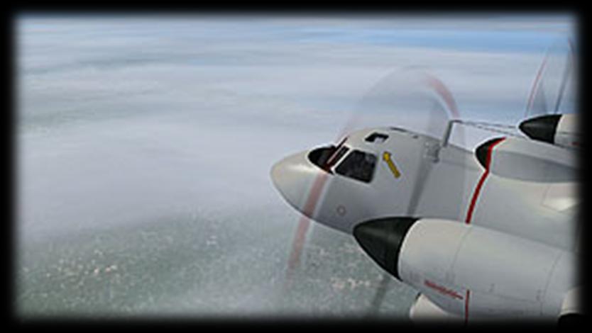
8 Tail View Nose View Cockpit View, Left 7

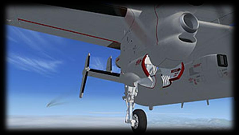
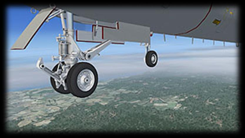
9 Cockpit View, Right Undercarriage View, Main Right Undercarriage View, Nose 8


10 Tail Hook View Interior Views It is possible to pan and zoom as normal in all interior views. Virtual Cockpit View Copilot s Seat View 9


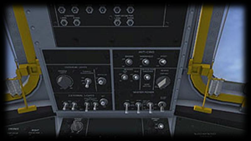
11 Cockpit Center View Cockpit Radios / Fire Panel View Cockpit Overhead Panel View 10


12 Cockpit Center Console View Cockpit Warning Lts / Stormscope View Moving Around the Cabin Shift-Enter and Shift-Backspace : moves up and down Ctrl-Shift-Enter and Ctrl-Shift-Backspace : moves side to side Ctrl-Enter and Ctrl-Backspace : moves backwards and forwards 11
 Angle of Attack (AoA) Indexer. The AOA indexer is comprised of three lights.")
13 Virtual Cockpit Functions Main Panel - left side 1) Landing Gear Not Down Warning Lamp. Flashes when flaps are down, either throttle is at less than 5% and gear is still retracted. 2) Angle of Attack (AoA) Indexer. The AOA indexer is comprised of three lights. The light indications are a green chevron ( v ) showing 'too high AOA' at the top, a yellow doughnut ( O ) showing proper AOA in the center, and a red chevron ( ^ ) showing 'too low AOA' at the bottom. 12
14 A GREEN chevron pointing down indicates too slow - the nose must be lowered and/or the throttle setting increased. An AMBER doughnut indicates that AOA is optimum for the approach. A RED chevron pointing up indicates too fast - the nose must be raised and/or the throttle setting reduced. At intermediate stages the AOA indexer may also display two symbols at a time. For example, a doughnut and a green chevron would indicate that the aircraft is nearing optimum AOA, providing the nose is lowered further. A doughnut and a red chevron would indicate the opposite. 3) Master Caution Light. Linked to the left and right Caution Light Panels, the Master Caution illuminates when any caution is registered. Clicking the lamp will reset it, but this should only be done after the Caution Light panel has been checked to see the cause of the alarm. 4) Angle of Attack Indicator. Shows the AoA in units, not actual degrees. The correct approach AoA of 20 units is indicated by the needle pointing at the 3-o'clock position. 5) Standby Artificial Horizon. This instrument provides a simplified safety backup to the main artificial horizon gauge. The right knob cages or locks in place both indicators during excessive maneuvering. 6) Clock. The knob can be clicked to toggle Local and Zulu time. 7) Airspeed Indicator. Shows the present airspeed in knots. 8) Main Artificial Horizon. The right side knob calibrates the indicator wings vertically. The instrument also has locator and glideslope needles so can be used for VOR (NAV1) homing, as well as an ILS receiver. Warning flags display when there is no valid LOC or GS signal, if there is no power and if the FSX Flight Director is switched on. 13
15 9) Radio Magnetic Indicator. A standard RMI with the larger needle for indicating the direction of the tuned NAV 1 station and the smaller needle for indicating the direction of the tuned NDB. The yellow heading bug indicates the current autopilot heading setting. 10) Flight Director Switch. This knob is used to toggle the FSX Flight Director function and the Main Artificial Horizon will display the information using its GS and LOC needles. 11) Radar Altimeter. The gauge has a SET knob which is used to move the small triangular bug around the perimeter of the gauge. The position of the bug indicates the set low altitude warning threshold, when the red warning lamp on the gauge will illuminate. 12) Altimeter. Standard altimeter, knob right side for Baro Setting. Use left/right mouse click, mousewheel or left click drag to adjust. An orange OFF flag will appear on the gauge face if power to the instrument is lost. 13) Vertical Speed Indicator. The Vertical Speed Indicator or VSI indicates the instantaneous rate of climb or descent in feet per minute. 14) Turn and Slip Indicator. The turn and slip indicator or turn and bank indicator is two flight instruments in one. One indicates the rate of turn, the other part indicates whether the aircraft is in coordinated flight. Enabling "Auto-Coordination" in FSX Settings will automate this. 15) Course Deviation Indicator. Functions like a ILS indicator with the aircraft symbol acting as a pointer indicating deviation left or right from the current set NAV1 OBS. The gauge includes the usual vertical and horizontal bars to indicate the relative direction of the tuned VOR or runway LOC and the glideslope (GS). The numerical display shows the current course (NAV1 OBS) setting and is adjusted using the knob at the bottom right of the gauge. Warning flags display when there is no valid LOC or GS signal. 16) Cockpit Lighting Switches. These two knobs toggle cabin (flood) lights and the instrument / text lighting. The flood light is best left off for night flying, especially on approach. 14
 Engine Torque Horsepower Indicators. The engine torque is displayed, expressed as Horsepower x 1000. 19) Engine Turbine Inlet Temperature Indicators.")
16 17) Accelerometer. The accelerometer measures acceleration (both negative and positive g-forces) during flight. The button is used to reset the minimum and maximum needles back to zero. 18) Engine Torque Horsepower Indicators. The engine torque is displayed, expressed as Horsepower x ) Engine Turbine Inlet Temperature Indicators. Records the temperature of the combustion gases as they enter the turbine section. 20) Engine Tachometers. These instruments indicate propeller and reduction gear speed in percent of RPM. 21) Engine Reducton Gear Oil Pressure Indicators. These indicate the pressure of the reduction gear lubricating oil at the outlet of the oil pumps. 22) Engine Power Section Oil Pressure Indicators. These display the pressure readings at the engine-driven oil pumps. 23) Engine Power Section Oil Temperature Indicators. These display the temperature of each engine s lubricating oil. Side Panel 1) Sim Icons. Quick links to FSX functions for ATC, Radios, GPS, Map, Kneeboard and Autopilot. The top icon will toggle the control yoke. 15
 and 4) Oil Cooler Flaps Switches. Open/close the flaps on the underside of the engine nacelles.")
17 2) NAV-GPS Switch. Toggles NAV1 and GPS to drive the autopilot when in CRS mode 3) Pilot Oxygen Supply Switch. Toggles supply on/off. The small meter above the switch displays the Oxygen pressure. The other two switches are animated but have no function in the model. Overhead Panel - left side 1) and 4) Oil Cooler Flaps Switches. Open/close the flaps on the underside of the engine nacelles. 2) and 3) Fuel Boost Pump Switches. Toggle the Boost Pumps. These are not essential to run the engines. 5) Fuel Dump Switch. This switch toggles the fuel dump system. When operated, fuel will be released from the left tank first until it is empty, then the right tank until it is empty. The fuel will be jettisoned from the tail of the aircraft and will take around 10 minutes to drain both tanks from full. A stream of atomized fuel will be visible at the rear of the aircraft. Only works when airborne for obvious reasons. 6) and 7) Engine Starter Switches. The Hawkeye does not actually have starter switches as the engines are run up using a ground starter unit. These switches have been added for convenience only and are not authentic, the real switches should control Fuel Enrich. 16
 NAV Radio Frequency Select Switch. This switch toggles the displayed frequency between the Active and the Standby.")
18 Overhead Panel - radios and fire 1) COM Radio Frequency Switches. Use left and right mouse clicks at the base of the switches to adjust the COM 1 active frequency. 2) and 5) NAV Radio Frequency Knobs. Use left and right mouse clicks to adjust the NAV 1 active frequency. 3) NAV Radio Frequency Select Switch. This switch toggles the displayed frequency between the Active and the Standby. 4) NAV Radio Swap Button. Pressing the spring-loaded button inserts the present Standby frequency into the display and sets the original Active frequency as Standby. 17
 Fire Warning Lamps Test Button.")
19 6) and 9) Emergency Engine Shutdown Handles. Pulling the handle out (left mouseclick) shuts down the engine. The red button which is then exposed will, when pressed, trigger the fire extinguisher and put out an engine fire in about 8 seconds. 7) Fire Warning Lamps Test Button. Pressing the spring-loaded button lights the Fire Warning lamps in the T-Bar handles. 8) Cabin Pressure Dump Switch. Activating this switch will gradually release the cabin pressure. The effect can be seen on the Cabin Pressure indicator on the copilot s panel. 10) Whiskey Compass. The familiar standby magnetic compass. Overhead Panel - electrics 1) Engine Anti-Icing Switch. 2) Pitot Heater Switch. 3) Instrument Lights Switch. 4) Cabin Lights Switch. 5) Wing & Tail Anti-Icing Switch. 6) Propeller Anti-Icing Switch. 18
 Bleed Air Overheat Lamps Test Switch. 2) Wing & Tail Anti-Ice Pressure Gauge. The gauge shows a reading when engine/wing anti-icing is switched on.")
20 7) Navigation Lights Switch. 8) Rotating Beacon Lights Switch. 9) Landing Lights Switch. 10) Left and Right Engine Generator Switches. 11) Master Battery Switch. Overhead Panel - left side 1) Bleed Air Overheat Lamps Test Switch. 2) Wing & Tail Anti-Ice Pressure Gauge. The gauge shows a reading when engine/wing anti-icing is switched on. 3) Wing & Tail Anti-Ice Suction Gauge. The gauge shows a reading when engine/wing anti-icing is switched on. 4) Prop Anti-Ice Ammeter. The gauge shows a reading when propeller anti-icing is switched on. 19
, as well as the six ACLS Message Indicator lights and the Air Data Computer annunciator block on the center")
21 Main Panel - center 1) Caution Lights Test Button. This spring-loaded button will force illumination of both clusters of caution lights (8), as well as the six ACLS Message Indicator lights and the Air Data Computer annunciator block on the center console. 2) Fuel & Oxygen Quantity Gauges Test Button. When pressed, the gauge needles will fall to zero to indicate proper functioning. 3) Oxygen Quantity Indicator. This gauge also has an OFF flag when there is no power to the instrument. 4) Cabin Pressure Indicator. The gauge will show normal ambient pressure up to 5,000ft above sea level. The system will then maintain 20
22 that value, unless the cabin pressure dump switch on the Fire Panel is used. In this case, the ambient pressure will be indicated on the gauge. Setting the dump switch back to ON will cause the cabin to be repressurized to 5,000ft ASL. 5) Fuel Quantity Indicators. These show the fuel remaining in pounds in each of the two tanks. 6) Stormscope. This gauge is a representation only. The real Stormscope is a form of weather radar. The top-right knob will toggle the instrument on/off, be prepared to wait for the system to boot up, this will take only a few seconds. The four buttons on the lower part of the gauge will display various authentic, but non-functional- screens of the Stormscope. 7) Fuel Flow Indicators. These show fuel flow to the engines in pounds per hour. 8) Caution Warning Lamp Clusters. Not all the warnings are supported by FSX, however the full range can be seen when the Caution Lights Test Button (1) is pressed. 21
 Clock. The knob can be clicked to toggle Local and Zulu time. 4) Master Caution Light.")
23 Main Panel - right side 1) Gear and Flaps Position Indicator. Shows landing gear and flaps position in and is mouseable. 2) Voltmeter. This gauge displays the voltage of the combined circuits of the aircraft. 3) Clock. The knob can be clicked to toggle Local and Zulu time. 4) Master Caution Light. Linked to the left and right Main Warning Panels, the Master Caution illuminates when any caution is registered. Clicking the lamp will reset it, but this should only be done after the Main Warning panel has been checked to see the cause of the alarm. 5) Trim Indicator. This gauge is mousable and can be used to adjust pitch, roll and yaw trim. 6) Airspeed Indicator. Shows the present airspeed in knots. 22
24 7) Main Artificial Horizon. The right side knob calibrates the indicator wings vertically. The instrument also has locator and glideslope needles so can be used for VOR (NAV1) homing, as well as an ILS receiver. Warning flags display when there is no valid LOC or GS signal, if there is no power and if the FSX Flight Director is switched on. 8) Radio Magnetic Indicator. A standard RMI with the larger needle for indicating the direction of the tuned NAV 1 station and the smaller needle for indicating the direction of the tuned NDB. The yellow heading bug indicates the current autopilot heading setting. 9) Hydraulic Pressure Indicators. These gauges display the pressure of the flight hydraulics and combined hydraulics systems. 10) Altimeter. Standard altimeter, knob right side for Baro Setting. Use left/right mouse click, mousewheel or left click drag to adjust. An orange OFF flag will appear on the gauge face if power to the instrument is lost. 11) Vertical Speed Indicator. The Vertical Speed Indicator or VSI indicates the instantanious rate of climb or descent in feet per minute. 12) Turn and Slip Indicator. The turn and slip indicator or turn and bank indicator is two flight instruments in one. One indicates the rate of turn, the other part indicates whether the aircraft is in coordinated flight. Enabling "Auto-Coordination" in FS Settings will automate this. 13) Course Deviation Indicator. The copilot has a simpler ILS instrument with the vertical locator (LOC) and horizontal glideslope bar (GS) to aid instrument landings. The gauge is driven by the NAV1 signal only. Warning flags are displayed when no LOC (VOR) or GS (glideslope) are being received. 14) Outside Air Temp. Indicator. The mouse tooltip displays the temperature in both Centigrade and Fahrenheit. 15) Cockpit Lighting Switches. These two knobs toggle cabin (flood) lights and the instrument / text lighting. The flood light is best left off for night flying, especially on approach. 23

25 Center Console 1) Air Data Computer Displays. Four banks of nixie lights display, from front to rear : Miles to Destination, Time to Destination, Aircraft Altitude and Speed, Ambient Wind Speed and Direction. 2) Air Data Computer on/off Switch. 3) Landing Gear Lever. Mousable. Right-click and drag backwards to extend gear. Right-click and drag forwards to retract gear. 24
26 4) Windshield Wiper Switch. Mousable. Click on right side to turn wipers on and left side to turn them off. The simulation only has one speed. 5) Engine Condition Levers. Control engine fuel flow. Setting the levers to the fully back position will shut down the engine. The levers can be moved independently with the mouse by dragging on any part of the lever. This does not affect engine performance in FSX. 6) Engine Throttle Levers. Control engine power delivery. The levers can be moved independently with the mouse by dragging on any part of the lever. 7) Wing Flaps Lever. Right-click and drag backwards to extend flaps. Right-click and drag forward to retract flaps. Has three positions, marked in degrees of rotation. 8) Tail Hook Lever. A Single mouse click will deploy the tail hook. Clicking again will retract it. 9) Parking Brake Lever. Click to activate the parking brake. 10) Autopilot Controls. Toggle switches left to right control : AP on/off, Attitude Hold, Approach Hold, Altitude Hold, Heading Hold and Course (NAV1) Hold. Note, the NAV-GPS switch on the pilot s left side console can be used to force CRS to track a GPS course rather than a NAV1 VOR. FSX does not support Speed Hold on turboprops, so careful management of the throttles is essential at all times. 11) Pitch Trim Adjuster. Use left or right mouse to move the switch forwards or aft respectively. As the switch is rather awkward to use in flight, it is recommended to use the keyboard or the Trim Indicator on the copilot s panel to adjust pitch trim. 25
27 REFERENCE INFORMATION Procedures Location of Starter Switches The starter switches are located on the pilot s upper panel. They are labelled as FUEL ENRICH. Mouse over each switch to confirm its function. Starting Engines Use Ctrl-E (autostart) to start the aircraft, or: 1. Check Parking Brake ON. 2. Check Crew Entrance Hatch is CLOSED. 3. Check Anti-Ice switches are OFF. 4. Check Generator Switches are ON. 5. Set throttles to IDLE. 6. Check Condition Levers at Air Start position (fully fwd). 7. Check Pitot Heat switch is OFF. 8. Set Prop Pitch to fully FINE (ctrl-f1). 9. Set Master Battery switch ON. 10. Set Navigation Lights switch to ON. 11. Set Rotating Beacon Lights switch to ON. 12. Start Engine 1 using the engine start switch. 13. Monitor engine RPM. Check that engine has not failed to start. Repeat for engine Check temperatures & pressures. Taxi 1. Set Pitot Heat ON. 2. Set Anti-Ice (as required) ON. 3. Navaids, Autopilot SET. 4. Set Parking Brake OFF. 5. Advance throttles to begin taxiing. 26
28 Takeoff 1. Check Autopilot OFF. 2. Check Wings Spread. 3. Set Pitot Heat ON. 4. Set flaps to takeoff (normal 25 %, 100 % if catapult launched). 5. Set nose-up Pitch Trim as required. 6. Brakes ON, maximum power CHECK. 7. Throttles to IDLE, Brakes OFF. 8. Set Holdback using shift-i (carrier take-off only). 9. Set Prop Pitch COARSE (default FSX setting, ctrl-f4 if needed). 10. Apply power smoothly to full throttle. 11. Press shift-spacebar to trigger catapult (carrier take-off only) 12. Begin Rotation at approx. 100 KTS IAS (land take-off only). After Takeoff 1. When airborne, raise GEAR. 2. At 125 KTS raise FLAPS. 3. Allow the aircraft to accelerate to normal climb speed 154 KTS. Cruising 1. Level off at desired cruise altitude. 2. Reduce throttle setting. 3. Adjust speed to cruise at 260 KTS. 4. Use autopilot to set cruise parameters (shift-2). Descent 1. Begin descent 40 miles from the airfield or carrier. 2. Check Pitot Heat ON. 3. Set descent rate and speed as desired using the autopilot (shift-2). Approach 1. Set Autopilot OFF. 2. Check Parking Brake OFF. 3. Set Altimeter Baro Pressure to match landing zone pressure. 4. Lower Landing Gear BELOW 190 KTS. 5. Enter downwind leg at 175 KTS. 6. Set Flaps to 25%. 7. Check AOA Indexer to maintain correct attitude. 8. Lower Arresting Hook (if required). 27
29 Landing 1. Check Autopilot is OFF. 2. Maintain 120 KTS. 3. Set FLAPS FULLY DOWN. 4. Adjust throttles to compensate for drag. 5. Visual check airfield / deck is safe for landing. 6. Sink Rate not greater than 500 ft/min. 7. Touchdown speed is 110 KTS. 8. Ground Landing only : prop reverse ENGAGE (press & hold F2). 9. Apply brakes only below 80 KTS. 10. Carrier Landing only : set Throttles to FULL (in case of bolter). After Landing / Wire Trap 1. Set Throttles to IDLE. 2. Set Arresting Hook UP (carrier landing only). 3. Set Flaps fully UP (ground landing only). 4. Set Flaps to 1/3 (carrier landing only). 5. Fold Wings (carrier landing only). 6. Begin taxi to parking area (ground landing only). Shutdown 1. Stop engines using Condition Levers. 2. Set Pitot Heat and all external lights to OFF. 3. Set all cockpit and cabin lighting to OFF. 4. Set Generator Switches to OFF. 5. Set Master Battery Switch to OFF. 28
30 E-2C Hawkeye Specifications and Speed References Specifications Crew: 5 Engines: 2 x Allison T56-A-425 Turboprops Power: 4,600 i.h.p. each Wingspan: 80' 7" (29 4 folded) Length: 57' 7" Height: 18' 4 Empty Weight : 39,561 lbs Combat Weight : 48,040 lbs MTOW : 53,000 lbs Max. Landing Weight : 46,500 lbs (field or arrested) Flight Reference Data Maximum speed : 330 kts at 15,000 ft Average cruising speed / altitude : 260 kts at 25,000 ft Ferry Range : 1,462 nautical miles Service Ceiling : 34,700 ft Max. Fuel Load : 12,220 lbs Stalling Speed, dirty, max. weight power off : 93 kts Stalling Speed, dirty, max weight power on : 75 kts Stalling Speed, clean, max. weight power off : 112 kts Stalling Speed, clean, max weight power on : 90 kts 29
Convair XB-46 USER MANUAL. Virtavia XB-46 Manual Version DTG 1.0
 Convair XB-46 USER MANUAL 0 Introduction For the 1944 jet bomber competition, Consolidate Vultee (which became Convair) offered their model 109, which featured four Allison J-35-C-3 jet engines slung under
HU-16 Albatross USER MANUAL. Virtavia HU-16 Albatross DTG Steam Edition Manual Version 1.0
 HU-16 Albatross USER MANUAL 0 Introduction The Grumman HU-16 Albatross is a twin-engine amphibious flying boat. First flown in 1949, the HU-16 underwent a number of modifications and improvements over
USER MANUAL Virtavia Pty Ltd B-29 Superfortress Manual Version 1.0
 B-29 SUPERFORTRESS USER MANUAL 0 Introduction The Boeing B-29 Superfortress was a giant leap forward in bomber technology and production by the U.S. during WWII. Design studies for a "super bomber" were
A-6E Intruder USER MANUAL. Virtavia A-6E Intruder DTG Steam Edition Manual Version 2.0
 A-6E Intruder USER MANUAL 0 Introduction The Grumman A-6 was the US Navy's premier precision strike aircraft for over 30 years. First introduced in 1963, the A-6 saw extensive service in Vietnam and continued
Boeing B-47 Stratojet USER MANUAL. Virtavia B-47E Stratojet DTG Steam Edition Manual Version 2
 Boeing B-47 Stratojet USER MANUAL 0 Introduction The Boeing B-47 was the first swept-wing multi-engine bomber in service with the USAF. It was truly a quantum leap in aviation history, and is the forerunner
F-5E Tiger II USER MANUAL. Virtavia F-5E Tiger II DTG Steam Edition Manual Version 2.0
 F-5E Tiger II USER MANUAL 0 Introduction The F-5E Tiger II is an improved version of the original F-5 Freedom Fighter that entered service with the US Military in the early 1960s. It is a lightweight,
North American F-86F Sabre USER MANUAL. Virtavia F-86F Sabre DTG Steam Edition Manual Version 1
 North American F-86F Sabre USER MANUAL 0 Introduction The F-86 Sabre was a natural replacement for the F-80 Shooting Star. First introduced in 1949 for the United States Air Force, the F-86 featured excellent
The cockpit. UFCD Upfront control display. Head up display. Right DDI - Digital display indicator. Left DDI - Digital display indicator
 Super Hornet The cockpit Head up display Left DDI - Digital display indicator Fuel gauge / engine gauge Landing gear lever UFCD Upfront control display Right DDI - Digital display indicator HUD settings
Vso 61. Vs1 63. Vr 70. Vx 76. Vxse 78. Vy 89. Vyse. 89 (blue line) Vmc. 61 (radial redline) Vsse 76. Va 134) Vno 163
 Vmc. 61 (radial redline) Vsse 76. Va 134) Vno 163") PA34-200T Piper Seneca II Normal procedures V-speeds Knots Vso 6 Vs 63 Vr 70 Vx 76 Vxse 78 Vy 89 Vyse Vmc 89 (blue line) 6 (radial redline) Vsse 76 Va 2-36(@4507lbs 34) Vno 63 Vfe 38 (0*)/2(25*)/07(40*)
PA34-200T Piper Seneca II Normal procedures V-speeds Knots Vso 6 Vs 63 Vr 70 Vx 76 Vxse 78 Vy 89 Vyse Vmc 89 (blue line) 6 (radial redline) Vsse 76 Va 2-36(@4507lbs 34) Vno 63 Vfe 38 (0*)/2(25*)/07(40*)
Cessna 172P PPL Checklist Page 1
 Cessna 172P PPL Checklist 06-08-2017 Page 1 Cessna 172P PPL Checklist 06-08-2017 Page 2 Checklist Items Informational Items Critical Memory Items PREFLIGHT COCKPIT CHECK (DO-LIST) Pitot Cover -- REMOVE
OPERATIONS MANUAL FTO SECTION : 06.04
 06.04.08. OO-WIK SECTION : 06.04 PARTENAVIA OO-WIK PAGE : 1 PRE ENTRY PITOT COVER - REMOVE SNOW / ICE CHECK AIRCRAFT NOSE INTO WIND AIRCRAFT WEIGHT & BALANCE WITHIN LIMITS EXTERNAL (COCKPIT FIRST) PARK
V - Speeds. RV-10 V fe Flaps Speeds Trail (0 deg) Half (15 deg) Full (30 deg) 122 kias 96 kias. 80 kias
 Half (15 deg) Full (30 deg) 122 kias 96 kias. 80 kias") RV-10 Check List V - Speeds RV-10 V fe Flaps Speeds Trail (0 deg) Half (15 deg) Full (30 deg) 122 kias 96 kias 87 kias V s1 Stall (Flap Up) 60 kias V s0 Stall (Flap 40 deg) 55 kias Best Glide 80 kias V
RV-10 Check List V - Speeds RV-10 V fe Flaps Speeds Trail (0 deg) Half (15 deg) Full (30 deg) 122 kias 96 kias 87 kias V s1 Stall (Flap Up) 60 kias V s0 Stall (Flap 40 deg) 55 kias Best Glide 80 kias V
PA GURW (December 30, 2000) PRE-START. Langley Flying School. Airspeeds (MPH) for Safe Operation. Cockpit Checks
 PRE-START. Langley Flying School. Airspeeds (MPH) for Safe Operation. Cockpit Checks") Langley Flying School PA-34-200 GURW (December 30, 2000) Airspeeds (MPH) for Safe Operation V y (all weights) 105 V x (all weights) 90 En Route Climb 120 V mc 80 V yse 105 V xse 93 V r 80 V r (25 Flaps)
Langley Flying School PA-34-200 GURW (December 30, 2000) Airspeeds (MPH) for Safe Operation V y (all weights) 105 V x (all weights) 90 En Route Climb 120 V mc 80 V yse 105 V xse 93 V r 80 V r (25 Flaps)
by Greg Whiley Aussie Star Flight Simulation
 Flying the BAe 146 200/300 Version 2 by Greg Whiley Aussie Star Flight Simulation INTENTIALLY LEFT BLANK Greg Whiley Aussie Star Flight Simulation 2 Version Date Revision Version 1.0 25 June 2014 Original
North American XB-70A Valkyrie USER MANUAL. Virtavia XB-70A Valkyrie DTG Steam Edition Manual Version 1
 North American XB-70A Valkyrie USER MANUAL 0 Introduction A technological tour de force of epic proportions, the legend of the XB- 70 Valkyrie very nearly surpasses the performance of this extraordinary
The engines are designed to use 100/130 octane fuel. If not available use next higher grade. - 1
 PNEUMATIC SYSTEM The aircraft has a dual pneumatic system. In case of failure of either pneumatic pump, the system will automatically select the operative source. (Inoperative source will be indicated
NORMAL PROCEDURRES CHECKLIST PA T SENECA II PREFLIGHT CHECK INSIDE CABIN OUTSIDE CABIN
 NORMAL PROCEDURRES CHECKLIST PA-34-200T SENECA II PREFLIGHT CHECK INSIDE CABIN Avionics Master Switch -- OFF Landing Gear Control. -- DOWN Mixture Controls -- IDLE/CUTOFF Ignition Switches -- OFF Master
I. DISPATCH PLANNING & AIRCRAFT EXTERIOR CHECK
 SCHODACK AVIATION Page 1 of 10 I. DISPATCH PLANNING & AIRCRAFT EXTERIOR CHECK 1. Flight Planning 1. Aircraft requirements & preparation: Required aircraft documents: Airworthiness Certificate Registration
Dassault Falcon 50 Microsoft Flight Simulator 2004
 Dassault Falcon 50 Microsoft Flight Simulator 2004 Model and bitmaps Yannick Lavigne Custom gauge programming Fred Banting Flight dynamics Rob Young and Eric Dantes. Foto: Gerry Stegmeier Foto: Dassault
CESSNA SECTION 4. Unless otherwise noted, the following speeds are based on a maximum weight of 2550 pounds and may be used for any lesser weight.
 CESSNA SECTION 4 INTRODUCTION Section 4 provides procedures and amplified instructions for normal operations using standard equipment. Normal procedures associated with optional systems can be found in
DIAMOND DA40 PILOTS MANUAL
 DIAMOND DA40 PILOTS MANUAL INTRODUCTION THIS IS THE SLEEK AND FUTURISTIC DIAMOND STAR DA40 XLS BY DIAMOND AIRCRAFT CORPORATION. THE DIAMOND STAR FEATURES 4 SEATS, AND OPTIONAL EXPANDED REAR CARGO AREA,
I. DISPATCH PLANNING & AIRCRAFT EXTERIOR CHECK
 SCHODACK AVIATION Page 1 of 10 I. DISPATCH PLANNING & AIRCRAFT EXTERIOR CHECK 1. Flight Planning 1. Aircraft requirements & preparation: 1. Required aircraft documents: 1. Airworthiness Certificate 2.
Cirrus SR20 Microsoft Flightsimulator 2002
 Cirrus SR20 Microsoft Flightsimulator 2002 Aircraft and Panel : Günter Kraemer Werner Schott Günter Kraemer Switzerland Germany w.schott@abbts.ch guenter@kraemerg.de Page 12 Page 1 Other simulator checklists
Interior Pre Flight Documents: Check Control Wheel Lock: Remove Flight Controls: Check Instruments: Check for Damage Switches: Verify All Off Master
 Interior Pre Flight Documents: Check Control Wheel Lock: Remove Flight Controls: Check Instruments: Check for Damage Switches: Verify All Off Master Switch ALT/BAT: On Fuel Gauge: Check Quantity Flaps:
Piper Archer II (PA )
") 1. Oil... 6-8 qts, Cap Secure CABIN 1. POH & Documents.. Check Available 2. Magneto Switch...... OFF 3. Pitot/Static Drains... Push to Drain 4. Avionics/Electrical Switches... OFF 5. Master Switch. ON
1. Oil... 6-8 qts, Cap Secure CABIN 1. POH & Documents.. Check Available 2. Magneto Switch...... OFF 3. Pitot/Static Drains... Push to Drain 4. Avionics/Electrical Switches... OFF 5. Master Switch. ON
David s Flight Simulator Operations Manual
 DPW Solutions David s Flight Simulator Operations Manual Draft 0.2 David Woolterton Update 10/5/2016 Table of Contents Pre-Start Checklist... 2 Startup Checklist... 3 Before Taxi Checklist... 3 Taxi Checklist...
CESSNA 182 CHECKLIST. LEFT WING Trailing Edge 1. Aileron CHECK freedom of movement and security
 CESSNA 182 CHECKLIST PRE-FLIGHT INSPECTION CABIN 1. Pilot s Operating Handbook AVAILABLE IN THE AIRPLANE (A.R.R.O.W.E) 2. Landing Gear Lever DOWN 3. Control Wheel Lock REMOVE 4. Ignition Switch OFF 5.
INDEX: Normal Procedures Emergency Procedures Pre Flight Inspection NORMAL PROCEDURES BEFORE STARTING ENGINE
 INDEX: Normal Procedures Emergency Procedures Pre Flight Inspection NORMAL PROCEDURES BEFORE STARTING ENGINE 1. Preflight Inspection -- COMPLETE 2. Seats, Belts, Shoulder Harnesses -- ADJUST and LOCK 3.
Com Active/Standby Frequency Switch. C om Active/Standby Frequencies. Terrain. Flight Plan. Button. Button
 ALABEO GNS530 Nav Active/Standby Frequency Switch Com Active/Standby Frequency Switch C om Active/Standby Frequencies Zoom In/Out Button Nav Active/Standby Frequencies On/Off Button Direct To Button Nav1
King Air B90. Speeds (KIAS)
") King Air B90 Speeds (KIAS) V MCA 92 V SSE (101) Derived from C90 V X 101 V Y 114 Down to 103 @ 30 000 V XSE 101 V YSE 110 Down to 101 @ 24 000 V A 169 V R 92 V 1 101 V MO 208 V FE 174 35% 130 100% V LE
King Air B90 Speeds (KIAS) V MCA 92 V SSE (101) Derived from C90 V X 101 V Y 114 Down to 103 @ 30 000 V XSE 101 V YSE 110 Down to 101 @ 24 000 V A 169 V R 92 V 1 101 V MO 208 V FE 174 35% 130 100% V LE
REFERENCE: 2861 wings 2044 trunk 4904 total BEW 10,655 BOW 11,185 Max Useful load 5115 MLanding ZFW FUEL BURNS 11min min min
 REFERENCE: 2861 wings 2044 trunk 4904 total BEW 10,655 BOW 11,185 Max Useful load 5115 MLanding 15700 ZFW 13000 FUEL BURNS 11min 357 27min 730 36 min 940 58min 1453 1:17 1800 2:20 2933 2:46 3283 3:00 3600
Normal T/O Procedure. * * * Engine Failure on T/O * * *
 Normal T/O Procedure After adding full power: Engine Instruments green Airspeed alive 1,000 AGL Accelerate to enroute climb 113 KIAS Set climb power Vr 78, but it will come off the ground before Stay in
CHECKLIST 1969 CESSNA 172-K. NOTE: Verify all information with airplane's POH
 CHECKLIST 1969 CESSNA 172-K NOTE: Verify all information with airplane's POH PRE-FLIGHT INSPECTION 1 CABIN 1 A.R.R.O.W. CHECK Airworthiness Cert. In Clear View Registration In Clear View Radio License
INDEX. Preflight Inspection Pages 2-4. Start Up.. Page 5. Take Off. Page 6. Approach to Landing. Pages 7-8. Emergency Procedures..
 INDEX Preflight Inspection Pages 2-4 Start Up.. Page 5 Take Off. Page 6 Approach to Landing. Pages 7-8 Emergency Procedures.. Page 9 Engine Failure Pages 10-13 Propeller Governor Failure Page 14 Fire.
Su-33 Flanker Volume Multi-Role carrierborne fighter-bomber.
 Lock-On Modern Air Combat Check-lists Su-33 Flanker Volume Multi-Role carrierborne fighter-bomber. Not suited for Real Operations For Lomac use only. Each lomac aircraft will have its checklists volume.
Best Glide 75 kias (Max Gross)
") CESSNA 172XP CHECKLIST PREFLIGHT (Interior) 1. ACFT DOCS / INSPECTIONS--------CHECK 2. TACH TIME-----------------------------RECORD 3. CONTROL LOCK---------------------REMOVE 4. ELEVATOR / RUDDER TRIM------------
CESSNA 172XP CHECKLIST PREFLIGHT (Interior) 1. ACFT DOCS / INSPECTIONS--------CHECK 2. TACH TIME-----------------------------RECORD 3. CONTROL LOCK---------------------REMOVE 4. ELEVATOR / RUDDER TRIM------------
Expanded Flight Checklist Cessna 152
 OUTSIDE CHECK INSIDE CABIN 1 Magnetos... OFF 2 Mixture... IDLE CUT OFF 3 Master switch... ON 4 Fuel quantity... CHECKED 5 Master switch... OFF OUTSIDE CABIN 1 Left wing... CHECKED Surface condition Flap
AIRPLANE GENERAL Exterior REV 3, May 03/05
 Vol. 1 01--20--1 AIRPLANE GENERAL Exterior REV 3, May 03/05 24 ft 1 in (7.34 m) 5ft1in(1.55m) 10 ft 7 in (3.23 m) 6ft4in (1.93 m) 81 ft 6 in (24.85 m) 9ft6in(2.89m) 8ft10in (2.69 m) 36 ft 4 in (11.07 m)
N955DK RV-8A David B. Kumhyr. N955DK Version 05Nov04 RV-8A
 N955DK RV-8A David B. Kumhyr Operating Speeds Reference VREF Flight Regime Kts Mph Vso Stall, dirty (gross)... Stall, dirty (solo).. 50 58 Vs.. Stall, clean (gross)... Stall, clean (solo). 55 63 Vr.. Rotation.
OVERHEAD PANEL PROCEDURES FLASH CARDS
 OVERHEAD PANEL PROCEDURES FLASH CARDS Boeing 737-800 A supplement to the procedures and checklists publication, Flying the Boeing 737-800 NG Greg Whiley Aussie Star Flight Simulation ELECTRICAL POWER UP
Van s Aircraft RV-7A. Pilot s Operating Handbook N585RV
 Van s Aircraft RV-7A Pilot s Operating Handbook N585RV PERFORMANCE SPECIFICATIONS SPAN:..25 0 LENGTH...20 4 HEIGHT:.. 7 10 SPEED: Maximum at Sea Level...180 knots Cruise, 75% Power at 8,000 Ft...170 knots
CESSNA 172S NAV III VFR CHECKOUT POH EXAMINATION (Based on N1129K, serial no. 172S revised 10/05/06)
") INTRODUCTION, POH CESSNA 172S NAV III VFR CHECKOUT POH EXAMINATION (Based on N1129K, serial no. 172S10315 - revised 10/05/06) 1. Rate of climb at sea level: 2. Service ceiling: 3. Takeoff performance,
INTRODUCTION, POH CESSNA 172S NAV III VFR CHECKOUT POH EXAMINATION (Based on N1129K, serial no. 172S10315 - revised 10/05/06) 1. Rate of climb at sea level: 2. Service ceiling: 3. Takeoff performance,
Normal Takeoff Procedure. Aborted Takeoff Procedure Engine Failure on Takeoff
 Normal Takeoff Procedure Throttles 2000 RPM Engine Instruments Green Smoothly apply full throttles Airspeed alive V R 90 MPH Remain in ground effect until V MCA 1000 AGL or safe altitude Accelerate to
Pilot's Operating Handbook Supplement AS-03
 POH / AFM SECTION 9 Pilot's Operating Handbook Supplement ASPEN EFD1000 PFD This supplement is applicable and must be inserted into Section 9 of the POH when the Aspen Avionics Evolution Flight Display
FLIGHT HANDLING NOTES CHECK LIST & PERFORMANCE DATA GROB G 109B G-KNEK
 FLIGHT HANDLING NOTES CHECK LIST & PERFORMANCE DATA GROB G 109B G-KNEK Before Starting Engine PREFLIGHT CHECK COMPLETED. 1. Adjust pedals and back rests 2. Adjust and secure seat harness 3. Folding doors
AIRPLANE FLIGHT MANUAL AQUILA AT01 AIRPLANE FLIGHT MANUAL - SUPPLEMENT AVE28 GLASS COCKPIT. equipped with ASPEN EFD1000 PFD
 SECTION 9 AIRPLANE FLIGHT MANUAL - SUPPLEMENT AVE28 GLASS COCKPIT equipped with ASPEN EFD1000 PFD This AFM supplement is applicable and must be inserted into Section 9 of the Airplane Flight Manual when
DCS L-39 ALBATROS REAL PILOT START-UP, TAXI AND TAKEOFF CHECKLISTS V 1.0 PREPARED BY LINO_GERMANY
 DCS L-39 ALBATROS REAL PILOT START-UP, TAXI AND TAKEOFF CHECKLISTS V 1.0 PREPARED BY LINO_GERMANY T.O. 1T-L39C-1.0 P1 INTRODUCTIONS A. CHECKLISTS This compilation contains amplified normal and (hopefully
Flight checklist for normal operations Massgebend ist das AFM (parameters, restrictions, emergency, etc.)
") JAN13 1 Flight checklist for normal operations Massgebend ist das AFM (parameters, restrictions, emergency, etc.) Cockpit preparation before starting engine 1 Aircraft + Cockpit inspection completed (according
JAN13 1 Flight checklist for normal operations Massgebend ist das AFM (parameters, restrictions, emergency, etc.) Cockpit preparation before starting engine 1 Aircraft + Cockpit inspection completed (according
CESSNA P 337 H Pressurized Skymaster
 CESSNA P 337 H Pressurized Skymaster N777SN Quick reference training guide This training manual cannot be used as a substitute for the official pilots operating handbook. Page 1 - 1. Take off (normal)
Examen Teórico sobre Habilitación de Tipo B (Última actualización: Septiembre 2016)
") DIRECCIÓN GENERAL DE AERONÁUTICA CIVIL DEPARTAMENTO SEGURIDAD OPERACIONAL SUBDEPARTAMENTO LICENCIAS Examen Teórico sobre Habilitación de Tipo B-737-300 (Última actualización: Septiembre 2016) Materia:
DIRECCIÓN GENERAL DE AERONÁUTICA CIVIL DEPARTAMENTO SEGURIDAD OPERACIONAL SUBDEPARTAMENTO LICENCIAS Examen Teórico sobre Habilitación de Tipo B-737-300 (Última actualización: Septiembre 2016) Materia:
FLASHCARDS AIRCRAFT. Courtesy of the Air Safety Institute, a Division of the AOPA Foundation, and made possible by AOPA Services Corporation.
 AIRCRAFT FLASHCARDS Courtesy of the Air Safety Institute, a Division of the AOPA Foundation, and made possible by AOPA Services Corporation. Knowing your aircraft well is essential to safe flying. These
Preflight Inspection Cabin EMPENNAGE RIGHT WING Trailing Edge RIGHT WING NOSE
 Preflight Inspection Cabin 1. Control Wheel Lock REMOVED 2. Ignition Switch OFF 3. Avionics Power Switch OFF 4. Master Switch ON 5. Fuel Quantity Indicators CHECK QUANTITY 6. Master Switch OFF 7. Fuel
Pilot Training C150 CHECKLIST
 Gunnedah Aero Club Pilot Training C150 CHECKLIST How to use the checklist. Conduct the checks up to (but not including the start) by memory. Then, use the checklist to confirm the checks were completed.
FIRST FLYING TECHNIQUES COCKPIT PREPARATION STARTUP TAXI
 1. Introduction FIRST FLYING TECHNIQUES COCKPIT PREPARATION STARTUP TAXI We aim to teach and demonstrate how to operate a general aviation aircraft and show some basic techniques and manoeuvres that every
Jump to Table of Contents
 Jump to Table of Contents PIPER AIRCRAFT CORPORATION PA-28R-201, CHEROKEE ARROW III SECTION 3 EMERGENCY PROCEDURES 3.3 EMERGENCY PROCEDURES CHECK LIST ENGINE FIRE DURING
Takeoff Flaps UP 2000
 Takeoff Flaps UP 2000 30 60 75 80 85 V1 Gear UP Flap Position Indicator blanked 10 seconds after flaps UP Asymmetry Protection Near Zero Yaw Automatic unlock all surfaces (maintenance) Speedbrakes auto
Cessna 152 Checklist
 Cessna 152 Checklist This checklist covers the operation of the model 152. Use at your own risk, the author nor the publisher is responsible for any damage or accidents resulting from the use of this checklist.
Elmendorf Aero Club Aircraft Test
 DO NOT WRITE ON THIS TEST FEB 2014 Elmendorf Aero Club Aircraft Test Cessna - 185 For the following questions, you will need to refer to the Pilots Information Manual for the C-185F and Graphic Engine
DO NOT WRITE ON THIS TEST FEB 2013 Elmendorf Aero Club Aircraft Test. Cessna - 182
 DO NOT WRITE ON THIS TEST FEB 2013 Elmendorf Aero Club Aircraft Test Cessna - 182 For the following questions, you will need to refer to the Pilots Information Manual for the C-182R. The bonus questions
PA , Model E Normal Checklist (04/15/11)
") PA-23-250, Model E Normal Checklist (04/15/11) Key Airspeeds IAS-MPH V NE 249 V NO 198 V LO/LE 150 V A (At max gross weight.) 149 Speed for single engine cruise. 138 V FE Quarter Flaps 160 Half Flaps 140
PA-23-250, Model E Normal Checklist (04/15/11) Key Airspeeds IAS-MPH V NE 249 V NO 198 V LO/LE 150 V A (At max gross weight.) 149 Speed for single engine cruise. 138 V FE Quarter Flaps 160 Half Flaps 140
* Transit flight deck preparation
 Page 1 Explanations * Transit flight deck preparation Procedures By heart items FFD OUTSIDE CHECK INSIDE CABIN First flight a day 1 Crossfeed drain... DRAINED - Drain crossfeed left hand of left forward
IN-FLIGHT CHECK LIST B-17 Technical Session for Flight Engineers 11/18/2017 (with REVISION)
") IN-FLIGHT CHECK LIST B-17 Technical Session for Flight Engineers 11/18/2017 (with REVISION) Check Lists became an integral part of aviation following the tragic loss of Boeing 299 the prototype for the
IN-FLIGHT CHECK LIST B-17 Technical Session for Flight Engineers 11/18/2017 (with REVISION) Check Lists became an integral part of aviation following the tragic loss of Boeing 299 the prototype for the
Cessna 172 Skyhawk. Aircraft Checklist Models: R & S
 Cessna 172 Skyhawk Aircraft Checklist Models: R & S This is an abbreviated checklist. Most explanatory items, notes cautions and warnings have been omitted for brevity. Procedures in red/bold text in this
Elmendorf Aero Club Aircraft Test
 DO NOT WRITE ON THIS TEST FEB 2013 Elmendorf Aero Club Aircraft Test Cessna - 182 For the following questions, you will need to refer to the Pilots Information Manual for the C-182R. The bonus questions
Messerschmitt 262A-1a For Microsoft Flight Simulator 2004
 1 Messerschmitt 262A-1a For Microsoft Flight Simulator 2004 Thank you for your purchase of this FS2004 aircraft. It aims to give you a precise and detailed visual feeling for this unique aircraft, the
NORMAL CHECKLIST ATTENTION!
 Avion Training CHECKLIST Normal Checklist CESSNA 172R / TC-STS Cessna 172 R TC-STS NORMAL CHECKLIST ATTENTION! DO NOT STOW THIS CHECKLIST IN DIRECT SUNLIGHT Avion Training - Doc.nr. 212 Revision 1 / 02022018
CARENADO COPYRIGHTS. Normal & Emergency Checklist
 NORMAL PROCEDURES CHECKLIST PREFLIGHT CHECK Control wheel -- RELEASE BELTS Avionics -- OFF Master Switch -- ON Fuel quantity gauges -- CHECK Master switch -- OFF Ignition -- OFF Exterior -- CHECK FOR DAMAGE
PREFLIGHT CHECK COCKPIT RIGHT WING. NORMAL PROCEDURRES CHECKLIST PA-28RT 201 Arrow IV
 NORMAL PROCEDURRES CHECKLIST PA-28RT 201 Arrow IV PREFLIGHT CHECK COCKPIT Control Wheel -- Release Restraints Avionics -- OFF Parking Brake -- SET All Switches -- OFF Mixture -- IDLE CUT-OFF Master Switch
Flight Procedures Aero AT-3 R100
 Flight Procedures Page: 1 1. FOREWORD... 3 2. FLIGHT PREPARATION... 3 3. PRE-FLIGHT CHECK... 3 3.1. External inspection:... 4 3.2. In the cockpit... 4 3.3. Left wing... 5 3.4. Engine nacelle, canopy and
Checklist for Bellanca Viking N4880V (Speeds in MPH (KTS) IAS)
 IAS)") V-SPEEDS Checklist for Bellanca Viking N4880V V SO 62 (54) Stall Full Flaps V S1 72 (63) Stall Clean V R 80 (70) Takeoff Rotation Flaps Up V Y 110 (96) Best Rate Gear Up & Flaps Up V R 70 (61) Takeoff
V-SPEEDS Checklist for Bellanca Viking N4880V V SO 62 (54) Stall Full Flaps V S1 72 (63) Stall Clean V R 80 (70) Takeoff Rotation Flaps Up V Y 110 (96) Best Rate Gear Up & Flaps Up V R 70 (61) Takeoff
M20J-201 Checklist BEFORE STARTING ENGINE
 M20J-201 Checklist BEFORE STARTING ENGINE Preflight... COMPLETE Baggage door... LATCHED/LOCKED Door... LATCHED/LOCKED Seatbelts... FASTENED Passenger brief....... [seatbelts/exits/smoking/talking/traffic]
Elmendorf Aero Club Aircraft Test
 DO NOT WRITE ON THIS TEST FEB 2013 Elmendorf Aero Club Aircraft Test Cessna - 172 For the following questions, you will need to refer to the Pilots Information Manual for the C-172R (180hp). The bonus
Aircraft Checklist Cessna 182T
 Aircraft Checklist Cessna 182T This is an abbreviated checklist. Most explanatory items, notes cautions and warnings have been omitted for brevity. Procedures in red/bold in this checklist should be committed
Section 1: List of Configurations Currently Approved:
 Section 1: List of Configurations Currently Approved: 1. Configuration: TD2 BASIC-Standard - Single Engine, Land, Optional Fixed or Retractable Gear, Optional Fixed Pitch or Constant Speed Propeller, Optional
AIRSPEEDS. Cessna 172R Emergency Checklist
 AIRSPEEDS AIRSPEEDS FOR EMERGENCY OPERATION Cessna 172R Emergency Checklist INTRODUCTION This document provides checklist and amplified procedures for coping with emergencies that may occur. Emergencies
Mig-29A FulcrumA & Mig-29S FulcrumC Short range air to air fighter with limited air to ground capability.
 Lock-On Modern Air Combat Check-lists Mig-29A FulcrumA & Mig-29S FulcrumC Short range air to air fighter with limited air to ground capability. Not suited for Real Operations For Lomac use only. Each lomac
JODEL D.112 INFORMATION MANUAL C-FVOF
 JODEL D.112 INFORMATION MANUAL C-FVOF Table of Contents I General Description...4 Dimensions:...4 Powertrain:...4 Landing gear:...4 Control travel:...4 II Limitations...5 Speed limits:...5 Airpeed indicator
CHAPTER 1 AIRCRAFT GENERAL
 CHAPTER 1 AIRCRAFT GENERAL INTRODUCTION This manual provides a description of the major airframe and engine systems in the Cessna Citation Mustang (Figure 1-1). This material does not supersede, nor is
Tie down IAS-TAS Table 14
 PA28-161- 1 Piper PA28-161 Archer II Cockpit Interior Exterior Check Exterior Check [cont.] Before Start Engine Start After Start ENG Flooded Start Start with External Pwr Run-Up Before Takeoff Short Field
PREFLIGHT. Cessna 152 Checklist. Review Aircraft Maintenance Status Sheet Parking Brake. Certificates, POH, & Wt & Bal Check
 Cessna 152 list PREFLIGHT CABIN Review Aircraft Maintenance Status Sheet Parking Brake Control Lock Remove Certificates, POH, & Wt & Bal Avionics All E.L.T. Battery Switch Fuel Indicators Down All Switches
Automatic Flight Chapter 4
 Automatic Flight Chapter 4 Table of Contents Section 0 4.0 Automatic Flight-Table of Contents Controls and Indicators................................ 4.10.1 Mode Control Panel (MCP).............................
Flight Checklist for Normal Operations Massgebend ist das AFM (Parameters, Restrictions, Emergency, etc.)
") Flight Checklist for Normal Operations Massgebend ist das AFM (Parameters, Restrictions, Emergency, etc.) Jan18 1 COCKPIT PREPARATION BEFORE STARTING ENGINE 1 Aircraft + Cockpit Inspection COMPLETED 1
Flight Checklist for Normal Operations Massgebend ist das AFM (Parameters, Restrictions, Emergency, etc.) Jan18 1 COCKPIT PREPARATION BEFORE STARTING ENGINE 1 Aircraft + Cockpit Inspection COMPLETED 1
Cessna 182S-CHECKLIST PROCEDURES
 Cessna 182S-CHECKLIST PROCEDURES PREFLIGHT INSPECTION 1 CABIN 1. Pitot Tube Cover -- REMOVE (if installed) and check for stoppage 2. Pilot s Operating Handbook AVAILABLE IN THE AIRPLANE 3. Airplane Weight
CHAPTER 2 THE TUTOR. Introduction
 CHAPTER 2 THE TUTOR Introduction 1. AEFs. The Royal Air Force has 12 units throughout the country known as Air Experience flights (AEFs). Their role is to provide air experience flying for cadets and they
Boeing /-200/-200A Limitations
 Boeing 727-100/-200/-200A Limitations The information provided in this document is to be used during simulated flight only and is not intended to be used in real life. Attention VA's - you may post this
The Straight Word. Cessna 208 Caravan 208 Caravan I & 208B Grand Caravan Series
 The Straight Word Cessna 208 Caravan 208 Caravan I & 208B Grand Caravan Series I. FLIGHT PROCEDURES: COCKPIT PREPARATION Fuel Tank Selectors Ignition Switch Heading Bug HSI Course Indicator Altimeters
USAF Aero Club T-41B (Cessna R-172E) Aircraft Exam Updated February 2017
 Aircraft Exam Updated February 2017") USAF Aero Club T-41B (Cessna R-172E) Aircraft Exam Updated February 2017 Instructions Complete the supplement following exam using the answer sheet provided. Do not assume information not specifically
USAF Aero Club T-41B (Cessna R-172E) Aircraft Exam Updated February 2017 Instructions Complete the supplement following exam using the answer sheet provided. Do not assume information not specifically
XIV.C. Flight Principles Engine Inoperative
 XIV.C. Flight Principles Engine Inoperative References: FAA-H-8083-3; POH/AFM Objectives The student should develop knowledge of the elements related to single engine operation. Key Elements Elements Schedule
S A F E T Y NORMAL PROCEDURES NORMAL PROCEDURES BEFORE STARTING ENGINE PASSENGER SAFETY BRIEFING STARTING ENGINE
 PRE-FLIGHT PRE-FLIGHT BEFORE STARTING ENGINE PASSENGER SAFETY BRIEFING 1. Preflight Inspection COMPLETE 2. Passenger Safety Briefing COMPLETE 3. Seats, Belts, Shoulder Harnesses ADJUST AND LOCK 4. Fuel
DCS:C Quick Start Guide Version 1.0 FOREWORD
 DCS:C-101 - Quick Start Guide Version 1.0 FOREWORD The commissioning of the CASA C-101 in 1981 coincided with the appearance of the first personal computer, the Intel 8088 powered IBM XT desktop computer.
X-Plane 11 King Air C90B
 Pilot s Operating Manual Author: Julian Lockwood (julian@x-plane.com) Copyright: Laminar Research 2017 X-Plane 11 King Air C90B Disclaimer The information contained in this document is for simulation use
The Straight Word. Beechcraft 90 King Air B90 Series. Condition Lever. Set for Takeoff Cabin Altitude Controller Set Cruise Level + 1
 The Straight Word Beechcraft 90 King Air B90 Series I. FLIGHT PROCEDURES: COCKPIT PREPARATION Heading Bug Set QFU HSI Course Indicator Set Course Altimeters Set QNH Power Levers Idle Propeller Levers Max
IntelliFlight 2100 Programmer/Computer PN Software Mod Code L or Later WAAS Capable Pilot s Operating Handbook
 IntelliFlight 2100 Programmer/Computer PN 01304 Software Mod Code L or Later WAAS Capable Pilot s Operating Handbook NAV VS 500 ALT 12 5 00 List of Effective Pages * Asterisk indicates pages changed, added,
FLIGHT REPLICAS. DC-4/C-54/Carvair. For Lockheed Martin Prepar3D v4
 1 FLIGHT REPLICAS DC-4/C-54/Carvair For Lockheed Martin Prepar3D v4 This is a complex simulation. To get full enjoyment of the aircraft in this package, please read this Manual thoroughly and carefully.
PA-28R 201 Piper Arrow
 Beale Aero Club Aircraft Written Test PA-28R 201 Piper Arrow (Required passing score: 80%) 1. If an engine power loss occurs immediately after take off, the pilot s reaction should be to: a. maintain safe
FINAL EXAM. 3. Name the items on the control shift in the unmodified aircraft (non ASC-36).
.") FINAL EXAM Name 1. Total usable fuel is 177 gallons 2. Proper fuel(s) specification for the T-28 is (are): XX (a) 100/130 alternate 100LL (b) 115/145 and 100/130 alternate (c) 115/145 and 100/130 emergency
FINAL EXAM Name 1. Total usable fuel is 177 gallons 2. Proper fuel(s) specification for the T-28 is (are): XX (a) 100/130 alternate 100LL (b) 115/145 and 100/130 alternate (c) 115/145 and 100/130 emergency
PA34-220T Piper Seneca III
 PREFLIGHT PA34-220T Piper Seneca III Weight and Balance Documents -Airworthiness Certificate -Registration -Airplane Flight Manual -Weight & Balance Hobbs/Time Landing Gear Avionics and Fan(s) Cowl Fuel
QUICK REFERENCE HANDBOOK TECNAM P92 ECHO
 NORMAL LISTS PRE-START S Park brake Left fuel cock Flight Instruments (No broken glass or bent needles) Engine Instruments (No broken glass or bent needles) Right fuel cock Fuses Landing Light Avionics
COLUMBIA 350 EMERGENCY PROCEDURES
 COLUMBIA 350 EMERGENCY PROCEDURES TABLE OF CONTENTS EMERGENCY PROCEDURES LANDING AND TAKEOFF Engine Failure During Takeoff...1 Engine Failure Immediately After Takeoff...1 Engine Failure During Climb to
LOG OF REVISIONS. Model G58 Baron (Serials TH-2125 and After) Pilot s Operating Handbook and FAA Approved Airplane Flight Manual
 Pilot s Operating Handbook and FAA Approved Airplane Flight Manual") LOG OF REVISIONS Model G58 Baron (Serials TH-2125 and After) Pilot s Operating Handbook and FAA Approved Airplane Flight Manual Revision A12 - May, 2015 Title Page LOEP LOR Section 1 All Reformatted to
LOG OF REVISIONS Model G58 Baron (Serials TH-2125 and After) Pilot s Operating Handbook and FAA Approved Airplane Flight Manual Revision A12 - May, 2015 Title Page LOEP LOR Section 1 All Reformatted to