Reliability Test Report
|
|
|
- Bruce Powell
- 5 years ago
- Views:
Transcription
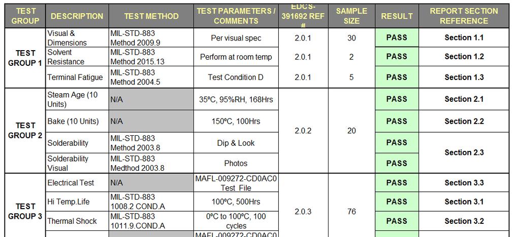
1 Reliability Test Report Page 1 of 29
2 Reliability flow Chart: Page 2 of 29
3 Test Group Dimensional Analysis: Test Purpose: These measurements are to verify that the units meet the dimensional specifications outlined in the data sheet Test Method/Specification: Refer to dimensional section of MAFL CD0AC0 data sheet See Figure 1.1A Figure 1.1A - MAFL CD0AC0 outline dimensions Page 3 of 29
4 1.1.3 Measurement Results: Sample(s) Description: MAFL CD0AC0 Quantity: 30 PCS All 30 samples measured meet the data sheet dimensional specifications. The measurement results can be seen in Figure 1.1B. Figure 1.1B Dimensional results Page 4 of 29
 Inspection before Test: Sample(s) Description: MAFL-009272-CD0AC0 Quantity: 2 PCS (1#, 2#) Appearance Inspection: No visual damage was found on samples before test.")

 to the extent that they cannot be readily identified from a distance of")
5 1.2 Solvent Resistance Test: SGS Report Reference: SZRL06006F/2009 Section Test Purpose: The purpose of this test is to verify that the markings will not become illegible on the component parts when subjected to solvents Test Method/Specification: Refer to Mil-STD-883G Method Appearance Inspection: Appearance inspection performed before and after test Sample(s) Inspection before Test: Sample(s) Description: MAFL CD0AC0 Quantity: 2 PCS (1#, 2#) Appearance Inspection: No visual damage was found on samples before test. See Photo 1.2A Test Procedure: Lab Environmental Conditions: Ambient temperature: 25±3ºC, Relative humidity: 55±20%RH Test Result(s): Standard s failure criteria: After subjection to the test, evidence of damage to the device and any specified markings which are missing in whole or in part, faded, smeared, blurred, or shifted (dislodged) to the extent that they cannot be readily identified from a distance of at least 15.0 cm (6 inches) with normal room lighting and without the aid of magnification or with a viewer having a magnification no greater than 3X shall constitute a failure. Appearance Inspection: No visual damage was found on samples after test. See Photo 1.2B. Photo 1.2A Samples Before Test Photo 1.2B Samples After Test Page 5 of 29

6 1.3 Terminal Fatigue Testing: SGS Report Reference: SZRL06006F/2009 Section Test Purpose: This test is designed to check the capabilities of the device solder pads to withstand a delamination (peel) stress of specified tension and time Test Method/Specification: Refer to Mil-STD-883G Method condition D. Test Condition: A minimum tension of 8 ounces (2.22 N) shall be applied, without shock, to each solder pad to be tested in a direction perpendicular to the solder pad surface and maintained for 30 seconds minimum. Test Profile: Appearance Inspection: Appearance inspection performed before and after test Sample(s) Inspection before Test: Sample(s) Description: MAFL CD0AC0 Quantity: 5 PCS (3#~7#) Appearance Inspection: No visual damage was found on samples before test. See Photo 1.3C Test Procedure: Test Equipment: Name: Model: Testometric CMT6503 Equipment No. : Lab Environmental Conditions: Ambient temperature: 25±3ºC, Relative humidity: 55±20%RH. Page 6 of 29

")
 or wire breakage")
7 1.3.6 Test Result(s): Standard s failure criteria: When examined, using 10X magnification, after removal of the tension stress, the appearance of any delamination involving constituent solder pad interfaces shall be considered an adhesion failure of the solder pad. Separation of the solder pad from the device is an obvious (without visual magnification) adhesion failure. Separation of the wire from the solder fillet (leaving the solder pad intact) or wire breakage is considered a test procedure failure. Photo 1.3C Sample Before Test Photo 1.3D Sample After Test Page 7 of 29


: Appearance Check: No visual damage was found on samples after test. See Photo 2.1C. Photo 2.1B Samples Before Test Photo 2.")
8 Test Group Steam Age Test: SGS Report Reference: SZRL06006F/2009 Section Test Purpose: The test aim is to verify the samples ability to resist the environment conditions Test Method/Specification: Refer to client s requirements. Test Temperature: 35ºC Test Humidity: 95%RH Test Duration: 168hours Appearance Inspection: Appearance inspection performed before and after test Sample(s) Inspection before Test: Sample(s) Description: MAFL CD0AC0 Quantity: 10 PCS Appearance Inspection: No visual damage was found on samples before test. See Photo 2.1B Test Procedure: Test Equipment: Name: Model: Temp & Humidity Chamber ETH-B0-100 Equipment No. : POLY-I-242 Lab Environmental Conditions: Ambient temperature: 25±3ºc, Relative humidity: 55±20%RH Test Result(s): Appearance Check: No visual damage was found on samples after test. See Photo 2.1C. Photo 2.1B Samples Before Test Photo 2.1C Samples After Test Page 8 of 29


9 2.2 Bake Test: SGS Report Reference: SZRL06006F/2009 Section Test Purpose: The test aim is to verify the samples ability to resist the environment conditions Test Method/Specification: Refer to client s requirements. Test Temperature: 150ºC Test Duration: 100hours Appearance Inspection: Appearance inspection performed before and after test Sample(s) Inspection before Test: Sample(s) Description: MAFL CD0AC0 Quantity: 10 PCS Appearance Inspection: No visual damage was found on samples before test. See Photo 2.2B Test Procedure: Test Equipment: Name: Model: Thermal Shock Chamber TS300 Equipment No. : SZREL-010 Lab Environmental Conditions: Ambient temperature: 25±3ºc, Relative humidity: 55±20%RH Test Result(s): Appearance Check: No visual damage was found on samples after test. See Photo 2.2C Photo 2.2B Samples Before Test Photo 2.2C Samples After Test Page 9 of 29

10 2.3 Solderability Test: Test Purpose: The purpose of this test is to verify the solderability of the samples subjected to the steam age and bake testing outlined in sections 2.1 & Test Method/Specification: Refer to Mil-STD-883 Method Dip and Look solderability Test. Solder Temperature 245ºC ± 5 ºC Solder: SN60 Immersion rate: 1 per second ± 0.25 per second Dwell Time: 5 seconds ± 0.5 second Appearance Inspection: Appearance inspection performed before and after test Sample(s) Inspection before Test: Sample(s) Description: MAFL CD0AC0 Quantity: 10 PCS after Steam age test. 10PCS after Bake test. Appearance Inspection: No visual damage was found on samples before test Test Result(s): Appearance Check: Samples checked using magnification of 10-15x. All samples meet the criteria for acceptable solderability. The solder coverage is >95% See Photo 2.3A Photo 2.3A Sample After Solderability Test Page 10 of 29

: Appearance Check: No visual damage was found on samples after test.")
11 Test Group 3: 3.1: High Temperature Life Stabilization Bake Test: SGS Report Reference: SZRL06006F/2009 Section Test Purpose: The purpose of this test is to determine the effect on microelectronic devices of storage at elevated temperatures without electrical stress applied Test Method/Specification: Refer to Mil-STD-883G Method condition A. Test Temperature: 100ºC Test Duration: 500hours Appearance Inspection: Appearance inspection performed before and after test Sample(s) Inspection before Test: Sample(s) Description: MAFL CD0AC0 Quantity: 76 PCS Appearance Inspection: No visual damage was found on samples before test. See Photo 3.1B Test Procedure: Test Equipment: Name: Model: Ramp Temperature Cycling Chamber WK-800/70/25 Equipment No. : SZREL-009 Lab Environmental Conditions: Ambient temperature: 25±3ºC, Relative humidity: 55±20%RH Test Result(s): Appearance Check: No visual damage was found on samples after test. See Photo 3.1C. Photo 3.1B Sample Before Test Photo 3.1C Sample After Test Page 11 of 29


12 3.2: Thermal Shock Test: SGS Report Reference: SZRL06006F/2009 Section Test Purpose: The purpose of this test is to determine the resistance of the part to sudden exposure to extreme changes in temperature and the effect of alternate exposures to these extremes Test Method/Specification: Refer to Mil-STD-883G Method condition A. Low Temperature: 0ºC. High Temperature: 100 ºC. Dwell Time: 10 minutes. Test Cycles: 100. Total duration: about 34 hours Appearance Inspection: Appearance inspection performed before and after test Sample(s) Inspection before Test: Sample(s) Description: MAFL CD0AC0 Quantity: 76 PCS (after Hi temp Life Stabilization Bake Test). Appearance Inspection: No visual damage was found on samples before test. See Photo 3.2C Test Procedure: Test Equipment: Name: Model: Thermal Shock Chamber TS300 Equipment No. : SZREL-010 Lab Environmental Conditions: Ambient temperature: 25±3ºC, Relative humidity: 55±20%RH Test Result(s): Appearance Check: No visual damage was found on samples after test. See Photo 3.2D. Photo 3.2C Sample Before Test Photo 3.2D Sample After Test Page 12 of 29
13 3.3: Functional Test: Initial Functional Test Results The 76 units were functionally tested for Insertion loss before being subjected to High Temperature Life Stabilization Bake and Thermal Shock outlined in sections 3.1 & 3.2. All 76 units passed to specification. The initial test results are plotted in Figure 3.3A below. 5 Port1_reflection Port2_port3_transmission Page 13 of 29
14 Port1_port2_transmission Port1_port3_transmission Figure 3.3A Test Plots before Temperature Testing. Page 14 of 29
15 3.3.2 Functional Test Results After Temperature testing The 76 units were functionally re-tested after High Temperature Life Stabilization Bake and Thermal Shock. All 76 units continue to pass specification. The test results after Temperature testing are plotted in Figure 3.3B below. 5 Port1_reflection Port2_port3_transmission Page 15 of 29
16 Port1_port2_transmission Port1_port3_transmission Figure 3.3B Test Plots after Temperature Testing. Page 16 of 29
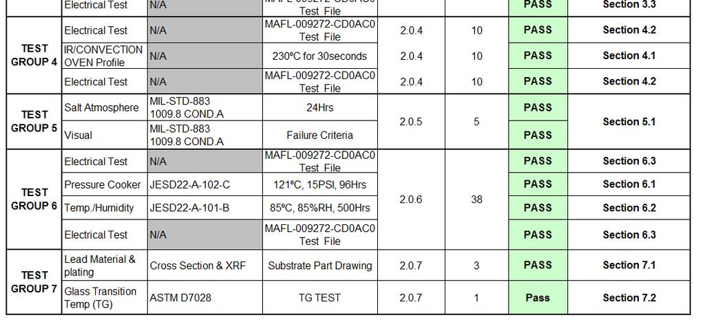
17 Test Group 4: 4.1 Convection Oven Profile: Test Purpose: The purpose of this test is to determine the resistance of the part to high temperature experienced during Convection Oven reflow Test Method/Specification: Refer to client s reflow requirements. Test Temperature: 230ºC Test Duration: 30seconds. See Figure 4.1A Figure 4.1A-Reflow Profile Appearance Inspection: Appearance inspection performed before and after test Sample(s) Inspection before Test: Sample(s) Description: MAFL CD0AC0 Quantity: 10 PCS Appearance Inspection: No visual damage was found on samples before test. See Photo 4.1B Test Procedure: Test Equipment: 7 Zone Convection Reflow Oven. Page 17 of 29


18 4.1.6 Test Result(s): Appearance Check: No visual damage was found on samples after test. See Photo 4.1C. Photo 4.1B Samples Before Test Photo 4.1C Samples After Test 4.2: Functional Test After Reflow: Functional Test Results after Convection Reflow The 10 finished good units were functionally tested for Insertion Loss after the Convection oven reflow outlined in section 4.1. All 10 units pass functional specification after reflow. The test results after Convection oven reflow are plotted in Figure 4.2A below. 5 Port1_reflection Page 18 of 29
19 Page 19 of 29 Port2_port3_transmission Port1_port2_transmission Port1_port3_transmission Figure 4.2A Test Plots after Reflow.

20 Test Group 5: 5.1 Salt Atmosphere Test: SGS Report Reference: SZRL06006F/2009 Section Test Purpose: This test provides a controlled corrosive environment which has been utilized to produce relative corrosion resistance information for specimens of metals and coated metals exposed in a given test chamber Test Method/Specification: Refer to Mil-STD-883G Method condition A. Concentration of salt solution: 0.5% 3.0% NaCl (m/m) Chamber temperature: 35ºC PH of salt solution at (35±2) ºC: Exposure period: 24h Appearance Inspection: Appearance inspection performed before and after test Sample(s) Inspection before Test: Sample(s) Description: MAFL CD0AC0 Quantity: 5 PCS Appearance Inspection: No visual damage was found on samples before test. See Photo 5.1A Test Procedure: Test Equipment: Name: Salt Spray Chamber Model: CEEC-YW-150 Equipment No. : Lab Environmental Conditions: Ambient temperature: 25±3ºC, Relative humidity: 55±20%RH Test Result(s): Standard s failure criteria: a) Corrosion defects over more than 5 percent of the area of the finish or base metal of any package element other than leads such as lid, cap, or case. b) Leads missing, broken, or partially separated. c) Specified markings, which are missing in whole or in part, faded, smeared, blurred, shifted, or dislodged to the extent that they are not legible. Appearance Inspection: No visual damage was found on samples before test. See 5.1B Photo 5.1A Samples Before Test Photo 5.1B Samples After Test Page 20 of 29


21 Test Group 6: 6.1 Pressure Cooker Test: SGS Report Reference: SZRL06006F/2009 Section Test Purpose: This test is performed to evaluate the moisture resistance integrity of non-hermetic packaged solid state devices using moisture condensing or moisture saturated steam environments Test Method/Specification: Refer to JESD22-A-102-C and client s requirements. Vapor pressure: 15 PSI Test Temperature: 121ºC Test Duration: 96hours Appearance Inspection: Appearance inspection performed before and after test Sample(s) Inspection before Test: Sample(s) Description: MAFL CD0AC0 Quantity: 38 PCS Appearance Inspection: No visual damage was found on samples before test Test Procedure: Test Equipment: Name: Pressure Cooker Tester Brand: KSON Model: PCT-S/S022 Lab Environmental Conditions: Ambient temperature: 25±3ºC, Relative humidity: 55±20%RH Test Result(s): Appearance Check: No visual damage was found on samples after test. See Photo 6.1B Photo 6.1B Sample After Test Page 21 of 29


22 6.2 Temp/Humidity Test: SGS Report Reference: SZRL06006F/2009 Section Test Purpose: This test is performed for the purpose of evaluating the reliability of non-hermetic packaged solid-state devices in humid environments Test Method/Specification: Refer to JESD22-A-101-B and client s requirements. Test Temperature: 85ºC Test Humidity: 85%RH Test Duration: 500hours Appearance Inspection: Appearance inspection performed before and after test Sample(s) Inspection before Test: Sample(s) Description: MAFL CD0AC0 Quantity: 38 PCS (after Pressure Cooker Test) Appearance Inspection: No visual damage was found on samples before test. See Photo 6.2B Test Procedure: Test Equipment: Name: Triple Temp & Humidity Chamber Brand: GIANT FORCE Model: GTH-162TR-SP/MAA Lab Environmental Conditions: Ambient temperature: 25±3ºC, Relative humidity: 55±20%RH Test Result(s): Appearance Check: Slight Oxidation after test but acceptable. See Photo 6.2C. Photo 6.2B Sample Before Test Photo 6.2C Samples After Test Page 22 of 29
23 6.3: Functional Test: Initial Functional Test Results: The 38 units were functionally tested for Insertion loss before being subjected to Pressure Cooker and Temp/Humidity testing outlined in sections 6.1 & 6.2. All 38 units passed to specification. The initial test results are plotted in Figure 6.3A below. 5 Port1_reflection Port2_port3_transmission Page 23 of 29
24 Port1_port2_transmission Port1_port3_transmission Figure 6.3A Test Plots before Pressure Cooker and Temp/Humidity testing. Page 24 of 29
25 6.3.2 Functional Test Results After Pressure & Humidity testing: The 38 units were functionally re-tested after Pressure Cooker and Temp/Humidity testing. All 38 units continue to pass specification. The test results after Temperature testing are plotted in Figure 6.3B below. 5 Port1_reflection Port2_port3_transmission Page 25 of 29
26 Port1_port2_transmission Port1_port3_transmission Figure 6.3B Test Plots after Pressure Cooker and Temp/Humidity testing. Page 26 of 29
 0.1")
27 Test Group 7: 7.1 Lead Material & plating: Test Purpose: Measurements performed to verify that the lead plating thickness and composition meet specification Test Method/Specification: Refer to Substrate material drawing CTJC000 for plating specification. Plating Thickness: o Ni: 3-5µm, o Au: (flash) µm Sample(s) Inspection before Test: Sample(s) Description: MAFL CD0AC0 Quantity: 3 PCS Appearance Inspection: No visual damage was found on samples before test Test Procedure: XRF and cross sectional analysis Test Results: Lead plating on all samples meet the required thickness and composition specifications. See Photo 7.1A Photo 7.1A- Cross Section of sample and thickness measurements. Page 27 of 29
 Inspection before Test: 7.")

28 7.2 Glass Transition Test: Test Purpose Test Method/Specification Sample(s) Inspection before Test: Test Setup Photo 7.2A Sample Before Test Page 28 of 29

29 Photo 7.2B Sample During Test Test Results: Photo 7.2C Profile for Tg Test Page 29 of 29
VIA Platform Environmental Qualification Testing Standards
 VIA Platform Environmental Qualification Testing Standards Revision: 1 Report Dated: September 7 th 2016 Report Prepared By: Noel Joyce Reliability Lab Manager Page 1 of 16 Table of Contents 1. Purpose...
TEST REPORT Report No.: HCO0127/2006 Page: 1 of 9 Date: November 1, 2006
 Page: 1 of 9 Date: November 1, 2006 ZIBO MICRO COMMERCIAL COMPONENTS CORP. ZHANG LIU ROAD, ZHANGDIAN DISTRICT, ZIBO, SHANDONG, P.R. CHINA The following merchandise was submitted and identified by the vendor
WW25X, WW18X, WW12X, WW08X, WW06X ±1%, ±5% Thick Film Current Sensing Chip Resistors Size 2512, 1218, 1206, 0805, 0603 (Automotive)
") WW25X, WW18X, WW12X, WW08X, WW06X ±1%, ±5% Thick Film Current Sensing Chip Resistors Size 2512, 1218, 1206, 0805, 0603 (Automotive) *Contents in this sheet are subject to change without prior notice. Page
WW25X, WW18X, WW12X, WW08X, WW06X ±1%, ±5% Thick Film Current Sensing Chip Resistors Size 2512, 1218, 1206, 0805, 0603 (Automotive) *Contents in this sheet are subject to change without prior notice. Page
MIL-STD-883G METHOD LEAD INTEGRITY
 LEAD INTEGRITY 1. PURPOSE. This method provides various tests for determining the integrity of microelectronic device leads (terminals), welds, and seals. Test condition A provides for straight tensile
PRODUCT SPECIFICATION
 1. SCOPE This specification covers the T-FLASH MEMORYCARD SOCKET series. 2. PRODUCT NAME AND PART NUMBER Product Name Part Number Assembly 49225-811 Embossed Package 49225-811 3. RATINGS Item Standard
HIGH SPEED MEZZANINE PRODUCT SPECIFICATION
 OARD TO OARD CONNECTOR 75005 Receptacle Assembly 75003 Plug Assembly Table of Contents 1.0 Scope 2.0 Product Description 3.0 Applicable Documents and Specifications 4.0 Ratings 5.0 Performance 5.1 Qualification
PTC Thermistor for Automotive:TPM-C Series
 Features 1. Qualification based on AEC-Q200 Rev-C 2. RoHS & Halogen-free compliant 3. EIA size 0603,0805 4. Fast and reliable response Recommended Applications 1. Automotive electronics Part Number Code
Jun 20,2014 Rev A
 Product Specification 108-115067 Jun 20,2014 Rev A DDR4 DIMM Through-hole Memory Socket 1. SCOPE 1.1. Content This specification covers performance, tests and quality requirements for the TE Connectivity
PTC Thermistor for Automotive:TPM-C Series
 SMD PTC Thermistor for Features 1. Qualification based on AEC-Q200 Rev-C 2. RoHS & Halogen-free compliant 3. EIA size 0603,0805 4. Fast and reliable response Recommended Applications 1. Automotive electronics
Features. V max (Vdc) I max (A) typ. (W) P d
 I max (A) typ. (W) P d") 2016L Series RoHS Description The 2016L Series PTC provides surface mount overcurrent protection for low voltage ( 60V applications where resettable protection is desired. Features RoHS compliant, lead-free
2016L Series RoHS Description The 2016L Series PTC provides surface mount overcurrent protection for low voltage ( 60V applications where resettable protection is desired. Features RoHS compliant, lead-free
WA04X, WA06X ±1%, ±5%, Convex Type General purpose chip resistors array
 WA04X, WA06X ±1%, ±5%, Convex Type General purpose chip resistors array Size 0402x4, 0603x4 (8p4R) (Automotive ) Page 1 of 8 ASC_WAxxX_J_V05 May.2011 FEATURE 1. Small size and light weight 2. Reduced size
Surface Mount > 0603L Series. Description. Features. Applications. Maximum Time To Trip Current (A) P d typ. (W)
 P d typ. (W)") 0603L Series RoHS Description The 0603L Series PTC provides surface mount overcurrent protection for applications where space is at a premium and resettable protection is desired. Features Agency Approvals
0603L Series RoHS Description The 0603L Series PTC provides surface mount overcurrent protection for applications where space is at a premium and resettable protection is desired. Features Agency Approvals
NTC Thermistor for Automotive: TSM-C Series
 Features 1. Qualification based on AEC-Q200 Rev-C 2. Operating temperature range: -50 ~ +150 3. Superior stability in high-temperature and high-humidity environment 4. RoHS & Halogen Free (HF) compliant
POLY-FUSE Resettable PTCs. 2920L Series. Surface Mount > 2920L Series E R RoHS. Description
 2920L Series RoHS Description The 2920L Series PTC provides surface mount overcurrent protection for medium voltage ( 60V applications where resettable protection is desired. Features RoHS compliant, lead-free
Features. Samples. I max (A) P d. typ. (W)
 P d. typ. (W)") 0805L Series RoHS Description The 0805L Series PTC provides surface mount overcurrent protection for applications where space is at a premium and resettable protection is desired. Features Agency Approvals
0805L Series RoHS Description The 0805L Series PTC provides surface mount overcurrent protection for applications where space is at a premium and resettable protection is desired. Features Agency Approvals
Surface Mount > 1210L Series. Description. Features. Applications. Maximum Time To Trip Current (A) P d typ. (W) Time (Sec.)
 P d typ. (W) Time (Sec.)") 1210L Series RoHS Description The 1210L Series PTC provides surface mount overcurrent protection for applications where space is at a premium and resettable protection is desired. Features Agency Approvals
1210L Series RoHS Description The 1210L Series PTC provides surface mount overcurrent protection for applications where space is at a premium and resettable protection is desired. Features Agency Approvals
Cold Resistance (Ohm) Note 1
 Note 1") P700L Series Part Numbering System P700L - 72-1.0 Fuse Type Voltage Amp Part Number/Rating Cold Resistance (Ohm) Note 1 Overload Interrupt Time (Second) Nominal Rating - Note 2/3 Maximum I 2 T (Ampere
P700L Series Part Numbering System P700L - 72-1.0 Fuse Type Voltage Amp Part Number/Rating Cold Resistance (Ohm) Note 1 Overload Interrupt Time (Second) Nominal Rating - Note 2/3 Maximum I 2 T (Ampere
Surface Mount > 1812L Series. Description. Features. Applications. I max (A) typ. (W) P d. Current (A)
 typ. (W) P d. Current (A)") 1812L Series RoHS Description The 1812L Series PTC provides surface mount overcurrent protection for applications where resettable protection is desired. Features RoHS compliant, lead-free and halogen-free
1812L Series RoHS Description The 1812L Series PTC provides surface mount overcurrent protection for applications where resettable protection is desired. Features RoHS compliant, lead-free and halogen-free
PRODUCT SPECIFICATION
 1.0mm Pitch ZIF FPC Page 1 Top Entry Side Entry 1.0mm Pitch ZIF FPC Page 2 1.0 SCOPE. This specification covers performance, tests and quality requirements for 1.0mm Pitch ZIF FPC Connector 2.0 APPLICABLE
WR10, WR12, WR08, WR06, WR04 ±1%, ±5% General purpose chip resistors. Size 1210, 1206, 0805, 0603, 0402
 WR10, WR12, WR08, WR06, WR04, General purpose chip resistors Size 1210, 1206, 0805, 0603, 0402 ( Automotive & Anti-sulfuration ) *Contents in this sheet are subject to change without prior notice. Page
MA04X, MA06X ±1%, ±5%, Convex Type General purpose chip resistors array
 MA04X, MA06X ±1%, ±5%, Convex Type General purpose chip resistors array Size 0402x4, 0603x4 (8p4R) ( Automotive & Anti-sulfur ) Page 1 of 8 MA04/ 06_V03 Apr.2010 FEATURE 1. High reliability and stability
WR12, WR08, WR06, WR04 ±1%, ±5% General purpose chip resistors. Size 1206, 0805, 0603, ( Automotive )
") WR12, WR08, WR06, WR04 ±1%, ±5% General purpose chip resistors Size 1206, 0805, 0603, 0402 ( Automotive ) Page 1 of 9 WR_J(AUTO)_ V03 Sep.2010 FEATURE 1. Automotive grade AEC Q-200 compliant 2. 100% CCD
WR12, WR08, WR06, WR04 ±1%, ±5% General purpose chip resistors Size 1206, 0805, 0603, 0402 ( Automotive ) Page 1 of 9 WR_J(AUTO)_ V03 Sep.2010 FEATURE 1. Automotive grade AEC Q-200 compliant 2. 100% CCD
SPECIFICATION SHEET P700L CURRENT LIMITING FUSE SURFACE MOUNT MODEL
 11525 Sorrento Valley Rd. San Diego, California 92121 (858) 481-0210 SPECIFICATION SHEET P700L CURRENT LIMITING FUSE SURFACE MOUNT MODEL REVISION: A B C D E F G H J DATE: 10/95 2/96 2/00 10/95 2/96 10/98
SM1206 Series. Overload Interrupt Time (Second) Nominal Rating - Note 2. Cold Resistance (Ohm) Note 1. Maximum I 2 T (Ampere 2 Second) Nominal Rating
 Nominal Rating - Note 2. Cold Resistance (Ohm) Note 1. Maximum I 2 T (Ampere 2 Second) Nominal Rating") SM1206 Series Part Numbering System SM1206-32 - 1.0 Fuse Type Voltage Amp Part Number/Rating Cold Resistance (Ohm) Note 1 Overload Interrupt Time (Second) Nominal Rating - Note 2 Maximum I 2 T (Ampere
SM1206 Series Part Numbering System SM1206-32 - 1.0 Fuse Type Voltage Amp Part Number/Rating Cold Resistance (Ohm) Note 1 Overload Interrupt Time (Second) Nominal Rating - Note 2 Maximum I 2 T (Ampere
SPECIFICATION SHEET. ±1%, ±5%, Convex Type General purpose chip resistors array
 SPECIFICATION SHEET CNA24, CNA34 ±1%, ±5%, Convex Type General purpose chip resistors array Size 0402x4, 0603x4 (8p4R) ( Automotive & Anti-sulfur ) All data in this sheet are subject to change, modify
Size 1206, 1210, 0805, 0603, 0402 (Anti-Sulfuration )
") SR12, SR10, SR08, SR06, SR04, General purpose chip resistors Size 1206, 1210, 0805, 0603, 0402 (Anti-Sulfuration ) *Contents in this sheet are subject to change without prior notice. Page 1 of 9 ASC_SR_V03
SR12, SR10, SR08, SR06, SR04, General purpose chip resistors Size 1206, 1210, 0805, 0603, 0402 (Anti-Sulfuration ) *Contents in this sheet are subject to change without prior notice. Page 1 of 9 ASC_SR_V03
Reference Only. Spec.No. JENF243H-0008M-01 P 1/ 14. Rated Current. Withstanding Voltage 20A 125V (DC) (DC) 250V (DC) 20A (DC) 20A 40V (DC) (DC) (DC)
 (DC) 250V (DC) 20A (DC) 20A 40V (DC) (DC) (DC)") Spec.No. JENF243H-0008M-01 P 1/ 14 SMD Block Type EMIFIL BNX02-01 Reference Specification 1.Scope This reference specification applies to SMD Block Type EMIFIL. 2.Part Numbering BN X 022-01 L Product ID
Spec.No. JENF243H-0008M-01 P 1/ 14 SMD Block Type EMIFIL BNX02-01 Reference Specification 1.Scope This reference specification applies to SMD Block Type EMIFIL. 2.Part Numbering BN X 022-01 L Product ID
l-tech C O M P A N Y Issue by Engineering Department Product 8.4"Rugged LCD : Model WRD0840 Product Description Test Reason
 l-tech Thermal Test Report Issue by Engineering Department Product Model Product Description Report No:0807TT0239 8.4"Rugged LCD : WRD0840 New product Rugged Display A/D Board :i-tech / R5W-310 Rugged
The World Leader in High Performance Signal Processing Solutions. QMI2569 Conductive Ag Glass Adhesive Qualification Data
 The World Leader in High Performance Signal Processing Solutions QMI2569 Conductive Ag Glass Adhesive Qualification Data QUALIFICATION TEST RESULTS The following tests have been completed on qualification
POLYFUSE Resettable PTCs Surface Mount > 2920L Series
 Surface Mount > Description The device provides surface mount overcurrent protection for medium voltage ( 60V) applications where resettable protection is desired. Features Agency Approvals AGENCY AGENCY
Thermal Test Report. Issue by. Engineering Department. Rugged LCD : WRD1040. Product Model Product Description. Test Reason. Polo Chang Test Engineer
 l-tech Thermal Test Report Issue by Product Model Product Description Engineering Department Report No:0710TT0207 Rugged LCD : WRD1040 New product Rugged Display PCB:i-Tech/R5W-310 Rugged Display Renew
CC06H High I 2 t Chip 0603 size fuses
 Technical Data 4346 Supersedes June, 2014 Pb HALOGEN HF FREE Applications For secondary circuit protection in space constrained applications: LCD Backlight inverters Digital cameras DVD Players Bluetooth
Multi-Layer Power Inductors (IP_L Series)
") Multi-Layer Power Inductors (IP_L Series) For Choke Application ORDERING CODE IP 2012 2R2 M P L 9 PRODUCT CODE IP : Multilayer Power Inductor (Lead Free) DIMENSION (L X W) Code Dimension EIA 1608 1.6 x
Multi-Layer Power Inductors (IP_L Series) For Choke Application ORDERING CODE IP 2012 2R2 M P L 9 PRODUCT CODE IP : Multilayer Power Inductor (Lead Free) DIMENSION (L X W) Code Dimension EIA 1608 1.6 x
SPECIFICATION AND PERFORMANCE TABLE OF CONTENT. 1. Scope Reference Documents Material and Components... 2
 TABLE OF CONTENT 1. Scope... 2 2. Reference Documents.. 2 3. Material and Components...... 2 4. Design and Construction..... 2 5. Rating.. 2 6. Performance and Test Descriptions. 2 7. Test Requirements
3M Connector System 0.050" x 0.100" Pitch. 3M Tripolarized Wiremount Socket - Series 820 3M 4-Wall, Tripolarized Header - Series 810
 1 of 9 3M Connector System 0.050" x 0.100" Pitch 3M Tripolarized Wiremount Socket - Series 820 3M 4-Wall, Tripolarized Header - Series 810 Product Specification 78-5110-0074-0 Released: 10-1-10 2 of 9
2920L Series. POLY-FUSE Resettable PTCs. Surface Mount > 2920L Series. Description
 RoHS Description The PTC provides surface mount overcurrent protection for medium voltage ( 60V) applications where resettable protection is desired. Features RoHS compliant, lead-free and halogen-free
Anti-Surge Thick Film Chip Resistors
 FEATURES EXCELLENT ANTI-SURGE CHARACTERISTICS AEC-Q200 QUALIFIED RATED POWER UPGRADE IN SMALLER PACKAGE SIZE MEETS +85 C/85%RH TEST 000 HOURS MEETS CLIMATE CATEGORY (IEC 60068): 55/55/56 AVAILABLE IN ±
Reference Only. Inductance Frequency (μh) Tolerance Typ Max (MHz min.) 85 *
 Tolerance Typ Max (MHz min.) 85 *") P.1/10 CHIP COIL (CHIP INDUCTORS) LQM2HPN G0L REFERENCE SPECIFICATION 1. Scope This reference specification applies to LQM2HPN_G0 series, Chip Coil (Chip Inductors). 2. Part Numbering (ex) LQ M 2H P N
P.1/10 CHIP COIL (CHIP INDUCTORS) LQM2HPN G0L REFERENCE SPECIFICATION 1. Scope This reference specification applies to LQM2HPN_G0 series, Chip Coil (Chip Inductors). 2. Part Numbering (ex) LQ M 2H P N
SPECIFICATIONS, PACKAGING INFORMATION, AGENCY APPROVALS AND PART NUMBERING SYSTEMS FOR TABLE F2 FUSES
 SPECIFICATIONS, PACKAGING INFORMATION, AGENCY APPROVALS AND PART NUMBERING SYSTEMS FOR TABLE F2 FUSES Table F1 Environmental Specifications for Table F2 Fuses Operating Temperature Mechanical Vibration
Cyclic Corrosion Test CORR Series
 Cyclic Corrosion Test CORR Series CCT 1300 CORR image merely illustrative Specifications/Model CCT 1300 CORR CCT 3000 CORR CCT 5000 CORR - Mode: SALT SPRAY / SALT FOG - Mode: WATER CONDENSATION HUMIDITY
TAIYO S-200W LP WHITE THERMAL CURE LEGEND INK
 TAIYO S-200W LP WHITE THERMAL CURE LEGEND INK Screen Print Application Longer Pot Life (minimum of 14 days) Meets NASA Outgas Requirement RoHS Compliant Excellent Heat Resistance in HASL Low Odor September
Features. P d typ. (W) I max (A) 1206L012 A X X 1206L016 B
 I max (A) 1206L012 A X X 1206L016 B") RoHS Description The PTC provides surface mount overcurrent protection for applications where space is at a premium and resettable protection is desired. Features Agency Approvals AGENCY AGENCY FILE NUMBER
RoHS Description The PTC provides surface mount overcurrent protection for applications where space is at a premium and resettable protection is desired. Features Agency Approvals AGENCY AGENCY FILE NUMBER
SR20X, SR25X ±1%, ±5% Power chip resistors Size 2010, 2512
 SR20X, SR25X ±1%, ±5% Power chip resistors Size 2010, 2512 ( Automotive & Anti-sulfuration ) Page 1 of 7 SR20-25X_V04 Sep.-2011 FEATURE 1. High reliability and stability ±1% 2. Sulfuration resistant 1000ppm
PRODUCT SPECIFICATION
 of 3 C Section : For the 200222, 2002323, 2002444, 20025, 200252, 200252, 20026, 200262, 200262, 20028, 200283, 200284, 2002822, 2002824, 200283, 2002832, 2002833, 2002834 and 2002835 series parts..0 GENERAL
Anti-Surge Thick Film Chip Resistors
 FEATURES EXCELLENT ANTI-SURGE & ANTI-SULFUR CHARACTERISTICS AEC-Q200 QUALIFIED RATED POWER UPGRADE IN SMALLER PACKAGE SIZE AVAILABLE IN ± TOLERANCE BOTH FLOW SOLDER AND REFLOW SOLDERING ARE APPLICABLE
Reference Only. *B: Bulk packing also available. Inductance. Tolerance M:±20% N:±30% 0.150±25% 1.0 * * N:±30% 0.23±25% 0.8 *2 0.
 CHIP COIL (CHIP INDUCTORS) LQM21PN GRD REFERENCE SPECIFICATION P.1/9 1. Scope This reference specification applies to LQM21PN_GR series, Chip Coil (Chip Inductors). 2. Part Numbering (ex) LQ M 21 P N 1R
Data sheet FIXED THICK FILM CHIP RESISTORS; RECTANGULAR TYPE & ANTI-SULFURATION. AEC-Q200 qualified. RoHS COMPLIANCE ITEM Halogen and Antimony Free
 No.: RMNW K HTS-1 /3 Date: 217. 4. 21 Data sheet : ANTI-SULFURATION RMNW1,16,2,32,35 AEC-Q2 qualified RoHS COMPLIANCE ITEM Halogen and Antimony Free Note: Stock conditions Temperature: +5 C +35 C Relative
1 Alumina Substrate 5 External Electrode (Sn) 2 Bottom Electrode (Ag) 6 Resistor Layer (RuO 2 ) 3 Top Electrode (Ag/Pd) 7 Primary Overcoat (Glass)
 2 Bottom Electrode (Ag) 6 Resistor Layer (RuO 2 ) 3 Top Electrode (Ag/Pd) 7 Primary Overcoat (Glass)") Anti-Sulfur SMD Array Chip Resistor STA Series Construction 1 Alumina Substrate 5 External Electrode (Sn) 2 Bottom Electrode (Ag) 6 Resistor Layer (RuO 2 ) 3 Top Electrode (Ag/Pd) 7 Primary Overcoat (Glass)
Anti-Sulfur SMD Array Chip Resistor STA Series Construction 1 Alumina Substrate 5 External Electrode (Sn) 2 Bottom Electrode (Ag) 6 Resistor Layer (RuO 2 ) 3 Top Electrode (Ag/Pd) 7 Primary Overcoat (Glass)
SIDACtor Protection Thyristors Baseband Protection (Voice-DS1) SIDACtor Series - DO-214 E Description
 SIDACtor Series - DO-214 E Description") SIDACtor Series - DO-214 RoHS Pb e3 Description SIDACtor Series DO-214AA are designed to protect baseband equipment such as modems, line cards, CPE and DSL from damaging overvoltage transients. The series
SIDACtor Series - DO-214 RoHS Pb e3 Description SIDACtor Series DO-214AA are designed to protect baseband equipment such as modems, line cards, CPE and DSL from damaging overvoltage transients. The series
Automotive and Anti-Sulfuration Chip Resistor 0603
 The resistors are constructed in a high grade ceramic body (aluminium oxide). Internal metal electrodes are added at each end and connected by a resistive paste that is applied to the top surface of the
WK25S WK20S WK10S WK12S WK08S WK06S. Thick Film Power Surge Chip Resistors AEC Q-200 Qualified Size 2512, 2010, 1210, 1206, 0805, 0603
 WK25S WK20S WK10S WK12S WK08S WK06S ±5% 5%, ±10 10%, ±20 20% Thick Film Power Surge Chip Resistors AEC Q-200 Qualified Size 2512, 2010, 1210, 1206, 0805, 0603 *Contents in this sheet are subject to change
Reference Only. 1. Scope This reference specification applies to LQM2MPN_G0L series, Chip Coil (Chip Inductors).
.") Spec No. JELF243B-22L-1 P1/9 CHIP COIL (CHIP INDUCTORS) LQM2MPN GL REFERENCE SPECIFICATION 1. Scope This reference specification applies to LQM2MPN_GL series, Chip Coil (Chip Inductors). 2. Part Numbering
Spec No. JELF243B-22L-1 P1/9 CHIP COIL (CHIP INDUCTORS) LQM2MPN GL REFERENCE SPECIFICATION 1. Scope This reference specification applies to LQM2MPN_GL series, Chip Coil (Chip Inductors). 2. Part Numbering
Content (RF Inductors) Multi-Layer High Frequency Inductors (IQ & HI Series) Cautions... 18
 Multi-Layer High Frequency Inductors (IQ & HI Series) Cautions... 18") Content (RF Inductors) Multi-Layer High Inductors (IQ & HI Series)... 2 Ordering Code... 2 Standard External Dimensions... 3 High Q Type (IQ Series)... 4 Standard Type (HI Series)... 5 Testing Condition
Content (RF Inductors) Multi-Layer High Inductors (IQ & HI Series)... 2 Ordering Code... 2 Standard External Dimensions... 3 High Q Type (IQ Series)... 4 Standard Type (HI Series)... 5 Testing Condition
Automotive Grade Thin Film Chip Resistors
 FEATURES PRECISE TOLERANCE AND TEMPERATURE COEFFICIENT EIA STANDARD CASE SIZES (0402 ~ 2512) AEC-Q200 QUALIFIED FOR AUTOMOTIVE APPLICATIONS LOW NOISE, THIN FILM (NiCr) CONSTRUCTION TEMPERATURE RANGE -55
POLYFUSE Resettable PTCs Surface Mount > 2920L Series
 Surface Mount > Description The PTC provides surface mount overcurrent protection for medium voltage ( 60V) applications where resettable protection is desired. Features Agency Approvals AGENCY AGENCY
PRODUCT SPECIFICATION
 ML-XT COMMERCIAL VEHICLE CONNECTOR SERIES 1.0 SCOPE This Product Specification relates to the ML-XT Commercial Vehicle, (CV), Power and/or Signal wire-to-wire connector system. This system consists of
Life Extension Testing of Electrical Penetration Assemblies
 Nuclear Division Life Extension Testing of Electrical Penetration Assemblies EQ Conference Oct 31 Nov 2, 2018 Steve Benesh, Curtiss-Wright Nuclear 1 October 22, 2018 Curtiss-Wright Summary Life Extension
Positive Temperature Coefficient (PTC) Data Sheet
 Data Sheet") Positive Temperature Coefficient (PTC) Data Sheet Description The 0805 series provides miniature surface mount resettable overcurrent protection with holding current from 0.1A to 1.1A. This series is suitable
Positive Temperature Coefficient (PTC) Data Sheet Description The 0805 series provides miniature surface mount resettable overcurrent protection with holding current from 0.1A to 1.1A. This series is suitable
Metal Alloy Low-Resistance Resistor Specifications
 Page 1 of 14 Metal Alloy Low-Resistance Resistor Specifications March 2010 Specification Number:GCT-SPEC-011-11 Issued Date:2010/03/01 Page 2 of 14 1. Scope: 1.1 This specification is covered following
No. P-KAB-001 DATE PRODUCTS DATA SHEET MICRO FUSE. Type KAB. UL/cUL approved File No.E17021 RoHS COMPLIANT LEAD FREE
 No. P-KAB-00 DATE 007-0 PRODUCTS DATA SHEET UL/cUL approved File No.E70 RoHS COMPLIANT MICRO FUSE Type KAB LEAD FREE Size 608/0 Type KAB micro fuse is designed for circuit protection against excessive
DATA SHEET CURRENT SENSOR - LOW TCR PT series 5%, 2%, 1% sizes 0402/0603/0805/1206/2010/2512
 DATA SHEET CURRENT SENSOR - LOW TCR PT series 5%, 2%, 1% sizes 0402/0603/0805/1206/2010/2512 RoHS compliant & Halogen free Product specification December 30, 2015 V.1 Product specification 2 SCOPE This
THREADED & BAYONET CONNECTORS FOR DEMANDING ENVIRONMENTS
 MILITARY AND COMMERCIAL AVIATION MIL - DTL - 83723 SERIES III THREADED & BAYONET CONNECTORS FOR DEMANDING ENVIRONMENTS CONNECTORS FOR DEMANDING ENVIRONMENTS THREADED AND BAYONET MILITARY AND COMMERCIAL
Salt Spray Test Chamber Model SSe CASS/AASS ASTM B 368 ISO 9227 JIZ 2371
 Salt Spray Test Chamber Model SSe CASS/AASS ASTM B 368 ISO 9227 JIZ 2371 Specification/Model SS600e CASS/AASS SS1000e CASS/AASS SS1300e CASS/AASS SS3000e CASS/AASS Chamber Temperature Range Ambient + 9
MEZALOK* Stacking Connector System
 Product Specification 108-2411 25 FEB 16 Rev D MEZALOK* Stacking Connector System 1. SCOPE 1.1. Content This specification covers performance, tests and quality requirements for the MEZALOK* Stacking Connector
Cyclic Corrosion Chamber C.C.T AUTO Series
 Cyclic Corrosion Chamber C.C.T AUTO Series CCT 5000 AUTO image merely illustrative Cooling system image merely illustrative Specifications/ Models CCT 1300 AUTO CCT 3000 AUTO CCT 5000 AUTO Allows 7 different
B Unit: mm TYPE A B C D E F. How to Order KL 1410 M T R60. SEI Type Dimensions Tolerance Packaging Inductance
 DIP Power Inductor KL Scope This specification applies to DIP Power Choke. High power Features Magnetic shielded construction for high density board assembly High performance excellent DC current characteristics
PRODUCT SPECIFICATION
 288 Ckt Vertical Press Fit DDR4 DIMM 2.4mm Seating Plane 1.0 SCOPE This Product Specification covers the 0.85 mm centerline gold plated DDR4 DIMM edge card connector for 1.40 +/- 0.10 thick memory modules.
SPECIFICATION 宏致電子股份有限公司 桃園縣中壢市東園路 13 號. No.13, Dongyuan Rd., Jhongli City, Taoyuan County 320, Taiwan (R.O.C.)
") SPECIFICATION 宏致電子股份有限公司 桃園縣中壢市東園路 13 號 No.13, Dongyuan Rd., Jhongli City, Taoyuan County 320, Taiwan (R.O.C.) TEL: +886-3-463-2808 FAX: +886-3-463-1800 SPEC. NO.: PS - 87151-XXX9 REVISION: D PRODUCT NAME:
SPECIFICATION 宏致電子股份有限公司 桃園縣中壢市東園路 13 號 No.13, Dongyuan Rd., Jhongli City, Taoyuan County 320, Taiwan (R.O.C.) TEL: +886-3-463-2808 FAX: +886-3-463-1800 SPEC. NO.: PS - 87151-XXX9 REVISION: D PRODUCT NAME:
Aug07 Rev A All Paragraphs Revised
 Qualification Test Report Universal MATE-N-LOK* Connector 110-213 28Aug07 Rev A All Paragraphs Revised 1. INTRODUCTION 1.1. Purpose 1.2. Scope Testing was performed on Universal MATE-N-LOK* connectors
ENTERY INDUSTRIAL CO., LTD. E&T ELECTRONICS (DONG GUAN) CO., LTD. E&T ELECTRONICS (SU ZHOU) CO., LTD.
 CO., LTD. E&T ELECTRONICS (SU ZHOU) CO., LTD.") TO SPECIFICATION FOR APPROVAL DESCRIPTION: Pitch 1.00mm Non-ZIF FPC Connector, R/A, SMT Type Dual CUSTOMER PROD.NO/DWG.NO: E&T PROD.NO: 7182K-XXXN-00X APPROVAL SHEET NO: E&T DWG. NO./DOCUMENT: 7182K-XXXN-00X
TO SPECIFICATION FOR APPROVAL DESCRIPTION: Pitch 1.00mm Non-ZIF FPC Connector, R/A, SMT Type Dual CUSTOMER PROD.NO/DWG.NO: E&T PROD.NO: 7182K-XXXN-00X APPROVAL SHEET NO: E&T DWG. NO./DOCUMENT: 7182K-XXXN-00X
ACCELERATED CORROSION TEST CHAMBERS
 ACCELERATED CORROSION TEST CHAMBERS SALT SPRAY CYCLIC ACCT CCT CASS IMMERSION TANK SATURATED HUMIDITY KESTERNICH-SO 2 UV PROHESION GRAVELOMETER www.equilamna.com SALT SPRAY Industries Served: : Paint,
Power Inductors (IP Series)
") Multi-Layer Power Inductors (IP Series) ORDERING CODE... 1 Standard External Dimensions... 2 Power Inductor for Choke (L Type)... 3 Power Inductor for DC/DC converter (S Type)... 4 Testing Condition &
Multi-Layer Power Inductors (IP Series) ORDERING CODE... 1 Standard External Dimensions... 2 Power Inductor for Choke (L Type)... 3 Power Inductor for DC/DC converter (S Type)... 4 Testing Condition &
Simple, Fast High Reliability Rework of Leadless Devices Bob Wettermann
 Simple, Fast High Reliability Rework of Leadless Devices Bob Wettermann Recently, the impact of leadless device reliability after rework was investigated as part of a NASA/DoD project for different leadless
1 Alumina Substrate 5 External Electrode (Sn) 2 Bottom Electrode (Ag) 6 Resistor Layer (RuO 2 ) 3 Top Electrode (Ag/Pd) 7 Primary Overcoat (Glass)
 2 Bottom Electrode (Ag) 6 Resistor Layer (RuO 2 ) 3 Top Electrode (Ag/Pd) 7 Primary Overcoat (Glass)") AEC-Q200 Chip Resistor QR Series Construction 1 Alumina Substrate 5 External Electrode (Sn) 2 Bottom Electrode (Ag) 6 Resistor Layer (RuO 2 ) 3 Top Electrode (Ag/Pd) 7 Primary Overcoat (Glass) 4 Barrier
AEC-Q200 Chip Resistor QR Series Construction 1 Alumina Substrate 5 External Electrode (Sn) 2 Bottom Electrode (Ag) 6 Resistor Layer (RuO 2 ) 3 Top Electrode (Ag/Pd) 7 Primary Overcoat (Glass) 4 Barrier
Serial Attached SCSI (SAS) Connector
 Connector") Product 108-51053 Specification DR: Stanley Huang 24 Oct 2013 Rev G APVD: Vincent Peng Serial Attached SCSI (SAS) Connector 1.0 SCOPE This specification covers the requirements for product performance,
Product 108-51053 Specification DR: Stanley Huang 24 Oct 2013 Rev G APVD: Vincent Peng Serial Attached SCSI (SAS) Connector 1.0 SCOPE This specification covers the requirements for product performance,
SPECIFICATION SHEET P600L CURRENT LIMITING FUSE
 11525 Sorrento Valley Rd. San Diego, California 92121 (858) 481-0210 SPECIFICATION SHEET P600L CURRENT LIMITING FUSE REVISION: A B C D E F G H J K DATE: 11/87 5/90 5/92 7/94 6/95 12/95 6/96 1/97 11/99
RAYMARK LABELS SCOPE. This Quality Assurance Specification establishes the quality standard for Tyco Raymark Labels
 RW 2518 Revision 1 Page 1 of 9 Date Printed 15-Apr-08 Tyco Electronics Cheney Manor, Swindon. UK RW 2518 Revision 1 RAYMARK LABELS SCOPE This Quality Assurance Specification establishes the quality standard
Thin Film Anti-Sulfurated Chip Resistor (TAS Series)
") (TAS Series) Features - Special materials, design, and processing for high sulfur applications - Tolerances as low as 0.05% and s as low as 10 ppm. - Test proven immunity to humidity, moisture, and sulfur
(TAS Series) Features - Special materials, design, and processing for high sulfur applications - Tolerances as low as 0.05% and s as low as 10 ppm. - Test proven immunity to humidity, moisture, and sulfur
SENSORS AND SYSTEMS FOR HUMIDITY AND TEMPERATURE MEASUREMENTS RELIABILITY REPORT. HS1100 / HS1101 Relative Humidity Capacitive Sensors
 SENSORS AND SYSTEMS FOR HUMIDITY AND TEMPERATURE MEASUREMENTS RELIABILITY REPORT HS1100 / HS1101 Relative Humidity Capacitive Sensors Summary of the sensors resistance against various physical and chemical
POLY-FUSE Resettable PTCs Surface Mount > 1206L Series
 Description The PTC provides surface mount overcurrent protection for applications where space is at a premium and resettable protection is desired. Features Agency Approvals AGENCY AGENCY FILE NUMBER
Compliance Test Results. of Independently Manufactured. Automotive Replacement Headlamps. to FMVSS 108. Study I. March 18, 2003
 Compliance Test Results of Independently Manufactured Automotive Replacement Headlamps to FMVSS 108 Study I March 18, 2003 Prepared By Certified Automotive Parts Association 1518 K Street NW, Suite 306
Reliability Report Reliability Data for CPC10XXN-4 Pin SOP Product (Low Voltage 60v 150v)
") Reliability Report Reliability Data for CPC10XXN-4 Pin SOP Product (Low Voltage 60v 150v) Report Title: Reliability Data for CPC10XXN-4 Pin SOP Product (Low Voltage 60v 150v) Report Number: 2010-004 Date:
Reliability Report Reliability Data for CPC10XXN-4 Pin SOP Product (Low Voltage 60v 150v) Report Title: Reliability Data for CPC10XXN-4 Pin SOP Product (Low Voltage 60v 150v) Report Number: 2010-004 Date:
PolySwitch Resettable PTCs Surface Mount > LoRho Series. Low Rho SMD Series. Description
 Low Rho SMD Series Description PolySwitch low resistivity SMD (surface-mount device) is a versatile device well suited for general applications which have space-constrained, low power dissipation and high
Multi-Layer Power Inductors (IP Series)
") Multi-Layer Power Inductors (IP Series) For DC/DC Converter Application ORDERING CODE IP R M P S 9 PRODUCT CODE IP : Multilayer Power Inductor (Lead Free) DIMENSION (L X W) Code Dimension EIA. x. mm. X.
Multi-Layer Power Inductors (IP Series) For DC/DC Converter Application ORDERING CODE IP R M P S 9 PRODUCT CODE IP : Multilayer Power Inductor (Lead Free) DIMENSION (L X W) Code Dimension EIA. x. mm. X.
MCF3 DC86V11CT Inrush-withstand
 RoHS Pb Dimensions and construction: (mm) Case: Cover: Terminal substrate metal: Terminal primary plating: Terminal surface plating: Adhesive: Marking: Ceramic Ceramic Copper t=0.1 mm Nickel plated copper,
Analog Devices Welcomes Hittite Microwave Corporation NO CONTENT ON THE ATTACHED DOCUMENT HAS CHANGED
 Analog Devices Welcomes Hittite Microwave Corporation NO CONTENT ON THE ATTACHED DOCUMENT HAS CHANGED www.analog.com www.hittite.com Report Title: Report Type: Date: Qualification Test Report See Attached
Refer to CATALOG NUMBERS AND RATING. Fusing within 1 min if the current is 200% of rated current. K A B N A
 TYPE KAB (P-KAB-E004) Type KAB micro fuse is designed for circuit protection against excessive current in portable electronic equipment, electronic circuit around battery, etc. because the demand for high
JU-110. SMT Adhesive Heat Curable / Dispensing. Product Information. SMT Adhesive. Contents. Features.
 www.ko-ki.co.jp No.50009-0 2012.8.31 SMT Adhesive SMT Adhesive Heat Curable / Dispensing Product Information Note: This technical data sheet contains product performance assessed strictly under our own
Pressure sensor with built-in amplification and temperature compensation circuit
 sensor with built-in amplification and temperature compensation circuit PS-A PRESSURE SENSOR (built-in amplification and temperature compensating circuit) NEW FEATURES 1. Contains built-in amplification
WinMate Communication Inc. 9F, No Hsing Teh Road, San-Chung, Taipei, Taiwan, R.O.C TEL: FAX: Thermal Test Report
 Thermal Test Report Issue by Design Technology Department Product Model Product Description 7 Rugged Handheld Device : M700D Rugged Handheld Device New product Rugged Handheld Device Renew product PCB
1 Alumina Substrate 5 External Electrode (Sn) 2 Bottom Electrode (Ag) 6 Resistor Layer (RuO 2 ) 3 Top Electrode (Ag/Pd) 7 Primary Overcoat (Glass)
 2 Bottom Electrode (Ag) 6 Resistor Layer (RuO 2 ) 3 Top Electrode (Ag/Pd) 7 Primary Overcoat (Glass)") Thick Film Chip Resistor CR Series Construction 1 Alumina Substrate 5 External Electrode (Sn) 2 Bottom Electrode (Ag) 6 Resistor Layer (RuO 2 ) 3 Top Electrode (Ag/Pd) 7 Primary Overcoat (Glass) 4 Barrier
Thick Film Chip Resistor CR Series Construction 1 Alumina Substrate 5 External Electrode (Sn) 2 Bottom Electrode (Ag) 6 Resistor Layer (RuO 2 ) 3 Top Electrode (Ag/Pd) 7 Primary Overcoat (Glass) 4 Barrier
SIDACtor Protection Thyristors Baseband Protection (Voice-DS1)
") SIDACtor Series - DO-214 Description SIDACtor Series DO-214AA are designed to protect baseband equipment such as modems, line cards, CPE and DSL from damaging overvoltage transients. The series provides
SIDACtor Series - DO-214 Description SIDACtor Series DO-214AA are designed to protect baseband equipment such as modems, line cards, CPE and DSL from damaging overvoltage transients. The series provides
Thick Film Chip Resistors
 Description: The resistors are constructed in a high grade ceramic body (aluminum oxide). Internal metal electrodes are added at each end and connected by a resistive paste that is applied to the top surface
MCF3 25CT Inrush-withstand
 RoHS Pb Dimensions and construction: (mm) Case: End-cap substrate metal: End-cap primary plating: End-cap surface plating: Adhesive: Marking: Ceramic Copper t=0.25 mm Nickel plated, 0.5 μm or more Tin
S J
 1. Part Number Identification SPECIFICATION Brightek (Europe) Limited S01-2220 - 240 250 J Series Name Inner Code Size 1206~3220 250 250 = 25 10 0 V=25J 1R5 1R5 = 1.5J Breakdown Voltage 240 = 24 10 0 V=24V
Spezifikation für Freigabe / specification for release
 Datum / Date : 2007-01-24 ROHS Compliant A Mechanische Abmessungen / dimensions : SIZE SISE W L T a 402 0.5 1.0 0.6 0.25 603 0.8 1.6 0.9 0.3 805 1.25 2.0 1.2 0.3 1206 1.6 3.2 1.5 0.5 1210 2.5 3.2 1.5 0.5
Surface Mountable PTC Resettable Fuse: JK-SMD0805 Series
 Surface Mountable PTC Resettable Fuse: Features: RoHS Compliant & Halogen Free faster tripping, 0805 Dimension, Surface mountable, Solid state Operation Current: 0.05A~1.10A Maximum Voltage: 6V~15Vdc Operating
SCOPE OF ACCREDITATION TO ISO/IEC 17025:2005
 SCOPE OF ACCREDITATION TO ISO/IEC 17025:2005 DEKRA IST RELIABILITY SEVICES INC. No. 22 Puding Rd., East Dist. Hsinchu City 300, Taiwan, R.O.C. Phone: 886 3 579 5766 ext 7100 Mr. General Lee general.lee@dekra-ist.com
CRS-A Series High Power Anti-Surge Resistor
 *RoHS COMPLIANT, **HALOGEN FREE & AEC-Q200 COMPLIANT Features Thick film technology Power rating up to 2 watts at 70 C High power surge withstanding Sulfur-resistant design (ASTM B-809) RoHS compliant*
SPECIFICATION COMMERCIALLY AVAILABLE CERAMIC FILTER PART NUMBER: CF DOCUMENT CHECKED 9/28/11 DS 12/01/2011 TFG 12/01/2011 GL
 DIELECTRIC CERAMIC FILTER SPECIFICATION 1 OF 6 SPECIFICATION COMMERCIALLY AVAILABLE CERAMIC FILTER PART NUMBER: CF-32002005 ISSUED / REVISION ENGINEER APPROVED DOCUMENT CHECKED DRAFTSMAN DOCUMENT CHECKED