LINKFLEX MASTERFLEX
|
|
|
- Edith Morgan Kennedy
- 5 years ago
- Views:
Transcription
1 LINKFLEX MASTERFLEX
2


3 Benefits of Flexible Shaft Flexible Shafts are a preferred rotary motion transmission device because they: Eliminate alignment problems: Flexible Shafts have no need for the tight tolerances that solid shafts require Provide Greater design freedom : Limitless possibilities in positioning motor and driven components Have Higher Efficiency: Flexible Shafts are 85%-95% efficient. Gears, U-Joints Belts and Pulleys give much lower performance due to greater frictional losses Allow large offsets: Flexible couplings allow only 5 degrees of offset and U-Joints 30 degrees, but with a 40-50% decline in efficiency. Flexible Shafts permit a full 180 degree off-set while maintaining their high efficiency Are Light weight and powerful: Flexible Shafts have a 3 to 1 weight advantage over other design solutions while transmitting greater power loads Have Lower Installation Cost: Flexible Shafts install in minutes without special tools or skills. Solid Shafts, Gears, Pulleys, and Universal Joints require precise alignment and skilled mechanics for their installations. Reduce parts cost: Bearings and housings for Solid Shafts and Gears require precise machining operations. Flexible Shafts eliminate the need for such demanding tolerances and their excessive costs. Are Easy To Install: Need no special installation tools. Can Be Designed At The Latter Stages Of A Project: Unlike other rotary motion devices that need to be designed around because of their rigidness, defined configurations, and large mass. Flexible Shafts allow greater design freedom since engineers have only one piece to work on, eliminating complex coordination of multiple pieces Are not affected by vibrations: Vibrations do not affect flexible Shafts performance. Versatile Flexible Shafts Flexible Shafts are often the preferred choice for rotary motion transmission over gear boxes, universal joints, and belts-andpulleys in industrial and medical fields as well as in consumer items. FLEXIBLE SHAFTS VS. GEAR BOXES Flexible Shafts are preferred over gear boxes because they: are more economical for right angle bends are more efficient are less noisy occupy less space are easier to install-need no special skill or special tools require looser tolerance don't require expensive couplings that gear boxes often need FLEXIBLE SHAFTS VS. UNIVERSAL JOINTS Flexible Shafts are preferred over universal joints because they: are less expensive have fewer components are more efficient do not require tight mounting tolerances unlike universal joints have constant angular velocity require minimal maintenance make very little noise Further, universal joints can be off-set only up to degrees after which the change in angular velocity becomes objectionable. Flexible Shafts go up to 90 degrees without any discernible change in performance. In universal joints, more components are needed beyond 20 degree offsets, adding to cost and space requirements.
4
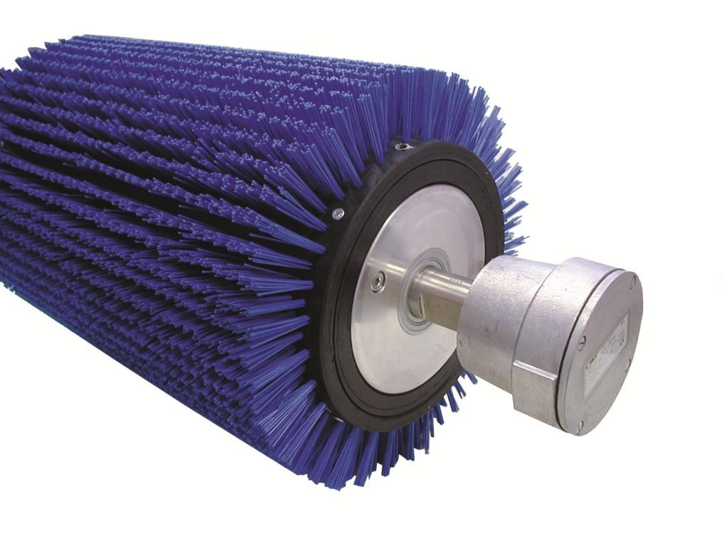
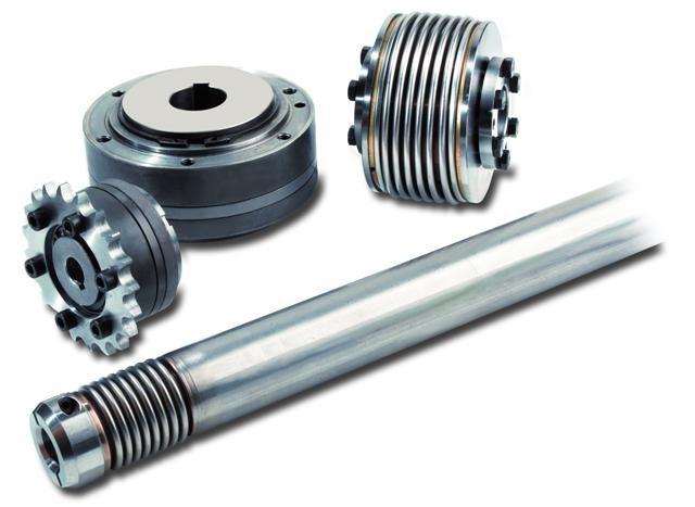
5 The truly flexible alternative to couplings and universal joints and shafts General Product Information Advantages Basic structure Load (Torque) Operating speeds The use of gearing Curves in the shaft Direction of rotation Installation and care of flexible shafts and casings Lubrication of flexible shafts What next? A flexible shaft makes it possible to transmit power between two points regardless of their relative positions. Use flexible shaft to transmit rotary power around a curve! GPI 0303 / 01 1 / 6

6 Advantages Design freedom Design your system and place your driving and driven elements in the preferred position. Design simplicity No need to spend precious time ensuring tight drive system tolerances. Flexible shaft take up large misalignments by design Moving parts Ideal for hand tools or situations which involve constantly changing positions. Dampens vibration Tolerates vibration Reliable Minimum moving parts ensures reliability through simplicity Bi-directional Designed to deal with the most complex design requirements Safe Supplied as a self-contained drive the system is fully contained Simple installation Flexible to allow installation in the smallest of spaces. Basic structure A complete flexible drive will usually be made up of: GPI 0303 / 01 2 / 6
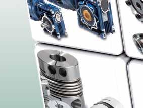
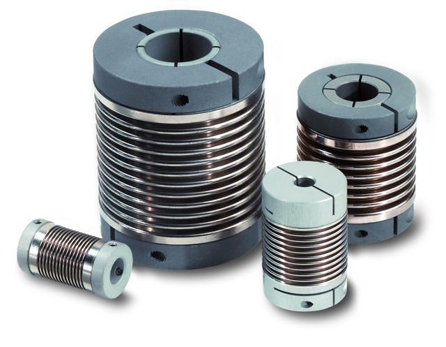
7 A flexible shaft. This is the part that does the work and transmits the rotary motion. A flexible casing. This contains the flexible shaft and prevents excessive twisting under load. End connections. These are usually required to connect to the driving (e.g. motor/hand wheel) and driven (e.g. gearbox, valve) elements of the system. Flexible shaft is built by winding one layer wire over another with a single wire or mandrel in the centre. Successive layers alternate in pitch and direction. Typical combinations are: The shaft only with machined shaft ends attached or a squared formed onto the end of the shaft. The shaft and casing only as above but with the addition of a casing to restrict shaft twisting. A complete flexible drive as described above. MasterFlex and LinkFlex Industrial flexible Industrial shafts incorporate the latest advancements in flexible shaft design and construction and are manufactured using high tensile wires in carbon or stainless steel. The characteristics of a flexible shaft are determined by the combination of the following factors: Grade of wire Number of layers Size of wire Number of wires in each layer Built-in tension Varying the combination of these basic characteristics produces different types of shaft. At one extreme is a shaft with maximum torsional stiffness, or resistance to twisting under load, giving minimum flexibility; at the other extreme is an GPI 0303 / 01 3 / 6
8 exceptionally flexible shaft which low torsional stiffness. Between these extremes are many flexible shafts designed to meet our customer s requirements. Factors that affect the design and application of a flexible shaft are discussed below: Load (Torque) The load to be moved is normally expressed as the torque required to move the load. The torque that a shaft must transmit is the principal factor in shaft selection. The torque requirement should be the maximum anticipated and, where possible, determined by direct measurement. There is a distinct advantage in operating a flexible shaft at the highest speed conditions will permit, as the higher the speed the lower the torque on the shaft. Other factors to consider are starting torque, reversing shocks and fluctuating loads all of which may constitute overloads on the shaft. Where the overload strains on the shaft are not severe the factor of safety will generally be sufficient. Where these factors are substantially more than normal running torque loads then a shaft capable of carrying these loads must be used. Operating speeds Ordinarily, speeds of rpm are recommended as being well suited to flexible shaft operation. Shafts of a larger diameter when run in a curved condition speeds should not exceed 152 surface metres per minute because of the possible excessive heating. This maximum surface speed for any given shaft may be translated in r.p.m. by using the following formula: However, there are many applications where speed exceeds this guide and these figures represent a general rule for obtaining the best service life. The use of gearing It is common practice, where standard motors are used, to introduce gearing to increase or decrease the ultimate speed of the operated device or tool. Bearing in mind the desirability of always running a flexible shaft at the highest practical speed, it follows that in every case where gearing is used it should be located so that the flexible shaft operates at the higher speed. Where gearing is introduced to reduce speed it should be placed at the driven end of the shaft; to increase speed place the gearing at the motor end. GPI 0303 / 01 4 / 6
9 Curves in the shaft Since the flexible shaft was developed primarily as a means of transmitting power under conditions that make it impossible to use a solid shaft, most applications involve curves. These applications may be divided into two types: 1. Those in which the shaft operates in a given position and the curve or curves in the shaft remain fixed. 2. Those in which there are relative movement between the driving and the driven elements, and the curvature of the shaft is continually varied. Each shaft has a recommended minimum operating radius. This is the radius of the smallest curve in which the shaft should be operated. It varies with the type of shaft and the shaft diameter. Figure quoted for MOR includes a suitable safety factor. A shaft should not be bent in a curve of smaller radius than its recommended minimum. The main consideration with respect to curves is their effect on the torque capacity of a shaft and on its service life. The torque capacity and service life of any given flexible shaft decreases as the radius of the curve is reduced. Therefore in working out an application the rule is to design all curves with the largest possible radius the application will permit. Where conditions impose more than one curve in the shaft the radius of the smallest curve should be used as the basis for selecting shaft. Direction of rotation The pitch of the outer layer of wires determines the direction of rotation in which the shaft will give the best results. The shaft should be rotated in the direction that tends to tighten up its outer layer. When the shaft is operated in the opposite direction the torque capacity is generally reduced by 50%. However, this reduction in torque capability is less severe in the range of the bi-directional shafts. Installation and care of flexible shafts and casings 1. Never bend a flexible shaft, or a casing with a shaft inside it, in a radius smaller than the minimum operating radius of the particular shaft. 2. Do not subject the shaft or casing to unnecessary end pull or compression. Excessive tension on shaft or casing may cause permanent damage. 3. When installation is made, check for correct protrusion of shaft fittings to ensure proper engagement with mating parts. 4. After one end of a flexible shaft combination has been attached at the driving or driven end, be sure the shaft rotates freely before attaching the other end. Also, make certain that end fittings are properly engaged at both ends and that the shaft is not cramped in the casing. GPI 0303 / 01 5 / 6
10 5. Keep the flexible shaft and inside of casing free from dirt and grit. 6. Securing the casing with clamps at suitable intervals is desired in all fixed applications. 7. Frequent lubrication of flexible shafts is not always necessary except with large diameter shafts. Steel flexible shafts should always have a thin coating of grease to prevent corrosion. Lubrication of flexible shafts Flexible shafts generally require periodic lubrication. The frequency of lubrication depends on the nature of the service. Where the shaft operates for long periods or is subjected to considerable flexing during operation, the lubrication should be more closely supervised. General lubrication the following procedure is recommended: 1. Remove the shaft from the casing. Clean both the shaft and inside the casing thoroughly by washing in a degreasing agent. 2. Drain the casing and dry the shaft. 3. Coat the entire shaft lightly with a good grade of grease. Contact our service department if you require details of the grease originally used. Grease as the shaft is assembled into the casing. Do not force grease into the casing with grease guns or pressure lubricators. We can also supply a range of stainless steel flexible shafts which require, when used in our new flexible drive systems, no grease. What next? If you are planning to use a flexible shaft in your application or now realize that our flexible shaft will solve your engineering problem then use the technical data of our MasterFlex. These drives are standard products that, if not suitable, can be adapted for your application. If you require a more bespoke solution you can use the performance data quoted for the MasterFlex drives as a guide to typical flexible shaft performance. ACT IN TIME Rue du Valcq, 47 * 1420 Braine-l Alleud * Belgium Tel * Fax * info@actintime.be GPI 0303 / 01 6 / 6

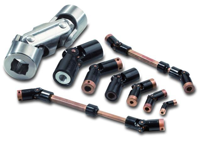
11 LinkFlex Mechanical power transmission made easy Mechanical power transmission made easy for short lengths The truly flexible alternative to couplings and universal joints and shafts ACT IN TIME Rue du Valcq, 47 * 1420 Braine-l Alleud * Belgium Tel * Fax * info@actintime.be
 and a steel shaft.")
12 Please contact our sales department if you require: Higher torque figures than those stated... Longer or shorter couplings... Alternative bore sizes or keyways etc... Couplings in Stailess Steel, Non- Magnetic or Non-Ferrous materials. Standard material for all couplings is steel end connectors (En3b) and a steel shaft. End connectors are fitted with an appropriate steel grub screw. Assembly is blacked to offer corrosion resistance. To order - simply telephone quoting the part number required i.e. LF 03010/030 (/30 = 3.0mm bore) and quantity desired. Preferred sizes of bores are given in the above tables under column 'c'.

13 Tel actintime.be
14 ACT IN TIME MECHANICAL POWER TRANSMISSION MADE EASY NORMAL DUTY (Oilite Bearings - End Type Codes R & S) MasterFlex - Dimensions me.be T All dimensions in mm Shaft Ø Connector Bores (A,B and C) d D E F G Max H J K A B C ,5 10, M15 x , M18 x , M21 x ,5 17, M22 x , ,5 M26.5 x ,5 M29.5 x
15 ACT IN TIME MECHANICAL POWER TRANSMISSION MADE EASY HIGH DUTY Ball Bearing MasterFlex - Dimensions ime.be T Dimension Table for HIGH DUTY (Ball Bearings - End Type Codes M & N) All dimensions in mm TBA means : To Be Advised Shaft Ø Connector Bores (A,B and C) A B C d D E F G Max H J K ,75 10, M18 x , M21 x ,5 19, M27 x ,5 17,5 68, M30 x ,5 22,5 78, M34 x ,5 26, M38 x , , M44 x , M50 x TBA TBA TBA M74 x 2 84

16


17 Aandrijftechniek Uw toepassing Onze oplossing

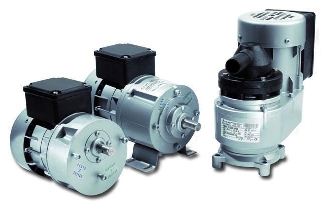

18 DOGA GYROS KELVIN PEEI MOGER SIREM

19 DAVID LAT SIREM
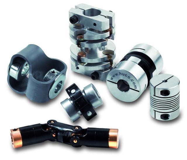
20 ACC&S HAFNER HEYD HUCO
21 LINKFLEX MASTERFLEX


22 FR NL T
Changes in direction.! Using pulleys with belts
 Mechanisms Changes in direction! Using pulleys with belts Changes in direction! Using friction wheels Changes in direction! Using gears Worm drive! Reduces the speed! It is non-reversible Worm drive! Multiple
LESSON Transmission of Power Introduction
 LESSON 3 3.0 Transmission of Power 3.0.1 Introduction Earlier in our previous course units in Agricultural and Biosystems Engineering, we introduced ourselves to the concept of support and process systems
TRANSLATION (OR LINEAR)
") 5) Load Bearing Mechanisms Load bearing mechanisms are the structural backbone of any linear / rotary motion system, and are a critical consideration. This section will introduce most of the more common
5) Load Bearing Mechanisms Load bearing mechanisms are the structural backbone of any linear / rotary motion system, and are a critical consideration. This section will introduce most of the more common
PRECISION BELLOWS COUPLINGS
 PRECISION BELLOWS COUPLINGS Bellows couplings are used where precise rotation, high speeds, and dynamic motion must be transmitted. They exhibit zero backlash and a high level of torsional stiffness, offering
Gearheads H-51. Gearheads for AC Motors H-51
 Technical Reference H-51 for AC Since AC motor gearheads are used continuously, primarily for transmitting power, they are designed with priority on ensuring high permissible torque, long life, noise reduction
Torque Limiter 320 Series Overview. Torque Limiter 320 Series
 Torque Limiter 0 Series Overview Torque Limiter 0 Series Torque Limiter 0 Series For more than 80 years, Autogard products have led the industry in overload protection with high-quality products, design
RE / STAR Tolerance Rings STAR Ball Knobs, Knob and Lever Type Handles
 RE 2 970/.99 STAR Tolerance Rings STAR Ball Knobs, Knob and Lever Type Handles STAR Tolerance Rings Product Overview Tolerance rings are made of hard, embossed spring steel strip and belong to the class
Dr. TRETTER AG. Tolerance Rings. safe cost-effective fast assembly
 Dr. TRETTER AG Tolerance Rings safe cost-effective fast assembly Tolerance Rings are corrugated metal strips manufactured of high quality spring steel. Tolerance Rings are a fastening device between two
Simple Gears and Transmission
 Simple Gears and Transmission Simple Gears and Transmission page: of 4 How can transmissions be designed so that they provide the force, speed and direction required and how efficient will the design be?
Shaft-Hub-Connections
 Stand: 14.01.2010 Shaft-Hub-Connections Shrink Discs Cone Clamping Elements Star Discs 36 Edition 2012/2013 RINGSPANN Eingetragenes Warenzeichen der RINGSPANN GmbH, Bad Homburg Table of Contents Introduction
Introducing Galil's New H-Bot Firmware
 March-16 Introducing Galil's New H-Bot Firmware There are many applications that require movement in planar space, or movement along two perpendicular axes. This two dimensional system can be fitted with
Simple Gears and Transmission
 Simple Gears and Transmission Contents How can transmissions be designed so that they provide the force, speed and direction required and how efficient will the design be? Initial Problem Statement 2 Narrative
SELECTING A BRUSH-COMMUTATED DC MOTOR
 SELECTING A BRUSH-COMMUTATED DC MOTOR BASIC PARAMETERS Permanent magnet direct current (DC) motors convert electrical energy into mechanical energy through the interaction of two magnetic fields. One field
Repeatability. Prototyping. High Precision Lead Screws
 High Repeatability High accuracy Short Lead times Fast Prototyping High Precision Lead Screws Offering smooth, precise, cost effective positioning, lead screws are the ideal solution for your application.
The gear boxes can be run at the same speeds as the actuator models. Do not exceed torque ratings.
 1. What is the lifting torque required? The lifting torque for a single actuator depends on the load, the worm gear ratio, type of screw (machine cut or ball screw) and the pitch of the lifting screw.
Group 078
 1-078-080111 Group 078 EUROTEC TIRE COUPLINGS American Metric s eurotec tire couplings provide all the desirable features of an ideal flexible coupling, including Taper Lock installation. The eurotec tire
LONG LENGTH DESIGN MANUAL CONTENTS PAGE. Introduction Long Length features & benefits... 2 Long Length belting programme... 7
 DESIGN MANUAL LONG CONTENTS PAGE LENGTH Introduction Long Length features & benefits... 2 Long Length belting programme... 7 Drive Design Belt drive selection procedure... 8 Belt pitch selection guides...
Flexible Wellen Flexible Reach Rods. Technical Information. ARMATUREN tramistec is a brand of
 Flexible Wellen Flexible Reach Rods Technical Information tramistec is a brand of Technical Information Contents Flexible Reach Rods page Introduction General 3 Concept Functional Concept 4 Applicability
Introduction. Lubrication Related Failures. Gear Couplings. Failure Analysis All Types (Page 1 of 7)
") All Types (Page 1 of 7) Introduction A gear coupling serves as a mechanical device which connects shafts of two separate machines and accommodates small amounts of shaft misalignment. Commercial gear couplings
All Types (Page 1 of 7) Introduction A gear coupling serves as a mechanical device which connects shafts of two separate machines and accommodates small amounts of shaft misalignment. Commercial gear couplings
Simulating Rotary Draw Bending and Tube Hydroforming
 Abstract: Simulating Rotary Draw Bending and Tube Hydroforming Dilip K Mahanty, Narendran M. Balan Engineering Services Group, Tata Consultancy Services Tube hydroforming is currently an active area of
using Class 2-C (Centralizing) tolerances. Jack lift shaft lead tolerance is approximately 0.004" per foot.
 tolerances. Jack lift shaft lead tolerance is approximately 0.004 per foot.") WORM GEAR JACK MODELS WORM GEAR ACTIONJAC JACKS Jack systems are ruggedly designed and produced in standard models with load handling capacities from 1/4 ton to 100 tons. They may be used individually
WORM GEAR JACK MODELS WORM GEAR ACTIONJAC JACKS Jack systems are ruggedly designed and produced in standard models with load handling capacities from 1/4 ton to 100 tons. They may be used individually
PK couplings. Product description. PK couplings
 Product description The INKOMA-PK coupling is machine component designed to transmit torque between axially parallel, radially offset shafts. The coupling permits both static and dynamic stepless adjustment
Product description. PK couplings
 Product description The INKOMA-PK coupling is machine component designed to transmit torque between axially parallel, radially offset shafts. The coupling permits both static and dynamic stepless adjustment
Installation and Operational Instructions for ROBA -D Couplings Type 91_. _
 Please read the Installation and Operational Instructions carefully and follow them accordingly! Ignoring these Instructions may lead to malfunctions or to coupling failure, resulting in damage to other
Safety Coupling Overview
 Safety Coupling Overview Safety couplings are used to minimize expensive damage when a collision occurs in a high performance servo drive system. When a collision occurs, the safety coupling will stop
Copyright Notice. Small Motor, Gearmotor and Control Handbook Copyright Bodine Electric Company. All rights reserved.
 Copyright Notice Small Motor, Gearmotor and Control Handbook Copyright 1993-2003 Bodine Electric Company. All rights reserved. Unauthorized duplication, distribution, or modification of this publication,
Compact Modules. with ball screw drive and toothed belt drive R310EN 2602 ( ) The Drive & Control Company
 The Drive & Control Company") with ball screw drive and toothed belt drive R310EN 2602 (2007.02) The Drive & Control Company Bosch Rexroth AG Linear Motion and Assembly Technologies Ball Rail Systems Roller Rail Systems Linear Bushings
with ball screw drive and toothed belt drive R310EN 2602 (2007.02) The Drive & Control Company Bosch Rexroth AG Linear Motion and Assembly Technologies Ball Rail Systems Roller Rail Systems Linear Bushings
Comparison Chart. extremely difficult. Finally, separated components can rarely be re-used.
 JAN 2014 Traditional Connections Why Go Keyless Keyed Bushing Systems Both QD and Taper-Lock bushing and weld-on hub systems are popular component mounting technologies. Yet both are ultimately keyed connections
For advanced drive technology CLAMPEX. Shaft-Hub-Connection. KTR Precision Joints CLAMPEX
 technology CLAMPEX Shaft-Hub-Connection CLAMPEX KTR Precision Joints 07 technology Table of contents Page Brief information 09 Selection and calculation -5 CLAMPEX -Selection Shaft diameter = d 0 10 0
High performance metal disk coupling SERVOFLEX SFF (N)
") High performance metal disk coupling SERVOFLEX SFF (N) Best design for the latest servo motor SERVOFLEX for feed shaft which introduce the high precision clamp method Coupling outer diameter, lineup for
High performance metal disk coupling SERVOFLEX SFF (N) Best design for the latest servo motor SERVOFLEX for feed shaft which introduce the high precision clamp method Coupling outer diameter, lineup for
Caring for cables. Types of installation
 Caring for cables Cable carriers guide and protect cables and hoses on moving machinery, and prevent tangling or damage from debris or contact with the machine itself. Proper use of a cable carrier extends
AGN 076 Alternator Bearings
 Application Guidance Notes: Technical Information from Cummins Generator Technologies AGN 076 Alternator Bearings BEARING TYPES In the design of STAMFORD and AvK alternators, the expected types of rotor
Specifications. Trantorque GT CALL FAX
 GT Specifications The following pages contain engineering data and product specifications for GT. For CAD drawings of GT, please click on the part number to download the drawing. All drawings are in AutoCAD
NME-501 : MACHINE DESIGN-I
 Syllabus NME-501 : MACHINE DESIGN-I UNIT I Introduction Definition, Design requirements of machine elements, Design procedure, Standards in design, Selection of preferred sizes, Indian Standards designation
Troubleshooting Power Transmission Couplings
 Troubleshooting Power Transmission Couplings Introduction Power transmission couplings are used to connect two shafts that turn in the same direction on the same centerline. There are three principle types
Installation and Operational Instructions for EAS -Compact overload clutch, Type 49_. 4._ Sizes 4 and 5
 Please read these Operational Instructions carefully and follow them accordingly! Ignoring these Instructions may lead to malfunctions or to clutch failure, resulting in damage to other parts. Contents:
Marine Engineering Exam Resource Review of Couplings
 1. What are rigid couplings used for? Used to join drive shafts together. True alignment and rigidity are required. Example Drive shafts and production lines, bridge cranes, solid shaft that needs to be
Shaft Couplings Flange-Couplings Rigid Shaft Couplings Flexible Couplings
 Shaft Couplings Flange-Couplings Rigid Shaft Couplings Flexible Couplings 44 Edition 2013/2014 RINGSPANN Registered Trademark of RINGSPANN GmbH, Bad Homburg 2 Table of Contents Flange-Couplings Page Flange-Couplings
Installation and Operational Instructions for EAS -smartic synchronous clutch Type 48_. 5._ Sizes 01 2
 Please read these Operational Instructions carefully and follow them accordingly! Ignoring these Instructions may lead to malfunctions or to clutch failure, resulting in damage to other parts. Contents:
AUTOFLEX DISC COUPLINGS
 AUTOFLEX DISC COUPLINGS Contents & Coupling Application Configurations Coupling Type Typical Application Series Page No Introduction - Disc Configuration 2 Coupling Selection 3 & 4 Service Factors High
Candy Coup-Link OVER YEARS OF INNOVATION
 Candy Coup-Link Zero-backlash, flexible-shaft couplings High torque, excellent response Accommodates misalignment and shaft endplay Aluminum and stainless steel options Inch and metric bores available
Product overview. 10 Bosch Rexroth Corporation Compact Modules R310A 2602 ( ) Compact Modules CKK. Compact Modules with ball screw drive (CKK)
 Compact Modules CKK. Compact Modules with ball screw drive (CKK)") 10 Bosch Rexroth Corporation R310A 2602 (2008.09) CKK with ball screw drive (CKK) Product overview are precision, ready-to-install linear motion systems characterized by their high performance and compact
10 Bosch Rexroth Corporation R310A 2602 (2008.09) CKK with ball screw drive (CKK) Product overview are precision, ready-to-install linear motion systems characterized by their high performance and compact
Uniflex-stow remote valve operating systems
 Flexible shaft system 1 INTRODUCTION The purpose is to provide the user with basic information for the specification, installation, operation, maintenance, repair and parts identification of the Uniflex-stow
 DRUM BRAKE RIMS Periodic inspection of drum brake rims is necessary to determine indications of uneven or excessive wear. In general, brake rim failures other that regular wear are caused by brake linings
TORQUE LIMITER SERIES 200
 TORQUE LIMITER SERIES 200 Quality and Autogard are synonymous with overload protection. The company's reputation for high quality products is derived from over 40 years of design innovation and production.
Chapter 11. Keys, Couplings and Seals. Keys. Parallel Keys
 Chapter 11 Keys, Couplings and Seals Material taken for Keys A key is a machinery component that provides a torque transmitting link between two power-transmitting elements. The most common types of keys
Comparison between Fluid Viscous Dampers and Friction Damper Devices. Fluid Viscous Dampers (FVD) Friction Damper Device (FDD) Working principle:
 Friction Damper Device (FDD) Working principle:") Fluid Viscous Dampers (FVD) Working principle: FVD is a central piston strokes through a fluid-filled chamber. As the piston moves it pushes fluid through orifices around and through the piston head. Fluid
Fluid Viscous Dampers (FVD) Working principle: FVD is a central piston strokes through a fluid-filled chamber. As the piston moves it pushes fluid through orifices around and through the piston head. Fluid
Rodless Pneumatic Cylinders Series OSP-P
 Rodless Pneumatic Cylinders Series OSP-P System Concepts & Components... 2-5 Technical Data... 7-9 Dimensions... 10-15 Active rakes... 16-19 Accessories (Mounts & Supports)... 20-29 Ordering Information...30
CH#13 Gears-General. Drive and Driven Gears 3/13/2018
 CH#13 Gears-General A toothed wheel that engages another toothed mechanism in order to change the speed or direction of transmitted motion The gear set transmits rotary motion and force. Gears are used
GatesFacts Technical Information Library Gates Compass Power Transmission CD-ROM version 1.2 The Gates Rubber Company Denver, Colorado USA
 SIZING UP V-RIBBED BELTS Gary Porter Machine Design October 22, 1992 V-ribbed belts offer several advantages to power transmission drive design. Classical V-belts have a profile shaped like a modified
Why Choose Rexnord? 866-REXNORD/ (Within the U.S.) (Outside the U.S.)
 (Outside the U.S.)") 866-REXNORD/866-739-6673 (Within the U.S.) 44-643-366 (Outside the U.S.) www.rexnord.com Why Choose Rexnord? When it comes to providing highly engineered products that improve productivity and efficiency
866-REXNORD/866-739-6673 (Within the U.S.) 44-643-366 (Outside the U.S.) www.rexnord.com Why Choose Rexnord? When it comes to providing highly engineered products that improve productivity and efficiency
Pin-guided clutch with three flyweights
 S-Type Pin-guided clutch with three flyweights Construction and mode of operation 2 5 4 3 3 1 1 5 2 6 4 = Hub = Flyweights = Cylindrical pin = Tension spring = Lining = Clutch drum / Cover disc Low noise
Heavy-Duty Rod Ends - Male with integral spherical plain bearing
 Heavy-Duty Rod Ends - Male with integral spherical plain bearing 65700 Order No. Thread (hand) d 1 l 1 d 2 d 3 d 4 l 2 l 3 X g H7 65700.W0005 Right 5 33 M 5 11,11 18 20 9 14 65700.W0006 Right 6 36 M 6
Standard model for offset drives by chainwheel, sprocket or gear. Chain coupling adaptor for in-line drives, simple & compact
 Type DSF/EX friction torque limiters Friction torque limiters are simple low cost devices that remove shock loads and protect machinery from overload damage. Easy torque setting and wide torque range Bi-directional
Sensor-Bearing Units Steer-By-Wire Modules Mast Height Control units Other sensorized units
 Mechatronics Sensor-Bearing Units... 957 Steer-By-Wire Modules... 967 Mast Height Control units... 969 Other sensorized units... 971 955 Sensor-Bearing Units SKF Sensor-Bearing Units... 958 SKF Explorer
Lectures on mechanics
 Lectures on mechanics (lesson #3) francesco.becchi@telerobot.it LESSONS TIME TABLE (pls. take note) 28/11 h9/12- mech components 1 (3h) 4/12 h9/12 mech components 2 (3h) 11/12 h9/12 mech technologies (3h)
...components in motion. Miniature Linear Guideways
 ...components in motion Miniature Linear Introduction Miniature linear guideway systems are widely used throughout industry for precise, compact applications. Precise and Stainless The gothic arch shape
CLASSIFICATION OF ROLLING-ELEMENT BEARINGS
 CLASSIFICATION OF ROLLING-ELEMENT BEARINGS Ball bearings can operate at higher speed in comparison to roller bearings because they have lower friction. In particular, the balls have less viscous resistance
KTR Torque Limiters Overload Protection Systems
 KT Torque Limiters Overload Protection Systems UFLEX - Friction Disk - Zero Backlash Ball Detent KT SI - Ball/oller Bearing Style KT SI Compact - Zero Backlash Ball Detent Catalog Contents (Metric) Page
Contents. SKF Grid Couplings Selection... 34
 SKF Couplings Contents The SKF brand now stands for more than ever before, and means more to you as a valued customer. While SKF maintains its leadership as a high-quality bearing manufacturer throughout
SCREW JACK POWER TRANSMISSION COMPONENTS TYPICAL SYSTEM ARRANGEMENTS
 TYPICAL SYSTEM ARRANGEMENTS Duff-Norton offers all of the components necessary to complete your power transmission system, whether it consists of a single actuator or a multiple actuator arrangement. We
Magnetic particle clutches and brakes
 Accurate torque control with instantaneous engagement! Warner Electric Precision Tork magnetic particle clutches and brakes are unique because of the wide operating torque range available. Torque to current
Features of the LM Guide
 Features of the Functions Required for Linear Guide Surface Large permissible load Highly rigid in all directions High positioning repeatability Running accuracy can be obtained easily High accuracy can
TYPE TSC/TLC T SERIES FLEXIBLE DISC COUPLINGS
 TYPE TSC/TLC A Stainless steel flexible discs B Overload collars C Cartridge transmission unit D Anti-fly feature E Anti-corrosion treatment F Hubs with API puller holes G Robust hub bolt H Large shaft
Highest Precision: SPL Series
 Highest Precision: SPL Series GAM can. Just ask! If you don t see exactly what you need, let us know. We can modify the SPL Series gearboxes to meet your needs. Page 3 provides a list of commonly requested
T95 Load Cell Assembly for Silo, Tank & Vessel Weighing and Axle Weighing
 T95 Load Cell Assembly for Silo, Tank & Vessel Weighing and Axle Weighing Capacities 2t to 20t Stainless Steel Load Sensor OIML C3 approved Integrated Lift Off Prevention Load cell is always in Tension
WORKHOLDING SYSTEMS
 www.ptgworkholding.co.uk WORKHOLDING SYSTEMS INSTALLATION & PRE-LOADING INSTRUCTIONS INSTALLATION & PRE-LOADING INSTRUCTIONS Pre-load Flats Machine Drawbar M/C Spindle Pre-load Adjustment Screw Mandrel
How New Angular Positioning Sensor Technology Opens A Broad Range of New Applications. WhitePaper
 How New Angular Positioning Sensor Technology Opens A Broad Range of New Applications WhitePaper How New Angular Positioning Sensor Technology Opens A Broad Range of New Applications A new generation of
Ball splines can be configured for an endless number of automated operations. Demystifying Ball Spline Specs
 Ball splines can be configured for an endless number of automated operations. Demystifying Ball Spline Specs Place a recirculating-ball bushing on a shaft and what do you get? Frictionless movement of
Instruction and Installation Manual
 Instruction and Installation Manual ROSTA Tensioner Devices Tensioners Accessories -G -W -R Sprocket wheel N Chain rider P Oil resistant Up to + 120 C Reinforced Sprocket wheel set Chain rider set -I -F
Cross Tensioners. Frames. Bearings. Springs. Mounting Holes. Adjustment Marks
 Cross Tensioners Cross Tensioners provide constant belt or chain tension. Their automatic tensioning action translates into improved performance and extended life for most types of fixed-centre drives.
TORQUE LIMITER SERIES 600. Airjustor
 TORQUE LIMITER SERIES 600 Airjustor Quality and Autogard are synonymous with overload protection. The Company's reputation for high quality products is derived from over 40 years of design, innovation
...our linkages, your solution. Rod Ends
 ...our linkages, your solution Technical Information Introduction All of our rod ends incorporate either a plain spherical bearing, ball bearing, or roller bearing. Below is an overview of each type. Plain
RACK JACK. Synchronous Lifting Systems
 RACK JACK Synchronous Lifting Systems RACK JACK (ROUND RACK TYPE) Operation The Rack Jack from WMH Herion provides simple synchronous lifting motion. The system of rack and pinion transforms linear motion
DESIGN OF MACHINE MEMBERS - I
 R10 Set No: 1 III B.Tech. I Semester Regular and Supplementary Examinations, December - 2013 DESIGN OF MACHINE MEMBERS - I (Mechanical Engineering) Time: 3 Hours Max Marks: 75 Answer any FIVE Questions
Linear Shaft Motors in Parallel Applications
 Linear Shaft Motors in Parallel Applications Nippon Pulse s Linear Shaft Motor (LSM) has been successfully used in parallel motor applications. Parallel applications are ones in which there are two or
Engineering Data Tensioner Arms idler Sprocket Sets Idler Roller Pulley Sets
 CHAIN & PULLEY TENSIONERS Engineering Data Tensioner Arms idler Sprocket Sets Idler Roller Pulley Sets ENGINEERING DATA TENSIONING TECHNOLOGY Chain & V-Belt Tensioning Roller chains are power transmission
DESIGN GUIDE Push-Pull and Pull-Pull Controls Design Guide. Push-Pull Controls. Pull-Pull Controls
 CMA Control Cables DESIGN GUIDE Push-Pull and Pull-Pull Controls Design Guide There are many common, everyday applications that use efficient and reliable CMA controls. These applications include automotive
For advanced drive technology CLAMPEX. Shaft-hub-connection. KTR Precision joints CLAMPEX
 technology CLAMPEX Shaft-hub-connection CLAMPEX KTR Precision joints 227 technology Table of contents Page Brief information 228 Selection and calculation 25-255 CLAMPEX -Selection Shaft diameter = d 0
OVERLOAD CLUTCHES FOR INDEX DRIVES
 The Driving Force in Automation OVERLOAD CLUTCHES FOR INDEX DRIVES WARNING WARNING This is a controlled document. It is your responsibility to deliver this information to the end user of the CAMCO indexer.
Vibration damping precision couplings
 Vibration damping precision couplings In light of the advantages of elasticity, strength, resilience, and damping effects, elastomer materials are now being used in most areas of mechanical engineering.
Why bigger isn t always better: the case for thin section bearings
 White Paper Why bigger isn t always better: the case for thin section bearings Richard Burgess, Les Miller and David VanLangevelde, Kaydon Bearings Typical applications Thin section bearings have proven
ORIGA Pneumatic Linear Drives OSP-L
 ORIGA Pneumatic Linear Drives OSP-L Very long lifetime and lowest leakage A NEW Modular Linear Drive System With this second generation linear drive Parker Origa offers design engineers complete flexibility.
Table of Contents. Standard Taps
 Table of Contents Standard Taps Standard Taps--High Speed Steel Machine Screw Sizes... 3 Standard Taps--High Speed Steel Hand Taps (Fractional Sizes)... 5 Standard Taps--High Speed Steel Machine Screw
The Separator arrangements depend on the application (see order example or separator options).
.") SLE Energy chains individual solutions large dimensions simple handling The order for a steel chain SLE should contain the following data: Type / Radius x Length / Width - Connector Arrangement ; Separator
SLE Energy chains individual solutions large dimensions simple handling The order for a steel chain SLE should contain the following data: Type / Radius x Length / Width - Connector Arrangement ; Separator
Chapter 5 FOUNDATION. 2010, The McGraw-Hill Companies, Inc. 2010, The McGraw-Hill Companies, Inc.
 Chapter 5 FOUNDATION 1 FOUNDATION - A rigid foundation is essential for minimum vibration and proper alignment between motor and load. Concrete makes the best foundation, particularly for large motors
Shrink Discs, Smart-Lock & Shaft Couplings
 RINGFEDER Products are available from MARYLAND METRICS Shrink Discs, Smart-Lock & Shaft Couplings US 08 2009 Partner for performance RINGFEDER Products are available from MARYLAND METRICS P.O. Box 261
DESIGN OF MACHINE ELEMENTS UNIVERSITY QUESTION BANK WITH ANSWERS. Unit 1 STEADY STRESSES AND VARIABLE STRESSES IN MACHINE MEMBERS
 DESIGN OF MACHINE ELEMENTS UNIVERSITY QUESTION BANK WITH ANSWERS Unit 1 STEADY STRESSES AND VARIABLE STRESSES IN MACHINE MEMBERS 1.Define factor of safety. Factor of safety (FOS) is defined as the ratio
Standard model for offset drives by chainwheel, sprocket or gear. Chain coupling adaptor for in-line drives, simple & compact
 Type DSF/EX friction torque limiters Friction torque limiters are simple low cost devices that remove shock loads and protect machinery from overload damage. Easy torque setting and wide torque range Bi-directional
Coupling Options for Every Application
 Coupling Options for Every Application Bellows Couplings High torsional rigidity, low inertia, zero backlash and misalignment compensation Can be used at temperatures up to 570 F without any limitations
Features of the LM Guide
 Features of the Functions Required for Linear Guide Surface Large permissible load Highly rigid in all directions High positioning repeatability Running accuracy can be obtained easily High accuracy can
lea) shows a compression type. These couplings are used for
 shows a compression type. These couplings are used for") Mechanical Equipment - Course 230.1 SHAFT COUPLINGS Couplings Couplings are used to join two shafts provide some means of transmitting power source to a driven member. There are two tiona of couplings,
Mechanical Equipment - Course 230.1 SHAFT COUPLINGS Couplings Couplings are used to join two shafts provide some means of transmitting power source to a driven member. There are two tiona of couplings,
Circular Motion. Save My Exams! The Home of Revision GCSE(9-1) Level. Edexcel Topic. Exam Board. Circular Motion Sub-Topic Booklet Mark Scheme 1
 Level. Edexcel Topic. Exam Board. Circular Motion Sub-Topic Booklet Mark Scheme 1") Circular Motion Mark Scheme Level GCSE(9-) Subject Physics Exam Board Edexcel Topic Circular Motion Sub-Topic Booklet Mark Scheme Time Allowed: 62 minutes Score: /62 Percentage: /00 Page M.(a) A (b) (i)
Circular Motion Mark Scheme Level GCSE(9-) Subject Physics Exam Board Edexcel Topic Circular Motion Sub-Topic Booklet Mark Scheme Time Allowed: 62 minutes Score: /62 Percentage: /00 Page M.(a) A (b) (i)
ACCOUNTING FOR LOST MOTION
 Backlash and deflection are critical factors when designing mechanical control cables. Mechanical control cables provide a simple, lightweight, economical, and reliable way to activate throttles, latches,
I-BEAM 348 and 458 Overhead Heavy Duty Monorail Conveyor
 I-BEAM 348 and 458 Overhead Heavy Duty Monorail Conveyor Standard Conveyor 2 3/8" 1" Ø11/16" 4" 8" 41 Standard Conveyor I-BEAM TRACK & CHAIN 3" & 4" I-BEAM TRACK Hi-Carbon Steel Track The Richards-Wilcox
ENGINEERED SOLUTIONS Based on Reali-Slim Bearings A N I L L U S T R A T E D M O U N T I N G G U I D E
 ENGINEERED SOLUTIONS Based on Reali-Slim Bearings A N I L L U S T R A T E D M O U N T I N G G U I D E Reali-Slim thin-section bearings have contributed to reductions in weight and size in thousands of
How to Build with the Mindstorm Kit
 How to Build with the Mindstorm Kit There are many resources available Constructopedias Example Robots YouTube Etc. The best way to learn, is to do Remember rule #1: don't be afraid to fail New Rule: don't
DECOILING STRAIGHTENING FEEDING ACCUMULATING REWINDING TRAVERSING
 DECOILING STRAIGHTENING FEEDING ACCUMULATING REWINDING TRAVERSING CONSULTANCY, DESIGN, PRODUCTION, AFTER-SALES SERVICE CONTENT 03 Consultancy, design, production, after-sales service 04 Strip decoiling,
Standard with cone bushing. Backlash-free Safety Clutch
 EAS -Compact ratchetting clutch/synchronous clutch The Backlash-free Safety Clutch for Standard with cone bushing Packaging Machinery Machine Tools Paper Machinery Indexing Drives Servo Motors EAS -NC
Seagull Solutions, Inc.
 March 2002 Seagull Solutions, Inc. 16100 Caputo Drive Morgan Hill, CA 95037 Phone: 408-778-1127 Fax: 408-779-2806 www.seagullsolutions.net Report By: Donald L. Ekhoff ekhoff@seagullsolutions.net & Peter