Low-Medium Power CATALOGUE 08/09 CG08Z/GB. Zucchini SpA
|
|
|
- Merry Cook
- 5 years ago
- Views:
Transcription
1 Zucchini SpA Via Conicchio, Brescia - Italy Tel Fax info@zucchinispa.it LOW-MEDIUM POWER CATALOGUE 08/09 Low-Medium Power This catalogue replace CATLPMP-E. Zucchini S.p.A. reserves at any time the right to modify the contents of this booklet and to communicate, in any form and modality, the changes brought to the same. CG08Z/GB
2


3 EB EASYBAR 25-40A page 1 LOW POWER LB LIGHTING BUSWAY HL HIGH LIGHTING 25-40A 25-40A page 17 page 37 SL SERIE LUCE 40-63A page 59 MEDIUM POWER MS MINI SBARRA MR MEDIUM RATING TS TROLLEY SYSTEM A A A page 73 page 89 page 125 HIGH POWER SCP SUPER COMPACT HR HIGH RATING CRT CAST RESIN TRANSFORMERS A A kVA page 143 page 151 page 157 TECHNICAL INFORMATION page 165


4 Integrated solutions for global projects Legrand is the world specialist in products and systems for electrical installations and information networks: - Distribution, automation panels and protection equipment - Cable management (trunking, cable trays and wire mesh) - Cast resin transformers - Busbars and lighting busbars Every product and system needed for distributing energy and protecting people and property. Altis TM industrial cabinets Atlantic and Marina boxes Cablofil cable trays 2 BUSBAR


5 DMX, DPX, DX circuit breakers XL 3 distribution tib ti cabinets Zucchini busbars In a context of accelerated globalization and increasingly complex projects, the support of a reliable and competent partner is absolutely essential, a real key to the success of your company. Choosing the Legrand Group means the assurance of benefiting from global expertise throughout the world thanks to its strong local presence. A vast choice of carefully styled products compose solutions which in turn form coherent systems incorporating the latest technological innovations. Choosing Legrand also means you are sure to be assisted by professionals at your service any time, from your project s design through to its completion. EdM cast resin transformers GENERAL FEATURES LOW-MEDIUM POWER GENERAL CATALOGUE 3

 backbones of buildings used for the commercial-service sectors, thus observing the time required for the installation and")
6 Basic concepts for busbars The busbar is the most modern solution for the distribution of energy in an installation for machinery, equipment and lighting fittings, in all types of buildings such as warehouses, trade fairs, or any place where the pace of installation operations provide tangible benefits immediately, but also continue to cumulate benefits at every maintenance intervention or modification. The busbar is also frequently used to power the (horizontal and vertical) backbones of buildings used for the commercial-service sectors, thus observing the time required for the installation and providing a final solution with remarkable technical advantages compared to an equivalent traditional system made with cables. Zucchini s busbars, available in 3 segmented ranges (Low Power, Medium Power and High Power), are able to meet all installation requirements, from 25A to over 5000A. BUSBAR

7 EASY TO DESIGN The electric design of the busbars is achieved by Zucchini in compliance with the product Standards. The rated current of our busbars is guaranteed at a room temperature of 40 C (n.d.r. the Standard requires 35 C). After choosing the busbar which is able to meet the operating current regulations, it will be very easy to verify the voltage drop as well as the protection against overcurrents by using the technical tables available for all our production lines. In particular, these tables define: the short circuit and peak currents that can be supported by the busbar waiting for the protection device located upstream to start operating, the specific voltage drop based on the average cos phi of the loads, the losses and other data (R, X, Rpe, etc.) which allow the planning engineer to carry out calculations with electric values, which are not estimated but the result of measurements made during heating and short circuit tests (in certified LOVAG laboratories), which have certified all our product lines. When using busbars, the load protection is located very close to the device (decentralized protection); junction boxes can contain protection devices such as thermal magnetic circuit breakers, fuse carriers and motorized switches which allow you to easily and efficaciously manage the system. Example of an elctric characteristics table INTRINSIC SAFETY A busbar does not use large amounts of insulating plastic material and potentially dangerous materials in case of fire. Furthermore, the plastic materials used for the insulating parts of the busbars are always self-extinguishing (from V0 to V2) and the gas emission is generally very low (Halogen Free). Low electromagnetic emission is another advantage of the busbars compared to that of an equivalent cable system: as a result, the metal plate casing of the busbars serves as a screen for the electric field (shielded enclosure); the extreme vicinity between the phase conductors also reduces the emission of the magnetic field considerably. The Italian law, according to the DPCM (Prime Ministerial Decree) of July 8th 2003, sets the target level to 10 µt and the quality level limit to 3 µt. The tests carried out on one of our 2500A SCP busbars at full operating current has shown that the emission of the magnetic field (magnetic induction) is lower than the target level of the Decree at a distance of 0.3m, whereas the threshold considered as the quality target can be achieved at a distance of only 0.7m from the busbar. These features make our busbars the unavoidable choice for hospital facilities, data processing centres and wherever it is necessary to supply a large amount of power in the vicinity of workplaces and/or sensitive equipment.. Zucchini busbar electromagnetic emission. GENERAL FEATURES LOW-MEDIUM CATALOGO POWER GENERAL CONDOTTI CATALOGUE SBARRE 5
8 Basic concepts for busbars FLEXIBILITY By using the outlet windows located on the straight elements, the busbars provide high management flexibility, both when planning (electrical engineer) and when installing the system (installer); they are also used for the unavoidable changes required by the electric system to adapt to the varied needs of the end user. The junction boxes can be inserted and removed from their windows when the busbar is electrically powered and inserted in another junction window, thus avoiding downtime. The engineering department in charge of designing the busbar does not have to know the exact position of the machinery and of the electric loads that will be installed in the company; the project that will be carried out will be open to changes and variations which will be defined by the end user when operationally using the system. No more point-point connections but only one power distribution system to which you will always be able to connect to wherever there is a free window. Because of its flexibility and durability features Zucchini s busbar, installed inside a building, allows you to easily change the destination of its intended use of the rooms, thus giving also advantages to those who manage and locate the various parts of the building premises. Busbar system Cable and tube lighting system BUSBAR
9 QUICK INSTALLATION Zucchini s junction and fixing systems have been designed and created to install busbars easily. In a cable and tray system, the time required to install only the tray is the same used to install a complete system in busbars. Furthermore, given the same capacity, a power busbar, which generally has aluminium conductors, is much lighter than a system made with (copper) trays and cables: lighter weights require a lower number of supporting frames or, in any case, more simple and inexpensive supporting frames. That is why the installation time of a busbar is obviously shorter than a similar system made with cables. REDUCED DIMENSIONS The overall dimensions of the busbars are generally smaller than an equivalent system made with cables, especially when the currents to be carried exceed 1000A and when several cables in parallel are necessary to ensure such capacity. Other advantages can be achieved when there are changes of direction where the radius of curvature of the cables is minimal and enough to not damage the insulating material; busbars allow you to change directions with 90 angles, thus optimizing the small spaces used in service areas. GENERAL FEATURES LOW-MEDIUM POWER GENERAL CATALOGUE CATALOGO CONDOTTI SBARRE

10 EB - EASYBAR 25-40A THE NEWS A lot of energy in little space


11 EB EASYBAR SECTION CONTENTS 2 General features 4 Advantages 8 The EASYBAR range 10 Straight elements and tap-off plugs 11 Installation accessories 12 General rules for installation 166 Technical information 174 Determination of the operating current of a busbar 1 LOW-MEDIUM POWER GENERAL CATALOGUE


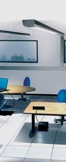
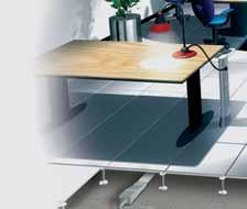
12 The innovative system for the distribution of energy EASYBAR is the perfect solution for the distribution of energy within any service and industrial sector. Its maximum height of only 50mm, the thinnest on the market, makes it an exclusive and innovative product. With EASYBAR, it is possible to distribute 25A or 40A currents, maintaining an IP55 degree of protection when the installation is complete. The elements are available in 2m and 3m lengths. EASYBAR can be positioned: under the raised floor On the wall to outfit work stations in the interspaces of the dry wall plasterboard in the false ceiling 2 EB - EASYBAR


13 EB EASYBAR FLOOR INSTALLATION EASYBAR busbars, because of its reduced 50mm height (with accessories installed), can be positioned in particularly low raised floors. It is suitable for new installations as well as for renovations in which it is not possible to raise the floor. By using tap-off plugs, which can be positioned anywhere on the trunking, it is also possible to connect Legrand fastconnection installation system products such as floor boxes, mini columns and multiple outlet extensions, which can be combined with the Cablofil type wire mesh cable trays system used for the data network distribution and safety circuits. CEILING INSTALLATION Thank to the innovative tap-off plugs, EASYBAR is well suited for distribution of energy for lighting in false ceilings. Specific tap-offs for each phase allow to distribute an even load and quickly connect the lighting fixtures. GENERAL FEATURES LOW-MEDIUM POWER GENERAL CATALOGUE CATALOGO CONDOTTI SBARRE 3


14 Advantages The EASYBAR system has been studied to make installation operations easier and quicker. When using EASYBAR, unlike a traditional energy distribution with trunking lines and cables, the installation time can be reduced by using the snap-on components and through the possibility of creating the lines in 2 ways: 1 - by first positioning the fixing clamping brackets onto the mounting surface, and then clipping in the straight element. With this installation method, all brackets need to be put in the line roughly or with laser tools 2 - by positioning the brackets onto the busbars and then fixing the product. The side fastening system gives you the advantage of having the brackets already aligned by the straight element. MAX. 50 mm ENERGY TAP-OFF WHEREVER YOU NEED IT The tap-off plugs have been designed to be positioned at any point on the busbar for complete modularity REDUCED DIMENSIONS One of the main advantages of this innovative system is its size: the height of the busbars is 17mm Maximum height with the components mounted is 50mm. IP55 PROTECTION The degree of protection of the whole EASYBAR system is IP55 after completing the installation, but thanks to the innovative design, even during installation, if an end cover, joint or covering fiim is missing, an IP2X protection is always guaranteed against direct contact. 4 EB - EASYBAR


15 EB EASYBAR UP TO 7 TAP-OFFS PER METRE Possibility to install up to 7 tap-off plugs per metre, thus allowing a complete utilisation as well as a widespread distribution of energy for different configurations. EASY AND QUICK INSTALLATION The snap-on system reduces the installation time considerably. CONVENIENT IN EVERY WAY Only one element and few installation accessories that guarantee an easy, fast and inexpensive distribution of energy. RESISTANCE AND SAFETY EASYBAR is particularly resistant; in fact the straight elements can be stepped on without damaging them. EASYBAR gives you the possibility of a good, safe installation when worksite jobs are being started. With the safety lock system, even under load, a worker can isolate a line to work in complete security. Thus even during installation or modifications, potential accidents are avoided with EASYBAR. GENERAL FEATURES LOW-MEDIUM POWER GENERAL CATALOGUE CATALOGO CONDOTTI SBARRE 5
16 Installation SOLUTION: traditional or EASYBAR? A traditional energy distribution system requires the use of trunking systems as well as multiple cables. There are various installation operations which are carried at different times, thus prolonging the installation and testing time and hence with increases in cost. By using the innovative EASYBAR system, the installation time is greatly reduced, thus facilitating reliable project management and planning. Furthermore, EASYBAR is easily integrated both with the Cablofil cable tray system and with Legrand products for distribution in offices and all commercial applications. The busbar can be simply clipped onto the same wire mesh cable tray used for the data VDI structured cabling system. The worksite is a extremely severe environment during the installation stage, with all trades coming and going continuously, so EASYBAR was conceived as a very resistant product: it can even be stepped on, allowing the installation without waiting for the floor this factor shall be taken into consideration as many types of underfloor trunking systems do not have this level of robustness. The following table illustrates the cost effective solution of EASTBAR compared to traditional distribution. INSTALLATION STAGES Description Traditional EASYBAR The advantages of using EASYBAR System planning No It is not necessary to know in advance how many work stations there will be Derivation points No If it is necessary to add new stations, all you need to do is install the tap-off plugs on the straight element Material order Limited only to the straight elements, plugs, brackets and to the power lock Trunking installation No The snap-on system allows busbar ducts to be installed easily and quickly Wiring devices No No need for derivation boxes and terminal strips to be cabled each time, just plug in where the derivation is needed Cable insertion No When using Legrand fast connection plugs it is possible to connect EASYBAR tap-off plugs to the Legrand Fast Connection distribution system easily and quickly System testing There is no risk of having disconnections due to cable failure Flexibility No Possibility of being stepped on No EASYBAR can be stepped on and has a degree of protection IP55 after completing the installation 6 EB - EASYBAR


17 EB EASYBAR TRADITIONAL SOLUTION - complex - little flexibility - long installation time requirements EASYBAR SOLUTION - neat - fast - flexible and integrated Integration with the Cablofil wire cable tray GENERAL FEATURES LOW-MEDIUM POWER GENERAL CATALOGUE CATALOGO CONDOTTI SBARRE 7


18 The EASYBAR range STRAIGHT ELEMENTS Straight elements are available with four 25A or 40A conductors with lengths of 3m, 2m and a 1.8m length which can be cut to measure at the worksite. The main features are: derivation from any point of the straight element structure made of galvanized steel degree of protection IP55, for the completed installation TAP-OFF PLUGS Tap-off are used for distributing energy in different points and are available with 10A or 16A rated currents, with or without fuse. The main features are: default phase selection or three-phase version plugs made of self-extinguishing-insulation material plugs that can be installed at any point of the straight element snap-on connection large available surface for clear identification marking FEED UNIT Once wired from the main power network, the feed unit is snapped into place onto the EASYBAR element without using any tools. 8 EB - EASYBAR


19 EB EASYBAR FLEXIBLE JOINT The flexible joint is used to connect two busbar ducts with a bending angle of up to 180. The flexible joint is also useful for changing levels between ducts. END COVER The end cover ensures the IP55 protection degree at the end of the line. SAFETY BLOCK To ensure maximum safety, the optional safety block maintains the plug in the open position and prevents unintentional closure. This safety device can be installed very easily when the plug is open and can be guaranteed by means of a padlock to ensure the safest possible conditions to carry out safely all maintenance operations of the connected loads. GENERAL FEATURES LOW-MEDIUM POWER GENERAL CATALOGUE CATALOGO CONDOTTI SBARRE 9
.")
20 Straight elements and tap-off plugs 25A AND 40A STRAIGHT ELEMENTS Straight elements with 4 copper conductors (3P+N). Supplied with a pre-cut, modular cover and a joining module (for clipping two straight lengths together). IP55 Item Description A - 3 m A - 2 m A - 3 m A - 2 m 10A SINGLE-PHASE TAP-OFF PLUGS WITH A 1 m CABLE Single-phase tap-off plugs without fuse protection with self-extinguishing insulating body, 3 X 1.5 mm 2 cable. IP55 Item Description L1+N L2+N L3+N L2+N2 Single-phase tap-off plugs protected with a 6.3A ø5x20 mm fuse with selfextinguishing insulating body, 3 X 1.5 mm 2 cable. IP55 Item Description L1+N L2+N L3+N L2+N2 16 A SINGLE-PHASE TAP-OFF PLUGS WITH A 3 m CABLE Single-phase tap-off plugs without fuse protection with self-extinguishing insulating body. IP55 Item Description L1+N L2+N L3+N L2+N2 Single-phase tap-off plugs supplied with a ø8.5x31.5 fuse carrier with selfextinguishing insulating body. IP55 Item Description L1+N L2+N L3+N L2+N2 16 A SINGLE-PHASE TAP-OFF PLUGS WITH A 5 m CABLE Single-phase tap-off plugs supplied with a ø8.5x31.5 mm fuse carrier with self-extinguishing insulating body. IP55 Item Description L1+N L2+N L3+N L2+N2 16 A THREE-PHASE TAP-OFF PLUGS WITH A 3 m CABLE Three-phase tap-off plugs without fuse protection with self-extinguishing insulating body. IP55 Item Description L1+L2+L3+N (5x2.5mm 2 ) 10 EB - EASYBAR
21 EB EASYBAR Installation accessories FEED UNIT WITH END COVER Feed unit with closing cap for 25/40A busbars. For special applications, the End Line feed unit can be used: when power feed is needed at both ends of a run, or whenever installation layout demands feed at opposite end. Foolproof mounting to avoid errors. IP55 Item Description Standard feed unit for 25/40A busbars End line feed unit for 25/40A busbars. for special applications FLEXIBLE JOINT Item Description fl exible joint for 25/40A busbar with radius of action up to 180 for connecting 2 straight elements MODULAR COVERS Item Description box with fi ve 0.6 m covers and 10 individual blanking plates. - The 0.6 metre covers have pre-cut modules which allow you to install plugs at any place without removing the whole cover. Snapon installation - the 10 individual blanking plates allow to recreate the IP55 protection degree if the tap-off plugs are removed CLAMPING BRACKETS Brackets for fastening the straight elements in raised fl oors or in false ceilings. Can also be used to attach other material to the busbar Item Description clamping bracket with centre installation hole clamping bracket with side installation hole SAFETY BLOCK Item Description safety block to prevent unauthorised personnel from tampering with open plugs ø6mm padlock CUT TO MEASURE ELEMENT Item Description straight element that can be cut on the jobsite, possibility to cut every 20 cm 1.8 m in length including an additional accessory for resetting the correct insulation between components. CATALOGUE LOW-MEDIUM POWER GENERAL CATALOGUE CATALOGO CONDOTTI SBARRE 11

22 GENERAL RULES FOR INSTALLATION The EASYBAR system is very easy and fast to install. In fact with few operations and with all the snap-on accessories it is possible to create a complete floor, ceiling and wall energy distribution system. The following pages describe the basic operations for the installation of the busbar and for the distribution of energy in different points. Remember that the EASYBAR distribution system is part of the Legrand solution for the workstations: It is the integrated electrical backbone for the DLP columns, mini-columns and floor boxes alongside the Cablofil cable trays for the VDI structured cabling system. Remember that the maximum height of 50 mm (elements and plugs/feed units installed) allows EASYBAR to be used in even the most restrictive modern day installations. INSTALLATION OF THE BUSBARS For the electrical distribution, there is no need to follow the office layout of the furniture. Generally speaking, in order to guarantee the most complete and flexible distribution system under the raised floor or on the ceiling, parallel backbone distribution runs are used. The creation of an EASYBAR layout can be carried out with two methods, making use of two fixing brackets (item and item ): the first method (traditional) is to make use of the fixing bracket item where elements are placed on the floor, without the busbar, and set in line with laser indicators. The busbar will then be positioned accordingly. This is the most classical solution but it is also the most difficult because the installation needs to be carried out in two steps (figure 1), the second (the fastest) method can be carried out in one step, that is to make use of fixing brackets item This accessory is first installed directly on the busbar and then positioned on the floor so that it can be fastened. This solution is possible because the bracket is fastened on one side, hence the hole is not obstructed by the busbar. By making use of this solution, the installation time will be reduced. The busbar will help you to line up all fixing brackets in line (see figure 2). Figure 1 CLACK Figure 2 12 EB - EASYBAR


 by rotating the 2 side screws by 90 2.")
23 EB EASYBAR FEED UNIT The feed units item and item can be wired in a few steps: 1. open the feed unit and wire the cables coming from the main line to the busbar by making use font 2. close the feed unit 3. slide it directly onto the straight element until it automatically clicks into place. 4. remove by a 90 rotation of the 2 screws located on the side of the feed unit and pull off. Cable wiring Power lock installation CLACK FLEXIBLE JOINT CONNECTION In order to make bends, it is necessary to use a flexible joint item The installation of this accessory is very simple and can be carried out in a few steps: 1. remove the joining module from the straight element (if installed) by rotating the 2 side screws by slide the joint onto the busbar until locked into place GENERAL RULES GENERAL FOR INSTALLATION FEATURES LOW-MEDIUM POWER GENERAL CATALOGUE 13
 close the plug to the ON position to make the connection In order to ensure balanced phase distribution, there are also plugs available with a")

24 GENERAL RULES FOR INSTALLATION TAP-OFF PLUG INSTALLATION The installation of the tap-off plug is carried out as follows: set the plug to OFF position (open) snap the plug onto the busbar by placing it on the correct side (foolproof positioning) close the plug to the ON position to make the connection In order to ensure balanced phase distribution, there are also plugs available with a phase-differentiated connection; furthermore, there is an accessory which allows you to prevent unauthorised personnel from unintentionally inserting plugs. This accessory item , combined with the padlock item is positioned on the plug and prevents it from closing. After completing the whole installation and after positioning the various covers, it is possible to change the position of the tap-off plugs whilst keeping the IP55 degree of protection. It is possible to carry out this operation with simple operations: 1. set the plug to OFF position 2. remove the plug from the busbar 3. replace the outlet cover (included in the package of covers item ) with the plug; this will reset the IP55 degree 4. re-position the plug in the required position of the busbar. The dimensions of a plug are the same as the knockouts of the cover. Plug installation CLACK Electrical connection CLACK USING THE CUT TO MEASURE ELEMENT This element is used when it is necessary to have elements cut to size to complete the installation. It is possible to cut this element every 20 cm; its maximum length is 1.8 m. END COVER The end cover are used to complete the installation and to guarantee an IP55 degree of protection. They are supplied with the feed units. End cover installation CLACK 14 EB - EASYBAR


25 EB EASYBAR SYSTEM INTEGRATION EASYBAR can be combined easily and quickly with the Legrand group cable management systems. Thanks to this integration it is possible to create a complete energy distribution system alongside the VDI structured cabling system with only one installation solution. The integration between the systems occurs as follows: the energy distribution occurs through EASYBAR, which can be fixed to the Cablofil wire cable tray trunking system with simple brackets. In this way, it is possible to distribute the data network inside the tray trunking system. The connection to the workstation is achieved through the Legrand system products: from the EASYBAR tap-off plugs the energy is available wherever it is needed the Legrand quick-connection plugs connect the output tap-off plug cable to the fast connection junction boxes. the floor boxes provides local acces for power and data to the workstations distribute the power through the DLP columns and mini-columns Whatever the need, all Legrand group products are integrated into one system for unlimited solutions to manage power and data. EASYBAR installation on Cablofi l wire cable tray GENERAL RULES GENERAL FOR INSTALLATION FEATURES LOW-MEDIUM POWER GENERAL CATALOGUE 15
26 16 LB - LIGHTING BUSWAY 25-40A

27 LB LIGHTING BUSWAY SECTION CONTENTS 18 General features 24 Trunking components: 2 and 4 conductors elements 28 Trunking components: 6 conductors elements 30 Plugs 33 Fixing supports 35 Cable channel and accessories 167 Technical information 174 Determination of the operating current of a busbar 17 LOW-MEDIUM POWER GENERAL CATALOGUE


28 LB Lighting Busway GENERAL FEATURES Zucchini s LB product line is the ideal solution for supplying power to light fixtures for commercial and industrial applications. The main features of the LB range are: speed, simplicity and flexibility when planning and installing the lines; capable of being installed both in false ceilings and below floating floors, because of the IP55 degree of protection; compliance with Standard IEC and 2; rated at average room temperature of 40 C for a higher performance level compared to the 35 C rating required by the standard. Straight element Clamping bracket Tap-off plugs End feed unit Shopping centres Offices 18 LB - LIGHTING BUSWAY
; casing thickness 0.")

29 LB LIGHTING BUSWAY STRAIGHT ELEMENTS The components and the features of the LB straight elements are: a closed and rib-shaped section casing, made with hot galvanized steel (Senzimir) (due to its cross-section and electrical continuity, it also serves as a protective conductor); casing thickness 0.6 mm; reduced dimensions 26x41 mm; painted or with an anodized aluminium casing versions available on request; number of conductors: 2, 4 or 6 rigid copper conductors with a 99.9% purity; conductor section: 3.14 mm 2 for 25A and 6.15 mm 2 for 40A; separation between the conductors by using a V0 (according to UL94) self-extinguishing insulating plastic sheathe and in compliance with the glow-wire test according to IEC ; tap-off outlets equidistant every 1m (3 outlets every 3m) or 0.5m (6 outlets every 3m), receiving the corresponding tap-off plugs (in the LB 6 conductor version the outlets are arranged on both sides of the busbar: 3+3 or 6+6 outlets); a junction block automatically ensuring electrical continuity. The connection between two straight elements is quick; with one operation the mechanical and the electrical connection is ensured between two joined elements; at the same time, an IP55 degree of protection is guaranteed without using additional accessories. The continuity of the protective conductor (casing) is guaranteed by tightening the special connection screw. The whole busbar is fire retardant in compliance with the IEC standard. Store house Hospitals GENERAL FEATURES LOW-MEDIUM POWER GENERAL CATALOGUE CATALOGO CONDOTTI SBARRE 19


30 LB Lighting Busway FEED UNITS Allows you to electrically power the LB line through a cable line; the installation is carried out with a quick junction connection as with the straight elements. The feed units have terminals for the connection of flexible copper cables for sections of up to 25 mm2. There is an anti-pullout cable clamp inside the feed unit. The entrance point for the incoming cable is positioned on the end of the feed unit. Standard end feed unit END COVER The end cover ensures the IP55 protection degree at the end of the line. End cover FIXING DEVICES Specific accessories are available for attaching the busbar to the structure of the building (directly or with a steel chain or cable). The accessories for overhead fixing are: snap clamp: the snap-on installation is extremely fast. This bracket is suitable both for overhanging the busbar to the ceiling and for hanging products such as fluorescent lamps, tap-off boxes, etc., to the busbar itself; snap clamp with ring or hook: the ring or the hook enables to hang lamps easily. simple bracket: used with the ceiling bracket holder, it enables the installation the busbar directly onto the ceiling at a distance of about 25cm; wall bracket: enables the fixing of the busbar directly onto the wall of a building, setting it at the required distance enabling the installation of the necessary components. Fixing accessories for fastening the busbar run to the structure and hanging the lamps onto the busbar 20 LB - LIGHTING BUSWAY
31 LB LIGHTING BUSWAY TAP-OFF PLUGS Used for connecting and energizing light fixtures; their features include: can be inserted and removed when the busbar is energized and when the fixure is under load; the PE contact (Protective Earth) is the first to make an electrical connection when inserting the plug into the outlet and it is the last to disconnect when pulling it out; compliance with all insulating plastic components according to the glow-wire test (IEC ) with V1 self-extinguishing degree (UL94); standard IP55 degree of protection without using additional accessories according to Standard IEC The tap-off plugs are common for the LB 2, 4 and 6 conductors offer. These include: a) 10A pre-wired, pre-positionned phase tap-off plugs with 1m, 3m or 5m of 3x1.5mm 2 cable; b) 16A phase selection tap-off plugs, with terminals for connecting L+N+PE cable; c) 16A phase selection tap-off plugs, with ø5x20mm cylindrical ceramic fuse and with terminals for connecting L+N+PE cable; d) 16A three-phase tap-off plugs, with a set of three cylindrical fuse carriers with terminals for connecting a 3L+N+PE cable. In the LB 6 conductor line, the plugs are polarized, in other words the plug which is installed on one side of the busbar cannot be installed on the other side due to a mechanical lock on the outlet. Phase selection plug Single-phase plugs with 1, 3, 5 m cable GENERAL FEATURES LOW-MEDIUM POWER GENERAL CATALOGUE CATALOGO CONDOTTI SBARRE 21
32 LB Lighting Busway TRUNKING ELEMENTS AND ADDITIONAL ELEMENTS Depending on the different installation requirements Zucchini can provide various technical solutions: a) flexible joint: used to make changes of direction or to avoid possible interferences that may be found on the natural path of the BUSBAR. The features are as follows: same connection method as the straight elements; electrical and mechanical connection with one operation; standard degree of protection: IP55; continuity of the protective conductor, made from the casing of the element itself, guaranteed by tightening the special connection screw; b) cable trunking with cover: this accessory, which can be positioned in the upper part of the busbar, can be used to distribute auxiliary circuits, it is an integral part of the busbar run using special spacers and brackets which support the busbar trunking system firmly. The trunking part is 3 m long and its dimensions are 28x28 mm; c) intermediate feed unit: it can power the busbar from an intermediate point of the line, thus reducing the voltage drop at the end of the line and/or making the installation easier when the electric energy supply point is near the middle of the line. Phase selection tap-off plugs available Wall suspension bracket Ring for suspending a lamp or for suspending other accessories of the busbar. (boxes, loudspeakers, etc.) Snap-on bracket: can be used both for suspending the busbar itself and other devices (lamps, etc) PARTS OF THE LINE Phase selection plug Three-phase plug with fuse carrier Single-phase plugs with 1, 3, 5 m cable 22 LB - LIGHTING BUSWAY


33 LB LIGHTING BUSWAY Hook for suspending a lamp or for suspending other devices (boxes, loudspeakers, etc.) Single-phase 10A tap-off plugs with a pre-wired cable and phase identification using colours. Right end feed units complete with cable clamp and terminals for 25 mm 2 flexible cables. Snap-on stainless steel hook, ring and bracket Simple suspension bracket Bracket for coupling elements and floor fixing GENERAL FEATURES LOW-MEDIUM POWER GENERAL CATALOGUE CATALOGO CONDOTTI SBARRE 23
34 Trunking components Close Close Open Open Close Close Open Open Close Close Open Open 41 N L N (N3) L3 L2 L1 (N2) STRAIGHT ELEMENT Supplied with 3 pre-installed outlet covers (one cover every other outlet on the 6 outlet model) Model Item Length Rating Conductors No. of Weight (m) (A) outlets (kg) LB LB LB LB LB LB LB LB LB LB LB LB OUTLET COVER (spare part) Close Close Open Open Already mounted on each plug point, for IP55 protection of outlets without plug. Model Item Weight (kg) All LB - LIGHTING BUSWAY Versions with painted and Aluminum casing on request
35 LB LIGHTING BUSWAY STANDARD FEED UNIT Supplied without an electric and mechanical bayonet connection. It must be installed on one side of the element, located near the linking bayonet d 1= MAX. Ø Max. cable section 25 mm 2 Model Item Weight (kg) LB LB LB LB For cable glands see page 175 STANDARD END COVER To be used with standard feed units. Model Item Weight (kg) All Versions with painted and Aluminum casing on request CATALOGUE LOW-MEDIUM POWER GENERAL CATALOGUE CATALOGO CONDOTTI SBARRE 25
36 Trunking element END-LINE FEED UNIT d 1= MAX. Ø MAX. cable section 25 mm 2 Supplied with an electric and mechanical bayonet connection. It must be installed on the extremity of the element without the bayonet. Can be used when power feed is needed at both ends of a run (less voltage drop) or cabled in association with a standard feed unit to create a fl exible element to bypass large obstacles (beams, air ducts, etc) Model Item Weight (kg) LB LB LB LB For cable glands see page END COVER To be used with end-line feed unit. Model Item Weight (kg) All FLEXIBLE JOINT Used to make changes of direction. 260 Model Item Weight (kg) LB LB LB LB LB - LIGHTING BUSWAY Versions with painted and Aluminum casing on request
37 LB LIGHTING BUSWAY CENTRE FEED UNIT 25/40A Used to power a busbar straight element from any intermediate point. The centre feed unit is also used for reducing the voltage drop of the line. Model Item Weight (kg) All d1 = MAX. ø Max. cable section 35 mm 2 Versions with painted and Aluminum casing on request CATALOGUE LOW-MEDIUM POWER GENERAL CATALOGUE CATALOGO CONDOTTI SBARRE 27
38 Trunking components - LB6 Close Close Open Open Close Close Open Open Close Close Open Open STRAIGHT ELEMENT 41 N L3 L2 L1 N1 L Supplied with 3+3 pre-installed outlet covers (one cover every other outlet on the 6+6 outlet model) The outlets are positioned on both sides in alternating pattern 26 Model Item Length Rating Conductors No. of Weight [m] A outlets (kg) LB LB LB LB LB LB OUTLET COVER (spare part) Close Close Open Open Already mounted on each plug point, for IP55 protection of outlets without plug. Model Item Weight (kg) All STANDARD FEED UNIT Supplied without an electric and mechanical bayonet connection. It must be installed on one side of the element, located near the linking bayonet. Removable top and bottom cover to make cable connections easier no. 2 d 1= MAX. Ø MAX. cable section 25 mm 2 Model Item Weight (kg) All For cable glands see page LB - LIGHTING BUSWAY Versions with painted and Aluminum casing on request
39 LB LIGHTING BUSWAY STANDARD END COVER To be used with standard feed units. Model Item Weight (kg) All END-LINE FEED UNIT No. 2 d 1= MAX. Ø 30 Supplied with an electric and mechanical bayonet connection. It must be installed on the extremity of the element without the bayonet. Can be used when power feed is needed at both ends of a run (less voltage drop) or cabled in association with a standard feed unit to create a fl exible element to bypass large obstacles (beams, air ducts, etc) Removable top and bottom cover to make cable connections easier MAX. cable section 25 mm 2 Model Item Weight (kg) All For cable glands see page 175 END COVER To be used with end-line feed unit. Model Item Weight (kg) All FLEXIBLE JOINT Used to make changes of direction or avoid columns, obstructions or anything located along the path of the line. Model Item Weight (kg) All Versions with painted and Aluminum casing on request CATALOGUE LOW-MEDIUM POWER GENERAL CATALOGUE CATALOGO CONDOTTI SBARRE 29
40 Plugs for all versions SINGLE-PHASE PLUGS WITH CABLE => => => => LB Model Item Capacity Fuse Phase Cable length Cable type Colour conductors side A - L1-N 1m FROR grey A - L1-N 3m FROR grey A - L1-N 5m FROR grey A - L1-N 1m FG7 grey A - L2-N 1m FROR orange A - L2-N 3m FROR orange A - L2-N 5m FROR orange A - L2-N 1m FG7 orange A - L3-N 1m FROR blue A - L3-N 3m FROR blue A - L3-N 5m FROR blue A - L3-N 1m FG7 blue A - L2-N2 1m FROR black A - L2-N2 3m FROR black A - L2-N2 5m FROR black A - L2-N2 1m FG7 black 2 conductors side => A - L1-N 1m FROR orange A - L1-N 3m FROR orange A - L1-N 5m FROR orange A - L1-N 1m FG7 orange The availability of plugs having different colours allows you to immediately identify the circuit the device belongs to, hence giving you considerable installation advantages for future modifications. The balance control of the loads on the various phases is immediate thanks to the different colours. => Specifies the most frequently used plugs. LB 252 LB 402 SINGLE-PHASE N L 52 LB 254 LB 404 N3 L3 L2 N2 DUAL SINGLE-PHASE N3 L3 L2 N2 38 LB 254 LB 404 THREE-PHASE BALANCED LOAD 77 N L3 L2 L1 N L3 N L2 N L1 LB 256 LB LB - LIGHTING BUSWAY
41 LB LIGHTING BUSWAY SAFETY PLUGS => => => LB Model Item Capacity Fuse Phase Cable length Cable type Colour conductors side Phase selection single-phase plug A Ø5x20 6.3A selectable - - grey A - selectable - - grey A Ø5x20 6.3A selectable 3m FROR grey A Ø5x20 6.3A selectable 5m FROR grey Three-phase plugs A - L1-L2-L3-N - - grey A - L1-L2-L3-N 3m FROR grey A - L1-L2-L3-N 5m FROR grey => => => Specifies the most frequently used plugs. 2 conductors side A Ø5x20 6.3A orange A orange A - - 3m FROR orange A - - 5m FROR orange min. 6.5 mm MAX. 15 mm Ø 3 MAX. cable section 2.5 mm PLUGS WITH FUSE CARRIER CH8-16A SINGLE-PHASE LB Model Item Capacity Fuse Phase Cable length Cable type Colour conductors side A Ø8.5x31.5 selectable - - grey 64 min. 6.5 mm MAX 15 mm 30 Ø 3 MAX. cable section 2.5 mm CATALOGUE LOW-MEDIUM POWER GENERAL CATALOGUE CATALOGO CONDOTTI SBARRE 31
42 Plugs for all versions PLUGS WITH FUSE CARRIER - 16A THREE-PHASE LB Model Item Capacity A Fuse Phase Cable length Cable type Colour conductors side A Ø8.5x31.5* L1-L2-L3-N - - grey A Ø6.3x31.5* L1-L2-L3-N - - grey * Fuse not included min. 6.5 mm Max. 15 mm Ø 3 Max. cable section 2.5 mm MOBILE CONTACT Can be used to transform a single phase selection plug into a three-phase plug 40 Item Capacity A Fuse Weight (kg) ** ** 16A contact with 6.3A ceramic fuse For fuse features, see pag LB - LIGHTING BUSWAY
43 Fixing supports LB LIGHTING BUSWAY SNAP-ON BRACKET (MAX. 15 KG) Clamp to be clipped onto the element s top or bottom edge. Ø 7 Model Item Weight (kg) Burnished Steel STAINLESS STEEL SUSPENSION HOOK (MAX. 15 kg) Clamp to be clipped onto the element s top or bottom edge. Model Item Weight (kg) Burnished Steel STAINLESS STEEL Ø 18 SUSPENSION RING (MAX. 15 kg) Clamp to be clipped onto the element s top or bottom edge. Model Item Weight (kg) Burnished Steel STAINLESS STEEL Ø 7 SUSPENSION BRACKET (MAX. 15 kg) Clamp to be clipped onto the element s top or bottom edge. Item Weight (kg) Ø CATALOGUE LOW-MEDIUM POWER GENERAL CATALOGUE CATALOGO CONDOTTI SBARRE 33
44 Fixing elements BRACKET HOLDER Must be used with code suspension bracket Ø 10 Item Weight (kg) Ø slot 8 x WALL SUSPENSION BRACKET Cannot be used with LB6 (no access to back side for plugs) Item Weight (kg) slot 6.5 x 8 40 Ø 6 BRACKET FOR COUPLING ELEMENTS Bracket suitable for positioning two lines in parallel. The reduced dimensions are also specifi ed for fl oor installations. Item Weight (kg) Item Ø 8 Ø 6 suspension hole with chain/cable Hole for threaded bar floor-fixing hole Item LB - LIGHTING BUSWAY
45 Cable channel and accessories LB LIGHTING BUSWAY CABLE CHANNEL WITH COVER (RIGID PVC) Item Length [m] Weight (kg) SPACER FOR CABLE CHANNEL When ordering, consider using spacer every metre of conduit. Item Weight (kg) Ø m SUSPENSION BRACKET FOR CABLE CHANNEL Suspension bracket to be used when the cable cable channel is used. Item Weight (kg) CATALOGUE LOW-MEDIUM POWER GENERAL CATALOGUE CATALOGO CONDOTTI SBARRE 35
46 36 HL - HIGH LIGHTING 25-40A

47 HL HIGH LIGHTING SECTION CONTENTS 38 General features 44 HLs Trunking components: 2 and 4 conductors elements 47 HLs plugs 49 HLd Trunking components: 4, 6 and 8 conductors elements 52 HLd plugs 55 Fixing supports 57 Cable channel and accessories 168 Technical information 174 Determination of the operating current of a busbar LOW-MEDIUM POWER GENERAL CATALOGUE 37


48 HL High Lighting GENERAL FEATURES The HL busbar line is ideal for powering lighting fixtures wherever it is necessary to hang heavy accessories onto the busbar. The main features of the HL range are: speed, simplicity and flexibility when installing and planning the lines; high mechanical rigidity obtained by the particular beam-type configuration and by an increased thickness of the metal casing; capable of being installed in systems with a distance of up to 6m between suspension brackets; compliance with Standard IEC and 2; rated at average room temperature of 40 C for a higher performance level compared to the 35 C rating required by the standard. HL is available in two dimensions: HLs single version for 2 and 4 conductors HLd dual version for 2+2; 4+2; 4+4 and 2x4 conductors. Straight element Tap-off plug Clamping bracket Standard end feed unit Exhibition pavilions Car parks 38 HL - HIGH LIGHTING
.")

49 STRAIGHT ELEMENTS The components and the features of the HL straight elements are: a beam-shaped casing, made with hot galvanized steel (Senzimir) (due to its cross-section and electrical continuity, it also serves as the protective earth). HLs busbar dimensions: 26x62mm; HLd: 40x70mm; upon request, the straight elements are also available in the Aisi 304 stainless steel version; number of conductors: 2, 4, 6 or 8 rigid copper conductors with a 99.9% purity; conductor section: 3.14 mm 2 for 25A and 6.15 mm 2 for 40A.; separation between the conductors by using a V0 (according to UL94) self-extinguishing insulating plastic sheathe and in compliance with the glowwire test according to IEC ; tap-off outlets equidistant every 1m (3 outlets every 3m) or 0.5m (6 outlets every 3m), receiving the corresponding tap-off plugs (in the LB 6 conductor version the outlets are arranged on both sides of the busbar: 3+3 or 6+6 outlets); a junction block automatically ensuring electrical continuity The connection between two straight elements is quick; with one operation the mechanical and the electrical connection is ensured between two joined elements; at the same time, an IP55 degree of protection is guaranteed without using additional sealing accessories. The continuity of the protective conductor (casing) is guaranteed by tightening the special connection screw. The whole busbar is fire retardant in compliance with the Standard IEC In the HLd (dual) version, the straight elements are separated over their entire length by a metal plate divider (thickness 0.8 mm) which separates the straight elements in two parts making the two circuits totally independent. Because of this division the HLd busbar can be used for powering normal and emergency loads. The HLd line is designed so as to provide two separate rated circuits (25A+25A or 40A+40A) on without a derating factor, and not one one 25 or 40A incoming divided into two circuits. HL HIGH LIGHTING Small/medium industries Gyms GENERAL FEATURES LOW-MEDIUM POWER GENERAL CATALOGUE CATALOGO CONDOTTI SBARRE 39

.")

50 HL High Lighting FEED UNITS Allows you to electrically power the HL line through one (HLs) or two separate lines (HLd); the installation is carried out with a quick junction connection as with the straight elements. The feed units have terminals for the connection of flexible cables for sections of up to 25 mm 2. There is an anti-pullout cable clamp inside the feed unit. The entrance point for the incoming cable is positioned on the end of the feed unit. Standard end feed unit END COVER The end cover ensures the IP55 protection degree at the end of the line. Standard end cover FIXING DEVICES Specific accessories are available for attaching the busbar to the structure of the building (directly or with a steel chain or cable). The accessories for overhead fixing are: snap clamp: the snap-on installation is extremely fast. This bracket is suitable both for overhanging the busbar to the ceiling and for hanging products such as fluorescent lamps, tap-off boxes, etc., to the busbar itself; snap clamp with ring or hook: the ring or the hook enables to hang lamps easily; simple bracket: used with the ceiling bracket holder, it enables the installation the busbar directly onto the ceiling at a distance of about 25cm; wall bracket: enables the fixing of the busbar directly onto the wall of a building, setting it at the required distance enabling the installation of the necessary components. Fixing accessories for fastening the busbar run to the structure and hanging the lamps onto the busbar 40 HL - HIGH LIGHTING
 is the first to make an electrical connection when inserting the plug into the outlet and it is the last to disconnect when pulling it out; all insulating plastic components are in")
51 TAP-OFF PLUGS Used for connecting and energizing light fixtures; their features include: can be inserted and removed when the busbar is energized and when the fixure is under load; the PE contact (protective earth) is the first to make an electrical connection when inserting the plug into the outlet and it is the last to disconnect when pulling it out; all insulating plastic components are in compliance with the glow-wire test (IEC ) with V1 selfextinguishing degree (UL94); standard IP55 degree of protection without using additional accessories according to Standard IEC 60529; in the HLd line, the plugs are polarized, in other words the plug which is busbar on one side of the element cannot be installed on the other side due to a mechanical lock on the outlet; the tap-off plugs are different for the HLs 2, 4 and HLd 2+2, 4+2, 4+4; 2x4 conductors offer. They include: a) 16A phase selection tap-off plugs, pre-wired with 1m of 3x1.5mm 2 FROR cable; b) 16A phase selection tap-off plugs, with terminals for connecting a cable; c) 16A phase selection tap-off plugs, with ø5x20mm cylindrical ceramic fuse and with terminals for connecting an L+N+PE cable; d) 16A three-phase tap-off plugs, with a set of three cylindrical fuse carriers (8.5x31.5mm) with terminals for connecting a 3L+N+PE cable. HL HIGH LIGHTING Single-phase selection plug Plug with fuse carrier GENERAL FEATURES LOW-MEDIUM POWER GENERAL CATALOGUE CATALOGO CONDOTTI SBARRE 41

 cable trunking with cover: this accessory, which can be positioned in the")
 intermediate feed unit: it can power the busbar from an intermediate point of the line, thus reducing the voltage drop at the end of")
52 Trunking components and additional elements Depending on the different installation requirements Zucchini can provide various technical solutions: a) flexible joint: used to make changes of direction or to avoid possible interferences that may be found on the path of the busbar. Their main technical features are: same connection method as the straight elements; electrical and mechanical connection with one operation; standard degree of protection: IP55; continuity of the protective conductor, made from the casing of the element itself, guaranteed by tightening the special connection screw; b) cable trunking with cover: this accessory, which can be positioned in the upper part of the busbar, can be used to distribute auxiliary circuits, it is an integral part of the busbar run using special spacers and brackets which support the busbar trunking system firmly. The trunking part is 3 m long and its dimensions are 28x28 mm; c) intermediate feed unit: it can power the busbar from an intermediate point of the line, thus reducing the voltage drop at the end of the line and/or making the installation easier when the electric energy supply point is near the middle of the line. The end cap completes the installation of the lines and guarantees the IP55 degree of protection of the line. Straight elements, with tap-off outlets every 1000 mm on both sides, with pre-installed blanking accessory. Phase selection tap-off plugs, also available with fuses. Ring for suspending a lamp or for suspending other accessories of the busbar. (boxes, loudspeakers, etc.) Hook for suspending a lamp or for suspending busbar itself and other devices (lamps, etc) Snap-on bracket that can be used for suspending the line and devices PARTS OF THE LINE Single-phase selection plug Plug with fuse carrier Ceiling suspension bracket 42 HL - HIGH LIGHTING


 GENERAL")
53 HL HIGH LIGHTING Single-phase 16A tap-off plugs with a pre-wired cable and phase identification using colours: N - L1 = grey N - L2 = orange N - L3 = blue for L+N circuit and N3 - L3 = blue N2 - L2 = black for single-phase dual circuit. Wall suspension bracket Feed units, complete with cable clamp and terminals for 25 mm 2 cables. Wall mounting bracket Simple suspension bracket Snap-on stainless steel hook, ring and bracket Outlet cover (spare) GENERAL FEATURES 43 LOW-MEDIUM POWER GENERAL CATALOGUE CATALOGO CONDOTTI SBARRE
54 HL Trunking components - single HL 252 HL 402 HL 254 HL 404 STRAIGHT ELEMENT Elements with pre-installed outlet covers N L1 N L3 L2 L1 Model Item Length Rating Conductors No. of Weight (m) (A) outlets (kg) HL HL HL HL HL HL HL HL OUTLET COVER (Spare) The straight elements are supplied with outlet cover pre-installed on the outlets. Model Item Colour Weight (kg) All grey STANDARD FEED UNIT d 1= MAX Ø Max. cable section 25 mm 2 Supplied without an electric and mechanical bayonet connection. It must be installed on one side of the element, located near the linking bayonet. Model Item Weight (kg) All For cable glands see page HL - HIGH LIGHTING
55 STANDARD END COVER To be used with standard feed units Model Item Weight (kg) All HL HIGH LIGHTING END-LINE FEED UNIT Supplied with an electric and mechanical bayonet connection. It must be installed on the extremity of the element without the bayonet. Can be used when power feed is needed at both ends of a run (less voltage drop) or cabled in association with a standard feed unit to create a fl exible element to bypass large obstacles (beams, air ducts, etc) 150 d 1= MAX. Ø Max. cable section 25 mm 2 Model Item Weight (kg) All END COVER To be used with end-line feed unit. Model Item Weight (kg) All FLEXIBLE JOINT Used to make changes of direction. Model Item Weight (kg) All CATALOGUE LOW-MEDIUM POWER GENERAL CATALOGUE CATALOGO CONDOTTI SBARRE 45
56 HLs Trunking components CENTRE FEED UNIT 25/40A Used to power a busbar from an intermediate point. The intermediate power box is also used for reducing the voltage drop of the line. Model Item Weight (kg) All d1 = MAX. ø Max. cable section 35 mm 2 46 HL - HIGH LIGHTING
57 HLs plugs PHASE SELECTION SAFETY PLUGS Model Item Rating Fuse Phase Cable length Cable type Colour A Ø5x20 selectable - - grey A - selectable - - grey HL HIGH LIGHTING A - selectable 1m FROR grey A Ø5x20 L1-N - - blue HL 252 HL 402 blue outlet HL 254 HL 404 grey outlet N L1 BLUE GREY N L3 L2 L1 67 GREY min. 6.5 mm MAX. 15 mm Ø 3 Max cable section 2.5 mm SINGLE-PHASE PLUGS WITH FUSE CARRIER Model Item Rating Fuse Phase Cable length Cable type Colour A Ø8.5x31.5 selectable - - grey A Ø8.5x31.5 L1-N 1m FROR grey A Ø8.5x31.5 L2-N 1m FROR orange A Ø8.5x31.5 L3-N 1m FROR blue min. 6.5 mm MAX. 15 mm Ø 3 Max cable section 2.5 mm 2 CATALOGUE 47 LOW-MEDIUM POWER GENERAL CATALOGUE CATALOGO CONDOTTI SBARRE
58 HLs plugs THREE-PHASE PLUGS WITH FUSE CARRIER Ø 3 Max cable section 2.5 mm 2 Model Item Rating Fuse Phase Colour A Ø8.5x31.5 * L1-L2-L3-N grey * Fuse not included 81 min. 6.5 mm MAX. 15 mm MOVABLE CONTACT To be added when creating three-phase versions of the safety tap-off plugs (2 for each plug). 40 Item Capacity Fuse Weight (kg) ** 16 A A ** 16A contact with 6.3 A fuse HL - HIGH LIGHTING
59 HLd Trunking components HL HIGH LIGHTING HL 2522 HL 4022 HL 2542 HL 4042 STRAIGHT ELEMENT Elements with pre-installed outlet covers N L2 L1 N L1 L2 L3 N N L1 Model Item Length Rating Conductors No. of Weight (m) (A) outlets (kg) HL HL HL HL HL 2544 HL HL 2x4 HL HL HL HL L1 L2 L3 N N L3 L2 L1 L1 L3 L4 L2 Z L6 L5 X HL HL HL HL HL 2x4 to create 4 interlocked single-phase circuits HL 2x HL 2x OUTLET COVER (spare) The elements are supplied with outlet covers pre-installed on the outlet covers. Model Item Colour Weight (kg) All grey Versions with painted and stainless steel casing on request CATALOGUE LOW-MEDIUM POWER GENERAL CATALOGUE CATALOGO CONDOTTI SBARRE 49
60 HLd Trunking components STANDARD FEED UNIT 25/40A no. 2 d 1= MAX. Ø Supplied without an electric and mechanical bayonet connection. It must be installed on one side of the element, located near the linking bayonet. The feed unit has two separate cable inputs and the terminals are totally separated and independent. Model Item Weight (kg) All Cable gland selection page Max. cable section 25 mm 2 STANDARD END COVER To be used with the standard feed unit Model Item Weight (kg) All END-LINE FEED UNIT 25/40A Supplied with an electric and mechanical bayonet connection. It must be installed on one side of the element, not located near the linking bayonet. The feed unit has two separate cable inputs and the terminals are totally separated and independent. no.2 d 1= MAX. Ø Max. cable section 25 mm 2 Model Item Weight (kg) All Cable gland selection page END COVER To be used with the end-line feed unit. Model Item Weight (kg) All HL - HIGH LIGHTING Versions with painted and stainless steel casing on request
61 FLEXIBLE JOINT 25/40A Used to make changes of direction. Model Item Weight (kg) All HL HIGH LIGHTING CENTRE FEED UNIT 25/40A Used to power a busbar from an intermediate point. The intermediate power box is also used for reducing the voltage drop of the line. Model Item Weight (kg) All * 250 max 2 holes ø 48mm Max. cable section 35 mm 2 Versions with painted and stainless steel casing on request CATALOGUE LOW-MEDIUM POWER GENERAL CATALOGUE CATALOGO CONDOTTI SBARRE 51
62 HLd plugs HLd PLUGS => => Model Item Rating Fuse Phase Cable length Cable type Colour x A Ø5x20 selectable - - grey A - selectable - - grey A - selectable 1m FROR grey A Ø5x20 L1-N - - blue A Ø5x20 L2-L3 - - orange A Ø5x20 L1-L2 - - blue A Ø5x20 L3-L4 - - black A Ø5x20 L5-L6 - - orange A Ø5x20 X-Z - - brown => Specifies the most frequently used plugs min. 6.5 mm MAX. 15 mm Ø 3 Max cable section 2.5 mm SINGLE-PHASE PLUGS WITH CH8 FUSE CARRIER Model Item Rating Fuse Phase Cable length Cable type Colour x A Ø8.5x31.5 selectable - - grey A Ø8.5x31.5 L1-N 1m FROR grey A Ø8.5x31.5 L2-N 1m FROR orange A Ø8.5x31.5 L3-N 1m FROR blue min. 6.5 mm MAX. 15 mm 70 Ø 3 Max cable section 2.5 mm HL - HIGH LIGHTING
63 THREE-PHASE PLUGS WITH FUSE CARRIER Model Item Rating A Fuse Phase Colour x A Ø8.5x31.5 L1-L2-L3-N grey HL HIGH LIGHTING Ø 3 Max cable section 2.5 mm 2 86 min. 6.5 mm MAX. 15 mm 243 MOVABLE CONTACT To be added to create three-phase versions of the safety tap-off plugs (2 for each plug). 40 Item Rating A Fuse Weight (kg) * * 16A contact with 6.3 A fuse 53 8 CATALOGUE LOW-MEDIUM POWER GENERAL CATALOGUE CATALOGO CONDOTTI SBARRE 53
64 HLd plugs HL HL 4022 blue outlet orange outlet GREY L1 N BLUE L1 N N L2 ORANGE N L2 GREY phase selection dedicated phase dedicated phase phase selection HL HL 4042 blue outlet grey outlet GREY N L1 BLUE N L1 L1 L2 L3 N GREY phase selection dedicated phase phase selection HL HL 4044 grey outlet grey outlet GREY L1 L2 L3 N N L3 L2 L1 GREY phase selection phase selection HL 2 X 4 blue outlet orange outlet BLACK L3 L4 BLUE L1 L2 L6 L5 ORANGE Z X BROWN INDEPENDENT single-phase circuits 54 HL - HIGH LIGHTING
65 Fixing supports SNAP-ON BRACKET (MAX. 15 kg) Model Item Weight (kg) Burnished Steel STAINLESS STEEL HL HIGH LIGHTING Ø SUSPENSION HOOK (MAX. 15 kg) Ø Ø Model Item Weight (kg) Burnished Steel STAINLESS STEEL SUSPENSION RING (MAX. 15 kg) Model Item Weight (kg) Burnished Steel STAINLESS STEEL SUSPENSION BRACKET (MAX. 15 kg) Item Weight (kg) Ø CATALOGUE LOW-MEDIUM POWER GENERAL CATALOGUE CATALOGO CONDOTTI SBARRE 55
66 Fixing elements WALL SUSPENSION BRACKET 13 x 6.5 For wall mounting of the HLd elements, it is possible to connect the plug on the internal side only if the busbar is taken out of the wall bracket, inserted, and replaced afterward Item Weight (kg) Ø 10 Ø x CEILING BRACKET HOLDER Must be used with the code suspension bracket. Item Weight (kg) slot 8 x FLOOR FIXING BRACKET Only for the HLs single version. Suitable for horizontal HLs fl oor fastening. 69 Item Weight (kg) Compatible with: HL 252, HL 402, HL 254, HL slot 5 x JUNCTION STIFFENER To be used for strengthening bracket links with suspension centre distances that are over 5m. 500 Model Item Weight (kg) for single-type for dual-type HL - HIGH LIGHTING
67 Cable channel and accessories CABLE CHANNEL WITH COVER (RIGID PVC) Model Length [m] Weight (kg) HL HIGH LIGHTING SPACER FOR CABLE CHANNEL Item Weight (kg) m Ø 5 HLs - SUSPENSION BRACKET FOR CABLE CHANNEL Overhead bracket to be used when the cable trunking is used above the busbar. 160 Item Weight (kg) Compatible with: HL 252, HL 402, HL 254, HL Ø HLd - SUSPENSION BRACKET FOR CABLE CHANNEL Suspension bracket to be used when the cable trunking is used above the busbar. Item Weight (kg) Compatible with: HL 2522, HL 4022, HL 2544, HL 4044, HL 2542, HL 4042, HL 2 x 4 50 CATALOGUE LOW-MEDIUM POWER GENERAL CATALOGUE CATALOGO CONDOTTI SBARRE 57
68 58 SL - SERIE LUCE 40-63A

69 SL LIGHT SERIES SECTION CONTENTS 60 General features 66 Trunking components 68 Plugs and tap-off boxes 69 Fixing supports 71 Cable channel and accessories 169 Technical information 174 Determination of the operating current of a busbar 59 LOW-MEDIUM POWER GENERAL CATALOGUE


70 SL Serie Luce GENERAL FEATURES The Zucchini SL line is suitable for powering small one-phase and three-phase equipment, such as: industrial refrigerators, lathes, hand tools, etc. The main features of the SL range are: speed, simplicity and flexibility when installing and planning the lines; reduced dimensions; a rigid and robust structural design for severe installation conditions; tap-off boxes with possibility of local protection with mcbs (Legrand Lexic series); capable of being installed in systems with a bracket centre distance of up to 6m; compliance with Standard IEC and 2; rated at average room temperature of 40 C for a higher performance level compared to the 35 C rating required by the standard. Shopping centres Small industries Straight element Tap-off box Feed unit 60 SL - SERIE LUCE
71 STRAIGHT ELEMENTS The components and the features of the SL straight elements are: a beam-shaped section, made with hot galvanized steel (Senzimir) which, thanks to its section and electrical continuity, can also serve as a protective conductor; section bar length: 0.8mm; section dimensions: 26x62mm; number of conductors: 4 copper conductors with purity no less than 99.9%; section of conductors: 9.5 mm 2 per In 40A and 12.3 mm 2 per In 63A; separation between the conductors by using a V0 self-extinguishing insulating plastic sheathe (according to UL94) and in compliance with the glow-wire test according to IEC ; tap-off outlets (IP40/IP55) with a centre distance of 0.75 m (4 outlets every 3m), set up for being connected with plugs and/or tap-off boxes; an electrical joint block for automatically connecting live parts. The connection between two straight elements is quick; with one operation the electric and a mechanical connection is easily made. The IP40 performance of the SL line can be easily upgraded to IP55 with joint covers and outlet covers. The continuity of the protective earth is automatically ensured when two components are joined. The whole busbar is fire retardant in compliance with the IEC standard. There are also 3m straight elements with 6 or 10 tap-off outlets. These versions, which are characterized by high density junction points, are particularly valued in floating underfloor installations or when distributing energy on board the machine. Power lines Light lines SL LIGHT SERIES GENERAL FEATURES LOW-MEDIUM POWER GENERAL CATALOGUE CATALOGO CONDOTTI SBARRE 61

.")


72 SL Serie Luce FEED UNITS The feed unit is assembled to the run in an identical manner as with the straight elements. The feed units have terminals for the connection of copper cables for sections of up to 25 mm². There is an anti-pullout cable clamp jumper inside the power supply. The entrance point of the cables is positioned on the end of the feed unit. Feed unit END COVER The end cover ensures the IP55 protection degree at the end of the line. End cover FIXING SUPPORTS Specific accessories are available for fixing the line to the structure of the building (directly or with a steel chain or cable). The accessories for overhead fixing are: snap clamp: the snap-on installation is extremely fast. This bracket is suitable both for overhanging the busbar to the ceiling and for hanging products such as fluorescent lamps, tap-off boxes, etc., to the busbar itself; snap clamp with ring or hook: the ring or the hook enables to hang lamps easily; simple bracket: used with the ceiling bracket holder, it enables the installation the busbar directly onto the ceiling at a distance of about 25cm; wall bracket: enables the fixing of the busbar directly onto the wall of a building, setting it at the required distance enabling the installation of the necessary components. Fixing accessories for fastening the busbar run to the structure and hanging the lamps onto the busbar 62 SL - SERIE LUCE
73 PLUGS AND TAP-OFF BOXES Used for connecting and energizing small single and three-phase loads; their features include: manoeuvrability when energized; the PE contact (protective earth) is the first to make an electrical connection when inserting the plug into the outlet and it is the last to disconnect when pulling it out; all insulating plastic components are in compliance with the glow-wire test (IEC ) with V1 selfextinguishing degree (UL94); IP55 according to Standard IEC 60529, with no additional accessories. Tap-off plugs are three-phase, 32A plugs available in two versions; without fuse or with 10.3 x 38mm fuse carriers. Tap-off boxes allow local protection of the derivation using the Legrand Lexic DIN rail mounting mcbs. The following are available: a) 32A empty tap-off boxes with a disconnection system integrated into the cover: when the cover is opened the power is automatically disconnected from all the accessible metal parts; b) 32A tap-off box with a 4 module DIN window: In these boxes, the window allows the possibility of operating the Lexic DIN rail modules without opening the cover. SL LIGHT SERIES Tap-off box GENERAL FEATURES LOW-MEDIUM POWER GENERAL CATALOGUE CATALOGO CONDOTTI SBARRE 63

; continuity of the protective conductor, made from the casing of the element itself, guaranteed by tightening the special connection screw; b) cable trunking with cover: this")

74 Trunking components and additional elements Depending on the different installation requirements Zucchini can provide various technical solutions: a) Flexible joint: used to make changes of direction or to avoid possible interferences that may be found on the natural path of the busbar. The features are as follows: same connection method as the straight elements; electrical and mechanical connection with one operation; degree of basic protection IP40 (IP55 with joint covers and outlet covers); continuity of the protective conductor, made from the casing of the element itself, guaranteed by tightening the special connection screw; b) cable trunking with cover: this accessory, which can be positioned on the upper or lower part of the busbar, can be used to distribute auxiliary circuits. It is an integral part of the busbar by using special spacers and brackets which hold the busbar trunking system firmly. The end cover completes the installation of the lines and guarantees the degree of protection of the line. 32A tap-off boxes with transparent cover for modular circuit breakers 4 DIN modules. Ring clamp for hanging lighting or suspension of the busbar with chain or wire cable. Snap-on bracket. PARTS OF THE LINE Tap-off box Flexible joint 64 SL - SERIE LUCE

.")

75 SL LIGHT SERIES Overhead hook for lamps 32A three-phase tap-off plugs, available with a set of three fuse carriers Straight elements with tap-off outlets every 1000 mm on one side, with pre-installed outlet covers. If required, straight elements are available with 6 junctions (every 500 mm). Standard or end-line feed units, according to the trend of the line, complete with cable clamp and terminals for 25 mm 2 cables. Wall mounting bracket Simple suspension bracket Snap-on stainless steel brackets Outlet cover GENERAL FEATURES 65 LOW-MEDIUM POWER GENERAL CATALOGUE CATALOGO CONDOTTI SBARRE
76 Trunking components STRAIGHT ELEMENT L1 N L2 L3 Model Item Length Rating No. of Weight (kg) (m) (A) outlets SL SL SL SL SL SL SL SL IP55 OUTLET COVER Item Weight (kg) One cover needed per unused outlet STANDARD FEED UNIT Model Item Weight (kg) IP Cable gland selection page 175 d 1= MAX Ø Max. cable section 25 mm 2 66 SL - SERIE LUCE
77 END-LINE FEED UNIT Model Item Weight (kg) IP Cable gland selection page d 1= MAX. Ø Max. cable section 25 mm 2 SL LIGHT SERIES IP55 END COVER Ensures the IP55 at the end of the line. Used with standard and end-line feed unit. Item Weight (kg) FLEXIBLE JOINT Used to make changes of direction. Item Weight (kg) IP55 JOINT COVER When applied to each joint it increases the line from IP40 to IP55. Item Weight (kg) CATALOGUE LOW-MEDIUM POWER GENERAL CATALOGUE CATALOGO CONDOTTI SBARRE 67
78 Plugs and tap-off boxes 32A TAP-OFF PLUGS 3P+N 35 Model Item Rating Fuse L= [mm] Weight (kg) (A) junctions IP IP Ø 10.3x38 * * Fuses not supplied 5.5 Max. cable section 10 mm L d1= min 6mm MAX. 19mm 32A EMPTY TAP-OFF BOXES 3P+N Model Item Feature Weight (kg) IP Grey cover IP Transparent cover Cable gland selection page Max. cable section 10 mm 2 d 1= MAX. Ø A TAP-OFF BOX WITH TRANSPARENT COVER AND DOOR (set up for modular circuit breakers max 4 DIN modules). Model Item Weight (kg) IP Cable gland selection page NICOTTO DI CONGIUNZIONE IP Max. cable section 10 mm d 1= MAX Ø SL - SERIE LUCE
79 Fixing supports SNAP-ON BRACKET (MAX 15 KG) Suspension support to be fi xed on the element edges. Ø 7 Model Item Weight (kg) Burnished Steel Stainless steel SL LIGHT SERIES SUSPENSION HOOK (MAX 15 KG) Suspension support to be fi xed on the element edges. Model Item Weight (kg) Burnished Steel Stainless steel Ø 18 SUSPENSION RING (MAX 15 KG) Suspension support to be fi xed on the element edges. Model Item Weight (kg) Burnished Steel Stainless steel Ø Ø 6 STANDARD SUSPENSION BRACKET (MAX 15 KG) Suspension support to be fi xed on the element edges Item Weight (kg) CATALOGUE LOW-MEDIUM POWER GENERAL CATALOGUE CATALOGO CONDOTTI SBARRE 69
80 Fixing supports WALL SUSPENSION BRACKET Item Weight (kg) x STAFFA DI SOSPENSIONE A PARETE FLOOR FIXING BRACKET Suitable for horizontal fl oor fastening. Item Weight (kg) slot Ø 5 x 12 STAFFA DI FISSAGGIO A PAVIMENTO SL - SERIE LUCE
81 Cable trunking and accessories 2 25 Ø 5 SUSPENSION BRACKET FOR CABLE CHANNEL Overhead bracket to be used when the cable trunking is used. Item Weight (kg) SL LIGHT SERIES CABLE CHANNEL WITH COVER (RIGID PVC) Item Length [m] Weight (kg) SPACER FOR CABLE CHANNEL Item Weight (kg) A spacer must be used for every metre of conduit 1 m CATALOGUE LOW-MEDIUM POWER GENERAL CATALOGUE CATALOGO CONDOTTI SBARRE 71
82 72 MS - MINI SBARRA A
83 SECTION CONTENTS MS MINI BUSBAR 74 General features 80 Trunking components 82 Feed units 83 Tap-off boxes 86 Accessories 170 Technical information 174 Determination of the operating current of a busbar 73 LOW-MEDIUM POWER GENERAL CATALOGUE


84 MS Technical description GENERAL FEATURES MS is the smallest line of the Medium Power range. It is the ideal solution for energy distribution in small and medium sized industries. The main features of the MS range are: speed, simplicity and flexibility when planning and installing the lines; strongly built, despite the reduced dimensions; availability of tap-off boxes with housing capacity up to 16 DIN modules (i.e. Legrand Lexic mcbs); compliance with the harmonised Standards IEC and 2; rated at average room temperature of 40 C for a higher performance level compared to the 35 C rating required by the standard. Laboratories Small/medium industries Tap-off boxes Straight element Clamping bracket Feed unit 74 MS - MINI SBARRA
85 STRAIGHT ELEMENTS The components and the features of the MS straight elements are: a casing made of Senzimir quality galvanized steel, with a sheet-metal thickness that allows its use as the protective earth (PE) and ensures the electrical continuity during mounting with no added accessories; section bar dimensions: 39x97mm; number of conductors: 4 with the same section 3P+N available for capacities 63A, 100A and 160A; separation between the conductors using plastic insulating devices, reinforced with 20% of glass fibres, which are able to ensure a V1 selfextinguishing degree (according to UL94) and are in compliance with the glow-wire test according to IEC ; tap-off outlets with a constant centre distance of 1 m on both sides of the busbar (3+3 windows every 3m), set up for being connected to tap-off boxes; an electric joint block, with silver-plated copper contacts for automatically connecting live parts and the PE (protective conductor). The connection between two straight elements is quick; with one operation it is possible to have an electric and a mechanical connection; hence, at the same time, an IP40 degree of protection is guaranteed. The upgrade to IP55 is easily obtained by adding joint covers and outlet covers. The whole duct is fire retardant in compliance with the IEC standard. MS MINI BUSBAR Installation in small industries Installation in laboratories GENERAL FEATURES LOW-MEDIUM POWER GENERAL CATALOGUE CATALOGO CONDOTTI SBARRE 75
.")
 with V1")

86 MS Technical description FIXING SUPPORT In order to attach the line to the structure of the building, directly or with wall supports, it is necessary to use a bracket which serves as a collar around the busbar. The bracket has holes to be easily paired with the available supports (see pag. 119). Bracket TAP-OFF BOXES Used to connect and energize one-phase and threephase loads up to 63A; their features include: the PE contact (protective earth) is the first to make an electrical connection when inserting the box into the outlet and it is the last to disconnect when pulling it out; compliance with all insulating plastic components according to the glow-wire test (IEC ) with V1 self-extinguishing degree (UL94); standard IP55 degree of protection without using additional accessories; can be inserted and removed when the busbar is energized and when the fixure is under load, up to a capacity of 32A. These boxes are available in a wide range of versions: 63A empty boxes (only with a terminal board for connecting cables), with an internal DIN rail and transparent door; 16A - available with a set of three cylindrical fuse carriers (10.3x38mm); 16/32A - available with a set of three cylindrical fuse carriers - DIAZED (D01: 16A; D02: 32A); 50A available with cylindrical fuse carriers (14x51mm); 63A available with DIN mod; 16 to 63A available with a disconnection device integral with the cover. Example of a tap-off box with a transparent cover for modular circuit breakers 76 MS - MINI SBARRA


87 FEED UNIT Allows you to electrically power the MS line through a cable line; the installation is carried out with a quick junction connection as with the straight elements. The feed units have terminals for the connection of copper cables for sections of up to 35 mm 2 for the 63/100A feed unit and 70 mm 2 for the 160A feed unit. The entrance point of the cables is positioned on the back side of the feed unit. The MS line offers also central feed units as well as power supply boxes with a switch-disconnector which allows you to select the whole line for carrying out maintenance operations or layout changes, if required. Standard feed unit MS MINI BUSBAR End-line feed unit END COVER The end cover ensures the IP55 protection degree at the end of the line. End cover GENERAL FEATURES LOW-MEDIUM POWER GENERAL CATALOGUE CATALOGO CONDOTTI SBARRE 77

88 Trunking components and additional elements Depending on the different installation requirements Zucchini can provide various technical solutions: a) 90 angles: available for carrying out changes of direction both horizontally and vertically. There is a quick connection, as with the straight elements. standard IP40 degree of protection (IP55 with preinstalled accessories); b) T-type and X-type elements: available on request for special applications; c) flexible angle: available for 63A, 100A and 160A capacities and allows changes of direction with angles different, horizontal and vertical, from 90 ; d) straight elements with flame barrier (internal + external). These elements - used when it is necessary to move through fire-resistant walls - have been tested in laboratories (in compliance with DIN Standards and EN ) to confirm that, if correctly installed, they can maintain the intrinsic fire-resistant properties of the wall; e) straight elements with bar lock: when the busbar is installed vertically (riser mains) these elements are equipped with a device that prevents the conductors from sliding due to the weight of the portion of column over it. This type of element is required at about every 10 m of column. End cap: completes the installation of the lines and guarantees the IP55 degree of protection of the line. Straight elements, with tap-off outlets every 1000 mm from both sides. Wall suspension bracket or bracket for connecting a support. PARTS OF THE LINE Centre feed unit Flexible joint 78 MS - MINI SBARRA


89 MS MINI BUSBAR Tap-off box complete with terminals for cables of up to 25 mm 2. Made from self-extinguishing plastic material, high mechanical resistance and resistance to static currents. The Box can be connected and disconnected when energized. Capacities from 16A to 32A. Joint cover. It ensures the IP55 degree of protection of the link. Feed units. Tap-off boxes IP55 gasket and joint cover End cover GENERAL FEATURES LOW-MEDIUM POWER GENERAL CATALOGUE CATALOGO CONDOTTI SBARRE 79
90 Trunking components L1 N L2 L3 STRAIGHT ELEMENT Model Item Length (m) Rating (A) Weight (kg) MS MS MS MS MS < MS > MS MS MS MS MS < MS > MS MS MS MS MS < MS > MS - MINI SBARRA
91 FLEXIBLE JOINT Enables you to make horizontal and vertical changes of direction Model Item MS MS MS MS MINI BUSBAR RIGHT HORIZONTAL ELBOW N Model Item Weight (kg) MS MS MS The R and L elbows are different due to the position of the linking block LEFT HORIZONTAL ELBOW Model Item Weight (kg) MS MS MS N 135 N RIGHT VERTICAL ELBOW Model Item Weight (kg) MS MS MS LEFT VERTICAL ELBOW N Model Item Weight (kg) MS MS MS CATALOGUE LOW-MEDIUM POWER GENERAL CATALOGUE CATALOGO CONDOTTI SBARRE 81
92 Feed units FEED UNIT IP55 MS63 MS 100 Model Item MS 63 MS100 MS160 Weight (kg) DX SX Cable gland selection page 175 DX SX FEED UNIT IP55 MS160 MAX. Ø SX DX Max. cable section 35 mm 2 Model Item MS 63 MS100 MS160 Weight (kg) DX SX Cable gland selection page 175 Versions with switch-disconnector available on request. IP55: the feed units are delivered with joint cover qty 2x = MAX. Ø SX DX Max. cable section 70 mm Max. cable section 35 mm 2 CENTRE FEED UNIT MS63 - MS100 Model Item MS 63 MS100 MS160 Weight (kg) IP Cable gland selection page qty 2x = MAX Ø 55 qty 2x = MAX. Ø Max. cable section 35 mm 2 CENTRE FEED UNIT MS160 Model Item MS 63 MS100 MS160 Weight (kg) IP Cable gland selection page qty 2x = MAX. Ø qty 2x = MAX. Ø Max. cable section 70 mm Max. cable section 35 mm 2 82 MS - MINI SBARRA
93 Tap-off boxes TAP-OFF BOXES 97 Energy withstand A 2 s MAX power loss 10W (16W for long version) Totally insulated box Model Item Weight (kg) EMPTY TAP-OFF BOX with 4 module DIN rail 32A d1 MAX. = TAP-OFF BOX with fuse carrier (10.3x38mm) 32A TAP-OFF BOX with D01 fuse carrier 16A TAP-OFF BOX with D02 fuse carrier 32A MS MINI BUSBAR Max. cable section 25 mm 2 Tap-off box for 4 DIN rail modules cover junction 32A Model Item Weight (kg) Empty tap-off box with 8 module DIN rail (long version) 32A d1 MAX. = Tap-off box with 4 module DIN rail (long version) 32A Tap-off box with 8 module DIN rail (long version) 32A Max. cable section 25 mm 2 CATALOGUE LOW-MEDIUM POWER GENERAL CATALOGUE CATALOGO CONDOTTI SBARRE 83
94 Tap-off boxes with disconnecting device on cover WITH FUSE CARRIER (10.3X38mm) d 1= MAX. Ø Model Item Fuses Weight (kg) 16A Ø 10.3x38* * Fuses not supplied 145 Max. cable section 10 mm 2 d 1= MAX. Ø 29 WITH FUSE CARRIER (14X51mm) Max. cable section 35 mm 2 Model Item Fuses Weight (kg) 50A Ø 14x51* * Fuses not supplied 117 d 1= MAX. Ø 38 63A TAP-OFF BOXES 109 Energy withstand A 2 S MAX power loss 20W d 1= MAX. Ø Model Item Weight (kg) Tap-off box with transparent cover 63A d 1= MAX. Ø 55 Tap-off box with transparent cover and hinged window (4 modules) 63A Max. cable section 35 mm 2 Tap-off box with hinged window (7 modules) 63A MS - MINI SBARRA
95 WITH DOOR FOR 16 DIN MODULES Model Item Weight (kg) 63A ,500 Energy withstand A 2 S MAX power loss 20W Cable gland selection page 175 d 1= MAX Ø MS MINI BUSBAR Max. cable section 35 mm 2 CATALOGUE LOW-MEDIUM POWER GENERAL CATALOGUE CATALOGO CONDOTTI SBARRE 85
96 Accessories IP55 END COVER Model Item Weight (kg) All SET OF IP55 JOINT GASKETS Model Item Weight (kg) All One set for each link IP55 JOINT COVER Model Item Weight (kg) All One set for each link IP55 OUTLET COVER Model Item Weight (kg) All every 3m straight element 86 MS - MINI SBARRA
97 SUSPENSION BRACKET Model Item Weight (kg) All bracket every 2 metres 80 Slot 7x11 Slot 7x11 Slot 7x Slot 7x Ø 7 MS MINI BUSBAR CATALOGUE LOW-MEDIUM POWER GENERAL CATALOGUE CATALOGO CONDOTTI SBARRE 87
98 88 MR - MEDIUM RATING A
99 SECTION CONTENTS 90 General features 96 Advantages 100 Illustrated contents MR MEDIUM RATING 102 Trunking components 110 Feed units and end covers 113 Tap-off boxes 118 Tap-off box installation diagram 119 Fixing supports 121 Determination of the measurements for special elements 122 Riser mains installation 123 SB/MR Adapter 171 Technical information 174 Determination of the operating current of a busbar 89 LOW-MEDIUM POWER GENERAL CATALOGUE
.")

 and MCCB (DPX range); compliance with standard IEC 60439-1 and 2; rated at average room temperature of 40 C")
 is pre-equipped with a monobloc at one end and with an IP55 joint cover placed at the other end, thus permitting an easy and rapid installation.")
100 MR Technical description GENERAL FEATURES The Zucchini MR (Medium Rating) line is the ideal solution for the distribution of power in medium large industries, and for riser mains in commercial and service buildings (banks, insurance companies, trade and business centres, etc.). The main features of the MR range are: speed, simplicity and flexibility when planning and installing and installing the lines; availability in sizes ranging from 160A up to 800A with aluminum alloy conductors and from 250A up to 1000A with 99.9% electrolytic copper conductors; availability of a wide selection of tap-off boxes from 16A up to 1000A with the possibility of housing protective devices such as fuses, MCBs (Lexic range) and MCCB (DPX range); compliance with standard IEC and 2; rated at average room temperature of 40 C for a higher performance level compared to the 35 C rating required by the standard; Each trunking component (straight element, angle,...) is pre-equipped with a monobloc at one end and with an IP55 joint cover placed at the other end, thus permitting an easy and rapid installation. High-rise buildings Industries Straight element Tap-off box Feed unit 90 MR - MEDIUM RATING
101 STRAIGHT ELEMENTS The components and the features of the MR straight elements are: a casing made of Senzimir quality galvanized steel used as protective earth (PE); overall dimensions: 75 to 135x196 mm; painted casing available on request; number of conductors: 4 with the same section (3P+N) with PE made from the casing or 5 when using MRfull (3P+N+PE), available in the aluminum or electrolytic copper version with 99.9% purity; conductors insulators are made by fiberglass reinforced plastic material, ensuring a V1 selfextinguishing degree (according to UL94), in compliance with the glow-wire test according to IEC ; tap-off outlets with a constant centre distance of 1 m on both sides of the busbar (3+3 windows every 3m), set up for being connected to plug-in type tap-off boxes; These outlets open and close automatically when inserting or pulling out a tap-off box; monobloc electric junction system made with a silver coated copper plate system to connect conductors and PE in a fast and reliable way. The monobloc has shear-head bolts with a preset torque setting which ensure good, long-lasting electrical continuity. All components and accessories of the MR line are IP55 when the plug outlet covers are installed on the straight elements. Without plug outlet covers there is an IP52 for edgewise installations, or IP40 with a flatwise installation (outlets facing up). The whole busbar is fire retardant in compliance with the IEC standard. MR MEDIUM RATING Installation in medium-sized industries Riser main installations GENERAL FEATURES LOW-MEDIUM POWER GENERAL CATALOGUE CATALOGO CONDOTTI SBARRE 91


102 MR Technical description FEED UNITS Allows you to electrically power the MR line through a cable line or directly connected to an electric distribution board. The 160 and 250A feed units have terminals for cables up to 150mm 2 ; for higher ratings, the cable connection to the feed unit requires cable lugs to be fastened to the provided spreaders. The MR line can be provided with centre feed units or end feed units with a switch-disconnector which allows you to isolate the whole line for carrying out maintenance operations or layout changes, if required. Feed unit END COVER The end cover ensures the IP55 protection degree at the end of the line. End cover FIXING SUPPORTS In order to fix the line to the structure of the building, directly or with wall / ceiling / beam supports, it is necessary to use the bracket supports or vertical suspension supports. Suspension bracket for vertical elements 92 MR - MEDIUM RATING
103 TAP-OFF BOXES Used for energizing three-phase loads from 16A up to 1000A; they can be divided into two big categories: 1) Plug-in type tap-off boxes (from 16A up to 630A) with the following features: Intervention under load possible up to 32A; disconnection device integrated into the cover of the boxes with a rating from 63A to 630A, ensuring automatic absence of electric current when the cover is opened; possibility of padlocking box cover in the opendisconnected position so that all maintenance operations of the loads connected to it can be carried out safely; the supplied PE contact (protective conductor) is the first to make an electrical connection when inserting the box into the outlet and it is the last to disconnect when pulling it out; all insulating plastic components are in compliance with the IEC glow-wire test and rated V2 self-extinguishing according to the UL94; standard IP55 degree of protection without using additional accessories; availability of boxes in the following versions: - with a set of three fuse carriers - with Lexic MCBs - with EEC sockets and Schuko sockets - with AC23 switch disconnector and fuse carrier - for MCCBs. 2) Boxes bolted onto the connection (from 630A to 1000A) which include the following features: very easy, fast and reliable installation; high rated current; rigid connection to the busbar through the use of a monobloc junction similar to the straight element system; possibility of removing the boxes only when the busbar is not energized (isolated busbar); availability of boxes in the following versions: - AC23 switch disconnector and fuse carrier - with MCCBs MR MEDIUM RATING Tap-off box with the possibility of installing modular circuit breakers Tap-off box with integrated disconnecting device GENERAL FEATURES LOW-MEDIUM POWER GENERAL CATALOGUE CATALOGO CONDOTTI SBARRE 93

 straight elements with fire barrier (internal + external) S120 (certified for 120min).")
 straight elements with 5 outlets on one side; they are ideal for riser mains or segments with a large number of derivations; e) straight elements with no")
 as no thrust unit or thermal expansion element is necessary.")
104 Trunking components and additional elements Depending on the different installation requirements Zucchini can provide various technical solutions: a) 90 elbows: available for carrying out changes of direction both horizontally and vertically. There is a quick connection, as for the straight elements. The standard degree of protection is IP55; b) T-type and X-type elements, Z-type double elbows available. The standard degree of protection is IP55; c) straight elements with fire barrier (internal + external) S120 (certified for 120min). Tested in laboratories (in compliance with DIN Standards and EN ) to confirm that, correctly installed, they maintain the intrinsic fireresistant properties of the wall; d) straight elements with 5 outlets on one side; they are ideal for riser mains or segments with a large number of derivations; e) straight elements with no outlets, used for energy transport only. The MR line is even more advantageous in vertical applications (riser mains) as no thrust unit or thermal expansion element is necessary. The MR monobloc is designed to compensate the thermal expansions of the conductors. IP55 joint cover. Straight elements, with tapoff outlets every 1000 mm. on both sides. Suspension bracket. Tap-off box. PARTS OF THE LINE Metal end feed unit Switchboard - transformer feed unit Horizontal angle Vertical angle 94 MR - MEDIUM RATING


 Tap-off box Tap-off box with cover")
105 MR MEDIUM RATING Tap-off box complete with terminals for cables of up to 25 mm 2. Made from selfextinguishing plastic material, ensures high mechanical resistance and resistance to static currents. Plug-in type boxes can be inserted and removed when the busbar is energized. Joint cover pre-installed on the elements. Feed units. End cover IP55 outlet cover (accessory) Tap-off box Tap-off box with cover disconnector GENERAL FEATURES LOW-MEDIUM POWER GENERAL CATALOGUE CATALOGO CONDOTTI SBARRE 95
 are provided with a pre-assembled monobloc which considerably speeds up the installation of the system and makes transportation and storage")


106 Advantages PRE-ASSEMBLED MONOBLOC All trunking components (straight elements, angles, etc.) are provided with a pre-assembled monobloc which considerably speeds up the installation of the system and makes transportation and storage operations easier. EXTREMELY FAST INSTALLATION The monobloc and the dynamometric bolt allow a very fast installation of the whole line. DYNAMOMETRIC MONOBLOC Tighten the dynamometric bolt on the monobloc until the head breaks to electrically connect the elements. The breakage of the bolt head guarantees long-lasting reliability and safety. The connection is maintenance free. In case of a future intervention on the line, the monobloc must be retightened using the second bolt head with a torque wrench at the correct settings: 34 Nm (up to 315A Al / 400A Cu) or 55 Nm (up to 800A Al / 1000A Cu) 96 MR - MEDIUM RATING


 and structures which guarantee")
107 CONNECTION FLANGES If the monobloc has been tightened improperly, the head of the dynamometric bolt will prevent the mechanical coupling from closing. The connection fl anges and the seals serve as a protection for the element during transportation and ensure their degree of protection as well as their mechanical rigidity when being installed. IP OF PROTECTION The MR line on edgewise position has a standard IP52 protection degree; by simply adding the plug-outlet covers to the tap-off outlets, the line can reach an IP55 degree of protection. MR MEDIUM RATING EXCELLENT FIRE RESISTANCE The MR line has elements provided with a fl ame barrier (S120 according to DIN ISO 834) and structures which guarantee that the bus-line continues to function in case of fi re (E120 according to DIN ). The fi re load of the MR line is extremely low compared to the quantity of plastic materials needed to insulate cables with the same capacity. CATALOGUE LOW-MEDIUM POWER GENERAL CATALOGUE CATALOGO CONDOTTI SBARRE 97
.")
, and the casing acts as the protective earth conductor (PE); the MRf")


108 Advantages GLOW-WIRE TEST All plastic materials are resistant and in compliance with the glow-wire test (IEC EN ). VERSIONS The MR symbol indicates a busbar with 4 conductors with an equal cross section (3L+N), and the casing acts as the protective earth conductor (PE); the MRf (full) line has 5 conductors with an equal cross section (3L+N+PE). The MR and MRf lines are also available on request in a painted version (RAL to be defi ned by the customer). SIMPLE AND RELIABLE The monobloc connection of the MR line is able to compensate for any heat expansion affecting the conductors, thus avoiding the need to insert special expansion elements even in considerably long systems. If the MR line is installed vertically (riser main) there is no need to install busbar thrust units because the monobloc prevents the conductors from sliding. 98 MR - MEDIUM RATING


109 COMPATIBLE WITH THE SB RANGE The tap-off boxes of the SB range can be installed without any modifi cations on the MR range. This allows existing systems to be extended. MAXIMUM STRENGTH The MR range has been designed and manufactured for heavy industrial environments. The degree of impact-resistance of the casing which houses this line is the maximum stated in IEC EN : IK10. MR MEDIUM RATING ALUMINIUM AND COPPER RATING Aluminium Copper CATALOGUE LOW-MEDIUM POWER GENERAL CATALOGUE CATALOGO CONDOTTI SBARRE 99
110 Line route Page A tap-off box S120 element with internal flame barrier Right horizontal elbow Right vertical elbow Special element > 1500 mm Wall fixing bracket Straight element 3000 mm 32A tap-off box with EEC socket Suspension bracket Outlet cover IP55 Left end feed unit 100 MR - MEDIUM RATING
111 Element with 5 outlets on one side A bolton type boxes MR MEDIUM RATING End cover A tap-off box Suspension bracket for vertical elements Switch disconnector Cross element Special element < 1500 mm Right vertical elbow CATALOGUE LOW-MEDIUM POWER GENERAL CATALOGUE CATALOGO CONDOTTI SBARRE 101
112 Trunking components IP METRE STRAIGHT ELEMENTS WITH 3+3 OUTLETS A Al A Cu * only on MRf L (PE)* L2 N L3 pe A Al A Cu Straight element with tap-off outlets in fi xed position. Rating Length No. Item Weight Item Weight (A) (m) outlets (kg) (kg) Aluminium Copper METRE STRAIGHT ELEMENTS WITH 5 OUTLETS ON ONE SIDE Element with outlets on one side which can be used for riser mains (see page 122). Rating Length No. Item Weight Item Weight (A) (m) outlets (kg) (kg) Aluminium Copper MR - MEDIUM RATING
113 Table Conversion Code Conductors Casing Code MR 4 Galvanized MRf 5 Galvanized MR-P 4 Painted MRf-P 5 Painted METRE STRAIGHT ELEMENTS WITHOUT OUTLETS A Al A Cu A Al A Cu Element used for transport/feeder purposes with the possibility of a derivation between two elements (see bolt-on tap-off boxes). Rating Length No. Item Weight Item Weight (A) (m) outlets (kg) (kg) Aluminium Copper MR MEDIUM RATING STRAIGHT ELEMENTS FROM 1501 TO 2999 mm WITH 2+2 OUTLETS Straight element with tap-off outlets in fi xed position Rating Length No. Item Weight Item Weight (A) (m) outlets (kg) (kg) Aluminium Copper In your Purchase Order please specify the required length (see page 121: How to take measurements). CATALOGUE LOW-MEDIUM POWER GENERAL CATALOGUE CATALOGO CONDOTTI SBARRE 103
114 Trunking components STRAIGHT ELEMENTS FROM 1501 TO 2999 mm WITHOUT OUTLETS Element used for transport/feeder purposes. Tap-off point possible on the junction (see bolt-on tap-off boxes) A A Al A Cu Rating Length No. Item Weight Item Weight (A) (m) outlets (kg) (kg) Aluminium Copper In your Purchase Order please specify the required length (see page 121: How to take measurements) A Al A Cu STRAIGHT ELEMENTS FROM 1000 TO 1500 mm WITH 1+1 OUTLETS Straight element with tap-off outlets in fi xed position. 375 Rating Length No. Item Weight Item Weight (A) (m) outlets (kg) (kg) Aluminium Copper In your Purchase Order please specify the required length (see page 121: How to take measurements). STRAIGHT ELEMENTS FROM 600 TO 1500 mm WITHOUT OUTLETS Element used for transport/feeder purposes. Tap-off point possible on the junction (see bolt-on tap-off boxes) from 600 to A Al A Cu Rating Length No. Item Weight Item Weight (A) (m) outlets (kg) (kg) Aluminium Copper A Al A Cu 135 In your Purchase Order please specify the required length (see page 121: How to take measurements). 104 MR - MEDIUM RATING
115 A EI 120 FIRE BARRIER EI120 When ordering, specify the dimension A =.. mm of the element that will be equipped with the fi re barrier EFB A Al A Cu EFB A Al A Cu 244 Alluminium Copper external internal external internal EFB01 554IFB EFB01 554IFB02 554EFB01 554IFB EFB01 554IFB03 554EFB01 554IFB EFB02 554IFB04 554EFB01 554IFB EFB02 554IFB EFB02 554IFB07 554EFB02 554IFB EFB02 554IFB08 554EFB02 554IFB EFB02 554IFB07 Conductors Code MR MRf MR MEDIUM RATING In your Purchase Order please specify the required position of the internal fire barrier. Take the measurement as shown in the Figure. The internal fire barrier is 630mm long. IP55 OUTLET COVER Suitable for all MR versions. Item Weight (kg) CATALOGUE 105 LOW-MEDIUM POWER GENERAL CATALOGUE CATALOGO CONDOTTI SBARRE
116 Elbow trunking components HORIZONTAL ELBOW ( mm) - RIGHT Rating (A) Item Weight (kg) Item Weight (kg) Aluminium Copper HORIZONTAL ELBOW ( mm) - LEFT Rating (A) Item Weight (kg) Item Weight (kg) Aluminium Copper VERTICAL ELBOW ( mm) - RIGHT Rating (A) Item Weight (kg) Item Weight (kg) Aluminium Copper VERTICAL ELBOW ( mm) LEFT Rating (A) Item Weight (kg) Item Weight (kg) Aluminium Copper MR - MEDIUM RATING
117 Table Conversion Code Conductors Casing Item MR 4 Galvanized MRf 5 Galvanized MR-P 4 Painted MRf-P 5 Painted A B SPECIAL HORIZONTAL ELBOW - RIGHT Rating (A) Item Item Aluminium Copper SPECIAL HORIZONTAL ELBOW - LEFT Rating (A) Item Item Aluminium Copper Dimensions [ mm] min MAX 250 A B 900 In your Purchase Order please specify the required length (see page 121: How to take measurements). MR MEDIUM RATING A B SPECIAL VERTICAL ELBOW - RIGHT Rating (A) Item Item Aluminium Copper SPECIAL VERTICAL ELBOW - LEFT Rating (A) Item Item Aluminium Copper Dimensions [ mm] min MAX 300 A B 900 In your Purchase Order please specify the required length (see page 121: How to take measurements). CATALOGUE LOW-MEDIUM POWER GENERAL CATALOGUE CATALOGO CONDOTTI SBARRE 107
118 Trunking components Double elbows DOUBLE HORIZONTAL ELBOW Right + Left DOUBLE VERTICAL ELBOW Right + Left Rating (A) Weight (kg) Weight (kg) Rating (A) Weight (kg) Weight (kg) Left + Right Left + Right (A) (C) Rating (A) Weight (kg) Weight (kg) (A) (C) Rating (A) Weight (kg) Weight (kg) (B) Dimensions [mm] min. MAX. 250 A, B,C 900 (B) Dimensions [ mm] min. MAX. 300 A, B,C 900 DOUBLE VERTICAL ELBOW + HORIZONTAL ELBOW DOUBLE HORIZONTAL ELBOW + VERTICAL ELBOW DX + DX DX + SX Aluminium Rating (A) Weight (kg) DX + DX DX + SX Aluminium Rating (A) Weight (kg) SX + DX (A) SX + SX (C) Copper Rating (A) Weight (kg) SX + DX (A) SX + SX (C) Copper Rating (A) Weight (kg) (B) Dimensions [ mm] min. MAX. 300 A, B,C 900 (B) Dimensions [ mm] min. MAX. 300 A, B,C MR - MEDIUM RATING
119 Table Conversion Code Conductors Casing Item MR 4 Galvanized MRf 5 Galvanized MR-P 4 Painted MRf-P 5 Painted HORIZONTAL TEE ELEMENT ( mm) DX ➊ Rating (A) DX 1 DX 2 SX 1 SX 2 Weight (kg) Aluminium SX ➊ DX ➋ SX ➋ 300 Rating (A) DX 1 DX 2 SX 1 SX 2 Weight (kg) Copper The various versions allow any type of path and are different from the monoblocs position and branch point. Special dimensions are available on request. MR MEDIUM RATING CROSS ELEMENT ( mm) Rating (A) Item Weight (kg) Item Weight (kg) Aluminium Copper CATALOGUE LOW-MEDIUM POWER GENERAL CATALOGUE CATALOGO CONDOTTI SBARRE 109
120 Feed units and end covers RIGHT FEED UNIT 550 cables input Cable connection: max. sect. (3x120mm 2 + 1x70mm 2 ) or (3x150mm 2 ) max PG Rating (A) Item Weight (kg) Item Weight (kg) Aluminium Copper LEFT FEED UNIT Rating (A) Item Weight (kg) Item Weight (kg) Aluminium Copper END COVER Rating (A) Capacity (A) Item Weight (kg) Aluminium Copper Al Cu Al Cu Suitable for all MR versions. Ensures the closure and the IP55 degree of protection (EN 60529). 110 MR - MEDIUM RATING
121 Table Conversion Code Conductors Casing Item MR 4 Galvanized MRf 5 Galvanized MR-P 4 Painted MRf-P 5 Painted METAL FEED UNITS - RIGHT Upon request, the feed units are available with AC23 switch disconnector installed Rating (A) Item Weight (kg) Item Weight (kg) Aluminium Copper The box is shipped with its body part positioned on the inside to reduce its overall dimensions. Take it out and screw it into the position shown here. Back side cable entry hole: 180x290 mm. The dimensions of the bars and holes are described in the corresponding rating of the Board/Transf on page 112. METAL FEED UNITS - LEFT The box is shipped with its body part positioned on the inside to reduce its overall dimensions. Take it out and screw it into the position shown here. Rating (A) Item Weight (kg) Item Weight (kg) Aluminium Copper Back side cable entry hole: 180x290 mm. The dimensions of the bars and holes are described in the corresponding rating of the Board/Transf on page 112. MR MEDIUM RATING CATALOGUE 111 LOW-MEDIUM POWER GENERAL CATALOGUE CATALOGO CONDOTTI SBARRE
122 Feed units Table Conversion Code Conductors Casing Item MR 4 Galvanized MRf 5 Galvanized MR-P 4 Painted MRf-P 5 Painted INTERMEDIATE FEED UNIT Used to power a busbar from any intermediate point on the connection between two elements. The intermediate end feed unit is also used for reducing the voltage drop of the line. (see pag. 174) Rating (A) Item Weight (kg) Item Weight (kg) Aluminium Copper NOTE: Back side cable entry hole: 180 x 290 mm BOARD/TRANSFORMER FEED UNIT - RIGHT Feed unit for direct connection of the busbar to an electric board or to the LV terminals of a distribution transformer Rating (A) Item Weight (kg) Item Weight (kg) Aluminium Copper BOARD/TRANSFORMER FEED UNIT - LEFT Feed unit for direct connection of the busbar to an electric board or to the LV terminals of a distribution transformer Ø ➊ ➋ Ø11 Ø Al Cu MR 160A 250A ➊ 250A 315A 315A 400A MR 400A 630A ➋ 500A 800A 630A 1000A 800A Rating (A) Item Weight (kg) Item Weight (kg) Aluminium Copper MR - MEDIUM RATING
123 Tap-off boxes without disconnecting device STANDARD VERSIONS Rating Protective component and setup Item Weight (kg) 32A DIN Rail (8 modules) A 3x10.3 x 38mm - Fuse carrier A Transparent door and DIN Rail (4 modules) A Transparent door and DIN Rail (8 modules) A 3xD01 - Fuse carrier and DIN Rail (8 modules) Fuses not supplied Cable gland included 1 Fuses not supplied Cable gland included 2 32A 3xD02 - Fuse carrier and DIN Rail (8 modules) A DIN Rail (12 modules) MR MEDIUM RATING 2 32A Transparent door and DIN Rail (12 modules) WITH INTERNAL WIRING 1 Fuses not supplied 2 Fuses not supplied 2 Fuses not supplied 2 Fuses not supplied Rating Protective component and setup Item Weight (kg) 16A 3xD01 - Fuse carrier, transparent door, 3 16A standard Schuko sockets 16A 3xD01 - Fuse carrier, transparent door, 1 CEE 3P+N+T 16A socket 32A 3xD02 - Fuse carrier, transparent door, 1 CEE 3P+N+T 32A socket 16A 3xD01 - Fuse carrier, transparent door, and DIN Rail. 2 CEE 3P+N+T 16A sockets Bearable energy A 2 s Max. power losses Version W 20W Modules 17.5 mm. CATALOGUE LOW-MEDIUM POWER GENERAL CATALOGUE CATALOGO CONDOTTI SBARRE 113
124 Tap-off boxes without disconnecting device WITH INTERNAL WIRING Rating Protective component and setup Item Weight (kg) 16A 4P 16A MCB curve B, transparent door and DIN Rail (4 modules) A 4P 16A MCB curve C, transparent door and DIN Rail (4 modules) A 4P 32A MCB curve C, transparent door and DIN Rail (4 modules) 1 16A (1P 16A MCB curve B) transparent door and DIN Rail (4 modules) 3 16A Schuko sockets 1 16A (1P+N 16A MCB curve B) transparent door and DIN Rail (4 modules) 3 16A Schuko sockets 2 Fuses not supplied A (4P 16A MCB curve C) transp. door (8 modules), 2 EEC 3P+N+T 16A sockets A 3x (1P+N 16A MCB curve C) transp. door (8 modules), 3 EEC 2P+T 16A sockets 32A (4P 32A MCB curve C) transp. door (8 modules), 1 EEC 3P+N+T 32A sockets 1 16A Transparent door (4 modules), A Schuko sockets 1 16A Set up for MCB (8 modules) A Schuko sockets 2 16A Set up for MCB (8 modules) EEC 2P+T 16A sockets 2 16A Set up for MCB (8 modules) EEC 3P+N+T 16A sockets 2 32A Set up for MCB (8 modules) EEC 3P+N+T 32A sockets Bearable energy A 2 s Max. power losses Version 1 16W 2 20W Modules 17.5 mm 114 MR - MEDIUM RATING
125 A 3 B A A 4 WITH FUSE CARRIER These tap-off boxes are made from thermoplastic material strengthened with fi breglass. They fi t all MR versions and are provided with a set of three fuse carriers. Rating (A) Fuse carrier Figure 5 conductors code Weight (kg) MR - MRf 32 ø10.3x38 A ø22x58 B NH 0 B NH 00 B NH 0 B NH 1 F NH 2 F * * Neutral section 50%. FOR MCBS WITH TRANSPARENT DOOR C 4 D 4 All tap-off boxes with a transparent door are equipped with a DIN rail for modular devices. The transparent door of the box lets you access the equipment without opening the cover, thus isolating the load connected. Rating (A) DIN modules Figure 5 conductors item Weight (kg) MR - MRf 63 8 D E D E C C G * H * * Neutral section 50%. MR MEDIUM RATING E EMPTY READY FOR MCBS These boxes can be installed on the tap-off outlets of the MR. They can be plugged in and unplugged from the busbar only when the cover of the box is open i.e. when the tap-off is isolated. Boxes can be installed and disconnected from the energized busbar. The same box can be installed both on Aluminium and Copper conductors. F A Rating (A) Info Figure 5 conductors item Weight (kg) MR - MRf 125 empty B empty F * * Neutral section 50%. G 5 H 5 CATALOGUE 115 LOW-MEDIUM POWER GENERAL CATALOGUE CATALOGO CONDOTTI SBARRE
126 Tap-off boxes with disconnecting device on the cover WITH FUSE CARRIER Tap-off box with galvanized and painted steel sheet structure. Metal boxes are suitable for heavy loads and are used to shield electric fi elds caused by fl ows of current. P Side cables input 70 x Q R 7 8 Side cables input 150 x 220 Rating (A) Fuse Figure 5 conductors item Weight (kg) PE + FE ** 63 CH 22 (ø22x58) P NH 00 P NH 00 P NH 2 Q NH 2 Q NH 3 R P WITH SWITCH DISCONNECTOR (AC23) Tap-off box with galvanized and painted steel sheet structure. Metal boxes are suitable for heavy loads and are used to shield electric fi elds caused by fl ows of current Q Rating (A) Fuse Figure 5 conductors item PE + FE ** 63 NH00 P NH00 P NH0 P NH1 Q NH2 R NH3 R These tap-off boxes are equipped with a switch disconnector (AC23) and a fuse carrier. The disconnector switch is operated through a rotary handle on the cover. Note: It is not possible to open, close, install or pull out the tap-off box if the switch is in ON position. 8 R EMPTY VERSION These boxes can be installed on the tap-off outlets of the MR. They can be plugged in and unplugged from the busbar only when the cover of the box is open i.e. when the tap-off is isolated. Boxes can be installed and disconnected from the energized busbar. The same box can be installed both on Aluminium and Copper conductors. Rating (A) Figure 5 conductors item PE + FE ** 63 P P P Q R PE+FE tap-off boxes have separate terminals for the two earths whereas the PE boxes have parallel earths (casing and conductor). They can be customized with MCBs by various manufacturers. Boxes available with factory installed circuit breakers. * PE Protective earthing ** FE Functional earthing 116 MR - MEDIUM RATING
127 Tap-off boxes bolt-on type WITH SWITCH DISCONNECTOR AND FUSE CARRIER Bolt-on tap-off boxes. They make use of the joint between straight elements as a connection for the junction. As this connection affects live conductors, it can NOT be carried out when the line is energized - the line has to be isolated Rating (A) Dimension Circ. breaker Fuse Item Item Aluminium AC23 NH AC23 NH AC Rating (A) Dimension Circ. breaker Fuse Item Item Item Copper AC23 NH AC23 NH AC23 NH A Cable entry plate (mm) Type x x MR MEDIUM RATING A CATALOGUE LOW-MEDIUM POWER GENERAL CATALOGUE CATALOGO CONDOTTI SBARRE 117
128 Tap-off box installation STRAIGHT ELEMENT WITH 3 OUTLETS Edgewise The numbers in the squares refer to the dimensions of the tap-off boxes. (see previous pages) Riser mains STRAIGHT ELEMENT WITH 3 OUTLETS Edgewise The numbers in the squares refer to the dimensions of the tap-off boxes. (see previous pages) Riser mains NOT USABLE NOT USABLE In elements with 5 outlets, tap-off boxes with dimension 5 do not allow the possibility of installing other boxes on the next outlet MR - MEDIUM RATING
129 Fixing elements SUSPENSION BRACKETS A - B slot Ø 9 x 30 C 40 slot Ø 9 x 30 slot Ø 11 x 33 Rating Installation Figure Item Weight (kg) Al Cu bracket every 2 metres of line A bracket every 2 metres of line B Wall spacer. Required when the bracket needs to be fi xed directly to the wall. 40 mm wall spacer C slot Ø 9 x 15 A B C SUSPENSION BRACKETS FOR VERTICAL ELEMENTS Suspension bracket for vertical elements. Suitable for riser mains up to 4 m and for weights up to 300 kg. It is to be used together with /3. Installation Usage Figure Item Weight (kg) 1 bracket at the base of the riser mains max 4 m. D MR MEDIUM RATING D SUSPENSION BRACKETS WITH SPRINGS FOR VERTICAL ELEMENTS Suspension bracket with tie-rods for riser mains. This bracket is used in vertical applications. Use one bracket every 300 Kg (see weight table). Installation Usage Figure Item Weight (kg) 1 bracket every 300 kg. Section longer E than 4 m. E L 11x / 550 / 750 WALL BRACKET HOLDER Adjustable arm both in height and in depth. The bracket holder can be combined with the MR - MS - TS brackets. P x Arm length Load on end Item Weight (kg) L= 0.45 m p max= 80 kg L= 0.55 m p max= 68 kg L= 0.75 m p max= 50 kg CATALOGUE 119 LOW-MEDIUM POWER GENERAL CATALOGUE CATALOGO CONDOTTI SBARRE
130 Fixing elements CEILING BRACKET HOLDER WITH: L A Slots 11 x Ceiling bracket holder with a base to be fi xed to the ceiling and a drilled U-shaped section bar available in various lengths. The section bar holes are suitable for being installed with the MR brackets. Components Fuse carrier Figure Item Weight (kg) Ceiling fl ange A U-shaped bar L= 0.50 B U-shaped bar L= 1 C U-shaped bar L= 2 D B C D / 1000 / 2000 ø ø 8.2 BEAM BRACKET HOLDER: Bracket holder for beam fi xing. This bracket holder has a bracket and two clamps that are hooked to the wings of the beam. 45 Components Figure Item Weight (kg) Beam bracket base p max= 65 kg A Beam clamp B B A P ø7 8.5x MR - MEDIUM RATING
131 Determination of the measurements for special elements Always take measurements on the long side on the metal casing as shown in the figure. For simplicity s sake, it will be referred to as long casing STRAIGHT ELEMENTS The length of the straight elements can range from 600 mm to 3000 mm. L ELBOWS A A B B When using elbows, the dimension should be measured from the long casing to the axis of the element. B B MR MEDIUM RATING A A MINIMUM FIXING DISTANCES Minimum fi xing distances Wall fi xing Ceiling fixing min. 110 mm OK Wall Spacer min. 80 mm Do not fix the bracket directly on the wall. Use the special spacer CATALOGUE 121 LOW-MEDIUM POWER GENERAL CATALOGUE CATALOGO CONDOTTI SBARRE
132 Rising mains L1 PE L2 N L3 ➐ How to design the system ➊ Use a LH end feed unit. This allows the neutral bar to be positioned on the right side of the busbar, hence the cable exit of the tap-off boxes is located downwards. ➌ ➏ ➋ Use one or more suspension brackets for the vertical elements, according to the weight of the whole rising mains. For risers that are shorter than 4 metres, fi x to the base with code ; when longer, use a suspension bracket code every 300 kg of rising main. ➍ ➎ ➑ ➌ ➍ Use a standard suspension bracket with a 40mm spacer every 2 metres of rising mains. Use straight elements with 5 outlets on one side. ➎ Use a straight element with fire barrier for each compartment floor. It is necessary to specify the position of the internal fi re barrier before placing an order (see page 75). ➋ ➏ The tap-off boxes can be installed in the tap-off outlets and near the connection between the elements. ➐ At the end of the riser mains, position the IP55 end cover. Before installing the end cover remove the monobloc located on the last element. ➊ ➑ Put the outlet covers into the tap-off outlets in order to guarantee the IP55 degree of protection. 122 MR - MEDIUM RATING
133 SB/MR ADAPTER ELEMENT SB MR The old SB line has now been replaced by the MR range, hence it is no longer possible to fi nd elements and accessories for it. If it is necessary to replace or add some trunking components to the SB line, there is an adapter that can make it compatible with the MR line. Tap-off boxes and fi xing accessories are compatible between the two lines. How to arrange the item MR Conductors 0 Aluminium 5 Copper Casing / No. of conductor 0 Galvanized 1 Full Galvanized 2 Painted 3 Full Painted L1 PE L2 N L3 SB SX Type 2 Right 3 Left Rating L1 PE L2 N L3 SB DX 1 160A 2 250A 3 315A 4 400A 5 630A 6 800A A 8 500A Item example means Aluminium Galvanized R type 800A means Copper Full Galvanized MR MEDIUM RATING L type 630A CATALOGUE 123 LOW-MEDIUM POWER GENERAL CATALOGUE CATALOGO CONDOTTI SBARRE
134 124 TS - TROLLEY SYSTEM A

135 SECTION CONTENTS 126 General features 132 TS5 Trunking components 134 TS5 Accessories 136 TS250 Trunking components 137 TS250 Accessories 139 MTS63 Trunking components 140 MTS63 Trunking accessories TS TROLLEY SYSTEM 141 Fixing supports 173 Technical information 174 Determination of the operating current of a busbar 125 LOW-MEDIUM POWER GENERAL CATALOGUE

;")

, for 250A rating in which the loads connected are normally three-phase motors.")
136 TS Technical description GENERAL FEATURES The TS (Trolley System) is part of the Zucchini range used for supplying power to moving devices such as: overhead cranes, traversing motors, assembly lines, etc. The main features of the TS range are: quick installation thanks to the electric terminal junction; wide range of fixing accessories; suitable for straight and curved sections (only for horizontal changes of direction); compliance with Standard IEC and 2; rated at average room temperature of 40 C for a higher performance level compared to the 35 C rating required by the standard. available in the following versions: 3L+N+PE (5 conductors) for ratings from A and 3L+PE (4 conductors), for 250A rating in which the loads connected are normally three-phase motors. Automated warehouses Cranes Suspension bracket Straight element Trolley Feed unit 126 TS - TROLLEY SYSTEM
137 STRAIGHT ELEMENTS The components and the features of the TS straight elements are: casing made with a hot galvanized steel (Senzimir); sheet metal thickness: 1.2 mm (1.5 mm for 250A); As for the 63A (MTS63) rating, the casing is made of extruded aluminium with a minimum thickness of 1.4 mm; it has good mechanical rigidity and preserves its linearity over time. number of conductors: 5 conductors with the same section 3L+N+PE (4 for the TS 250A), shaped to guarantee excellent mechanical strength. The conductors are made of 99.9% pure electrolytic copper; separation between the conductors using fibreglass reinforced plastic material ensuring a V1 selfextinguishing degree (according to UL94) and in compliance with the glow-wire test according to IEC ; the slot along the underside of the busbar allows a current trolley to slide in it. The size of the slot ensures an IP20 degree of protection; an independent electrical junction terminal system (made of bronze plates) for fast and reliable connection of the live conductors and the PE. The terminals make an electric connection between the conductors, with a smooth flat lower part in order to make the trolleys slide more easily. The whole busbar is fire retardant in compliance with the standard IEC Work station installation Installation for mobile machinery TS TROLLEY SYSTEM Crane installation GENERAL FEATURES LOW-MEDIUM POWER GENERAL CATALOGUE CATALOGO CONDOTTI SBARRE 127
138 TS Technical description FEED UNITS Allows you to electrically power the TS busbar through a cable line; the installation is carried out with a quick terminal connection as with the straight elements. The entrance point of the cables is generally positioned on the back side of the feed unit. The TS range has centre feed units which can be installed wherever there is a junction between the straight elements. Feed unit Intermediate feed unit END COVER The end cover ensures the IP55 protection degree at the end of the line. End cover FIXING SUPPORTS In order to fix the line to the structure of the building, directly or with wall / ceiling / beam supports, it is necessary to use a bracket which serves as a collar around the busbar. An electrical junction, which can also serve for suspending the busbar, is available on the TS line. The bracket has holes so it can be easily paired with the supports available in the Zucchini catalogue. Coupling clamp with suspension bracket 128 TS - TROLLEY SYSTEM
139 TROLLEYS These are used for connecting and supplying power for 25A 40A 80A or 160A three-phase loads (in the coupled version); their features include: The trolleys are equipped with 5 graphite brushes (3L+N+PE) which, due to the spring action, keep the correct pressure on the conductors enabling them to pick up current from the line while the trolley is moving (travelling) inside the TS busbar. The trolleys can be coupled with a mechanical joint so as to pickup twice the rated current of a single trolley. The trolley is coupled to the motor with a drive arm which receives the movement from the same electric motor supplying power to it. The drive arms are connected to the trolleys with special springs which reduce the acceleration (so-called sudden pulls ) when starting up and when braking; Maximum travelling speed of the trolleys is 90 m/min (150 m/min for the MTS 63A). Availability, on request, of a box with a set of three fuse carriers, used as an accessory, to protect the cable from overcurrents. compliance with all insulating plastic components according to the glow-wire test (IEC ) with V1 self-extinguishing degree (UL94). Standard IP20 degree of protection without using additional accessories. 40A trolley TS TROLLEY SYSTEM GENERAL FEATURES LOW-MEDIUM POWER GENERAL CATALOGUE CATALOGO CONDOTTI SBARRE 129
 up to a minimum radius of curvature of 1.5m. There is a quick connection, as with the straight elements.")
 straight elements with trolley introduction device: these elements are provided with an access door on the underside.")
140 Trunking components and additional elements Depending on the different installation requirements Zucchini can provide various technical solutions: a) curved elements: available for making changes of direction (only horizontally) up to a minimum radius of curvature of 1.5m. There is a quick connection, as with the straight elements. Standard trolleys slide efficiently even within the curved sections of the line. The standard degree of protection is IP20; b) straight elements with trolley introduction device: these elements are provided with an access door on the underside. With this door open, it is possible to insert or remove a trolley from the line. Trolleys can generally be put into the line near the end covers. However, when there are lines with several operating trolleys or when using very long lines, it is recommended to use an inserting centre element to make maintenance operations on the trolleys easier. The standard degree of protection is IP20; c) straight lengths with thermal expansion device. These elements are necessary in lines exceeding m in length. Expansion elements absorb and compensate the thermal expansion of the conductors preventing them from losing their linearity, avoiding the reduction of the air insulation distances and obstructing the sliding action of the trolleys. The end cover completes the installation of the lines and guarantees the IP20 degree of protection of the line. The suspension bracket can be positioned anywhere along the busbar. Straight elements. PARTS OF THE LINE End feed unit End cover Electrical and mechanical joint Suspension and joint bracket 130 TS - TROLLEY SYSTEM


141 TS TROLLEY SYSTEM Trolley. It slides on the element, ensuring contact with the conductors. Suspension and joint bracket. End feed units. Suspension bracket 40A trolley GENERAL FEATURES LOW-MEDIUM POWER GENERAL CATALOGUE CATALOGO CONDOTTI SBARRE 131
142 Trunking components TS5 - IP20 Three-pole + Neutral + copper earthing conductor: Rating A STRAIGHT ELEMENT Rating (A) Item L=3000 Item L=1500 Weight (kg) L3 L2 L1 N L = 3000 L = The element includes the following: a galvanized metal plate shaped to provide good mechanical strength and rigid PVC section bars. Polyamide resin busbar holder supports reinforced with fi breglass with a high degree of insulation. Electrolytic copper busbars ETP 99.9 which allow the trolley to slide easily m STRAIGHT ELEMENT With trolley introduction device L = 3000 Rating (A) Item L=3000 Weight (kg) The trolley can be easily inserted with this device, and a perfect running plane is ensured after the closure. L = m STRAIGHT ELEMENT WITH EXPANSION JOINT Rating (A) Item L=3000 Weight (kg) It compensates the expansion effects of the busbar conductors resulting from the temperature variations of the conductors. It is recommended to use it every 35-40m of line. Rmin = 1500 CURVED ELEMENT Rating (A) Item L= Curved elements can be ordered with any radius of curvature, to a minimum of 1500 mm. Lines with curved elements can be used with our standard trolleys. 132 TS - TROLLEY SYSTEM
143 Accessories TS5 - IP20 FUSE CARRIER BOX FOR LINES RANGING FROM 70A TO 250A Rating (A) Item L=3000 max Set of three NH 00 fuse carriers Fuses not included END FEED UNIT Rating (A) Item The end feed unit can be installed at either end of a busbar. INTERMEDIATE FEED UNIT Rating (A) Item Used to power a busbar from any intermediate point. The intermediate feed unit is also used for reducing the voltage drop of the line. TS TROLLEY SYSTEM CATALOGUE 133 LOW-MEDIUM POWER GENERAL CATALOGUE CATALOGO CONDOTTI SBARRE
144 Accessories TS5 - IP20 COUPLING CLAMP Rating (A) Item Use one piece for each element. Provides the mechanical and electrical connection between two elements. SUSPENSION COUPLING CLAMP Ø 6.5 slot 6.5 x Rating (A) Item Provides the mechanical and electrical connection between two elements as well as a fi xing support point 120 INTERMEDIATE SUSPENSION BRACKET Ø 6.5 slot 6.5 x Rating (A) Item It allows the possibility to hang the busbar anywhere along the line. Use one every 2 metres END COVER Rating (A) Item The end cover can be installed at either end of the busbar. 134 TS - TROLLEY SYSTEM
145 40A 3P + N + PE TROLLEY (A) Item The 40A trolley has graphite contacts which ensure electrical continuity. An 80A rating can be achieved by connecting two trolleys in parallel using the coupling bracket (code ). It works properly up to a sliding speed of 90m/min and withstands weights up to 30 kg. 182 (A) Always pull the trolley by means of its springs. DRIVE ARMS Item Model standard dual In order to have a perfect alignment and an excellent sliding action, a driving arm is essential. It adjusts the trolley both horizontally and vertically TS TROLLEY SYSTEM BRACKET FOR COUPLING TROLLEYS 150 Item The coupling bracket can connect two trolleys together, thus allowing you to obtain 80A. CATALOGUE LOW-MEDIUM POWER GENERAL CATALOGUE CATALOGO CONDOTTI SBARRE 135
146 Trunking components TS250 - IP20 Trolley System - Three-pole + copper earthing conductor: Rating 250A L = 3000 L = 1500 STRAIGHT ELEMENT Rating (A) Item L=3000 Item L=1500 Weight (kg) The element includes the following: A galvanized metal plate shaped to provide good mechanical features. Polyamide resin busbar holder supports reinforced with fi breglass with a high degree of insulation. Electrolytic copper phase conductors - ETP 99.9% Two rigid PVC edges ensure an IP20 protection degree against direct contacts. 89 L3 L2 L m STRAIGHT ELEMENT With trolley introduction device L = 3000 Rating (A) Item L=3000 Weight (kg) The trolley can be easily inserted with this device, thus making it possible to line it up so as to achieve a perfect running action after the closure. The element with the trolley introduction shall be used for very long lines (> 20m). 3 m STRAIGHT ELEMENT With expansion joint L = 3000 Rating (A) Item L=3000 Weight (kg) It compensates the expansion effects of the busbar conductor thermal expansion when the temperature changes. It is recommended to use them every 35-40m of line. 136 TS - TROLLEY SYSTEM
147 Accessories TS250 - IP20 END FEED UNIT 125 Rating (A) Item The end feed unit can be installed at either end of a busbar INTERMEDIATE FEED UNIT Rating (A) Item Used to power a busbar from any intermediate point. The intermediate feed unit is also used for reducing the voltage drop of the line. 225 COUPLING CLAMP 137 Rating (A) Item Use one piece for each element. Provides the mechanical and electrical connection between two elements Ø 6.5 slot 6.5 x 15 SUSPENSION COUPLING CLAMP Rating (A) Item TS TROLLEY SYSTEM 137 Provides the mechanical and electrical connection between two elements as well as a suspension point Ø 6.5 slot 6.5 x INTERMEDIATE SUSPENSION BRACKET Rating (A) Item It allows the possibility to hang the busbar anywhere along the line. Use one every 2 metres END COVER 137 Rating (A) Item The end cover can be installed at either end of a busbar. 200 CATALOGUE LOW-MEDIUM POWER GENERAL CATALOGUE CATALOGO CONDOTTI SBARRE 137
148 Accessories TS250 - IP Item A 3P + T TROLLEY The driving action of the trolleys shall always be carried out with its springs. 210 The trolley used for the 250A (3PH+T) Trolley line is available for an 80A rating. The contacts are of the sliding type, two for each phase. The earth contacts are located beside the trolley and ensure a constant and effi cient contact. It works properly up to a sliding speed of 90m/min and withstands weights up to 30 kg. DRIVE ARMS Item Model standard dual In order to have a perfect alignment and an excellent sliding action, a driving arm is essential. It adjusts the trolley both horizontally and vertically BRACKET FOR COUPLING TROLLEYS Item Description The coupling bracket can connect two trolleys together, thus allowing you to obtain 160A. 138 TS - TROLLEY SYSTEM
149 Trunking components MTS63-IP23 Three-pole + Neutral + copper earthing conductor: Rating 63A Suitable for manual drive STRAIGHT ELEMENT Rating (A) Item L=3000 Item L=1500 Weight (kg) The element includes the following: An extruded anodised aluminium casing shaped to provide a section with strong mechanical features. Internal conductor holder sheath made of rigid PVC Electrolytic copper phase conductors - ETP 99.9% L2 L1 TS TROLLEY SYSTEM 57 N L CATALOGUE LOW-MEDIUM POWER GENERAL CATALOGUE CATALOGO CONDOTTI SBARRE 139
150 Trunking components MTS63-IP23 R END FEED UNIT + R COVER Rating (A) Item Weight (kg) L END FEED UNIT + L COVER Rating (A) Item Weight (kg) A TROLLEY Item Weight (kg) The 25A trolley has graphite contacts which ensure electrical continuity. It works properly up to a sliding speed of 150 m/min and withstands weights up to 30 kg. A B BRACKETS Type Item Description Weight (kg) A Standard suspension bracket - B Ceiling suspension bracket - FUSE CARRIER BOX (FROM 10.3 TO 38) Item Weight (kg) Used for local protection. 140 TS - TROLLEY SYSTEM
151 Bracket holder WALL FIXING BRACKET cm 45 - cm 55 - cm 75 Rating (A) Item Weight (kg) x25 9x slot 25x7 1 CEILING BRACKET: Ref. Item Description Weight (kg) Ceiling fl ange U-shaped bar L = 500 mm U-shaped bar L = 1000 mm U-shaped bar L = 2000 mm L 100 Ø 8.2 TS TROLLEY SYSTEM 57 11x25 Ø BEAM BRACKET: Ref. Item Description Weight (kg) Beam bracket base Beam clamp (2 for each bracket holder) Ø x x CATALOGUE LOW-MEDIUM POWER GENERAL CATALOGUE CATALOGO CONDOTTI SBARRE 141
152 142 SCP - SUPER COMPACT A

153 SECTION CONTENTS For detailed information on this product, please refer to the Zucchini HIGH POWER catalogue SCP SUPER COMPACT 143 LOW-MEDIUM POWER GENERAL CATALOGUE
.")

154 SCP Technical description GENERAL FEATURES The Zucchini SCP (SuperCompact) line is used for the distribution of power in large industries, for riser (trunking) end feed units and for commercial and service sector buildings (banks, insurance companies, trade and business centres, etc.). The main features of the SCP range are: speed, simplicity and flexibility when planning and installing the lines; standard range: from 630A up to 4000A with aluminum alloy conductors and from 800A up to 5000A with copper conductors; ultra-compact dimensions; excellent short-circuit stress resistance features; low impedance of the circuit; possibility of installing high power electrical systems even in extremely cramped spaces; availability of a wide selection of tap-off boxes from 63A up to 1250A in which it is possible to install protective devices such as fuses, motorised switches as well as MCCBs; compliance with standard IEC / 2; rated at average room temperature of 40 C for a higher performance level compared to the 35 C rating required by the standard. Hospitals Large factories 144 SCP - SUPER COMPACT
; sheetmetal thickness: 1.")
 with PE made from the casing or 5 when using SCP5 (3L+N+PE) or SCP2N (3L+N 200%), available")
155 STRAIGHT ELEMENTS The components and the features of the SCP straight elements are: a casing with four sheetmetal elements, bordered and riveted, painted and made with Senzimir hot galvanized steel (because of its section and electrical continuity of the casing, it can also serve as a protective conductor); sheetmetal thickness: 1.5 mm; overall busbar dimensions: 130x mm; paint application (standard RAL7035) with paint that can: - improve the resistance to chemical agents; - improve the resistance to hot galvanized sheet metal corrosion; - facilitate thermal disposal; number of conductors: 4 with the same section (3L+N) with PE made from the casing or 5 when using SCP5 (3L+N+PE) or SCP2N (3L+N 200%), available in the aluminum alloy or 99.9% pure electrolytic copper; the conductors are insulated and separated from each other by a double layer of polyester film (2x0.20mm), a V1 self-extinguishing insulating material, non-hygroscopic, with high dielectric strength and in compliance with the glow wire test as per IEC ; low impedance of the busbar thanks to the arrangement of the conductors (sandwiched against each other so as to minimise the distance between phases); standard connections between SCP and Legrand XL³ panelboards available. SCP SUPER COMPACT Example of a busbar installed in confined spaces Example of an installation with the main panelboard GENERAL FEATURES LOW-MEDIUM POWER GENERAL CATALOGUE CATALOGO CONDOTTI SBARRE 145
156 SCP Technical description Monobloc electrical junction system made with a silver plated system to connect phases and PE s in a fast and reliable way. The monobloc has a bolt (2 bolts per bar h=160; 3 per bar h 190/210) with a shearhead torque nut that will maintain optimum electrical continuity over time; A pair of washers for each bolt (Belleville washers) ensures the correct distribution of the contact pressures and keeps them constant even when exposed to temperature changes during the operation of a busbar trunking system; components of the SCP line with a monobloc premounted at the factory for fast installation; each element of the line is checked at the factory with a 5 kv applied voltage test both between phases and to earth so as to guarantee proper insulation; the mechanical joint is completed with the IP flanges which are provided with anti-aging gaskets to guarantee an IP55 degree of protection; class F insulation available on reques; the monobloc making the junction between the elements can also be used for tapping off power by applying a tap-off box to it; the junction monobloc is also equipped with a positioning pin which ensures the correct polarity of the phase-neutral sequence, avoiding installation errors; availability of straight elements with a set of tap-off outlets (with a constant centre distance of 1 m on both sides of the busbar, set up for being connected to plugin type tap-off boxes; outlet covers on the tap-off outlets in order to guarantee the IP55 degree of protection. All components and accessories of the SCP line are available in the IP55 version, the same standard protection degree of the line. The SCP line is fire retardant in compliance with the standard IEC and halogen-free. Installation in hospitals or places where low electromagnetic emissions are required Installation in large factories Riser mains installation 146 SCP - SUPER COMPACT
157 END COVER The end cover ensures the IP55 protection degree at the end of the line. Double bar IP55 end cover FEED UNITS Allow to electrically power the SCP line through a cable line or directly connected to an electric distribution board. The installation is carried out with a quick monobloc connection as with the straight elements. End feed units are provided with extensions for the connection of cables equipped with compatible terminals with a 15x20 mm slotted hole. The cables entrance point generally is on the back side of the feed unit (in which there is a removable plate); it is also possible to insert the cables through the side flanges. The SCP line also offers central feed units and end feed units with a switch-disconnector which allows you to isolate the whole line for carrying out maintenance operations or layout changes, if required. Feed unit SCP SUPER COMPACT GENERAL FEATURES LOW-MEDIUM POWER GENERAL CATALOGUE CATALOGO CONDOTTI SBARRE 147

 90 elbows:")
158 SCP Super Compact FIXING DEVICES In order to fix the line to the structure of the building, directly or with wall / ceiling / beam supports, it is necessary to use a bracket which serves as a collar around the busbar. The bracket has holes so it can be easily paired with the supports available in the Zucchini catalogue. The SCP line is available with brackets for vertical installations (riser mains), type-approved brackets for ships and type-approved brackets for seismic environments. Bracket for vertical elements TRUNKING COMPONENTS AND ADDITIONAL ELEMENTS Depending on the different installation requirements Zucchini can provide various technical solutions: a) 90 elbows: available for carrying out changes of direction both horizontally and vertically. The joint is of the monobloc type, as for the straight elements. The standard degree of protection is IP55; b) T-type and X-type elements, Z-type double elbows. The standard degree of protection is IP55; c) straight elements with S120 fire barrier (flameproof certification for 120 min.), used when it is necessary to move through fire-resistant walls (resistance up to REI120). These elements have been tested in laboratories (in compliance with DIN and EN standards) to confirm that, if correctly installed, they maintain the intrinsic fire-resistant properties of the wall or floor; d) straight lengths with expansion unit. These elements should be inserted in long runs to compensate conductors or building the thermal expansions. The elements must be inserted every m of line; e) straight elements with phase transpositions or with a neutral rotation. These elements are suitable for changing the position of the phase sequence or for reducing and balancing the mutual phase reactances and for balancing the impedance (currents) for lines exceeding m; f) Additional protective cover: an additional protecting metal cover can be provided for outdoor; g) protective bellows and flexible braids to mechanically dissociate the busbar from vibrating equipment during normal operation (oil or castresin transformers, generators). 148 SCP - SUPER COMPACT
 which include the following features: they can be inserted and removed under voltage but not under load; the boxes are equipped")
; possibility of padlocking the box cover in the open-disconnected position to carry out safely all maintenance operations of the")


159 TAP-OFF BOXES Used to connect and supply power to 63A 1250A three-phase loads; they can be divided into two main categories: 1) Plug-in tap-off boxes (from 63A up to 630A) which include the following features: they can be inserted and removed under voltage but not under load; the boxes are equipped with an isolator integrated into the cover (when the tap-off box is installed on the busbar, the opening of the cover electrically disconnects its internal parts); possibility of padlocking the box cover in the open-disconnected position to carry out safely all maintenance operations of the connected loads; the supplied PE contact (protective earth conductor) is the first to make an electrical connection when inserting the box into the outlet and it is the last to disconnect when pulling it out; all insulating plastic components are in compliance to the glow-wire tests IEC and classified self extinguishing V1 according to UL94; standard IP55 degree of protection without any additional accessories; boxes available in the following versions: - with a set of three fuse carriers; - with switch disconnector and fuse carrier; - with MCCBs. 2) Boxes bolted onto the connection (from 125A to 1250A) which include the following features: very easy, fast and reliable installation; high rated current; rigid connection to the busbar through the use of a monobloc junction similar to the straight element system; possibility of removing the boxes only when the busbar is not undervoltage (isolated busbar); availability of boxes in the following versions: - with switch disconnector and fuse carrier; - with MCCBs. COMPONENTS SCP SUPER COMPACT Horizontal elbow Vertical elbow Panelboard feed unit Joint Single and double monobloc GENERAL FEATURES LOW-MEDIUM POWER GENERAL CATALOGUE CATALOGO CONDOTTI SBARRE 149
160 150 HR - HIGH RATING A

161 SECTION CONTENTS For detailed information on this product, please refer to the Zucchini HIGH POWER catalogue HR HIGH RATING 151 LOW-MEDIUM POWER GENERAL CATALOGUE


162 HR Technical description GENERAL FEATURES The Zucchini HR (High Rating) line is frequently used for the connection between electric panels or for a panel-transformer connection. The main features of the HR range are: speed, simplicity and flexibility when planning and installing the lines; standard range: from 1000A up to 4500A with aluminum alloy conductors and from 1000A up to 5000A with copper conductors; compliance with harmonised standards IEC and 2; rated at average room temperature of 40 C for a higher performance level compared to the 35 C rating required by the standard. Board connection Large factories 152 HR - HIGH RATING
163 STRAIGHT ELEMENTS The components and the features of the HR straight elements are: casing with four rib-shaped c-type section metal structural components, made with hot galvanized steel (Senzimir); sheetmetal thickness: 2.0 mm (because of the section and electrical continuity of the casing, it also serves as the PE protective conductor); if required, the line can be provided with a special PE conductor with same or double section than phases; top and bottom plates have ventilation holes to allow air to circulate through the busbar and to effectively dissipate the heat generated by the Joule effect; number of conductors: 4 conductors (3L+N) with PE made from the casing (versionson request: 3L, 3L+2N, 3L+N + functional earth FE); available with aluminium alloy or electrolytic copper conductors (purity 99.9%); conductors are separated from each other by an insulating, non-hygroscopic double-tape with high dielectric strength. The conductors are spaced with fibreglass reinforced plastic insulators; All plastic components have a V1 self-extinguishing degree (as per UL94) and comply with the glow-wire test according to IEC ; the electric insulation between conductors and towards casing is ensured by extensive air distances maintained by the insulators; Example of a connection between a transformer and a XL³ panelboard Example of a connection between distribution cabinets monobloc electric junction (made with a silverplated copper system) for connecting elements in a fast and reliable way. The monobloc has a bolt (2 bolts per bar h=160; 3 per bar h 190) with a shearhead torque nut that will maintain optimum electrical continuity over time; A pair of washers for each bolt (Belleville washers) ensures the correct distribution of the contact pressures and keeps them constant even when exposed to temperature changes during the operation of a busbar trunking system; each element of the line is checked at the factory with a 5 kv applied voltage test both between the phases and to earth so as to guarantee proper insulation; the mechanical joint is completed with the IP flanges which guarantee an IP30 degree of protection (IP31 with special flange); the monobloc junction between the elements can also be used for power derivation by applying a tap-off box to it; the whole busbar is fire retardant in compliance with the standard IEC HR HIGH RATING GENERAL FEATURES LOW-MEDIUM POWER GENERAL CATALOGUE CATALOGO CONDOTTI SBARRE 153

 90 elbows: available for carrying out")
 T-type elements, Z-type double elbows; c) straight elements with fire barrier (internal + external).")

164 HR High Rating FIXING SUPPORTS In order to fix the line to the structure of the building, directly or with wall / ceiling / beam supports, it is necessary to use a bracket which serves as a collar around the busbar. The bracket has holes so it can be easily paired with the supports available in the Zucchini catalogue. COVERS The end cover is the component that ensures the nominal degree of protection at the end of the line. TRUNKING COMPONENTS AND ADDITIONAL ELEMENTS Depending on the different installation requirements Zucchini can provide various technical solutions: a) 90 elbows: available for carrying out changes of direction both horizontally and vertically. There is a monobloc connection, as with the straight elements; b) T-type elements, Z-type double elbows; c) straight elements with fire barrier (internal + external). These elements are used when it is necessary to move through fire-resistant walls; d) straight lengths with expansion unit. These elements should be inserted in long runs to compensate conductors or building thermal expansion. The elements must be inserted every m of line; e) straight elements with phase transpositions or with a neutral rotation. These elements are suitable for changing the position of the phase sequence or for reducing and balancing the mutual phase reactances and for balancing the currents when lines exceeding m are used. PARTS OF THE LINE Vertical elbow to the board Horizontal elbow Electrical joint 154 HR - HIGH RATING

165 FEED UNITS Allow to electrically power the HR line through a cable line or directly connected to an electrical distribution board. The installation is carried out with a quick monobloc connection as with the straight elements. The end feed units are provided with spreaders for the cables connection equipped with cable lugs. The cables entrance point generally is on the back side of the feed unit (in which there is a removable plate); it is also possible to insert the cables through the side flanges. The HR line can also be provided with central feed unit or end feed unit with a switch-disconnector which allows you to isolate the whole line for carrying out maintenance operations or layout changes, if required. N123 TAP-OFF BOXES The HR line is primarily used for energy transport; however, the range also offers bolt-on up to 1250A to be used on the junction between the elements. These boxes are bolted onto the connection and include the following features: very easy, fast and reliable installation; high rated current (from 125A to 1250A); connection to the busbar through a monobloc as between elements; possibility of installing and removing the boxes only when the busbar is not undervoltage (isolated busbar); availability of boxes in the following versions: - with AC23 switch disconnector and fuse carrier - with MCCBs. HR HIGH RATING Perforated sheet to allow heat dissipation. Protection degree: IP31 Monobloc GENERAL FEATURES LOW-MEDIUM POWER GENERAL CATALOGUE CATALOGO CONDOTTI SBARRE 155
166 156 CRT - CAST RESIN TRANSFORMERS KVA
167 SECTION CONTENTS For detailed information on this product, please refer to the Zucchini HIGH POWER catalogue CRT - CAST RESIN TRANSFORMES 157 LOW-MEDIUM POWER GENERAL CATALOGUE


168 CRT Transformers Technical description GENERAL FEATURES EdM has been producing for over 50 years cast resin transformers from 100kVA up to KVA. All machines are built according to the requirements specified in the main national and international standards: Standards IEC to 5 Standards IEC document CENELEC HD S1ed Industries Naval applications Wind power generation plants 158 CRT - CAST RESIN TRANSFORMER
169 RESIN Used for encapsulating medium-voltage windings: it is of the epoxy type filled with silica and trihydrate alumina. The resin is treated in high vacuum chambers to obtain optimum degassing to reduce the presence of air or other gases, to avoid partial earth discharges. The epoxy compound is characterised by optimum di-electric and mechanical properties, able to resist the various stresses to which the transformer may be exposed throughout its life. When using the special epoxy resin along with a targeted project, all EdM transformers are classified E2-C2-F1 (Certificate of conformity CESI No. 98/012355). CORE The magnetic core is made of sheets of laminated grain oriented magnetic steel with loss figures, depending on the actual design specifications. The core, totally designed by EdM, is purchased at selected suppliers which guarantees optimum quality of the product as well as a no-load loss certification MV windings in aluminium strip coils, cast in resin under vacuum. 2 - Core in three columns in magnetic lamination with high-permeability oriented crystals 3 - LV windings in aluminium plate/sheet and vacuumcast impregnated insulation material. 4 - LV connections upwards 5 - MV connections upwards 6 - Rubber inserts attenuate the transmission of vibrations between core and windings and reduce to a minimum the operating noise generated by the transformer as well as absorbing the thermal expansion of the components. 7 - Sockets on the MV side to adapt the primary voltage to the mains, which can be set with transformer switched OFF. 8 - Structure, armatures and carriage, made in strong painted sheet steel. 9 - Carriage with bi-directional castors The epoxy resin insulation has a high flashpoint and high self-extinguishing 11 - The operating temperature is checked by Pt100 sensor or PTC in the LV windings 12 - Lifting eyebolts conform to the DIN-580 UNI-2947 standars with safety hooking at 4 points Optional pre-equipment for connection of the LV connection Zucchini busbar trunking system Class F insulating material, at 155 C, allowing for a temperature rise of 100 K The carriage allows safe movement and is preequipped for the mounting of an IP reinforced boxes CRT - CAST RESIN TRANSFORMES 9 15 GENERAL FEATURES LOW-MEDIUM POWER GENERAL CATALOGUE CATALOGO CONDOTTI SBARRE 159


170 CRT Transformers Technical description MEDIUM-VOLTAGE WINDING (MV) Medium-Voltage windings are made on highly automated winding machines and are made with aluminium strip conducting material. The winding is continuously performed directly on the internal shape of the mold onto which there is a fiberglass net used as a static support for the winding. This net prevents the misalignment of the aluminium winding disks during the various stages prior to the insertion in the casting system. This type of process enables the EdM transformers to keep the thickness of the resin consistent both inside and outside. It also ensures constant mechanical resistance to di-electric stresses to which the transformer is exposed both during the testing phase and during its technical lifetime. Off load tap changers of the primary voltage +/-2 x 2.5% are used on the primary winding. The thermal class of the insulating materials used conforms to class F and the permitted temperature rises are those specified in the specific product Standards. Electronically controlled winding machine LOW-VOLTAGE WINDING (LV) The Low-Voltage winding is made from an aluminium sheet whose height is the same as the coil. The winding is formed using special winding machines through a process which ensures a compactness able to form a single cylinder. Compactness is essential to withstand the axial and radial stresses resulting from short-circuit phenomena to which the transformer may be required to deliver. All the welds of the conducting sheet (plate) along with the connection taps are butt welded (inert gas) to prevent any welding remnants from affecting or damaging the insulation placed between the coil end and the next coil. The LV winding is suitably treated (vacuum epoxy resin dipping) to avoid the absorption of moisture throughout its life. This treatment is suitable for any environment in which the transformer is to be used, including those with a high humidity value (tropical or sea environments), thus allowing for the F1 classification of the system in compliance with the specific product Standards. TIG welding in controlled atmosphere for LV connections. 160 CRT - CAST RESIN TRANSFORMER

.")


171 Protection systems All transformers are protected against possible temperature rise risks resulting from extended overcharge phenomena and improper ventilation of the rooms where the machine is installed. The protection is achieved through a PT 100 Ohm triad of platinum thermal resistances (one for each LV column) which communicate with a temperature viewing and monitoring apparatus (control unit). The unit is supplied as a separate part to be installed, if required, on the control panel. By following the operational instructions supplied with the EdM transformer, you can use the unit to programme the two temperature values corresponding to the alarm level and to the disabling level of the transformer. The two levels are based on the thermal class of the insulating materials used for making the MV and LV coils. E2 C2 F1 ENVIRONMENTAL TESTS CLIMATIC TESTS FIRE RESISTANCE Environmental class E2 It confirms that the product is suitable for installation in environments with condensation and/or high pollution. Climatic class C2 The transformer can be transported and stored down to -25 C. Class F1 Fire Behaviour It confirms that the product is suitable for installation in environments with high fire risk. The transformer is made from self-extinguishing materials. Low voltage terminals MV coils Magnetic Core step - lap CRT - CAST RESIN TRANSFORMES GENERAL FEATURES LOW-MEDIUM POWER GENERAL CATALOGUE CATALOGO CONDOTTI SBARRE 161


172 Protection systems ADDITIONAL ELEMENTS AND ACCESSORIES Every machine can be equipped with the following accessories: - medium voltage connections on fixed insulator integral with the MV column; - Low voltage connections in aluminium bars with suitable holes for connecting cables or bars; - connections for horizontal travel and lifting eyebolts; - voltage-change terminal board for adjusting the primary voltage by ±2x2.5%, to be carried out when the transformer is disconnected; - 90 adjustable travel wheels; - earthing connections; - features and performance data plate; - temperature control device (control unit); - inside and outside containment box (IP21 IP43); - MV quick connectors (Elastimold); - LV connection adjustment to Zucchini s busbar trunking systems; - special accessories and solutions, on request. Shopping centre Surgery Underground 162 CRT - CAST RESIN TRANSFORMER


173 The epoxy resin insulation has a high flashpoint and a high self-extinguishing degree. The resin makes the transformer maintenance-free. Sockets on the MV side to adjust the step-by-step voltage to the mains, which can be set with the transformer switched OFF. MV connections are also available with Elastimold pins. Structure, armatures and trolley, made with strong painted sheet steel. Trolley with swivel wheels in two perpendicular directions. Trolley and armatures set up for being integrally installed in a sheet metal enclosure. Box available with IP21, IP23 or IP31 degree of protection. CRT - CAST RESIN TRANSFORMES GENERAL FEATURES LOW-MEDIUM POWER GENERAL CATALOGUE CATALOGO CONDOTTI SBARRE 163
174 164 TECHNICAL INFORMATION

175 SECTION CONTENTS 166 EB 167 LB 168 HL 169 SL 170 MS 171 MR 173 TS 174 DETERMINATION OF THE OPERATING CURRENT OF A BUSBAR 175 CABLE GLAND TABLE 176 COORDINATION TABLE LOW-MEDIUM POWER GENERAL CATALOGUE 165 TECHNICAL INFORMATION
Zucchini Low-Medium Power
 Zucchini Low-Medium Power High Power CATALOGUE 2010 CATALOGUE 2010-2011 ZHP08C/GB Coordination table with Legrand DPX MCCBs SL, MS, SB, MR Switch-Busbar coordination table. Contingent short circuit ka
LB - LIGHTING BUSWAY 25-40A
 16 LB - LIGHTING BUSWAY 25-40A LIGHTING BUSWAY SECTION CONTENTS 18 General features 24 Trunking components: 2 and 4 conductors elements 28 Trunking components: 6 conductors elements 30 Plugs 33 Fixing
MR - MEDIUM RATING A
 88 MR - MEDIUM RATING 160-1000A SECTION CONTENTS 90 General features 96 Advantages 100 Illustrated contents MR MEDIUM RATING 102 Trunking components 110 Feed units and end covers 113 Tap-off boxes 118
BUSBAR TRUNKING SYSTEMS a
 BUSBAR TRUNKING SYSTEMS 25-63 a Contents 4-9 General features Light and Power. The solution that comes from above 4 The enhanced LB PLUS range 6 Simplified installation for increased performance 8 10-12
CABINETS AND ENCLOSURES. XL³ 400 and XL³ 800 GLOBAL SPECIALIST IN ELECTRICAL AND DIGITAL BUILDING INFRASTRUCTURES
 O S O O CABINETS AND ENCLOSURES XL³ 400 and XL³ 800 GLOBAL SPECIALIST IN ELECTRICAL AND DIGITAL BUILDING INFRASTRUCTURES II With its extensive ranges, the Legrand offer meets your quality standards and
Simply reliable. ABB Single-phase Transformers. When transformation means safety and control.
 Simply reliable. ABB Single-phase s. When transformation means safety and control. 2CSC446005B0201 Robust and reliable. The two ranges of ABB transformers - to meet every need. The operational control
New DX 3 High rating & breaking capacity
 New High rating & breaking capacity a new range OF MOduLar CirCuiT BrEakErs up TO 125 a T new dx³ MCBs AN ENHANCED range for HIgH-pErforMANCE INstALLAtIoNs DX³ : the new Legrand MCBs with dx³, Legrand
XL 3 -N SimPly, EfficiEnt And SAfE. 3 - PHASE distribution boards up to 250 A
 XL 3 -N 125 250 SimPly, EfficiEnt And SAfE 3 - PHASE distribution boards up to 250 A the global specialist in ElEctricAl And digital building infrastructures Xl 3 -n Comprehensive and reliable range for
FiberGuide Fibre Management Systems
 FiberGuide Fibre Management Systems Table of Contents Introduction...................................................................... 1 Features and Benefits..............................................................
, , PREPARATION - CONNECTION. Mounting:. On symmetrical EN rail or DIN 35 rail
 87045 LIMOGES Cedex Telephone number: +33 (0)5 55 06 87 87 Fax: +33 (0)5 55 06 88 88 DX 3 4500 A / 6 ka CONTENTS PAGES 1. Description, use...1 2. Range...1 3. Overall dimensions...1 4. Preparation - Connection...1
FUSERBLOC CD. The universal Fuse Combination Switch FROM 20 TO 1250 A. Industrial Switching & Protection Systems
 FUSERBLOC CD The universal Fuse Combination Switch FROM 20 TO 1250 A SOCOMEC GROUP SWITCHING PROTECTION & UPS Industrial Switching & Protection Systems SWITCHING FUSERBLOC CD THE UNIVERSAL FUSE COMBINATION
KAM A Lighting Busbar System KAP A Plug-in Busbar Distribution System
 25-32 A Lighting Busbar System 4-63 A Plug-in Busbar Distribution System / CONTENTS E-LINE / General 2-3 System 4 Technical Characteristics 5 Standard Busbars 6 Standard Elements 7 Tap Off Plugs 8 Standard
TX³ RCCBs 2P up to 100 A
 87045 LIMOGES Cedex Telephone number: +33 (0)5 55 06 87 87 Fax: +33 (0)5 55 06 88 88 TX³ RCCBs CONTENTS PAGE 1. Description, use... 1 2. Range... 1 3. Overall dimensions... 1 4. Preparation - Connection...
DNX 3 MCB 4500 A / 6 ka Phase + Neutral, neutral on left side
 87045 LIMOGES Cedex Telephone number: +33 (0)5 55 06 87 87 Fax: +33 (0)5 55 06 88 88 DNX 3 MCB 4500 A / 6 ka CONTENTS PAGE 1. Description, use... 1 2. Range... 1 3. Overall dimensions... 1 4. Preparation
Put the Power in Your Hands
 Put the Power in Your Hands StarlineTrack Busway... STARLINE Track Busway is quickly becoming the industry standard for power distribution systems. Introduced in 1988, this innovative system is a modular,
Greater protection UNDERSTANDING THE 17TH EDITION CONSUMER UNITS / PRODUCT GUIDE
 Greater protection UNDERSTANDING THE 17TH EDITION CONSUMER UNITS / PRODUCT GUIDE Summary of changes Simplifying the 17 th Edition Understanding new regulations is never easy... that s why we ve tried to
COMPLETE SOLUTIONS FOR POWER PROTECTION
 COMPLETE SOLUTIONS FOR POWER PROTECTION GLOBAL SPECIALIST IN ELECTRICAL AND DIGITAL BUILDING INFRASTRUCTURES Modular protection P. 8 RX 3 MCBs 63 A 4500 & 6000 P. 18 DX 3 -IS isolating switches P. 9 RX
RKB BLITZ Range Rigid conduit
 RKB BLITZ Range Rigid conduit TECHNICAL CHARACTERISTICS - RKB ISOLATING RIGID SELF-EXTINGUISHING CONDUIT WITH IMQ MARKING STANDARDS: CEI EN 50086-1 and CEI EN 50086-2-1 (CEI 23-54) CLASSIFICATION: 4321
1SLC811001B0202. Wiring ducts. the widest choice for greater convenience and speed at work
 1SLC811001B0202 Wiring ducts the widest choice for greater convenience and speed at work No application is beyond its reach All the space cables need. Less complicated work brings installers and panel
Phase + Neutral, neutral on left side
 87045 LIMOGES Cedex Téléphone : 05 55 06 87 87 Télécopie : 05 55 06 88 88 DX 3 MCB 10000 A / 16 ka CONTENTS PAGE 1. Description, use...1 2. Range...1 3. Overall dimensions...1 4. Preparation - Connection...1
DX³ RCCBs - ID 4P up to 100 A
 87045 LIMOGES Cedex Telephone number: +33 (0)5 55 06 87 87 Fax: +33 (0)5 55 06 88 88 DX³ s - ID CONTENTS PAGE 1. Description, use... 1 2. Range... 1 3. Overall dimensions... 1 4. Preparation - Connection...
DX³ 4-pole RCBO 6000 A/10 ka
 87045 LIMOGES Cedex Telephone number: +33 (0)5 55 06 87 87 Fax: +33 (0)5 55 06 88 88 DX³ 4-pole RCBO CONTENTS PAGE 1. Description, use... 1 2. Range... 1 3. Overall dimensions... 1 4. Preparation - Connection...
WORKSHOP SPECIFICATIONS
 WORKSHOP SPECIFICATIONS DPX 3 160 & 250 MOULDED CASE CIRCUIT BREAKERS THE GLOBAL SPECIALIST IN ELECTRICAL AND DIGITAL BUILDING INFRASTRUCTURES DPX 3 RANGE Not only do DPX³ 160 and DPX 3 250 MCCBs provide
EMC Compatible enclosure assembly
 EMC Compatible enclosure assembly 1 The definition of electromagnetic compatibility (EMC) is the ability of an electrical device to function satisfactorily in its electromagnetic environment without adversely
Zucchini busbar ZUCCHINI DISTRIBUTION FUSE BOARD TAP-OFF
 Zucchini busbar ZUCCHINI DISTRIBUTION FUSE BOARD TAP-OFF Global strength built on local knowledge Legrand is the global specialist in electrical and digital building infrastructures. Innovation is the
Power distribution components
 Industrial electronics Power distribution components Reliable, cost-effective, complete R England sv_001.fm Rittal power distribution components Bar centre distance (mm) Number of poles Busbar dimensions
Phase + Neutral, neutral on right side
 87045 LIMOGES Cedex Telephone number: +33 5 55 06 87 87 Fax: +33 5 55 06 88 88 DX 3 MCB 6000 A / 10 ka Cat.. N (s): 4 074 67 / 68 / 69 / 70 / 71 / 72 / 73 / 74 / 75 / 76 / 77 / 78 / 79 ; 4 077 33 / 34
GAE MCC Modular-C. Catalogue Standardized Motor Control Centres. PT Guna Era Manufaktura
 Modular-C\Standardized Motor Control Centres\ M600204.15 PT Guna Era Manufaktura Catalogue 2015 GAE MCC Modular-C Standardized Motor Control Centres General Definition Type-tested low-voltage switchgear
XL³ 400 metal distribution cabinets, free-standing enclosures and cable compartments
 87045 LIMOGES Cedex Telephone : 05 55 06 87 87 Fax : 05 55 06 88 88 XL³ 400 metal distribution cabinets, free-standing Cat. No(s) : 20103/04/05/06/07/08/18/19/23/ CONTENTS PAGE 1. General characteristics...
Load break switches. Load break switches for all your applications... Why choose a load break switch designed for photovoltaic applications?...
 Load break switches Load break switches for all your applications.................................... Why choose a load break switch designed for photovoltaic applications?............. Load break switch
EZTray. Cable Management Made Easy
 EZTray Cable Management Made Easy PRESENTATION Introduction:.................................. 3 EZ Tray: The Tray That Saves You Time!.............. 4-5 EZ Tray: The Innovative Cable Management Solution....
Electric Winch. Winch. Designed and Developed for Extreme Application. Months. Warranty. Waterproof Pendant Control. Easy Wiring Connection
 Electric Winch Winch Designed and Developed for Extreme Application 24 48 Months Months Warranty Peace of Mind Made in Taiwan Waterproof Pendant Control Easy Wiring Connection 48 SR Hours Repair Genuine
MEDIUM VOLTAGE CE-B METAL CLAD SWITCHBOARDS. CE - B - C - en - REV
 MEDIUM VOLTAGE MEDIUM VOLTAGE APPLICATION CE-B Metal Clad switchboards are designed for use in public and industrial distribution system up to 24kV for the operation and protection of lines, generators,
Compressed Air and Electric Supply System Program C40
 Compressed Air and Electric Supply System Program C40 Table of Contents Overview 4 Product Description...4 System Overview....4 Rail Components 5 General Information...5 Load Diagram....5 Rail Couplers....6
Tunnel catalogue 2016 SOLUTIONS FOR ROADWAY, RAILWAY AND UNDERGROUNDS
 Tunnel catalogue 2016 SOLUTIONS FOR ROADWAY, RAILWAY AND UNDERGROUNDS Leading Electrotechnology In 1904 PALAZZOLI began its activity in Brescia when electrical energy was first used in the industry. The
KAP A Plug-in Busbar Distribution System IEC ME 04
 EAE Elektrik A.Ş. Akcaburgaz Mahallesi, 119. Sokak, No:1 341 Esenyurt-Istanbul-TURKEY Tel: +9 (212) 866 2 Fax: +9 (212) 886 24 2 www.eae.com.tr 2-32 A Lighting Busbar System Y A N D EN V E IT AL s ISO
Relax... you re in safe hands CONSUMER UNITS / PRODUCT GUIDE.
 Relax... you re in safe hands CONSUMER UNITS / PRODUCT GUIDE Distributor : LEGRAND ELECTRIC LIMITED Great King Street North, Birmingham, B19 2LF Tel : 0870 608 9000 Fax : 0870 608 9004 CONSUMER UNIT BRO.10.05.??K
XL Distribution enclosures WORKSHOP SPECIFICATIONS
 800 Distribution enclosures WORKSHOP SPECIFICATIONS With its extensive ranges, the Legrand offer meets your quality standards and provides real freedom and simplicity of installation together with acknowledged
DPX moulded case circuit breakers
 BREAKING AND PROTECTION DEVICES 10 / 2011 DPX moulded case circuit breakers DPX moulded case circuit breakers offer optimum solutions for the protection requirements of commercial and industrial installations.
Product Overview Compressed Air and Electric Supply
 Product Overview Compressed Air and Electric Supply Solutions from a single source! Solutions are born as ideas and implemented through products. Conductix-Wampfler s handling systems can be found in
Mechanical engineering partner
 Mechanical engineering partner Reliable technology that improves productivity The main thing is that everything works well! In mechanical and electrical engineering everything has to work smoothly, be
Flexible, Customizable Power Solutions for Mission Critical Success
 Flexible, Customizable Power Solutions for Mission Critical Success The most critical decision, for mission critical facilities. By their very nature, mission critical and data center facilities are extremely
EASYBOX Series. Weather-proof enclosures
 EASYBOX Series Weatherproof enclosures EASYBOX Series WEATHERPROOF ENCLOSURES IP65 REFERENCE STANDARDS INTERNATIONAL STANDARD IEC 60670 (989) plus Modification (994) Enclosures for accessories for fixed
up to 63 A (1 module per pole)
") 87045 LIMOGES Cedex Telephone: +33 5 55 06 87 87 FAX: +33 5 55 06 88 88 Direct current MCB DX 3 16kA, up to 63 A (1 module per pole) CONTENTS PAGE 1. Description - Use... 1 2. Range... 1 3. Overall dimensions...
87045 LIMOGES Cedex Telephone: +33 5 55 06 87 87 FAX: +33 5 55 06 88 88 Direct current MCB DX 3 16kA, up to 63 A (1 module per pole) CONTENTS PAGE 1. Description - Use... 1 2. Range... 1 3. Overall dimensions...
Snake Bus Power Distribution
 Snake Bus Power Distribution ELECTRICAL CHARACTERISTICS Rated Current 50 Amps Rated Voltage 208Y/120 or 480Y/277 Volts Frequency 50/60 Hz Conditional Short Circuit Rating (Protection device) 16 KA Conductor
NEW TX³ RANGE PROTECTION YOU CAN RELY ON
 TX³ NEW RANGE TRUSTED PROTECTION FOR YOUR INSTALLATIONS GLOBAL SPECIALIST IN ELECTRICAL AND DIGITAL BUILDING INFRASTRUCTURES NEW TX³ RANGE PROTECTION YOU CAN RELY ON Designed to meet the requirements of
Viking 3 - Screw connection Disconnect terminal blocks
 87045 LIMOGES Cedex Telephone: (+33) 05 55 06 87 87 - Fax: (+33) 05 55 06 88 88 Viking 3 - Screw connection 1. General features... 1 2. Range...2 3. Standards... 2 4. Technical features... 3 5. Dimensions...
Mechanical engineering partner
 Mechanical engineering partner Reliable technology that improves productivity The main thing is that everything works well! In mechanical and electrical engineering everything has to work smoothly, be
FACT SHEET Standard: Electrical Safety
 What is a Ground Fault Circuit Interrupter? FACT SHEET The ground-fault circuit interrupter, or GFCI, is a fast-acting circuit breaker designed to shut off electric power in the event of a ground-fault
RX 3 M.C.B A up to 63 A
 87045 LIMOGES Cedex Telephone: +33 5 55 06 87 87 FAX: +33 5 55 06 88 88 RX 3 M.C.B. 6000 A up to 63 A Cat. N (s): 4 197 49 to 4 199 23 CONTENTS PAGES 1. Description, use... 1 2. Range... 1 3. Overall dimensions...
DX³ RCBO 4500/6 ka Phase + Neutral, neutral on left
 87045 LIMOGES Cedex Telephone number: +33 5 55 06 87 87 Fax: +33 5 55 06 88 88 DX³ RCBO 4500/6 ka CONTENTS PAGE 1. Description, use... 1 2. Range... 1 3. Overall dimensions... 1 4. Preparation Connection...
Conduit and Wire. Wire and Cable Whips. Bus Duct, Cable Trays, Overhead or Under Floor Raceways, Strut or Channel Systems
 Conduit and Wire Must be scrapped whenever reconfiguration of the electrical layout is needed. Many runs may be needed for applications with a high volume or high density of electrical loads. It is labor
ABB Low voltage systems MNS Platform
 ABB Low voltage systems MNS Platform ABB Low voltage systems MNS a long successful history ABB is world wide leader in the production of low voltage switchgears with more the 1,4 million of MNS systems
COMPACT BUSWAY 40 & 60 AMP HOUSING
 40 & 60 AMP HOUSING B40 & HOUSING Each Track Busway housing section consists of an extruded aluminum housing with an insulated strip containing copper conductors mounted on the top interior wall. The aluminum
The new light crane system KBK Aluline The new standard for ergonomics
 The new light crane system KBK Aluline The new standard for ergonomics Connect with efficiency We invented smooth operation for easy load handling And we have now redefined it International studies prove
(1,5 modules per pole)
") 87045 LIMOGES Cedex Telephone: +33 5 55 06 87 87 FAX: +33 5 55 06 88 88 DX 3 MCB 36kA, 80A CONTENTS PAGES 1. Description - Use... 1 2. Range... 1 3. Overall dimensions... 1 4. Preparation - Connection...
87045 LIMOGES Cedex Telephone: +33 5 55 06 87 87 FAX: +33 5 55 06 88 88 DX 3 MCB 36kA, 80A CONTENTS PAGES 1. Description - Use... 1 2. Range... 1 3. Overall dimensions... 1 4. Preparation - Connection...
Domae. The right solution for distribution boards
 Domae The right solution for distribution boards Guaranteed quality and adapted solutions Domae : SIRIM approved The quality marks prove product conformity to their reference standard. They guarantee:
YOUR SPECIALIST AROUND CABLE AND WIRE. Catalog
 Catalog "upi Cable- And wirestockings, Quality based on tradition The company rupi cologne is your perfect partner for anything in Cable and rope stockings. Since 1966 we have been the market leader in
Underfloor to desk 231
 Technical information Underfloor to desk 231 Series 507 Powertrack Series 507 Powertrack is an underfloor busbar system rated at 63Amp maximum. It is available in Standard or CE (Clean Earth) versions.
8WH2 Spring-Loaded Terminals
 8WH2 Spring-Loaded Terminals /2 Introduction /3 General data on 8WH /7 8WH through-type terminals 1) /18 8WH hybrid through-type terminals 1) /21 8WH fuse terminals /23 8WH isolating blade terminals /25
Let yourself be guided by the light
 DLP LED SYSTEM Let yourself be guided by the light The global specialist In ELECTrICAL AnD DIgITAL BuILDIng InFrAsTruCTurEs follow the light and move around intuitively The new multifunction illuminated
Flame-retardant PVC offers the protection you need.
 Solid wall wiring duct Flame-retardant PVC offers the protection you need. Solid wall duct PVC Engineered to restrict wire access Constructed of flame-retardant PVC Improved flush sidewall and cover style
Low Voltage Systems MNS platform
 Low Voltage Systems MNS platform MNS a long successful history ABB is worldwide leader in the production of low voltage switchgears with more than 1.4 million of MNS systems installed since the introduction
OMNIA System OMNIA SYSTEM - IP55 FLUSH AND SURFACE MOUNTING MODULAR SYSTEM. t. 50
 OMNIA System OMNIA SYSTEM - IP55 FLUSH AND SURFACE MOUNTING MODULAR SYSTEM The flush mounting box, which is suitable for walled installations, can be combined both horizontally and vertically with any
The new modular crane system KBK Aluline The new standard for ergonomics
 The new modular crane system KBK Aluline The new standard for ergonomics Connect with efficiency We invented smooth operation for easy load handling And now we have redefined it Industry esteemed studies
Steve Summers Region Sales Manager
 Steve Summers Region Sales Manager Institute For Animal Healthcare LV Switchgear Package Package Subs LV Switchboards PDU s LV sub Distribution MCC s MV Switchgear Established in 1972 manufacturing control
9/16/2010. Chapter , The McGraw-Hill Companies, Inc. TRANSMISSION SYSTEMS. 2010, The McGraw-Hill Companies, Inc.
 Chapter 3 TRANSMISSION SYSTEMS 1 Transmitting large amounts of electric energy over long distances is accomplished most efficiently by using high-voltages. Without transformers the widespread distribution
RX 3 MCB 4500 A Phase + Neutral, neutral on left side
 87045 LIMOGES Cedex Téléphone : 05 55 06 87 87 Télécopie : 05 55 06 88 88 RX 3 MCB 4500 A CONTENTS PAGE 1. Description, use... 1 2. Range... 1 3. Overall dimensions... 1 4. Preparation - Connection...
RX 3 M.C.B A up to 63 A
 87045 LIMOGES Cedex Telephone: +33 5 55 06 87 87 FAX: +33 5 55 06 88 88 RX 3 M.C.B. 6000 A up to 63 A CONTENTS PAGES 1. Description, use... 1 2. Range... 1 3. Overall dimensions... 1 4. Preparation - Connection...
Unified requirements for systems with voltages above 1 kv up to 15 kv
 (1991) (Rev.1 May 2001) (Rev.2 July 2003) (Rev.3 Feb 2015) (Corr.1 June 2018) Unified requirements for systems with voltages above 1 kv up to 15 kv 1. General 1.1 Field of application The following requirements
SURFACE TRACK (120/250V) SPECIFICATIONS
 SPECIFICATIONS") SURFACE TRACK (120/250V) SPECIFICATIONS GENERAL Lighting Track shall allow fixtures to be located anywhere along the track length. Fixtures shall be easily focused, switched, dimmed, accessorized and removed
SURFACE TRACK (120/250V) SPECIFICATIONS GENERAL Lighting Track shall allow fixtures to be located anywhere along the track length. Fixtures shall be easily focused, switched, dimmed, accessorized and removed
Floor outlet boxes British Standard
 Mita floor boxes British Standard Product catalogue 2009 P117622 Mita floor boxes > + High capacity Quick-Fix function Pre-wired options Provision for RCD protection All plastic parts are halogen-free
8WH2 Spring-Loaded Terminals
 8WH2 Spring-Loaded Terminals /2 Introduction /3 General data on 8WH /7 8WH through-type terminals 1) /18 8WH hybrid through-type terminals 1) /21 8WH fuse terminals /23 8WH isolating blade terminals /25
MASTERYS IP+ 10 to 80 kva
 MASTERYS IP+ 10 to 80 kva OBJECTIVES The aim of these specifications is to provide: the information required to choose the right uninterruptible power supply for a specific application. the information
Woertz 3G2.5 mm 2 and Woertz 3G4 mm 2
 Woertz 3G2.5 mm 2 and Woertz 3G4 mm 2 The effi ciency of this system is related to its great fl exibility and extension facility, anywhere, anytime. Cable end piece IP68 48510/03 of polycarbonate, halogen-free;
All our Eterna Emergency Exit Signage comply with current Exit Signage Regulations using the Signs Directive format.
 PAGE 28 EMERGENCY EXIT SIGNAGE GUIDANCE All our Eterna Emergency Exit Signage comply with current Exit Signage Regulations using the Signs Directive format. 4 Our Eterna legends fulfil the legal and technical
MANUAL HOISTING TAKE THE WEIGHT OUT OF HEAVY DUTY LIFTING
 MANUAL HOISTING TAKE THE WEIGHT OUT OF HEAVY DUTY LIFTING CARE & SAFETY INSTRUCTIONS 114 CX & M3 SERIES CHAIN BLOCKS 115-117 C SERIES CHAIN BLOCKS 118 MINI II CHAIN BLOCKS 118 LX & L5 SERIES CHAIN BLOCKS
XB IEC Terminal Blocks. Screw Type Insulation Displacement Connection Type
 XB IEC Terminal Blocks Screw Type Spring Cage Type Insulation Displacement Connection Type 2 XB IEC Terminal Blocks. Versatility, quality, and reliability. Sometimes it s the little things Eaton knows
New VikingTM 3, the innovation
 New VikingTM 3, the innovation Screw or automatic spring connection A new range, born of research & EXPERIENCE INDEX Screw connection... 2 Automatic spring connection... 4 Common accessories... 6 Selection
1SLC004001B0202. Enclosures and cable systems overview
 1SLC004001B0202 Enclosures and cable systems overview Insulating enclosures and installation material IP40 flushmounting Estetica series IP40 flushmounting Europa series IP40 wallmounting Unibox series
Swifts SW. strength, speed and flexibility STEEL WIRE CABLE TRAY / PRODUCT GUIDE
 Swifts S strength, speed and flexibility STEEL IRE CABLE TRAY / PRODUCT GUIDE Global vision... 2st Century solutions Established in the UK since 972, Legrand is a world leading manufacturer of products
DSE201 Compact design with enhanced protection
 DSE201 Compact design with enhanced protection The best of safety DSE201 6 ka: the highest level of reliability The 1P+N electronic residual current circuit-breakers with overcurrent protection (RCBOs)
MASTERBOX Series MASTERBOX SERIES DISTRIBUTION ASSEMBLIES
 MASTERBOX Series MASTERBOX SERIES DISTRIBUTION ASSEMBLIES VERSIONS They come in two sizes (WxHxD): MASTERBOX 70 x 580 x 50mm MASTERBOX 5 70 x 580 x 50mm Installation: - surface mounting - elevated with
EC MACHINE DIRECTIVE COMPLIANCE DECLARATION
 EC MACHINE DIRECTIVE COMPLIANCE DECLARATION (DIRECTIVE 89/392 EEC, APPENDIX II, PART B) Manufacturer: FAAC S.p.A. Address: Via Benini, 1 40069 - Zola Predosa BOLOGNA - ITALY Hereby declares that: the 770
General. Main electric circuits Fuses compartment Operating mechanisms Cables connection compartment
 General The switchgear must be suitable for 36 kv rated voltage and specifically conceived for the secondary distribution substations in M.V. with either ring or radial type networks. The switchgear must
Boxes and Socket-outlets for tunnel applications
 Boxes and Socket-outlets for tunnel applications Connectors for smoke extraction fans Boxes for emergency lighting (page 4) (page 5 to 7) Without cutting cable The leading range MARECHAL ELECTRIC is a
Rittal RiLine60. The fascinating 60 mm system of the future assembly-friendly, time-saving, individual and modular. including.
 Rittal RiLine60 including innovations 2007 The fascinating 60 system of the future assembly-friendly, time-saving, individual and modular R Rittal RiLine60 perfection in a 60 system Time-saving assembly,
DX³ RCBO 6000 A Phase + Neutral, neutral right side
 87045 LIMOGES Cedex Téléphone : 05 55 06 87 87 Télécopie : 05 55 06 88 88 DX³ RCBO 6000 A CONTENTS PAGE 1. Description, use... 1 2. Range... 1 3. Overall dimensions... 1 4. Preparation Connection... 1
GFX HEPCO GUIDANCE SYSTEM FOR BECKHOFF XTS
 PRT2 HEPCO GUIDANCE SYSTEM FOR BECKHOFF XTS hepcomotion.com HepcoMotion.com Contents Hepco Guidance Systems for Beckhoff XTS Introduction... 1 1-Trak and 1-Trak Lite System Composition... 2 PRT2 System
Flexible, Customizable Power Solutions for Mission Critical Success
 Flexible, Customizable Power Solutions for Mission Critical Success The most critical decision, for mission critical facilities. By their very nature, mission critical and data center facilities are extremely
Swifts SW strength, speed and flexibility
 Swifts SW strength, speed and flexibility STEEL WIRE CABLE TRAY / PRODUCT GUIDE Global vision... 21st Century solutions Established in the UK since 1972, Legrand is a world leading manufacturer of products
FUSOMAT Visible breaking and tripping fuse switches from 250 to 1250 A
 Fuse protection The solution for > Motor load break > Protection of industrial cabinet > Electrical distribution fusom_063_b_1_cat Strong points > Tripping upon overload > High breaking capacity > Improved
AMENDMENT ELECTRIC SERVICE MANUAL 2014
 AMENDMENT (Pages 20,43,50,72,74,,76,78,83,86,99) ELECTRIC SERVICE MANUAL 2014 Effective April 1, 2015 18-7 6.0 SERVICE AND SERVICE ENTRANCES (General), Continued Conductor Sizing It is recommended that
Museum Alkmaar - Alkmaar, Netherlands
 Museum Alkmaar - Alkmaar, Netherlands 270 Lytespan 1 283 Lytebeam 287 Universal Suspensions TRACK 292 Nanotrack 1 267 TRACK Strellson - Moscow, Russia Construction: Total Max Load: Finish: Extruded aluminium
FUSERBLOC Fuse combination switches for industrial fuses up to 1250 A
 Fuse protection fuser_548_a cat The solution for > Motor load break. > Protection of industrial cabinet. FUSERBLOC 6 to 25 A Strong points fuser_52_a cat Function FUSERBLOC 2 to 4 A FUSERBLOC are manually
General characteristics
 Multipole Industrial Connectors General characteristics The multipole connectors for industrial purposes are used in electric and electronic machinery, robots, electric panels, control equipments and wherever
87045 LIMOGES Cedex. 2. PRODUCT RANGE (continued) 1. DESCRIPTION - USE. Breaking capacity : Symbol : Technology : 3. OVERALL DIMENSIONS
 1. DESCRIPTION - USE. Breaking capacity : Symbol : Technology : 3. OVERALL DIMENSIONS") 87045 LIMOGES Cedex Phone : + 33 5 55 06 87 87 Fax : + 33 5 55 06 88 88 R.C.B.O. DX 6000 A Phase + Neutral,, neutral on right side Cat. n (s) : 077 31 077 44-077 77 077 84 078 79 079 01-083 95 084 06 084
87045 LIMOGES Cedex Phone : + 33 5 55 06 87 87 Fax : + 33 5 55 06 88 88 R.C.B.O. DX 6000 A Phase + Neutral,, neutral on right side Cat. n (s) : 077 31 077 44-077 77 077 84 078 79 079 01-083 95 084 06 084
BETA Switching Switches and Light Indicators
 Siemens AG 2008 BETA Switching /2 Product overview /3 5TE8 control switches / 5TE4 pushbuttons /2 5TE5 light indicators /5 5TE8 ON/OFF switches /22 5TE9 busbars /24 5TE switch disconnectors Siemens ET
MEDIUM VOLTAGE CE-B36 METAL CLAD SWITCHBOARDS. CE - B36 - C - en - REV
 CE - B36 - C - en - REV.00 2011.9 EDIU VOLTAGE EDIU VOLTAGE APPLICATION CE-B etal Clad switchboards are designed for use in public and industrial distribution system up to 36kV for the operation and protection
Innovations. Supplement to Eldon Product Catalogue
 Innovations Supplement to Eldon Product Catalogue Table of contents Quick fixation baying brackets... 4 Mounting plate brackets... 6 Profile system... 8 Side panel improvement... 10 Easy fixation with