AMETEK Calibration Instruments
|
|
|
- Juliet Baker
- 5 years ago
- Views:
Transcription


1 AMETEK Calibration Instruments Type T Pump/Deadweight Tester Setup 1
2 AMETEK M&G Type T Installation Basic steps Use the manual Ensure that you have the full compliment of parts» If the unit has already been unpacked check for Manifold Piston/cylinders Tools Manual Accessory fittings and additional cap screws» If the unit has not been unpacked carefully remove the packing material from the case Follow the set up instructions» Remember that the column connection parts are on the manifold Prepare for use» Make sure to prime the pump» If installing a piston/cylinder assembly, make sure the system is air-free» Use cleanliness controls when handling the piston/cylinder assemblies


3 Receipt Piston/Cylinder Assemblies Column Pump Tools Manifold

4 Unpacked Pump Column Manifold Piston/Cylinder Assembly


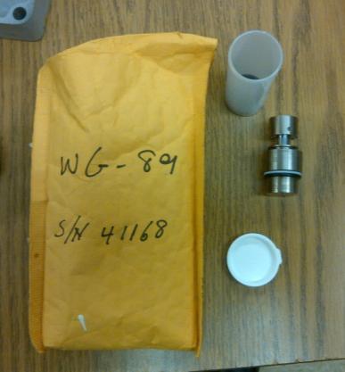
5 Piston/Cylinder Assembly Piston/Cylinder Assembly Inside the envelope Plastic vial Inside the vial Piston/Cylinder


6 Turn the pump on the pan Pump setup Section in manual Loosen (4) cap screws and remove Rotate pump 180 on same mount Reinstall (4) cap screws» Loosely keep from misplacing them» Allow for column alignment Not necessary for dual column units Cap screws


7 Column setup Remove fittings from manifold Section 3.2-2/3 in manual Remove plug from the front of the pump Remove fittings from one side of the manifold Install into the front of the pump Install plug onto manifold where fittings were removed» Customer may have additional fittings to use on manifold Fitting/Nut Plug Manifold As Shipped Manifold Fittings Removed Manifold Ready for Use


8 Column setup Connect and mount column Section to 6 in manual Install fitting from manifold into front of pump Set column onto pan Thread column fittings into nut on front of pump Tighten fittings» Use a backing wrench Install (3) cap screws to complete mounting of column Tighten (4) cap screws on pump to secure in place Fitting/Nut Column As Shipped Column and Pump Connected Column Mounted to Pan


9 Install manifold onto pump Mount Manifold Remove the plug from the top of the pump» This may be used on the manifold during the column fill process Place manifold on top of the pump in place of the plug Thread nut onto manifold and tighten» Use a backing wrench Install plug into open side of manifold and tighten Plug on Pump Tighten Manifold onto Pump Install Plug


10 Install Piston/Cylinder Assembly Prepare system for the installation of the piston/cylinder assembly Section 3.2-7/8 (partial) in manual Remove the (8) cap screws from the top of the carrier on the column Lift off the cylinder cap» Lift the pump handle and pull the displacement selector out This is the High Volume / Low Pressure position» Close the vent valve and pump until water is above the cylinder bevel in the column Cylinder Cap Displacement Selector Liquid in Column


11 Install cylinder Install Piston/Cylinder Assembly Section in manual Install cylinder into column Replace cylinder cap Tighten (4) cap screws» Use a cross pattern when tightening to prevent undue stress on parts This seats the cylinder Cylinder in Column Cylinder Seated
 cap screws and remove cylinder cap Pump until water is above the level of the cylinder Work piston into cylinder bore while using vent")
12 Install Piston Install Piston/Cylinder Assembly Section 3.2-8/10 in manual Remove (4) cap screws and remove cylinder cap Pump until water is above the level of the cylinder Work piston into cylinder bore while using vent valve to release water» Film of oil not necessary for water applications Water above Cylinder Piston Installed
 cap")
 cap screws» Tighten opposing screws in an")

13 Install Piston/Cylinder Assembly Replace cylinder cap Section /12 in manual Replace cylinder cap Tighten all (8) cap screws» Loosely install (4) cap screws and then the alternating (4) cap screws» Tighten opposing screws in an alternating pattern Rotate piston driver until it engages with drive pin on the piston Piston Driver Drive Pin Cap Screws Loose Tightening Screws

14 Ready for Testing Carrier Tube Pump Manifold Follow section 4.3 in the manual Weight #1 Conversion Weight
Type T Hydraulic Deadweight Tester
 pressure Specification Sheet SS-CP-2150-US Type T Hydraulic Deadweight Tester M&G Deadweight Testers Pressure ranges to 15,000 psi to 1,000 bar to 1,000 kg/cm 2 to 100,000 kpa Accuracies to 0.015% of reading.
Hawk Brake Pads ( Mustang GT/V6 Rear Pair)
") Hawk Brake Pads (1994-2004 Mustang GT/V6 Rear Pair) The below installation instructions work for the following products: Hawk HPS Brake Pads (1994-2004 Mustang GT/V6 Rear Pair) Hawk Performance Ceramic
Hawk Brake Pads (1994-2004 Mustang GT/V6 Rear Pair) The below installation instructions work for the following products: Hawk HPS Brake Pads (1994-2004 Mustang GT/V6 Rear Pair) Hawk Performance Ceramic
 Page 1 of 75 303-01D Engine - 5.2L 32V Ti-VCT 2016 Mustang Assembly Procedure revision date: 12/15/2016 Special Tool(s) / General Equipment Engine Base Part Number: 6L084 205-142 (T80T-4000-J) Installer,
Type T Pump. Operation Manual for T-1and T-1-CPF
 Type T Pump Operation Manual for T-1and T-1-CPF Contents Overview... 1 Introduction... 1 Features... 2 Setup... 3 Assembly... 3 Safety Instructions... 5 Warnings, Cautions, and Notes... 5 Operation and
WM Changing ATF
 Page 1 of 7 The present document was valid at the time of print. A later version may be available online WM 370255 Changing ATF Tools Designation Type Number Description Screw connection hose Special tool
Model Type T Hydraulic Deadweight Tester
 p r e s s u r e Model Type T Pressure Range 100 to 10,000 kpa (10 to 15,000 psi) Accuracy to ±0.015% of Indicated reading Accuracy ±0.025 and 0.100% is also available Repeatebility ±0.005% of Indicated
Model Type T Hydraulic Deadweight Tester
 Visit us at www.testequipmentdepot.com p r e s s u r e 99 Washington Street Melrose, MA 02176 Phone 781-665-1400 Toll Free 1-800-517-8431 Model Type T Pressure Range 100 to 10,000 kpa (10 to 15,000 psi)
ACHL Series Pump. Operation and Maintenance Manual Air Driven, Hand Operated High Pressure Liquid Pump
 ACHL Series Pump Operation and Maintenance Manual Air Driven, Hand Operated High Pressure Liquid Pump Catalog: 02-9245ME February 2013 Model # Serial # Drawing # Order # Mfg. Date Table of Contents page
TCI Trans-Scat
 Page 1 of 5 Return to Instruction Sheet index TCI 400000 Trans-Scat Turbo Hydramatic 400-1965-Up This kit will allow you to re-program your transmission valve body. This kit will give you firm positive
Common Rail Injector
 Common Rail Injector Installation Instructions & Information Common Rail Injector General Information WARNING WARNING CAUTION Fuel may be returned at highly elevated temperatures. Wear safety glasses and
TCI Turbo 400 Full Manual Valve Body. Shift Pattern: Park Reverse Neutral First Second Third. NOTE: You must reuse stock manual control valve.
 TCI 221100 Turbo 400 Full Manual Valve Body Shift Pattern: Park Reverse Neutral First Second Third This Kit Contains: (1) Turbo 400 Full Manual Valve Body (1) Separator Plate & Gaskets (1) Pressure Regulator
INSTALLATION INSTRUCTIONS
 INSTALLATION INSTRUCTIONS DUAL EXTERNAL PUMP FST Vertical & Horizontal Mount Customer Support: info@radiumauto.com Document: 19-0013 READ AND UNDERSTAND THESE INSTRUCTIONS COMPLETELY BEFORE BEGINNING INSTALLATION
INSTALLATION INSTRUCTIONS FOR THE TRUCK MOUNTED VIPER ADDITIVE INJECTION SYSTEM GTP-8776C
 INSTALLATION INSTRUCTIONS FOR THE TRUCK MOUNTED VIPER ADDITIVE INJECTION SYSTEM GTP-8776C This additive injection system was designed to be used with five gallon jug of additive. The system is supplied
Engine. Special Tool(s) Compressor, Piston Ring 303-D032 (D81L-6002-C) or equivalent. Compressor, Valve Spring (T93P-6565-AR)
 Compressor, Piston Ring 303-D032 (D81L-6002-C) or equivalent. Compressor, Valve Spring (T93P-6565-AR)") SECTION 303-01C: Engine 5.4L (4V) 2009 Mustang Workshop Manual ASSEMBLY Procedure revision date: 12/12/2008 Engine Special Tool(s) Compressor, Piston Ring 303-D032 (D81L-6002-C) or equivalent Compressor,
SECTION 303-01C: Engine 5.4L (4V) 2009 Mustang Workshop Manual ASSEMBLY Procedure revision date: 12/12/2008 Engine Special Tool(s) Compressor, Piston Ring 303-D032 (D81L-6002-C) or equivalent Compressor,
Installation, Operation, and Maintenance Manual
 Installation, Operation, and Maintenance Manual Welker Automatic Insertion Heated Regulator High Voltage Model IHRA-4SS-220/230 100 or more inch insertion length The information in this manual has been
IOM Manual. IOM Manual. Series 20/21.
 IOM Manual IOM Manual Series 20/21 www.flowlinevalves.com Flow Line Valve and Controls, L.L.C. 110 Main Project Road Schriever, LA 70395 P.O. Box 677 Schriever, LA 70395 Phone 985-414-6004 * Toll Free
Implement and Steering/Hydraulic System Testing and Adjusting
 Page 1 of 64 Testing And Adjusting Introduction Reference: This supplement contains the Specifications, Systems Operation, and Testing And Adjusting for the components and systems that are different than
ROOTS Meters Series B3 Meter Models 8C175-56M175
 ROOTS Meters Series B3 Meter Models 8C175-56M175 Refer to IOM-B3 for Complete Instructions IS:B3 3.03 RECEIVING, HANDLING AND STORAGE ROOTS rotary positive displacement gas meters are precision measurement
Release the electrical wire from the bracket -2- toward the left -A- and remove.
 Page 1 of 8 Front Brake Pads, FBC-60, Removing and Installing Always replace on both axles. Special tools and workshop equipment required t Torque Wrench 5 50 Nm -V.A.G 1331- t Reversible Ratchet -V.A.G.
Media Number -SENR Publication Date -01/10/1977 Date Updated -12/10/2001
 - - 55, 56, 57, 58 & 59 TOWING WINCHES Page 1 of 21 Testing and Adjusting 55, 56, 57, 58 & 59 TOWING WINCHES Media Number -SENR7217-01 Publication Date -01/10/1977 Date Updated -12/10/2001 Testing And
DP Series Diaphragm Valve Installation and Maintenance Instructions
 DP Series Diaphragm Valve Installation and Maintenance Instructions Contents Installation Actuation Actuator Orientation Welding Testing Maintenance Kit Contents Tool Requirements Exploded View Replacing
FORD RACING DIFFERENTIAL INSTALLATION (99-04 GT, Mach 1)
") FORD RACING DIFFERENTIAL INSTALLATION (99-04 GT, Mach 1) Time Necessary: Approximately 4 hours Tools Required: Wrenches: 8mm, 13mm, 15mm, 5.5 mm allen, 6mm allen Sockets: 5/8, 3/4 Ratchet Floor Jack Jack
FORD RACING DIFFERENTIAL INSTALLATION (99-04 GT, Mach 1) Time Necessary: Approximately 4 hours Tools Required: Wrenches: 8mm, 13mm, 15mm, 5.5 mm allen, 6mm allen Sockets: 5/8, 3/4 Ratchet Floor Jack Jack
The Driveshaft Shop One Piece Aluminum Driveshaft Install for GT/BOSS
 The Driveshaft Shop One Piece Aluminum Driveshaft Install for 2011-14 GT/BOSS Tools and Equipment needed: Install time: approximately 2-3 hours Ratcheting socket wrench socket extensions 1/2 drive breaker
Module. Section 9. NOTE: This section applies to applicators with CC200 modules B Issued 6/01. Manual 42-CF200-CM-01
 Section 9 NOTE: This section applies to applicators with CC200 modules. 9-0 Table of Contents i Table of Contents Section 9 1. Introduction............................................... 9-1 2. Specifications.............................................
Step 3: Remove the six 8mm retaining bolts for the pressure manifold switch assembly. The manifold switch will not be re-installed.
 1 INSTRUCTIONS TCI 274500/274501 4L80E Trans Brake Valve Body Thank you for choosing TCI products. We are proud to be your manufacturer of choice. Please read this instruction sheet carefully before beginning
Turbo 400 Trans Brake Valve Body Shift Pattern: Park Reverse Neutral 1st 2nd 3rd
 TCI 221500 Turbo 400 Trans Brake Valve Body Shift Pattern: Park Reverse Neutral 1st 2nd 3rd This Valve Body will neutralize at shut-down by putting shifter In 2nd gear position This Kit Contains: (1) Turbo
INSTALLATION INSTRUCTIONS MKIV Toyota Supra Manual Rack Conversion
 INSTALLATION INSTRUCTIONS MKIV Toyota Supra Manual Rack Conversion 1 Removal of Stock Rack 1.1 With your steering wheel centered, remove the pinch bolt from the factory intermediate shaft. This is located
Lifting height 5.5" - 72" with adapters " Height overall 165" Width between columns 122" Drive through 109" Width overall 151.
 Model Number TP12KC-D Capacity 12,000 lbs. Lifting height 5.5" - 72" with adapters 79.625" Height overall 165" Width between columns 122" Drive through 109" Width overall 151.125" Arm extension 37.5" -
Flow Line Controls. Installation & Operations Manual SERIES 20/21 Pneumatic Actuators
 Flow Line Controls Installation & Operations Manual SERIES 20/21 Pneumatic Actuators Flow Line Controls, Inc. P.O. Box 677 Schriever, LA 70395 Phone: 985-414-6003 Toll Free 1-800-815-9226 Fax 985-414-6072
Maintenance Supplies
 Maintenance Supplies 7. 8. 6. 15. 14. 13. 12. 10. 9. 2. 3. 5. 4. 11. 1. 1. TU-3 shown for demonstration purposes 2. Teflon tape 3. Center punch 4. 5/32 punch 5. 1/4 punch 6. 3/8 punch 7. Breaker bar with
GX-271 ASPEC Gilson, Inc. All Rights Reserved. LT
 GX-271 ASPEC GX-271 ASPEC World Headquarters Gilson, Inc. 3000 Parmenter Street P.O. Box 620027 Middleton, WI 53562-0027 USA Telephone: 608-836-1551 Fax: 608-831-4451 Gilson S.A.S. 19, avenue des Entrepreneurs
Disassembly and Assembly
 K EN R 623 2-00 August 2006 Disassembly and Assembly 2506-15 Industrial Engine M G A (Engine) MGB (Engine) M G D (Engine) Important Safety Information Most accidents that involve product operation, maintenance
User Manual for the ProFlow 1K Release: User Manual for the ProFlow 1K_Rev_A PVA Support Hub. User Manual for the ProFlow 1K
 PVA Support Hub User Manual for the ProFlow 1K Collection of guides and pages for the operation and maintenance of the ProFlow 1K. Written By: Technical Writing 2017 support.pva.net Page 1 of 18 INTRODUCTION
Filter. Table of Contents. Section 10. Filter NOTE: This section applies to applicators with a threaded filter.
 Filter 10-1 Section 10 Filter NOTE: This section applies to applicators with a threaded filter. Table of Contents Filter... 10-1 Introduction... 10-3 Filter Overview... 10-3 Filter Service... 10-4 Relieving
Cylinder Head. Special Tool(s) Compressor, Valve Spring (T93P-6565-AR) Heavy Duty Floor Crane or equivalent
 Compressor, Valve Spring (T93P-6565-AR) Heavy Duty Floor Crane or equivalent") SECTION 303-01C: Engine 5.4L (4V) 2009 Mustang Workshop Manual INSTALLATION Procedure revision date: 04/03/2009 Cylinder Head Special Tool(s) Compressor, Valve Spring 303-452 (T93P-6565-AR) Heavy Duty
SECTION 303-01C: Engine 5.4L (4V) 2009 Mustang Workshop Manual INSTALLATION Procedure revision date: 04/03/2009 Cylinder Head Special Tool(s) Compressor, Valve Spring 303-452 (T93P-6565-AR) Heavy Duty
CHANGING AUTOMATIC TRANSMISSION FLUID
 CHANGING AUTOMATIC TRANSMISSION FLUID Changing your automatic transmission fluid yourself is a quick and simple process when you know how! To help you out, we ve put together a quick step-by-step guide
1997 Volkswagen Jetta GT AUTOMATIC TRANSMISSIONS' 'Servicing - Volkswagen AUTOMATIC TRANSMISSIONS. Servicing - Volkswagen
 1997-98 AUTOMATIC TRANSMISSIONS Servicing - Volkswagen APPLICATION TRANSAXLE APPLICATION Application Transaxle Model 1997 Golf, GTI, Jetta & Passat 01M 1998 Jetta, Golf, GTI 01M LUBRICATION CHECKING FLUID
Cable Shift Linkage Kit
 Cable Shift Linkage Kit INSTALLATION INSTRUCTIONS ididit column to GM Trans FOR PART NUMBER S: 2801000010, 2802000010 ididit Column to 350 Trans...Pg 1-4 ididit Column to 400 Trans...Pg 5-8 ididit Column
Filter. Table of Contents. Section 10. Filter NOTE: This section applies to applicators with a Universal in-out filter.
 Filter 10-1 Section 10 Filter NOTE: This section applies to applicators with a Universal in-out filter. Table of Contents Filter...................................................... 10-1 Introduction................................................
Disassembly and Assembly
 SENR9973-01 September 2007 Disassembly and Assembly 400C Industrial Engine HB (Engine) HD (Engine) HH (Engine) HL (Engine) HM (Engine) HN (Engine) HP (Engine) HR (Engine) Important Safety Information Most
8000 Pump Maintenance
 8000 Pump Maintenance Perform Forward System Purge Before Performing Pump Maintenance Pump Must Be Removed From Enclosure To Service. Use Repair Kit P/N D3-0102 8000 Pump Removed From Enclosure Special
ENG-16, Turbocharger Replacement (Including Tips on K27 Turbocharger Installation)
") ENG-16, Turbocharger Replacement (Including Tips on K27 Turbocharger Installation) Introduction Replacing the turbocharger on a 951 is not extremely difficult. However, it is very tedious because there
ENG-16, Turbocharger Replacement (Including Tips on K27 Turbocharger Installation) Introduction Replacing the turbocharger on a 951 is not extremely difficult. However, it is very tedious because there
Propeller Assembly. 1. General
 Propeller Assembly GENERAL 61-10: PROPELLER ASSEMBLY 1. General The propeller assembly consists of a hollow aluminum hub which supports the propeller blades and also houses the pitch changing mechanism.
FRP SystemOne GELCOATER OPERATION MANUAL. MAGNUM VENUS PRODUCTS Operation Manual. Part No. M Revision
 1300-1-1 GELCOATER OPERATION MANUAL MAGNUM VENUS PRODUCTS Operation Manual Part No. M1300-1-1 Revision 04.26.01 Operation Manual Unit Information Unit # Type Of: Power Cylinder Metering Pump Gun Fluid
Module. Table of Contents. Section 9. Module NOTE: This section applies to applicators with bead or slot modules.
 9-1 Section 9 NOTE: This section applies to applicators with bead or slot modules. Table of Contents... 9-1 Introduction... 9-3 Overview... 9-7 Service... 9-9 Adjusting a ClassicBlue Zero-Cavity... 9-9
Oregon Fuel Injection
 Cummins PT Fuel Pump Diagnostic No Start, with no smoke 1. This could be caused by the fuel pump not turning or a seized gear pump. Remove the fuel supply hose and the fuel inlet fitting from the gear
Replacing a Gun RTD. Instruction Sheet P/N B. 1. Introduction. Using this Instruction Sheet
 Instruction Sheet Replacing a Gun RTD WARNING: Allow only qualified personnel to perform the following tasks. Observe and follow the safety instructions in this document and all other related documentation.
Thanks for Ordering The Vulcan 800A Front Wheel Adapter from READ THIS BEFORE UNPACKING YOUR KIT!
 Thanks for Ordering The Vulcan 800A Front Wheel Adapter from READ THIS BEFORE UNPACKING YOUR KIT! This instruction booklet contains detailed steps for installation of your Vulcan 800A Front Wheel Adapter
6. CYLINDER HEAD/CYLINDER/PISTON
 6 6 CYLINDER HEAD/CYLINDER/PISTON SERVICE INFORMATION... 6-2 TROUBLESHOOTING... 6-2 CYLINDER HEAD... 6-3 CYLINDER/PISTON... 6-6 6-0 Torque: 1.1~1.7kg-m (cold) Torque: 1.5~1.7kg-m 6-1 SERVICE INFORMATION
Pull out clutch E snap ring and withdraw complete clutch pack of clutch E. 6 HP 26 ZF Getriebe GmbH Saarbrücken CD
 Press down cup spring in the mandrel press with assembly bracket 5x46 002 566 and remove snap ring with suitable pliers. Take out planet carrier and cup spring. Take the O-ring seal off the planet carrier.
EP-2 Si Three-Piston Pump
 EP- Si Three-Piston Pump Customer Product Manual Issued 0/ For parts and technical support, call the Industrial Coating Systems Customer Support Center at (800) -99 or contact your local Nordson representative.
MERCEDES AMG45 HPFP UPGRADE
 MERCEDES AMG45 HPFP UPGRADE WARNING/DANGER: SERIOUS RISK OF FIRE, EXPLOSION, BODILY INJURY INCLUDING RESULTING DEATH, AND ENGINE, VEHICLE, AND OTHER PROPERTY DAMAGE. THIS FUEL PUMP MUST BE INSTALLED AND
TCI TRANS-SCAT
 Page 1 of 9 Return to Instruction Sheet index TCI 360000 TRANS-SCAT Installation Instructions for FORD C-6 Transmissions TCI s TRANS-SCAT kit will allow you to calibrate the performance of your transmission.
TH400 STREETFIGHTER SERIES VALVE BODY MANUAL/AUTO VALVE BODY INSTALLATION INSTRUCTIONS
 1 INSTRUCTIONS TH400 STREETFIGHTER SERIES VALVE BODY 1965-87 MANUAL/AUTO VALVE BODY INSTALLATION INSTRUCTIONS TCI 222400 TCI 222400 ALLOWS AUTOMATIC SHIFT FEATURES IN THE DRIVE POSITION Thank you for choosing
Installation Instructions and Warranty Information
 Corporate Office: PerTronix Inc. 440 E. Arrow Highway, San Dimas, California 91773 * Phone 909.599.5955 FAX 909.599.6424 Installation Instructions and Warranty Information Part # 1400S 2004-16 Nissan Armada
Agilent 210/218 - Isocratic Pump
 Agilent 210/218 - Isocratic Pump Installation of the Stainless Steel Tubing Kit Introduction This technical note shows you how to install the Stainless Steel Tubing Kit for the isocratic pump of the Agilent
KEITH WALKING FLOOR RUNNING FLOOR II Drive Repair Instructions
 Load-Unload Control Valve Handle Assembly Handle Assembly Switching Valve LOAD END DISCHARGE END Adapter Block Ball Valve Cylinder #1 Cylinder #2 Check Valve #1 Check Valve #2 Adapter Block Cylinder #3
Agilent 210/218 - Binary Pump
 Agilent 210/218 - Binary Pump Installation of the Stainless Steel Tubing Kit Introduction This technical note shows you how to install the Stainless Steel Tubing Kit for the binary pump of the Agilent
PINPOINT TEST B: TRANSMISSION FLUID TEMPERATURE (TFT) SENSOR
 SENSOR") PINPOINT TEST B: TRANSMISSION FLUID TEMPERATURE (TFT) SENSOR NOTE: Refer to the Transmission Vehicle Harness Connector illustration preceding these pinpoint tests. NOTE: This vehicle is equipped with a
PINPOINT TEST B: TRANSMISSION FLUID TEMPERATURE (TFT) SENSOR NOTE: Refer to the Transmission Vehicle Harness Connector illustration preceding these pinpoint tests. NOTE: This vehicle is equipped with a
Diesel Technology: Engines
 Diesel Technology: Engines NATEF Crosswalk The following NATEF Diesel Engines tasks (rev. 2004) are covered in this publication. The chart shows where each task is located within the publication. The first
INSTALLATION INSTRUCTIONS LOKAR COLUMN SHIFT LINKAGE
 INSTALLATION INSTRUCTIONS LOKAR COLUMN SHIFT LINKAGE Part No. ACA-1807 (Ford AOD) STOP! PLEASE READ ALL INSTALLATION INSTRUCTIONS BEFORE BEGINNING INSTALLATION. CALL LOKAR FOR ANY QUESTIONS OR UNCERTAINTIES
HEAVY DUTY PNEUMATIC TORQUE WRENCH (C-RAD) USER GUIDE
 USER GUIDE") HEAVY DUTY PNEUMATIC TORQUE WRENCH (C-RAD) USER GUIDE Ref: WCOI.041 Date: June 2015 Issue: 4 Page Description CONTENTS 1 Introduction Training Requirements 2 General Safety 3 C-RAD Wrench Models Covered
HEAVY DUTY PNEUMATIC TORQUE WRENCH (C-RAD) USER GUIDE Ref: WCOI.041 Date: June 2015 Issue: 4 Page Description CONTENTS 1 Introduction Training Requirements 2 General Safety 3 C-RAD Wrench Models Covered
1983 BMW 320i. 1.8L 4-CYL 1983 Engines - 1.8L 4-Cylinder Engines - 1.8L 4-Cylinder
 ENGINE IDENTIFICATION 1.8L 4-CYL 1983 Engines - 1.8L 4-Cylinder For engine repair procedures not covered in this article, see ENGINE OVERHAUL PROCEDURES - GENERAL INFORMATION article in the GENERAL INFORMATION
INSTALLATION INSTRUCTIONS COMMERCIAL ROOM VENTILATORS WITH EXHAUST
 INSTALLATION INSTRUCTIONS COMMERCIAL ROOM VENTILATORS WITH EXHAUST MODEL CRVMP-5 For Use with Bard 3 through 5 Ton Wall Mount Air Conditioners and Heat Pumps Bard Manufacturing Company Bryan, Ohio 43506
Filter. Table of Contents. Section 10. Filter NOTE: This section applies to applicators with an in-out filter.
 Filter 10-1 Section 10 Filter NOTE: This section applies to applicators with an in-out filter. Table of Contents Filter...................................................... 10-1 Introduction................................................
EP-2 Three-Piston Pump
 EP- Three-Piston Pump Customer Product Manual Issued 0/ For parts and technical support, call the Industrial Coating Systems Customer Support Center at (800) -99 or contact your local Nordson representative.
Effective June 2016 New Issue
 Voltage Regulators MN225035EN Effective June 2016 New Issue COOPER POWER SERIES QD8 Quik-Drive Tap-Changer Switch Assembly Kit 5740785B13 and Switch Neutral Stationary Assembly Kit 5791646A48 Installation
 Page 1 of 7 Section 07-01A: Transmission, Automatic, E4OD IN-VEHICLE SERVICE 1993 Bronco/Econoline/F-Series Workshop Manual Valve Bodies and Intermediate Band Servo NOTE: If a transmission has been disassembled
Attention! The following must be done to maintain consistent staging with all Tranz Brake Valve Bodies for Three (3) Speed Automatics: Before
 Speed Automatics: Before") Attention! The following must be done to maintain consistent staging with all Tranz Brake Valve Bodies for Three (3) Speed Automatics: Before turning bottom final stage yellow light on, you should be at
Attention! The following must be done to maintain consistent staging with all Tranz Brake Valve Bodies for Three (3) Speed Automatics: Before turning bottom final stage yellow light on, you should be at
M-6007-B50/B51/XE3/XB3 Engine INSTALLATION INSTRUCTIONS
 Please visit www.fordracingparts.com for the most current instruction information!!! PLEASE READ ALL OF THE FOLLOWING INSTRUCTIONS CAREFULLY PRIOR TO INSTALLATION. AT ANY TIME YOU DO NOT UNDERSTAND THE
Information and Instructions
 Information and Instructions This individual shop manual is one unit of a series on wheel type tractors. Contained in it are the necessary specifications and the brief but terse procedural data needed
INSTALLATION STEPS PLEASE READ THESE INSTRUCTIONS COMPLETELY BEFORE BEGINNING INSTALLATION TOOLS REQUIRED
 INSTALLATION STEPS PLEASE READ THESE INSTRUCTIONS COMPLETELY BEFORE BEGINNING INSTALLATION TOOLS REQUIRED TAPE MEASURE PERMANENT MARKER PHILLIPS HEAD SCREWDRIVER ADJUSTABLE WRENCH 3/16 ALLEN WRENCH 9/16
OPERATOR'S MANUAL AND MAINTENANCE INFORMATION MODEL T-2000 TEXTURE TEST SYSTEM
 OPERATOR'S MANUAL AND MAINTENANCE INFORMATION MODEL T-2000 TEXTURE TEST SYSTEM This Publication contains information proprietary To Food Technology Corporation The contents of this publication may not
Smittybilt XRC Rear Bumper Installation Guide Part # 76856
 Installation Difficulty: Easy Installation Duration: 2 Hours Tools Needed: Smittybilt XRC Rear Bumper Installation Guide Part # 76856-13, 16, 17, 18, 19mm wrenches and/or sockets - Socket extension - Torque
Cable Shift Linkage Kit
 Cable Shift Linkage Kit INSTALLATION INSTRUCTIONS ididit column to Ford 4R70W/AODE Trans FOR PART NUMBER S: 2801600010, 2802600010 S INCE 1986 www.ididitinc.com 610 S. Maumee St., Tecumseh, MI 49286 PH:
Welker Jet Insert Model Control Valve
 Welker Jet Insert Model Control Valve Model WJ-1N, WJ-2N, WJ-4N, WJ-6N, & WJ-8N The information in this manual has been carefully checked for accuracy and is intended to be used as a guide for the installation,
IBM UPS Extend Run Battery Pack Operation and Setup Guide
 IBM UPS Extend Run Battery Pack Operation and Setup Guide 02R2717 1: INSTALLATION Introduction The IBM Uninterruptible Power Supply (UPS) Extend Run Battery Pack provides extended load protection and
INSTALLATION, OPERATION AND MAINTENANCE MANUAL FOR INSTRUMENT ISOLATION VALVE
 PAGE : 01 OF 07 INSTALLATION, OPERATION AND MAINTENANCE MANUAL FOR INSTRUMENT ISOLATION VALVE PREPARED BY CHECKED BY APPROVED BY NAME M.Bhuvaneswari Y.Nesabalan M.Selvam DATE 22-Mar-201 19-Nov-2013 22-Nov-2013
Chang Jiang 750 OHV engine repair
 Chang Jiang 750 OHV engine repair This applies specifically to the CJ750F1 and CJ750F1a OHV engines, the latter having different oil pump gearing, a take-off point for a tachometer, and an output for an
D6 Crawler S/n 37A1 & 44A1 & up
 Caterpillar Service Manual D6 Crawler S/n 37A1 & 44A1 & up Service Manual THIS IS A MANUAL PRODUCED BY JENSALES INC. WITHOUT THE AUTHORIZATION OF CATERPILLAR OR IT S SUCCESSORS. CATERPILLAR AND IT S SUCCESSORS
IMPORTANT!!!! Read this manual before attempting any installation, wiring or operation.
 Industrial Turbo Meters Sizes 2" through 6" Installation & Operation Manual IMPORTANT!!!! Read this manual before attempting any installation, wiring or operation. BadgerMeter,Inc. IOM-003-15 Part No.
P5510. Users Manual. Pneumatic Comparison Test Pump. Test Equipment Depot Washington Street Melrose, MA TestEquipmentDepot.
 Test Equipment Depot - 800.517.8431-99 Washington Street Melrose, MA 02176 TestEquipmentDepot.com P5510 Pneumatic Comparison Test Pump Users Manual PN 3952297 November 2010 2010 Fluke Corporation. All
Welker Heated Instrument Regulator
 Installation, Operation, and Maintenance Manual Welker Heated Instrument Regulator Model The information in this manual has been carefully checked for accuracy and is intended to be used as a guide for
What s Included. All items included. Please be familiar with the names of all the accessories listed here. NOTES:
 JWX-30 Setup What s Included All items included Please be familiar with the names of all the accessories listed here. What s Included Cont. All items included Please be familiar with the names of all the
P3000 Series. Users Manual. Pneumatic Deadweight Tester
 P3000 Series Pneumatic Deadweight Tester Users Manual PN 3952260 November 2010 2010 Fluke Corporation. All rights reserved. Printed in USA. Specifications are subject to change without notice. All product
Ampco ZP3 Series (Addendum) Positive Displacement Pumps Installation and Maintenance Manual
 Positive Displacement Pumps Installation and Maintenance Manual") Ampco ZP3 Series (Addendum) Positive Displacement Pumps Installation and Maintenance Manual Pump Disassembly 1) Start by removing the cover nuts with an appropriate wrench (Figure 1). During disassembly
Ampco ZP3 Series (Addendum) Positive Displacement Pumps Installation and Maintenance Manual Pump Disassembly 1) Start by removing the cover nuts with an appropriate wrench (Figure 1). During disassembly
OPERATION MANUAL FOR SQUARE DRIVE & LOW PROFILE HYDRAULIC TORQUE WRENCHES NOTICE WARNING
 OPERATION MANUAL FOR SQUARE DRIVE & LOW PROFILE HYDRAULIC TORQUE WRENCHES NOTICE Hydraulic Torque Wrenches are designed for installing and removing large bolts having minimal wrench clearance at offshore
AJV8 Engine Assembly. AJV8 Engine Assembly
 AJV8 Engine Assembly Contents Cylinder Block Dowels, Plugs and Pipes 2 4 Crankshaft Bearing and Cylinder Bore Dimensions 5 9 Bearing Measuring 6 Engine Dimensions and Codes 6 7 Main Bearing Selection Chart
3208 Diesel Truck Engine Serial Number 40S1 & Up
 Caterpillar Service Manual 3208 Diesel Truck Engine Serial Number 40S1 & Up Service Manual THIS IS A MANUAL PRODUCED BY JENSALES INC. WITHOUT THE AUTHORIZATION OF CATERPILLAR OR IT S SUCCESSORS. CATERPILLAR
INSTALLATION INSTRUCTIONS CATCH CAN KIT
 INSTALLATION INSTRUCTIONS CATCH CAN KIT FORD FOCUS Document: 19-0150 Support: info@radiumauto.com STEPS 1 TO 19 COVER THE PCV CATCH CAN KIT (P/N: 20-0315) STEPS 20-32 COVER THE CRANKCASE CATCH CAN KIT
CYLINDER HEAD/CYLINDER/PISTON
 6 CYLINDER HEAD/CYLINDER/PISTON 6 SERVICE INFORMATION... 6-3 TROUBLESHOOTING... 6-3 CYLINDER HEAD... 6-4 CYLINDER/PISTON... 6-8 6-0 SH10AA Torque: 1.1 1.7kg-m (cold) Torque: 1.5 1.7kg-m 6-1 SH10BA Torque:
Adjusting the PRS Z-Axis Bearings
 888-680-4466 ShopBotTools.com Adjusting the PRS Z-Axis Bearings Copyright 2016 ShopBot Tools, Inc. page 1 Copyright 2016 ShopBot Tools, Inc. page 2 Introduction This document describes how to adjust the
PRELIMINARY. Engine Speed Standby Power Prime Power Continuous Power. RPM kwm BHP kwm BHP kwm BHP. Litre / hour
 Cummins Inc. Columbus, Indiana 47201 Engine Data Sheet Basic Engine Model: 1-G8 Engine Critical Parts List: CPL: 2816 Curve Number: FR-10302 Date: 3Oct01 1 Displacement : 1 liter (912 in 3 ) Bore : 137
MICHIGAN FLUID POWER
 MICHIGAN FLUID POWER Air Driven Hydraulic Pumps, Power Units and Intensifiers P901 Installation, Use and Maintenance Manual Contents Introduction, Guarantee and Identification Plate Description, Start
Torqueflite Trans-Scat Kit
 TCI 220000 Torqueflite Trans-Scat Kit This kit can be installed in a few hours by carefully following directions. Read all instructions first to familiarize yourself with the parts and procedures. Work
IN-VEHICLE REPAIR Procedure revision date: 12/15/ Position the vehicle on a hoist. For additional information, refer to Section
 2002 F-150 Applies to: 4R100 Report a problem with this article SECTION 307-01A: Automatic Transmission 4R100 2002 F-150 Workshop Manual IN-VEHICLE REPAIR Procedure revision date: 12/15/2003 Main Control
Exhaust Heat Shield Instructions ND
 Exhaust Heat Shield Instructions ND 2016 + Thank you for purchasing the Track Dog Racing Exhaust Heat Shield for the 2016 to Present Mazda MX-5. Our TDR Heat Shield is designed to help maintain lower temperatures
75L & 100L JACKETED ASSEMBLY INSTRUCTIONS FOR PROCESS REACTOR SYSTEMS N. Mill Road Vineland, NJ Phone: Fax:
 3800 N. Mill Road Vineland, NJ 08360 Phone: 800.843.1794 Fax: 800.922.4361 ASSEMBLY INSTRUCTIONS FOR 75L & 100L JACKETED PROCESS REACTOR SYSTEMS 1/4 HP Electric Stirrer Motor High Efficiency Condenser
Engine, removing and installing
 Стр 1 из 16 10-1 Engine, removing and installing Special tools, testers and auxiliary items required Torque wrench VAG 1331 Torque wrench VAG 1332 Engine/transmission jack VAG 1383 A Spring type clip pliers
Installation Guide. Flame Ionization Detector on a 6850 GC Accessory G2621
 Installation Guide Flame Ionization Detector on a 6850 GC Accessory G2621 2 Agilent Technologies 2007 All Rights Reserved. Reproduction, adaptation, or translation without permission is prohibited, except