Maintenance Supplies
|
|
|
- Arleen Lane
- 5 years ago
- Views:
Transcription
1
 14. Ratchet 15.")
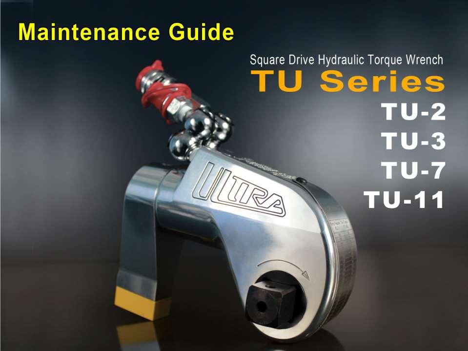
2 Maintenance Supplies TU-3 shown for demonstration purposes 2. Teflon tape 3. Center punch 4. 5/32 punch 5. 1/4 punch 6. 3/8 punch 7. Breaker bar with 7/8 socket 8. TU-3 gland wrench 9. 1/8 allen wrench 10. Brass drift 11. 1/4 allen wrench 12. Marine moly 13. Hammer (18 oz.) 14. Ratchet 15. Light grease

3 Remove factory installed reaction arm

4 With 1/8 allen wrench gently remove top shroud screw

5 Remove top shroud Note tension on shroud. The shroud will spring open, once screw is removed

6 Remove bottom shroud screw with 1/8 allen wrench

7 Remove torque chart engraved shroud and set aside

8 Remove run down spring for slotted drive plate

9 Displaying run down spring

10 Remove square drive retaining pin with 1/8 allen wrench

11 Remove square drive

12 Remove roll pin using 5/32 punch and (18 oz.) hammer

13 Roll pin removed

14 Remove drive plate

15 Remove sleeves and on older tools, the sleeve o-rings

16 Remove segment and ratchet from drive plate

17 Segment spring Be aware of tension on segment spring to prohibit spring ejection

18 Use a vise to place tool in

19 Remove both swivels from tool with ¼ allen wrench and place aside

20 Turn tool around in vice and insert gland wrench into gland

21 Gland wrench installed

22 Use breaker bar with 7/8 socket on top of gland wrench and loosen
 and put")
23 Remove gland (showing threads) and put aside

24 Brass gland with rod seal

25 Housing showing gland removed

26 Place rag in vice and under tool to catch parts

27 Use hammer and 3/8 punch placed in end plug
 hit down on 3/8")
28 With hammer(18oz.) hit down on 3/8 punch

29 Showing piston rod assembly and end plug resting on rag

30 Clean and inspect parts

31 Reassemble tool by first putting housing into vise

32 Light grease used to reassemble tool

33 Apply grease to end plug and end plug seal

34 Place end plug into housing

35 Press down until end plug seats itself
 hammer until end plug is ¼ below original seated")
36 Hit down on end plug with brass drift and (18oz.) hammer until end plug is ¼ below original seated position

37 Grease piston rod and piston rod seal and place into housing
38 Piston rod assembly positioned in housing

39 Hit down on piston rod assembly with brass drift and hammer, driving both the piston rod assembly and end plug to the bottom of the housing bore
40 Piston rod assembly shown in position

41 Place gland with rod seal into position

42 Place gland wrench into gland

43 Tighten gland into position using a 7/8 socket
44 Gland fully tightened should be flush with housing

45 Using center punch, positioned on the line separating the brass and aluminum, put a stay so the gland will not loosen during operation of the tool

46 Grease inside of the drive plate

47 Grease piston area of the drive plate

48 Wrong Direction Correct Direction

49 Install ratchet and segment in drive plate. Install segment spring Be aware of tension on segment spring to prohibit spring ejection

50 Install second segment spring and you have completed drive plate assembly

51 Remove old teflon tape and wrap 1 st and 2 nd swivels with new tape

52 Place tool in vise and reinstall both swivels with 1/4 allen wrench and tighten into advance port and retract port

53 Reinstall sleeves and sleeve O rings

54 Reinstall opposite side sleeves and O rings

55 Line up piston with 1/8 allen wrench

56 Install drive plate assembly

57 Drive plate assembly positioned in housing

58 Line up piston rod and drive plate with 5/32 punch

59 View showing 5/32 punch passing through housing, drive plate and piston rod

60 Remove 5/32 punch
61 View showing roll pin being inserted into tool

62 View showing roll pin partially inserted into drive plate

63 Drive roll pin into position using a ¼ punch and (18oz.) hammer

64 Picture shows roll pin is NOT engaged

65 Picture shows roll pin IS engaged

66 Insert square drive

67 Tighten square drive screw with 1/8 allen wrench

68 Reinstall run down spring

69 Run down spring installed

70 Reinstall bottom shroud screw 1/8 allen wrench

71 Reinstall top shroud screw with 1/8 allen wrench

72 Assembly completed
73
74

75

76 You have just completed the Maintenance Guide. For additional questions please contact: TorcUP Inc Conroy Place Easton, PA TorcUP Inc. is not responsible for customer modification of tools for applications on which TorcUP Inc was not consulted. Refer to the tool manual for safety and regulations.
MANUAL. TU Series. TU Series. Square Drive Hydraulic Torque Wrenches MODELS TU-2, TU-3, TU-5, TU-7, TU-11, TU-20, TU-27 & TU-60
 TU Series OPERATION AND MAINTENANCE MANUAL TU Series Square Drive Hydraulic Torque Wrenches MODELS TU-2, TU-3, TU-5, TU-7, TU-11, TU-20, TU-27 & TU-60 1025 Conroy Place, Easton, PA. 18040 U.S.A. Phone:
MANUAL. TU Series. TU Series Hydraulic Torque Wrenches MODELS TU-2, TU-3, TU-7, TU-11, TU-20, TU-27 & TU-60 OPERATION AND MAINTENANCE
 TU Series OPERATION AND MAINTENANCE MANUAL TU Series Hydraulic Torque Wrenches MODELS TU-2, TU-3, TU-7, TU-11, TU-20, TU-27 & TU-60 1025 Conroy Place, Easton, PA. 18040 * U.S.A. Phone: +1 610-250-5800
T O R Q U E C A T A L O G
 TORQUE CATALOG Never a ME-Too Company At TorcUP, our constant pursuit of Being Different maintains the strong link between the company of today and our founding year of 1996. With a steely determination
Installation Instructions COMPETITION/PLUS SHIFTER Ford Mustang MT82 6-Speed Manual Transmission Catalog#
 Installation Instructions COMPETITION/PLUS SHIFTER 2015-2017 Ford Mustang MT82 6-Speed Manual Transmission Catalog# 3916037 Rev. 00 WORK SAFELY! For maximum safety, perform this installation on a clean,
Installation Instructions INDY SHIFTER Fits: Mustang Fastback & Convertible with MT-82 Transmission Catalog #
 Installation Instructions INDY SHIFTER Fits: 2015-2018 Mustang Fastback & Convertible with MT-82 Transmission Catalog # 3916036 Watch our installation video on YouTube WORK SAFELY! For maximum safety,
SERVICE INSTRUCTIONS FOR SEAL REPLACEMENT OF POWER GEAR HYDRAULIC LEVELING LEGS
 SERVICE INSTRUCTIONS FOR SEAL REPLACEMENT OF POWER GEAR HYDRAULIC LEVELING LEGS 82-L0352 REV 8 4-27-2011 WARNING! HYDRAULIC COMPONENTS CAN CAUSE SERIOUS INJURY OR DEATH IF PROPER SAFETY PRECAUTIONS ARE
MP and MP Diaphragm and Seal Kits for MP8000 Series Actuators
 MP8000-6325 and MP8000-6350 Diaphragm and Seal Kits for MP8000 Series Actuators Contents of the MP8000-6325 Diaphragm and Seal Kit for MP82 and MP83 Actuators One seal, 5/8 in. Internal Diameter (I.D.)
Service Handbook High-Pressure Washer Pump
 Service Handbook High-Pressure Washer Pump 9.120-014.0 2 A. Water Inlet Filter C. Nozzle Insert 1. Remove filter with a screwdriver. 2. Clean filter with warm water and mild soap. 3. Reinstall filter.
HURST COMP/PLUS SHIFTER 2015 Ford Mustang (Getrag MT82 six-speed manual transmission) Catalog # by Hurst Performance
 Catalog # by Hurst Performance") FORM 159 0205 07/15 HURST COMP/PLUS SHIFTER 2015 Ford Mustang (Getrag MT82 six-speed manual transmission) Catalog #391 0205 2015 by Hurst Performance Thank you for purchasing the Hurst Comp/Plus Shifter.
FORM 159 0205 07/15 HURST COMP/PLUS SHIFTER 2015 Ford Mustang (Getrag MT82 six-speed manual transmission) Catalog #391 0205 2015 by Hurst Performance Thank you for purchasing the Hurst Comp/Plus Shifter.
TCI Trans-Scat
 Page 1 of 5 Return to Instruction Sheet index TCI 400000 Trans-Scat Turbo Hydramatic 400-1965-Up This kit will allow you to re-program your transmission valve body. This kit will give you firm positive
ALLOY USA AXLE INSTALLATION (99-04 GT, Mach 1)
") ALLOY USA AXLE INSTALLATION (99-04 GT, Mach 1) Time Necessary: Approximately 4 hours Tools Required: Wrenches: 8mm, 13mm, 15mm, 5.5 mm allen, 6mm allen Sockets: 5/8, 3/4 Ratchet Floor Jack Jack Stands
ALLOY USA AXLE INSTALLATION (99-04 GT, Mach 1) Time Necessary: Approximately 4 hours Tools Required: Wrenches: 8mm, 13mm, 15mm, 5.5 mm allen, 6mm allen Sockets: 5/8, 3/4 Ratchet Floor Jack Jack Stands
Service Bulletin. HIITMill (X) Brake Lever Drift
 Brake Lever Drift") HIITMill (X) Brake Lever Drift Applies to: HIITMill (9-4590) + HIITMIll X (9-4640) On some HIITMill and HIITMill X units, the brake lever can drift when the user is Rev. A applying load to the belt. This
HIITMill (X) Brake Lever Drift Applies to: HIITMill (9-4590) + HIITMIll X (9-4640) On some HIITMill and HIITMill X units, the brake lever can drift when the user is Rev. A applying load to the belt. This
rings used in the TuckAway Electric Monitor (#3352)
") STYLE 3352 O-Ring Ring Replacement Guide The following tools & materials are required for disassembly & servicing of the O-rings rings used in the (#3352) 5/64 Allen wrench 7/64 Allen wrench* 3/16 Allen
STYLE 3352 O-Ring Ring Replacement Guide The following tools & materials are required for disassembly & servicing of the O-rings rings used in the (#3352) 5/64 Allen wrench 7/64 Allen wrench* 3/16 Allen
Installation Manual TWM Performance Short Shifter Subaru STi 2008+
 - 1 - Installation Manual TWM Performance Short Shifter Subaru STi 2008+ Please Note: It is preferable to park on a flat surface, as you will have to engage and disengage the hand brake and shift from
Wiper Transmission Repair Charles Bernhardt
 Wiper Transmission Repair Charles Bernhardt When I purchased this '59 Corvette most of the parts were in boxes. The wiper transmissions were one of the first parts that I decided to look at to see if they
SERIES OPERATION AND MAINTENANCE MANUAL
 SERIES OPERATION AND MAINTENANCE MANUAL This manual CONTAINS IMPORTANT WARNINGS, S and OTHER INSTRUCTIONS. Read and understand the instruction manual Carefully, before use and retain it for reference.
Bolt Tensioning Technology for Wind Turbines
 Bolt Tensioning Technology for Wind Turbines www.torcup.com WTB Series Fully aware of the difficulties associated with wind turbine blade tensioning, the new TorcUP WTB Series is a purpose designed range
Operation and Maintenance Manual for BS and BH Hydraulic Torque Wrenches
 BOLTORQ Operation and Maintenance Manual for BS and BH Hydraulic Torque Wrenches It is operating manual of BS series and BH series wrenches, please read carefully and follow the instructions. Warning and
MODEL PRECISION MADE IN SWITZERLAND AND DISTRIBUTED EXCLUSIVELY BY M-B COMPANIES, INC. IN NORTH AMERICA
 kamber PAINT GUN MODEL 38-20 PRECISION MADE IN SWITZERLAND AND DISTRIBUTED EXCLUSIVELY BY M-B COMPANIES, INC. IN NORTH AMERICA Pavement Marking Equipment Divisions Eastern Region 79 Montgomery Street Montgomery,
Sachs shock manual. ( ) 2 & 4 Stroke RR Enduro. ( ) RS Dual Sport
 2 & 4 Stroke RR Enduro. ( ) RS Dual Sport") Sachs shock manual (2013 2015) 2 & 4 Stroke RR Enduro (2014-2015) RS Dual Sport 1 Introduction The procedures in this manual must take place in a clean environment using professional tools and some specific,
Sachs shock manual (2013 2015) 2 & 4 Stroke RR Enduro (2014-2015) RS Dual Sport 1 Introduction The procedures in this manual must take place in a clean environment using professional tools and some specific,
SB 160 QUICK REPAIR GUIDE FOR HALE THERMAL RELIEF VALVE TRV 120, TRV 170, TRV L
 Use this guide and PL729 to repair a Hale Thermal Relief Valve (TRV) when the valve does NOT vent above or does vent below 120 F (or 170 F for a TRV 170) or fails to provide the appropriate status indication
INSTALLATION INSTRUCTIONS South Highway 11 Westminster, SC Toll Free (888) (864) FAX (864)
 (864) FAX (864)") These instructions apply to the servicing of the Lift Technologies MaxiMizer Integral Sideshifters Cylinder Head. WARNING! Unless the steps in the following Installation Instructions are properly followed
These instructions apply to the servicing of the Lift Technologies MaxiMizer Integral Sideshifters Cylinder Head. WARNING! Unless the steps in the following Installation Instructions are properly followed
2006, 2005 by B&M Racing and Performance Products
 Installation Instructions Precision Sport Shifter 1997 and up C5 & C6 Chevrolet Corvette (see www.bmracing.com for the latest vehicle fitment applications and model years) Part Number 45044 2006, 2005
1. Get fork mounted in stand. You can leave it in the bike, but you must remove the wheel and front brake.
 Tools Needed: Bike stand Lint free shop Towels 1.5mm Allen Key Pick Set Grease (We recommend Slick Honey) Oil Measuring Cup (with cc Scale) Small Metal Drift Shop Vise Oil Bucket 13mm Deep Socket (6 point)
Though Indian s 111-cubic-inch engine delivers a
 TECH by Chris Maida Andrews Indian 111 Camshafts Part I: Removing the cams from the camshaft compartment Tools Needed Red Loctite Clean rags 6mm Allen 5/64" Allen 3/32" punch External circlip pliers Needlenose
Simply... The Most Advanced Wrench Ever Produced
 Technical TU SERIES SPECIFICATIONS Simply... The Most Advanced Wrench Ever Produced Faster Stroke! Anti-Back Lash Mechanism! Hands-Off Operation! Accurate Repeatability! Are only a few of the Improvements
BMK-18 U.S. Patent #5,298,158
 BMK- U.S. Patent #5,29,5 Marine Dual Remote Filtration System Mounting Kit Installation and Servicing Instructions IMPORTANT NOTICE Read all instructions completely before attempting to install this unit.
RTX 2000 Thomas Compressor TG-550 Graco PN
 RTX 2000 Thomas Compressor TG-550 Graco PN 246888 Print of Complete Compressor--------------Page 2 Instruction for Kit 118628-------------------Page 3 Instruction for Kit 287845-------------------Page
Installation Manual TWM Performance Short Shifter Cobalt SS/SC, SS/TC, HHR SS, Ion Redline and Saab 9-3
 Page 1 Installation Manual TWM Performance Short Shifter Cobalt SS/SC, SS/TC, HHR SS, Ion Redline and Saab 9-3 Please Note: It is preferable to park on a flat surface, as you will have to engage and disengage
EVO-1162 EVO Tailgate Tire Carrier
 EVO-1162 EVO Tailgate Tire Carrier Bill of Materials EVO-1162 Tailgate Tire Carrier Part number Description Quantity EVO-12161 EVO Tailgate Tire Carrier 1 EVO-12162 Bolt Plate 1 EVO-12163 Wheel Mount 1
HFB Steering Gear Service Manual
 TRW Automotive Commercial Steering Systems HFB Steering Gear Service Manual HFB64 SERIES Die Cut HFB64 Integral Hydraulic Power Steering Gear This steering gear was specifically designed for motor trucks;
X-Trainer 43mm fork service manual. Beta USA, Inc This work should be performed by a trained motorcycle technician.
 X-Trainer 43mm fork service manual Beta USA, Inc. 2016 This work should be performed by a trained motorcycle technician. Table of contents Page Introduction/special tools... 2 Fork exploded view... 3 Legend.
351GF-15. Hydrant Coupler INSTALLATION / OPERATION / MAINTENANCE MODEL
 INSTALLATION / OPERATION / MAINTENANCE MODEL 351GF-15 Hydrant Coupler 351GF-15 Hydrant Coupler This installation/operation/maintenance guide is designed to provide instructions for the installation operation
155 CARTRIDGE SINGLE SEAL
 MECHANICAL SEAL INSTALLATION INSTRUCTIONS 155 CARTRIDGE SINGLE SEAL SEAL INSTALLATION Preparation Determine if the pump is in good condition. A. Check the shaft or sleeve. 1. Remove all burrs and sharp
FOX Racing Shox Bypass Technical Manual.
 FOX Racing Shox Bypass Technical Manual. The following technical manual will be using a 2.5 dia. shock with three tubes for descriptions and illustrations. Your shock may differ in the number of tubes,
RT1 SLIP-ON EXHAUST HONDA CBR600RR REV. A
 08-50-43733 REV. A PARTS INCLUDED Ref. Part Number Description Qty 1) 00-200-00064 Slip-on S-bend Assembly 1 2) 00-200-00088 RT1 Aluminum Muffler Assembly 1 3) 03-46-43058 Muffler Mounting Strap 1 4) 07-27-42566
INSTALLATION INSTRUCTIONS REPAIR SEAL KIT PowerSurvivor 40E
 INSTALLATION INSTRUCTIONS REPAIR SEAL KIT PowerSurvivor 40E PURPOSE OF THE KIT The Repair Seal Kit should be installed after 1000 hours of operation. It should be installed regardless of whether or not
Work shop manual. Öhlins Steering damper Road & Track
 Work shop manual Öhlins Steering damper Road & Track Including: Introduction Safety instructions Dismantling the steering damper Assembling the steering damper Filling oil Introduction All of Öhlins advanced
This is an aluminum-case PowerGlide Transmission out of a 1966 Chevelle.
 Removal Procedures ***Take a picture of the transmission and note the lever positions (Transmission Arm Lever points up and Kickdown Lever point down)*** This is an aluminum-case PowerGlide Transmission
Weistec M156/M159 ENGINE
 Weistec M156/M159 ENGINE Oil / Air Separator System Installation Guide 2007-2011 S63 AMG 2007-2011 ML63 AMG 2007 R63 AMG 2007-2008 CLK63 AMG 2008 CLK63 Black Series 2007-2011 CLS63 AMG 2008-Present C63
CRESTLINE DAMPENING SYSTEM INSTALLATION INSTRUCTIONS. Ryobi 3302M Itek 3985 A.B. Dick 9985 X /99
 CRESTLINE DAMPENING SYSTEM INSTALLATION INSTRUCTIONS Ryobi 3302M Itek 3985 A.B. Dick 9985 X88-32 3/99 GENERAL INFORMATION ATTENTION CRESTLINE DAMPENER OWNER Accel Graphic Systems provides parts and service
RT1 DUAL OUTLET SLIP-ON EXHAUST HONDA CBR600RR Rev B
 18-1022-723-02 08 50 44541 Rev B PARTS INCLUDED Ref. Part Number Description Qty 1) 00-200-00042 Slip-on S-bend Assembly 1 2) 00-200-01197 Stainless Steel Dual Outlet Muffler 1 3) 03-46-42766 Muffler Mounting
INSTALLATION INSTRUCTIONS South Highway 11 Westminster, SC Toll Free (888) (864) FAX (864)
 (864) FAX (864)") 1.0 Purpose: To identify requirements for the replacement of ISS seals, o-ring and installation of gland nut to rod. 2.0 Scope: This instruction applies to the ISS units manufactured at Lift Technologies
1.0 Purpose: To identify requirements for the replacement of ISS seals, o-ring and installation of gland nut to rod. 2.0 Scope: This instruction applies to the ISS units manufactured at Lift Technologies
Subaru 5-Speed Double Adjustable Short Throw Shifter
 Subaru 5-Speed Double Adjustable Short Throw Shifter 1999+ Subaru Impreza 5-Speed 2004-2005 Subaru Forester XT 5-Speed Congratulations on your purchase of the COBB Tuning Double Adjustable Short Throw
Section 13. Tail Rotor Drive. RotorWay International A600 TALON Construction Manual. Section 13. Page A
 RotorWay International Page A Tail Rotor Drive Procedures covered in this section: Install driveshafts and gearboxes; install drive belt and tensioner; fabricate and install tail rotor pitch actuator arms;
TRIM AND TILT TABLE OF CONTENTS TRIM AND TILT
 TRIM AND TILT TABLE OF CONTENTS SERVICE CHART................................................................... 326 SYSTEM DESCRIPTION............................................................. 328
Crestline Dampening System. Installation Instructions. A.B. Dick 350, 360, 375 Single & Dual Lever Machines. X /01 Rev-A
 Crestline Dampening System Installation Instructions A.B. Dick 350, 360, 375 Single & Dual Lever Machines X88-20 01/01 Rev-A GENERAL INFORMATION ATTENTION CRESTLINE DAMPENER OWNER! Accel Graphic Systems
Volkswagen Passat Driveshaft Removal (B5 TDi)
") Volkswagen Passat Driveshaft Removal (B5 TDi) About this guide This document is intended as an amateur maintenance guide to assist you with removal of the driveshaft in your VW Passat. The removal procedure
Volkswagen Passat Driveshaft Removal (B5 TDi) About this guide This document is intended as an amateur maintenance guide to assist you with removal of the driveshaft in your VW Passat. The removal procedure
Torqueflite Manual/Automatic Valve Body
 TCI 122400 Torqueflite Manual/Automatic Valve Body This valve body can be installed in a few hours by carefully following directions. Read all instructions first to familiarize yourself with the parts
HYDRAULICS. TX420 & & lower. Hydraulic Tandem Pump Removal. 4. Remove the LH side panel (Fig. 0388).
.") TX420 & 425 240000299 & lower 4. Remove the LH side panel (Fig. 0388). Hydraulic Tandem Pump Removal Note: Cleanliness is a key factor in a successful repair of any hydraulic system. Thoroughly clean all
TX420 & 425 240000299 & lower 4. Remove the LH side panel (Fig. 0388). Hydraulic Tandem Pump Removal Note: Cleanliness is a key factor in a successful repair of any hydraulic system. Thoroughly clean all
FORD RACING DIFFERENTIAL INSTALLATION (99-04 GT, Mach 1)
") FORD RACING DIFFERENTIAL INSTALLATION (99-04 GT, Mach 1) Time Necessary: Approximately 4 hours Tools Required: Wrenches: 8mm, 13mm, 15mm, 5.5 mm allen, 6mm allen Sockets: 5/8, 3/4 Ratchet Floor Jack Jack
FORD RACING DIFFERENTIAL INSTALLATION (99-04 GT, Mach 1) Time Necessary: Approximately 4 hours Tools Required: Wrenches: 8mm, 13mm, 15mm, 5.5 mm allen, 6mm allen Sockets: 5/8, 3/4 Ratchet Floor Jack Jack
Sentinel 250 Fire Hydrant
 Maintenance Instructions manual table of contents PAGE Sentinel 250 Fire Hydrant Inspection and Lubrication 2 Rotating Hydrant to Face Desired Direction 3 Installing Extension Section 3-6 Restoring Service
Installation Manual TWM Performance 2010 Mazda 3 short shifter 5 and 6 speed non-mazdaspeed
 Installation Manual TWM Performance 2010 Mazda 3 short shifter 5 and 6 speed non-mazdaspeed Begin the installation by parking on a flat surface, as you will have to engage and disengage the hand brake
Slave Cylinder Weep Hole Drilling Procedure
 Slave Cylinder Weep Hole Drilling Procedure Tools Required: T20 Torx Driver T25 Torx Driver T25 Torx Bit with ¼ Ratchet Wrench 4mm Hex Key (Allen wrench) 5mm Hex Key 6mm Hex Key 8mm Hex Key 12mm Hex Key
Installation Manual TWM Performance Short Shifter 2008 Mitsubishi Lancer
 Page 1 Installation Manual TWM Performance Short Shifter 2008 Mitsubishi Lancer Please Note: It is preferable to park on a flat surface, as you will have to engage and disengage the hand brake and shift
Commander SUSPENSION SYSTEM INSTALLATION INSTRUCTIONS
 PARTS INCLUDED: 2 - FRONT UPPER A-ARMS 2 - FRONT LOWER A-ARMS 4 - COTTER PINS 2-12MM JAM NUTS 2 - TIE ROD EXTENDERS 8- FLANGED DELRON BUSHINGS 4- DELRON CASTER SPACERS 6 - GREASE FITTINGS 3 - BEARING REMOVAL
Maintenance Information
 45528270 Edition 1 June 2007 Barring Motor T480 Series Maintenance Information Save These Instructions WARNING Always wear eye protection when operating or performing maintenance on this Barring Motor.
Installation Manual TWM Performance Kia Forte Short Shifter
 Installation Manual TWM Performance Kia Forte 2009+ Short Shifter Begin the installation by parking on a flat surface, as you will have to engage and disengage the hand brake and shift from gears to neutral.
BanDiT 4X READ DISCLAIMER & INSTRUCTION COMPLETELY THEN INSTALL. Date Created: 2008 May 20 Edit Date: 2008 June 05
 READ DISCLAIMER & INSTRUCTION COMPLETELY THEN INSTALL. Installation Instructions: BanDiT 4x4 Idler Arm Bushings Date Created: 2008 May 20 Edit Date: 2008 June 05 Version: v4.0 Application(s): Nissan Factory
OPERATION AND MAINTENANCE MANUAL
 WREN IBT SERIES HYDRAULIC TORQUE WRENCHES IBT SQUARE DRIVE SERIES OPERATION AND MAINTENANCE MANUAL FOR WREN Products: POINT 75, 1IBT, 3IBT, 5IBT, 8IBT, 10IBT, 20IBT, 25IBT, 35IBT, 50IBT SQUARE DRIVE HYDRAULIC
Installation Manual TWM Performance Short throw shifter 2001 and up Hyundai Accent
 Installation Manual TWM Performance Short throw shifter 2001 and up Hyundai Accent 1. Place the vehicle on a flat surface with blocks in front and behind the wheels preventing unwanted movement. The car
DrVanos.com Stage II Installation Instructions. Tool rental is available with the purchase of a vanos kit *See website for more info*
 DrVanos.com Stage II Installation Instructions Special Tools Needed: Camshaft locking tool TDC Crank pin Sprocket turning tool Tool rental is available with the purchase of a vanos kit *See website for
REPAIR INSTRUCTION - MP4120-SWS/MP4124-SWS
 Disassembly sequence REPAIR INSTRUCTION - MP4120-SWS/MP4124-SWS 1. With a 27mm wrench, remove the three discharge plugs (#48) and three inlet plugs (#42A) from the manifold (#43). 2. Inspect the plug o-rings
WARNING. it means the information that follows will help avoid damage to the steering gear.
 SAFETY NTICE STP! Before you begin, please read this manual carefully. The repair procedures outlined in this manual are for repairing the Sheppard Integral Power Steering Gear. To ensure safe and reliable
Steering Column. Disassembly. 1. Remove instrument panel cover and reinforcement from vehicle as described in this section.
 Page 1 of 14 Section 11-04A: Steering Column, Ranger 1997 Aerostar/Ranger Workshop Manual DISASSEMBLY AND ASSEMBLY Procedure revision date: 05/17/2000 Steering Column Disassembly 1. Remove instrument panel
Model QED-D, QED-A, QED-L
 This supplement is for Field Service use only, as complete dis-assembly and re-assembly of the QED reducer by the customer is NOT recommended. This supplement only extends to single reduction QED units.
Installation Instructions Table of Contents
 Installation Instructions Table of Contents Pre- Installation of Garage Storage Lift 2 Layout the Garage Storage Lift 3 Installing the strut Channels 3 Install the Drive Assembly 5 Install the Drive Shaft
POWER STEERING PUMP REBUILDING SPK101 Read instructions completely before removal & disassembly
 POWER STEERING PUMP REBUILDING SPK101 Read instructions completely before removal & disassembly DISASSEMBLY: 1. Remove pump from car and allow to drain. 2. Remove pulley from front of pump. This requires
Reverse Idler Gear Shaft
 «1993 Thunderbird/Cougar Table of Contents» «Group 07: TRANSMISSION» «Section 07-03: Transmission, Manual--M5R2» «DISASSEMBLY AND ASSEMBLY» Reverse Idler Gear Shaft Disassembly Remove the following parts
How to Fix a KitchenAid Stand Mixer That Is Leaking Oil
 How to Fix a KitchenAid Stand Mixer That Is Leaking Oil Oil leaking form a KitchenAid mixer is a common issue, and following this aritcle's steps to replace the mixer's gearbox grease will easily solve
~ ~j)~~ @) A WC (after 5/91) STURMEY ARCHER 3 SPEED COASTER BRAKE S3C
~~ @) A WC (after 5/91) STURMEY ARCHER 3 SPEED COASTER BRAKE S3C") STURMEY ARCHER 3 SPEED COASTER BRAKE A WC (after 5/91) ~ ~j)~~ @@ ~~@~~ @) @@ S3C «~ @OOlQj@l~ 'The lockwasher, brake arm nut and brake arm as a unit may be interchanged. 2Same as AW. 3HSA 469 replaces
STURMEY ARCHER 3 SPEED COASTER BRAKE A WC (after 5/91) ~ ~j)~~ @@ ~~@~~ @) @@ S3C «~ @OOlQj@l~ 'The lockwasher, brake arm nut and brake arm as a unit may be interchanged. 2Same as AW. 3HSA 469 replaces
Parts List. Item Qty. Part # Description Item Qty. Part # Description Torque. 1 1 Bumper Replacement Shell 10 4 ½ x 1 ½ Hex Bolt 65 Ft.
 Installation Instructions BR20 Rear Bumper Replacement Part # 28371T 2011-2016 Ford F-250 & F-350 Super Duty 2/4WD Do not attempt to install this product on any vehicle other than the one listed above!
ASSEMBLY MANUAL SMC 2491 LOADER VALVE AND PLUMBING KIT INSTRUCTIONS KUBOTA TRACTORS
 ASSEMBLY MANUAL Keep With Loader Operator's Manual SMC 2491 LOADER VALVE AND PLUMBING KIT INSTRUCTIONS KUBOTA TRACTORS MODEL 2WD 4WD LESS CAB WITH CAB L5450 X X Valve and plumbing kit can be installed
4. SEPARATE SPEED SENSOR FRONT LH (a) Remove the bolt and disconnect the speed sensor wire and flexible hose from the shock absorber assy.
 Remove the bolt and disconnect the speed sensor wire and flexible hose from the shock absorber assy.") OVERHAUL Refer to components: See page 304 Use the same procedures for the RH side and LH side. The procedures listed below are for the LH side. 1. DRAIN TRANSAXLE OIL (a) Using a #10 socket hexagon wrench,
OVERHAUL Refer to components: See page 304 Use the same procedures for the RH side and LH side. The procedures listed below are for the LH side. 1. DRAIN TRANSAXLE OIL (a) Using a #10 socket hexagon wrench,
EGR Performance Brakes Assembly Instructions DODGE DANA 70 '87 - '93 (Will not fit stock sized dual rear wheels)
") EGR Performance Brakes Assembly Instructions DODGE DANA 70 '87 - '93 (Will not fit stock sized dual rear wheels) Got Brakes? Parts List (2) Vented Rotors (2) Multi hole Cable Mount & L Brkt (2) Axle Tube
EGR Performance Brakes Assembly Instructions DODGE DANA 70 '87 - '93 (Will not fit stock sized dual rear wheels) Got Brakes? Parts List (2) Vented Rotors (2) Multi hole Cable Mount & L Brkt (2) Axle Tube
PRP Seats 570/800/900 RZR 4 Doors
 Install Instructions PRP Seats 570/800/900 RZR 4 Doors Remove all parts from the box and unwrap completely using the packaging to lay out the pieces. Tools Needed: (not included) 7/16 Open end wrench and
2007 Current Jeep Wrangler JK Stealth Fighter Front Bumper Installation Instructions
 2007 Current Jeep Wrangler JK Stealth Fighter Front Bumper Installation Instructions PREPARATION 1. Disconnect the negative terminal on the battery. Park the vehicle on level ground and set the emergency
INSTALLATION INSTRUCTIONS REPAIR SEAL KIT PowerSurvivor 160E
 INSTALLATION INSTRUCTIONS REPAIR SEAL KIT PowerSurvivor 160E PURPOSE OF THE KIT The Repair Seal Kit should be installed after 500 hours of operation. It should be installed regardless of whether or not
Gate Valve Maintenance & Adjustment Procedures
 Gate Valve Maintenance & Adjustment Procedures 1 Table of Contents I. GATE AND BONNET O-RING 1.5-21 GATE VALVES...3 II. BELLOWS, PNEUMATIC STANDARD 1.5-21 GATE VALVES...5 III. ACTUATOR O-RING 1.5-21 GATE
INSTRUCTION MANUAL INSTALLING NEW GREASE IN UT SERIES PNEUMATIC ACTUATOR
 INSTRUCTION MANUAL INSTALLING NEW GREASE IN UT SERIES PNEUMATIC ACTUATOR This instruction manual explains the steps required to degrease and install new grease into the Max-Air UT series pneumatic actuator.
Drive/Motor Disassembly: Assembly Instructions - Quick-Change Pencil Grinder. Header 1. xxxxxx
 Disassembly/Assembly Instructions - Quick-Change Pencil Grinder, Drive & Motor Models: 60051, 60052 Important: Use these instructions along with tool parts page or manual. Notice: Shut off air supply.
Plantinum Series Control Installation Instructions Standard, Billet and Arched handles
 715 Center Street Grayslake IL 60030 P: 847-752-2700 F: 847-752-2415 Plantinum Series Control Installation Instructions Standard, Billet and Arched handles Thank you for choosing Livorsi Marine controls.
OVERHAUL 1. REMOVE OIL FILLER CAP SUB ASSY. 2. REMOVE OIL FILLER CAP GASKET (a) Using a screwdriver, remove the gasket from the oil filter cap.
 Using a screwdriver, remove the gasket from the oil filter cap.") 14218 ENGINE MECHANICAL PARTIAL ENGINE ASSY (2ZZGE) OVERHAUL 1. REMOVE OIL FILLER CAP SUBASSY 140R901 2. REMOVE OIL FILLER CAP GASKET (a) Using a screwdriver, remove the gasket from the oil filter cap.
14218 ENGINE MECHANICAL PARTIAL ENGINE ASSY (2ZZGE) OVERHAUL 1. REMOVE OIL FILLER CAP SUBASSY 140R901 2. REMOVE OIL FILLER CAP GASKET (a) Using a screwdriver, remove the gasket from the oil filter cap.
Spherical MQB Rear Trailing Arm Kit, MkVII Volkswagen Golf/GTI/R & 8V/8S Audi A3/S3 & TT/TTS
 Spherical MQB Rear Trailing Arm Kit, MkVII Volkswagen Golf/GTI/R & 8V/8S Audi A3/S3 & TT/TTS Supplied Parts: 034Motorsport Spherical MQB Rear Trailing Arm Upgrade (Driver Side) 034Motorsport Spherical
Type 2000, 2002, 2012
 Replacement of valve and seal set Conversion of control function Service Manual We reserve the right to make technical changes without notice. Technische Änderungen vorbehalten. Sous réserve de modifications
INSTALLATION INSTRUCTIONS LOKAR COLUMN SHIFT LINKAGE
 INSTALLATION INSTRUCTIONS LOKAR COLUMN SHIFT LINKAGE Part No. ACA-1807 (Ford AOD) STOP! PLEASE READ ALL INSTALLATION INSTRUCTIONS BEFORE BEGINNING INSTALLATION. CALL LOKAR FOR ANY QUESTIONS OR UNCERTAINTIES
Cylinder and Valve: AirHawk II Air Mask
 Cylinder and Valve: AirHawk II Air Mask MAINTENANCE AND REPAIR MSA 011 (L) Rev. 0 MSA 2010 Prnt. Spec. 10000005389(I) Mat. 10104218 Doc. 10104218 Parts List Cylinder Replacement Kits Item P/N Description
PSB0107.doc Page 1 of 5 PRODUCT SUPPORT. Title: TR 4500 / 3900 / 4000 SM Running Belt & Deck Replacement
 PSB0107.doc Page 1 of 5 BULLETIN PRODUCT SUPPORT Title: TR 4500 / 3900 / 4000 SM Running Belt & Deck Replacement Date: May 21, 2001 Bulletin No. 635-0107 Revision Letter: A Date of Last Revision N/A Distribution
MAR031615A 1. PABD Installation & Maintenance. Guide *Parts will differ for high pressure valves.
 MAR031615A 1 PABD Installation & Maintenance Guide *Parts will differ for high pressure valves. Load Piston U-cup - Piston - U-cup Piston 1. Carefully place the u-cup over the neck of the piston. Load
CALIFORNIA TRIMMER MOWER MAINTENANCE MANUAL
 CALIFORNIA TRIMMER MOWER MAINTENANCE MANUAL 2 Table of Contents Section 1: General Information Page Handle Assembly Instructions 4 Maintenance All Models 6 Oil Change Procedures All Models 9 Height Adjustment
GATE VALVE MAINTENANCE AND ADJUSTMENT PROCEDURES
 GATE VALVE MAINTENANCE AND ADJUSTMENT PROCEDURES Valve Maintenance Manual 1 May 15, 2001 Table of Contents TABLE OF CONTENTS... 2 I. GATE AND BONNET O-RING 0.625" - 21" GATE VALVES... 3 II. BELLOWS, PNEUMATIC
SDHQ F-150 Winch Mount System Installation
 SDHQ 2015+ F-150 Winch Mount System Installation Recommended Tools: Door panel removal tool Needle Nose Pliers 10mm Socket or Wrench 13 mm or ½ Socket (⅜ Drive) 14 mm or 9/16 Socket (⅜ Drive) 21 mm or
Transmission Overhaul Procedures-Bench Service
 How to Assemble the Lower Reverse Idler Gear Assembly Special Instructions In 1996 Eaton changed the reverse idler system design. In the nut design, the reverse idler bearing was lubricated through a hole
Internal Pressure Pipe Cutters. Manual E540
 Internal Pressure Pipe Cutters Manual E540 Contents Logan Internal Pressure Pipe Cutters Overview...2 Uses...2 Construction...2 Tool Illustration...3 Operation...2 Single Cut from a Fixed Platform... 2
VALVE AND PLUMBING KIT 2408TL LOADER AGCO & MASSEY FERGUSON TRACTORS
 ASSEMBLY MANUAL Keep With Operator s Manual VALVE AND PLUMBING KIT 2408TL LOADER AGCO & MASSEY FERGUSON TRACTORS AGCO MASSEY FERGUSON CAB ROPS ST34A 1533 X ST41A 1540 N/A X TRACTOR AND VALVE KIT GENERAL
1984 Dodge W250 PICKUP
 1984 Dodge W250 PICKUP Submodel: Engine Type: V8 Liters: 5.2 Fuel Delivery: CARB Fuel: GAS Dana 44 MODELS THROUGH 1984 2. Raise and safely support the vehicle, then remove the wheel hub and bearings as
7 th Gen. Celica GTS Turbo Kit Installation Guide This kit has not been CARB approved and is intended for racing / offroad purposes only.
 7 th Gen. Celica GTS Turbo Kit Installation Guide This kit has not been CARB approved and is intended for racing / offroad purposes only. The purpose of this guide is to serve as a reference for use when
Flip Extension Install Instructions
 Tools Required: Tape Measure, knife, Allen key set, Phillips screwdriver, a 1/2" wrench, and a 1/2" socket 1.0 Preparing TRUCKBOSS Deck. 1.1 Remove the plastic end caps from the rear of the TRUCKBOSS deck.
Installation Instructions Replacement of recalled SUM MAX-efi 500 fuel injection kit (FiTech campaign 18E-029)
") Installation Instructions Replacement of recalled SUM-240500 MAX-efi 500 fuel injection kit (FiTech campaign 18E-029) WARNING! To reduce risk of fire or accident, including loss of engine power possibly
Installation Instructions Replacement of recalled SUM-240500 MAX-efi 500 fuel injection kit (FiTech campaign 18E-029) WARNING! To reduce risk of fire or accident, including loss of engine power possibly