8000 Pump Maintenance
|
|
|
- Loreen Webb
- 5 years ago
- Views:
Transcription
1 8000 Pump Maintenance Perform Forward System Purge Before Performing Pump Maintenance Pump Must Be Removed From Enclosure To Service.

2 Use Repair Kit P/N D3-0102

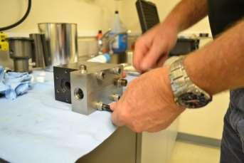
3 8000 Pump Removed From Enclosure

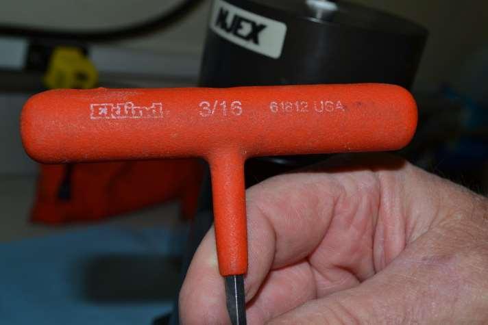
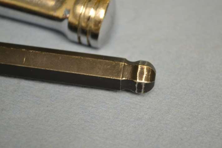
4 Special Tool Required: 1 Socket and 3/16 Long Tee Handled Ball End Allen
5
6

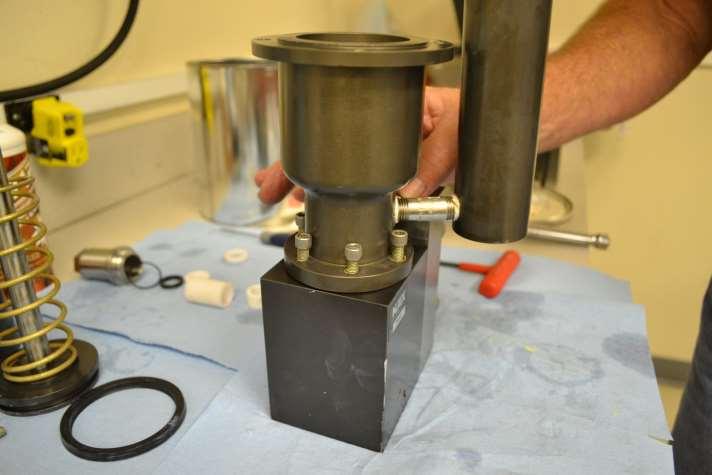
7 Remove Oil Cap

8 Oil Cap Removed

9 The Pump Should Have Oil In It To Be Removed

10 Place Paper Towels in Your Air Tight Waste Container

11 Pour Oil From The Pump Into Waste Container

12 Assure ALL Oil is Out

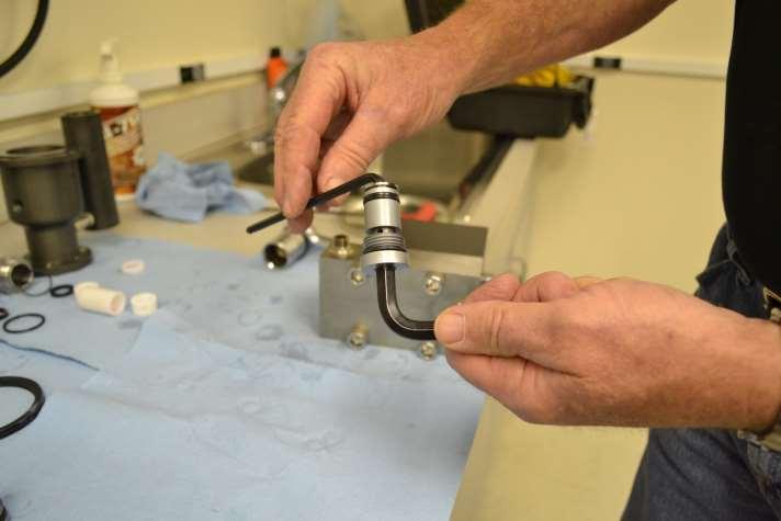
13 Remove the Allen Head Screws That Connect The Actuation Assy. to The Hydraulic Assembly

14 Note/Mark The Orientation Assemblies to Each Other

15 Separate The Two Assemblies

16 Remove The Plunger Seal and Support Sleeve

17 Sleeve and Seal Removed

18 Remove The Body O-Ring

19 Drain Any Remaining Oil Into Your Waste Container

20 Remove the Allen Screws That Attach the Actuation Cylinder

21 When Screws Are Removed, The Spring Will Force The Assy. Apart

22 Remove the Actuation Cylinder

23 Remove the Plunger Assy. and Spring

24 Plunger Assy. and Spring Removed

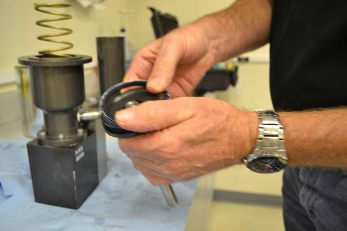
25 Prepare to Remove The Plunger Seal Cartridge

26 Using a 1 Socket Remove The Plunger Seal Cartridge

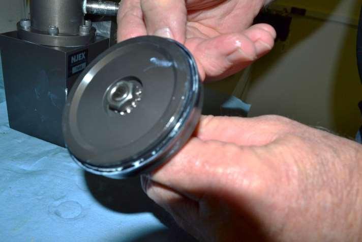
27 Cartridge Removed

28 Remove The Three (3) Bushings From The Cartridge

29 Bushings, Seal, and O-Ring Removed From Cartridge

30 Remove The U-Cup Actuation Seal

31 Remove the Bushing Stop From The Actuation Housing

32 Actuation and Plunger Parts Shown All Removed

33 Loosen The Outlet Check Assembly With 3/8 Allen

34 Outlet Check Assembly Removed

35 Remove The Outlet Check Assembly

36 Remove The Inlet Check Assy.

37 Inlet Check Assembly Removed

38 Inlet C.V. Outlet C.V
39 Disassemble Inlet C.V.
40
41
42 Notice Wafer Orientation
43

44 Dis-Assemble Discharge Check

45 After Removing the 1 st Wafer, Install the Bolt From Kit to Remove Sleeve

46 Remove Sleeve By Pulling on The Bolt Head While Holding The C.V, Body

47 Remove 2 nd C.V. Wafer

48 Lay Pump Body on It s Side
 Cap")
49 Loosen (4 ) Cap Screws

50 Turn Assy. Over and Remove Cap Screws

51 Hold Odorant Block Down While Removing Final Screw

52 Spring Will Separate Bodies

53 Bodies Separated

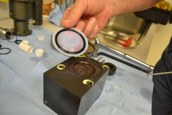
54 Remove O-Ring

55 Remove Diaphragm and O-rings
56

57 Prepare Parts Required to Re-Assemble

58 Prepare Parts Required to Re-Assemble


59 Assembly Lubricants Lubriplate 105 Assembly Lube Dow Corning Molykote 55

60 Use MolyKote to Lube and Retain O-Ring P/N A5-1143

61 Install O-Ring P/N A on Odorant Block

62 Lube O-Ring P/N A5-2226

63 Install O-Ring & Diaphragm in The Hydraulic Block

64 Diaphragm Installed

65 Install Diaphragm Piston

66 Install Spring

67 Place Odorant Block with it s O-Ring Attached Over The Spring

68 Press Blocks Together

69 Install Cap Screws by Hand

70 Tighten Cap Screws Progressively Using a Cross Tightening Pattern


71 Tighten Securely Utilizing Cross Tightening Pattern
72 Lube and Assemble The O-Rings and Back Up Rings on The Inlet C.V. Body

73 Install Wafer Notice Wafer Orientation

74 Install The Retainer

75 Tighten The Inlet C.V. Using Two Allen Wrenches

76 Install The Inlet C.V. Assembly

77 Tighten Inlet C.V. Assembly Securely

78 Re-Assemble The Outlet Check-Install 1 st Wafer (Rubber Side Facing You)

79 Install Sleeve with O- Ring

80 Press (Snap) Sleeve all the Way Down Using the Bolt From Kit
")
81 Install 2 nd Check Wafer (Rubber Side Facing You)

82 Install Seal Nut With O-Ring

83 Tighten Using TWO Allen Wrenches and Install O-Ring and Back Up Ring


84 Install The Outlet C.V. Assembly

85 Tighten The Outlet C.V. Assembly Securely

86 Prepare Lower Seal and Retainer for Assembly

87 Lubricate the Seal with Assembly Lube

88 Press Seal into the Retainer CAUTION Sharp Edge CAUTION Sharp Edge

89 Install Seal/Retainer Assy. in The Hydraulic Block

90 Lubricate the Retainer O-Ring P/N A5-2123

91 Install the O-Ring

92 Prepare to Reinstall the Actuation Housing

93 Align Housings to Original Orientation, and Install Screws
94

95 Tighten All Screws

96 Install the Stop Bushing

97 Stop Bushing Installed

98 Prepare Plunger Guide/Seal Assembly

99 Lubricate and Install The Seal

100 Press Seal ALL the Way into The Housing
101 Install One of The Short Bushings

102 Install The Long Bushing

103 Install The Second Short Bushing

104 Lube and Install The P/N A O-Ring

105 Install The Plunger Guide Assembly

106 Use 1 Socket to Tighten

107 Snug Tighten in Place DO NOT OVERTIGHTEN

108 Install The Spring

109 Lube and Install Actuation Seal on The Actuation Piston
110
111

112 Lubricate The Seal Fully

113 Install Piston/Plunger Assembly

114 Test Press the Piston Assembly Completely a Couple of Cycles

115 Angle Actuation Cylinder at 45 0 for Installation

116 Align for Correct Orientation

117 Press Down

118 Install Screws

119 Tighten Screws

120 Add NJEX Oil To The 1 st Thread in The Reservoir

121 Tilt the Pump Partially in Several Directions to Get The Trapped Air Out of The Hydraulic Block

122 Proper Oil Level After Air has Been Removed is Approximately Midway in The Reservoir

123 Replace The Oil Reservoir Cap

124 Lubricate and Replace External Connection O-Rings

125 External Connection O- Rings Replaced
126 Restart System Install Pump In System Close V-2, V-3 & V-5 Open V-4 Until Expansion Tank Pressure Reaches 25 psi. Open Odorant Supply Valve V15 or V17 as Equipped. Fill Verometer on Meter Level Window Prime Pump (V3) Open V6 & V8 Start The System Call if you need assistance.
D-04/G-04 Maintenance
 D-04/G-04 Maintenance NOTE: The numbers in parentheses are the Ref. Nos. on the illustrations in the Parts Manual. Daily Check the oil level and the condition of the oil. The oil level should be 1/4 in.
B14 AAA FINE FINISH SERIES PUMP OUTFIT
 PRODUCT INFORMATION B14 AAA FINE FINISH SERIES PUMP OUTFIT The B14 AAA pump system is an air assisted airless unit which combines airless and conventional or HVLP air atomization technologies to produce
B14 AAA FINE FINISH SERIES PUMP OUTFIT
 PRODUCT INFORMATION B14 AAA FINE FINISH SERIES PUMP OUTFIT The B14 AAA pump system is an air assisted airless unit which combines airless and conventional or HVLP air atomization technologies to produce
Cylinder Maintenance & Repair Instructions
 Cylinder Maintenance & Repair Instructions PENINSULAR CYLINDER CO. Model HP High Pressure Hydraulic Cylinders Proximity Switch & Non Proximity Switch Designs - High Pressure NFPA Hydraulic Cylinder ( 5,000
Vickers. Overhaul Manual. Vane Pumps. Small and Large Series Combination Pumps VC(K)(S)-**-(*)*D*-6(1) VC(K)(S)-**-(*)-*-*D*-5(1)
(S)-**-(*)*D*-6(1) VC(K)(S)-**-(*)-*-*D*-5(1)") Overhaul Manual Vickers Vane Pumps Small and Large Series Combination Pumps VC(K)(S)-**-(*)*D*-6(1) VC(K)(S)-**-(*)-*-*D*-5(1) Revised 12/1/86 I-3150-S Table of Contents Section I. Introduction................................................................................
Overhaul Manual Vickers Vane Pumps Small and Large Series Combination Pumps VC(K)(S)-**-(*)*D*-6(1) VC(K)(S)-**-(*)-*-*D*-5(1) Revised 12/1/86 I-3150-S Table of Contents Section I. Introduction................................................................................
D/G-10 Maintenance. Daily. Shutdown Procedure During Freezing Temperatures. Periodically
 D/G-10 Maintenance NOTE: The numbers in parentheses are the Reference Numbers on the exploded view illustrations found in this manual and in the Parts Manual. Daily Check oil level and condition of oil.
H2O-C14 AAA FINE FINISH SERIES PUMP OUTFIT
 PRODUCT INFORMATION H2O-C14 AAA FINE FINISH SERIES PUMP OUTFIT The H2O-C14 AAA pump system is an air assisted airless unit which combines airless and conventional or HVLP air atomization technologies to
RTX 2000 Thomas Compressor TG-550 Graco PN
 RTX 2000 Thomas Compressor TG-550 Graco PN 246888 Print of Complete Compressor--------------Page 2 Instruction for Kit 118628-------------------Page 3 Instruction for Kit 287845-------------------Page
I N S T R U C T I O N M A N U A L
 I N S T R U C T I O N M A N U A L M E T E R I N G P U M P S LINC84T-17, 18 & 20 Series Chemical Metering Pump Pneumatic Plunger T A B L E O F C O N T E N T S Contents - 84T-17, -18 & -20 Pump Manual...
6200 Series. Specifications. Fluid End Power End Models 6211, 6212, 6221, & 6222 Models 6241 & 6242 Part Material Part Material Part Material
 5.2018.12.i 6200 Series Specifications The Flomore 6200 Series Pump line consists of a series of basic pump options all developed from a modular power unit. All units are pneumatically driven positive
Powers Controls 656 Powermite Valve with 3-inch Top Rebuilding
 Powers Controls 656 Powermite Valve with 3-inch Top Rebuilding Technical Bulletin Document No. 155-240P25 TB 233 Description This Technical Bulletin describes the recommended method of rebuilding the 656
Rev. B Page 1 of 7 SPEC. ASSY INST, REMOTE ADJUSTABLE PRE-LOAD (30-25XX & SA XX)
") Page 1 of 7 SPEC. ASSY INST, REMOTE ADJUSTABLE PRE-LOAD (30-25XX & SA-5057-5XX) 19 3 10 11 4 7 20 16 14 15 12 13 21 5 9 6 17 2 1 Fig. 1 Reservoir Components Fig. 2 Housing Components 30-25XX & SA-5057-5XX
Page 1 of 7 SPEC. ASSY INST, REMOTE ADJUSTABLE PRE-LOAD (30-25XX & SA-5057-5XX) 19 3 10 11 4 7 20 16 14 15 12 13 21 5 9 6 17 2 1 Fig. 1 Reservoir Components Fig. 2 Housing Components 30-25XX & SA-5057-5XX
DR Series Radial Diaphragm Valves
 DR Series Radial Valves Service Instructions Valves with Plastic Actuators (1/2 through 1 inch) Valves with Aluminum Actuators (1/2 through 2 inch) Manual model Pneumatic model Manual model Pneumatic model
SINGLE ACTION FLUID PUMP
 SINGLE ACTION FLUID PUMP MODELS 4490, 4491, 4492 S SERIES A Model 4492 (Stub Pump) Model 4491 (250-275 Gal) Model 4490 (16-55 Gal) Model A52347R-248 (250-275 Gal NOV - 2006 Section -A6 Page -63A Table
F-20/G-20 Maintenance
 F-20/G-20 Maintenance NOTE: The numbers in parentheses are the Ref. Nos. on the illustrations in the Parts Manual. Periodically Change the oil after the first 100 hours of operation, and every 1000 operating
D/G-35 Maintenance. Shutdown Procedure During Freezing Temperatures. Daily. Periodically
 D/G-35 Maintenance NOTE: The numbers in parentheses are the Reference Numbers on the exploded view illustrations found later in this manual. Daily Check the oil level and the condition of the oil. The
Sachs shock manual. ( ) 2 & 4 Stroke RR Enduro. ( ) RS Dual Sport
 2 & 4 Stroke RR Enduro. ( ) RS Dual Sport") Sachs shock manual (2013 2015) 2 & 4 Stroke RR Enduro (2014-2015) RS Dual Sport 1 Introduction The procedures in this manual must take place in a clean environment using professional tools and some specific,
Sachs shock manual (2013 2015) 2 & 4 Stroke RR Enduro (2014-2015) RS Dual Sport 1 Introduction The procedures in this manual must take place in a clean environment using professional tools and some specific,
ANDERSON GREENWOOD SERIES 500 PILOT OPERATED SAFETY RELIEF VALVES INSTALLATION AND MAINTENANCE INSTRUCTIONS
 Before installation these instructions must be fully read and understood TABLE OF CONTENTS 1. General valve description and start-up... 1 2. Main valve maintenance... 1 3. Pilot maintenance... 5 4. Pilot
I N S T R U C T I O N M A N U A L
 I N S T R U C T I O N M A N U A L M E T E R I N G P U M P S LINC84T-13 Series Chemical Metering Pump Pneumatic Plunger T A B L E O F C O N T E N T S Contents - 84T-13 Pump Manual... Page General Specifications...
D/G-03 Maintenance. Shutdown Procedure During Freezing Temperatures. Daily. Periodically
 D/G-03 Maintenance NOTE: The numbers in parentheses are the Ref. Nos. on the illustrations in the Parts Manual. Daily Check the oil level and the condition of the oil. The oil level should be 3/4 in. (20
BRAKE E
 8-1 GENERAL...8-2 SPECIFICATIONS...8-6 COMPONENTS...8-7 FRONT BRAKE...8-12 DISASSEMBLY INSPECTION REASSEMBLY (Pn1, Cu2 3 TON SERIES)...8-12 DISASSEMBLY INSPECTION REASSEMBLY (Pn2 3 TON SERIES)...8-17 BRAKE
FRP SystemOne GELCOATER OPERATION MANUAL. MAGNUM VENUS PRODUCTS Operation Manual. Part No. M Revision
 1300-1-1 GELCOATER OPERATION MANUAL MAGNUM VENUS PRODUCTS Operation Manual Part No. M1300-1-1 Revision 04.26.01 Operation Manual Unit Information Unit # Type Of: Power Cylinder Metering Pump Gun Fluid
SERVICE PROCEDURES FOR CLUTCH HYDRAULIC UNITS
 SERVICE PROCEDURES FOR CLUTCH HYDRAULIC UNITS SAFETY PROCEDURES Always follow the vehicle manufacturer's recommended safety procedures in your Shop and Owners Manual. REQUIRED TOOLS Flat blade screwdriver,
FORK FREE PISTON MODIFICATION 2011 HONDA CRF250R
 217 Lorain Place Los Gatos, California 95032 408.406.2089 www.smartperformanceinc.com www.spi-racing.com FORK FREE PISTON MODIFICATION 2011 HONDA CRF250R WHAT? All production versions of the 2011 HONDA
JARVIS. Model HTC -80 Hog Toe Cutter
 Model HTC -80 Hog Toe Cutter HTC -80 Standard HTC -80 Pistol Grip EQUIPMENT SELECTION... Ordering No. HTC--80 Standard... 4025061 HTC--80 Pistol Grip... 4025100 HTC--80 Pistol Grip Long... 4025114 without
EP-2 Si Three-Piston Pump
 EP- Si Three-Piston Pump Customer Product Manual Issued 0/ For parts and technical support, call the Industrial Coating Systems Customer Support Center at (800) -99 or contact your local Nordson representative.
SERVICE PARTS LIST SPECIFY CATALOG NO. AND SERIAL NO. WHEN ORDERING PARTS 13 HP DIRECT DRIVE PRESSURE WASHER CATALOG NO
 SPECIFY CATALOG NO. AND SERIAL NO. WHEN ORDERING PARTS HP DIRECT DRIVE PRESSURE WASHER CATALOG NO. 555-22 SERVICE PARTS LIST STARTING SERIAL NUMBER B06A REVISED BULLETIN PAGE OF BULLETIN NO. 5-20-000 DATE
DP Series Diaphragm Valve Installation and Maintenance Instructions
 DP Series Diaphragm Valve Installation and Maintenance Instructions Contents Installation Actuation Actuator Orientation Welding Testing Maintenance Kit Contents Tool Requirements Exploded View Replacing
OPERATOR S MANUAL INCLUDING: OPERATION, INSTALLATION & MAINTENANCE RELEASED:
 OPERATOR S MANUAL 670042 INCLUDING: OPERATION, INSTALLATION & MAINTENANCE RELEASED: 1-25-07 REVISED: 8-27-08 (REV. 02) 1/2" DIAPHRAGM PUMP U.L. LISTED, 1:1 RATIO (METALLIC) READ THIS MANUAL CAREFULLY BEFORE
EP-2 Three-Piston Pump
 EP- Three-Piston Pump Customer Product Manual Issued 0/ For parts and technical support, call the Industrial Coating Systems Customer Support Center at (800) -99 or contact your local Nordson representative.
SD Bendix R-6 Relay Valve DESCRIPTION OPERATION
 SD-03-1060 Bendix R-6 Relay Valve SUPPLY PORT (RESERVOIR MOUNT TYPE) SERVICE PORT RETURN SPRING RELAY PISTON DELIVERY PORTS (4) SUPPLY PORT EXHAUST R-6 RELAY VALVE INSERT FIGURE 1 FIGURE 2 DESCRIPTION
Parts List. Item # Part # # Reqd. Description
 5.2017.6.f 1 3800 Series Injector 1 2 3 4 5 6 7 21 8 9 20 10 11 12 19 18 17 16 15 14 13 Parts List Item # Part # # Reqd. Description 1 A-0664 1 5 Gallon 430 Reservoir 2 A-0575 1 Thumb Screw 3 A-0172 1
Anti-Sway Bars Installation Instructions For Mazda MX-5 PART #
 Anti-Sway Bars Installation Instructions For 2006+ Mazda MX-5 PART # 920-330 Tools required: A jack and jack stands, 5mm Allen wrench, ratchet, 10mm, 12mm and 14mm, combination wrenches and sockets, 21mm
Anderson Greenwood Series 400 Piston Pilot POPRV Installation and Maintenance Instructions
 Before installation these instructions must be fully read and understood As capacity relief of the system is satisfied, system pressure will begin to decrease. When it does, the pilot will actuate and
Operating instructions Form no safety definitions
 Operating instructions Form no. 1000437 safety definitions safety symbols are used to identify any action or lack of action that can cause personal injury. Your reading and understanding of these safety
Flexplate Conversion Installation Instructions
 Flexplate Conversion Installation Instructions For all Wagner units using Clark 8000 torque converter. Use the following instructions for modifying your ring gear torque converter to a fl explate torque
MAINTENANCE PROCEDURE FOR MK18/MK16
 MAINTENANCE PROCEDURE FOR MK18/MK16 MK16/MK18-1/1- MAINTENANCE PROCEDURE FOR MK 16 / 18 1 ST STAGES WARNING: this maintenance procedure is only for appointed Scubapro technicians that followed a complete
Cylinder and Valve: AirHawk II Air Mask
 Cylinder and Valve: AirHawk II Air Mask MAINTENANCE AND REPAIR MSA 011 (L) Rev. 0 MSA 2010 Prnt. Spec. 10000005389(I) Mat. 10104218 Doc. 10104218 Parts List Cylinder Replacement Kits Item P/N Description
Paint/Solvent/Dump Valve and Flow-Through Valve
 Instruction Sheet P/N 08573D Paint/Solvent/Dump Valve and Flow-Through Valve. Description See Figure. The paint/solvent/dump valve is a normally-closed valve that opens to trigger and/or dump coating material.
AIRGO MISTING SYSTEM MAINTENANCE
 AIRGO MISTING SYSTEM MAINTENANCE WARNING: Disconnect the fan and misting pump from power before servicing. Service schedule Schedule Procedure 50 hours of operation Initial oil change 300 hours of operation,500
SD Bendix MV-3 Dash Control Module DESCRIPTION. Bottom View
 SD-03-3415 Bendix MV-3 Dash Control Module MOUNTING PLATE MOUNTING HOLES (4) Dual Circuit SUPPLY Check VALVE AUXILIARY PORT (Optional) delivery DESCRIPTION secondary supply Trailer delivery FIGURE 1 -
CAB TILT HYDRAULIC SYSTEM
 OPERATION, MAINTENANCE and SERVICE INSTRUCTIONS CAB TILT HYDRAULIC SYSTEM WITH POWER-PACKER PUMP, CYLINDERS and LATCHES A division of Actuant Corporation 1-800-745-4142 1 www.powerpackerus.com Notice The
MM Rear Coil-Over Kit - Bilstein Shocks (MMCO-3)
") 3430 Sacramento Dr., Unit D San Luis Obispo, CA 93401 Telephone: 805/544-8748 Fax: 805/544-8645 www.maximummotorsports.com MM Rear Coil-Over Kit - Bilstein Shocks (MMCO-3) Read all instructions before
3430 Sacramento Dr., Unit D San Luis Obispo, CA 93401 Telephone: 805/544-8748 Fax: 805/544-8645 www.maximummotorsports.com MM Rear Coil-Over Kit - Bilstein Shocks (MMCO-3) Read all instructions before
Service Manual Air Tech Second Stage
 Service Manual Air Tech Second Stage Copyright 2002, Cressi-sub Revised 3/2002 2 Air Tech Second Stage Service Manual Contents BEFORE STARTING... 3 DISASSEMBLY... 3 PARTS CLEANING AND LUBRICATION... 9
I N S T R U C T I O N M A N U A L
 I N S T R U C T I O N M A N U A L M E T E R I N G P U M P S LINC84T-10, 11, 12, & 14 Series Chemical Metering Pump Pneumatic Plunger Contents - 84T-10, 11, 12, & 14 Pump Manual... Page General Specifications...
Sachs 48mm Closed Cartridge fork Service Manual
 Sachs 48mm Closed Cartridge fork Service Manual 1 Fork seal driver 2 Special soft jaws 3 Fork cap wrench 4 Rebound rod holding tool 5 Compression assembly holding tool 6 Retaining clip tool Special Tools
JARVIS. Model 30CL-ABC Beef Aitch Bone Cutter
 Model 30CL-ABC Beef Aitch Bone Cutter EQUIPMENT SELECTION... Ordering No. TABLE OF CONTENTS... Page 30CL--ABC Aitch Bone Cutter Front Entry... 4025102 Rear Entry... 4025111 Hydraulic Power Unit... 4027266
INSTALLATION INSTRUCTIONS FOR THE TRUCK MOUNTED VIPER ADDITIVE INJECTION SYSTEM GTP-8776C
 INSTALLATION INSTRUCTIONS FOR THE TRUCK MOUNTED VIPER ADDITIVE INJECTION SYSTEM GTP-8776C This additive injection system was designed to be used with five gallon jug of additive. The system is supplied
TECHNICAL DATA 1-1/2 (dn40)
") July 1, 2011 Deluge Valves 209a DESCRIPTION The Viking Model E-3 1-1/2 Deluge Valve is a quick-opening, differential type flood valve with a rolling diaphragm clapper. The deluge valve is used to control
July 1, 2011 Deluge Valves 209a DESCRIPTION The Viking Model E-3 1-1/2 Deluge Valve is a quick-opening, differential type flood valve with a rolling diaphragm clapper. The deluge valve is used to control
Air Actuated Hydraulic Bottle Jacks
 Air Actuated Hydraulic Bottle Jacks Operating Instructions & Parts Manual Model Number Atd-7412 Atd-7420 Capacity 12 Ton 20 Ton Atd Tools Inc. 160 Enterprise Drive, Wentzville MO 63385 Printed in China
Series 3900/M Pump Retrofit Kit
 Instruction Sheet P/N Series 900/M Pump Retrofit Kit WARNING: Allow only qualified personnel to perform the following tasks. Observe and follow the safety instructions in this document and all other related
D-15/G-15 Maintenance
 D-15/G-15 Maintenance NOTE: The numbers in parentheses are the Reference Numbers on the exploded view illustrations found later in this manual and in the Parts Manual. Daily Check the oil level and the
MAINTENANCE PROCEDURE FOR MK17
 MAINTENANCE PROCEDURE FOR MK17 MK17 25. juli 2005-1/5 MAINTENANCE PROCEDURE FOR MK 17 1ST STAGE WARNING: this maintenance procedure is only for appointed Scubapro technicians that followed a complete course
3/4" DIAPHRAGM PUMP 1:1 RATIO (NON-METALLIC) READ THIS MANUAL CAREFULLY BEFORE INSTALLING, OPERATING OR SERVICING THIS EQUIPMENT.
 READ THIS MANUAL CAREFULLY BEFORE INSTALLING, OPERATING OR SERVICING THIS EQUIPMENT.") OPERATOR S MANUAL PD07P-X-X INCLUDING: OPERATION, INSTALLATION & MAINTENANCE RELEASED: 11-30-06 REVISED: (REV. 01) 3/4" DIAPHRAGM PUMP 1:1 RATIO (NON-METALLIC) READ THIS MANUAL CAREFULLY BEFORE INSTALLING,
OPERATOR S MANUAL PD07P-X-X INCLUDING: OPERATION, INSTALLATION & MAINTENANCE RELEASED: 11-30-06 REVISED: (REV. 01) 3/4" DIAPHRAGM PUMP 1:1 RATIO (NON-METALLIC) READ THIS MANUAL CAREFULLY BEFORE INSTALLING,
TECHNICAL DATA. Q= C v P S
 1 of 9 1. DESCRIPTION The Viking Model E-1 Deluge Valve is a quick-opening, differential diaphragm, flood valve with one moving part. The deluge valve is used to control water flow in deluge and preaction
Air-Assist Service Jack Max. Capacity: 10 Tons
 Form No. 565786 Parts List & Operating Instructions for: 1511B Air-Assist Service Jack Max. Capacity: 10 Tons 109 67 66 68 77 69 70 78 95 94 107 106 108 26 71 72 72 93 X L 65 75 92 91 90 89 88 87 86 85
AF0465-XX SERVICE KITS GENERAL DESCRIPTION MODEL DESCRIPTION CHART OPERATING AND SAFETY PRECAUTIONS THIS MANUAL COVERS THE FOLLOWING MODELS
 OPERATOR S MANUAL INCLUDING: SERVICE KITS, TROUBLESHOOTING, PARTS LIST, DISASSEMBLY & REASSEMBLY. 4-1/4 AIR MOTORS AF044X-XX (4 STROKE) and AF046X-XX (6 STROKE) Also covers 637489 service kits AF044X-XX
Hydraulic Transmission Jack, Telescopic
 Operating Instructions & Parts Manual Hydraulic Transmission Jack, Telescopic Model 4000 400 (Air Operated) Capacity 000 lbs. 000 lbs. Model 4000 Model 400 U.S. Patent No. 6,02,377! This is the safety
AS-Interface Installation Manual. ASAHI / AMERICA, Inc. Thermoplastic Valves and Piping Systems
 AS-Interface Installation Manual Page 1 of 9 Rev A April 16, 2003 ASAHI / AMERICA, Inc. Thermoplastic Valves and Piping Systems 35 GREEN STREET PO BOX 653 MALDEN, MA. 02148 AS-Interface Installation Manual
Model 8329 Table of Contents
 SERVICE & OPERATING MANUAL Original Instructions Instructions Sheet: 670991 Model 8329 Table of Contents Engineering Data and Temperature Limitations... 1 Performance Curve... 2 Dimensions... 3 Metric
Instrument Pressure Range Standard Body psi max. High Flow Rate Body psi max.
 Basic Information All ESP Types Overall Size Length............................ 12 3/4-in. Max. Diameter All Piston Type...................... 2 1/4-in. Max. 2-in. Diaphragm..................... 2 7/8-in.
OPERATOR S MANUAL AND SALES AND ENGINEERING DATA
 OPERATOR S MANUAL AND SALES AND ENGINEERING DATA INCLUDING: SPECIFICATIONS, SERVICE KITS, GENERAL INFORMATION, PARTS, TROUBLESHOOTING. INCLUDE MANUALS: AF044X-XX Air Motor (pn 97999-1466) & S-632 General
BETTIS ACTUATOR & CONTROLS SERVICE INSTRUCTIONS FIELD CONVERSION OF SPRING CARTRIDGE FAIL DIRECTION CLOCKWISE TO COUNTER-CLOCKWISE OR THE INVERSE
 BETTIS ACTUATOR & CONTROLS SERVICE INSTRUCTIONS FIELD CONVERSION OF SPRING CARTRIDGE FAIL DIRECTION CLOCKWISE TO COUNTER-CLOCKWISE OR THE INVERSE FOR THE FOLLOWING SERIES T3XX-SRX AND T4XX-SRX SPRING RETURN
TRIM AND TILT TABLE OF CONTENTS TRIM AND TILT
 TRIM AND TILT TABLE OF CONTENTS SERVICE CHART................................................................... 326 SYSTEM DESCRIPTION............................................................. 328
Model Ton Hand Carry Axle Jack P/N: CJ67D0250-1
 Model 1504-50 15 Ton Hand Carry Axle Jack P/N: CJ67D0250-1 Operation and Maintenance Manual with Illustrated Parts List 2222 South Third Street Columbus, Ohio 43207-2402 Phone (614) 443-7492 FAX (614)
1 HIGH PRESSURE DIAPHRAGM PUMP 3:1 RATIO (METALLIC)
") OPERATOR S MANUAL INCLUDING: OPERATION, INSTALLATION & SERVICE 1 HIGH PRESSURE DIAPHRAGM PUMP 3:1 RATIO (METALLIC) RELEASED: 7-7-00 REVISED: 3-2-06 (REV. H) READ THIS MANUAL CAREFULLY BEFORE INSTALLING,
OPERATOR S MANUAL INCLUDING: OPERATION, INSTALLATION & SERVICE 1 HIGH PRESSURE DIAPHRAGM PUMP 3:1 RATIO (METALLIC) RELEASED: 7-7-00 REVISED: 3-2-06 (REV. H) READ THIS MANUAL CAREFULLY BEFORE INSTALLING,
PLEASE READ ALL INSTRUCTIONS BEFORE INSTALLATION
 18 March 2010 1994-02 Dodge 4WD Steering Box Support (SBS) 1 BD Steering Box Support (SBS) 1994-2002 2500-3500 4x4 1994-2001 1500 4x4 P/N# 1032004 PLEASE READ ALL INSTRUCTIONS BEFORE INSTALLATION 18 March
series5000 GAS/PNEUMATIC DRIVEN INJECTION PUMP TEXSTEAM Pumps DESCRIPTION APPLICATIONS
 TEXSTEAM Pumps series5000 GAS/PNEUMATIC DRIVEN INJECTION PUMP DESCRIPTION Texsteam Series 5000 chemical injectors are positive displacement units powered by integral gas/air motor. These pumps fill the
SERVICE KITS PUMP DATA MODEL DESCRIPTION CHART INCLUDING: OPERATION, INSTALLATION & MAINTENANCE RELEASED:
 OPERATOR S MANUAL PD07P-X-X INCLUDING: OPERATION, INSTALLATION & MAINTENANCE RELEASED: 2-16-07 REVISED: 7-15-16 (REV. H) 3/4" DIAPHRAGM PUMP 1:1 RATIO (NON-METALLIC) READ THIS MANUAL CAREFULLY BEFORE INSTALLING,
3/4" DIAPHRAGM PUMP SERVICE KITS PUMP DATA MODEL DESCRIPTION CHART PD07R - X A S - X X X
 OPERATOR S MANUAL PD07X-X-X INCLUDING: OPERATION, INSTALLATION & MAINTENANCE RELEASED: 2-20-07 REVISED: 5-21-10 (REV. 04) 3/4" DIAPHRAGM PUMP 1:1 RATIO (METALLIC) READ THIS MANUAL CAREFULLY BEFORE INSTALLING,
Air / Hydraulic Under Axle Jack
 655 Eisenhower Drive Owatonna, MN 55060-0995 USA Phone: (507) 455-7000 Tech. Serv.: (800) 533-6127 Fax: (800) 955-8329 Order Entry: (800) 533-6127 Fax: (800) 283-8665 International Sales: (507) 455-7223
Service Manual Air Plus Second Stage
 Service Manual Air Plus Second Stage Includes XS Series Second Stage Copyright 2002, Cressi-sub Revised 3/2002 2 Air Plus Second Stage Service Manual Contents BEFORE STARTING... 3 DISASSEMBLY... 3 PARTS
X-Trainer 43mm fork service manual. Beta USA, Inc This work should be performed by a trained motorcycle technician.
 X-Trainer 43mm fork service manual Beta USA, Inc. 2016 This work should be performed by a trained motorcycle technician. Table of contents Page Introduction/special tools... 2 Fork exploded view... 3 Legend.
JARVIS. Model 30CL-1 and 30CL-3 Hock Cutter and Dehorner
 Model 30CL-1 and 30CL-3 Hock Cutter and Dehorner 30CL--1 Hock Cutter 30CL--1 Pistol Grip 30CL--3 Dehorner EQUIPMENT SELECTION... Ordering No. 30CL--1 Hock Cutter... 4025013 30CL--1 Hock Cutter with Grabber
Installation Vertical Pump: Installation 'CM' and 'CDM' Style: Operation:
 Installation Vertical Pump: Gusher vertical end suction pumps with integral shaft is easily installed and put into service. With the one piece shaft design there is no couplings to align, no shims or no
INSTALLATION GUIDE. RMS510, 511, 512, 513, 511MC 510-OR, 512-OR Manual Revision:
 REKLUSE MOTOR SPORTS z-start Dual-Actuated Brake Kit INSTALLATION GUIDE RMS510, 511, 512, 513, 511MC 510-OR, 512-OR 196-210 Manual Revision: 051309 2002-2009 Rekluse Motor Sports Rekluse Motor Sports,
Hydraulics. Part B, Section 1. This section covers the following unit configurations. 3700V 3800V 3900V
 Part B, Section 1 Model Voltage Pump Manifold Control This section covers the following unit configurations. 3500V 3700V 3800V 3900V All Piston (F) 4-Port (A) 6-Port (B or C) -Port (S or T) Vista Standard
WARNING Carefully Read These Instructions Before Use
 DO NOT RETURN THIS SPRAYER TO STORE Call: 1-800-950-4458 Backpack Sprayer Use and Care Manual Manufactured for Northern Tool + Equipment Co., Inc. WARNING Carefully Read These Instructions Before Use Model
OPERATION MANUAL NT50 NOMAD TRANS-FLO AIR-OPERATED DOUBLE DIAPHRAGM PUMPS. A JDA Global Company. 7/11 rev. 1
 OPERATION MANUAL NT50 NOMAD TRANS-FLO AIR-OPERATED DOUBLE DIAPHRAGM PUMPS A JDA Global Company 7/11 rev. 1 CAUTION SAFETY POINTS TEMPERATURE LIMITS: Neoprene -17.8 C to 93.3 C 0 F to 200 F Buna-N -12.2
Armstrong Double Duty 6 Steam Trap/Pump Combination Installation and Maintenance
 Armstrong Double Duty 6 Steam Trap/Pump Combination Installation and Maintenance 119 Overview Warning: This bulletin should be used by experienced personnel as a guide to the installation and maintenance
Escape Cylinder and Valve
 Escape Cylinder and Valve MAINTENANCE AND REPAIR TAL 1601 (L) Rev. 2 MSA 2016 Prnt. Spec. 10000005389 (I) Mat. 10064389 Doc. 10064389 CYLINDER COMPONENTS Item Part No. Description 818159 5 Minute, Aluminum
Maverick American 3085 Bluff Street Boulder, CO Tel: Fax: ML7.2 SHOCK SERVICE MANUAL
 Maverick American 3085 Bluff Street Boulder, CO 80301 Tel: 303-415-0370 Fax: 303-415-0676 www.maverickamerican.com ML7.2 SHOCK SERVICE MANUAL 1. OVERVIEW 1.1. The Maverick ML7.2 rear shock is an oil damped
LZS8WS EZH2O BOTTLE FILLING STATION & COOLER
 INSTALLATION, CARE & USE MANUAL TM LZS8WS EZH2O BOTTLE FILLING STATION & COOLER IMPORTANT THIS IS AN INDOOR APPLICATION ONLY. ALL SERVICE TO BE PERFORMED BY AN AUTHORIZED SERVICE PERSON. TOOLS REQUIRED
Maintenance Manual Reduced Pressure Assembly Models 860 & 880V 2 1 /2" 10"
 IOM-F-860_880V INSTALLATION, OPERATION, MAINTENANCE Maintenance Manual Reduced Pressure Assembly Models 860 & 880V 2 1 /2" 10" 860 880V Standard Configuration 880V Vertical Configuration INDEX Vandalism..............................................
SAFETY RELATED MANDATORY OUTRIGGER CYLINDER INSPECTION AND REPAIR
 An ISO 9001 Registered Company June 10, 1999 SERVICE BULLETIN SL-158 This Service Bulletin should be read and understood by all Service Technicians who are trained to service the units affected by this
Circulation Kits for CP Pumps
 Instruction Sheet P/N 08000C Description This instruction sheet covers two circulation kits for CP Pumps: Stainless steel circulation kit, with Viton O-rings Stainless steel circulation kit, with EPR O-rings
SR 55 POWER STEERING GEAR. POWER STEERING GEAR REMOVAL AND INSTALLATION Remove and install the parts, as shown.
 STEERING SR55 GEAR GEAR REMOVAL AND INSTALLATION Remove and install the parts, as shown. SR56 STEERING MAIN POINT OF REMOVAL AND INSTALLATION 1. REMOVE OIL RESERVOIR 2. REMOVE AIR CLEANER ASSEMBLY 3. DISCONNECT
High Turn Down Valve Model SF10000HTD Operations and Maintenance Manual. P.O. BOX 1728 Woodinville, WA USA FAX 425.
 High Turn Down Valve Model SF0000HTD Operations and Maintenance Manual WWW.SKOFLO.COM P.O. BOX 78 Woodinville, WA 9807 USA 45.485.786 FAX 45.368-696 PRINCIPLE OF OPERATION: SkoFlo high turn down valves
Model No. 668D3. COFFEPUMP Part No Product Code: O/C GJAN21.DB6B-DC310B
 Model No. 668D3 COFFEPUMP Part No. 9168 Product Code: O/C GJAN21.DB6B-DC310B OVERHAUL MANUAL with ILLUSTRATED PARTS LIST Page 1 of 15 P/N 5914 Rev D 01/17/05 1.0 Introduction 1.1 Description 1.1.1 The
3 Inch & 4 Inch Digital Bypass Pressure Control Valves
 SM64505 September 2008 Aerospace Group Conveyance Systems Division Carter Brand Ground Fueling Applicable addition manuals: None Maintenance & Repair Manual 3 Inch & 4 Inch Digital Bypass Pressure Control
Step by Step Assembly Instructions
 SF10000 NMFA Body Assembly Body, PN 20673 Seat, PN 20275 Seat "O" Ring, Seat BU Ring, Seat Retainer, P/N 20528 Snap Ring, P/N 71002969 Base Cap, PN 20282 Base Cap "O" Ring, Base Cap BU Ring, M8 X 1.25
INSTALLATION, OPERATION, AND MAINTENANCE MANUAL WELKER INJECTION PUMP
 INSTALLATION, OPERATION, AND MAINTENANCE MANUAL WELKER INJECTION PUMP MODEL SSO-8 DRAWING NUMBERS AD148CF AD148CG AD148CO AD148CQ AD500CA MANUAL NUMBER IOM-065 REVISION Rev. A, 8/17/2016 TABLE OF CONTENTS
SD Bendix E-10PR Retarder Control Brake Valve DESCRIPTION. OPERATION - Refer to Figure 2
 SD-03-832 Bendix E-10PR Retarder Control Brake Valve MOUNTING PLATE SUPPLY 4 PORTS ELECTRICAL AUXILIARY DESCRIPTION TREADLE RETARDER CONTROL SECTION EXHAUST DELIVERY 4 PORTS FIGURE 1 - E-10PR RETARDER
Halsey Taylor Owners Manual
 Halsey Taylor Owners Manual Fully-Recessed Barrier-Free Water Cooler RC RC W/CUP DISPENSER INSTALLER To assure you install these models easily and correctly, PLEASE READ THESE SIMPLE INSTRUCTIONS BEFORE
Repair Parts Sheet Turbo II Air Hydraulic Pump Model 10500, 10502, (AHP-15T, AHP-25TP, AHP-35T))
)") Repair Parts Sheet Turbo II Air Hydraulic Pump Model 10500, 10502, 10504 (AHP-15T, AHP-25TP, AHP-35T)) Rev. 0506 Install all kit components to insure optimum performance of the repaired unit. NOTE: Storing
Repair Parts Sheet Turbo II Air Hydraulic Pump Model 10500, 10502, 10504 (AHP-15T, AHP-25TP, AHP-35T)) Rev. 0506 Install all kit components to insure optimum performance of the repaired unit. NOTE: Storing
Anderson Greenwood Series 800 POSRV Installation and Maintenance Instructions
 Before installation these instructions must be fully read and understood Table of contents 1. General valve description and start-up... 1 2. Main valve maintenance... 2 3. Pilot maintenance... 6 4. Pilot
Maverick American 3085 Bluff Street Boulder, CO Tel: Fax: ML7.0 SHOCK SERVICE MANUAL
 Maverick American 3085 Bluff Street Boulder, CO 80301 Tel: 303-415-0370 Fax: 303-415-0676 www.maverickamerican.com ML7.0 SHOCK SERVICE MANUAL 1. OVERVIEW 1.1. The Maverick ML7.0 rear shock is an oil damped
BD Steering Box Support (SBS) Dodge Cummins
 Dodge Cummins") 1 BD Steering Box Support (SBS) 2003-2009 Dodge Cummins P/N# 1032005 1032006 2003-2008 4WD 2009 4WD PLEASE READ ALL INSTRUCTIONS BEFORE INSTALLATION This part does not fit the POWERWAGON model. KIT CONTENTS:
1 BD Steering Box Support (SBS) 2003-2009 Dodge Cummins P/N# 1032005 1032006 2003-2008 4WD 2009 4WD PLEASE READ ALL INSTRUCTIONS BEFORE INSTALLATION This part does not fit the POWERWAGON model. KIT CONTENTS:
HYDRAULICS. TX420 & & lower. Hydraulic Tandem Pump Removal. 4. Remove the LH side panel (Fig. 0388).
.") TX420 & 425 240000299 & lower 4. Remove the LH side panel (Fig. 0388). Hydraulic Tandem Pump Removal Note: Cleanliness is a key factor in a successful repair of any hydraulic system. Thoroughly clean all
TX420 & 425 240000299 & lower 4. Remove the LH side panel (Fig. 0388). Hydraulic Tandem Pump Removal Note: Cleanliness is a key factor in a successful repair of any hydraulic system. Thoroughly clean all
Models & Inch & 4 Inch Digital Inline Pressure Control Valves SM64504
 SM64504 September 2008 Aerospace Group Conveyance Systems Division Carter Brand Ground Fueling Equipment Applicable addition manuals: None Maintenance & Repair Manual 3 Inch & 4 Inch Digital Inline Pressure