Ampco ZP3 Series (Addendum) Positive Displacement Pumps Installation and Maintenance Manual
|
|
|
- Avice Lindsey
- 5 years ago
- Views:
Transcription


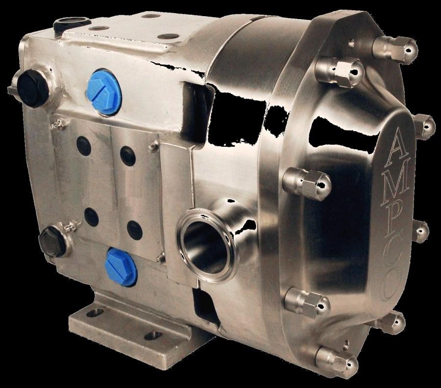

1 Ampco ZP3 Series (Addendum) Positive Displacement Pumps Installation and Maintenance Manual

2 Pump Disassembly 1) Start by removing the cover nuts with an appropriate wrench (Figure 1). During disassembly place all parts on a clean, protected surface with finished surfaces and seal faces facing up. Tap the cover off using a soft mallet. Remove the cover o-ring and inspect it. Figure 1: Removing ZP3 Cover 2) Loosen each rotor nut using the appropriate size wrench and a non-metallic wedge to keep the rotors from moving (Figure 2). Unthread each nut and disassembly the nut assembly (Rotor nut, Bellville washer and retaining o-ring). Rotor Nut Assembly Wedge Figure 2: Rotor Removal Bellville Washer Retaining O-ring Rotor Nut 3) Remove the rotors by orientating them perpendicular to each other and then pulling them out. It is important to be cautious with the rotors so that they are not damaged in any way. If rotors are difficult to remove, use a nylon or wood lever to pry them out without damaging the body or the rotors. Use Figure 3 to ensure that all parts are removed. Part Rotor Nut Assembly 2 Rotor Nut O-ring 3 ZP3 Rotor 4 Rotating Seal O-ring 5 Rotating Seal 6 Stationary Seal 7 Stationary Seal O-ring 8 Wave Spring Figure 3: Exploded View Page 2 November 2011
. Insert a rotor key in the keyway on the shaft.")
. Align the slots on the stationary seal with the pins inside the hub.")

 Next install the rotating o-ring onto the rotating seal by stretching it (not rolling) onto")
3 Seal Assembly 1) Start by inserting the wave spring into the sleeve making sure that it sets below the stationary drive pins (Figure 4). Insert a rotor key in the keyway on the shaft. Wave Spring 2) Slide the stationary seal o-ring into the body hub until it seats against the top of the sleeve (previously installed). Align the slots on the stationary seal with the pins inside the hub. Press the stationary seal into the hub until is seats on the spring; there should be noticeable spring resistance when pushing on the seal. Align the slot and pin Figure 4: Inserting Spring Stationary Seal O-ring Figure 5: Stationary Seal Assembly 3) Next install the rotating o-ring onto the rotating seal by stretching it (not rolling) onto the rotating seal (Figure 6). 1 2 Figure 6: Installing the Rotating O-ring November 2011 Page 3
 Slide the rotors on to the shafts until they seat against the shaft shoulder (Figure 8).")
4 Pump Assembly 4) Slide the rotating seal onto the rotor hub (Figure 7) making sure to align the slots on the seal to the drive pins in the rotor. Press the seal down until it seats inside of the rotor. Rotating Seal O-ring Rotating Seal Align 5) Slide the rotors on to the shafts until they seat against the shaft shoulder (Figure 8). Shoulder Figure 7: Inserting Rotating O-ring Figure 8: Rotor Assembly 6) Install the Bellville washers in the rotor nuts in the orientation shown and hold them in place using the small retaining o-rings (Figure 9). Install a rotor nut o-ring before threading the nut onto the shaft. Retaining O-ring Rotor Nut O-ring Bellville Washer Rotor Nut Figure 9: Rotor Nut Assembly Page 4 November 2011
 of force.")
5 Seal Assembly 7) Thread the nut onto the shaft and tightening it down using the appropriate wrench and a non-metallic wedge to hold the rotor in place (Figure 10). Torque the rotor nuts down using 163 N-m (ZP3 30, See ZP2 manual for correct values) of force. Orientate the rotors as seen in Figure 10 and Always tighten the first rotor positioned under the overlap of the opposing rotor. Repeat with the second rotor in the same orientation. Wedge Overlap Figure 10: Rotor Assembly 8) Install a new cover o-ring and slide the cover over the studs making sure that the dowels in the body are aligned with the correct dowel holes in the cover (Figure 11). Visually inspect to ensure that the cover o-ring remained in place. Turn the cover nuts (clockwise) by hand and fully tighten them using the appropriate wrench. Tighten the rotor nuts in an opposing manner, as seen on Figure 11, so that the cover is evenly tightened to the body. Figure 11: Cover Assembly November 2011 Page 5


 A (Backface Clearance)")
6 Pump Clearances The performance of a ZP3 is based on the tight clearances between the pump body and the rotors. These clearances are critical to ensure the pump performs up to the system requirements. The clearance between the rotor and the back face of the body is referred to as the backface clearance. Other clearances are shown in Figure 12 and should be in accordance to Table 1. Use shims and a depth micrometer to measure the clearances. A (Backface Clearance) C (Front Face Clearance) B (Rotor to Body Clearance) Measuring A Measuring B Measuring C Depth Mic. Cutaway Note: For non-standard rotors contact Ampco Figure 12: Critical Pump Clearances Table 1: Critical Pump Clearance Dimensions (Standard Rotors) A (Backface Clearance) B (Rotor to Body Clearance) C (Front Face Clearance) ZP3 Model Inch mm Inch mm Inch mm 6, 15, , , 60, 64, , , 220, , Page 6 November 2011
.")
 and inspect the gears for wear and damage (Figure 22, B). Also check for backlash and looseness.")
7 Annual Maintenance It is important to perform an annual maintenance check of the pump in addition to the preventative maintenance procedures listed on pages 13 and 14. Annual maintenance practices are as follows: Check the gear case bearings by measuring the shaft s radial movement with a dial indicator (Figure 22, A). If the movement is greater than or equal to the rotor-to-body clearance found on page 28 (Table 8) the bearings should be replaced. Remove the gear casing cover (See page 21 for disassembly information) and inspect the gears for wear and damage (Figure 22, B). Also check for backlash and looseness. Inspect the rotors for signs of wear and stress cracks around the areas defined in Figure 22, C. Replace, if necessary. Check the pump clearances detailed on page 28 to determine pump wear. Pump wear can be compensated by increasing pump speed. Check Bearings Check Gears Check A B C Figure 22: Annual Maintenance Checks Cleaning All wetted parts are designed and manufactured to be acceptable by 3A Sanitary Standards. The body, rotors, and seals can be easily disassembled and cleaned simply by removing the cover and rotor nuts. Pump disassembly information begins on page (ZP2 Manual page16). The ZP3 pumps is clean-in-place (CIP) capable allowing CIP solution to reach all surfaces inside the pump. The fluid velocity (typically 5 ft/sec) and differential pressure (30 psi recommended) are critical components of a correct CIP setup. For additional support, please contact the Engineering Department at ( ). November 2011 Page 7
8 2045 W. Mill Road Glendale, WI Phone: (800) or (414) Fax: (414) For additional information on the ZP3 series and other Ampco Pumps products, please visit our website: Revision Date: November 2011
Ampco ZP1 Series. Positive Displacement Pumps Installation and Maintenance Manual
 Ampco ZP1 Series Positive Displacement Pumps Installation and Maintenance Manual Table of Contents Introduction... 3 Introduction... 3 Ampco Pump Company Warranty... 3 General Information... 3 Shipping
THE BEST SOLUTION FOR YOUR SANITARY PROCESSES
 THE BEST SOLUTION FOR YOUR SANITARY PROCESSES ZP3 Series Installation and Maintenance Manual Q-Pumps 1 Table of Contents Introduction... 3 Introduction... 3 General Information... 3 Shipping Damage or
THE BEST SOLUTION FOR YOUR SANITARY PROCESSES. ZP2 Series. Installation and Maintenance Manual
 THE BEST SOLUTION FOR YOUR SANITARY PROCESSES ZP2 Series Installation and Maintenance Manual Table of Contents Introduction... 3 Introduction... 3 General Information... 3 Shipping Damage or Loss... 3
ZP SERIES POSITIVE DISPLACEMENT PUMPS
 ZP SERIES POSITIVE DISPLACEMENT PUMPS ZP Series Pumps REDEFINING ENGINEERED EXCELLENCE The ZP Series establishes a new standard of value, quality and features in the positive displacement pump market.
INSTRUCTION AND MAINTENANCE MANUAL: FKL-25, 50, 75, 150, 250 and 400 Style Pump
 FKL Series Pump INSTRUCTION AND MAINTENANCE MANUAL: FKL-5, 50, 75, 150, 50 and 400 Style Pump SANITARY POSITIVE DISPLACEMENT PUMP Fristam Pumps Description This manual contains installation, operation
Boston Gear LOR Series
 Boston Gear LOR Series Trig-O-Matic Lite Overload Release Clutch Installation and Maintenance Instructions Doc. No. LOR Series Trig-O-Matic Lite www.bostongear.com LOR SERIES TRIG-O-MATIC LITE OVERLOAD
INSTRUCTION AND MAINTENANCE MANUAL:
 1 INSTRUCTION AND MAINTENANCE MANUAL: FKL Positive Displacement Pump Models (original design, pre-2011): 25, 50, 75, 150, 205, 250 Models (original design, pre-2015): 400 Models: 580, 600 SANITARY POSITIVE
INSTRUCTION AND MAINTENANCE MANUAL: FL2/FL3 Series Pumps (Models: 15, 58, 75, 100 & 130)
") FL Series Pump INSTRUCTION AND MAINTENANCE MANUAL: FL/FL3 Series Pumps (Models: 5, 58, 75, 00 & 30) SANITARY POSITIVE DISPLACEMENT PUMPS Fristam Pumps Description This manual contains installation, operation,
FL Series Pump INSTRUCTION AND MAINTENANCE MANUAL: FL/FL3 Series Pumps (Models: 5, 58, 75, 00 & 30) SANITARY POSITIVE DISPLACEMENT PUMPS Fristam Pumps Description This manual contains installation, operation,
REMOVAL & INSTALLATION
 REMOVAL & INSTALLATION AXLE SHAFTS & BEARINGS Removal CAUTION: Failure to turn off air suspension power before raising vehicle may result in unexpected inflation or deflation of air springs. DO NOT reconnect
INSTRUCTION AND MAINTENANCE MANUAL:
 1 INSTRUCTION AND MAINTENANCE MANUAL: FKL Positive Displacement Pu m p Mo d e l s 25, 50, 75, 150, 205, 250, 400, a n d 580 SANITARY POSITIVE DISPLACEMENT PUMP 2 Description This manual contains installation,
SERVICE MANUAL for. Engine-to-Generator. Part Number used on. John Deere Engine Driven Aircraft Ground Power Single-Bearing Generator Sets
 TO-216 SERVICE MANUAL for Engine-to-Generator FLEXIBLE COUPLING Part Number 181267 used on John Deere Engine Driven Aircraft Ground Power Single-Bearing Generator Sets manufactured by HOBART BROTHERS COMPANY
SISU DP-330 DRIVE GEAR. Maintenance Manual
 SISU DP-330 DRIVE GEAR Maintenance Manual Sisu Axles, Inc. Autotehtaantie 1 PO Box 189 Fin-13101 Hameenlinna Finland Phone +358 204 55 2999 Fax +358 204 55 2900 DP330DG.PDF (3/2007) TABLE OF CONTENTS
Amarillo PUMP DRIVES (250 HP THROUGH 350 HP) INSTRUCTIONS FOR REPAIRING MODELS 250, 300, and 350
 INSTRUCTIONS FOR REPAIRING MODELS 250, 300, and 350") Amarillo PUMP DRIVES (250 HP THROUGH 350 HP) INSTRUCTIONS FOR REPAIRING MODELS 250, 300, and 350 Amarillo Right Angle Pump Drives, if properly installed and maintained, should provide years of service
Amarillo PUMP DRIVES (250 HP THROUGH 350 HP) INSTRUCTIONS FOR REPAIRING MODELS 250, 300, and 350 Amarillo Right Angle Pump Drives, if properly installed and maintained, should provide years of service
Instruction and Maintenance Manual: FL II Series Pumps (Models: 15, 58, 75, 100 & 130)
") FLII Series Pu m p 1 Instruction and Maintenance Manual: FL II Series Pumps (Models: 15, 58, 75, 100 & 130) Sanitary Positive Displacement Pumps Fristam Pumps Description This manual contains installation,
FLII Series Pu m p 1 Instruction and Maintenance Manual: FL II Series Pumps (Models: 15, 58, 75, 100 & 130) Sanitary Positive Displacement Pumps Fristam Pumps Description This manual contains installation,
1988 Chevrolet Pickup V SUSPENSION - FRONT (4WD)' 'Front Suspension - "V" Series 1988 SUSPENSION - FRONT (4WD) Front Suspension - "V" Series
' 'Front Suspension - V Series 1988 SUSPENSION - FRONT (4WD) Front Suspension - V Series") 1988 SUSPENSION - FRONT (4WD) Front Suspension - "V" Series DESCRIPTION NOTE: Vehicle serial numbers used in this article has been abbreviated for common reference to Chevrolet and GMC models. Chevrolet
1988 SUSPENSION - FRONT (4WD) Front Suspension - "V" Series DESCRIPTION NOTE: Vehicle serial numbers used in this article has been abbreviated for common reference to Chevrolet and GMC models. Chevrolet
LOR Series Trig-O-Matic Lite Overload Release Clutch
 LOR Series Trig-O-Matic Lite Overload Release Clutch P-3029-BG LOR Series Installation and Operation An Altra Industrial Motion Company Contents I. Introduction A. Operating Principle... 3 B. Torque Adjustment...
ZP SERIES POSITIVE DISPLACEMENT PUMPS ZP SERIES PUMPS - REDEFINING ENGINEERED EXCELLENCE. Shampoo Toothpaste
 ZP SERIES PUMPS - REDEFINING ENGINEERED EXCELLENCE DRESSINGS Mayonnaise Sauces BEVERAGES Fruit Concentrate Fruit Juices Beer Mash DAIRY Soft Cheese Butter Milk Cream Margarine Ice Cream Yogurt Curds BAKERY
DESCRIPTION MAINTENANCE
 Specifications Information and Repair Parts Manual 316F-95 and 316F-99 Please read and save this Repair Parts Manual. Read this manual and the General Operating Instructions carefully before attempting
This file is available for free download at
 This file is available for free download at http://www.iluvmyrx7.com This file is fully text-searchable select Edit and Find and type in what you re looking for. This file is intended more for online viewing
Disassembly Instructions hp. Dynafile II Models: 40352, 40353
 Disassembly Instructions - 0.4 hp. Dynafile II Models: 40352, 40353 Important: Use these instructions along with the tool parts page or manual. Notice: Shut off the air supply and depress throttle lever
1989 Jeep Cherokee. STEERING COLUMN' '1989 STEERING Jeep Steering Columns STEERING COLUMN STEERING Jeep Steering Columns
 STEERING COLUMN 1989 STEERING Jeep Steering Columns DESCRIPTION All models use collapsible steering columns. All columns have integral ignition switch and locking device. Optional tilt wheel is available
AMARILLO PUMP DRIVES MODEL 1 OOOA, 1200, 1500, 1800
 AMARILLO PUMP DRIVES MODEL 1 OOOA, 1200, 1500, 1800 INSTRUCTIONS FOR REPAIRING MARCH 1, 1993 AMARILLO GEAR COMPANY Post Office Box 1789, Amarillo, Texas 79105 806 / 622-1273 FAX 806 / 622-3258 INSTRUCTIONS
driveshaft series 6Q
 USER MANUAL driveshaft series 6Q 175 250 INSTALLATION - OPERATION - MAINTENANCE M92-1442B ISSUED 4/2013 READ AND UNDERSTAND THIS MANUAL PRIOR TO OPERATING OR SERVICING THIS PRODUCT. driveshaft parts list
 DRUM BRAKE RIMS Periodic inspection of drum brake rims is necessary to determine indications of uneven or excessive wear. In general, brake rim failures other that regular wear are caused by brake linings
PERFORMANCE GPM of Water At Total Head in Feet
 Please read and save this Repair Parts Manual. Read this manual and the General Operating Instructions carefully before attempting to assemble, install, operate or maintain the product described. Protect
Sachs shock manual. ( ) 2 & 4 Stroke RR Enduro. ( ) RS Dual Sport
 2 & 4 Stroke RR Enduro. ( ) RS Dual Sport") Sachs shock manual (2013 2015) 2 & 4 Stroke RR Enduro (2014-2015) RS Dual Sport 1 Introduction The procedures in this manual must take place in a clean environment using professional tools and some specific,
Sachs shock manual (2013 2015) 2 & 4 Stroke RR Enduro (2014-2015) RS Dual Sport 1 Introduction The procedures in this manual must take place in a clean environment using professional tools and some specific,
Disassembly Instructions hp Dynafile
 Disassembly Instructions - 0.5 hp. 14000 Dynafile Important: Use these instructions along with the tool parts page or manual. Notice: Shut off the air supply and depress throttle lever to dissipate the
Fig Variable Speed Valve Parts
 5 DISASSEMBLY OF VARIABLE SPEED CONTROL VALVE (Seal Replacement with Control Valve in the Bobcat). Remove seat and seat plate (Fig. ).. Remove variable speed control lever linkage rod. 3. Remove temperature
Operation and Maintenance Instructions
 Operation and Maintenance Instructions One Research Drive Stratford, CT 06615 (203) 375-0063 www.sonicmixing.com 1 Installation and Start-up Do not perform following adjustments without disconnecting power
DODGE OFF ROAD T-STYLE STEERING KIT INSTALLATION INSTRUCTIONS
 Dodge Off Road, LLC Specializing in Dodge Ram Solid-Axle 4x4 Suspension and Steering for Off Road Applications 855.9009.DOR sales@dodgeoffroad.com dodgeoffroad.com DODGE OFF ROAD T-STYLE STEERING KIT INSTALLATION
DRIVE AXLE Nissan 240SX DESCRIPTION & OPERATION AXLE RATIO & IDENTIFICATION AXLE SHAFT & BEARING R & I DRIVE SHAFT R & I
 DRIVE AXLE 1990 Nissan 240SX 1990 DRIVE AXLES Rear Axle - R200 240SX, 300ZX DESCRIPTION & OPERATION The axle assembly is a hypoid type gear with integral carrier housing. The pinion bearing preload adjustment
DIFFERENTIALS & AXLE SHAFTS
 DIFFERENTIALS & AXLE SHAFTS 2001 Chevrolet Camaro 2000-01 DRIVE AXLES General Motors Differentials & Axle Shafts Chevrolet; Camaro Pontiac; Firebird DESCRIPTION & OPERATION Drive axle is a semi-floating,
Instruction Sheet. Kit Numbers: , , & CRANK PULLEY KIT DISASSEMBLY. Package Contents
 Instruction Sheet Kit Numbers: 5600, 5700, 5800 & 5300 CRANK PULLEY KIT WARNING: FAILURE TO FOLLOW INSTRUCTIONS could result in personal injury and/or damage to unit. Read, understand, and follow all safety
55407 Spring. 15 mm Pin Wrench
 Disassembly Instructions - Variable Speed Pencil Grinder, 60K MAX. Models: 52850, 52855 Important: Use these instructions along with tool parts page or manual. Notice: Shut off air supply. Open 51665 ON/OFF
Mustang Differential Gears - Installation Instructions
 Mustang Differential Gears - Installation Instructions The below installation instructions work for the following products: Ford Racing Gears - 3.73 Gears for 8.8" Ford Rear End Ford Racing Gears - FRPP
HOR Series Mechanical Overload Release Clutches
 HOR Series Mechanical Overload Release Clutches P-328-BG Installation & Maintenance Instructions HOR Series Model H16 Contents I. Operating Principle...2 Il. Mounting Adapters and Sprockets or Sheaves
CRANKSHAFT & MAIN BEARINGS
 CRANKSHAFT & MAIN BEARINGS * PLEASE READ THIS FIRST * REMOVAL Ensure all main bearing caps are marked for location on cylinder block. Some main bearing caps have an arrow stamped on them. The arrow must
Boston Gear ORC Series
 Boston Gear ORC Series Trig-O-Matic Overload Release Clutches Installation and Maintenance Instructions Doc. No. ORC Series Model S www.bostongear.com ORC SERIES TRIG-O-MATIC OVERLOAD RELEASE CLUTCHES
Steer Axles. Spicer. Service Manual. AXSM-0070 November Front Drive Steer Axle Model 60
 Spicer Steer Axles Service Manual AXSM-0070 November 2017 Front Drive Steer Axle Model 60 General Information The description and specifications contained in this service publication are current at the
Inspection and Verification, Ranger
 file://c:\tso\tsocache\vdtom_5368\svk~us~en~file=svk53a03.htm~gen~ref.htm Page 1 of 1 Section 05-03A: Wheel Hubs and Bearings, Front Wheels, 4- Wheel Drive DIAGNOSIS AND TESTING 1997 Ranger 4x4 with Dana
Universal Lobe Series Rotary Positive Displacement Pump
 Indianapolis Chicago San Juan www.hollandapt.com 800-800-8464 Instruction Manual Universal Lobe Series Rotary Positive Displacement Pump Read and understand this manual prior to operating or servicing
RFC SPECIALTY LOCKING DEVICES
 RINGFEDER Products are available from MARYLAND METRICS P.O. Box 261 Owings Mills, MD 21117 USA email: sales@mdmetric.com web: http://mdmetric.com phones: (410)358-3130 (800)638-1830 faxes: (410)358-3142
COYOTE ENTERPRISES, INC. 9/10 BLAST WHEEL MAINTENANCE & ASSEMBLY MANUAL
 COYOTE ENTERPRISES, INC. 9/10 BLAST WHEEL MAINTENANCE & ASSEMBLY MANUAL Parts & Machinery for the Abrasive Blast Industry 27301 East 121st Street Coweta, Oklahoma 74429 (918) 486-8411 Fax (918) 486-8412
CHAPTER 7 FRONT AXLE
 CHAPTER 7 FRONT AXLE 1. STRUCTURE FRONT AXLE 1.1 FRONT AXLE STRUCTURE 704W701A (1) Front Bracket (2) Rear Bracket (3) Center Pin (4) Front Axle Support (5) Bevel Gear Case (6) Front Axle Case (7) Front
Universal II Series FPO INSTRUCTION MANUAL ROTARY POSITIVE DISPLACEMENT PUMP
 INSTRUCTION MANUAL Universal II Series ROTARY POSITIVE DISPLACEMENT PUMP FORM NO.: 95-03015 REVISION: 10/2013 READ AND UNDERSTAND THIS MANUAL PRIOR TO OPERATING OR SERVICING THIS PRODUCT. FPO SPX Flow
Rineer 15 Series Hydraulic Motor Service Manual
 Section 4-2 Rineer 15 Series Hydraulic Motor Service Manual Removal of 15 Series Shaft Seal Step 1 Remove snap ring. See Figure 1. WARNING: Use caution when removing snap ring. If released accidentally,
Finding Top Center Position for No. 1 Piston. Set The Top Center Position By Temporary Marks On Type 1 Engines and 9RM Engines
 Page 1 of 14 Finding Top Center Position for No. 1 Piston Set The Top Center Position By Temporary Marks On Type 1 Engines and 9RM Engines Various Fuel Injection Pumps may be equipped to the engine. Delphi
Operating and Maintenance Instructions for: Figure 79 Pneumatic Actuators (U/E options)
") for: Figure 79 Pneumatic Actuators (U/E options) Introduction The Keystone Figure 79 Pneumatic Actuator range is available in three mounting options, as follows:- 79U - Keystone Mounting Standard 79E -
for: Figure 79 Pneumatic Actuators (U/E options) Introduction The Keystone Figure 79 Pneumatic Actuator range is available in three mounting options, as follows:- 79U - Keystone Mounting Standard 79E -
I-VIC300MS. Series 761 Vic-300 MasterSeal Carbon Steel Butterfly Valve Series 461 Vic-300 MasterSeal Stainless Steel Butterfly Valve WARNING
 INSTALLATION AND MAINTENANCE INSTRUCTIONS I-VIC300MS Series 761 Vic-300 MasterSeal Carbon Steel Butterfly Valve Series 61 Vic-300 MasterSeal Stainless Steel Butterfly Valve SERIES 761 SERIES 61 Read and
Maintenance Instructions. World Leader in Modular Torque Limiters. JSE AEA Extruder Clutch
 World Leader in Modular Torque Limiters PROTECTING EQUIPMENT& MACHINERYYEARSInstallation and Maintenance Instructions JSE.5-0234AEA Extruder Clutch 1304 Twin Oaks Street Wichita Falls, Texas 76302 (940)
3388, 3588, 3788, 6388, 6588 & 6788 Volume 1 of 2
 International Harvester Service Manual 3388, 3588, 3788, 6388, 6588 & 6788 Volume 1 of 2 Service Manual THIS IS A MANUAL PRODUCED BY JENSALES INC. WITHOUT THE AUTHORIZATION OF INTERNATIONAL HARVESTER OR
CONTENTS. VIKING PUMP, INC. A Unit of IDEX Corporation Cedar Falls, IA USA SECTION TSM 710.1
 TECHNICAL SERVICE MANUAL industrial heavy duty motor speed pumps SERIES 4076 AND 4176 SIZES hle, ate and ale SECTION TSM 710.1 PAGE 1 of 8 ISSUE B CONTENTS Introduction....................... 1 Safety
Fluid-O-Tech ROTOFLOW ROTARY VANE PUMP REBUILD MANUAL
 Fluid-O-Tech PUMP TECHNOLOGY AT ITS BEST WWW.FLUID-O-TECH.COM Office: 161 Atwater St., Plantsville, CT 06479 Phone: (860) 276-9270 Fax: (860) 620-0193 ROTOFLOW ROTARY VANE PUMP REBUILD MANUAL 08/09 Ed.,
REAR AXLE Click on the applicable bookmark to selected the required model year
 REAR AXLE 27-1 REAR AXLE CONTENTS GENERAL INFORMATION.................. 2 SERVICE SPECIFICATIONS................. 3 LUBRICANTS.............................. 3 SEALANTS AND ADHESIVES.............. 4 SPECIAL
Installation & Maintenance Manual SPRING ENGAGED FRICTION CLUTCHES THROUGH SHAFT MOUNT - BALL BEARING PILOT REGULAR DUTY
 Installation & Maintenance Manual SPRING ENGAGED FRICTION CLUTCHES THROUGH SHAFT MOUNT - BALL BEARING PILOT REGULAR DUTY Catalog Products: E3A2R-STH E4A2R-STH E5A2R-STH E6A2G-STH And non-catalog variations
FRONT AXLE 26-1 CONTENTS GENERAL INFORMATION... 2 HUB AND KNUCKLE ASSEMBLY SERVICE SPECIFICATIONS... 4 DRIVE SHAFT LUBRICANTS...
 26-1 FRONT AXLE CONTENTS GENERAL INFORMATION.................. 2 SERVICE SPECIFICATIONS................. 4 LUBRICANTS.............................. 4 SEALANTS AND ADHESIVES.............. 5 SPECIAL TOOLS...........................
This document downloaded from vulcanhammer.net vulcanhammer.info Chet Aero Marine
 This document downloaded from vulcanhammer.net vulcanhammer.info Chet Aero Marine Don t forget to visit our companion site http://www.vulcanhammer.org Use subject to the terms and conditions of the respective
KEYSTONE FIGURE 79 PNEUMATIC ACTUATOR OPERATING AND MAINTENANCE INSTRUCTIONS
 Operating and Maintenance Instructions for: Figure 79 Pneumatic Actuators (U/E options) Double Acting Actuator 4. If pipelines are hydraulically tested, then the lines should be blown down with high pressure
KENNEDY VALVE Plant and Industrial Group 1021 East Water Street Elmira, New York Telephone (607) Fax (607)
 Fax (607)") KENNEDY VALVE Plant and Industrial Group 1021 East Water Street Elmira, New York 14901 Telephone (607) 734-2211 Fax (607) 734-3288 INSTALLATION, OPERATION, AND MAINTENANCE MANUAL General ECCENTRIC PLUG
KENNEDY VALVE Plant and Industrial Group 1021 East Water Street Elmira, New York 14901 Telephone (607) 734-2211 Fax (607) 734-3288 INSTALLATION, OPERATION, AND MAINTENANCE MANUAL General ECCENTRIC PLUG
I-VIC300MS. Vic -300 MasterSeal Butterfly Valves WARNING SERIES 761
 warning Read and understand all instructions before attempting to install, remove, adjust, or perform maintenance on any Victaulic piping products. Depressurize and drain piping systems before attempting
TC Series Front Axle. TC Series Front Axle 010-1
 TC Series Front Axle Blue Bird Corporation assumes sole responsibility for ensuring that the information provided herein is accurate to the best of its knowledge at the time of printing. In keeping with
Disassembly Instructions hp. Mini-Dynafile II
 Disassembly Instructions - 0.4 hp. Mini-Dynafile II Important: Use these instructions along with the tool parts page or manual. Notice: Shut off the air supply and depress throttle lever to deplete the
A/C COMPRESSOR SERVICING Article Text 1991 Saab 9000 For Copyright 1997 Mitchell International Friday, October 15, :22PM
 Article Text ARTICLE BEGINNING 1991 GENERAL SERVICING Compressor Service * PLEASE READ THIS FIRST * CAUTION: When discharging air conditioning system, use only approved refrigerant recovery/recycling equipment.
Thank you for choosing Rough Country for all your suspension needs.
 Nissan 2016 Titan XD 6 Suspension Kit Thank you for choosing Rough Country for all your suspension needs. 921877200F *1877BAG11* 1877BAG11 Rough Country recommends a certified technician install this system.
FD Transmission Rebuild: Parts Inspection
 FD Transmission Rebuild: Parts Inspection Now that everything is disassembled, cleaned, and bagged in labeled Zip-Locs, it s time to decide what to replace. Warning: I m not a transmission specialist I
Disassembly Instructions hp. Dynafile II Models: 40320, 40321, 40324, 40326, 40330, 40335
 Disassembly Instructions - 0.5 hp. Dynafile II Models: 40320, 40321, 40324, 40326, 40330, 40335 Important: Use these instructions along with the tool parts page or manual. Notice: Shut off the air supply
FRONT AXLE Click on the applicable bookmark to selected the required model year
 FRONT AXLE 26-1 FRONT AXLE CONTENTS GENERAL INFORMATION.................. 2 SERVICE SPECIFICATIONS................. 4 LUBRICANTS.............................. 4 SEALANTS AND ADHESIVES.............. 5 SPECIAL
A B C D E F. Tools Required (supplied by others)
") Page 1 of 17 Parts List Below Deck Automatic Retractable Security Cover Kit (1) Tube End Bearing Plate (A) (1) Rope Reel and Cover Drum Motor Assembly (B) (1) Cover Drum (1) Pulley Support Channel (2)
Page 1 of 17 Parts List Below Deck Automatic Retractable Security Cover Kit (1) Tube End Bearing Plate (A) (1) Rope Reel and Cover Drum Motor Assembly (B) (1) Cover Drum (1) Pulley Support Channel (2)
INSTRUCTION MANUAL. for BUTTERFLY VALVES
 STD-BFV-MGA Revision 0 11/21/03 INSTRUCTION MANUAL for BUTTERFLY VALVES Flowserve U.S. Inc Flow Control Division 1900 South Saunders Street P.O. Box 1961 Raleigh, NC 27603 Phone: (919) 832-0525 FAX: (919)
RS-2 SINGLE ACTION REAR BUMPER WITH TIRE CARRIER INSTALL MANUAL FOR JEEP WRANGLER ALL MODELS.
 RS-2 SINGLE ACTION REAR BUMPER WITH TIRE CARRIER INSTALL MANUAL FOR 2007-2016 JEEP WRANGLER ALL MODELS. Rear Bumper Installation Instructions 1) Remove factory rear bumper, (this includes all tow hitch
SISU MP-330 DRIVE GEAR. Maintenance Manual
 SISU MP-330 DRIVE GEAR Maintenance Manual Sisu Axles, Inc. Autotehtaantie 1 PO Box 189 Fin-13101 Hameenlinna Finland Phone +358 204 55 2999 Fax +358 204 55 2900 MP330DG.PDF (4/2007) TABLE OF CONTENTS
SERIES TRA10 PUMP MODELS
 the right alternative INSTALLATION AND MAINTENANCE MANUAL FOR SERIES TRA10 PUMP MODELS 0060 0180 0450 1300 0150 0300 0600 2200 0240 0340 0640 1340 2240 PARTS LISTS AND INSTRUCTIONS FOR NON-STANDARD FEATURES
1.28 ACCESSORY DRIVE. Accessory Drive Assembly Related Parts (Former Design) SERIES 60 SERVICE MANUAL. 1. Locknut 8. Drive Gear
 SERIES 60 SERVICE MANUAL. 1. Locknut 8. Drive Gear") SERIES 60 SERVICE MANUAL 1.28 ACCESSORY DRIVE The accessory drive assembly is mounted to the front of the gear case cover and utilizes a two-groove pulley to drive the alternator. See Figure 1-413, and
SERIES 60 SERVICE MANUAL 1.28 ACCESSORY DRIVE The accessory drive assembly is mounted to the front of the gear case cover and utilizes a two-groove pulley to drive the alternator. See Figure 1-413, and
OPERATION AND MAINTENANCE INSTRUCTIONS
 OPERATION AND MAINTENANCE INSTRUCTIONS 334 SERIES THREE-PIECE BALL VALVES 1/4 to 2-1/2 Installation and Operation Always install your valve according to accepted industry standards and practices and operate
MEMORY SEAL BALL VALVES MAINTENANCE MANUAL 2 12, Class 150 & 300, Regular Port, Flanged Unibody
 MEMORY SEAL BALL VALVES MAINTENANCE MANUAL 2 12, Class 150 & 300, Regular Port, Flanged Unibody I INTRODUCTION These rugged, versatile, high performance, regular port, ball valves meet all requirements
INSTALLATION GUIDE. KTM RFS Husaberg Polaris 450/525 Outlaw KTM 450/525 XC ATV Manual Revision:
 REKLUSE MOTOR SPORTS The z-start Pro Clutch INSTALLATION GUIDE KTM RFS 03-07 Husaberg Polaris 450/525 Outlaw KTM 450/525 XC ATV 191-833 Manual Revision: 010615 2002 Rekluse Motor Sports Rekluse Motor Sports,
TROUBLESHOOTING SPECIAL TOOL ASSEMBLY AND ADJUSTMENT
 1 INDEX Models FD, FE, FF and SG REAR AXLE 10-1 10-108E-07 CHAPTER 10 REAR AXLE Models FD, FE, FF and SG TROUBLESHOOTING...10-2 10 SPECIAL TOOL...10-3 WHEEL HUB AND RELATED PARTS DISASSEMBLY...10-7 INSPECTION...10-9
DeZURIK MANUAL G-SERIES ACTUATORS USED ON PEC ECCENTRIC VALVES
 MANUAL G-SERIES ACTUATORS USED ON PEC ECCENTRIC VALVES Instruction D10063 August 2012 Instructions These instructions provide information about Manual G-Series Actuators. They are for use by personnel
15 Series. Standard Motor. Two Speed Motor
 Repair Man ual 15 Series Standard Motor Two Speed Motor WARNING: RINEER RECOMMENDS FOLLOWING ALL STANDARD SHOP SAFETY PRACTICES SPECIFICALLY INCLUDING WEARING OF EYE PROTECTION. REMOVAL OF SHAFT SEAL
Critical Areas of Setup: Although there are many steps to differential repair, there are 4 critical areas of setup that all differentials share:
 DISASSEMBLY: Integral style with rear cover (aka salisbury) 1. Support vehicle or rearend on suitable lift or stands. 2. Drain oil by removing differential cover. 3. Remove wheels, brake drums, rotors
IOM Manual. IOM Manual. Series 76/77.
 IOM Manual IOM Manual Series 76/77 www.flowlinevalves.com Flow Line Valve and Controls, L.L.C. 110 Main Project Road Schriever, LA 70395 P.O. Box 677 Schriever, LA 70395 Phone 985-414-6004 * Toll Free
REPAIR INSTRUCTION - MP4120-SWS/MP4124-SWS
 Disassembly sequence REPAIR INSTRUCTION - MP4120-SWS/MP4124-SWS 1. With a 27mm wrench, remove the three discharge plugs (#48) and three inlet plugs (#42A) from the manifold (#43). 2. Inspect the plug o-rings
Installation Instructions
 Installation Instructions Product: SwitchBlade Swaybar System Part Number: PN 9100 Application: Jeep Wrangler TJ, 1997-06 (front) Welcome CONGRATULATIONS on purchasing a SwitchBlade Swaybar System from
INSTALLATION INSTRUCTIONS
 INSTALLATION INSTRUCTIONS 2005-2012 Nissan Xterra/Frontier / Pathfinder PART NUMBERS: NP17500, NP17525, NP17550 FRONTIER PARTS & CORRESPONDING HARDWARE LIST XTERRA PATHFINDER ABOVE LISTED 1/2 Metal Lock
READ CAREFULLY - FAILURE TO FOLLOW INSTRUCTIONS AND SAFETY RULES MAY RESULT IN SERIOUS INJURY
 Owner s Manual LSP20H + LSP04H Cantilever Pontoon Lift LSP20H LS3120 mainframe bundle LS3102H H-unit bundle LS3103 accessory box LSP04H LS3104 extension bundle LS3113 accessory box 4' READ CAREFULLY -
INSTRUCTION AND MAINTENANCE MANUAL
 INSTRUCTION AND MAINTENANCE MANUAL SANITARY POSITIVE DISPLACEMENT PUMPS TRA 20 SERIES SECTION IOM TRA 20 PAGE 1 OF 23 ISSUE H CONTENTS Introduction....................... 1 General Information...................
Installation Instructions for the EVO3 Height-Adjustable Ultimate Short Shifter. for F80 M3 and F82 M4
 Installation Instructions for the EVO3 Height-Adjustable Ultimate Short Shifter for 2013+ F80 M3 and F82 M4 part number USSF80 Thank you for purchasing the Ultimate Shift Kit. Please read these directions
Service and Maintenance. Repositioning of the Motor Conduit Box and Cable Entry Motor Frame Sizes
 Service and Maintenance Repositioning of the Motor Conduit Box and Cable Entry Motor Frame Sizes 71-132 Overview 1 2 3 4 Safety Tooling Changing the Conduit Box Position Changing the Cable Entry Safety
AUTOMATIC TRANSMISSIONS Mitsubishi F3A20 Series TRANSMISSION APPLICATION TABLE
 Article Text ARTICLE BEGINNING AUTOMATIC TRANSMISSIONS Mitsubishi F3A20 Series APPLICATION TRANSMISSION APPLICATION TABLE Vehicle Application Transmission Model Colt 3-Speed (1990-94)... F3A21 Colt Vista
ASSEMBLY. Transmission Automatic Transmission 5R44E and 5R55E. Special Tool(s)
") 307-01-1 Automatic Transmission 5R44E and 5R55E 307-01-1 ASSEMBLY Transmission Special Tool(s) Holding Fixture, Transmission 307-262 (T93T-77002-AH) Special Tool(s) Installer, Transmission Extension Housing
307-01-1 Automatic Transmission 5R44E and 5R55E 307-01-1 ASSEMBLY Transmission Special Tool(s) Holding Fixture, Transmission 307-262 (T93T-77002-AH) Special Tool(s) Installer, Transmission Extension Housing
Torque-LOCK TM Static Input Brake Service Manual Models: TLH13.
 Torque-LOCK TM Static Input Brake Service Manual Models: TLH13. Revised 8/18/2014 While every precaution has been taken in the preparation of this document, Fairfield Manufacturing Co. Inc. assumes no
2006 SID SERVICE GUIDE
 2006 SID SERVICE GUIDE For exploded diagram and part number information, refer to the Spare Parts Catalog available on our website at www.rockshox.com. Information contained in this publication is subject
OVERHAUL 1. REMOVE OIL FILLER CAP SUB ASSY. 2. REMOVE CYLINDER HEAD COVER SUB ASSY (a) Remove the 10 bolts, 2 nuts, cylinder head cover and gasket.
 Remove the 10 bolts, 2 nuts, cylinder head cover and gasket.") 144 ENGINE MECHANICAL OVERHAUL 1. REMOVE OIL FILLER CAP SUBASSY 1410H01 2. REMOVE CYLINDER HEAD COVER SUBASSY (a) Remove the 10 bolts, 2 nuts, cylinder head cover and gasket. A11090 3. REMOVE CAMSHAFT
144 ENGINE MECHANICAL OVERHAUL 1. REMOVE OIL FILLER CAP SUBASSY 1410H01 2. REMOVE CYLINDER HEAD COVER SUBASSY (a) Remove the 10 bolts, 2 nuts, cylinder head cover and gasket. A11090 3. REMOVE CAMSHAFT
Eaton Hydrostatic Variable Motors. Repair Information
 Eaton Hydrostatic Variable Motors January, 1990 Repair Information Series 1 Models 33-64 Hydrostatic Variable Motors Table of Contents page ID Tag... 3 Required Tools... 3 Introduction and Part Names...
Installation Instructions
 Installation Instructions BW Seals RIS Seal Rubber in shear slurry seal Experience In Motion 1 Equipment Check 1.1 Follow plant safety regulations prior to equipment disassembly: lock out motor and valves.
High Head Centrifugal Pedestal Pumps
 Please read and save this Repair Parts Manual. Read this manual and the General Operating Instructions carefully before attempting to assemble, install, operate or maintain the product described. Protect
Locking Differential Adjustment (8.6 Inch Axle)
") Page 1 of 9 2003 Chevrolet Chevy K Silverado - 4WD Sierra, Silverado (VIN C/K) Service Manual Driveline/Axle Rear Drive Axle - Locking/Limited Slip Rear Axle Repair Instructions Document ID: 890757 Locking
Page 1 of 9 2003 Chevrolet Chevy K Silverado - 4WD Sierra, Silverado (VIN C/K) Service Manual Driveline/Axle Rear Drive Axle - Locking/Limited Slip Rear Axle Repair Instructions Document ID: 890757 Locking
Note: Replace the washer and the spacer above the turgo or the shaft adapter with the spacer above the washer as shown in the following pictures.
 BEARINGS, SERVICE & ASSEMBLY IMPORTANT Bearing maintenance is important. You should replace bearings ONCE PER YEAR or as soon as you notice any looseness from wear. If they are too loose, severe damage
Front Hub and Disc (4WD Model)
") 4C 8 DRIVE SHAFT SYSTEM Disassembled View Front Hub and Disc (4WD Model) 411RW001 Legend (1) Bolt (2) Cap (3) Snap Ring and Shim (4) Hub Flange (5) Lock Washer and Lock Screw (6) Hub Nut (7) Outer Bearing
4C 8 DRIVE SHAFT SYSTEM Disassembled View Front Hub and Disc (4WD Model) 411RW001 Legend (1) Bolt (2) Cap (3) Snap Ring and Shim (4) Hub Flange (5) Lock Washer and Lock Screw (6) Hub Nut (7) Outer Bearing
Sachs 48mm Closed Cartridge fork Service Manual
 Sachs 48mm Closed Cartridge fork Service Manual 1 Fork seal driver 2 Special soft jaws 3 Fork cap wrench 4 Rebound rod holding tool 5 Compression assembly holding tool 6 Retaining clip tool Special Tools