Operation and Maintenance Instructions
|
|
|
- Blake Park
- 5 years ago
- Views:
Transcription

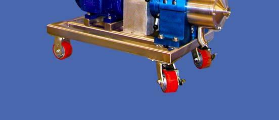
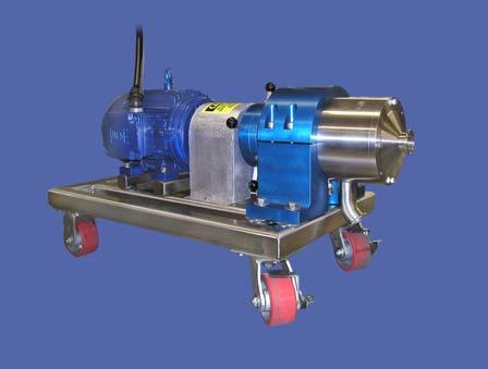


1 Operation and Maintenance Instructions One Research Drive Stratford, CT (203)


2 Installation and Start-up Do not perform following adjustments without disconnecting power Place unit in desired location. Bolting to floor is usually not required but if desired, make sure floor is level. Be careful not to distort mill frame by bolting to an uneven surface. Connect motor leads properly according to the diagram provided with the motor. Only a certified electrician on site should perform this task. Steel and Stainless Steel Stators Only: Connect cooling water to the mill Head inlet port, shown to the left and connect outlet port to drain. Stator must be cooled when unit is used in continuous production or when rotor and stator are operated at close gap settings. Cooling water serves to control thermal expansion and prevent surface distortion of the shaft and stator. Use of cooling water is optional for intermittent use, such as in a laboratory. Connect stator cooling water; ¼ NPT IN OUT Before starting the mill, take serious heed of the notices below: Notice: Do not operate the mill without product or water charged in the head assembly. Running the mill dry will severely damage the seal assembly! Notice: Make sure rotor and stator are not in contact; galling of the stainless steel rotors and stators may occur. To ensure the rotor and stator are not in contact, insert the Adjusting Lever into the Adjusting Ring and rotate clockwise to completely open the Gap Setting, a marker on the head assembly will indicate this direction. Notice: If the unit you have purchased possesses a flush mechanical seal as opposed to an O-ring seal assembly, ensure that flushing water is connected to the fittings supplied on the unit. Flushing water must be connected prior to operation or seal assembly will be damaged. Motor rotation needs to be verified after wiring is completed; an arrow on the mill indicates proper rotation. Once water or process material is loaded in the mill, start the mill and confirm proper rotation. Direction of Shaft and Rotor rotation is always counter-clockwise as you stand facing the unit. Direction is also indicated by an arrow on top of the unit. 2

3 Stop the mill once direction is verified; change any 2 leads on the source power wiring to change rotation. Only a certified electrician should do this. The unit has been tested and calibrated at the factory prior to shipping. The stator is properly centered and the indicator ring indicates the correct rotor/stator gap. However, jolting and bumping during shipping may cause maladjustment and it is wise to check gap setting Zero and Center prior to use. You will need to know these procedures for mill re-assembly as well. These procedures are detailed below in the next section. After adjusting the Zero, Center and Rotation of the mill, flush out the water or material used to charge the mill head when the mill was started initially. Adjust the gap between the Rotor and Stator by rotating the Adjusting Ring. Once a gap setting is established, you can lock the setting in place by tightening the Locking Screws. Rotor Locking Screws Adjusting Ring; turn to vary gap setting Notice: For more detailed information on gap setting adjustments, read the next section. Charge the mill with product either by gravity feed or pressure feed. Notice: If you use a pressure feeding system or a pump feeding system, ensure that a gauge is installed prior to the mill to monitor inlet pressure. The seal assembly will only handle about 50 psi. Start the mill. You can adjust the gap setting as the mill is running. As you close the gap, flow will begin to decrease. Set the mill at a specific gap setting and take a sample of the product. Based on the analysis of your sample, either open or close the gap taking additional samples at various settings to determine the best setting. If during operation of a colloid mill with the single mechanical seal you have a seal failure, material will leak out of the Seal Weep piping. If you have a flush mechanical seal, seal failure would be indicated by loss of pressure in the seal chamber. 3

4 Seal Weep Opening Rotor - Stator Gap Setting Adjustments Turning the Adjusting Ring in either direction rotates the Adjusting Cylinder; this cylinder is housed in a threaded bushing. The Shaft, Bearing Housing and Rotor are connected to this cylinder and move in synchronization with it. Rotating the Adjusting Ring clockwise while standing in front of the mill will increase the gap setting; an arrow on the head assembly indicates the rotational direction used to close the gap setting. The gap setting measurement is indicated by the Indicating Ring which is marked with numbers from 0 to If properly adjusted the number 0 will align with a mark in the top of the hanger when the rotor and stator are just barely touching. Turning the Adjusting Ring to each successive number will open the gap one one-hundredths (.01) of an inch; the max adjustment is 5 complete turns, or 0.25 inch gap setting. The gap can be opened or closed whether the unit is running or not. However, always start the unit with a gap of at least 0.10 and slowly close to the desired setting in order to prevent momentary motor overload. Thermal expansion during the operation will close the gap slightly, stainless steel rotors and stators should not be operated closer than.001 inch. Stainless steel will gall upon contact, usually requiring re-machining of the rotor and stator. Abrasive stones, ni-resist, and certain tool steel combinations may be operated close to contact. Do not start with the rotor and stator in contact, and keep close watch on the unit when operating at a near zero gap setting. The rotor - stator gap setting will alter with time due to normal wear. It should be checked every 3-6 months to ensure proper Zero and Center. Zeroing Disconnect the electrical supply. Zero and Center Procedures Flush the mill head assembly with hot water or cleaning solution to ensure the rotor and stator surfaces are clean. Ensure the Hear Cover bolts are tightly secured. By hand, without placing fingers, hands, etc., near the nip points, carefully turn the drive belts or one of the pulleys/couplings in the proper direction while closing the rotor - stator gap with the Adjusting Ring. 4

5 When the rotor just begins to make contact with the stator you will feel a marked resistance to turning and hear a grinding sound. Back off very slightly and turn the Indicating Ring so that the zero position is aligned with the mark on the hanger. Indicating Ring w/ 5 set screws Zero Indicator mark The unit is now properly zeroed. Centering Disconnect electrical supply. Slightly loosen the Head Cover bolts so the Stator can move. Close the rotor-stator gap using the Adjustment Ring. Without placing fingers, hands, etc., near the nip points, turn the rotor by hand using either the belt or one of the pulleys/couplings. While alternately closing the gap and turning the Rotor, rock the Stator back and forth and up and down. When the stator is too tight to move, tighten Head Cover bolts. The stator should then be properly centered. To check the centering, remove the stator and make 3 or 4 equidistant chalk marks on the largest diameter surface of the rotor. A thin line of grease or machinist's bluing paste may also be used if desired. Reinstall the stator and close the gap while turning the rotor by hand. Stop when the rotor makes contact with the stator. Remove the stator and check the chalk or grease. If the lines are smeared about equally, the stator is centered. If not, repeat the above steps. Removal Component Removal and Replacement Procedures Disconnect all seal and shaft cooling water as well as discharge and inlet piping to and from the mill. Unbolt the Head Cover bolts. For smaller mills there are 3; for larger mills there are 4 or more. 5


6 Remove Head Cover bolts in 4 or more places Remove the Stator using the set screws in the Head Cover to jack the Head Cover/Stator assembly away from the head. Never use a screwdriver or anything else to pry the head cover loose. Damage to the mating surfaces could cause leakage and prevent the stator from being aligned with the rotor. Be careful not to drop the stator assembly. For smaller mills it is not necessary to use jacking screws. Use one of the Head Cover bolts as a jacking screw in the threaded opening on the Head Cover Once the Stator has been removed, the Rotor and Auger will be exposed. Stator; has cooling jacket opening isolated by O- rings Auger holding Rotor in place Remove the Auger using a 5/16 wrench. Take precaution as the Rotor is spring-loaded and will shift outward as you remove the Auger. Watch for the small key that aligns the Rotor with the mill shaft. 6


7 Behind the Rotor is the seal spring and seal-spring retainer that help hold the seal assembly in place during operation. These fit very loosely over the shaft. Behind these are the Seal Assembly consisting of the Seal and Ceramic Seat. Seal Holder Seal Seal spring Using a 3¼ inch socket head, or seal removal tool provided by Sonic, remove the Seal Holder. The Seal will slide off the shaft in the process as the Seal Holder is unscrewed. The Ceramic Seat can be pushed out from the back either by hand or by tapping lightly with a rubber hammer and screw driver. Seal Seal Holder Ceramic Seat Remove Ceramic Seat by pressing out the back of Seal Holder The removal of a double flush mechanical seal is the same and is accomplished by removing the seal holder and removing the seal and ceramic seat therein. Before re-assembling the mill; wipe the end of the Head and the inside of the Head Cover with a clean rag to make sure there is no foreign material to prevent proper seating of the stator. Replacement; Mechanical Seal Assembly Place O-ring lubrication around the ceramic Seal Seat O-ring. Insert the Ceramic Seat into the Seal Holder; when doing so make sure the shiny smooth surface faces out toward you - this will be the mating surfaces for the Seal Assembly to be installed next. The side to face inward will be rough with black markings. Thread the Seal Holder into the back of the Head of the mill and tighten. Nmote that the Seal Holder threads on counter clockwise. 7

8 Place O-ring lubrication around the inside of the Seal Assembly. Lubricate inside of the elastomeric seal Slip the Seal Assembly over the Shaft and push it against the Ceramic Seat; the elastomeric end of the Seal should go on first facing the Seat. Install the Seal Spring and Washer followed by the Rotor. Replacement; Rotor Check to see that the Shaft and the shoulder on the Shaft are free of any foreign material. Check that Rotor bore and the back of the Rotor are clean. Install the Rotor on the Shaft. While pushing the rotor back against the spring, insert the Shaft Key. While still holding the Rotor against the Spring, screw the Auger into the end of the shaft. Push the Rotor as far back as possible while tightening the Auger. Use the wrench to snug up the Auger. Check that the Rotor is tight against the shaft shoulder by pushing on it and turning the Auger with the wrench. If the Rotor is not tight, the rotor-stator gap cannot be properly set. Replacement; Stator Lubricate the O-rings, then insert the Stator and tighten the Head Cover bolts alternately from side to side. Make sure the jack screws have been retracted and there is nothing caught between cover and head which would prevent proper seating. Be careful not to damage the O-rings. Check Zero and Centering following the procedures detailed previously in this manual. Bearing Removal and Replacement 8

9 Refer to Drawing TH4MB-A-05-A.dwg on website Tech Support Removal Make sure power to unit is off and disconnected. Remove guard and drive belts and pulley, or coupling. Remove the Stator, Auger, Rotor and Seal Holder as described earlier. Remove Advancer Bolts, Item 23, and the Advancer Pull Dowel, Item 24. Remove the socket head Set Screw, Item 30, then the Pull Dowel, Item 20. Thread the Advancer, Item 3, off the end of the mill. Using the exposed end of the Shaft, Item 4, at the back end of the mill, pull the Shaft and connected Bearing Sleeve out of the mill. From the Bearing Sleeve remove the Shaft Lock Washer, Item 17. Place Bearing Sleeve in an arbor press with the drive end of Shaft facing upward; this would be the end of the Shaft that previously held the motor coupling. 9
10 Make sure Bearing Sleeve is properly supported and clamped in place on the press. Press the Shaft through the Bearing Sleeve; the first bearing and the Bearing Spacer, Item 5, will be removed with the Shaft. Flip the Bearing Sleeve and remove the other bearing from the opposite end using the arbor press. Replacement Make sure all components are clean of debris. Lubricate the Shaft and the inner wall of the Bearings. Place the front bearing in proper orientation on the arbor press. Make sure the inner face of the Bearings are properly supported, otherwise, during press the Bearing will get damaged. Press the bearing into the Bearing Sleeve, then flip the Bearing Sleeve. Insert the Bearing Spacer, Item 5, and the next bearing and the Shaft and press into place; Shaft should be pressed in with the keyed end facing out toward the press. Thread on and tighten the Shaft Lock Washer. Lubricate the O-rings on the Bearing Sleeve and insert the Bearing Sleeve into the mill. Thread the Advancer into place and tighten with the proper bolts and dowels. Insert upper Pull Dowel, Item 20, and set screw, Item 30. Cleaning The unit should be cleaned between batches or at least once a week if used in continuous service. Remove the stator assembly and wash out the stator, rotor, and head, using hot water or an appropriate solvent. Unless the stator is removed, tramp metal, stones, and other large debris caught in the stator will not be removed. If cleaning is attempted by opening the rotor-stator gap without removing the stator, this debris may pass between the rotor and stator and damage or score the surfaces. Never flush abrasive stones with cold water after use. They become hot in use and will crack if exposed to cold water immediately. Use only very hot water to flush. Lubrication The adjustment cylinder has been appropriately greased at the factory. Additional grease is not necessary. Excessive lubrication may be damaging to the bearings and may cause premature failure. When new bearings are installed, they should be greased according to the bearing manufacturer s specifications. The grease used at the factory is Lubriko M-6. 10
Maintenance Information
 16573370 Edition 2 February 2014 Air Grinder 99V Series Maintenance Information Save These Instructions Product Safety Information WARNING Failure to observe the following warnings, and to avoid these
Fluid-O-Tech ROTOFLOW ROTARY VANE PUMP REBUILD MANUAL
 Fluid-O-Tech PUMP TECHNOLOGY AT ITS BEST WWW.FLUID-O-TECH.COM Office: 161 Atwater St., Plantsville, CT 06479 Phone: (860) 276-9270 Fax: (860) 620-0193 ROTOFLOW ROTARY VANE PUMP REBUILD MANUAL 08/09 Ed.,
Maintenance Information
 16573321 Edition 3 February 2014 Air Grinder Series 61H Maintenance Information Save These Instructions Product Safety Information WARNING Failure to observe the following warnings, and to avoid these
Maintenance Information
 80234313 Edition 2 May 2014 Air Grinder, Die Grinder, Sander and Belt Sander Series G1 (Angle) Maintenance Information Save These Instructions Product Safety Information WARNING Failure to observe the
Sachs shock manual. ( ) 2 & 4 Stroke RR Enduro. ( ) RS Dual Sport
 2 & 4 Stroke RR Enduro. ( ) RS Dual Sport") Sachs shock manual (2013 2015) 2 & 4 Stroke RR Enduro (2014-2015) RS Dual Sport 1 Introduction The procedures in this manual must take place in a clean environment using professional tools and some specific,
Sachs shock manual (2013 2015) 2 & 4 Stroke RR Enduro (2014-2015) RS Dual Sport 1 Introduction The procedures in this manual must take place in a clean environment using professional tools and some specific,
A/C COMPRESSOR SERVICING Article Text 1991 Saab 9000 For Copyright 1997 Mitchell International Friday, October 15, :22PM
 Article Text ARTICLE BEGINNING 1991 GENERAL SERVICING Compressor Service * PLEASE READ THIS FIRST * CAUTION: When discharging air conditioning system, use only approved refrigerant recovery/recycling equipment.
Maintenance Information
 Form 16573321 Edition 1 July 2004 Air Grinder Series 61H Maintenance Information Save These Instructions Always wear eye protection when operating or performing maintenance on this tool. Always turn off
Maintenance Information
 16573347 Edition 2 February 2014 Air Grinder Series 88H Maintenance Information Save These Instructions Product Safety Information WARNING Failure to observe the following warnings, and to avoid these
Maintenance Information
 04581245 Edition 2 May 2014 Air Grinder, Die Grinder and Sander Series G2 (Angle) Maintenance Information Save These Instructions Product Safety Information WARNING Failure to observe the following warnings,
Maintenance Information
 80234313 Edition 1 June 2006 Air Grinder, Die Grinder, Sander and Belt Sander Series G1 (Angle) Maintenance Information Save These Instructions WARNING Always wear eye protection when operating or performing
Introduction. Pressed Shaft Flowmeter. Flowmeter Service Kits. Disassembly. Idler Shaft Removal
 Flowmeter Service Kits Introduction See Figure. This instruction sheet provides repair procedures for flowmeters that use either pressed or screw-in shafts. Refer to the applicable repair procedure: Pressed
3M Overhaul Service Kit
 SERVICE INSTRUCTIONS FOR 3M 12,000 RPM 3 in. (77 mm) RANDOM ORBITAL SANDERS 3M Overhaul Service Kit The part number 20346, 3M Overhaul Service Kit, contains all the replacement parts that naturally wear
Installation Instructions
 Preparing your vehicle to install your brake system upgrade 1. Rack the vehicle. 2. If you don t have a rack, then you must take extra safety precautions. 3. Choose a firmly packed and level ground to
METERING VALVE 2" STEM GUIDED
 2" STEM GUIDED All Rights Reserved. All contents of this publication including illustrations are believed to be reliable. And while efforts have been made to ensure their accuracy, they are not to be construed
Maintenance Information
 45528270 Edition 1 June 2007 Barring Motor T480 Series Maintenance Information Save These Instructions WARNING Always wear eye protection when operating or performing maintenance on this Barring Motor.
Maintenance Information
 16572679 Edition 2 May 2014 Air Drill QP Series Maintenance Information Save These Instructions Product Safety Information WARNING Failure to observe the following warnings, and to avoid these potentially
Fisher 657 Diaphragm Actuator Sizes and 87
 Instruction Manual 657 Actuator (30-70 and 87) Fisher 657 Diaphragm Actuator Sizes 30 70 and 87 Contents Introduction... 1 Scope of Manual... 1 Description... 2 Specifications... 2 Installation... 3 Mounting
1. Remove the crankshaft pulley, engine coolant pump pulley and drive belt. 2. Remove the timing belt cover.
 DISASSEMBLY 1. Remove the crankshaft pulley, engine coolant pump pulley and drive belt. 2. Remove the timing belt cover. 3. Turn the crankshaft clockwise and align the timing marks so as to bring the No.
INSTRUCTION MANUAL IM-422 For HTC/COUPLING ASSEMBLY HC-8088
 No Revision 2/22/18 INSTRUCTION MANUAL IM-422 HTC/COUPLING ASSEMBLY The Riverhawk Company reserves the right to make changes updating this document without dissemination or notice. The latest revision
REPAIR INSTRUCTION - MP4120-SWS/MP4124-SWS
 Disassembly sequence REPAIR INSTRUCTION - MP4120-SWS/MP4124-SWS 1. With a 27mm wrench, remove the three discharge plugs (#48) and three inlet plugs (#42A) from the manifold (#43). 2. Inspect the plug o-rings
Difficulty Grading expert Wrench Time 1 hour Tip, Strip or Tune Strip Spares Needed Oil Seals 4.99 (pr), Dust Seals 5.75 (pr)
, Dust Seals 5.75 (pr)") URFNVKR[VHUYLFH Difficulty Grading expert Wrench Time 1 hour Tip, Strip or Tune Strip Spares Needed Oil Seals 4.99 (pr), Dust Seals 5.75 (pr) 22mm socket Rubber mallet Allen keys Small Phillips screwdriver
URFNVKR[VHUYLFH Difficulty Grading expert Wrench Time 1 hour Tip, Strip or Tune Strip Spares Needed Oil Seals 4.99 (pr), Dust Seals 5.75 (pr) 22mm socket Rubber mallet Allen keys Small Phillips screwdriver
SCAMP AND UTILITY MODELS SELF-PROPELLED BELT DRIVE SERVICING 4502, 4503, 8602, 8603 WITH F SERIES ENGINES
 4502, 4503, 8602, 8603 WITH F SERIES ENGINES Adjustments and servicing of the Scamp and Utility self-propelled mowers are very different from all previous models of self-propelled mowers. BEFORE ANY ADJUSTMENTS
HYDRAULICS. TX420 & & lower. Hydraulic Tandem Pump Removal. 4. Remove the LH side panel (Fig. 0388).
.") TX420 & 425 240000299 & lower 4. Remove the LH side panel (Fig. 0388). Hydraulic Tandem Pump Removal Note: Cleanliness is a key factor in a successful repair of any hydraulic system. Thoroughly clean all
TX420 & 425 240000299 & lower 4. Remove the LH side panel (Fig. 0388). Hydraulic Tandem Pump Removal Note: Cleanliness is a key factor in a successful repair of any hydraulic system. Thoroughly clean all
POWER STEERING PUMP REBUILDING SPK101 Read instructions completely before removal & disassembly
 POWER STEERING PUMP REBUILDING SPK101 Read instructions completely before removal & disassembly DISASSEMBLY: 1. Remove pump from car and allow to drain. 2. Remove pulley from front of pump. This requires
Timing Belt: Service and Repair
 2000 Hyundai Sonata L4-2.4L Page 1 Timing Belt: Service and Repair REMOVAL 1. Remove the crankshaft pulley, engine coolant pump pulley and drive belt. 2. Remove the timing belt cover. 2000 Hyundai Sonata
Maintenance Information
 16575128 Edition 2 May 2014 Air Grinder, Sander or Polisher 77A Series Maintenance Information Save These Instructions Product Safety Information Failure to observe the following warnings, and to avoid
D/G-35 Maintenance. Shutdown Procedure During Freezing Temperatures. Daily. Periodically
 D/G-35 Maintenance NOTE: The numbers in parentheses are the Reference Numbers on the exploded view illustrations found later in this manual. Daily Check the oil level and the condition of the oil. The
300 SERIES 331, 332, 333, 344, 356 AND 367 MODELS
 Section: MOYNO 500 PUMPS Page: 1 of 8 Date: March 1, 1998 SERVICE MANUAL MOYNO 500 PUMPS 300 SERIES 331, 332, 333, 344, 356 AND 367 MODELS Mechanical Seal Models Packing Gland Models MODELS DESIGN FEATURES
CONTENTS. VIKING PUMP, INC. A Unit of IDEX Corporation Cedar Falls, IA USA SECTION TSM 710.1
 TECHNICAL SERVICE MANUAL industrial heavy duty motor speed pumps SERIES 4076 AND 4176 SIZES hle, ate and ale SECTION TSM 710.1 PAGE 1 of 8 ISSUE B CONTENTS Introduction....................... 1 Safety
3.2 DRIVE TORQUE HUB. Roll, Leak and Brake Testing SECTION 3 - CHASSIS & TURNTABLE. 3-2 JLG Lift
 3.2 DRIVE TORQUE HUB Roll, Leak and Brake Testing 10 LUG PATTERN Torque-Hub units should always be roll and leak tested before disassembly and after assembly to make sure that the unit's gears, bearings
B&M / INTRODUCTION
 INSTALLATION INSTRUCTIONS FOR B&M AUTOMATIC TRANSMISSIONS REPLACING GM TH350, TH400, and TH700R4 / 4L60 (not including 4L60E / electronic shift models) B&M part numbers: 102002-103005 - 107101-107104 107105-107106
Maintenance Information
 16575243 Edition 2 October 2013 Air Screwdrivers 1R Series Maintenance Information Save These Instructions Product Safety Information WARNING Failure to observe the following warnings, and to avoid these
CALIFORNIA TRIMMER MOWER MAINTENANCE MANUAL
 CALIFORNIA TRIMMER MOWER MAINTENANCE MANUAL 2 Table of Contents Section 1: General Information Page Handle Assembly Instructions 4 Maintenance All Models 6 Oil Change Procedures All Models 9 Height Adjustment
TECHNICAL BULLETIN. TP Issued Servicing Rockwell s TB Series Trailer Axles with Unitized Hub Assemblies
 TECHNICAL BULLETIN TP-96175 Issued 12-96 Servicing Rockwell s TB Series Trailer Axles with Unitized Hub Assemblies TB Series Trailer Axles Introduction Rockwell s TB series trailer axle features a permanently
TECHNICAL SERVICE MANUAL
 Electronic copies of the most current TSM issue can be found on the Viking Pump website at www.vikingcom TECHNICAL SERVICE MANUAL abrasive liquid pumps SERIES 4625 SIZES f - fh SECTION TSM 410.1 PAGE 1
PRODUCT OBSOLETED 4Q16
 Electronic copies of the most current TSM issue can be found on the Viking Pump website at www.vikingcom TECHNICAL SERVICE MANUAL abrasive liquid pumps SERIES 4625 SIZES f - fh SECTION TSM 410.1 PAGE 1
SECTION G2: CABLE PROCESSOR MODULE MAINTENANCE
 SECTION G2: CABLE PROCESSOR MODULE MAINTENANCE Cable Processor Module overview WARNING! When tipping the Cable Processor Module back, (after removing the toggle arm pin), use extreme caution not to drop
Maintenance Information
 Form 04584058 Edition 1 November 2004 Air Impactool 2141P and 2141PSP Maintenance Information Save These Instructions Disassembly General Instructions 1. Do not disassemble the tool any further than necessary
PRODUCT USE INFORMATION
 9RC61000 Jeep YJ Body Lift Thank you for choosing Rough Country for all your suspension needs. This body lift fits both manual and Automatic equipped vehicles!!! Refer to last page of this Instruction
Rineer 15 Series Hydraulic Motor Service Manual
 Section 4-2 Rineer 15 Series Hydraulic Motor Service Manual Removal of 15 Series Shaft Seal Step 1 Remove snap ring. See Figure 1. WARNING: Use caution when removing snap ring. If released accidentally,
ENGINE TUNE-UP INSPECTION OF ENGINE COOLANT INSPECTION OF ENGINE OIL INSPECTION OF BATTERY. INSPECTION OF AIR FILTER (Paper Filter Type)
") ENGINE MECHANICAL - Engine Tune-Up EM-17 ENGINE TUNE-UP INSPECTION OF ENGINE COOLANT (See steps 1 and 2 on page CO-4) INSPECTION OF ENGINE OIL (See steps 1 and 2 on page LU-5) INSPECTION OF BATTERY (See
ENGINE MECHANICAL - Engine Tune-Up EM-17 ENGINE TUNE-UP INSPECTION OF ENGINE COOLANT (See steps 1 and 2 on page CO-4) INSPECTION OF ENGINE OIL (See steps 1 and 2 on page LU-5) INSPECTION OF BATTERY (See
PILLOWS DECK-MOUNT BATH FAUCET WITH FLUME SPOUT
 PILLOWS DECK-MOUNT BATH FAUCET WITH FLUME SPOUT BEFORE YOU BEGIN NOTES Observe all local plumbing and building codes. Advance planning before installation is crucial. Carefully read the entire instructions
KENNEDY VALVE RESILIENT WEDGE GATE VALVE MAINTENANCE MANUAL
 KENNEDY VALVE Division of McWane, Inc. 1021 East Water Street P.O. Box 931 Elmira, New York 14902-0931 Telephone (607) 734-2211 Fax (607) 734-1003 KENNEDY VALVE RESILIENT WEDGE GATE VALVE MAINTENANCE MANUAL
Valtek Auxiliary Handwheels and Limit Stops
 Valtek Auxiliary s and Limit Stops Table of Contents Page 1 General information 2 Installation 2 Side-mounted handwheels, size 25 and 50 (linear actuators) 3 Side-mounted handwheels, size 100 and 200 (linear
ZTM AND ZTMB ZENNER TURBINE METERS INSTALLATION, MAINTENANCE AND SERVICING
 ZTM AND ZTMB ZENNER TURBINE METERS INSTALLATION, MAINTENANCE AND SERVICING INSTALLATION 1. The meter is intended for measuring potable, cold water in one direction. 2. The meter is to be installed in a
Crestline Altra Series TM Dampener. Installation Instructions. Heidelberg GTO. X /98 Rev-A
 Crestline Altra Series TM Dampener Installation Instructions Heidelberg GTO X88-63 7/98 Rev-A GENERAL INFORMATION ATTENTION CRESTLINE ALTRA SERIES TM DAMPENER OWNER! Accel Graphic Systems provides parts
I-317. AWWA Check Valves WARNING INSTALLATION AND MAINTENANCE INSTRUCTIONS SERIES 317 WARNING
 Read and understand all instructions before attempting to install, remove, adjust, or perform maintenance on any Victaulic piping products Wear safety glasses, hardhat, and foot protection. Failure to
Honda Civic Oil Change
 1988-1991 Honda Civic Oil Change Change the oil in your '88-'91 Honda Civic to improve engine performance and longevity. Written By: Phillip Takahashi ifixit CC BY-NC-SA www.ifixit.com Page 1 of 13 INTRODUCTION
Service and Maintenance. Repositioning of the Motor Conduit Box and Cable Entry Motor Frame Sizes
 Service and Maintenance Repositioning of the Motor Conduit Box and Cable Entry Motor Frame Sizes 71-132 Overview 1 2 3 4 Safety Tooling Changing the Conduit Box Position Changing the Cable Entry Safety
Installation Manual For ISL98, ISL03, ISL07, ISC07
 Installation Manual For ISL98, ISL03, ISL07, ISC07 Table of Contents Section 1: Introduction... 3 Housing Identification... 3 Engine Identification... 3 Special Tools... 3 Automatic Transmissions... 3
Written By: David Hodson
 2008-Present Scion xb Oil Change Second generation Scion xb oil change. Written By: David Hodson ifixit CC BY-NC-SA www.ifixit.com Page 1 of 19 INTRODUCTION Change the oil in your 2008 or newer Scion xb
3M Overhaul Service Kit
 SERVICE INSTRUCTIONS FOR 3M 12,000 RPM 5 in. (127 mm) and 6 in. (150 mm) RANDOM ORBITAL SANDERS 3M Overhaul Service Kit The part number 20347, 3M Overhaul Service Kit, contains all the replacement parts
FOX Racing Shox Bypass Technical Manual.
 FOX Racing Shox Bypass Technical Manual. The following technical manual will be using a 2.5 dia. shock with three tubes for descriptions and illustrations. Your shock may differ in the number of tubes,
GM C10 Street Grip
 Part # 11365010/11365110-1973-1987 GM C10 StreetGrip Front Components 11369590 Delrin Control Arm Bushings 11369300 Drop Spindles 11362350/11362351 Front CoilSpring Kit 11369515 Front HQ Series Shocks
Vickers. Overhaul Manual. Vane Pumps. Small and Large Series Combination Pumps VC(K)(S)-**-(*)*D*-6(1) VC(K)(S)-**-(*)-*-*D*-5(1)
(S)-**-(*)*D*-6(1) VC(K)(S)-**-(*)-*-*D*-5(1)") Overhaul Manual Vickers Vane Pumps Small and Large Series Combination Pumps VC(K)(S)-**-(*)*D*-6(1) VC(K)(S)-**-(*)-*-*D*-5(1) Revised 12/1/86 I-3150-S Table of Contents Section I. Introduction................................................................................
Overhaul Manual Vickers Vane Pumps Small and Large Series Combination Pumps VC(K)(S)-**-(*)*D*-6(1) VC(K)(S)-**-(*)-*-*D*-5(1) Revised 12/1/86 I-3150-S Table of Contents Section I. Introduction................................................................................
Mitsubishi Lancer Oil Change (2.0L I4 DOHC)
") 2002-2007 Mitsubishi Lancer Oil Change (2.0L I4 DOHC) Change the oil in your '02-'07 Mitsubishi Lancer, with 2.0L I4 DOHC engine, to improve engine performance and longevity. Written By: Phillip Takahashi
2002-2007 Mitsubishi Lancer Oil Change (2.0L I4 DOHC) Change the oil in your '02-'07 Mitsubishi Lancer, with 2.0L I4 DOHC engine, to improve engine performance and longevity. Written By: Phillip Takahashi
DrVanos.com Stage II Installation Instructions. Tool rental is available with the purchase of a vanos kit *See website for more info*
 DrVanos.com Stage II Installation Instructions Special Tools Needed: Camshaft locking tool TDC Crank pin Sprocket turning tool Tool rental is available with the purchase of a vanos kit *See website for
ALL AMERICAN BILLET. Front Drive System - Small Block Ford Installation Instructions
 ALL AMERICAN BILLET Front Drive System - Small Block Ford Installation Instructions Small Block Ford with AC & PS All American Billet Store (800) 764-0926 www.allamericanbilletstore.com Items needed for
SERVICE MANUAL 200 SERIES MOTORIZED 20352, 20452, 20551, 20552, AND MODELS
 Section: MOYNO 500 PUMPS Page:1 of 4 Date: March 1, 1998 SERVICE MANUAL MOYNO 500 PUMPS 200 SERIES MOTORIZED 20352, 20452, 20551, 20552, 22051 AND 22052 MODELS DESIGN FEATURES Housing: AISI 316 stainless
FORK FREE PISTON MODIFICATION 2011 HONDA CRF250R
 217 Lorain Place Los Gatos, California 95032 408.406.2089 www.smartperformanceinc.com www.spi-racing.com FORK FREE PISTON MODIFICATION 2011 HONDA CRF250R WHAT? All production versions of the 2011 HONDA
Installation Manual TWM Performance Short Shifter Cobalt SS/SC, SS/TC, HHR SS, Ion Redline and Saab 9-3
 Page 1 Installation Manual TWM Performance Short Shifter Cobalt SS/SC, SS/TC, HHR SS, Ion Redline and Saab 9-3 Please Note: It is preferable to park on a flat surface, as you will have to engage and disengage
Service Manual Air Tech Second Stage
 Service Manual Air Tech Second Stage Copyright 2002, Cressi-sub Revised 3/2002 2 Air Tech Second Stage Service Manual Contents BEFORE STARTING... 3 DISASSEMBLY... 3 PARTS CLEANING AND LUBRICATION... 9
SERVICE MANUAL L130B / L4130 Series Logstacker Drive Axle With Bolt-On Stub End Retainer
 SERVICE MANUAL L130B / L4130 Series Logstacker Drive Axle With Bolt-On Stub End Retainer Page 1 Allied Form #80-930 Rev 07/2009 SERVICE MANUAL LOG STACKER DA202 DRIVE AXLE TABLE OF CONTENTS PROCEDURE FOR
INSTALLATION INSTRUCTIONS
 INSTALLATION INSTRUCTIONS PERFORMANCE AT THE WHEELS KITS W156-6 & W156-7 1965-74 MOPAR B & E BODY Thank you for choosing STAINLESS STEEL BRAKES CORPORATION for your braking needs. Pleases take the time
Air / Hydraulic Under Axle Jack
 655 Eisenhower Drive Owatonna, MN 55060-0995 USA Phone: (507) 455-7000 Tech. Serv.: (800) 533-6127 Fax: (800) 955-8329 Order Entry: (800) 533-6127 Fax: (800) 283-8665 International Sales: (507) 455-7223
ONYX VALVE CO MODEL CAR, CAP-PFO Installation & Maintenance
 ONYX VALVE CO MODEL CAR, CAP-PFO Installation & Maintenance OPERATION: (4-2010) The Onyx series CAR-PFO and CAP-PFO pinch valves fail open on loss of air. The simple spring and air bag arrangement drives
Southwest Windpower Instruction Sheet AIR-X Circuit Replacement Kit
 Southwest Windpower Instruction Sheet AIR-X Circuit Replacement Kit Tools Required 5 / 32 Hex key 5 / 16 Hex key 7 / 64 Hex key Standard screwdriver Pair of external snap ring pliers Rubber mallet Hammer
TECHNICAL SERVICE MANUAL
 Electronic copies of the most current TSM issue can be found on the Viking Pump website at www.vikingpump.com TECHNICAL SERVICE MANUAL industrial heavy duty motor speed pumps SERIES 4076 AND 4176 SIZES
Wheel Horse. 44 Snowthrower. for 5xi Lawn and Garden Tractors. Model No & Up. Operator s Manual
 FORM NO. 8 Rev A Wheel Horse Snowthrower for 5xi Lawn and Garden Tractors Model No. 7966 890050 & Up Operator s Manual IMPORTANT: Read this manual, and your tractor manual, carefully. They contain information
INSTALLATION GUIDE TCP RCKM-01
 READ ALL INSTRUCTIONS COMPLETELY AND THOROUGHLY UNDERSTAND THEM BEFORE DOING ANYTHING. CALL TOTAL CONTROL PRODUCTS TECH SUPPORT (916) 388-0288 IF YOU NEED ASSISTANCE. INSTALLATION GUIDE TCP RCKM-01 Manual
ONYX VALVE CO MODEL DAO-ADA Installation & Maintenance
 ONYX VALVE CO MODEL DAO-ADA Installation & Maintenance OPERATION: (4-2010) The Onyx DAO-ADA pinch valve is an open frame valve without housing enclosure and fails last position on loss of air. This actuator
RUGBY HOIST CYLINDERS SERVICE BULLETIN
 TRUCK BODIES & EQUIPMENT INTERNATIONAL, Inc. Website: www.rugbymfg.com E-mail: sales@rugbymfg.com Phone: (701) 776-5722 Toll Free: (800) 869-9162 RUGBY HOIST CYLINDERS SERVICE BULLETIN This bulletin applies
Note: Replace the washer and the spacer above the turgo or the shaft adapter with the spacer above the washer as shown in the following pictures.
 BEARINGS, SERVICE & ASSEMBLY IMPORTANT Bearing maintenance is important. You should replace bearings ONCE PER YEAR or as soon as you notice any looseness from wear. If they are too loose, severe damage
ONYX VALVE CO MODEL DAC-PFO Installation & Maintenance
 ONYX VALVE CO MODEL DAC-PFO Installation & Maintenance OPERATION: (01-10) The Onyx series DAC-PFO pinch valve fails open on loss of air. This simple spring and air bag arrangement that drives a pair of
REMOVAL & INSTALLATION
 REMOVAL & INSTALLATION NOTE: For reassembly reference, label all electrical connectors, vacuum hoses and fuel lines before removal. Also place mating marks on engine hood and other major assemblies before
JEEP TJ & (XJ 84-01) ATLAS 2 SP.
 ATLAS 2 SP.") KIT CONSISTS OF: No. Qty Part No. Description 4320 Aerotech Center Way, Page 1 of 9 1 1 302051-RLE BASE- TWIN STICK MOUNT 42RLE 2 1 302080 STUD BOLT 1/2"-13 X 7 (XJ) 3 1 303120 SERRATED LOCK NUT 1/2" X
KIT CONSISTS OF: No. Qty Part No. Description 4320 Aerotech Center Way, Page 1 of 9 1 1 302051-RLE BASE- TWIN STICK MOUNT 42RLE 2 1 302080 STUD BOLT 1/2"-13 X 7 (XJ) 3 1 303120 SERRATED LOCK NUT 1/2" X
INSTALLATION INSTRUCTIONS FOR DSP9600/9100 WHEEL BALANCER
 Form 5063T, 06-05 Supersedes Form 5063T, 02-04 INSTALLATION INSTRUCTIONS FOR DSP9600/9100 WHEEL BALANCER This document provides the information needed to install the DSP9600/9100 Wheel Balancer. NOTE:
COYOTE ENTERPRISES, INC. 9/10 BLAST WHEEL MAINTENANCE & ASSEMBLY MANUAL
 COYOTE ENTERPRISES, INC. 9/10 BLAST WHEEL MAINTENANCE & ASSEMBLY MANUAL Parts & Machinery for the Abrasive Blast Industry 27301 East 121st Street Coweta, Oklahoma 74429 (918) 486-8411 Fax (918) 486-8412
Installation Instructions
 Installation Instructions Rear Disc Brake Conversion Kit Item # RC4001, RC4001X Applications: Mopar 7.25, 8.25, 9.25 Axles Thank you for choosing Leed Brakes for your automotive product needs. Before you
Front Drive System - Big Block Chevy Installation Instructions Big Block Chevy with AC & with PS
 Front Drive System - Big Block Chevy Installation Instructions Big Block Chevy with AC & with PS All American Billet Store (800) 764-0926 www.allamericanbilletstore.com Items needed for install Jack Jack
Assembly & Installation Instructions
 TM P R O D U C T S Assembly & Installation Instructions FOR 28 SERIES SNOWPLOW PIVOT ASSEMBLY AND FLOAT LIMITER 99103000 FOR SERIAL NUMBERS 28D100000 TO 28D100770 97100552A 1. THINK SAFETY, ALWAYS WEAR
1993 Bronco/Econoline/F-Series
 Page 1 of 7 Section 11-02A: Steering Pump, Power, C-II DISASSEMBLY AND ASSEMBLY Workshop Manual Power Steering Pump NOTE: Prior to disassembly of the power steering pump, the pump must be removed from
WARNING Carefully Read These Instructions Before Use
 DO NOT RETURN THIS SPRAYER TO STORE Call: 1-800-950-4458 Backpack Sprayer Use and Care Manual Manufactured for Northern Tool + Equipment Co., Inc. WARNING Carefully Read These Instructions Before Use Model
servicing the swivel
 servicing the swivel The swivel seals and bearings require periodic replacement. This document describes how to determine which service procedure to use to service the swivel assembly, part number 101110.
Maintenance Information
 16575219 Edition 4 October 2013 Air Screwdrivers QP1P, QP1S and QP1T Series Maintenance Information Save These Instructions Product Safety Information WARNING Failure to observe the following warnings,
Maintenance Information
 16605958 Edition 2 May 2014 Air Percussive Rivet Buster Models 9001 and 11001 Maintenance Information Save These Instructions Product Safety Information WARNING Failure to observe the following warnings,
15 Series. Standard Motor. Two Speed Motor
 Repair Man ual 15 Series Standard Motor Two Speed Motor WARNING: RINEER RECOMMENDS FOLLOWING ALL STANDARD SHOP SAFETY PRACTICES SPECIFICALLY INCLUDING WEARING OF EYE PROTECTION. REMOVAL OF SHAFT SEAL
PRIME 4 Service. Smith Meter Rotary Vane Meters. Contents
 Smith Meter Rotary Vane Meters PRIME 4 Service Issue/Rev. 0.4 (7/11) Bulletin MN01041 Contents Trouble Shooting... Page 2 Genuine Smith Meter Parts... Page 2 Special Tools and Fixtures... Page 2 Disassembly
Rear End Installation and Bearing Kit - 8.8in (86-12 V8; V6)
") Rear End Installation and Bearing Kit - 8.8in (86-12 V8; 11-13 V6) Tools Required: Jack Stands 5 Floor Jack 2 Oil Pans 1 Wheel Blocks 2 Differential Oil 3 qts Friction Modifier 3 bottles Tube of Black
Rear End Installation and Bearing Kit - 8.8in (86-12 V8; 11-13 V6) Tools Required: Jack Stands 5 Floor Jack 2 Oil Pans 1 Wheel Blocks 2 Differential Oil 3 qts Friction Modifier 3 bottles Tube of Black
Steam/Water Washdown Units Safety and Operation Installation and Maintenance Instructions
 INSTALLATION AND MAINTENANCE INSTRUCTIONS IM-8-002-US October 2016 Steam/Water Washdown Units Safety and Operation Installation and Maintenance Instructions These instructions should be read by the Company
Raptor "Race 1.5" Upper Control Arm Kit! Installation Guide! Rev 1B! Sales: ext 1! Tech Support: ext 2! Vista Grande!
 Raptor "Race 1.5" Upper Control Arm Kit Installation Guide Rev 1B Sales: 866-691-7750 ext 1 Tech Support: 866-691-7750 ext 2 23231 Vista Grande Laguna Hills, CA 92653 Install Videos: YouTube "Raptor Performance
SERIES PC INSTRUCTION AND OPERATION MANUAL
 MEGGA SERIES PC INSTRUCTION AND OPERATION MANUAL Models PCT and PCF Close-coupled and frame-mounted single-stage horizontal end-suction pumps. WARNING: Read this manual before installing or operating this
Valvetrain, servicing
 Page 1 of 51 15-32 Valvetrain, servicing Note: Cylinder heads with small cracks between the valve seats that are less than 0.3 mm (0.012 in.) wide and/or between one valve seat and only the first 4 threads
TECHNICAL SERVICE MANUAL
 Electronic copies of the most current TSM issue can be found on the Viking Pump website at www.vikingpump.com TECHNICAL SERVICE MANUAL HEAVY-DUTY Stainless steel BRACKET MOUNTED PUMPS SERIES 127 AND 4127
FOR FUTURE REFERENCE SERIES 93HPS
 Hypro Series 93HPS Hydraulically Driven Wetseal Multistage Pumps Repair Manual KEEP FOR FUTURE REFERENCE Form L-1578R Rev. A SERIES 93HPS Hydraulically Driven Stainless Steel Multistage Centrifugal Pumps
ADVANCE ADAPTERS INC. P/N: JEEP TJ & (XJ 84-01) ATLAS 4 SPEED CABLE SHIFTER units built after 5/1/12
 ATLAS 4 SPEED CABLE SHIFTER units built after 5/1/12") Paso Robles, CA 93447 PAGE 1 OF 9 Telephone: (800) 350-2223 Fax: (805) 238-4201 Page Rev. Date: 05-12-15 KIT CONSISTS OF: No. Qty Part No. Description 1 1 302051 BASE- TWIN STICK MOUNT 2 1 302080 STUD
Paso Robles, CA 93447 PAGE 1 OF 9 Telephone: (800) 350-2223 Fax: (805) 238-4201 Page Rev. Date: 05-12-15 KIT CONSISTS OF: No. Qty Part No. Description 1 1 302051 BASE- TWIN STICK MOUNT 2 1 302080 STUD
DESCRIPTION Acura TSX SUSPENSION Front - TSX. NOTE: For system description and component location, see Fig. 1.
 2004 SUSPENSION Front - TSX DESCRIPTION NOTE: For system description and component location, see Fig. 1. Fig. 1: Identifying Front Suspension Components Wednesday, March 12, 2008 8:30:45 8:30:55 PM Page
ONYX VALVE CO MODEL DAO-PFO Installation & Maintenance
 ONYX VALVE CO MODEL DAO-PFO Installation & Maintenance OPERATION: (4-2010) The Onyx DAO-PFO pinch valve is an open frame valve without housing enclosure and fails open on loss of air. The actuator drives
INSTRUCTION AND MAINTENANCE MANUAL: FKL-25, 50, 75, 150, 250 and 400 Style Pump
 FKL Series Pump INSTRUCTION AND MAINTENANCE MANUAL: FKL-5, 50, 75, 150, 50 and 400 Style Pump SANITARY POSITIVE DISPLACEMENT PUMP Fristam Pumps Description This manual contains installation, operation
Gen 2 Raptor Adjustable Spring Perch Collar Installation Guide Rev X1
 Gen 2 Raptor Adjustable Spring Perch Collar Installation Guide Rev X1 Tech Support: 866-691-7750 ext 2 Install Videos: YouTube "Raptor Performance Group" COMPLETELY READ INSTALLATION INSTRUCTIONS PRIOR