Ampco ZP1 Series. Positive Displacement Pumps Installation and Maintenance Manual
|
|
|
- Vernon Gordon
- 6 years ago
- Views:
Transcription


1 Ampco ZP1 Series Positive Displacement Pumps Installation and Maintenance Manual
2 Table of Contents Introduction... 3 Introduction... 3 Ampco Pump Company Warranty... 3 General Information... 3 Shipping Damage or Loss... 3 Receiving/Safety... 4 Pump Receiving... 4 Safety... 4 Pump Information... 5 Pump Information... 5 Label Information... 6 Installation... 7 Installation... 7 Base Arrangement... 7 Piping and Connections... 8 Check/ Isolation/ Relief Valves... 9 Strainers and Gauges Base Alignment Pump Rotation Final Installation Maintenance Maintenance Pump Lubrication Preventive Maintenance/ Inspection Gear and Bearing Inspection Annual Maintenance Cleaning Pump Disassembly Seal Maintenance Single O-Ring Seal Double O-Ring Seal Single Mechanical Seal Double Mechanical Seal Gear Case Maintenance Disassembly Assembly Pump Assembly Pump Clearances Troubleshooting Reconditioning Program Page 2 July 2011
3 Introduction/Warranty Introduction To ensure the best results and service, please read and fully understand this manual prior to putting this pump into service. For any questions regarding operation, maintenance, or installation, please contact your Distributor or Ampco Pumps. Ampco Pumps contact information is as followed: 2045 W. Mill Road Glendale, WI Phone: (800) or (414) Fax: (414) Warranty Ampco Pumps guarantees all of its manufactured products sold to be free from defects in material and craftsmanship for a period of one (1) year from the date of shipment. The warranty does not apply to products requiring repair or replacement due to what is deemed as normal wear and tear. Conditions arising from normal wear and tear include, but are not limited to, standard rotor wear, pump body wear, seal wear, bearing or gear wear. Accident, misuse, or improper maintenance also does not apply to the Ampco Pumps warranty. Ampco Pumps assumes no liability for consequential, incidental or indirect, damages. And the purchaser, by acceptance of delivery, assumes all liability for the consequences of use or misuse by the purchaser, his employees, or others. Unless approved by Ampco Pumps in advance, Ampco Pumps will assume no field related expenses for service or parts. General Information Each Ampco ZP1 pump is fully assembled, lubricated, and tested at the factory and shipped ready for use. Standard maintenance practices are outlined in this manual, for more information please refer to the Maintenance section starting on page 12. Following these guidelines will provide long lasting, trouble free service when the pump(s) is incorporated in a properly designed system. If deemed necessary to return product under warranty, or for some other reason, contact Ampco Pumps to receive a Returned Material Authorization (RMA) number to allow us to expedite this request as quickly as possible. Shipping Damage or Loss Upon receiving equipment that is damaged or lost in transit, immediately file a claim with the carrier. At time of pick-up, the carrier signed the bill of lading, acknowledging that they have received the product from Ampco in good condition. July 2011 Page 3
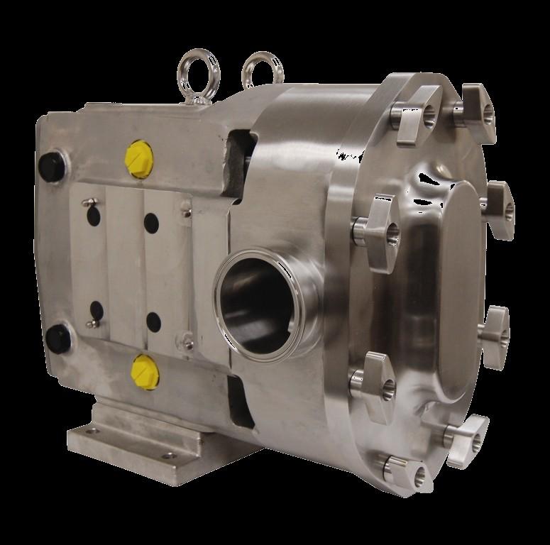
4 Receiving/Safety Pump Receiving Ampco covers all the pumps inlet and discharge ports prior to shipping, to ensure that foreign matter does not enter pump during shipment. If the protective covers are missing upon arrival, remove the pump cover and inspect to ensure it is free from contaminate before turning the shafts. It is important to make note of the pump serial number; this will assist in the process of ordering replacement parts and/or warranty claim. For more information regarding shipment damage or warranty, please refer to the Introduction/Warranty section in this manual. Safety IMPORTANT: Read and understand this manual BEFORE installation, operation or maintenance of the pump. Improper installation, operation or maintenance may result in severe injury or death. Equipment damage caused by user neglect will invalidate the pump warranty. There are safety symbols used throughout this manual identifying safety concerns. WARNING: Hazards or unsafe practices that COULD result in severe personal injury or death, and how to avoid them. CAUTION: Hazards of unsafe practices that COULD result in minor personal injury or damage to product or property. Page 4 July 2011
5 Pump Information Pump Information The design of the ZP pump gear case allows for the shaft location to be universal in order to fit any system requirement. This can be seen in Figures 1 and 2: Figure 1: Shaft Mounts (Upper and Lower) Figure 2: Shaft Mounts (Right and Left) Model Table 1: Standard Operating Parameters Maximum Nominal Capacity GPM M 3 /hr Displacement Gal. / 100 rev Liters / rev Maximum Differential Pressure ZP Temperature Range Standard Optional Maximum Connection Connection Speed Size Size PSI Bar F C in. mm in. mm Rev/min 1.5" 38 1" ZP " ZP " 38 2" ZP to -40 to 1.5" 38 2" ZP " ZP " ZP ZP July 2011 Page 5
 Outlet Maximum Speed PSI Bar F C inches in. mm Rev/ min 1.75 x 6.75 2\" 51 400 ZP1 64 60.0 13.6 15.0 0.")
6 Pump Information Table 2: Rectangular Flange Model Operating Parameters Model Maximum Nominal Capacity GPM M 3 /hr Displacement Gal./ 100 rev Liters / rev ZP Maximum Temperature Differential Range Pressure Rectangular Inlet (W x L) Outlet Maximum Speed PSI Bar F C inches in. mm Rev/ min 1.75 x " ZP to -40 to 2.24 x ½" ZP x " ZP x " For operating parameters that fall outside the standard values defined in Table 1 and Table 2, please contact the Engineering department at Ampco Pumps. The contact phone number is Standard rotors operate within a temperature range of 40 o F to 200 o F. Hot clearance rotors operate at 180 o F to 300 o F. Consult Ampco Pumps for questions on application factors such as temperature, operation speed and differential pressure. Label Information WARNING: Labels are installed on the pump at the factory to ensure proper warning to users. It is important not to remove these labels; doing so may result in injury. The pump is installed with simple, but effective labels to help the customer better understand the ZP1 pump. An identification plate is applied at the factory to help track the life of the pump. The customer should be aware of the pump s serial number and model number prior to contacting Ampco Pumps with any concerns. These labels can be seen below in Figure 3: Figure 3: Important Label Information Page 6 July 2011
7 Installation Installation Follow local codes and restrictions when installing the pump and piping system. The practices outlined in this manual are intended to ensure the most optimal performance of the pump. Base Arrangement The standard installation arrangement for a pump of this type consists of both the pump and drive unit mounted on the same base plate. Typical base plate arrangements consist of permanently fixed bases, bases with leveling and/or vibration isolation pads, bases with attached adjustable legs, or portable/wheeled bases. All base arrangements must be level during operation. Standard base configurations (base, pump, coupling, coupling guard, gear reducer, and motor) can be seen below in Figure 4. Permanently Fixed Leveling/Isolation Pads Guard Adjustable Legs Portable/Wheeled Figure 4: Base Layout Examples WARNING: Guards must be installed to protect personnel from rotating parts and components. Failure to do so may result in injury. All complete base packages which consist of pump and drive units provided by Ampco Pumps are sent with protective guards. July 2011 Page 7
8 Installation Piping and Connections It is important to minimize forces imposed on the pump. This can be done by independently supporting the piping going to and from the pump. Excessive force applied to the pump can cause misalignment of internal parts which leads to the premature wear of rotors, bearings, and shafts. The use of hangers and pedestals on connecting pipes will help avoid such misalignment. Examples of such supports can be seen in Figure 5. Figure 5: Piping Support Example It is not recommended to weld custom fittings outside the factory. Shrinkage and warpage can occur to the pump housing which will affect the life and performance of the pump. To prevent air pockets from entering the pump from the inlet, install the pump below the supply (Figure 6). This will help prevent air in the system by having constant product supply on the suction side. Sloping the piping on the inlet side away from the pump will prevent air pockets if the pump is installed above the supply (Figure 7). Figure 6: Correct Piping (Supply Above) Figure 7: Correct Piping (Supply Below) Page 8 July 2011

9 Installation Check/ Isolation/ Relief Valves Check valves should be used on the inlet side for any application when the product is lifted (Figure 8). This is to ensure a full inlet and is especially important with low-viscosity fluids. If the system has liquid under a vacuum, such as closed tank applications, it is important to have a check valve on the discharge side to prevent backflow during initial start-up (Figure 9). Check Valve Closed Tank Check Valve Foot Check Valve Figure 8: Check Valve (Inlet Side) Figure 9: Check Valve (Discharge Side) When shut down time is not possible, a bypass system may be installed with a backup pump in parallel series to allow production to continue while maintenance is performed on the down pump. Isolation valves may also be used on both the inlet and discharge sides of the pump to shut down the flow of product to the pump. This will allow for maintenance and removal of the pump without draining the entire system and risking the loss of product. CAUTION: Ampco s ZP positive displacement pumps are designed with extremely tight tolerances allowing only low slip internally between rotors and pump housing. DAMAGE will occur if the pump is operated with discharge or inlet lines closed. DO NOT operate pump with lines closed. In order to prevent damage to the pump, it is recommended a relief valve be installed on the pump s discharge side. The relief valve can either divert flow into a drain or back to the inlet side (Figure 10). Figure 10: Relief Valve Examples July 2011 Page 9
10 Installation Strainers and Gauges To prevent foreign matter from entering pump, strainers and magnetic traps should be used. It is essential to service strainers and traps regularly to prevent restriction of flow. To determine the performance of the pump, install pressure and vacuum gauges on the inlet and discharge piping (Figure 11). Proper Gauging Shows: Unusual pressure variations Indicates flow Changes in pump performance Variations in the system Differences in fluid viscosities Figure 11: Proper Gauging Base Alignment Pump and base assemblies sent directly from Ampco s factory are aligned prior to shipment. Assembles must be checked once they are installed prior to operation. Misalignment may cause unnecessary wear and shorten the life of the pump. If couplings are not specified Ampco will use a flexible coupling which permits minor compensation for alignment and endplay. To check the pumps coupling alignment start with checking the angular alignment by measuring the gaps between the couplings on both the pump and motor side (Figure 12, Angular Alignment). Shim the assembly accordingly so the gap is equal distance at all points. Next check the horizontal and vertical alignment of the coupling using a straight edge. Place the straight edge along the coupling to ensure that both sides are concentric with each other (Figure 12, Parallel Alignment). Straight Edge Angular Alignment Parallel Alignment Figure 12: Check Alignment Page 10 July 2011
. Also check that the pump turns freely and is free of any foreign contaminate.")
11 Installation Pump Rotation It is important to check the direction of rotation (both on drive unit and pump) prior to connecting the pump to the drive. This will ensure correct product flow at start-up (Figure 13 and Figure 14). Also check that the pump turns freely and is free of any foreign contaminate. Install the pump and check to make certain all guards are in place. Figure 13: Top Drive Shaft Figure 14: Bottom Drive Shaft Final Installation For pumps with double seals, connect seal flushing before operation. Operation of the pump without proper flushing will damage seal faces. Flushing connections are typically 1/8 female NPT with one side being the inlet and the other the discharge. Flush both top and bottom seals simultaneously (Figure 15). Flush flow rate should be 1/4 GPM. For high temperature applications flush flow may be increased to remove excess heat. Flush In Flush Out Figure 15: Proper Flushing for ZP1 Double Seal July 2011 Page 11
12 Maintenance WARNING: Before attempting service on the pump or motor, DISCONNECT the energy source to the pump. This will help prevent accidental start-up and serious injury. The Ampco ZP1 pump is designed to be easily disassembled for cleaning and maintenance purposes. When performing maintenance on the pump it is important to inspect all wetted parts for standard wear and damage. For inspection instructions please see page 13. For rebuild information, see PD Pump Reconditioning Program details on page 33. Prior to disconnecting pump, shut off all inlet and discharge valves, drain the pump (rinse if necessary), and turn off all electrical supply to the pump (follow standard lock out procedures). Pump Lubrication Proper lubrication of gears and bearing is vital to the life of the pump. For pumps assembled on bases with a gear reducer and motor, please refer to the proper manufacturer manual for lubrication requirements. These manuals are sent with the pump from the factory. Important lubrication points can be seen in Figure 16. D A B A D Part Qty. A Clean-out Plugs 4 B Oil Plug (Drain and Fill) 5 C Sight glass 1 D Grease Fittings 8 A A B C Figure 16: Lubrication Points Both gears and bearing are shipped factory lubricated with grease and oil. The oil used to lubricate the gears should be changed every 500 hours with the quantities shown in Table 3. The bearings should be re-greased every 250 hours. Excessive grease may build up inside the gear case and should be cleaned out through the clean-out plugs shown in Figure 16, A. Table 3: Oil Capacity (Gears) ZP1 Model Top/Bottom Shaft Side Mount 6,15, oz 3.3 oz 30, oz 4.0 oz 60, oz 9.5 oz 130, oz 9.5 oz 220, oz 20 oz 320, oz 44 oz Oil Specifications: ISO Grade 320, SAE 140 or AGMA Number 6EP Grease Specifications: Halo-Guard FG-2, NSF H1 FOOD- GRADE, NLGI Grade No. 2 *Replacement oil and grease is available from Ampco Page 12 July 2011

13 Preventive Maintenance/ Inspection While performing standard maintenance or cleaning, check for signs of damage or extreme wear. A simple inspection may show signs of a problem long before it becomes serious. Detection of such problems can avoid costly repairs and reduce down time. Remove the cover and inspect the rotor tips to ensure that there is no metal-to-metal contact between the rotors. Measure the clearance between the rotor tips as seen in Figure 17. The clearance should be equal on both sides. If contact is detected, rotors may require replacement. Clearance should be equal Figure 17: Clearance Between Rotor Tips Inspect the shaft shoulder and splines (Figure 18) for wear and replace, if necessary. Shaft Shoulder Shaft Spline Figure 18: Shaft Inspection Points Also, inspect the rotor hub (Figure 19) for wear and replace, if necessary. Rotor and shaft wear at these locations is caused by extended operation with loose rotor nuts. Rotor Spline Rotor Hub Figure 19: Rotor Inspection Points July 2011 Page 13
14 Gear and Bearing Inspection While the fluid end is disassembled feel for gear backlash (play in between the gears) by rotating either shaft. Once turning has started the other shaft must engage (Figure 20). If gear backlash is present remove the gear casing cover (drain oil first, see page 21 for disassembly information) and check for wear around the gear teeth. Once the cover is removed check for loose gears and gear teeth wear. If evidence of gear teeth wear is present, replacement is recommended. If gear(s) are loose, check the shaft key and keyway, either may require replacement. Figure 20: Check for Gear Backlash Next, check the condition of the bearings. Do this by applying force in an up and down motion by hand on both shafts (Figure 21). Also check for any horizontal movement by pushing and pulling on the shaft. If any movement is felt the bearing may need replacing. If disassembly of the entire gear case is required, please refer to page 21 for instructions. Figure 21: Check for Bearing movement Page 14 July 2011
.")
 and inspect the gears for wear and damage (Figure 22, B). Also check for backlash and looseness.")
15 Annual Maintenance It is important to perform an annual maintenance check of the pump in addition to the preventative maintenance procedures listed on pages 13 and 14. Annual maintenance practices are as follows: Check the gear case bearings by measuring the shafts radial movement with a dial indicator (Figure 22, A). If the movement is greater than or equal to the rotor to body clearance found on page 29 (Table 8) the bearings should be replaced. Remove the gear casing cover (See page 21 for disassembly information) and inspect the gears for wear and damage (Figure 22, B). Also check for backlash and looseness. Inspect the rotors for signs of wear and stress cracks around the areas defined in Figure 22, C. Replace, if necessary. Check the pump clearances detailed on page 29 to determine pump wear. Pump wear can be compensated by increasing pump speed. Check Bearings Check Gears Check A B C Figure 22: Annual Maintenance Checks Cleaning The ZP1 pump is specifically designed for COP (Clean Out of Place) practices. All wetted parts are designed and manufactured to be acceptable by 3A sanitary standards. The body, rotors and seals can be easily disassembled and cleaned simply by removing the cover and rotor nuts. Pump disassembly information begins on page 16. Once the fluid end is disassembled, follow standard practices for cleaning the product being pumped. It is important not to use abrasive cleaning tools and chemicals. Wire brushes or pads will physically damage metal and seal parts. Also, pump parts should not be exposed to harsh acids for longer than necessary. Once the parts have been removed from a cleaning solution, they should be rinsed so no residual deposits remain. Acids and cleaning solutions can be harmful. Take what ever steps necessary to prevent bodily harm. July 2011 Page 15
 Start by removing the cover wing nuts using a soft mallet to loosen (Figure 23).")

16 Pump Disassembly WARNING: Before servicing pump or motor, DISCONNECT the energy source to the pump. This will help prevent accidental start-up and serious injury. CAUTION: SHUT OFF product supply to the pump and drain the pump before disconnecting piping and disassembly. 1) Start by removing the cover wing nuts using a soft mallet to loosen (Figure 23). During disassembly place all parts on a clean, protected surface with finished surfaces and seal faces facing up. Figure 24: Removing Cover and Cover O-ring 2) Slide the cover off. If the cover is stuck to the pump body, use the soft mallet and tap the edges of the cover to break it loose. DO NOT use a screw driver or pry bar to break open the cover. Remove the cover o-ring and discard it, as it should be replaced (Figure 24). 3) Remove the rotor jam nuts using the wrench provided by Ampco (Figure 25). Remove one at a time, by striking wrench with a soft mallet to break loose then turning counter clockwise. The nuts are made of a non-galling alloy to prevent from locking up on the shaft. Figure 23: Removing Cover Wing Nuts Figure 25: Removing Rotor Jam Nuts 4) Remove the rotors by orientating them perpendicular to each other and then pulling them out. It is important to be cautious with the rotors so that they are not damaged in any way. If rotors are difficult to remove, use a nylon or wood lever to pry them out without damaging the body or the rotors. If needed, use a gear puller in orientation shown in Figure 26 and handle with caution. Figure 26: Removing Rotors (Gear Puller) 5) Remove the two body hold down bolts using the appropriate driver. Then pull the pump body off by sliding it along the studs (Figure 27). If the body is stuck, use a soft mallet to tap the body. Inspect the body for excessive wear, clean, and continue on to seal maintenance. It is important to reassemble the pump body back onto the original gear case because the shafts are shimmed for that particular body. Figure 27: Removing Pump Body Page 16 July 2011
17 Seal Maintenance Single O-Ring Seal Disassembly: The single o-ring seal option consists of two shaft sleeves and four o-rings (Figure 28). Remove the body o-rings using the tool provided by Ampco (discard o-rings). Slide the shaft sleeves off the shafts and inspect for damage. Do not re-use sleeves that are damaged (sleeve surface grooved or scratched). Remove shaft o-rings and discard them. Shaft Sleeve O-rings Use provided tool to remove o-ring Figure 28: Single O-Ring Seal (Top Shaft) Assembly: Clean both shaft ends and the body before assembling. Apply a light film of lubricant to NEW o-rings and insert them on the shafts (slot closest to splines) and into the body. Slide the shaft sleeves onto the shafts until it seats on the shaft shoulder. Shaft sleeves will either have prongs or be slotted and it is vital that the drive pin on the shaft fits between the sleeve prongs/slot (Figure 29). See Pump Assembly on page 28 to continue. Prong (Stainless Steel) Slotted (Ceramic) Figure 29: Single O-Ring Seal Assembly Double O-Ring Seal Disassembly: The double o-ring seal consists of two shaft sleeves, two o-ring carriers, and eight o-rings (Figure 30). Remove the o-ring carriers from the back of the pump body and discard the o-rings (Figure 30). Remove the body o-rings using the tool provided by Ampco (discard o-rings). Slide the shaft sleeves off the shafts and inspect for damage. Do not re-use sleeves that are damaged (sleeve surface grooved or scratched). Remove shaft o-rings and discard them. O-Ring Carrier Shaft Sleeve O-rings Use provided tool to remove o-rings Figure 30: Double O-Ring Seal (Top Shaft) July 2011 Page 17
18 Seal Maintenance Double O-Ring Seal, Continued Assembly: Clean both shaft ends and the body before assembling. Apply a light film of lubricant to NEW o-rings and insert them on the shafts (slot closest to splines), in the carriers and into the body. Slide the shaft sleeves onto the shafts until it seats on the shaft shoulder (Figure 29). Shaft sleeves will either have prongs or be slotted and it is vital that the drive pin on the shaft fits between the sleeve prongs/slot. Install the o-ring carriers into the back of the body making sure that the pin in the body and the slot on the carrier are lined up (Figure 31). See Pump Assembly on page 28 to continue. Figure 31: Double O-Ring Seal Assembly Single Mechanical Seal Disassembly: The single mechanical seal option consists of two mechanical seal sets (seal seat and stationary seal), two wave springs and four o-rings (Figure 32). Remove the stationary seals from the back of the body and inspect for chipping, scratches or any evidence of cracks on the seal face. Remove the body o-rings using the tool provided by Ampco (discard o-rings). Remove the seal seats (rotating seals) from shafts and inspect for damage. If any of the seals are damaged do not re-use them. Remove shaft o-rings and discard. Seal Seat Wave Spring O-Ring Use provided tool to remove o-rings O-Ring Stationary Seal Figure 32: Single Mechanical Seal Disassembly Page 18 July 2011
19 Seal Maintenance Assembly: Clean both shaft ends and the body before assembling. Apply a light film of lubricant to NEW o-rings and insert them on the shafts (slot furthest from splines), and into the body. Slide the seal seat onto shaft by pushing it against the shaft shoulder making sure to align the slot on the seal seat to the drive pin on the shaft (Figure 33). Place the wave springs onto the stationary seals and install them into the back of the body making sure the slot on the seal lines up with the pin on the back of the body. Make sure all seal faces are clean. See Pump Assembly on page 28 to continue. Align Align Figure 33: Single Mechanical Seal Assembly Double Mechanical Seal Disassembly: The double mechanical seal option consists of two mechanical seal sets (seal seat, inner and outer stationary seal), two wave springs and six o-rings (Figure 34). Remove the outer and inner seals from the back of the body and inspect them for chipping, scratches or any other evidence of cracks on the seal face. Remove the body o-rings using the tool provided by Ampco (discard o-rings). Remove the seal seats (rotating seals) from shafts and inspect for damage (previously described). If any of the seals are damaged, do not re-use them. Remove shaft o-rings and discard them. Stationary Seal (Outer) Use provided tool to remove o-rings Seal Seat O-Rings O-Ring Wave Spring Stationary Seal (Inner) Figure 34: Double Mechanical Seal Disassembly July 2011 Page 19
20 Seal Maintenance Double Mechanical Seal Continued Assembly: Clean both shaft ends and the body before assembling. Apply a light film of lubricant to NEW o-rings and insert them on the shafts (slot furthest from splines), into the body and on to the outer seals. Slide the seal seat onto shaft pushing against the shaft shoulder making sure to align the slot on the seal seat to the drive pin on the shaft (Figure 35). Place the wave springs onto the stationary seals and install them into the back of the body making sure the slot on the seal lines up the pin on the back of the body. Insert the outer seal (with o-rings) into the back of the body. Make sure all seal faces are clean. See Pump Assembly on page 28 to continue. Align Align Figure 35: Double Mechanical Seal Assembly Page 20 July 2011
21 Gear Case Maintenance WARNING: Before servicing pump or motor, DISCONNECT the energy source to the pump. This will help prevent accidental start-up and serious injury. CAUTION: SHUT OFF product supply to the pump and drain the pump before disconnecting piping and disassembly. Disassembly 1) Remove the pump head as described on page 16 (Pump Disassembly). Remove the bottom oil plug and drain the oil from the gear case (remove oil fill plug for faster drain). Remove the six hex head cap screws and washers from the gear case cover and slide the cover off the drive shaft (Figure 36). If the cover is stuck, use a soft mallet to tap around the edges until it breaks free. Using a straight edge remove the liquid gasket used to seal the cover to the gear case. Remove and discard the oil seal from the cover using an arbor press. A B C D F Sight Glass E F Figure 36: Gear Case Disassembly (Gear Case Cover) 2) Using a hammer and a punch, bend the tabs straight on the lock washers (Figure 37). Use a wedge (wood or plastic) to keep the shafts from turning while removing the lock nuts (Figure 38). Using a spanner wrench or the nut removal tool (available from Ampco), remove the gear lock nuts. Slowly remove the gears from the shafts. Remove the gear keys and gear spacers from the shafts. Part A Oil Seal B Cap Screws and Washers C Gear Case Cover D Oil Plug (Fill) E Oil Plug (Drain) Wedge Figure 37: Bending Tabs on Lock Washers Figure 38: Removing Lock Washers July 2011 Page 21
.")
22 Gear Case Maintenance 3) To prevent damage to the shafts, wrap the splines and rotor nut threads with tape (Figure 39, A). Any damage to the splines or threads may require the shaft be replaced. Remove the cap screws holding the bearing retainers in place and slide both bearing retainers off the shaft (Figure 39, B). If they are stuck, use a flat head screw driver as a wedge to pry them from the gear case or leave them in place and when the shafts are removed they will press off with the shafts. Using a straight edge, remove the liquid gasket used to seal bearing retainer to the gear case. A B TAPE Figure 39: Tape Shafts and Remove Bearing Retainers 4) Set the gear case in a press with the fluid end side facing down (Figure 40). Use a wooden block to protect the shafts from hitting the ground when pushed out. Once the protective block is in place push the shafts out of the gear case. Reference Table 4 for the required force (in tons) needed to press the shafts out of the gear case. Table 4: Required Force to Remove/Install shafts ZP1 Model 6, 15, 18 30, 34 60, 64, , ,323 In (Tons) Out (Tons) WOODEN BLOCK Figure 40: Pressing Shafts From Gear Case A Figure 41: Removing Oil Seals B 5) Remove the shaft shims making sure to correctly label which shaft they came from and from out of which shaft bore they came. If the shafts are to be reused, they will need to be reinstalled with the original shims. Failure to do so could result in damage and misalignment in the pump body. Remove and discard the rear oil seals from the back of the gear case. Use a long, non-metallic rod and a soft mallet to punch the seal out from the front side (Figure 41, A). Remove and discard the front bearing seals from the bearing retainers by pressing them out (Figure 41, B). Clean the bearing retainers as they will be reused. Clean excess grease and sludge inside of the gear case before reassembling. Page 22 July 2011
23 Gear Case Maintenance 6) Using a press and a V-block, remove the front and rear bearings along with the bearing spacer. To prevent damage to the shafts make sure that both ends are protected (Figure 42). Reference Table 5 for the required force (in tons) needed to press the bearings off the shafts. Table 5: Force Required to Press Bearings ZP1 Model Front Bearings On (Tons) Off (Tons) Rear Bearings On (Tons) Off (Tons) 6, 15, , , 64, 130, , , Bearing Spacer Rear Bearing Front Bearing Figure 42: Removing Bearings and Sleeve From Shaft Assembly 1) Clean all reusable parts prior to reassemble. Apply a light coat of lubricant on the shaft area where the front bearing will sit. Position the shaft upright in the press with the splines facing down (Figure 43, Drawing 1). Open the new front bearing assembly and be sure not to interchange any parts. All bearings are manufactured as sets and assembled to have a precise overall length. Place the front bearing over the shaft along with the bearing spacer (Figure 43, Drawing 2). Make sure the bearing and spacer are aligned before pressing them on. Reference Table 5 for the required force (in tons) needed to press the bearings on to the shafts. Using a sleeve that rests on the bearing spacer and rides over the shaft, press the bearing on until it seats against the shaft shoulder. A shim can be used to ensure that the bearing is fully rested on the shaft shoulder (Figure 43, Drawing 3). Drawing 1 Drawing 2 Bearing Spacer Front Bearing Drawing 3 Check Seat With Shim Figure 43: Pressing Front Bearing onto Shaft July 2011 Page 23
24 Gear Case Maintenance 2) Single ball bearings are used for the rear bearing in models ZP1 6, ZP1 15, ZP1 18, ZP1 30, and ZP1 34 and will require a light press to install. Tapered roller bearings are used for all other models and will be pressed on similar to the front bearings. For pump models with single ball bearings apply a light coat of lubricant on the shaft. Open the new rear bearing assembly and place it over the shaft above the bearing spacer with the shielded side of the bearing facing the spacer (Figure 44, Drawing 1). Press the bearing on pressing only on the inner race. For pump models with tapered roller bearings, apply a light coat of lubricant on the shaft. Open the new rear bearing assembly and do not interchange any parts. Place the rear bearing over the shaft above the bearing spacer (Figure 44, Drawing 2). Reference Table 5 for the required force (in tons) needed to press the bearing onto the shaft. Using a sleeve that rests on the inner cone of the bearing and rides over the shaft, press the bearing on until it seats against the spacer. Make sure the bearing is rested on the bearing spacer using a shim (Figure 44, Drawing 3) Drawing 1 Drawing 2 Drawing 3 Check Seat With Shim Figure 44: Pressing Rear Bearing onto Shaft 3) Shims located on the shaft behind the front bearing control the backface clearance of the pump; the space between the body and the rotor. If neither the shafts or bearings are being replaced, use the shims (if properly marked) removed at disassembly and reuse making sure they are installed in the correct bores. If replacing shafts or bearings, a process of calculating the required shims, is necessary. Use Figure 45 and the following equation to calculate. To find the correct backface clearance see Table 8, page 29. Shim Thickness D C Gear Case Shaft Figure 45: Calculating Shims Page 24 July 2011 A Body B Measure A, B, C, and D Find Correct Backface Clearance Backface Clearance+C+A-D-B= Shim Thickness A: Body Width B: Depth of Rotor Bore C: Distance from gear case pads to bottom of front bearing pocket D: Distance from shaft shoulder to back of bearing race
25 Gear Case Maintenance 4) Set the gear case on a press with the fluid end side facing up. Place the required thickness of shim stock so it sits on the shoulder of the front shaft bore of gear case. Apply lubricant to the outside of the bearings. Place shaft assembly (one shaft at a time) in the gear case with the spline end facing up. Making sure that the drive and the short shafts are in the correct bores, press the shafts into gear case until bearings are fully seated (Figure 46). See Table 4 on page 22 for the required force. Front Bearing Bore Required Shim Stock Figure 46: Pressing Shafts into Gear Case 5) Once the shafts are pressed into the gear case, install the bearing retainers to hold the shafts in place temporarily (do not install liquid sealant). Ensure there is proper clearance between the retainer and the gear case, as seen in Figure 47. Place the body on the gear case, making sure it is seated correctly. Assemble the rotors into the body and tighten down using the jam nuts. Measure dimensions A, B, and C seen in Figure 48 and refer to Table 8 (page 29) to verify the clearances. If clearances are not correct, the shafts must be removed and the shims will need to be adjusted. If the clearances are correct remove the rotors and body Clearance A B C Bearing Retainer Bearing Figure 47: Bearing Retainer Clearance Figure 48: Important Clearances July 2011 Page 25

. Once the silicone sealant is a applied, install the bearing retainers onto the gear case.")
26 Gear Case Maintenance 6) Once the correct backface clearance is achieved, fill all bearings with grease through the fittings on the mounting pads until grease is noticeable around the bearing assemblies. The shafts should be rotated during this initial greasing to distribute the grease evenly. Apply a light film of lubricant to the inside and outside diameters of the oil seals and install them into the bearing retainers. Apply a silicone sealant to the outside flanges on the bearing retainer (Figure 49). Once the silicone sealant is a applied, install the bearing retainers onto the gear case. Bearing Retainer Oil Seal Apply Sealant to Flange Figure 49: Bearing Retainer Installation 7) Apply a light film of lubricant to the inside and outside diameters of the rear oil seals and install them into the back of the gear case with the spring side facing outward toward the gear. Install the gear spacers onto the shaft and place the gear keys into the shaft key slots (Figure 50). Gear Spacer Oil Seal Figure 50: Rear Oil Seal and Gear Key Installation 8) Once the gear keys are installed, orientate the shafts so that the keyways on the drive shaft are pointing in the 12 o clock direction (Figure 51, A). Slide the right-handed gear with the single punch mark onto the drive shaft. Slide the second gear with two punch marks on the short shaft. To time the gears align so that the single punch mark falls between the two punch marks on the opposite gear (Figure 51, B). A B Figure 51: Installing Gears with Correct Timing Page 26 July 2011


 Apply a light film of lubricant to the inside and outside diameters of the gear case cover oil seal.")

27 Gear Case Maintenance 9) Install the lock washers on the shaft by aligning the tab inside the lock washer with the slot in the shaft (Figure 52, A). Lubricate the threads of the lock nuts and thread them on the shafts. Using a spanner wrench, tighten them to the specified torque in Table 6. Use a wedge (wood or plastic) between the gear teeth to keep the shafts from turning while tightening the lock nuts (Figure 52, B). Table 6: Recommended B Lock Nut Torque Values Align A Figure 52: Installing Lock Washer and Lock Nut Torque ZP1 Model ft-lbs N-m 6, 15, , , 64, 130, , , Secure the nut in place by bending the locking tabs on the lock washer into the lock nut slots (Figure 53). Figure 53: Bending Tabs on Lock Washer 10) Apply a light film of lubricant to the inside and outside diameters of the gear case cover oil seal. Using a press, install the oil seal into the back cover so that it is flush with the outside of the back cover and the spring is facing the gears. Apply a silicone sealant to the edges on the back of the gear case making sure there are no gaps. Slide the back cover onto the gear case, making sure that the shaft is centered on the oil seal, and secure it with the retaining bolts (Figure 54). It is important not to cut the oil seal on the shaft keyway; tape may be used to cover any sharp edges on the shaft. Install the oil plugs and fill the gear case with the recommended amount of oil using Table 3 on page 12. Silicone Seal Placement Oil Seal (Spring Facing Towards Gears) Figure 54: Installing Gear Casing Back Cover July 2011 Page 27

28 Pump Assembly 1) Make sure all seal components are installed by following Seal Maintenance instruction provided on pages Check to ensure all dowels are in place and that all parts including body, rotors and jam nuts are clean and free of foreign matter. Slowly slide the body over the gear case studs and shafts, ensuring the seals are kept in place and not damaged (Figure 55). Install the two hold down bolts and tighten the body against the gear case to ensure the dowels are engaged. Rotate the shafts to make sure there is no interference with the seals. 2) Install a rotor onto either shaft by aligning the large spline tooth on the shaft with the large spline groove on the rotor. Secure the rotor in the body with the jam nuts. Place one nut on at a time, tightening them down using the supplied wrench and a non-metallic wedge to hold the rotor in place (Figure 56). See Table 7 for required torque values. Repeat with the second rotor. Table 7: Recommended Jam Nut Torque Values Wedge Figure 56: Installing Rotors and Tightening Jam Nuts Install Hold Down Bolts Figure 55: Installing Pump Body Torque ZP1 Model ft-lbs N-m 6, 15, , , 64, 130, , , ) Install the new cover o-ring and slide the cover over the studs making sure that the dowels in the body are aligned with the correct dowel holes in the cover (Figure 57). Visually inspect to ensure that the cover o-ring remained in place. Turn the wing nuts (clockwise) by hand and fully tighten them by striking them with a soft mallet. Tighten the wing nuts in an opposing manner as seen in Figure 58, so that the cover is evenly tightened to the body. Figure 57: Installing Cover O-ring and Cover Figure 58: Tightening Cover Wing Nuts Page 28 July 2011
29 Pump Clearances The performance of a ZP1 is based on the tight clearances between the pump body and the rotors. These clearances are critical to ensure the pump performs up to the system requirements. The clearance between the rotor and the back face of the body is referred to as the backface clearance. The backface clearances are set when the gear case is assembled (page 24) using shims placed between the gear case and the front bearing. Other clearances are shown in Figure 59 and should be in accordance to Table 8. Use shims and a depth micrometer to measure the clearances. A (Backface Clearance) C (Front Face Clearance) B (Rotor to Body Clearance) Measuring A Measuring B Measuring C Depth Mic. Cutaway Note: For non-standard rotors contact Ampco Figure 59: Critical Pump Clearances Table 8: Critical Pump Clearance Dimensions (Standard Rotors) A (Backface Clearance) B (Rotor to Body Clearance) C (Front Face Clearance) ZP1 Model Inch mm Inch mm Inch mm 6, 15, , , 64, , , , July 2011 Page 29
30 Troubleshooting Troubleshooting The Ampco ZP1 is assembled and tested at the factory and is designed to have trouble-free operation. Problems may occur over the life of the pump due to system variations, standard wear, or user error. The following table has information that may help identify and solve a problem. For additional technical assistance, please contact Ampco with the pump s serial number. Trouble Reason Solution NO FLOW (rotors are not turning) NO FLOW (rotors are turning) NO FLOW (pump is not priming) Drive motor is not running or connected Keys (gear, drive shaft) are sheared or missing The pump s drive (gearbox, belts, transmission) is broken or slipping Pump shafts or gears are broken Rotors are turning in the wrong direction Discharge port/valve is closed or blocked Inlet port/valve is closed or blocked Pump relief valve (optional) is not set correctly, or is held open by foreign matter. Inlet valve closed Inlet line restricted or clogged Too much air in the inlet line The pump s speed is too low The pump s speed is too high No product in the inlet lines (lines drain or siphon when pump is off) Pump is air locked Pump may be worn out Inlet pressures too low Differential pressure differences not developing Check connection and power source to pump motor drive Check or replace Check, Replace, or adjust Check and replace, if necessary Check motor connections for correct hookup (see Pump Rotation on page 11) Check and open, if necessary Check and open, if necessary Check, clean if necessary. Check system so that unwanted debris doesn t enter pump Open valve, if necessary Clean lines and check system Check lines for leaks, replace gaskets or pipes, if needed Increase speed of pump Check viscosity of product, and reduce speed as needed Foot valves or check valves may be used. Having product in the line is necessary for the pump to prime Install air bleeds to the pump and lines Increase the pumps speed or replace worn out rotors. Check pressure required. Change, if necessary Install check valves on discharge to prevent large back pressures Page 30 July 2011
31 Troubleshooting Troubleshooting Trouble Reason Solution Inadequate Flow Inadequate Flow and Flow is Bypassing Pump Inadequate Flow, Pump is Noisy During Operation (slipping) Starved Pump Inlet (fluid vaporization) Excessive Power is Required (pump overheats, stalls, draws high current, fuses/ breakers are tripping) Speed is too low or too high Air leaks in inlet line Open valve (inlet drain, trap valve) Relief valve not adjusted correctly or stuck Non-standard rotors (Hot clearance, Hot Chocolate clearance, Stainless) are being used on low viscous fluids Body and rotors are worn Pressures are too high for pump Strainers, valves (inlet side), fittings, or lines are plugged or restricted The Inlet line is too small (inside diameter) or long, or both. Too many valves or fittings Valves or strainers are too small The net inlet pressure is too low Product viscosity greater than expected Product temperature is higher than expected Viscosity losses higher than expected Pressures higher than expected Viscosity is higher than expected Viscous product sits in line during shutdown Check published pump curve and adjust, if necessary Check for bad seals, bad gaskets and piping connections. Check valves and close, if needed Check relief valve and adjust, if necessary Use appropriate rotors for product (contact Ampco for additional support, if needed) Increase speeds, replace rotors, or have the pump remanufactured (Page 33) Adjust system Check, and clean lines/valves. Change system, if needed Increase inlet pipe size and/or decrease pipe length Reduce number of fittings or valves Check and change, if necessary Check pump and system requirements and change system or pump, if necessary. Change system parameters (temperature, flow, pressure) Reduce speed, temperature and flow, if necessary Increase pump speed, if needed Decrease pump speeds and modify inlet line sizes Heat product, or change system parameters Install a soft start on motor drive, clean lines or change system to avoid problem July 2011 Page 31
32 Troubleshooting Troubleshooting Trouble Reason Solution Noisy Operation (cavitation) Noisy Operation (air or gas in fluid) Noisy Operation (rotor to body contact) Noisy Operation (rotor to rotor contact) Noisy Operation (external mechanical problems) Short Pump Life Product s viscosity, vapor pressure and temperature are too high The inlet pressure available is less then required Air leaks in the system Product emits gases Assembly without checking fluid end clearances Internal stresses in pump caused by improper piping support Pressures are higher then what the pump is rated for Bearings are worn Gears are loose or incorrectly timed (damage to rotor may be severe ) Keys are sheared Gears are worn Gear drive, drive belts, coupling or bearings are worn or not correctly adjusted Product is abrasive Pump speeds and pressures are higher than pump rating Improper gear case lubrication Water build up in Gear case Misalignment in system (piping or pump drive) Check system setup. Change speeds and temperatures, accordingly Check inlet pressure requirements and adjust accordingly (contact Ampco for additional support, if needed) Check for leaks and correct, if needed Install pressure relief valves Check pump clearances and adjust, if necessary (page 29) Adjust system to eliminate stresses (page 8) Reduce pressures Check for bearing movement (page 14) and replace, if necessary Rebuild pump with new parts Inspect and rebuild if necessary Inspect and replace gears if needed. Inspect damage to rotors and rebuild if necessary Check and replace/adjust if needed Check system, and possible implement a larger pump at lower speeds Check system and change, if necessary. Reduce speeds and pressure of pump Check and replace worn out gears and bearings; follow procedures on page 12 for proper lubrication Check that all gear case plugs are in place Check and modify system to eliminate alignment issues Page 32 July 2011
33 Reconditioning Program PD Pump Reconditioning Program With the purchase of each new ZP pump, Ampco guarantees two full reconditions. Depending on wear, the ZP pumps (and equivalents) can be reconditioned up to four times. A complete recondition returns a used pump to new pump performance and appearance. Each fully reconditioned pump includes a one year warranty. The following upgrades are included when reconditioning a competitor s pump: 17-4 shafts, stainless steel bearing retainers, helical gears, and sealed clean out plugs. These upgrades are standard to Ampco positive displacement new and reconditioned pumps. Recondition pricing is cost sensitive at only 67% of a new pump. Contact your local distributor or the factory (414) for more information. July 2011 Page 33
Ampco ZP3 Series (Addendum) Positive Displacement Pumps Installation and Maintenance Manual
 Positive Displacement Pumps Installation and Maintenance Manual") Ampco ZP3 Series (Addendum) Positive Displacement Pumps Installation and Maintenance Manual Pump Disassembly 1) Start by removing the cover nuts with an appropriate wrench (Figure 1). During disassembly
Ampco ZP3 Series (Addendum) Positive Displacement Pumps Installation and Maintenance Manual Pump Disassembly 1) Start by removing the cover nuts with an appropriate wrench (Figure 1). During disassembly
THE BEST SOLUTION FOR YOUR SANITARY PROCESSES
 THE BEST SOLUTION FOR YOUR SANITARY PROCESSES ZP3 Series Installation and Maintenance Manual Q-Pumps 1 Table of Contents Introduction... 3 Introduction... 3 General Information... 3 Shipping Damage or
THE BEST SOLUTION FOR YOUR SANITARY PROCESSES. ZP2 Series. Installation and Maintenance Manual
 THE BEST SOLUTION FOR YOUR SANITARY PROCESSES ZP2 Series Installation and Maintenance Manual Table of Contents Introduction... 3 Introduction... 3 General Information... 3 Shipping Damage or Loss... 3
SERIES TRA10 PUMP MODELS
 the right alternative INSTALLATION AND MAINTENANCE MANUAL FOR SERIES TRA10 PUMP MODELS 0060 0180 0450 1300 0150 0300 0600 2200 0240 0340 0640 1340 2240 PARTS LISTS AND INSTRUCTIONS FOR NON-STANDARD FEATURES
Instruction Manual. SCPP 1 Circumferential Piston Pump ESE01681-EN Original manual
 Instruction Manual SCPP 1 Circumferential Piston Pump ESE01681-EN1 2010-04 Original manual Table of contents The information herein is correct at the time of issue but may be subject to change without
Maintenance Instructions
 General Note These instructions contain information common to more than one model of Bevel Gear Drive. To simplify reading, similar models have been grouped as follows: GROUP 1 Models 11, 0, 1,, (illustrated),,
Operation and Maintenance Manual Universal I Series Positive Displacement Pumps
 Operation and Maintenance Manual Universal I Series Positive Displacement Pumps Read and understand this manual prior to installing, operating or servicing this equipment. 611 Sugar Creek Road Delavan,
Instruction Manual. SCPP 1 Circumferential Piston Pump ESE01681-EN Original manual
 Instruction Manual SCPP 1 Circumferential Piston Pump ESE01681-EN4 2016-02 Original manual Table of contents The information herein is correct at the time of issue but may be subject to change without
CONTENTS. VIKING PUMP, INC. A Unit of IDEX Corporation Cedar Falls, IA USA SECTION TSM 710.1
 TECHNICAL SERVICE MANUAL industrial heavy duty motor speed pumps SERIES 4076 AND 4176 SIZES hle, ate and ale SECTION TSM 710.1 PAGE 1 of 8 ISSUE B CONTENTS Introduction....................... 1 Safety
Universal I Series. Instruction Manual. Rotary Positive Displacement Pumps
 Instruction Manual Universal I Series Rotary Positive Displacement Pumps Read and understand this manual prior to operating or servicing this product. 611 Sugar Creek Road Delavan, WI 53115 USA Tel: (800)
Instruction Manual. SCPP 2 Circumferential Piston Pump ESE01682-EN Original manual
 Instruction Manual SCPP 2 Circumferential Piston Pump ESE01682-EN1 2010-04 Original manual Table of contents The information herein is correct at the time of issue but may be subject to change without
Universal I Series FPO INSTRUCTION MANUAL ROTARY POSITIVE DISPLACEMENT PUMP
 INSTRUCTION MANUAL Universal I Series ROTARY POSITIVE DISPLACEMENT PUMP FORM NO.: 95-03002 REVISION: 02/2014 READ AND UNDERSTAND THIS MANUAL PRIOR TO OPERATING OR SERVICING THIS PRODUCT. FPO SPX Flow
INSTRUCTION MANUAL INTERNAL GEAR PUMP TITAN G-4124A SERIES=> FLANGED TITAN G-124A SERIES => FLANGED MODELS:
 INSTRUCTION MANUAL INTERNAL GEAR PUMP TITAN G-4124A SERIES=> FLANGED TITAN G-124A SERIES => FLANGED MODELS: G-H, G-HL, G-K, G-KK, G-L, G-LQ, G-LL, GLS, G-Q, G-QS 1 Contents Maintenance Thrust bearing adjustment
SERIES G3DB/AG3DB ELEVATOR
 TM INSTRUCTIONS AND PARTS LIST SERIES G3DB/AG3DB ELEVATOR WARNING This manual, and GENERAL INSTRUCTIONS MANUAL, CA-1, should be read thoroughly prior to pump installation, operation or maintenance. SRM00059
3M Overhaul Service Kit
 SERVICE INSTRUCTIONS FOR 3M 12,000 RPM 5 in. (127 mm) and 6 in. (150 mm) RANDOM ORBITAL SANDERS 3M Overhaul Service Kit The part number 20347, 3M Overhaul Service Kit, contains all the replacement parts
INSTRUCTION AND MAINTENANCE MANUAL:
 1 INSTRUCTION AND MAINTENANCE MANUAL: FKL Positive Displacement Pump Models (original design, pre-2011): 25, 50, 75, 150, 205, 250 Models (original design, pre-2015): 400 Models: 580, 600 SANITARY POSITIVE
INSTRUCTION AND MAINTENANCE MANUAL: FKL-25, 50, 75, 150, 250 and 400 Style Pump
 FKL Series Pump INSTRUCTION AND MAINTENANCE MANUAL: FKL-5, 50, 75, 150, 50 and 400 Style Pump SANITARY POSITIVE DISPLACEMENT PUMP Fristam Pumps Description This manual contains installation, operation
4.2 WATER PUMP (GEAR CASE MOUNTED AND LATER) (GCM)
 (GCM)") SERIES 60 SERVICE MANUAL 4.2 WATER PUMP (GEAR CASE MOUNTED - 1991 AND LATER) (GCM) The centrifugal-type water pump circulates the engine coolant through the cooling system. The pump is mounted on the rear
SERIES 60 SERVICE MANUAL 4.2 WATER PUMP (GEAR CASE MOUNTED - 1991 AND LATER) (GCM) The centrifugal-type water pump circulates the engine coolant through the cooling system. The pump is mounted on the rear
3" & 4" Cast Iron Self-Priming Centrifugal Pump Instruction Manual
 12 3" & 4" Cast Iron Self-Priming Centrifugal Pump Instruction Manual 333 & 444 Series Read these instructions and the instructions covering operation of the pump drive unit. Do not operate the gas engine
Universal 5000 Industrial Series
 INSTRUCTION MANUAL Universal 5000 Industrial Series ROTARY POSITIVE DISPLACEMENT PUMP FORM NO.: 95-0301 REVISION: 1/015 READ AND UNDERSTAND THIS MANUAL PRIOR TO OPERATING OR SERVICING THIS PRODUCT. SPX
Waukesha Pumps UNIVERSAL INDUSTRIAL SERIES
 Read and understand this manual prior to installing, operating or maintaining this pump. Waukesha Pumps UNIVERSAL INDUSTRIAL SERIES OPERATION MAINTENANCE & PARTS LIST SAFETY Warnings, cautions and notes
3M Overhaul Service Kit
 SERVICE INSTRUCTIONS FOR 3M 12,000 RPM 3 in. (77 mm) RANDOM ORBITAL SANDERS 3M Overhaul Service Kit The part number 20346, 3M Overhaul Service Kit, contains all the replacement parts that naturally wear
Instruction Manual. SCPP 2 Circumferential Piston Pump ESE01682-EN Original manual
 Instruction Manual SCPP 2 Circumferential Piston Pump ESE01682-EN3 2014-11 Original manual Table of contents The information herein is correct at the time of issue but may be subject to change without
TECHNICAL SERVICE MANUAL
 Electronic copies of the most current TSM issue can be found on the Viking Pump website at www.vikingpump.com TECHNICAL SERVICE MANUAL industrial heavy duty motor speed pumps SERIES 4076 AND 4176 SIZES
Amarillo PUMP DRIVES (250 HP THROUGH 350 HP) INSTRUCTIONS FOR REPAIRING MODELS 250, 300, and 350
 INSTRUCTIONS FOR REPAIRING MODELS 250, 300, and 350") Amarillo PUMP DRIVES (250 HP THROUGH 350 HP) INSTRUCTIONS FOR REPAIRING MODELS 250, 300, and 350 Amarillo Right Angle Pump Drives, if properly installed and maintained, should provide years of service
Amarillo PUMP DRIVES (250 HP THROUGH 350 HP) INSTRUCTIONS FOR REPAIRING MODELS 250, 300, and 350 Amarillo Right Angle Pump Drives, if properly installed and maintained, should provide years of service
GT SERIES WET PRIME PUMPS SERVICE MANUAL
 SERVICE MANUAL BEFORE GETTING STARTED This manual is intended as a guide to disassembly and reassembly of a Pioneer Pump. It is to be used only by trained and experienced service technicians who are familiar
INSTRUCTION AND MAINTENANCE MANUAL: FL2/FL3 Series Pumps (Models: 15, 58, 75, 100 & 130)
") FL Series Pump INSTRUCTION AND MAINTENANCE MANUAL: FL/FL3 Series Pumps (Models: 5, 58, 75, 00 & 30) SANITARY POSITIVE DISPLACEMENT PUMPS Fristam Pumps Description This manual contains installation, operation,
FL Series Pump INSTRUCTION AND MAINTENANCE MANUAL: FL/FL3 Series Pumps (Models: 5, 58, 75, 00 & 30) SANITARY POSITIVE DISPLACEMENT PUMPS Fristam Pumps Description This manual contains installation, operation,
INSTRUCTION AND MAINTENANCE MANUAL:
 1 INSTRUCTION AND MAINTENANCE MANUAL: FKL Positive Displacement Pu m p Mo d e l s 25, 50, 75, 150, 205, 250, 400, a n d 580 SANITARY POSITIVE DISPLACEMENT PUMP 2 Description This manual contains installation,
Maintenance Information
 16573370 Edition 2 February 2014 Air Grinder 99V Series Maintenance Information Save These Instructions Product Safety Information WARNING Failure to observe the following warnings, and to avoid these
Fluid-O-Tech ROTOFLOW ROTARY VANE PUMP REBUILD MANUAL
 Fluid-O-Tech PUMP TECHNOLOGY AT ITS BEST WWW.FLUID-O-TECH.COM Office: 161 Atwater St., Plantsville, CT 06479 Phone: (860) 276-9270 Fax: (860) 620-0193 ROTOFLOW ROTARY VANE PUMP REBUILD MANUAL 08/09 Ed.,
INSTRUCTION AND MAINTENANCE MANUAL
 INSTRUCTION AND MAINTENANCE MANUAL SANITARY POSITIVE DISPLACEMENT PUMPS TRA 20 SERIES SECTION IOM TRA 20 PAGE 1 OF 23 ISSUE H CONTENTS Introduction....................... 1 General Information...................
2001 Dodge RAM 3500 PICKUP
 1 of 76 9/14/2012 7:02 PM 2001 Dodge RAM 3500 PICKUP Submodel: Engine Type: L6 Liters: 5.9 Fuel Delivery: FI Fuel: DIESEL Subarticles MANUAL- NV3500 - DISASSEMBLY MANUAL- NV3500 - DISASSEMBLY MANUAL -
FS Series INSTRUCTION AND MAINTENANCE MANUAL: FS SERIES SHEAR BLENDER. Sanitary Mixing and Blending Equipment
 FS Series INSTRUCTION AND MAINTENANCE MANUAL: FS SERIES SHEAR BLENDER Sanitary Mixing and Blending Equipment 2 Fristam Pumps DESCRIPTION This manual contains installation, operation, assembly, disassembly
Disassembly and Assembly
 K EN R 623 2-00 August 2006 Disassembly and Assembly 2506-15 Industrial Engine M G A (Engine) MGB (Engine) M G D (Engine) Important Safety Information Most accidents that involve product operation, maintenance
Instruction and Maintenance Manual: FL II Series Pumps (Models: 15, 58, 75, 100 & 130)
") FLII Series Pu m p 1 Instruction and Maintenance Manual: FL II Series Pumps (Models: 15, 58, 75, 100 & 130) Sanitary Positive Displacement Pumps Fristam Pumps Description This manual contains installation,
FLII Series Pu m p 1 Instruction and Maintenance Manual: FL II Series Pumps (Models: 15, 58, 75, 100 & 130) Sanitary Positive Displacement Pumps Fristam Pumps Description This manual contains installation,
Instruction Manual. SCPP 2 Circumferential Piston Pump ESE01682-EN Original manual
 Instruction Manual SCPP Circumferential Piston Pump ESE016-EN4 016-0 Original manual Table of contents The information herein is correct at the time of issue but may be subject to change without prior
LOR Series Trig-O-Matic Lite Overload Release Clutch
 LOR Series Trig-O-Matic Lite Overload Release Clutch P-3029-BG LOR Series Installation and Operation An Altra Industrial Motion Company Contents I. Introduction A. Operating Principle... 3 B. Torque Adjustment...
Maintenance Information
 16573347 Edition 2 February 2014 Air Grinder Series 88H Maintenance Information Save These Instructions Product Safety Information WARNING Failure to observe the following warnings, and to avoid these
Maintenance Instructions. World Leader in Modular Torque Limiters. JSE AEA Extruder Clutch
 World Leader in Modular Torque Limiters PROTECTING EQUIPMENT& MACHINERYYEARSInstallation and Maintenance Instructions JSE.5-0234AEA Extruder Clutch 1304 Twin Oaks Street Wichita Falls, Texas 76302 (940)
PRODUCT OBSOLETED 1Q16
 TECHNICAL SERVICE MANUAL INDUSTRIAL ROTARY LOBE PUMP HIGH PRESSURE MODELS RL0167, 40167, 0257, 40257 SECTION PAGE ISSUE TSM270.2 1 B CONTENTS Introduction 1 Safety Information 1 Exploded Parts View 2 Torque
PO Box 645, Stockton, Missouri, FAX superiorgearbox.com
 I000-7000-D0447-A 4/7/05 1 SAFETY PRECAUTIONS CAUTION Please read this entire document prior to operating the gear drive. Gear drive failure and / or injury to operators may be caused by improper installation,
DRIVE AXLE Volvo 960 DESCRIPTION & OPERATION AXLE IDENTIFICATION DRIVE AXLES Volvo Differentials & Axle Shafts
 DRIVE AXLE 1994 Volvo 960 1994 DRIVE AXLES Volvo Differentials & Axle Shafts 960 DESCRIPTION & OPERATION All 960 station wagon models use type 1041 rear axle assembly. All 960 4-door models use type 1045
3.2 DRIVE TORQUE HUB. Roll, Leak and Brake Testing SECTION 3 - CHASSIS & TURNTABLE. 3-2 JLG Lift
 3.2 DRIVE TORQUE HUB Roll, Leak and Brake Testing 10 LUG PATTERN Torque-Hub units should always be roll and leak tested before disassembly and after assembly to make sure that the unit's gears, bearings
DIFFERENTIALS & AXLE SHAFTS
 DIFFERENTIALS & AXLE SHAFTS 2001 Chevrolet Camaro 2000-01 DRIVE AXLES General Motors Differentials & Axle Shafts Chevrolet; Camaro Pontiac; Firebird DESCRIPTION & OPERATION Drive axle is a semi-floating,
Waukesha Pumps UNIVERSAL 420/520 SERIES OPERATION MAINTENANCE & PARTS LIST
 Read and understand this manual prior to installing, operating or maintaining this pump. EFFECTIVE DATE: FEBRUARY 16, 1999 Waukesha Pumps UNIVERSAL 420/520 SERIES OPERATION MAINTENANCE & PARTS LIST 2 95-03025
Model GP Triplex Ceramic Plunger Pump Operating Instructions/ Manual
 Model GP6145-3100 Triplex Ceramic Plunger Pump Operating Instructions/ Manual Contents: Installation Instructions: page 2 Pump Specifications: page 3 Exploded View: page 4 Parts List / Kits: page 5 Repair
Gear Products Inc N. 161st E. Ave. Tulsa, OK Phone (918) Fax (918)
 Fax (918)") SERVICE MANUAL Disassembly & Assembly Procedures Worm Gear Swing Drive 003 Series Gear Products Inc. 1111 N. 161st E. Ave. Tulsa, OK 74116 Phone (918) 234-3044 Fax (918) 234-3455 Worm Gear Swing Drive
SERVICE MANUAL Disassembly & Assembly Procedures Worm Gear Swing Drive 003 Series Gear Products Inc. 1111 N. 161st E. Ave. Tulsa, OK 74116 Phone (918) 234-3044 Fax (918) 234-3455 Worm Gear Swing Drive
 DRUM BRAKE RIMS Periodic inspection of drum brake rims is necessary to determine indications of uneven or excessive wear. In general, brake rim failures other that regular wear are caused by brake linings
DRIVE AXLE Nissan 240SX DESCRIPTION & OPERATION AXLE RATIO & IDENTIFICATION AXLE SHAFT & BEARING R & I DRIVE SHAFT R & I
 DRIVE AXLE 1990 Nissan 240SX 1990 DRIVE AXLES Rear Axle - R200 240SX, 300ZX DESCRIPTION & OPERATION The axle assembly is a hypoid type gear with integral carrier housing. The pinion bearing preload adjustment
Model BP6150. Triplex Ceramic Plunger Pump Operating Instructions/ Manual
 Model BP6150 Triplex Ceramic Plunger Pump Operating Instructions/ Manual Contents: Installation Instructions: page 2 Pump Specs: page 3 Exploded View: page 4 Parts List / Kits Torque Specifications: page
SERIES PC INSTRUCTION AND OPERATION MANUAL
 MEGGA SERIES PC INSTRUCTION AND OPERATION MANUAL Models PCT and PCF Close-coupled and frame-mounted single-stage horizontal end-suction pumps. WARNING: Read this manual before installing or operating this
H Low Torque Impact Wrench
 SERVICE MANUAL H8508-3 Low Torque Impact Wrench Serial Code AKW Read and understand all of the instructions and safety information in this manual before operating or servicing this tool. Register this
354 CHAPTER EIGHT WATER PUMP
 354 CHAPTER EIGHT 33 Shift handle F : Forward N : Neutral R : Reverse proper alignment of the water tube to the water pump opening during each installation attempt. Make sure the locating pins enter the
Industrial Turbo Meters, Sizes 2" through 6"
 Industrial Turbo Meters Sizes 2" through 6" TUR-UM-00530-EN-19 (October 2014) User Manual Industrial Turbo Meters, Sizes 2" through 6" User Manual CONTENTS Scope of the Manual 5 Specifications 5 Product
INSTALLATION AND MAINTENANCE MANUAL
 TYPE 2 PTO INSTALLATION AND MAINTENANCE MANUAL P.O. Box 8148 Wichita Falls, Texas 76307 1600 Fisher Rd. Wichita Falls, Texas 76305 Phone: (940) 7611971 Fax: (940) 7611989 www.wptpower.com email: info@wptpower.com
OPERATION MANUAL INTERNAL GEAR PUMP. Models: NG-H, NG-HL, NG-K, NG-KK, NG-L, NG-LQ, NG-LL, NG-LS, NG-Q, NG-QS. Tel: Fax:
 OPERATION MANUAL INTERNAL GEAR PUMP Models: NG-H, NG-HL, NG-K, NG-KK, NG-L, NG-LQ, NG-LL, NG-LS, NG-Q, NG-QS. 1 Contents Pump Designation System Maintenance Thrust bearing adjustment Pressure Relief Valve
I-VIC300MS. Vic -300 MasterSeal Butterfly Valves WARNING SERIES 761
 warning Read and understand all instructions before attempting to install, remove, adjust, or perform maintenance on any Victaulic piping products. Depressurize and drain piping systems before attempting
PRODUCT SERVICE MANUAL FOR CIG Lip Seal Double Pumps
 PRODUCT SERVICE MANUAL FOR CIG Lip Seal Double Pumps WARNING The Imo General Installation Operation, Maintenance, and Troubleshooting Manual, (No. SRM00046), as well as all other component manuals supplied
MANUAL TRANSAXLE Return to Main Table of Contents
 MANUAL TRANSAXLE Return to Main Table of Contents GENERAL... 2 MANUAL TRANSAXLE CONTROL... 12 SHIFT LEVER ASSEMBLY... 14 MANUAL TRANSAXLE... 15 MANUAL TRANSAXLE ASSEMBLY... 17 FIFTH SPEED SYNCHRONIZER
Universal Lobe Series Rotary Positive Displacement Pump
 Indianapolis Chicago San Juan www.hollandapt.com 800-800-8464 Instruction Manual Universal Lobe Series Rotary Positive Displacement Pump Read and understand this manual prior to operating or servicing
REAR AXLE Click on the applicable bookmark to selected the required model year
 REAR AXLE 27-1 REAR AXLE CONTENTS GENERAL INFORMATION.................. 2 SERVICE SPECIFICATIONS................. 3 LUBRICANTS.............................. 3 SEALANTS AND ADHESIVES.............. 4 SPECIAL
TECHNICAL SERVICE MANUAL
 Electronic copies of the most current TSM issue can be found on the Viking Pump website at www.vikingcom TECHNICAL SERVICE MANUAL abrasive liquid pumps SERIES 4625 SIZES f - fh SECTION TSM 410.1 PAGE 1
PRODUCT OBSOLETED 4Q16
 Electronic copies of the most current TSM issue can be found on the Viking Pump website at www.vikingcom TECHNICAL SERVICE MANUAL abrasive liquid pumps SERIES 4625 SIZES f - fh SECTION TSM 410.1 PAGE 1
Valtek Auxiliary Handwheels and Limit Stops
 Valtek Auxiliary s and Limit Stops Table of Contents Page 1 General information 2 Installation 2 Side-mounted handwheels, size 25 and 50 (linear actuators) 3 Side-mounted handwheels, size 100 and 200 (linear
Operation and Maintenance Manual Universal 420/520 Series Pumps
 Operation and Maintenance Manual Universal 420/520 Series Pumps Read and understand this manual prior to installing, operating or servicing this equipment. 611 Sugar Creek Road Delavan, WI 53115 USA Tel:
Transmission Overhaul Procedures-Bench Service
 How to Assemble the Lower Reverse Idler Gear Assembly Special Instructions In 1996 Eaton changed the reverse idler system design. In the nut design, the reverse idler bearing was lubricated through a hole
W.S. DARLEY & CO. REPAIR SERVICE INSTRUCTIONS TYPE 2 1/2 AGE PORTABLE PUMP PUMP DISASSEMBLY FOR OVERHAUL Refer to Drawing DAC0600
 W.S. DARLEY & CO. REPAIR SERVICE INSTRUCTIONS TYPE 2 1/2 AGE PORTABLE PUMP PUMP DISASSEMBLY FOR OVERHAUL Refer to Drawing DAC0600 1. Remove discharge (73) from pump casing (4). Discard gasket or o ring
TC20 Chain Driven Power Take-Off Overhaul Instructions
 TC20 Chain Driven Power Take-Off Overhaul Instructions Table of Contents Section Page Introduction 4 Ordering Repair Parts 4 General Information 5 Special Tools 6 Disassembly See Page 2 Reassembly See
Operation & Maintenance Manual for Northern Magnetic Drive Pumps. Operation Manual. Northern Magnetic Drive 4400 and 4600 Series
 Operation Manual Northern Magnetic Drive 4400 and 4600 Series 340 West Benson Avenue Grantsburg, WI 54840 Telephone: 1-800-366-1410 715-463-5177 www.northern-pump.com Page 1 of 16 Table of Contents Cautionary
NECO Pumping Systems
 INSTALLATION OPERATION & MAINTENANCE INSTRUCTIONS For Your NECO Pumping Systems Fuel Oil Transfer System THIS COMPLETELY ASSEMBLED, TESTED, PACKAGED SYSTEM IS OF THE HIGHEST QUALITY AND DESIGN. TO OBTAIN
INSTALLATION INSTRUCTION 88094
 INSTALLATION INSTRUCTION 88094 FOR RANCHO SUSPENSION SYSTEM RS6594B 4WD & 2WD NISSAN TITAN READ ALL INSTRUCTIONS THOROUGHLY FROM START TO FINISH BEFORE BEGINNING INSTALLATION Rev D IMPORTANT NOTES! WARNING:
TECHNICAL SERVICE MANUAL INSTALLATION, START UP, TROUBLESHOOTING, SERIES SG-04, SG-05 & SG-07 spur gear PUMPS
 Electronic copies of the most current TSM issue can be found on the Viking Pump website at www.vikingpump.com TECHNICAL SERVICE MANUAL SECTION TSM 340 PAGE 1 OF 10 ISSUE G INSTALLATION, START UP, TROUBLESHOOTING,
FHB 8110 Brake Assemblies Installation, Operation and Maintenance Manual Airflex
 FHB 8110 Brake Assemblies Installation, Operation and Maintenance Manual Airflex General Information Forward this manual to the person responsible for Installation, Operation and Maintenance of the product
HYDRAULIC PUMP. INSTALLATION, OPERATION, & MAINTENANCE MANUAL MAINTENANCE MANUAL #: MM-HP Rev. A Page 1 of 12
 INSTALLATION, OPERATION, & #: MM-HP001 4-20-09 Rev. A Page 1 of 12 HYDRAULIC PUMP PART NUMBER HP46982ALSL & HP46982SL HYDRAULIC PUMP MM-HP001 Rev. A Page 2 of 12 Table of Contents 1.0 General Page 3 2.0
TWO-STAGE HYDRAULIC PUMP. RWP55-IBT-Air
 ORIGINAL INSTRUCTIONS Form No.1000458 5 SPX Corporation 5885 11th Street Rockford, IL 61109-3699 USA Tech. Services: (800) 477-8326 Fax: (800) 765-8326 Order Entry: (800) 541-1418 Fax: (800) 288-7031 Internet
COYOTE ENTERPRISES, INC. 9/10 BLAST WHEEL MAINTENANCE & ASSEMBLY MANUAL
 COYOTE ENTERPRISES, INC. 9/10 BLAST WHEEL MAINTENANCE & ASSEMBLY MANUAL Parts & Machinery for the Abrasive Blast Industry 27301 East 121st Street Coweta, Oklahoma 74429 (918) 486-8411 Fax (918) 486-8412
I-VIC300MS. Series 761 Vic-300 MasterSeal Carbon Steel Butterfly Valve Series 461 Vic-300 MasterSeal Stainless Steel Butterfly Valve WARNING
 INSTALLATION AND MAINTENANCE INSTRUCTIONS I-VIC300MS Series 761 Vic-300 MasterSeal Carbon Steel Butterfly Valve Series 61 Vic-300 MasterSeal Stainless Steel Butterfly Valve SERIES 761 SERIES 61 Read and
PNEUMATIC SLIDING VALVE
 INSTALLATION, OPERATION, & #: MM-SV001 6-23-09 Rev. A Page 1 of 8 PNEUMATIC SLIDING VALVE PART NUMBERS (Including, but not inclusive) SV704MSTS, SV714MSTS, SV754MSTS, SV764MSTS, SV774MSTS, SV706MSTS, SV716MSTS,
Instruction Manual For DODGE. Airport Baggage Handling Systems Speed Reducers
 Instruction Manual For DODGE Airport Baggage Handling Systems Speed Reducers ABHS TXT109 - TXT115 - TXT125 ABHS TXT209 - TXT215 - TXT225 ABHS TXT309A - TXT315A - TXT325A ABHS TXT409A - TXT415A - TXT425A
AMARILLO PUMP DRIVES MODEL 1 OOOA, 1200, 1500, 1800
 AMARILLO PUMP DRIVES MODEL 1 OOOA, 1200, 1500, 1800 INSTRUCTIONS FOR REPAIRING MARCH 1, 1993 AMARILLO GEAR COMPANY Post Office Box 1789, Amarillo, Texas 79105 806 / 622-1273 FAX 806 / 622-3258 INSTRUCTIONS
BLACKMER TRUCK PUMPS MODELS: TX, TXS, TXD, TXSD 1.5, 2A, 2.5A, 3E, 4A TXV 2.5B, 3B INSTALLATION, OPERATION, AND MAINTENANCE INSTRUCTIONS
 BLACKMER TRUCK PUMPS INSTALLATION, OPERATION, AND MAINTENANCE INSTRUCTIONS MODELS: TX, TXS, TXD, TXSD 1.5, 2A, 2.5A, 3E, 4A TXV 2.5B, 3B and Discontinued TX(S) 2, 2 1 /2, 3; TXV 2(A)(B), 2 1 /2(A), 3(A)
Maintenance Information
 04581245 Edition 2 May 2014 Air Grinder, Die Grinder and Sander Series G2 (Angle) Maintenance Information Save These Instructions Product Safety Information WARNING Failure to observe the following warnings,
Boston Gear LOR Series
 Boston Gear LOR Series Trig-O-Matic Lite Overload Release Clutch Installation and Maintenance Instructions Doc. No. LOR Series Trig-O-Matic Lite www.bostongear.com LOR SERIES TRIG-O-MATIC LITE OVERLOAD
Maintenance Information
 45528270 Edition 1 June 2007 Barring Motor T480 Series Maintenance Information Save These Instructions WARNING Always wear eye protection when operating or performing maintenance on this Barring Motor.
Model. Triplex Ceramic Plunger Pump Operating Instructions/ Repair and Service Manual SP100W/SP351W
 Model Triplex Ceramic Plunger Pump Operating Instructions/ Repair and Service Manual SP100W/SP351W Contents: Installation Instructions: page 2 Pump Specifications: pages 3-4 Parts List/Torque Specs.: page
Maintenance Information
 16573321 Edition 3 February 2014 Air Grinder Series 61H Maintenance Information Save These Instructions Product Safety Information WARNING Failure to observe the following warnings, and to avoid these
TECHNICAL SERVICE MANUAL
 TECHNICAL SERVICE MANUAL HEAVY-DUTY bracket mounted PUMPS SERIES 4193 AND 493 SIZES GG - AL SECTION TSM 154 PAGE 1 of 10 ISSUE C CONTENTS Introduction....................... 1 Special Information...................
Maintenance Information
 80234313 Edition 1 June 2006 Air Grinder, Die Grinder, Sander and Belt Sander Series G1 (Angle) Maintenance Information Save These Instructions WARNING Always wear eye protection when operating or performing
INSTALLATION, OPERATION AND MAINTENANCE INSTRUCTIONS
 INSTALLATION, OPERATION AND MAINTENANCE INSTRUCTIONS Contents Section 1. General Observations... 2 2. Operation... 4 3. Control During Operation... 5 4. Trouble Shooting... 6 5. Maintenance... 7 Please
W.S. DARLEY & CO. REPAIR SERVICE INSTRUCTIONS TYPE 1 1/2 AGE PORTABLE PUMP. PUMP DISASSEMBLY FOR OVERHAUL Refer to Drawing DAC0101/DAC0506
 W.S. DARLEY & CO. REPAIR SERVICE INSTRUCTIONS TYPE 1 1/2 AGE PORTABLE PUMP PUMP DISASSEMBLY FOR OVERHAUL Refer to Drawing DAC0101/DAC0506 1. Remove discharge (48) from pump casing (40). Discard gasket/quad
PRODUCT SERVICE MANUAL FOR BK12DHZ PUMPS
 PRODUCT SERVICE MANUAL FOR BK12DHZ PUMPS WARNING This manual, and the GENERAL INSTRUCTION MANUAL SRM00046, should be read thoroughly prior to pump installation, operation or maintenance. Manual No. SRM00095
Disassembly and Assembly
 SENR9973-01 September 2007 Disassembly and Assembly 400C Industrial Engine HB (Engine) HD (Engine) HH (Engine) HL (Engine) HM (Engine) HN (Engine) HP (Engine) HR (Engine) Important Safety Information Most
CALIFORNIA TRIMMER MOWER MAINTENANCE MANUAL
 CALIFORNIA TRIMMER MOWER MAINTENANCE MANUAL 2 Table of Contents Section 1: General Information Page Handle Assembly Instructions 4 Maintenance All Models 6 Oil Change Procedures All Models 9 Height Adjustment
INSTALLATION INSTRUCTION 88088
 INSTALLATION INSTRUCTION 88088 For Rancho Suspension Systems RS6588 & RS6589: FORD F-150 READ ALL INSTRUCTIONS THOROUGHLY FROM START TO FINISH BEFORE BEGINNING INSTALLATION Rev B IMPORTANT NOTES! WARNING:
PO Box 645, Stockton, Missouri, FAX superiorgearbox.com W D0446-A 4/1/05 1
 W000-7000-D0446-A 4/1/05 1 SAFETY PRECAUTIONS CAUTION Please read this entire document prior to operating the gear drive. Gear drive failure and / or injury to operators may be caused by improper installation,
TECHNICAL SERVICE MANUAL
 TECHNICAL SERVICE MANUAL UNIVERSAL MAG DRIVE PUMPS SERIES 8124A, 8123A, 8127A SIZES K, KK, L, LQ, LL, and LS SECTION TSM 635.2 PAGE 1 of 12 ISSUE B CONTENTS Introduction........................ 1 Special
SERVICE MANUAL 200 SERIES MOTORIZED 20352, 20452, 20551, 20552, AND MODELS
 Section: MOYNO 500 PUMPS Page:1 of 4 Date: March 1, 1998 SERVICE MANUAL MOYNO 500 PUMPS 200 SERIES MOTORIZED 20352, 20452, 20551, 20552, 22051 AND 22052 MODELS DESIGN FEATURES Housing: AISI 316 stainless
OWNER S MANUAL GUZZLER MODEL 620 READ THESE INSTRUCTIONS BEFORE USING
 OWNER S MANUAL GUZZLER MODEL 620 OPERATION MAINTENANCE TROUBLE SHOOTING REPAIR PARTS WARRANTY READ THESE INSTRUCTIONS BEFORE USING 201 COMMERCE DRIVE MONTGOMERYVILLE, PA 18936 215-393-4700 800-331-1423
Maintenance Information
 80234313 Edition 2 May 2014 Air Grinder, Die Grinder, Sander and Belt Sander Series G1 (Angle) Maintenance Information Save These Instructions Product Safety Information WARNING Failure to observe the
Instruction Manual for HSPA Take-Up Units
 Installation Instruction Manual for HSPA Take-Up Units Warning: To ensure the drive is not unexpectedly started, turn off and lockout the power source before proceeding. Failure to observe these precautions