W.S. DARLEY & CO. REPAIR SERVICE INSTRUCTIONS TYPE 1 1/2 AGE PORTABLE PUMP. PUMP DISASSEMBLY FOR OVERHAUL Refer to Drawing DAC0101/DAC0506
|
|
|
- Cleopatra Norris
- 5 years ago
- Views:
Transcription
1 W.S. DARLEY & CO. REPAIR SERVICE INSTRUCTIONS TYPE 1 1/2 AGE PORTABLE PUMP PUMP DISASSEMBLY FOR OVERHAUL Refer to Drawing DAC0101/DAC Remove discharge (48) from pump casing (40). Discard gasket/quad ring (49). 2. Remove eight 5/16 NC nuts and remove outboard head (59). Discard gasket/o-ring (51). 3. Remove cotter key (53), impeller nut (41), and impeller washer (20). 4. Slide impeller (54) off impeller shaft (45). (It may be necessary to complete Step 5 and tap impeller and pump casing (40) off impeller shaft together.) 5. Remove four 5/16 NC nuts and slide pump casing (40) off impeller shaft (45) and away from gear case (21). 6. Slide water slinger (69) off impeller shaft (45). 7. Remove gland yoke (63) from pump casing (40). 8. If necessary to replace, press seal ring (52) out of outboard head (59). 9. If necessary to replace, press stuffing box (66) out of pump casing (40). 10. Remove nine 1/4 NC cap screws. Separate gear case (21) and motor adapter (57). Slide gear case off impeller shaft (45). It may be necessary to tap impeller shaft out of gear case. 11. Press oil seal (27) out of gear case (21). 12. Remove gear retaining screw (50) and gear retaining washer (55). 13. Pull drive gear (26) off drive shaft with a suitable puller. 14. Pull impeller shaft (45) assembly out of motor adapter (57). 15. Press bearing (24) and pinion gear (25) off the impeller shaft (45) together. 16. Press bearing (24) off the impeller shaft (45). 17. Remove socket head cap screws and remove motor adapter (57) from engine flange. 18. Press oil seal out of the motor adapter (57) PARTS INSPECTION AND MEASUREMENT 1. Clean all parts and examine carefully for wear or deterioration. Replace any questionable parts. 2. Measure the impeller rings, seal rings, and stuffing box seal ring for wear. Use the following table for comparison. Volume Impeller Pressure Impeller Impeller Seal Ring O.D FRONT REAR Impeller Seal Ring I.D FRONT REAR Seal Ring O.D Seal Ring I.D Stuffing Box Seal Ring O.D Stuffing Box Seal Ring I.D Clearance - Seal Ring O.D Clearance - Stuffing Box O.D Clearance - Stuffing Box I.D Prepared By: EAP Rev # 6 Revised By: EAS 50.1 Revised Date: 6/29/06 Approved by: TIM D
2 3. If clearance exceeds 0.025" on diameter, impeller seal rings can be restored to original size by soldering a ring over trued surface which retains at least 0.090" wall thickness. Stationary seal rings should also be replaced. 4. Measure impeller shaft and stuffing boxes for wear. Use the following table for comparison. Impeller Shaft diameter at packing area Stuffing Box bore - new Stuffing Box bore - max Clearance - original Clearance - max. allowable Measure bearing housing bores for proper size. Use the following table for comparison. If any bore exceeds the high limit by ", the part should be replaced. PART REP. NO. ORIGINAL BORE DIA. Gear Case " Motor Adapter " 6. Measure shaft bearing journals for proper size. Use the following table for comparison. The low limit under bearing is required to ensure a press fit with inner bearing race. PART REP. NO. ORIGINAL JOURNAL DIA. Impeller Shaft 45 center end The original impeller shaft diameter under the pinion gear is to ". The original pinion gear bore is to " providing " press fit to " clearance. The parts are still serviceable up to " clearance. The pinion gear may be reversed to work the other side of the gear teeth. 8. The original drive shaft diameter under the drive gear is to ". The original drive gear bore is to " providing to " clearance. The parts are still serviceable up to clearance. The drive gear may be reversed to work the other side of the gear teeth. ASSEMBLY OF TYPE 1 1/2 AGE PUMP AND TRANSMISSION Refer to Drawing DAC Press oil seal into motor adapter (57) with lip spring of seal facing toward gear. Some models do not have oil seal. Install drive gear spacer (64) onto engine shaft. 2. Slide motor adapter (57) over drive shaft. Apply a removable thread locker to the threads of the socket head cap screws used to attach motor adapter to engine flange. 3. Apply light oil to impeller shaft (45). Place the pinion gear key (22) in the impeller shaft keyway, align with key slot in pinion gear (25) and press shaft evenly into pinion gear bore until shaft shoulder is tight against side of gear. 4. Apply light oil to bore of bearing (24) and press bearing onto impeller shaft until inner race is tight against shaft shoulder. 5. Apply light oil to bore of bearing (24) and press it onto impeller shaft until bearing and pinion gear are tight together. 6. Tap drive gear (26) onto drive shaft half-way. Apply light oil to bearing bore of motor adapter (57) and slide impeller shaft (45) assembly into position in motor adapter (57), making sure bearing (24) is in its pocket. Finish tapping drive gear onto shaft. 7. Attach gear retaining washer (55) to engine shaft with gear retaining screw (50) and lock washer (19). 8. Place gasket/o-ring (44) into position on motor adapter (57). Prepared By: EAP Rev # 6 Revised By: EAS 50.2 Revised Date: 6/29/06 Approved by: TIM D
3 9. Slide gear case (21) over impeller shaft (45) and tap into position on bearing (24). Attach to motor adapter (57) with nine 1/4 NC x 3/4" hex head cap screws with red Loctite 262 and flat washers. Torque to 72 in-lbs. 10. Apply oil to impeller shaft (45) and slide oil seal (27) over impeller shaft with lip spring of seal facing toward gear. Tap into gear case (21) with a driver sleeve. 11. Slide water slinger (69) onto impeller shaft (45) until metal is just visible between water slinger and packing area of shaft. 12. Apply a coating of Loctite 603 (or equivalent) to the outer surface of the stuffing box (66). Align packing holes in stuffing box (66) with holes in pump casing (40) and press stuffing box into pump casing until seated. 13. Slide pump casing (40) onto impeller shaft (45), and attach with four 5/16" nuts and lock washers on studs. 14. Slide impeller (54) and impeller washer (20) onto impeller shaft (45). 15. Clean and dry shaft thread and impeller nut (41), removing dirt, grease, and oil. (Loctite Klean N' Prime (or equivalent) should be used.) 16. Apply Loctite 243 Threadlocker (or equivalent) to impeller shaft and nut threads. 17. Tighten impeller nut (41) until it contacts impeller washer (20), then turn to next cotter key hole. DO NOT OVER TIGHTEN. 18. Open a 3/32" x 3/4" STAINLESS STEEL cotter key and insert one leg into impeller shaft cotter key hole. Bend around end of shaft and cut off the extra. 19. Press seal ring (52) into outboard head (59) with bevel edge inserted first. 20. Place gasket (51) on outboard head (59). Tap outboard head into place on pump casing (40). Attach outboard head to pump casing with eight 5/16 NC nuts on studs. 21. Fill stuffing box with packing and replace gland yoke (63). 22. Place discharge head gasket (49) into position on discharge head (48). Attach discharge head to pump casing (40) with four 3/8 NC nuts on studs. 23. Fill gear case with SAE80W/90 gear lube oil - NOT GREASE - to the level of the 1/8 oil level plug. LUBRICATION Check the pump oil level every 25 hours, and keep the gear case filled with oil to the level of the oil-level plug. Drain the oil every 50 hours or every 6 month, which ever comes first. Refill the gear case with SAE80W/90 gear lube oil. Check and change the engine oil and filter according to the engine manufacturers recommendations. IF FURTHER INFORMATION IS NEEDED, CALL W.S. DARLEY & CO. AT CHIPPEWA FALLS, WI. AT or Prepared By: EAP Rev # 6 Revised By: EAS 50.3 Revised Date: 6/29/06 Approved by: TIM D
4
5
6
7
8
9

10

11
12 Mechanical Shaft Seal This pump assembly incorporates high quality mechanical shaft seal(s) separating the pump housing components from atmosphere. Depending on the pump design, there may be one or two seals on each impeller shaft. The seal size, design type, component materials, and housing configuration have been specifically designed for this pump application and rated operating parameters. Mechanical Seal Basics A mechanical seal is a device that houses two highly polished components (known as faces). One face rotates, the other is stationary. A secondary elastomer bellows seals the primary ring to the shaft. An o- ring or cup seal seals the mating ring in the housing. The polished seal faces of the primary and mating rings are pressed together by a spring mechanism to provide adequate force to affect a seal. The force acting between the seal faces increases in direct proportion to product pressure. The elastomer bellows seal utilized in this pump has the following design features: Mechanical drive of the primary seal ring. The drive band s notch design eliminates overstressing the elastomer sealing bellows. Bellows design provides automatic compensation for shaft endplay, run out, and primary ring wear. Seal face contact pressure is controlled by a single, non-clogging coil spring. This coil spring has been custom welded per Darley specifications to eliminate high-speed spring distortion. The seal housing is designed and ported to provide optimal water flow and pressure assuring proper cooling and flushing of the seal components. MATING RING WITH O-RING SEAL PRIMARY RING WITH BELLOWS SEAL SEAL HOUSING IMPELLER WATER FLUSH PORT SEAL COIL SPRING Prepared by: DWS Rev.: A Approved by: MCR 1 Date:09/25/2001 Revised by: RJG doc Revision Date: 02/07/12
13 Operation and Maintenance When operated within rated operating conditions of this pump, these seals will provide trouble free service for extended periods. Properly selected and applied mechanical shaft seals are leak free and require no adjustment. Should the seal area develop a leak, investigate the cause as soon as possible. Seal failure, leakage, may be the result of; worn seal faces, leaking bellows, or damaged o-rings. These failures may be attributed to bearing failure, impeller blockage, impeller imbalance, seal housing contamination, operating beyond pump design rating, or dry running, Mechanical shaft seal design relies on the sealed media, in this case, water, to cool and lubricate the sealing surfaces. Therefore, extended dry operation may cause overheating and scoring or damage to the sealing surfaces, resulting in excessive leakage or a much shortened seal life. To maximize seal life, minimize operation at pump pressures higher than pump rating. While operating at pressures beyond rating will not immediately damage the seal, it will increase sealing surface wear rate. CAUTION: DO NOT RUN THE PUMP DRY EXCEPT MOMENTARILY AND AT LOW SPEEDS CAUTION: DO NOT USE THIS PUMP FOR HOSE TESTING CAUTION: THE MECHANICAL SEAL SHOULD NOT BE RUN DRY, WHILE THE PUMP IS NOT ENTRAINED WITH WATER, FOR A PERIOD LONGER THAN 2 MINUTES. FAILURE TO FOLLOW THIS RECOMMENDATION WILL LEAD TO PREMATURE WEAR AND FAILURE OF YOUR MECHANICAL SHAFT SEAL. Prepared by: DWS Rev.: A Approved by: MCR 2 Date:09/25/2001 Revised by: RJG doc Revision Date: 02/07/12
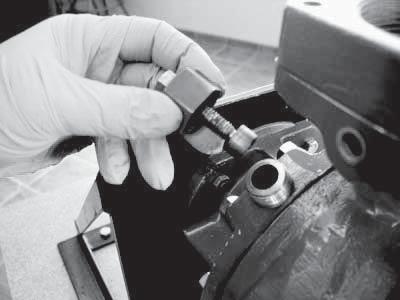
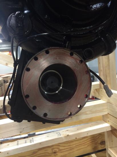
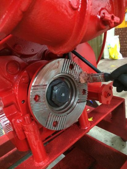
14 DARLEY INSTALLATION OF MECHANICAL FACE SEAL WITH O RING SPECIAL HANDLING Study the engineering layout before installing the seal. This shaft seal is a precision product and should be handled and treated with care. Take special care to prevent scratches on the lapped faces of the primary and mating ring. Provide a very clean work area where the assembly will take place. Clean hands prior to assembly. INSTRUCTION STEPS: Instructions for Installing a Mechanical Shaft Seal 1. Inspect mating ring pocket in seal housing ensuring it is clean, free of chips, and nick free, to provide a proper sealing surface. Isopropyl alcohol may be used to clean the surfaces if required. 2. Inspect the pump shaft surface under the bellows, ensuring it is clean and nick free to provide a proper sealing surface. Isopropyl alcohol may be used to clean surface if required. 3. Lightly lubricate the o-ring on the mating ring with a single drop of P-80 water soluble rubber lubricant (do not over lubricate) and push it into the cavity using the recommended installation tool or other suitable plastic tube free of contaminants, firmly seating the mating ring square. Note: The polished face of the mating ring must face out away from the pump s gear case. Try to not touch the polished sealing face with your fingers; the oils from your fingerprint can cause the seal to leak. Remove any P-80 from the sealing face after installation. The approximate size of a drop should be between the sizes of these two circles. 4. Clean the mating ring surface with isopropyl alcohol to remove any fingerprints and any other contaminants left on mating ring. Prepared by: AAN Rev.: B Approved by: TED 15-1 Date: 11/6/09 Revised by: TED (19July2010)
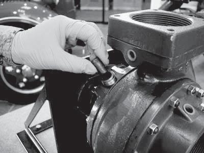
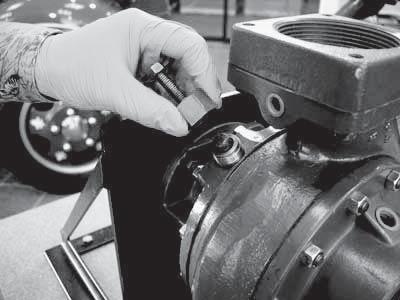
15 Note: Steps 5 9 need to all be completed with in 15 minutes or less. 5. Apply a small drop of P-80 rubber lubricant or water-soluble lubricant (not soapy water) to the inside diameter of the bellows assembly allowing it to be pushed easily into position. 6. Clean the polished sealing face of the primary ring with a clean lint free rag with isopropyl alcohol to remove all fingerprints and other contaminants. 7. Slide a seal save, similar to X6550, over the shaft splines to ensure that the seal is not damaged during installation. Place the primary ring and lubricated bellows assembly (without the spring) on the shaft, using a proper pusher - push the assembly into position so that the seal surfaces are in contact. Remove the seal save from the shaft. The approximate size of a drop should be between the sizes of these two circles. 8. Put the spring in place, seated tight against the spring retainer on the primary ring. Note: Some springs may be slightly tapered, so one end fits the seal better than the other. The end of the spring that best fits the seal should go towards the seal to ensure even spring pressure all the way around. 9. Slide impeller onto impeller shaft, engage the spring into the groove of the impeller hub and install impeller washer, impeller nut, and stainless steel cotter key. ** Reference pump configuration for individual mechanical seal instructions. ** Reference pump assembly drawings and pump assembly tips for further assembly. Note: If the seal leaks slightly after assembly, it may be necessary to run the pump for approximately 30 minutes at psi to rinse out excess lubricant and other contaminants. Once a mechanical seal has been installed, it is recommended that it not be reused. If further information is needed, call DARLEY in Chippewa Falls, WI. at or Prepared by: AAN Rev.: B Approved by: TED 15-2 Date: 11/6/09 Revised by: TED (19July2010)

 to the shaft.")
16 DARLEY BASIC ASSEMBLING TECHNIQUES Work with clean tools in clean surroundings during assembly. Clean parts thoroughly and keep free from nicks and abrasions. Keep loose parts marked otherwise identified to avoid error in assembly. Bearings: Keep bearings in original containers until ready to install. Bearings/Press fits: Clean and oil bearing seats and other parts having press fits to prevent galling. Bearings: When pressing a bearing onto a shaft, the bearing must be started perpendicular (square) to the shaft. Bearings: When pressing bearings onto a shaft all forces applied to the bearing need to be applied to the inner race. Bearings: When pressing bearings into a pocket all forces applied to the bearing need to be applied to the outer race. Bearings: When installing a bearing with one shield, the open side goes toward the oil cavity/gear case. Typically the single shield will be next to an oil seal. OPEN SIDE OF BEARING 1 of 29


17 Bearings: When pressing a bearing onto a shaft, lightly lube the bore of the bearing and the shaft journal for the bearing with oil. Also when installing bearings into bearing pockets, lightly lube the OD of the bearing and the bore of the bearing pocket with oil. Bearings: If necessary to remove a ball bearing from a shaft by forcing against the outer race, the bearing should be discarded and replaced. Press fits: Use suitable machined pushers (The end faces of the pusher should be flat, parallel and burr free) for pressing operations. SUITABLE PUSHERS Press fits: When pressing a part into housing (ex. Stuffing box, seal ring, etc.), the part needs to be started perpendicular to the housing. 2 of 29


18 Press fits: Use a press for forcing press fits whenever possible. If necessary to use a hammer, use one having soft plastic heads. Do not use brass or lead hammers, for the face of the hammer may easily chip or flake, contaminating the assembly, which can cause severe damage to bearings and other precision components. Impeller Nuts: When installing impeller nuts, DO NOT use an impact wrench. Use of impact wrenches has proven to damage the impeller washers, impellers, and impeller shafts. Proper tightening procedure is to bring it snug tight, and then tighten it to the next available cotter pin hole in shaft and notch in the castle nut. Then install stainless steel cotter pin. COTTER PIN HOLE LINED UP WITH NOTCH IN CASTLE NUT STAINLESS STEEL COTTER PIN 3 of 29


19 Lock Washer/Lock Nut: Secure shaft so that it doesn t rotate when tightening lock nut. Line up tab on lock washer with keyway slot in shaft and slide washer onto shaft. Screw lock nut onto shaft until snug, then turn until a tab and slot line up. Using a punch, tap tab from lock washer into slot on lock nut. TAB IN KEYWAY SLOT PROPER FIXTURE TO HOLD SHAFT TAB IN SLOT ON LOCK NUT 4 of 29


20 Loctite/thread locker: When applying Loctite/thread lockers, only use one small drop per hole, unless explicitly told differently by engineering, a WI, or assembly/repair instruction or assembly supervisor. Loctite/thread locker: When applying Loctite/thread lockers to lock fasteners going into captive holes (a hole that is only open on one end), apply the thread locker to the threads of the hole. Loctite/thread locker: When applying Loctite/thread lockers, to lock fasteners that are going to be installed with a pneumatic/power wrench, apply the thread locker to the female threads. Transmission Threads: Use only lock washers on captive holes. The only exception is if it is an aluminum gear case, then use Loctite 243, or equivalent, and no lock washers. Transmission Threads: Use lock washers and Loctite 243, or equivalent, if holes are tapped thru. Inspection Plate Fasteners: Use Loctite 243, or equivalent, on the fasteners that hold the rectangular inspection plate to the side of the transmissions gear case. When installing these fasteners, install all of the fasteners to finger tight, then torque them to a final torque of 72 in.-lbs. in an alternating crossover pattern. Finish here Finish here Start here Start here Fastener Lock Washers and Aluminum: Do not use lock washers against aluminum. Use the appropriate thread locker instead. 5 of 29

21 O-rings/Quad rings: When installing o-rings and quad rings LIGHTLY lube with oil or silicon grease (Dow Corning 111). Be careful not to apply too thick of a film of lubricant when using the silicone grease because over application of the grease can cause the oring/quad ring to bridge and leak. Gear Lube: When filling the gear case with oil, fill with SAE80W/90 gear lube oil to the bottom of the oil level plug on the gear case, or the oil level mark on the dipstick. Maintain the gear case oil level every 25 hours or 3 months, which ever comes first, and change the oil every 50 hours or 6 months. Oil Seal lubrication: When lubricating oil seals prior to installation, apply a minimal amount of SAE 80/W90 oil on the outside diameter of the seal and the sealing lip on the inside diameter of the seal. Do not use any lubricant other than SAE 80W/90 oil unless a Darley document dated after February 14, 2012 specifically calls it out. 6 of 29


22 Yoke nut installation torque for PUC and PUC-3G pumps: Torque PUC and PUC-3G yoke nuts to ft-lb. After the yoke nut has been torqued down, check to make sure the yoke nut engages the yoke face it bumps up against. PUC and PUC-3G yoke nuts are tightened to lb-ft. 7 of 29

23 Yoke nut torque for thread, thread and 7/8-14 thread yoke nuts: Unless otherwise specified, torque interference threaded yoke nuts to ft-lb. Unless otherwise specified, torque all thread yoke nuts to ft-lb. Unless otherwise specified, torque all 7/8-14 interference threaded yoke nuts to 125 ft-lb. After the yoke nut has been torqued down, check to make sure the yoke nut engages the yoke face it bumps up against thread yoke nut Part number shown Needs a 2-1/4 socket to tighten Tighten to ft-lb thread yoke nut Part number shown Needs a 1-7/8 socket to tighten Tighten to ft-lb 7/8-14 thread yoke nut Part number shown Needs a 1-5/16 socket to tighten Tighten to 125 ft-lb thread yoke nuts are typically used on Midship pump thread yoke nuts are typically used on ZSD & ZSP pumps. 7/8-14 thread yoke nuts are used on PTO pumps. 8 of 29

24 All interference threaded yoke nuts are torqued to ft-lb. 9 of 29


25 All threaded yoke nuts are torqued to ft-lb. 10 of 29

26 All 7/8-14 interference thread yoke nuts are tightened to 125 ft-lb. 11 of 29

27 No gaps here After torqueing the yoke nut down, check to make sure there is not a gap between the yoke nut and the yoke. 12 of 29


28 To help with the yoke nut torqueing on midship pumps, shift the transmission into road mode. Put a bar thru the yoke that is not being torqued down to stop the driveline from rotating. Then the driveline will not rotate as the yoke nut is being torqued. To help with tightening yoke nuts on PTO pumps use the tool shown in the above picture. 13 of 29


29 Place the tool over the companion flange as shown above. Make sure to finger tighten a nut on one of the tool s fasteners to secure the tool to the yoke. Now let the tool bump up against a rigid surface and use the torque wrench to tighten the yoke nut as shown above. 14 of 29
30 Recommended fastener tightening torque unless otherwise specified: The following tables will give recommended tightening torques depending upon the fasteners material and if a Loctite type product was used. Use these recommended tightening torques if you are not confident torqueing a fastener. For fasteners that had a Loctite type product applied to their threads, use the K =.20 (Clean non-plated bolt) recommended tightening torque even if either the nut or bolt was zinc electroplated. Best practice is to; use an SAE Grade 8 bolt with an SAE Grade 8 nut, use an SAE Grade 5 bolt with and SAE Grade 5 nut, use an SAE Grade 2 bolt with an SAE Grade 2 nut and use the same bolt material as what the nut is made from. Fastener Size Recommended tightening torque Clamp load #6 32 Grade 8 18 to 27 in-lb 654 to 981 lb #6 40 Grade 8 20 to 30 in-lb 730 to 1,095 lb #8 32 Grade 8 33 to 50 in-lb 1,009 to 1,513 lb #8 36 Grade 8 35 to 52 in-lb 1,060 to 1,591 lb #10 24 Grade 8 48 to 72 in-lb 1,262 to 1,893 lb #10 32 Grade 8 55 to 82 in-lb 1,440 to 2,159 lb ¼ - 20 Grade to 172 in-lb 2,291 to 3,437 lb ¼ - 28 Grade to 196 in-lb 2,619 to 3,928 lb 5/16 18 Grade 8 20 to 29 ft-lb 3,775 to 5,662 lb 5/16 24 Grade 8 22 to 33 ft-lb 4,181 to 6,271 lb 3/8 16 Grade 8 35 to 52 ft-lb 5,579 to 8,369 lb 3/8 24 Grade 8 40 to 59 ft-lb 6,324 to 9,485 lb 7/16 14 Grade 8 56 to 84 ft-lb 7,654 to 11,481 lb 7/16 20 Grade 8 62 to 93 ft-lb 8,548 to 12,821 lb ½ - 13 Grade 8 85 to 128 ft-lb 10,217 to 15,325 lb ½ - 20 Grade 8 96 to 144 ft-lb 11,517 to 17,275 lb 5/8 11 Grade to 254 ft-lb 16,272 to 24,408 lb 5/8 18 Grade to 288 ft-lb 18,429 to 27,643 lb ¾ - 10 Grade to 452 ft-lb 24,081 to 36,122 lb ¾ - 16 Grade to 503 ft-lb 26,853 to 40,280 lb 7/8 9 Grade to 727 ft-lb 33,245 to 49,867 lb 7/8 14 Grade to 802 ft-lb 36,682 to 55,023 lb 1 8 Grade to 1,090 ft-lb 43,614 to 65,421 lb 1 12 Grade to 1,193 ft-lb 47,739 to 71,608 lb The above table is for SAE Grade 8 fasteners, K =.20 (Clean non-plated fasteners or Loctited zinc electroplated fasteners) 15 of 29
31 Fastener Size Recommended tightening torque Clamp load #6 32 Grade 8 20 to 30 in-lb 654 to 981 lb #6 40 Grade 8 22 to 33 in-lb 730 to 1,095 lb #8 32 Grade 8 36 to 55 in-lb 1,009 to 1,513 lb #8 36 Grade 8 38 to 57 in-lb 1,060 to 1,591 lb #10 24 Grade 8 53 to 79 in-lb 1,262 to 1,893 lb #10 32 Grade 8 60 to 90 in-lb 1,440 to 2,159 lb ¼ - 20 Grade to 189 in-lb 2,291 to 3,437 lb ¼ - 28 Grade to 216 in-lb 2,619 to 3,928 lb 5/16 18 Grade 8 22 to 32 ft-lb 3,775 to 5,662 lb 5/16 24 Grade 8 24 to 36 ft-lb 4,181 to 6,271 lb 3/8 16 Grade 8 38 to 58 ft-lb 5,579 to 8,369 lb 3/8 24 Grade 8 43 to 65 ft-lb 6,324 to 9,485 lb 7/16 14 Grade 8 61 to 92 ft-lb 7,654 to 11,481 lb 7/16 20 Grade 8 69 to 103 ft-lb 8,548 to 12,821 lb ½ - 13 Grade 8 94 to 140 ft-lb 10,217 to 15,325 lb ½ - 20 Grade to 158 ft-lb 11,517 to 17,275 lb 5/8 11 Grade to 280 ft-lb 16,272 to 24,408 lb 5/8 18 Grade to 317 ft-lb 18,429 to 27,643 lb ¾ - 10 Grade to 497 ft-lb 24,081 to 36,122 lb ¾ - 16 Grade to 554 ft-lb 26,853 to 40,280 lb 7/8 9 Grade to 800 ft-lb 33,245 to 49,867 lb 7/8 14 Grade to 883 ft-lb 36,682 to 55,023 lb 1 8 Grade to 1,199 ft-lb 43,614 to 65,421 lb 1 12 Grade to 1,313 ft-lb 47,739 to 71,608 lb The above table is for SAE Grade 8 fasteners, K =.22 (Zinc electroplated bolt or nut) 16 of 29
32 Fastener Size Recommended tightening torque Clamp load #6 32 Grade 5 16 to 24 in-lb 589 to 883 lb #6 40 Grade 5 18 to 27 in-lb 657 to 986 lb #8 32 Grade 5 30 to 45 in-lb 908 to 1,362 lb #8 36 Grade 5 31 to 47 in-lb 954 to 1,432 lb #10 24 Grade 5 43 to 65 in-lb 1,136 to 1,704 lb #10 32 Grade 5 49 to 74 in-lb 1,296 to 1,943 lb ¼ - 20 Grade 5 81 to 122 in-lb 1,623 to 2,434 lb ¼ - 28 Grade 5 93 to 139 in-lb 1,855 to 2,783 lb 5/16 18 Grade 5 14 to 21 ft-lb 2,674 to 4,011 lb 5/16 24 Grade 5 15 to 23 ft-lb 2,961 to 4,442 lb 3/8 16 Grade 5 25 to 37 ft-lb 3,952 to 5,928 lb 3/8 24 Grade 5 28 to 42 ft-lb 4,479 to 6,719 lb 7/16 14 Grade 5 40 to 59 ft-lb 5,422 to 8,133 lb 7/16 20 Grade 5 44 to 66 ft-lb 6,055 to 9,082 lb ½ - 13 Grade 5 60 to 90 ft-lb 7,237 to 10,855 lb ½ - 20 Grade 5 68 to 102 ft-lb 8,158 to 12,236 lb 5/8 11 Grade to 180 ft-lb 11,526 to 17,289 lb 5/8 18 Grade to 204 ft-lb 13,054 to 19,581 lb ¾ - 10 Grade to 320 ft-lb 17,057 to 25,586 lb ¾ - 16 Grade to 357 ft-lb 19,021 to 28,532 lb 7/8 9 Grade to 515 ft-lb 23,548 to 35,323 lb 7/8 14 Grade to 568 ft-lb 25,983 to 38,975 lb 1 8 Grade to 772 ft-lb 30,893 to 46,340 lb 1 12 Grade to 845 ft-lb 33,815 to 50,723 lb The above table is for SAE Grade 5 fasteners, K =.20 (Clean non-plated fasteners or Loctited zinc electroplated fasteners) 17 of 29
33 Fastener Size Recommended tightening torque Clamp load #6 32 Grade 5 18 to 27 in-lb 589 to 883 lb #6 40 Grade 5 20 to 30 in-lb 657 to 986 lb #8 32 Grade 5 33 to 49 in-lb 908 to 1,362 lb #8 36 Grade 5 34 to 52 in-lb 954 to 1,432 lb #10 24 Grade 5 47 to 71 in-lb 1,136 to 1,704 lb #10 32 Grade 5 54 to 81 in-lb 1,296 to 1,943 lb ¼ - 20 Grade 5 89 to 134 in-lb 1,623 to 2,434 lb ¼ - 28 Grade to 153 in-lb 1,855 to 2,783 lb 5/16 18 Grade 5 15 to 23 ft-lb 2,674 to 4,011 lb 5/16 24 Grade 5 17 to 25 ft-lb 2,961 to 4,442 lb 3/8 16 Grade 5 27 to 41 ft-lb 3,952 to 5,928 lb 3/8 24 Grade 5 31 to 46 ft-lb 4,479 to 6,719 lb 7/16 14 Grade 5 43 to 65 ft-lb 5,422 to 8,133 lb 7/16 20 Grade 5 49 to 73 ft-lb 6,055 to 9,082 lb ½ - 13 Grade 5 66 to 100 ft-lb 7,237 to 10,855 lb ½ - 20 Grade 5 75 to 112 ft-lb 8,158 to 12,236 lb 5/8 11 Grade to 198 ft-lb 11,526 to 17,289 lb 5/8 18 Grade to 224 ft-lb 13,054 to 19,581 lb ¾ - 10 Grade to 352 ft-lb 17,057 to 25,586 lb ¾ - 16 Grade to 392 ft-lb 19,021 to 28,532 lb 7/8 9 Grade to 567 ft-lb 23,548 to 35,323 lb 7/8 14 Grade to 625 ft-lb 25,983 to 38,975 lb 1 8 Grade to 850 ft-lb 30,893 to 46,340 lb 1 12 Grade to 930 ft-lb 33,815 to 50,723 lb The above table is for SAE Grade 5 fasteners, K =.22 (Zinc electroplated bolt or nut) 18 of 29
34 Fastener Size Recommended tightening torque Clamp load #6 32 Grade 2 8 to 12 in-lb 300 to 450 lb #6 40 Grade 2 9 to 14 in-lb 335 to 502 lb #8 32 Grade 2 15 to 23 in-lb 462 to 693 lb #8 36 Grade 2 16 to 24 in-lb 486 to 729 lb #10 24 Grade 2 22 to 33 in-lb 579 to 868 lb #10 32 Grade 2 25 to 38 in-lb 660 to 990 lb ¼ - 20 Grade 2 53 to 79 in-lb 1,050 to 1,575 lb ¼ - 28 Grade 2 60 to 90 in-lb 1,200 to 1,801 lb 5/16 18 Grade to 162 in-lb 1,730 to 2,595 lb 5/16 24 Grade to 180 in-lb 1,916 to 2,874 lb 3/8 16 Grade 2 16 to 24 ft-lb 2,557 to 3,836 lb 3/8 24 Grade 2 18 to 27 ft-lb 2,898 to 4,347 lb 7/16 14 Grade 2 26 to 38 ft-lb 3,508 to 5,262 lb 7/16 20 Grade 2 29 to 43 ft-lb 3,918 to 5,876 lb ½ - 13 Grade 2 39 to 59 ft-lb 4,683 to 7,024 lb ½ - 20 Grade 2 44 to 66 ft-lb 5,278 to 7,918 lb 5/8 11 Grade 2 78 to 117 ft-lb 7,458 to 11,187 lb 5/8 18 Grade 2 88 to 132 ft-lb 8,447 to 12,670 lb ¾ - 10 Grade to 207 ft-lb 11,037 to 16,556 lb ¾ - 16 Grade to 231 ft-lb 12,308 to 18,462 lb 7/8 9 Grade to 200 ft-lb 9,142 to 13,714 lb 7/8 14 Grade to 221 ft-lb 10,088 to 15,131 lb 1 8 Grade to 300 ft-lb 11,994 to 17,991 lb 1 12 Grade to 328 ft-lb 13,128 to 19,692 lb The above table is for SAE Grade 2 fasteners, K =.20 (Clean non-plated fasteners or Loctited zinc electroplated fasteners) 19 of 29
35 Fastener Size Recommended tightening torque Clamp load #6 32 Grade 2 9 to 14 in-lb 300 to 450 lb #6 40 Grade 2 10 to 15 in-lb 335 to 502 lb #8 32 Grade 2 17 to 25 in-lb 462 to 693 lb #8 36 Grade 2 18 to 26 in-lb 486 to 729 lb #10 24 Grade 2 24 to 36 in-lb 579 to 868 lb #10 32 Grade 2 28 to 41 in-lb 660 to 990 lb ¼ - 20 Grade 2 58 to 87 in-lb 1,050 to 1,575 lb ¼ - 28 Grade 2 66 to 99 in-lb 1,200 to 1,801 lb 5/16 18 Grade to 178 in-lb 1,730 to 2,595 lb 5/16 24 Grade to 198 in-lb 1,916 to 2,874 lb 3/8 16 Grade 2 18 to 26 ft-lb 2,557 to 3,836 lb 3/8 24 Grade 2 20 to 30 ft-lb 2,898 to 4,347 lb 7/16 14 Grade 2 28 to 42 ft-lb 3,508 to 5,262 lb 7/16 20 Grade 2 31 to 47 ft-lb 3,918 to 5,876 lb ½ - 13 Grade 2 43 to 64 ft-lb 4,683 to 7,024 lb ½ - 20 Grade 2 48 to 73 ft-lb 5,278 to 7,918 lb 5/8 11 Grade 2 85 to 128 ft-lb 7,458 to 11,187 lb 5/8 18 Grade 2 97 to 145 ft-lb 8,447 to 12,670 lb ¾ - 10 Grade to 228 ft-lb 11,037 to 16,556 lb ¾ - 16 Grade to 254 ft-lb 12,308 to 18,462 lb 7/8 9 Grade to 220 ft-lb 9,142 to 13,714 lb 7/8 14 Grade to 243 ft-lb 10,088 to 15,131 lb 1 8 Grade to 330 ft-lb 11,994 to 17,991 lb 1 12 Grade to 361 ft-lb 13,128 to 19,692 lb The above table is for SAE Grade 2 fasteners, K =.22 (Zinc electroplated nut or bolt) 20 of 29
36 Fastener Size Recommended tightening torque Clamp load # to 5 in-lb 125 to 188 lb # to 6 in-lb 140 to 210 lb # to 10 in-lb 193 to 290 lb # to 10 in-lb 203 to 305 lb # to 14 in-lb 242 to 363 lb # to 16 in-lb 276 to 414 lb ¼ to 33 in-lb 439 to 659 lb ¼ to 38 in-lb 502 to 753 lb 5/ to 68 in-lb 724 to 1,085 lb 5/ to 75 in-lb 801 to 1,202 lb 3/ to 120 in-lb 1,069 to 1,604 lb 3/ to 136 in-lb 1,212 to 1,818 lb 7/ to 193 in-lb 1,467 to 2,201 lb 7/ to 215 in-lb 1,638 to 2,457 lb ½ to 24 ft-lb 1,958 to 2,937 lb ½ to 28 ft-lb 2,207 to 3,311 lb 5/ to 49 ft-lb 3,119 to 4,678 lb 5/ to 55 ft-lb 3,532 to 5,298 lb ¾ to 87 ft-lb 4,616 to 6,923 lb ¾ to 97 ft-lb 5,147 to 7,720 lb 7/ to 139 ft-lb 6,372 to 9,558 lb 7/ to 154 ft-lb 7,031 to 10,546 lb to 209 ft-lb 8,359 to 12,539 lb to 229 ft-lb 9,150 to 13,725 lb The above table is for Stainless Steel, Bronze or Aluminum fasteners. By fasteners we are implying nuts or bolts not stationary components in the clamped joint. K =.20 (Clean non-plated fasteners with or without a Loctite type product) Socket set screw size Minimum tightening torque for Minimum tightening torque alloy steel socket set screws for stainless socket set screws #6 10 in-lb 7 in-lb #8 19 in-lb 16 in-lb #10 34 in-lb 26 in-lb ¼ 78 in-lb 70 in-lb 5/ in-lb 130 in-lb 3/8 23 ft-lb 230 in-lb 7/16 36 ft-lb 28 ft-lb 1/2 51 ft-lb 42 ft-lb 5/8 110 ft-lb 82 ft-lb 3/4 179 ft-lb 142 ft-lb 7/8 428 ft-lb 333 ft-lb ft-lb 467 ft-lb The above table is the recommended minimum tightening torque for alloy steel and stainless socket set screws. Please note the recommended tightening torque is the same for both fine threaded and coarse threaded set screws 21 of 29
37 For reference, Recommended tightening torque is found by the following equation; T = KDP T = Tightening torque in units of inch-pound. K = Nut factor and it is unit less. D = Nominal bolt diameter in units of inch. P = Clamp load in units of pounds. Nut factor = K =.20 or.22 in these tables. K =.20 for clean non-plated bolts. K =.25 for zinc electroplated bolts. See IFI handbook 6th edition on page M-64 for more details. Our recommended tightening torques is intended to maintain a clamp load of 60% to 90% of the bolt s proof load. See Mechanical Engineering Design ISBN X page 382 for more details. We assumed a Grade 8 proof load of 120,000 psi for all fasteners sizes. We assumed a Grade 5 proof load of 85,000 psi for fasteners ¼ in bolt diameter up to 1 in bolt diameter. We assumed a Grade 5 proof load of 108,000 psi for fasteners #6 up to #10 in bolt diameter. We assumed a Grade 2 proof load of 33,000 psi for fasteners larger than 3/4 in bolt diameter up to 11/2 in bolt diameter. We assumed a Grade 2 proof load of 55,000 psi for fasteners #6 in bolt diameter up to 5/8 in bolt diameter. We assumed a proof load of 23,000 psi for all Stainless Steel, Bronze and Aluminum material fasteners. Sand cast T6 aluminum has a yield strength of 24,000 psi listed in the ASM Specialty Handbook Aluminum and Aluminum Alloys on page 720. Fastener Size #6 32 #6 40 #8 32 #8 36 #10 24 #10 32 ¼ - 20 ¼ / / /8 16 3/8 24 7/ /16 20 ½ - 13 ½ /8 11 5/8 18 ¾ - 10 ¾ /8 9 7/ Nominal bolt diameter (in) Tensile stress area (square inch) Stainless, Brass, Bronze or Aluminum proof load (lb) ,206 1,336 1,782 2,020 2,445 2,730 3,264 3,679 5,198 5,887 7,693 8,578 10,620 11,718 13,932 15, of 29 SAE Grade 2 proof load (lb) ,100 1,750 2,001 2,884 3,194 4,262 4,831 5,847 6,529 7,804 8,797 12,430 14,078 18,395 20,513 15,237 16,813 19,990 21,880 SAE Grade 5 proof load (lb) 981 1,095 1,513 1,591 1,893 2,159 2,705 3,092 4,457 4,936 6,587 7,465 9,036 10,091 12,061 13,596 19,210 21,759 28,429 31,702 39,247 43,305 51,488 56,359 SAE Grade 8 proof load (lb) 1,090 1,217 1,681 1,767 2,104 2,399 3,819 4,365 6,292 6,968 9,299 10,539 12,757 14,246 17,028 19,194 27,120 30,715 40,135 44,755 55,408 61,137 72,689 79,565


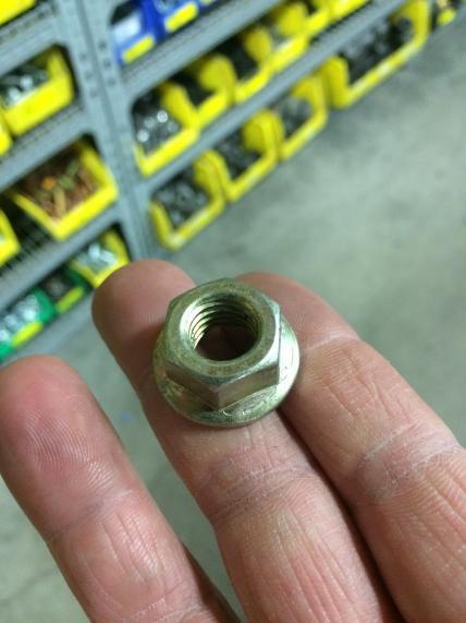
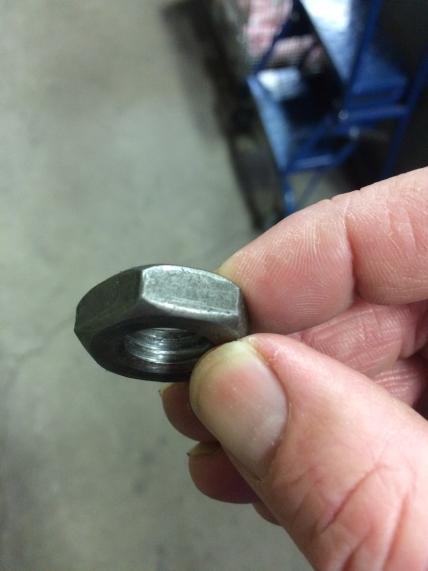
38 The above image shows how SAE Grade 8 hex head bolts can be identified. The above image shows how SAE Grade 8 hex nuts can be identified. The above image shows how SAE Grade 5 hex head bolts can be identified. The above image shows how SAE Grade 5 hex nuts can be identified. The above image shows how SAE Grade 2 hex head bolts can be identified. 23 of 29

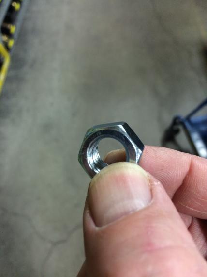
39 The above image shows how SAE Grade 2 hex nuts can be identified. 24 of 29


40 The above images show different types of zinc electroplated fasteners. 25 of 29


41 The above images show different types of clean non-plated fasteners. 26 of 29


42 Zinc electroplated Stainless The bolt on the left is zinc electroplated. The bolt on the right is stainless steel. The above image is a brass machine screw and brass hex nut. 27 of 29


43 All alloy steel socket head cap screws are have an 180,000 psi tensile strength for ½ and smaller bolts and 170,000 psi tensile strength for 5/8 and larger bolts. Use the SAE Grade 8 recommended tightening torque tables for socket head cap screws. All alloy steel socket flat countersunk head cap screws have a 150,000 psi minimum tensile strength. Use the SAE Grade 8 recommended tightening torque tables for alloy steel socket flat countersunk head cap screws. 28 of 29


44 All alloy steel socket button head cap screws have a 137,000 psi minimum tensile strength. Use the SAE Grade 5 recommended tightening torque tables for alloy steel socket button head cap screws.. Alloy Steel Stainless The fasteners on the left are alloy steel socket set screws. The fasteners on the right are stainless socket set screws. If further information is needed, call Darley at Chippewa Falls, WI or of 29
45 W. S. DARLEY & CO. SOME CARE AND HANDLING INSTRUCTIONS 1. DO NOT USE THIS PUMP FOR HOSE TESTING! 2. Avoid unnecessary force and rough handling of parts during disassembly and reassembly. 3. Clean parts thoroughly and maintain free from abrasive foreign matter. 4. Keep bearings in original containers until ready to install. 5. Work with clean tools in clean surroundings during reassembly. 6. Do not bump or abrade machined surfaces, giving special care to wearing surfaces, shaft shoulders, gear and impeller hub faces, gear teeth, etc. 7. Use an arbor press for forcing press fits whenever possible. If necessary to use a hammer, use one having soft plastic heads. 8. Use suitable machined and fitted sleeves or bars for forcing or pressing ball bearings and other parts having press fits. 9. Do not press a ball bearing onto a shaft by forcing against the outer race. Heavy pressure or impact against bearing balls will damage the bearing and cause premature failure. 10. If necessary to remove a ball bearing from a shaft by forcing against the outer race, the bearing should be discarded and replaced. 11. When forcing or pressing a bearing or other part onto a tight fitting shaft, the part must be started square with the shaft and forced on squarely all the way. 12. Clean and oil bearing seats and other parts having press fits to prevent galling. 13. Keep loose parts marked or otherwise identified to avoid errors in assembly. 14. When filling the gearcase with oil, fill it with SAE80W/90 gear lube oil to the bottom of the oil level plug located on the gear case. 15. Maintain the gearcase oil level every 25 hours, or every 3 months which ever comes first, and change the oil every 50 hours, or every 6 months, which ever comes first. IF FURTHER INFORMATION IS NEEDED, CALL W.S. DARLEY & CO. AT CHIPPEWA FALLS, WI. AT or Prepared by: TED Rev.#: 0 Approved by: TED 20.1 Date:
46
W.S. DARLEY & CO. REPAIR SERVICE INSTRUCTIONS TYPE 2 1/2 AGE PORTABLE PUMP PUMP DISASSEMBLY FOR OVERHAUL Refer to Drawing DAC0600
 W.S. DARLEY & CO. REPAIR SERVICE INSTRUCTIONS TYPE 2 1/2 AGE PORTABLE PUMP PUMP DISASSEMBLY FOR OVERHAUL Refer to Drawing DAC0600 1. Remove discharge (73) from pump casing (4). Discard gasket or o ring
 18. KSP 18. KSP 18.1 1200016 1200016 18.2 18.3 1200016 1200016 18.4 18.5 1200016 1200016 18.6 18.7 1200016 1200016 18.8 18.9 1200016 DARLEY BASIC ASSEMBLING TECHNIQUES Work with clean tools in clean surroundings
CP-1, CP-2, CP-2L & CPD-2 Series Overhaul
 Replacement of Mechanical Seals for CM, CMU, CS and CSU Series Pumps Installation Instructions Form No. F-1031 Section 5013 Issue Date 03/01/85 Rev. Date 02/08/11 CP-1, CP-2, CP-2L & CPD-2 Series Overhaul
Overhaul Instructions. S100 Series Centrifugal Fire Pumps. Table of Contents F /22/02 1/19/18
 S100 Series Centrifugal Fire Pumps Overhaul Instructions Form No. F-1031 Section 4219 Issue Date 02/22/02 Rev. Date 1/19/18 Table of Contents Section Page Introduction 4 Ordering Repair Parts 4 Pump Models
CH-4 Series Fire Pumps Overhaul Instructions
 CH-4 Series Fire Pumps Overhaul Instructions Table of Contents Model CHK-4, Transmission Driven (The pump is turned by a K-Series Transmission mounted directly to the pump.) Introduction... 2 Ordering
4.2 WATER PUMP (GEAR CASE MOUNTED AND LATER) (GCM)
 (GCM)") SERIES 60 SERVICE MANUAL 4.2 WATER PUMP (GEAR CASE MOUNTED - 1991 AND LATER) (GCM) The centrifugal-type water pump circulates the engine coolant through the cooling system. The pump is mounted on the rear
SERIES 60 SERVICE MANUAL 4.2 WATER PUMP (GEAR CASE MOUNTED - 1991 AND LATER) (GCM) The centrifugal-type water pump circulates the engine coolant through the cooling system. The pump is mounted on the rear
TC20 Chain Driven Power Take-Off Overhaul Instructions
 TC20 Chain Driven Power Take-Off Overhaul Instructions Table of Contents Section Page Introduction 4 Ordering Repair Parts 4 General Information 5 Special Tools 6 Disassembly See Page 2 Reassembly See
STERNDRIVE UNIT 3 B GEAR HOUSINGS MR/ALPHA ONE/ALPHA ONE SS
 STERNDRIVE UNIT 3 B 23146 GEAR HOUSINGS MR/ALPHA ONE/ALPHA ONE SS Table of Contents Page Identification........................... 3B-1 Specifications.......................... 3B-1 Torque Specifications................
1984 Dodge W250 PICKUP
 1984 Dodge W250 PICKUP Submodel: Engine Type: V8 Liters: 5.2 Fuel Delivery: CARB Fuel: GAS Dana 44 MODELS THROUGH 1984 2. Raise and safely support the vehicle, then remove the wheel hub and bearings as
Maintenance Information
 16573370 Edition 2 February 2014 Air Grinder 99V Series Maintenance Information Save These Instructions Product Safety Information WARNING Failure to observe the following warnings, and to avoid these
DRIVE AXLE Nissan 240SX DESCRIPTION & OPERATION AXLE RATIO & IDENTIFICATION AXLE SHAFT & BEARING R & I DRIVE SHAFT R & I
 DRIVE AXLE 1990 Nissan 240SX 1990 DRIVE AXLES Rear Axle - R200 240SX, 300ZX DESCRIPTION & OPERATION The axle assembly is a hypoid type gear with integral carrier housing. The pinion bearing preload adjustment
REMOVAL & INSTALLATION
 REMOVAL & INSTALLATION CENTER BEARING SUPPORT ASSEMBLY Removal 1. With transmission in neutral and parking brake off, raise vehicle. Scribe alignment marks on all flange/yokes and slip joints to be disassembled
KC Transmission Overhaul
 KC Transmissions Overhaul Instructions Form No. F-1031 Section 4310 Issue Date Rev. Date 02/08/96 12/30/15 Table of Contents Disassembling.............................. 1 Driven Shaft.................................
OPERATION, MAINTENANCE AND OVERHAUL INSTRUCTIONS FOR PB18 SERIES PORTABLE PUMPS
 WATEROUS COMPANY Form No. F 2058 South St. Paul, Minnesota 55075 January, 1992 OPERATION, MAINTENANCE AND OVERHAUL INSTRUCTIONS FOR PB18 SERIES PORTABLE PUMPS Printed in U.S.A. Waterous Company F 2058
1988 Chevrolet Pickup V SUSPENSION - FRONT (4WD)' 'Front Suspension - "V" Series 1988 SUSPENSION - FRONT (4WD) Front Suspension - "V" Series
' 'Front Suspension - V Series 1988 SUSPENSION - FRONT (4WD) Front Suspension - V Series") 1988 SUSPENSION - FRONT (4WD) Front Suspension - "V" Series DESCRIPTION NOTE: Vehicle serial numbers used in this article has been abbreviated for common reference to Chevrolet and GMC models. Chevrolet
1988 SUSPENSION - FRONT (4WD) Front Suspension - "V" Series DESCRIPTION NOTE: Vehicle serial numbers used in this article has been abbreviated for common reference to Chevrolet and GMC models. Chevrolet
CP-1, CP-2, CP-2L & CPD-2 Series Overhaul
 CP-1, CP-2, CP-2L, CPD-2, E301-A and E302-A Series Fire Pumps Overhaul Instructions Form No. F-1031 Section 4205.1 Issue Date 02/88 Rev. Date 01/18/08 Table of Contents Safety Information.................................
Maintenance Information
 45528270 Edition 1 June 2007 Barring Motor T480 Series Maintenance Information Save These Instructions WARNING Always wear eye protection when operating or performing maintenance on this Barring Motor.
Complete Disassembly of Pump. Replacement of Packing or Mechanical Seals Without Disassembling the Pump
 CS/CSU Series Fire Pumps Overhaul Instructions Form No. F-1031 Section 4211 Issue Date 06/30/95 Rev. Date 12/13/17 Table of Contents Type of Overhaul Complete Disassembly of Pump Replacement of Packing
INSTRUCTION AND REPAIR MANUAL MODELS 341A, 342A AND 344A 6
 SECTION 6 ITEM 0 DATED JUNE 1998 SUPERSEDES ITEMS 1, 2, DATED MARCH 1992 INSTRUCTION AND REPAIR MANUAL MODELS 1A, 2A AND A 6 NOTE This repair manual is applicable to pump Models 1A, 2A and A. All photos
Maintenance Information
 80234313 Edition 1 June 2006 Air Grinder, Die Grinder, Sander and Belt Sander Series G1 (Angle) Maintenance Information Save These Instructions WARNING Always wear eye protection when operating or performing
Maintenance Instructions
 General Note These instructions contain information common to more than one model of Bevel Gear Drive. To simplify reading, similar models have been grouped as follows: GROUP 1 Models 11, 0, 1,, (illustrated),,
Transmission Overhaul Procedures-Bench Service
 How to Assemble the Lower Reverse Idler Gear Assembly Special Instructions In 1996 Eaton changed the reverse idler system design. In the nut design, the reverse idler bearing was lubricated through a hole
Maintenance Information
 04581245 Edition 2 May 2014 Air Grinder, Die Grinder and Sander Series G2 (Angle) Maintenance Information Save These Instructions Product Safety Information WARNING Failure to observe the following warnings,
354 CHAPTER EIGHT WATER PUMP
 354 CHAPTER EIGHT 33 Shift handle F : Forward N : Neutral R : Reverse proper alignment of the water tube to the water pump opening during each installation attempt. Make sure the locating pins enter the
PROPELLER SHAFT & DIFFERENTIAL CARRIER SECTIONPD CONTENTS
 PROPELLER SHAFT & DIFFERENTIAL CARRIER SECTIONPD CONTENTS PREPARATION...2 PROPELLER SHAFT...5 On-Vehicle Service...6 Removal and Installation...7 Inspection...7 Disassembly...7 Assembly...8 ON-VEHICLE
Maintenance Information
 80234313 Edition 2 May 2014 Air Grinder, Die Grinder, Sander and Belt Sander Series G1 (Angle) Maintenance Information Save These Instructions Product Safety Information WARNING Failure to observe the
Gear Products Inc N. 161st E. Ave. Tulsa, OK Phone (918) Fax (918)
 Fax (918)") SERVICE MANUAL Disassembly & Assembly Procedures Worm Gear Swing Drive 003 Series Gear Products Inc. 1111 N. 161st E. Ave. Tulsa, OK 74116 Phone (918) 234-3044 Fax (918) 234-3455 Worm Gear Swing Drive
SERVICE MANUAL Disassembly & Assembly Procedures Worm Gear Swing Drive 003 Series Gear Products Inc. 1111 N. 161st E. Ave. Tulsa, OK 74116 Phone (918) 234-3044 Fax (918) 234-3455 Worm Gear Swing Drive
FOR FUTURE REFERENCE SERIES 93HPS
 Hypro Series 93HPS Hydraulically Driven Wetseal Multistage Pumps Repair Manual KEEP FOR FUTURE REFERENCE Form L-1578R Rev. A SERIES 93HPS Hydraulically Driven Stainless Steel Multistage Centrifugal Pumps
Maintenance Information
 16573347 Edition 2 February 2014 Air Grinder Series 88H Maintenance Information Save These Instructions Product Safety Information WARNING Failure to observe the following warnings, and to avoid these
Amarillo PUMP DRIVES (250 HP THROUGH 350 HP) INSTRUCTIONS FOR REPAIRING MODELS 250, 300, and 350
 INSTRUCTIONS FOR REPAIRING MODELS 250, 300, and 350") Amarillo PUMP DRIVES (250 HP THROUGH 350 HP) INSTRUCTIONS FOR REPAIRING MODELS 250, 300, and 350 Amarillo Right Angle Pump Drives, if properly installed and maintained, should provide years of service
Amarillo PUMP DRIVES (250 HP THROUGH 350 HP) INSTRUCTIONS FOR REPAIRING MODELS 250, 300, and 350 Amarillo Right Angle Pump Drives, if properly installed and maintained, should provide years of service
Char-Lynn Hydraulic Motor. Repair Information Series. April, 1997
 Char-Lynn Hydraulic Motor April, 1997 Repair Information Geroler Motors 002 00 004 Parts Drawing 1 See Note 2 Page 1 22 1 9 1-1/4 Split Flange Ports 8 7 6 5 B 1 See Note 2 Page 2 24 4 14 19 20 15 1 18
John Crane Type 5620 and 5620PR Dual O-Ring Cartridge Seal Assembly and Installation Instructions
 I-5620/5620PR-A John Crane Type 5620 and 5620PR Dual O-Ring Cartridge Seal Assembly and Installation Instructions Foreword These instructions are provided to familiarize the user with the seal and its
3.2 DRIVE TORQUE HUB. Roll, Leak and Brake Testing SECTION 3 - CHASSIS & TURNTABLE. 3-2 JLG Lift
 3.2 DRIVE TORQUE HUB Roll, Leak and Brake Testing 10 LUG PATTERN Torque-Hub units should always be roll and leak tested before disassembly and after assembly to make sure that the unit's gears, bearings
DeZURIK " BAW AWWA BUTTERFLY VALVES WITH EPOXY-RETAINED SEAT
 DeZURIK 20 144" BAW AWWA BUTTERFLY VALVES WITH EPOXY-RETAINED SEAT Instruction D10373 April 2017 Instructions These instructions provide information about the 20 (250 F2 model only) and the 24-144 BAW
POWER STEERING PUMP REBUILDING SPK101 Read instructions completely before removal & disassembly
 POWER STEERING PUMP REBUILDING SPK101 Read instructions completely before removal & disassembly DISASSEMBLY: 1. Remove pump from car and allow to drain. 2. Remove pulley from front of pump. This requires
LIMITED SLIP DIFFERENTIAL INSTALLATION
 Installation of the limited slip gear can be done with axle out of car or with car lifted to gain access from underneath. Refer to repair manual for proper lifting instructions if car is to be lifted.
Operator s Manual Table of Contents For Darley PTO Driven JMH Fire Pump
 Operator s Manual Table of Contents For Darley PTO Driven JMH Fire Pump Description, Operation & Maintenance, & Lubrication---------------------------------------------- 1200570 Related Drawings --------------------------------------------------------------------------------------------
Maintenance Information
 45761848 Edition 3 February 2014 Air Die Grinder AC4A, SC4A and XC4A Series Maintenance Information Save These Instructions Product Safety Information WARNING Failure to observe the following warnings,
KP-C Series. Close Coupled End Suction Centrifugal Pumps. Installation, Operation and Maintenance
 KP-C Series Close Coupled End Suction Centrifugal Pumps Installation, Operation and Maintenance PUMP MODEL NOMENCLATURE KP - 8 x 6 x 16 - E C - AI - BCM Pump Series Suction Pipe Size (in) Discharge Pipe
TL (TIL03029) REPAIR MANUAL. Telma model FN72-40 replacement on Arvin Meritor forward tandem carrier. Page 1 of JUL-11.
 REPAIR MANUAL. Telma model FN72-40 replacement on Arvin Meritor forward tandem carrier. Page 1 of JUL-11.") REPAIR MANUAL Telma model FN72-40 replacement on Arvin Meritor forward tandem carrier Page 1 of 10 29-JUL-11 Exploded view P/N: FE962100 Stator Carrier Kit Includes: Qty Description Telma P/N 1 Stator
REPAIR MANUAL Telma model FN72-40 replacement on Arvin Meritor forward tandem carrier Page 1 of 10 29-JUL-11 Exploded view P/N: FE962100 Stator Carrier Kit Includes: Qty Description Telma P/N 1 Stator
SPECIAL TOOLS Dodge Pickup 5.9L Eng R3500. Fig 1: Identifying Remover C-3985-B (Special Tool) 9/6/13 Printer Friendly View
 9/6/13 Printer Friendly View") Procedures 2003 Dodge Pickup 5.9L Eng R3500 manual transmission SPECIAL TOOLS Fig 1: Identifying Remover C-3985-B (Special Tool) www2.prodemand.com/print/index?content=tabs&module=true&tab=true&terms=true&ymms=false&classname=
Procedures 2003 Dodge Pickup 5.9L Eng R3500 manual transmission SPECIAL TOOLS Fig 1: Identifying Remover C-3985-B (Special Tool) www2.prodemand.com/print/index?content=tabs&module=true&tab=true&terms=true&ymms=false&classname=
Mustang Differential Gears - Installation Instructions
 Mustang Differential Gears - Installation Instructions The below installation instructions work for the following products: Ford Racing Gears - 3.73 Gears for 8.8" Ford Rear End Ford Racing Gears - FRPP
Specifications Information and Repair Parts Manual , , , &
 Please read and save this Repair Parts Manual. Read this manual and the General Operating Instructions carefully before attempting to assemble, install, operate or maintain the product described. Protect
Maintenance Information
 16572679 Edition 2 May 2014 Air Drill QP Series Maintenance Information Save These Instructions Product Safety Information WARNING Failure to observe the following warnings, and to avoid these potentially
HYDRAULICS. TX420 & & lower. Hydraulic Tandem Pump Removal. 4. Remove the LH side panel (Fig. 0388).
.") TX420 & 425 240000299 & lower 4. Remove the LH side panel (Fig. 0388). Hydraulic Tandem Pump Removal Note: Cleanliness is a key factor in a successful repair of any hydraulic system. Thoroughly clean all
TX420 & 425 240000299 & lower 4. Remove the LH side panel (Fig. 0388). Hydraulic Tandem Pump Removal Note: Cleanliness is a key factor in a successful repair of any hydraulic system. Thoroughly clean all
TECHNICAL SERVICE MANUAL HEAVY-DUTY BRACKET MOUNTED PUMPS SERIES 120 and SERIES 124 MODELS J, K, KK, L, LQ, LL AND LM
 TECHNICAL SERVICE MANUAL HEAVY-DUTY BRACKET MOUNTED PUMPS SERIES 120 and SERIES 124 MODELS J, K, KK, L, LQ, LL AND LM SECTION 3 BULLETIN TSM-120-124-V ISSUE B-2005 CONTENTS Special Information 2 Maintenance
STERNDRIVE UNIT 3 A DRIVE SHAFT HOUSING
 STERNDRIVE UNIT 3 A 23262 DRIVE SHAFT HOUSING Table of Contents Page Specifications............................ 3A-1 Torque Specifications.................. 3A-1 Upper Drive Shaft Bearing Preload.......
Maintenance Information
 16575128 Edition 2 May 2014 Air Grinder, Sander or Polisher 77A Series Maintenance Information Save These Instructions Product Safety Information Failure to observe the following warnings, and to avoid
DELTA O-RING CARTRIDGE SEAL ASSEMBLY AND INSTALLATION INSTRUCTIONS INTRODUCTION:
 DELTA O-RING CARTRIDGE SEAL ASSEMBLY AND INSTALLATION INSTRUCTIONS INTRODUCTION: These instructions are provided to familiarize the user with the seal and its use. The instructions must be read carefully
MANUAL TRANSAXLE Return to Main Table of Contents
 MANUAL TRANSAXLE Return to Main Table of Contents GENERAL... 2 MANUAL TRANSAXLE CONTROL... 12 SHIFT LEVER ASSEMBLY... 14 MANUAL TRANSAXLE... 15 MANUAL TRANSAXLE ASSEMBLY... 17 FIFTH SPEED SYNCHRONIZER
Kysor On/Off Rear Air Fan Drive
 . Proper precautions must be taken to prevent personal injury from contact with moving parts, unintended engine start, or other hazards present when working with powered equipment. Refer to the vehicle
A/C COMPRESSOR SERVICING Article Text 1991 Saab 9000 For Copyright 1997 Mitchell International Friday, October 15, :22PM
 Article Text ARTICLE BEGINNING 1991 GENERAL SERVICING Compressor Service * PLEASE READ THIS FIRST * CAUTION: When discharging air conditioning system, use only approved refrigerant recovery/recycling equipment.
Vickers. Overhaul Manual. Vane Pumps. Small and Large Series Combination Pumps VC(K)(S)-**-(*)*D*-6(1) VC(K)(S)-**-(*)-*-*D*-5(1)
(S)-**-(*)*D*-6(1) VC(K)(S)-**-(*)-*-*D*-5(1)") Overhaul Manual Vickers Vane Pumps Small and Large Series Combination Pumps VC(K)(S)-**-(*)*D*-6(1) VC(K)(S)-**-(*)-*-*D*-5(1) Revised 12/1/86 I-3150-S Table of Contents Section I. Introduction................................................................................
Overhaul Manual Vickers Vane Pumps Small and Large Series Combination Pumps VC(K)(S)-**-(*)*D*-6(1) VC(K)(S)-**-(*)-*-*D*-5(1) Revised 12/1/86 I-3150-S Table of Contents Section I. Introduction................................................................................
26000 Pump Series Technical Guide
 The Original Engine Cooling Pump Since 1921 www.sherwoodpumps.com 26000 Pump Series Technical Guide Identification G2601-01, G2603-01 Note: G2603-01 has an integrated cam. (There is no cam screw as the
TECHNICAL SERVICE MANUAL
 TECHNICAL SERVICE MANUAL ABRASIVE LIQUID HEAVY-DUTY BRACKET MOUNTED PUMPS SERIES 4625 SIZES H - M SECTION TSM 410.2 PAGE 1 of 10 ISSUE C CONTENTS Introduction....................... 1 Special Information...................
Technical Bulletin
 Page # 1 2 3 Technical Bulletin --------------------------------------------------------------------------------- 1202510 4 5-6 Seal Installation Instructions --------------------------------------------------------------------
DIFFERENTIALS & AXLE SHAFTS
 DIFFERENTIALS & AXLE SHAFTS 2001 Chevrolet Camaro 2000-01 DRIVE AXLES General Motors Differentials & Axle Shafts Chevrolet; Camaro Pontiac; Firebird DESCRIPTION & OPERATION Drive axle is a semi-floating,
PB18 SERIES PORTABLE PUMPS
 PB18 SERIES PORTABLE PUMPS OPERATION, MAINTENANCE AND OVERHAUL INSTRUCTIONS MODELS: PB18-G2015B PB18-2515 PB18-2515B PB18-3030 PB18-3030C WATEROUS COMPANY SOUTH ST. PAUL, MINNESOTA 55075 U.S.A. SAFETY
Parts List Single Reduction Models, Cast Iron Units
 Parts List Single Reduction Models, Cast Iron Units 60 51 51 10 24 11 11 9 24 12 19 17 27 31 8 23 7 14 20 28 26 5 1 2 6 44 60 50 23 7 6 30 27 30 4 3 30 13 29 14 22 18 27 43 48 50 8 15 16 12 25 9 51 51
DELTA O-RING CARTRIDGE SEAL ASSEMBLY AND INSTALLATION INSTRUCTIONS INTRODUCTION:
 DELTA O-RING CARTRIDGE SEAL ASSEMBLY AND INSTALLATION INSTRUCTIONS INTRODUCTION: These instructions are provided to familiarize the user with the seal and its use. The instructions must be read carefully
This file is available for free download at
 This file is available for free download at http://www.iluvmyrx7.com This file is fully text-searchable select Edit and Find and type in what you re looking for. This file is intended more for online viewing
MAINTENANCE AND REPAIR INSTRUCTIONS
 MAINTENANCE AND REPAIR INSTRUCTIONS TYPE TH PUMPS Peerless Pump Company Indianapolis IN, 46207-7026 4849357 TABLE OF CONTENTS Maintenance Page 1 & 2 Disassembly Page 5 & 6 Impeller Clearance 3 Reassembly
Service Manual. #19 Gearmatic Winch
 Allis Chalmers Service Manual #19 Gearmatic Winch Service Manual THIS IS A MANUAL PRODUCED BY JENSALES INC. WITHOUT THE AUTHORIZATION OF ALLIS CHALMERS OR IT S SUCCESSORS. ALLIS CHALMERS AND IT S SUCCESSORS
Operator s Manual Table of Contents For Darley PTO Driven KSPAH Fire Pump
 Operator s Manual Table of Contents For Darley PTO Driven KSPAH Fire Pump Description, Operation & Maintenance, & Lubrication---------------------------------------------- 1200563 Related Drawings -------------------------------------------------------------------------------------------
1999 F-150/250 Workshop Manual
 Page 1 of 30 SECTION 205-03: Front Drive Axle/Differential Ford 8.8-Inch Ring Gear 1999 F-150/250 Workshop Manual DISASSEMBLY AND ASSEMBLY Procedure revision date: 01/08/2003 Axle Front Drive Special Tool(s)
2002 F-Super Duty /Excursion Workshop Manual
 Page 1 of 25 SECTION 307-01: Automatic Transaxle/Transmission 2002 F-Super Duty 250-550/Excursion Workshop Manual ASSEMBLY Procedure revision date: 05/23/2001 Transmission Special Tool(s) Remover, O-Ring
INSTALLATION, OPERATION, MAINTENANCE MANUAL FOR MANUALLY OPERATED STOP CHECK VALVE
 INSTALLATION, OPERATION, MAINTENANCE MANUAL FOR MANUALLY OPERATED STOP CHECK VALVE Page 1 of 13 1.1 General CHAPTER 1 - GENERAL INFORMATION This manual contains maintenance instructions with pertinent
TECHNICAL BULLETIN. Yoke Removal and Installation Procedure for Meritor Drive Axles. Remove the Yoke and Pinion Seal WARNING CAUTION CAUTION.
 Issued 11-99 TECHNICAL BULLETIN Yoke Removal and Installation Procedure for Meritor Drive Axles Remove the Yoke and Pinion Seal Figure 1 WARNING Park the vehicle on a level surface. Block the wheels to
REMOVAL & INSTALLATION
 REMOVAL & INSTALLATION AXLE SHAFTS & BEARINGS Removal CAUTION: Failure to turn off air suspension power before raising vehicle may result in unexpected inflation or deflation of air springs. DO NOT reconnect
Maintenance Information
 16573321 Edition 3 February 2014 Air Grinder Series 61H Maintenance Information Save These Instructions Product Safety Information WARNING Failure to observe the following warnings, and to avoid these
Fluid-O-Tech ROTOFLOW ROTARY VANE PUMP REBUILD MANUAL
 Fluid-O-Tech PUMP TECHNOLOGY AT ITS BEST WWW.FLUID-O-TECH.COM Office: 161 Atwater St., Plantsville, CT 06479 Phone: (860) 276-9270 Fax: (860) 620-0193 ROTOFLOW ROTARY VANE PUMP REBUILD MANUAL 08/09 Ed.,
Instruction Manual for HSPA Take-Up Units
 Installation Instruction Manual for HSPA Take-Up Units Warning: To ensure the drive is not unexpectedly started, turn off and lockout the power source before proceeding. Failure to observe these precautions
Second Stage Regulator - 1/4 Turn
 Second Stage Regulator - 1/4 Turn MAINTENANCE AND REPAIR TAL 806 (L) Rev. 6 MSA 2008 Prnt. Spec. 10000005389 (I) Mat. 10042827 Doc. 10000015245 1/4 TURN SECOND STAGE REGULATOR SECOND STAGE REGULATOR COMPONENTS
Input Adjusting Ring Leak Repair Procedure for Meritor MT-14X Series Forward Differential Carriers
 Revised 01-16 Technical Bulletin Input Adjusting Ring Leak Repair Procedure for Meritor MT-14X Series Forward Differential Carriers Revised 1 Technical 01- Bulletin 16 Hazard Alert Messages Read and observe
Installation Vertical Pump: Installation 'CM' and 'CDM' Style: Operation:
 Installation Vertical Pump: Gusher vertical end suction pumps with integral shaft is easily installed and put into service. With the one piece shaft design there is no couplings to align, no shims or no
Introduction. Pressed Shaft Flowmeter. Flowmeter Service Kits. Disassembly. Idler Shaft Removal
 Flowmeter Service Kits Introduction See Figure. This instruction sheet provides repair procedures for flowmeters that use either pressed or screw-in shafts. Refer to the applicable repair procedure: Pressed
SERVICE MANUAL L130B / L4130 Series Logstacker Drive Axle With Bolt-On Stub End Retainer
 SERVICE MANUAL L130B / L4130 Series Logstacker Drive Axle With Bolt-On Stub End Retainer Page 1 Allied Form #80-930 Rev 07/2009 SERVICE MANUAL LOG STACKER DA202 DRIVE AXLE TABLE OF CONTENTS PROCEDURE FOR
Auto mo tive Cor po ra tion TC 237 TRANSFER CASE SERVICE MAN UAL. Fabco Automotive Corporation Livermore, CA
 Auto mo tive Cor po ra tion TC 237 TRANSFER CASE SERVICE MAN UAL Fabco Automotive Corporation Livermore, CA TABLE OF CONTENTS Introduction and Specifications 3 Front View 4 Rear View 5 Lubrication Types
3M Overhaul Service Kit
 SERVICE INSTRUCTIONS FOR 3M 12,000 RPM 5 in. (127 mm) and 6 in. (150 mm) RANDOM ORBITAL SANDERS 3M Overhaul Service Kit The part number 20347, 3M Overhaul Service Kit, contains all the replacement parts
225 CARTRIDGE DUAL SEAL
 225 CARTRIDGE DUAL SEAL MECHANICAL SEAL INSTALLATION INSTRUCTIONS PREPARATION 1 2 500.010" 0,25 mm 3 4.32 µ" 0,8 µm R a 1000 + ±.001".002" 0,025mm 0,050mm CAUTIONS These instructions are general in nature.
TECHNICAL SERVICE MANUAL
 TECHNICAL SERVICE MANUAL VIKING HELICAL GEAR REDUCERS "A", "B", AND "C" SIZES SECTION TSM 610 PAGE 1 OF 9 ISSUE E CONTENTS Special Information 2 Lubrication 2 Installation 3 Operation 3 Disassembly 3 Assembly
REFILL STATION REBUILD KIT P/N 14270NOS
 REFILL STATION REBUILD KIT P/N 14270NOS INSTRUCTION SHEET P/N 199R10338 1.0 DISASSEMBLY This procedure describes the removal of the air module from the fluid module and complete disassembly of the pump.
AMARILLO PUMP DRIVES MODEL 1 OOOA, 1200, 1500, 1800
 AMARILLO PUMP DRIVES MODEL 1 OOOA, 1200, 1500, 1800 INSTRUCTIONS FOR REPAIRING MARCH 1, 1993 AMARILLO GEAR COMPANY Post Office Box 1789, Amarillo, Texas 79105 806 / 622-1273 FAX 806 / 622-3258 INSTRUCTIONS
255 Cartridge Dual Seal
 MECHANICAL SEAL INSTALLATION INSTRUCTIONS 255 Cartridge Dual Seal Installation Instructions SEAL INSTALLATION Preparation Determine if the pump is in good condition. A. Check the shaft or sleeve. 1. Remove
SECTION Front Drive Axle/Differential
 205-03-i Front Drive Axle/Differential 205-03-i SECTION 205-03 Front Drive Axle/Differential CONTENTS PAGE Axle... 205-03-2 205-03-2 Front Drive Axle/Differential 205-03-2 Axle Special Tool(s) C-Frame
Ampco ZP1 Series. Positive Displacement Pumps Installation and Maintenance Manual
 Ampco ZP1 Series Positive Displacement Pumps Installation and Maintenance Manual Table of Contents Introduction... 3 Introduction... 3 Ampco Pump Company Warranty... 3 General Information... 3 Shipping
18000 Pump Series Technical Guide
 The Original Engine Cooling Pump Since 1921 www.sherwoodpumps.com 18000 Pump Series Technical Guide Identification G1801 and G1805 G1807 and G18071-01 G1804, G1806 and G18061-01 G1811-01 G1808, G18081-01,
3M Overhaul Service Kit
 SERVICE INSTRUCTIONS FOR 3M 12,000 RPM 3 in. (77 mm) RANDOM ORBITAL SANDERS 3M Overhaul Service Kit The part number 20346, 3M Overhaul Service Kit, contains all the replacement parts that naturally wear
DRIVE AXLE - INTEGRAL HOUSING
 DRIVE AXLE - INTEGRAL HOUSING 1993 Toyota Celica 1993 DRIVE AXLES Toyota Differentials & Axle Shafts - Integral Housing Toyota; Celica All-Trac DESCRIPTION Drive axle assembly is a hypoid type with integral
Maintenance Information
 Form 16573321 Edition 1 July 2004 Air Grinder Series 61H Maintenance Information Save These Instructions Always wear eye protection when operating or performing maintenance on this tool. Always turn off
ASSEMBLY INSTRUCTIONS
 ASSEMBLY INSTRUCTIONS FOR FORGED SUPERLITE BIG BRAKE FRONT HUB KIT WITH 3.00 DIAMETER VENTED ROTOR 968-969 FORD MUSTANG (DISC BRAKE SPINDLE ONLY) PART NUMBER GROUP 0-950 WARNING INSTALLATION OF THIS KIT
2001 Dodge RAM 3500 PICKUP
 1 of 76 9/14/2012 7:02 PM 2001 Dodge RAM 3500 PICKUP Submodel: Engine Type: L6 Liters: 5.9 Fuel Delivery: FI Fuel: DIESEL Subarticles MANUAL- NV3500 - DISASSEMBLY MANUAL- NV3500 - DISASSEMBLY MANUAL -
Maintenance. Daily. Shutdown Procedure. Periodically. During Freezing Temperatures
 Maintenance Daily Check the oil level and the condition of the oil. When the pump is operating, the oil in the pump housing gets warm and expands, filling into the oil reservoir. Depending on the type
Transmission Overhaul Procedures-Bench Service
 How to Install the Auxiliary Countershaft Assembly Special Instructions To make auxiliary section assembly easier, you can make an auxiliary section fixture out of a 2" x 12" piece of wood. 3' 1' 3" 4.56"
PRODUCT SERVICE MANUAL FOR CIG Lip Seal Double Pumps
 PRODUCT SERVICE MANUAL FOR CIG Lip Seal Double Pumps WARNING The Imo General Installation Operation, Maintenance, and Troubleshooting Manual, (No. SRM00046), as well as all other component manuals supplied
4410 TwinHydrostatic Gas Seal
 IS0 9001 CERTIFIED CHESTERTON FLUID SEALING DIVISION INSTALLATION INSTRUCTIONS 4410 TwinHydrostatic Gas Seal SEAL INSTALLATION Preparation Determine if the pump is in good condition. A. Check the shaft
INSTALLATION AND MAINTENANCE MANUAL
 TYPE 2 PTO INSTALLATION AND MAINTENANCE MANUAL P.O. Box 8148 Wichita Falls, Texas 76307 1600 Fisher Rd. Wichita Falls, Texas 76305 Phone: (940) 7611971 Fax: (940) 7611989 www.wptpower.com email: info@wptpower.com
250L Cartridge Dual Seal
 INSTALLATION, OPERATION AND MAINTENANCE INSTRUCTIONS 250L Cartridge Dual Seal Installation, Operation and Maintenance Instructions TABLE OF CONTENTS 1.0 Cautions...2 2.0 Transport and Storage...2 3.0 Description...2
OPERATION AND MAINTENANCE INSTRUCTIONS
 OPERATION AND MAINTENANCE INSTRUCTIONS 334 SERIES THREE-PIECE BALL VALVES 1/4 to 2-1/2 Installation and Operation Always install your valve according to accepted industry standards and practices and operate
Kysor On/Off Rear Air Fan Drive
 . Proper precautions must be taken to prevent personal injury from contact with moving parts, unintended engine start or other hazards present when working with powered equipment. Refer to the vehicle