|
|
|
- Martina Thornton
- 5 years ago
- Views:
Transcription
1 18. KSP 18. KSP
2
3
4
5
6
7
8

9

10

 to the shaft.")
11 DARLEY BASIC ASSEMBLING TECHNIQUES Work with clean tools in clean surroundings during assembly. Clean parts thoroughly and keep free from nicks and abrasions. Keep loose parts marked otherwise identified to avoid error in assembly. Bearings: Keep bearings in original containers until ready to install. Bearings/Press fits: Clean and oil bearing seats and other parts having press fits to prevent galling. Bearings: When pressing a bearing onto a shaft, the bearing must be started perpendicular (square) to the shaft. Bearings: When pressing bearings onto a shaft all forces applied to the bearing need to be applied to the inner race. Bearings: When pressing bearings into a pocket all forces applied to the bearing need to be applied to the outer race. Bearings: When installing a bearing with one shield, the open side goes toward the oil cavity/gear case. Typically the single shield will be next to an oil seal. OPEN SIDE OF BEARING 1 of 29


12 Bearings: When pressing a bearing onto a shaft, lightly lube the bore of the bearing and the shaft journal for the bearing with oil. Also when installing bearings into bearing pockets, lightly lube the OD of the bearing and the bore of the bearing pocket with oil. Bearings: If necessary to remove a ball bearing from a shaft by forcing against the outer race, the bearing should be discarded and replaced. Press fits: Use suitable machined pushers (The end faces of the pusher should be flat, parallel and burr free) for pressing operations. SUITABLE PUSHERS Press fits: When pressing a part into housing (ex. Stuffing box, seal ring, etc.), the part needs to be started perpendicular to the housing. 2 of 29


13 Press fits: Use a press for forcing press fits whenever possible. If necessary to use a hammer, use one having soft plastic heads. Do not use brass or lead hammers, for the face of the hammer may easily chip or flake, contaminating the assembly, which can cause severe damage to bearings and other precision components. Impeller Nuts: When installing impeller nuts, DO NOT use an impact wrench. Use of impact wrenches has proven to damage the impeller washers, impellers, and impeller shafts. Proper tightening procedure is to bring it snug tight, and then tighten it to the next available cotter pin hole in shaft and notch in the castle nut. Then install stainless steel cotter pin. COTTER PIN HOLE LINED UP WITH NOTCH IN CASTLE NUT STAINLESS STEEL COTTER PIN 3 of 29


14 Lock Washer/Lock Nut: Secure shaft so that it doesn t rotate when tightening lock nut. Line up tab on lock washer with keyway slot in shaft and slide washer onto shaft. Screw lock nut onto shaft until snug, then turn until a tab and slot line up. Using a punch, tap tab from lock washer into slot on lock nut. TAB IN KEYWAY SLOT PROPER FIXTURE TO HOLD SHAFT TAB IN SLOT ON LOCK NUT 4 of 29


15 Loctite/thread locker: When applying Loctite/thread lockers, only use one small drop per hole, unless explicitly told differently by engineering, a WI, or assembly/repair instruction or assembly supervisor. Loctite/thread locker: When applying Loctite/thread lockers to lock fasteners going into captive holes (a hole that is only open on one end), apply the thread locker to the threads of the hole. Loctite/thread locker: When applying Loctite/thread lockers, to lock fasteners that are going to be installed with a pneumatic/power wrench, apply the thread locker to the female threads. Transmission Threads: Use only lock washers on captive holes. The only exception is if it is an aluminum gear case, then use Loctite 243, or equivalent, and no lock washers. Transmission Threads: Use lock washers and Loctite 243, or equivalent, if holes are tapped thru. Inspection Plate Fasteners: Use Loctite 243, or equivalent, on the fasteners that hold the rectangular inspection plate to the side of the transmissions gear case. When installing these fasteners, install all of the fasteners to finger tight, then torque them to a final torque of 72 in.-lbs. in an alternating crossover pattern. Finish here Finish here Start here Start here Fastener Lock Washers and Aluminum: Do not use lock washers against aluminum. Use the appropriate thread locker instead. 5 of 29

16 O-rings/Quad rings: When installing o-rings and quad rings LIGHTLY lube with oil or silicon grease (Dow Corning 111). Be careful not to apply too thick of a film of lubricant when using the silicone grease because over application of the grease can cause the oring/quad ring to bridge and leak. Gear Lube: When filling the gear case with oil, fill with SAE80W/90 gear lube oil to the bottom of the oil level plug on the gear case, or the oil level mark on the dipstick. Maintain the gear case oil level every 25 hours or 3 months, which ever comes first, and change the oil every 50 hours or 6 months. Oil Seal lubrication: When lubricating oil seals prior to installation, apply a minimal amount of SAE 80/W90 oil on the outside diameter of the seal and the sealing lip on the inside diameter of the seal. Do not use any lubricant other than SAE 80W/90 oil unless a Darley document dated after February 14, 2012 specifically calls it out. 6 of 29


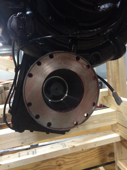
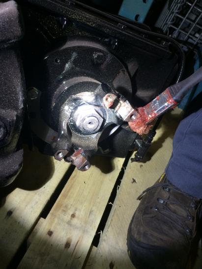
17 Yoke nut installation torque for PUC and PUC-3G pumps: Torque PUC and PUC-3G yoke nuts to ft-lb. After the yoke nut has been torqued down, check to make sure the yoke nut engages the yoke face it bumps up against. PUC and PUC-3G yoke nuts are tightened to lb-ft. 7 of 29

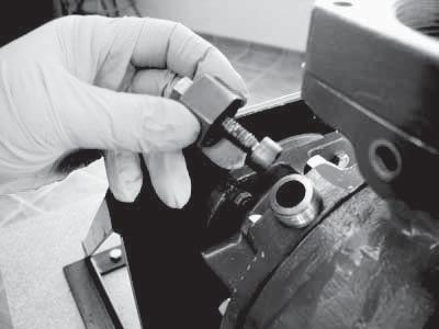
18 Yoke nut torque for thread, thread and 7/8-14 thread yoke nuts: Unless otherwise specified, torque interference threaded yoke nuts to ft-lb. Unless otherwise specified, torque all thread yoke nuts to ft-lb. Unless otherwise specified, torque all 7/8-14 interference threaded yoke nuts to 125 ft-lb. After the yoke nut has been torqued down, check to make sure the yoke nut engages the yoke face it bumps up against thread yoke nut Part number shown Needs a 2-1/4 socket to tighten Tighten to ft-lb thread yoke nut Part number shown Needs a 1-7/8 socket to tighten Tighten to ft-lb 7/8-14 thread yoke nut Part number shown Needs a 1-5/16 socket to tighten Tighten to 125 ft-lb thread yoke nuts are typically used on Midship pump thread yoke nuts are typically used on ZSD & ZSP pumps. 7/8-14 thread yoke nuts are used on PTO pumps. 8 of 29

19 All interference threaded yoke nuts are torqued to ft-lb. 9 of 29


20 All threaded yoke nuts are torqued to ft-lb. 10 of 29

21 All 7/8-14 interference thread yoke nuts are tightened to 125 ft-lb. 11 of 29

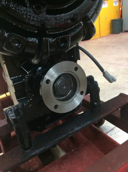
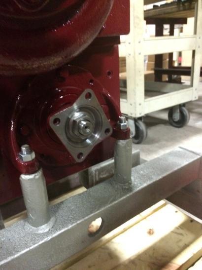
22 No gaps here After torqueing the yoke nut down, check to make sure there is not a gap between the yoke nut and the yoke. 12 of 29


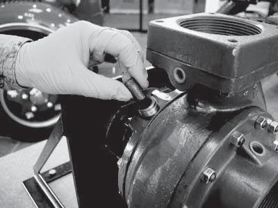
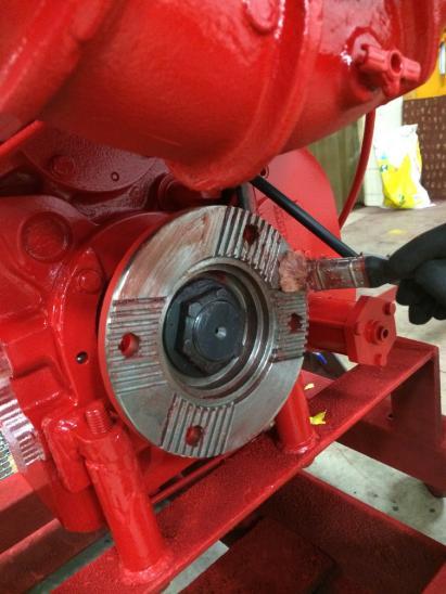
23 To help with the yoke nut torqueing on midship pumps, shift the transmission into road mode. Put a bar thru the yoke that is not being torqued down to stop the driveline from rotating. Then the driveline will not rotate as the yoke nut is being torqued. To help with tightening yoke nuts on PTO pumps use the tool shown in the above picture. 13 of 29


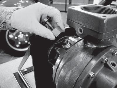
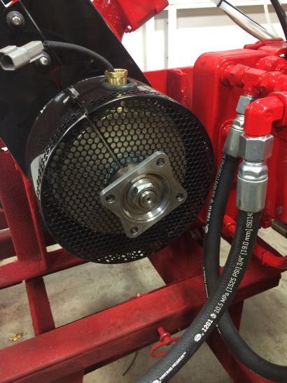
24 Place the tool over the companion flange as shown above. Make sure to finger tighten a nut on one of the tool s fasteners to secure the tool to the yoke. Now let the tool bump up against a rigid surface and use the torque wrench to tighten the yoke nut as shown above. 14 of 29
25 Recommended fastener tightening torque unless otherwise specified: The following tables will give recommended tightening torques depending upon the fasteners material and if a Loctite type product was used. Use these recommended tightening torques if you are not confident torqueing a fastener. For fasteners that had a Loctite type product applied to their threads, use the K =.20 (Clean non-plated bolt) recommended tightening torque even if either the nut or bolt was zinc electroplated. Best practice is to; use an SAE Grade 8 bolt with an SAE Grade 8 nut, use an SAE Grade 5 bolt with and SAE Grade 5 nut, use an SAE Grade 2 bolt with an SAE Grade 2 nut and use the same bolt material as what the nut is made from. Fastener Size Recommended tightening torque Clamp load #6 32 Grade 8 18 to 27 in-lb 654 to 981 lb #6 40 Grade 8 20 to 30 in-lb 730 to 1,095 lb #8 32 Grade 8 33 to 50 in-lb 1,009 to 1,513 lb #8 36 Grade 8 35 to 52 in-lb 1,060 to 1,591 lb #10 24 Grade 8 48 to 72 in-lb 1,262 to 1,893 lb #10 32 Grade 8 55 to 82 in-lb 1,440 to 2,159 lb ¼ - 20 Grade to 172 in-lb 2,291 to 3,437 lb ¼ - 28 Grade to 196 in-lb 2,619 to 3,928 lb 5/16 18 Grade 8 20 to 29 ft-lb 3,775 to 5,662 lb 5/16 24 Grade 8 22 to 33 ft-lb 4,181 to 6,271 lb 3/8 16 Grade 8 35 to 52 ft-lb 5,579 to 8,369 lb 3/8 24 Grade 8 40 to 59 ft-lb 6,324 to 9,485 lb 7/16 14 Grade 8 56 to 84 ft-lb 7,654 to 11,481 lb 7/16 20 Grade 8 62 to 93 ft-lb 8,548 to 12,821 lb ½ - 13 Grade 8 85 to 128 ft-lb 10,217 to 15,325 lb ½ - 20 Grade 8 96 to 144 ft-lb 11,517 to 17,275 lb 5/8 11 Grade to 254 ft-lb 16,272 to 24,408 lb 5/8 18 Grade to 288 ft-lb 18,429 to 27,643 lb ¾ - 10 Grade to 452 ft-lb 24,081 to 36,122 lb ¾ - 16 Grade to 503 ft-lb 26,853 to 40,280 lb 7/8 9 Grade to 727 ft-lb 33,245 to 49,867 lb 7/8 14 Grade to 802 ft-lb 36,682 to 55,023 lb 1 8 Grade to 1,090 ft-lb 43,614 to 65,421 lb 1 12 Grade to 1,193 ft-lb 47,739 to 71,608 lb The above table is for SAE Grade 8 fasteners, K =.20 (Clean non-plated fasteners or Loctited zinc electroplated fasteners) 15 of 29
26 Fastener Size Recommended tightening torque Clamp load #6 32 Grade 8 20 to 30 in-lb 654 to 981 lb #6 40 Grade 8 22 to 33 in-lb 730 to 1,095 lb #8 32 Grade 8 36 to 55 in-lb 1,009 to 1,513 lb #8 36 Grade 8 38 to 57 in-lb 1,060 to 1,591 lb #10 24 Grade 8 53 to 79 in-lb 1,262 to 1,893 lb #10 32 Grade 8 60 to 90 in-lb 1,440 to 2,159 lb ¼ - 20 Grade to 189 in-lb 2,291 to 3,437 lb ¼ - 28 Grade to 216 in-lb 2,619 to 3,928 lb 5/16 18 Grade 8 22 to 32 ft-lb 3,775 to 5,662 lb 5/16 24 Grade 8 24 to 36 ft-lb 4,181 to 6,271 lb 3/8 16 Grade 8 38 to 58 ft-lb 5,579 to 8,369 lb 3/8 24 Grade 8 43 to 65 ft-lb 6,324 to 9,485 lb 7/16 14 Grade 8 61 to 92 ft-lb 7,654 to 11,481 lb 7/16 20 Grade 8 69 to 103 ft-lb 8,548 to 12,821 lb ½ - 13 Grade 8 94 to 140 ft-lb 10,217 to 15,325 lb ½ - 20 Grade to 158 ft-lb 11,517 to 17,275 lb 5/8 11 Grade to 280 ft-lb 16,272 to 24,408 lb 5/8 18 Grade to 317 ft-lb 18,429 to 27,643 lb ¾ - 10 Grade to 497 ft-lb 24,081 to 36,122 lb ¾ - 16 Grade to 554 ft-lb 26,853 to 40,280 lb 7/8 9 Grade to 800 ft-lb 33,245 to 49,867 lb 7/8 14 Grade to 883 ft-lb 36,682 to 55,023 lb 1 8 Grade to 1,199 ft-lb 43,614 to 65,421 lb 1 12 Grade to 1,313 ft-lb 47,739 to 71,608 lb The above table is for SAE Grade 8 fasteners, K =.22 (Zinc electroplated bolt or nut) 16 of 29
27 Fastener Size Recommended tightening torque Clamp load #6 32 Grade 5 16 to 24 in-lb 589 to 883 lb #6 40 Grade 5 18 to 27 in-lb 657 to 986 lb #8 32 Grade 5 30 to 45 in-lb 908 to 1,362 lb #8 36 Grade 5 31 to 47 in-lb 954 to 1,432 lb #10 24 Grade 5 43 to 65 in-lb 1,136 to 1,704 lb #10 32 Grade 5 49 to 74 in-lb 1,296 to 1,943 lb ¼ - 20 Grade 5 81 to 122 in-lb 1,623 to 2,434 lb ¼ - 28 Grade 5 93 to 139 in-lb 1,855 to 2,783 lb 5/16 18 Grade 5 14 to 21 ft-lb 2,674 to 4,011 lb 5/16 24 Grade 5 15 to 23 ft-lb 2,961 to 4,442 lb 3/8 16 Grade 5 25 to 37 ft-lb 3,952 to 5,928 lb 3/8 24 Grade 5 28 to 42 ft-lb 4,479 to 6,719 lb 7/16 14 Grade 5 40 to 59 ft-lb 5,422 to 8,133 lb 7/16 20 Grade 5 44 to 66 ft-lb 6,055 to 9,082 lb ½ - 13 Grade 5 60 to 90 ft-lb 7,237 to 10,855 lb ½ - 20 Grade 5 68 to 102 ft-lb 8,158 to 12,236 lb 5/8 11 Grade to 180 ft-lb 11,526 to 17,289 lb 5/8 18 Grade to 204 ft-lb 13,054 to 19,581 lb ¾ - 10 Grade to 320 ft-lb 17,057 to 25,586 lb ¾ - 16 Grade to 357 ft-lb 19,021 to 28,532 lb 7/8 9 Grade to 515 ft-lb 23,548 to 35,323 lb 7/8 14 Grade to 568 ft-lb 25,983 to 38,975 lb 1 8 Grade to 772 ft-lb 30,893 to 46,340 lb 1 12 Grade to 845 ft-lb 33,815 to 50,723 lb The above table is for SAE Grade 5 fasteners, K =.20 (Clean non-plated fasteners or Loctited zinc electroplated fasteners) 17 of 29
28 Fastener Size Recommended tightening torque Clamp load #6 32 Grade 5 18 to 27 in-lb 589 to 883 lb #6 40 Grade 5 20 to 30 in-lb 657 to 986 lb #8 32 Grade 5 33 to 49 in-lb 908 to 1,362 lb #8 36 Grade 5 34 to 52 in-lb 954 to 1,432 lb #10 24 Grade 5 47 to 71 in-lb 1,136 to 1,704 lb #10 32 Grade 5 54 to 81 in-lb 1,296 to 1,943 lb ¼ - 20 Grade 5 89 to 134 in-lb 1,623 to 2,434 lb ¼ - 28 Grade to 153 in-lb 1,855 to 2,783 lb 5/16 18 Grade 5 15 to 23 ft-lb 2,674 to 4,011 lb 5/16 24 Grade 5 17 to 25 ft-lb 2,961 to 4,442 lb 3/8 16 Grade 5 27 to 41 ft-lb 3,952 to 5,928 lb 3/8 24 Grade 5 31 to 46 ft-lb 4,479 to 6,719 lb 7/16 14 Grade 5 43 to 65 ft-lb 5,422 to 8,133 lb 7/16 20 Grade 5 49 to 73 ft-lb 6,055 to 9,082 lb ½ - 13 Grade 5 66 to 100 ft-lb 7,237 to 10,855 lb ½ - 20 Grade 5 75 to 112 ft-lb 8,158 to 12,236 lb 5/8 11 Grade to 198 ft-lb 11,526 to 17,289 lb 5/8 18 Grade to 224 ft-lb 13,054 to 19,581 lb ¾ - 10 Grade to 352 ft-lb 17,057 to 25,586 lb ¾ - 16 Grade to 392 ft-lb 19,021 to 28,532 lb 7/8 9 Grade to 567 ft-lb 23,548 to 35,323 lb 7/8 14 Grade to 625 ft-lb 25,983 to 38,975 lb 1 8 Grade to 850 ft-lb 30,893 to 46,340 lb 1 12 Grade to 930 ft-lb 33,815 to 50,723 lb The above table is for SAE Grade 5 fasteners, K =.22 (Zinc electroplated bolt or nut) 18 of 29
29 Fastener Size Recommended tightening torque Clamp load #6 32 Grade 2 8 to 12 in-lb 300 to 450 lb #6 40 Grade 2 9 to 14 in-lb 335 to 502 lb #8 32 Grade 2 15 to 23 in-lb 462 to 693 lb #8 36 Grade 2 16 to 24 in-lb 486 to 729 lb #10 24 Grade 2 22 to 33 in-lb 579 to 868 lb #10 32 Grade 2 25 to 38 in-lb 660 to 990 lb ¼ - 20 Grade 2 53 to 79 in-lb 1,050 to 1,575 lb ¼ - 28 Grade 2 60 to 90 in-lb 1,200 to 1,801 lb 5/16 18 Grade to 162 in-lb 1,730 to 2,595 lb 5/16 24 Grade to 180 in-lb 1,916 to 2,874 lb 3/8 16 Grade 2 16 to 24 ft-lb 2,557 to 3,836 lb 3/8 24 Grade 2 18 to 27 ft-lb 2,898 to 4,347 lb 7/16 14 Grade 2 26 to 38 ft-lb 3,508 to 5,262 lb 7/16 20 Grade 2 29 to 43 ft-lb 3,918 to 5,876 lb ½ - 13 Grade 2 39 to 59 ft-lb 4,683 to 7,024 lb ½ - 20 Grade 2 44 to 66 ft-lb 5,278 to 7,918 lb 5/8 11 Grade 2 78 to 117 ft-lb 7,458 to 11,187 lb 5/8 18 Grade 2 88 to 132 ft-lb 8,447 to 12,670 lb ¾ - 10 Grade to 207 ft-lb 11,037 to 16,556 lb ¾ - 16 Grade to 231 ft-lb 12,308 to 18,462 lb 7/8 9 Grade to 200 ft-lb 9,142 to 13,714 lb 7/8 14 Grade to 221 ft-lb 10,088 to 15,131 lb 1 8 Grade to 300 ft-lb 11,994 to 17,991 lb 1 12 Grade to 328 ft-lb 13,128 to 19,692 lb The above table is for SAE Grade 2 fasteners, K =.20 (Clean non-plated fasteners or Loctited zinc electroplated fasteners) 19 of 29
30 Fastener Size Recommended tightening torque Clamp load #6 32 Grade 2 9 to 14 in-lb 300 to 450 lb #6 40 Grade 2 10 to 15 in-lb 335 to 502 lb #8 32 Grade 2 17 to 25 in-lb 462 to 693 lb #8 36 Grade 2 18 to 26 in-lb 486 to 729 lb #10 24 Grade 2 24 to 36 in-lb 579 to 868 lb #10 32 Grade 2 28 to 41 in-lb 660 to 990 lb ¼ - 20 Grade 2 58 to 87 in-lb 1,050 to 1,575 lb ¼ - 28 Grade 2 66 to 99 in-lb 1,200 to 1,801 lb 5/16 18 Grade to 178 in-lb 1,730 to 2,595 lb 5/16 24 Grade to 198 in-lb 1,916 to 2,874 lb 3/8 16 Grade 2 18 to 26 ft-lb 2,557 to 3,836 lb 3/8 24 Grade 2 20 to 30 ft-lb 2,898 to 4,347 lb 7/16 14 Grade 2 28 to 42 ft-lb 3,508 to 5,262 lb 7/16 20 Grade 2 31 to 47 ft-lb 3,918 to 5,876 lb ½ - 13 Grade 2 43 to 64 ft-lb 4,683 to 7,024 lb ½ - 20 Grade 2 48 to 73 ft-lb 5,278 to 7,918 lb 5/8 11 Grade 2 85 to 128 ft-lb 7,458 to 11,187 lb 5/8 18 Grade 2 97 to 145 ft-lb 8,447 to 12,670 lb ¾ - 10 Grade to 228 ft-lb 11,037 to 16,556 lb ¾ - 16 Grade to 254 ft-lb 12,308 to 18,462 lb 7/8 9 Grade to 220 ft-lb 9,142 to 13,714 lb 7/8 14 Grade to 243 ft-lb 10,088 to 15,131 lb 1 8 Grade to 330 ft-lb 11,994 to 17,991 lb 1 12 Grade to 361 ft-lb 13,128 to 19,692 lb The above table is for SAE Grade 2 fasteners, K =.22 (Zinc electroplated nut or bolt) 20 of 29
31 Fastener Size Recommended tightening torque Clamp load # to 5 in-lb 125 to 188 lb # to 6 in-lb 140 to 210 lb # to 10 in-lb 193 to 290 lb # to 10 in-lb 203 to 305 lb # to 14 in-lb 242 to 363 lb # to 16 in-lb 276 to 414 lb ¼ to 33 in-lb 439 to 659 lb ¼ to 38 in-lb 502 to 753 lb 5/ to 68 in-lb 724 to 1,085 lb 5/ to 75 in-lb 801 to 1,202 lb 3/ to 120 in-lb 1,069 to 1,604 lb 3/ to 136 in-lb 1,212 to 1,818 lb 7/ to 193 in-lb 1,467 to 2,201 lb 7/ to 215 in-lb 1,638 to 2,457 lb ½ to 24 ft-lb 1,958 to 2,937 lb ½ to 28 ft-lb 2,207 to 3,311 lb 5/ to 49 ft-lb 3,119 to 4,678 lb 5/ to 55 ft-lb 3,532 to 5,298 lb ¾ to 87 ft-lb 4,616 to 6,923 lb ¾ to 97 ft-lb 5,147 to 7,720 lb 7/ to 139 ft-lb 6,372 to 9,558 lb 7/ to 154 ft-lb 7,031 to 10,546 lb to 209 ft-lb 8,359 to 12,539 lb to 229 ft-lb 9,150 to 13,725 lb The above table is for Stainless Steel, Bronze or Aluminum fasteners. By fasteners we are implying nuts or bolts not stationary components in the clamped joint. K =.20 (Clean non-plated fasteners with or without a Loctite type product) Socket set screw size Minimum tightening torque for Minimum tightening torque alloy steel socket set screws for stainless socket set screws #6 10 in-lb 7 in-lb #8 19 in-lb 16 in-lb #10 34 in-lb 26 in-lb ¼ 78 in-lb 70 in-lb 5/ in-lb 130 in-lb 3/8 23 ft-lb 230 in-lb 7/16 36 ft-lb 28 ft-lb 1/2 51 ft-lb 42 ft-lb 5/8 110 ft-lb 82 ft-lb 3/4 179 ft-lb 142 ft-lb 7/8 428 ft-lb 333 ft-lb ft-lb 467 ft-lb The above table is the recommended minimum tightening torque for alloy steel and stainless socket set screws. Please note the recommended tightening torque is the same for both fine threaded and coarse threaded set screws 21 of 29
32 For reference, Recommended tightening torque is found by the following equation; T = KDP T = Tightening torque in units of inch-pound. K = Nut factor and it is unit less. D = Nominal bolt diameter in units of inch. P = Clamp load in units of pounds. Nut factor = K =.20 or.22 in these tables. K =.20 for clean non-plated bolts. K =.25 for zinc electroplated bolts. See IFI handbook 6th edition on page M-64 for more details. Our recommended tightening torques is intended to maintain a clamp load of 60% to 90% of the bolt s proof load. See Mechanical Engineering Design ISBN X page 382 for more details. We assumed a Grade 8 proof load of 120,000 psi for all fasteners sizes. We assumed a Grade 5 proof load of 85,000 psi for fasteners ¼ in bolt diameter up to 1 in bolt diameter. We assumed a Grade 5 proof load of 108,000 psi for fasteners #6 up to #10 in bolt diameter. We assumed a Grade 2 proof load of 33,000 psi for fasteners larger than 3/4 in bolt diameter up to 11/2 in bolt diameter. We assumed a Grade 2 proof load of 55,000 psi for fasteners #6 in bolt diameter up to 5/8 in bolt diameter. We assumed a proof load of 23,000 psi for all Stainless Steel, Bronze and Aluminum material fasteners. Sand cast T6 aluminum has a yield strength of 24,000 psi listed in the ASM Specialty Handbook Aluminum and Aluminum Alloys on page 720. Fastener Size #6 32 #6 40 #8 32 #8 36 #10 24 #10 32 ¼ - 20 ¼ / / /8 16 3/8 24 7/ /16 20 ½ - 13 ½ /8 11 5/8 18 ¾ - 10 ¾ /8 9 7/ Nominal bolt diameter (in) Tensile stress area (square inch) Stainless, Brass, Bronze or Aluminum proof load (lb) ,206 1,336 1,782 2,020 2,445 2,730 3,264 3,679 5,198 5,887 7,693 8,578 10,620 11,718 13,932 15, of 29 SAE Grade 2 proof load (lb) ,100 1,750 2,001 2,884 3,194 4,262 4,831 5,847 6,529 7,804 8,797 12,430 14,078 18,395 20,513 15,237 16,813 19,990 21,880 SAE Grade 5 proof load (lb) 981 1,095 1,513 1,591 1,893 2,159 2,705 3,092 4,457 4,936 6,587 7,465 9,036 10,091 12,061 13,596 19,210 21,759 28,429 31,702 39,247 43,305 51,488 56,359 SAE Grade 8 proof load (lb) 1,090 1,217 1,681 1,767 2,104 2,399 3,819 4,365 6,292 6,968 9,299 10,539 12,757 14,246 17,028 19,194 27,120 30,715 40,135 44,755 55,408 61,137 72,689 79,565


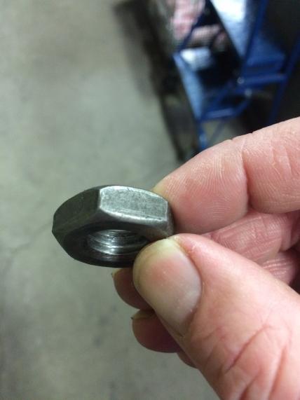
33 The above image shows how SAE Grade 8 hex head bolts can be identified. The above image shows how SAE Grade 8 hex nuts can be identified. The above image shows how SAE Grade 5 hex head bolts can be identified. The above image shows how SAE Grade 5 hex nuts can be identified. The above image shows how SAE Grade 2 hex head bolts can be identified. 23 of 29

34 The above image shows how SAE Grade 2 hex nuts can be identified. 24 of 29


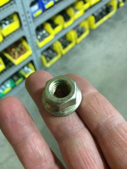
35 The above images show different types of zinc electroplated fasteners. 25 of 29


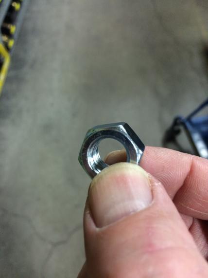
36 The above images show different types of clean non-plated fasteners. 26 of 29


37 Zinc electroplated Stainless The bolt on the left is zinc electroplated. The bolt on the right is stainless steel. The above image is a brass machine screw and brass hex nut. 27 of 29


38 All alloy steel socket head cap screws are have an 180,000 psi tensile strength for ½ and smaller bolts and 170,000 psi tensile strength for 5/8 and larger bolts. Use the SAE Grade 8 recommended tightening torque tables for socket head cap screws. All alloy steel socket flat countersunk head cap screws have a 150,000 psi minimum tensile strength. Use the SAE Grade 8 recommended tightening torque tables for alloy steel socket flat countersunk head cap screws. 28 of 29


39 All alloy steel socket button head cap screws have a 137,000 psi minimum tensile strength. Use the SAE Grade 5 recommended tightening torque tables for alloy steel socket button head cap screws.. Alloy Steel Stainless The fasteners on the left are alloy steel socket set screws. The fasteners on the right are stainless socket set screws. If further information is needed, call Darley at Chippewa Falls, WI or of 29
W.S. DARLEY & CO. REPAIR SERVICE INSTRUCTIONS TYPE 2 1/2 AGE PORTABLE PUMP PUMP DISASSEMBLY FOR OVERHAUL Refer to Drawing DAC0600
 W.S. DARLEY & CO. REPAIR SERVICE INSTRUCTIONS TYPE 2 1/2 AGE PORTABLE PUMP PUMP DISASSEMBLY FOR OVERHAUL Refer to Drawing DAC0600 1. Remove discharge (73) from pump casing (4). Discard gasket or o ring
W.S. DARLEY & CO. REPAIR SERVICE INSTRUCTIONS TYPE 1 1/2 AGE PORTABLE PUMP. PUMP DISASSEMBLY FOR OVERHAUL Refer to Drawing DAC0101/DAC0506
 W.S. DARLEY & CO. REPAIR SERVICE INSTRUCTIONS TYPE 1 1/2 AGE PORTABLE PUMP PUMP DISASSEMBLY FOR OVERHAUL Refer to Drawing DAC0101/DAC0506 1. Remove discharge (48) from pump casing (40). Discard gasket/quad
1984 Dodge W250 PICKUP
 1984 Dodge W250 PICKUP Submodel: Engine Type: V8 Liters: 5.2 Fuel Delivery: CARB Fuel: GAS Dana 44 MODELS THROUGH 1984 2. Raise and safely support the vehicle, then remove the wheel hub and bearings as
CP-1, CP-2, CP-2L & CPD-2 Series Overhaul
 Replacement of Mechanical Seals for CM, CMU, CS and CSU Series Pumps Installation Instructions Form No. F-1031 Section 5013 Issue Date 03/01/85 Rev. Date 02/08/11 CP-1, CP-2, CP-2L & CPD-2 Series Overhaul
TC20 Chain Driven Power Take-Off Overhaul Instructions
 TC20 Chain Driven Power Take-Off Overhaul Instructions Table of Contents Section Page Introduction 4 Ordering Repair Parts 4 General Information 5 Special Tools 6 Disassembly See Page 2 Reassembly See
Mustang Differential Gears - Installation Instructions
 Mustang Differential Gears - Installation Instructions The below installation instructions work for the following products: Ford Racing Gears - 3.73 Gears for 8.8" Ford Rear End Ford Racing Gears - FRPP
1988 Chevrolet Pickup V SUSPENSION - FRONT (4WD)' 'Front Suspension - "V" Series 1988 SUSPENSION - FRONT (4WD) Front Suspension - "V" Series
' 'Front Suspension - V Series 1988 SUSPENSION - FRONT (4WD) Front Suspension - V Series") 1988 SUSPENSION - FRONT (4WD) Front Suspension - "V" Series DESCRIPTION NOTE: Vehicle serial numbers used in this article has been abbreviated for common reference to Chevrolet and GMC models. Chevrolet
1988 SUSPENSION - FRONT (4WD) Front Suspension - "V" Series DESCRIPTION NOTE: Vehicle serial numbers used in this article has been abbreviated for common reference to Chevrolet and GMC models. Chevrolet
4.2 WATER PUMP (GEAR CASE MOUNTED AND LATER) (GCM)
 (GCM)") SERIES 60 SERVICE MANUAL 4.2 WATER PUMP (GEAR CASE MOUNTED - 1991 AND LATER) (GCM) The centrifugal-type water pump circulates the engine coolant through the cooling system. The pump is mounted on the rear
SERIES 60 SERVICE MANUAL 4.2 WATER PUMP (GEAR CASE MOUNTED - 1991 AND LATER) (GCM) The centrifugal-type water pump circulates the engine coolant through the cooling system. The pump is mounted on the rear
TL (TIL03029) REPAIR MANUAL. Telma model FN72-40 replacement on Arvin Meritor forward tandem carrier. Page 1 of JUL-11.
 REPAIR MANUAL. Telma model FN72-40 replacement on Arvin Meritor forward tandem carrier. Page 1 of JUL-11.") REPAIR MANUAL Telma model FN72-40 replacement on Arvin Meritor forward tandem carrier Page 1 of 10 29-JUL-11 Exploded view P/N: FE962100 Stator Carrier Kit Includes: Qty Description Telma P/N 1 Stator
REPAIR MANUAL Telma model FN72-40 replacement on Arvin Meritor forward tandem carrier Page 1 of 10 29-JUL-11 Exploded view P/N: FE962100 Stator Carrier Kit Includes: Qty Description Telma P/N 1 Stator
Next, chase the threads in the lower A-arm mounts with the 5/8-18 tap and blowout any remaining particles.
 Next, chase the threads in the lower A-arm mounts with the 5/8-18 tap and blowout any remaining particles. Now, apply some anti-seize to the threads of the pivot stud. Also put anti-seize inside the bore
2002 F-Super Duty /Excursion Workshop Manual
 Page 1 of 25 SECTION 307-01: Automatic Transaxle/Transmission 2002 F-Super Duty 250-550/Excursion Workshop Manual ASSEMBLY Procedure revision date: 05/23/2001 Transmission Special Tool(s) Remover, O-Ring
STEPS Install the (A) input shaft with long spliced end first. Install the (B) aligning pin.
 input shaft with long spliced end first. Install the (B) aligning pin.") 1999 Ford Truck Econoline E450 Super Duty V10-6.8L VIN S Vehicle > Transmission and Drivetrain > Automatic Transmission/Transaxle > Service and Repair > Overhaul > 4R100 > Assembly STEPS 51-94 51. Install
1999 Ford Truck Econoline E450 Super Duty V10-6.8L VIN S Vehicle > Transmission and Drivetrain > Automatic Transmission/Transaxle > Service and Repair > Overhaul > 4R100 > Assembly STEPS 51-94 51. Install
Overhaul Instructions. S100 Series Centrifugal Fire Pumps. Table of Contents F /22/02 1/19/18
 S100 Series Centrifugal Fire Pumps Overhaul Instructions Form No. F-1031 Section 4219 Issue Date 02/22/02 Rev. Date 1/19/18 Table of Contents Section Page Introduction 4 Ordering Repair Parts 4 Pump Models
DYNATRAC V6.0. WARNING: Only perform this installation if you are experienced, fully equipped mechanic.
 DYNATRAC V6.0 1999-2004 Ford Super Duty 250/550-4x4, Front Axle, Free Spin Conversion Kit Some of the less common tools, which will be required: 6 point Spanner socket (OTC #7090-A or equivalent) OR 4
KC Transmission Overhaul
 KC Transmissions Overhaul Instructions Form No. F-1031 Section 4310 Issue Date Rev. Date 02/08/96 12/30/15 Table of Contents Disassembling.............................. 1 Driven Shaft.................................
Wheel Bearing Replacement Passat TDI
 Rear Bearing/hub assembly replacement This is a fairly straight forward process. Pictures are not necessary for most of this procedure for a person with skills to do this repair. Anyone who thinks they
STERNDRIVE UNIT 3 B GEAR HOUSINGS MR/ALPHA ONE/ALPHA ONE SS
 STERNDRIVE UNIT 3 B 23146 GEAR HOUSINGS MR/ALPHA ONE/ALPHA ONE SS Table of Contents Page Identification........................... 3B-1 Specifications.......................... 3B-1 Torque Specifications................
Maintenance Information
 16573370 Edition 2 February 2014 Air Grinder 99V Series Maintenance Information Save These Instructions Product Safety Information WARNING Failure to observe the following warnings, and to avoid these
Installation & Maintenance Manual SPRING ENGAGED FRICTION CLUTCHES THROUGH SHAFT MOUNT - BALL BEARING PILOT REGULAR DUTY
 Installation & Maintenance Manual SPRING ENGAGED FRICTION CLUTCHES THROUGH SHAFT MOUNT - BALL BEARING PILOT REGULAR DUTY Catalog Products: E3A2R-STH E4A2R-STH E5A2R-STH E6A2G-STH And non-catalog variations
AXLE BEAM REPLACEMENT SERVICE KITS
 When sending out replacement axle beams, you must be sure to send the correct service kit for the beam size. Use the chart below to determine which service kit goes with which beam size. Illustrations
HIGH PRESSURE CONTROL VALVE PISTON BALANCED
 PISTON BALANCED All Rights Reserved. All contents of this publication including illustrations are believed to be reliable. And while efforts have been made to ensure their accuracy, they are not to be
Sport Model with an easy-lube spindle
 1. List of tools: Back To Top 1. Safety glasses 2. Hammer 3. Brass or aluminum punch 4. channel locks 5. Block of wood or plastic 6. grease gun 7. razor knife 8. 6" long, 2" diameter or 1 ½" diameter pipe
TECHNICAL BULLETIN. Yoke Removal and Installation Procedure for Meritor Drive Axles. Remove the Yoke and Pinion Seal WARNING CAUTION CAUTION.
 Issued 11-99 TECHNICAL BULLETIN Yoke Removal and Installation Procedure for Meritor Drive Axles Remove the Yoke and Pinion Seal Figure 1 WARNING Park the vehicle on a level surface. Block the wheels to
Drive/Motor Disassembly: Assembly Instructions - Quick-Change Pencil Grinder. Header 1. xxxxxx
 Disassembly/Assembly Instructions - Quick-Change Pencil Grinder, Drive & Motor Models: 60051, 60052 Important: Use these instructions along with tool parts page or manual. Notice: Shut off air supply.
FRONT DRIVELINE MODIFICATION MAY BE NECESSARY!!!!
 INSTALLATION INSTRUCTIONS FOR 2009 DODGE 2500/3500 4WD & 1500 Mega Cab 6 SUSPENSION SYSTEM PART NUMBER 7206 Requires the following parts (sold separately) for a complete installation: Front Coil Spring
Maintenance Information
 16573347 Edition 2 February 2014 Air Grinder Series 88H Maintenance Information Save These Instructions Product Safety Information WARNING Failure to observe the following warnings, and to avoid these
Maintenance Information
 16573321 Edition 3 February 2014 Air Grinder Series 61H Maintenance Information Save These Instructions Product Safety Information WARNING Failure to observe the following warnings, and to avoid these
Complete Disassembly of Pump. Replacement of Packing or Mechanical Seals Without Disassembling the Pump
 CS/CSU Series Fire Pumps Overhaul Instructions Form No. F-1031 Section 4211 Issue Date 06/30/95 Rev. Date 12/13/17 Table of Contents Type of Overhaul Complete Disassembly of Pump Replacement of Packing
12 L * OH**
 Parts Manual Ersatzteil--Liste 12L27.. series 0.9 hp ERGO Short Coupled Low Profile Grinders & Sanders 45--8175 TOOL CLASSIFICATION 12 = ERGO Grinder/Sander 12 L 2 7 12 27 08* OH** -- TYPICAL MODEL THROTTLE
Tugger T-Bolts Coupling (Extension) Nuts Eye Bolts Metric Coupling (Ext.) Nuts Latch Swing Bolts Heavy Hex Nuts...
 Nuts Eye Bolts Metric Coupling (Ext.) Nuts Latch Swing Bolts Heavy Hex Nuts...") INDEX Threaded Rod... 4 T-Slot Nuts... 14 Driver Studs - Stainless Steel... 4 Stainless Steel T-Nuts... 14 Driver Studs... 4-5 Stainless Steel Flange Nuts... 15 Driver Studs Various Thread Lengths... 6
INDEX Threaded Rod... 4 T-Slot Nuts... 14 Driver Studs - Stainless Steel... 4 Stainless Steel T-Nuts... 14 Driver Studs... 4-5 Stainless Steel Flange Nuts... 15 Driver Studs Various Thread Lengths... 6
Instruction Manual for HSPA Take-Up Units
 Installation Instruction Manual for HSPA Take-Up Units Warning: To ensure the drive is not unexpectedly started, turn off and lockout the power source before proceeding. Failure to observe these precautions
3M Overhaul Service Kit
 SERVICE INSTRUCTIONS FOR 3M 12,000 RPM 5 in. (127 mm) and 6 in. (150 mm) RANDOM ORBITAL SANDERS 3M Overhaul Service Kit The part number 20347, 3M Overhaul Service Kit, contains all the replacement parts
LIMITED SLIP DIFFERENTIAL INSTALLATION
 Installation of the limited slip gear can be done with axle out of car or with car lifted to gain access from underneath. Refer to repair manual for proper lifting instructions if car is to be lifted.
Introduction. Pressed Shaft Flowmeter. Flowmeter Service Kits. Disassembly. Idler Shaft Removal
 Flowmeter Service Kits Introduction See Figure. This instruction sheet provides repair procedures for flowmeters that use either pressed or screw-in shafts. Refer to the applicable repair procedure: Pressed
3M Overhaul Service Kit
 SERVICE INSTRUCTIONS FOR 3M 12,000 RPM 3 in. (77 mm) RANDOM ORBITAL SANDERS 3M Overhaul Service Kit The part number 20346, 3M Overhaul Service Kit, contains all the replacement parts that naturally wear
ASSEMBLY INSTRUCTIONS
 ASSEMBLY INSTRUCTIONS FOR FORGED SUPERLITE BIG BRAKE FRONT HUB KIT WITH 3.00 DIAMETER VENTED ROTOR 968-969 FORD MUSTANG (DISC BRAKE SPINDLE ONLY) PART NUMBER GROUP 0-950 WARNING INSTALLATION OF THIS KIT
Falk Speed Reducers Right Angle/Vertical Drives Disassembly & Assembly
 Falk Speed Reducers Right Angle/Vertical Drives Disassembly & Assembly Type AFX Sizes 27 thru 88 (Page 1 of 10) HOW TO USE THIS MANUAL This manual provides detailed instructions on disassembly and assembly
Disassembly Instructions hp. Dynafile II Models: 40352, 40353
 Disassembly Instructions - 0.4 hp. Dynafile II Models: 40352, 40353 Important: Use these instructions along with the tool parts page or manual. Notice: Shut off the air supply and depress throttle lever
Part # Chevy Level 2 Air Suspension Package One Piece Frame
 350 S. St. Charles St. Jasper, In. 47546 Ph. 812.482.2932 Fax 812.634.6632 www.ridetech.com Part # 11020299 55-57 Chevy Level 2 Air Suspension Package One Piece Frame Front Components: 1 11013001 Master
FRONT DRIVELINE MODIFICATION MAY BE NECESSARY!!!!
 INSTALLATION INSTRUCTIONS FOR 2009 DODGE 2500/3500 4WD & 1500 Mega Cab 6 SUSPENSION SYSTEM PART NUMBER 7206 Requires the following parts (sold separately) for a complete installation: Front Coil Spring
Gearbox Servicing
 Safety Precautions : Be certain to clamp or securely support the gearbox and sub-assemblies to prevent injuries to hands and feet due to inadvertent dropping or falling over. Always wear safety glasses
HIGH FLOW COLD AIR INTAKE SYSTEM INSTALLATION INSTRUCTIONS D , D A
 HIGH FLOW COLD AIR INTAKE SYSTEM INSTALLATION INSTRUCTIONS D760-0320, D760-0320A 1992-95 325i, is 1995 M3 (3.0L) Parts List: 1 Intake Tube 1 Silicone Hose 1 Air Flow Meter Bracket 1 Hose Clamp (#36z) 1
HYDRAULICS. TX420 & & lower. Hydraulic Tandem Pump Removal. 4. Remove the LH side panel (Fig. 0388).
.") TX420 & 425 240000299 & lower 4. Remove the LH side panel (Fig. 0388). Hydraulic Tandem Pump Removal Note: Cleanliness is a key factor in a successful repair of any hydraulic system. Thoroughly clean all
TX420 & 425 240000299 & lower 4. Remove the LH side panel (Fig. 0388). Hydraulic Tandem Pump Removal Note: Cleanliness is a key factor in a successful repair of any hydraulic system. Thoroughly clean all
SPECIAL TOOLS Dodge Pickup 5.9L Eng R3500. Fig 1: Identifying Remover C-3985-B (Special Tool) 9/6/13 Printer Friendly View
 9/6/13 Printer Friendly View") Procedures 2003 Dodge Pickup 5.9L Eng R3500 manual transmission SPECIAL TOOLS Fig 1: Identifying Remover C-3985-B (Special Tool) www2.prodemand.com/print/index?content=tabs&module=true&tab=true&terms=true&ymms=false&classname=
Procedures 2003 Dodge Pickup 5.9L Eng R3500 manual transmission SPECIAL TOOLS Fig 1: Identifying Remover C-3985-B (Special Tool) www2.prodemand.com/print/index?content=tabs&module=true&tab=true&terms=true&ymms=false&classname=
DRIVE AXLE Nissan 240SX DESCRIPTION & OPERATION AXLE RATIO & IDENTIFICATION AXLE SHAFT & BEARING R & I DRIVE SHAFT R & I
 DRIVE AXLE 1990 Nissan 240SX 1990 DRIVE AXLES Rear Axle - R200 240SX, 300ZX DESCRIPTION & OPERATION The axle assembly is a hypoid type gear with integral carrier housing. The pinion bearing preload adjustment
ASSEMBLY INSTRUCTIONS FOR SUPERLITE 6 BIG BRAKE FRONT CHALLENGE SERIES BRAKE KIT WITH HUB AND DIAMETER VENTED ROTOR
 ASSEMBLY INSTRUCTIONS FOR SUPERLITE BIG BRAKE FRONT CHALLENGE SERIES BRAKE KIT WITH HUB AND 1.88 DIAMETER VENTED ROTOR 197-199 CAMARO, DISC/DRUM SPINDLE 197-1974 NOVA, DISC/DRUM SPINDLE 194-19 CHEVY II,
Kysor On/Off Rear Air Fan Drive
 . Proper precautions must be taken to prevent personal injury from contact with moving parts, unintended engine start or other hazards present when working with powered equipment. Refer to the vehicle
REMOVAL & INSTALLATION
 REMOVAL & INSTALLATION Removal 1. Center steering wheel. Disconnect negative battery cable. Remove steering coupling shield (if equipped). Disconnect steering shaft at flexible coupling or pot joint. Note
Amarillo PUMP DRIVES (250 HP THROUGH 350 HP) INSTRUCTIONS FOR REPAIRING MODELS 250, 300, and 350
 INSTRUCTIONS FOR REPAIRING MODELS 250, 300, and 350") Amarillo PUMP DRIVES (250 HP THROUGH 350 HP) INSTRUCTIONS FOR REPAIRING MODELS 250, 300, and 350 Amarillo Right Angle Pump Drives, if properly installed and maintained, should provide years of service
Amarillo PUMP DRIVES (250 HP THROUGH 350 HP) INSTRUCTIONS FOR REPAIRING MODELS 250, 300, and 350 Amarillo Right Angle Pump Drives, if properly installed and maintained, should provide years of service
Hydraulic Motors Repair Instructions
 Hydraulic Motors Repair Instructions Motors for Global External Hydraulic Vibrators Models 2HC - pn #251020 5HC - pn #251050 Global Manufacturing, Inc. 101 E 22nd St Little Rock, Arkansas 2206 V I B R
INSTALLATION INSTRUCTIONS Progress Technology Rear Anti-Sway Bar Honda Civic Part # No Revision (7/20/16)
") INSTALLATION INSTRUCTIONS Progress Technology Rear Anti-Sway Bar Honda Civic 96-00 Part # 62.1042 No Revision (7/20/16) WHO SHOULD INSTALL THIS PRODUCT? Progress Technology products should only be installed
INSTALLATION INSTRUCTIONS Progress Technology Rear Anti-Sway Bar Honda Civic 96-00 Part # 62.1042 No Revision (7/20/16) WHO SHOULD INSTALL THIS PRODUCT? Progress Technology products should only be installed
SB 160 QUICK REPAIR GUIDE FOR HALE THERMAL RELIEF VALVE TRV 120, TRV 170, TRV L
 Use this guide and PL729 to repair a Hale Thermal Relief Valve (TRV) when the valve does NOT vent above or does vent below 120 F (or 170 F for a TRV 170) or fails to provide the appropriate status indication
RS-2 SINGLE ACTION REAR BUMPER WITH TIRE CARRIER INSTALL MANUAL FOR JEEP WRANGLER ALL MODELS.
 RS-2 SINGLE ACTION REAR BUMPER WITH TIRE CARRIER INSTALL MANUAL FOR 2007-2016 JEEP WRANGLER ALL MODELS. Rear Bumper Installation Instructions 1) Remove factory rear bumper, (this includes all tow hitch
250P Manure Spreader
 0P Manure Spreader Illustrated Parts Breakdown Page - Page Page Page Page Page Page Page Page Page Page Page Page Page Page - Page Page Page 0 Complete Front End PTO/Jack/Hitch Assembly Front Pulley Assembly
Constant Velocity Joint: Service and Repair Wheel Drive Shaft Outer Joint and Boot Replacement REMOVAL PROCEDURE
 Constant Velocity Joint: Service and Repair Wheel Drive Shaft Outer Joint and Boot Replacement REMOVAL PROCEDURE Tools Required - J 8059 Snap Ring Pliers - J 35910 Seal Clamp Tool - J 41048 Small Swage
'88-'00 CHEVROLET/GMC IFS 4WD(8LUG) OLD BODY STYLE 6" SUSPENSION SYSTEM P/N
 OLD BODY STYLE 6 SUSPENSION SYSTEM P/N") 4/10/13 '88-'00 CHEVROLET/GMC IFS 4WD(8LUG) OLD BODY STYLE 6" SUSPENSION SYSTEM P/N. 10-41888 INSTALLATION INSTRUCTIONS APPLICATION WARNING: Applicable for hub mounted ABS sensor models only. Not for 1992-94
4/10/13 '88-'00 CHEVROLET/GMC IFS 4WD(8LUG) OLD BODY STYLE 6" SUSPENSION SYSTEM P/N. 10-41888 INSTALLATION INSTRUCTIONS APPLICATION WARNING: Applicable for hub mounted ABS sensor models only. Not for 1992-94
Installation Notes: #86000-R Race Series +3.5 L/T Kit
 159 North Maple St. Unit J, CORONA CA 92880 P. 951-737-9682 F. 951-737-9006 WWW.CHAOSFAB.COM Installation Notes: #86000-R Race Series +3.5 L/T Kit Factory manual is recommended for removal and re-installation
FULL FLOATER HUB KIT INSTRUCTION MANUAL
 FULL FLOATER HUB KIT INSTRUCTION MANUAL WARNING: All components are shipped assembled for illustration purposes only. IT IS YOUR RESPONSIBILITY FOR FINAL ASSEMBLY. Please read instructions thoroughly before
Transmission Overhaul Procedures-Bench Service
 How to Assemble the Lower Reverse Idler Gear Assembly Special Instructions In 1996 Eaton changed the reverse idler system design. In the nut design, the reverse idler bearing was lubricated through a hole
Input Cage Leak Repair
 Revised 10-12 Input Cage Leak Repair Technical Bulletin Meritor Forward Tandem Drive Axles RP 140 and 160 Series (With a Pump) MD and RD 140 and 160 Series (Without a Pump) Revised 1 Technical 10-12 Bulletin
4410 TwinHydrostatic Gas Seal
 IS0 9001 CERTIFIED CHESTERTON FLUID SEALING DIVISION INSTALLATION INSTRUCTIONS 4410 TwinHydrostatic Gas Seal SEAL INSTALLATION Preparation Determine if the pump is in good condition. A. Check the shaft
Service Manual. Climate Control Inc.
 SECTION 2 Service - Clutch Servicing (Removal & Installation) - Shaft Seal Servicing (Removal & Installation) - Head & Valve Plate Servicing (Removal & Installation) - Baseplate Servicing (Removal & Installation)
354 CHAPTER EIGHT WATER PUMP
 354 CHAPTER EIGHT 33 Shift handle F : Forward N : Neutral R : Reverse proper alignment of the water tube to the water pump opening during each installation attempt. Make sure the locating pins enter the
First, check and record the camber and caster readings, they will be adjusted later.
 First, check and record the camber and caster readings, they will be adjusted later. The caliper-mounting bosses are machined perpendicular to the spindle so they are an excellent place for the level.
Tidland Great Expansion Leaf Shaft
 TIDLAND WINDING SOLUTIONS Tidland Great Expansion Leaf Shaft Installation, Operation and Maintenance EN MI 27L536158 1 L 6" and 12" Shaft Diameter with instructions for Add-on Leaf Assemblies IMPORTANT
DISC BRAKES SHOULD ONLY BE INSTALLED BY SOMEONE EXPERIENCED AND COMPETENT IN THE INSTALLATION AND MAINTENANCE OF DISC BRAKES READ ALL WARNINGS
 ASSEMBLY INSTRUCTIONS FOR SUPERLITE BIG BRAKE FRONT HUB KIT WITH 1.90 DIAMETER VENTED ROTOR 197-199 CAMARO, DISC/DRUM SPINDLE 197-197 NOVA, DISC/DRUM SPINDLE 19-19 CHEVY II, DRUM SPINDLE WITH MODIFICATIONS
Maintenance Information
 45528270 Edition 1 June 2007 Barring Motor T480 Series Maintenance Information Save These Instructions WARNING Always wear eye protection when operating or performing maintenance on this Barring Motor.
TIDLAND WINDING SOLUTIONS. Tidland Leaf Shaft. User Manual. Series 650/650HD/750 MI 27L L
 TIDLAND WINDING SOLUTIONS Tidland Leaf Shaft User Manual EN Series 650/650HD/750 MI 27L691995 1 L IMPORTANT SAFETY INSTRUCTIONS When using this Tidland product, basic safety precautions should always be
225 CARTRIDGE DUAL SEAL
 225 CARTRIDGE DUAL SEAL MECHANICAL SEAL INSTALLATION INSTRUCTIONS PREPARATION 1 2 500.010" 0,25 mm 3 4.32 µ" 0,8 µm R a 1000 + ±.001".002" 0,025mm 0,050mm CAUTIONS These instructions are general in nature.
FOR FUTURE REFERENCE SERIES 93HPS
 Hypro Series 93HPS Hydraulically Driven Wetseal Multistage Pumps Repair Manual KEEP FOR FUTURE REFERENCE Form L-1578R Rev. A SERIES 93HPS Hydraulically Driven Stainless Steel Multistage Centrifugal Pumps
Assembly Manual. 1/10th Formula 1 Car
 Assembly Manual 1/10th Formula 1 Car Center Pivot Bag 1 3374 - Center Pivot Socket 40194 - Hard Anodized Alum Pivot ball 3254-2-56 *Note - Sometimes it is helpful to slightly over-tighten the top clamp
InstalL Instructions. trail-creeper 4.70 transfer case gear kit ( KIT and KIT) kit contents
 kit contents") InstalL Instructions trail-creeper 4.70 transfer case gear kit (105000-1-KIT and 105001-1-KIT) kit contents 5356 PINE AVE FRESNO, CA 93727 USA TOLL FREE: 877.4X4.TOYS WORLDWIDE: 559.252.4950 WWW.TRAIL-GEAR.COM
InstalL Instructions trail-creeper 4.70 transfer case gear kit (105000-1-KIT and 105001-1-KIT) kit contents 5356 PINE AVE FRESNO, CA 93727 USA TOLL FREE: 877.4X4.TOYS WORLDWIDE: 559.252.4950 WWW.TRAIL-GEAR.COM
Char-Lynn Hydraulic Motor. Repair Information Series. April, 1997
 Char-Lynn Hydraulic Motor April, 1997 Repair Information Geroler Motors 002 00 004 Parts Drawing 1 See Note 2 Page 1 22 1 9 1-1/4 Split Flange Ports 8 7 6 5 B 1 See Note 2 Page 2 24 4 14 19 20 15 1 18
63-82 CORVETTE IMPALA KIT INSTRUCTIONS
 63-82 CORVETTE 61-69 IMPALA KIT INSTRUCTIONS RACE, STREET, 2 PISTON AND 4 PISTON FRONT KITS ARE ALL COVERED IN THESE INSTRUCTIONAL SHEETS. 1 AEROSPACE COMPONENTS 727.347.9915 Preparing the spindle: You
ATLAS TRANSFER CASES CABLE SHIFTER units built after 5/1/12
 KIT CONSISTS OF: No. Qty Part No. Description P.O. Box 247, 4320 Aerotech Center Way PAGE 1 OF 6 Page Rev. Date: 08-01-17 1 1 302051 BASE- TWIN STICK MOUNT 2 1 302060 BOOT- TWIN STICK 3 1 302063 BOOT RING-
Kysor On/Off Rear Air Fan Drive
 . Proper precautions must be taken to prevent personal injury from contact with moving parts, unintended engine start, or other hazards present when working with powered equipment. Refer to the vehicle
NOTE: Visit our website at for video repair procedures, under the Tools section.
 Repair Instructions Hypro Repair Tools: Tool Box No. 3010-0168 1/4" Allen Wrench No. 3020-0008 Support Bars (2) No. 3010-0064 Port Brush No. 3010-0066 1/16" Allen Wrench No. 3020-0009 Brush Holder No.
Maintenance Information
 Form 16573321 Edition 1 July 2004 Air Grinder Series 61H Maintenance Information Save These Instructions Always wear eye protection when operating or performing maintenance on this tool. Always turn off
Passenger/Right Top Support Bracket. (2) 10mm Nut Plates
 10mm Nut Plates") PARTS LIST: 1 Extreme Grille Guard 16 12mm x 32mm OD x 3mm Flat Washers 1 Driver/Left Frame Mounting Bracket 10 12mm Lock Washers 1 Passenger/Right Frame Mounting Bracket 10 12mm Hex Nuts 1 Driver/Left
PARTS LIST: 1 Extreme Grille Guard 16 12mm x 32mm OD x 3mm Flat Washers 1 Driver/Left Frame Mounting Bracket 10 12mm Lock Washers 1 Passenger/Right Frame Mounting Bracket 10 12mm Hex Nuts 1 Driver/Left
'99-03 CHEVROLET/GMC IFS 4WD 6" SUSPENSION SYSTEM P/N INSTALLATION INSTRUCTIONS
 1/16/04 '99-03 CHEVROLET/GMC IFS 4WD 6" SUSPENSION SYSTEM P/N. 10-41099 INSTALLATION INSTRUCTIONS NOTE: Each Lift Kit and options to Lift Kits are packaged separately. Therefore, installation procedures
AUTO MO TIVE CORPORATION TC 142 PD TRANSFER CASE SERV ICE MAN UAL. Fabco Automotive Corporation,
 AUTO MO TIVE CORPORATION TC 142 PD TRANSFER CASE SERV ICE MAN UAL Fabco Automotive Corporation, TABLE OF CONTENTS SECTION TC-142 PD TRANSFER CASE SERVICE MANUAL Introduction Operation Specification LUBRICATION
Chevy Nova Pro-Touring Front Suspension Installation Instructions
 1962-1967 Chevy Nova Pro-Touring Front Suspension Installation Instructions 1-800-984-6259 www.totalcostinvolved.com 1 Pro-Touring Clip A-Arm Assembly Sway Bar Assembly Fender Panel Kit 8 7/16-20 * 1 ¼
114 NOSE SEIKO CO.,LTD NOSE SEIKO CO.,LTD
 114 NOSE SEIKO CO.,LTD NOSE SEIKO CO.,LTD 115 and Part Code Applicable axis diameter Feature Part Code 5 ~ 3 General purpose cam follower with screwdriver groove on the stud head. Available with stainless
INSTALLATION MANUAL
 364045-2 INSTALLATION MANUAL Parts List 1 Driver / left sidebar 1 Passenger / right sidebar 8 Sidebar brackets 10 Clip-on nuts, 8mm 16 Hex bolt, 8mm x 25mm 16 Flat washer, 8mm 16 Lock washer, 8mm 18 Hex
93-02 CAMARO BILLET HUB STYLE KIT
 93-02 CAMARO BILLET HUB STYLE KIT FOR ANY QUESTIONS, PLEASE CALL US @ (727-347-9915) M-TH 8:00A.M. 8:00P.M., FR 8:00A.M.-7:00P.M. EST CLOSED SATURDAYS AND SUNDAYS YOU WILL NEED TO MODIFY YOUR SPINDLE.
Section 13. Tail Rotor Drive. RotorWay International A600 TALON Construction Manual. Section 13. Page A
 RotorWay International Page A Tail Rotor Drive Procedures covered in this section: Install driveshafts and gearboxes; install drive belt and tensioner; fabricate and install tail rotor pitch actuator arms;
BLACKBIRD INSTALLATION SUPPLEMENT
 BLACKBIRD INSTALLATION SUPPLEMENT FOR 2008-105 FORD 6.4 LITER DIESEL F-SERIES VERSION 3/10 Parts Blackbird Wiring Manual Installation Supplement 6.4 liter Diesel Owner s Manual Includes Warrantee Registration
SECTION Front Drive Axle/Differential
 205-03-i Front Drive Axle/Differential 205-03-i SECTION 205-03 Front Drive Axle/Differential CONTENTS PAGE Axle... 205-03-2 205-03-2 Front Drive Axle/Differential 205-03-2 Axle Special Tool(s) C-Frame
INTEGRAL POWER STEERING GEAR FORD Applies to F-100 F-350 (4X2), F-150 F-250 (4X4) And Bronco
, F-150 F-250 (4X4) And Bronco") Rockcrawler Steering Shop Manual page1 The following is from the Ford 1978 Truck Shop Manual, Volume 1 Chassis. It is provided here as a courtesy to classic Ford owners who would like to perform their
Rockcrawler Steering Shop Manual page1 The following is from the Ford 1978 Truck Shop Manual, Volume 1 Chassis. It is provided here as a courtesy to classic Ford owners who would like to perform their
Maintenance Information
 80234313 Edition 1 June 2006 Air Grinder, Die Grinder, Sander and Belt Sander Series G1 (Angle) Maintenance Information Save These Instructions WARNING Always wear eye protection when operating or performing
3.2 DRIVE TORQUE HUB. Roll, Leak and Brake Testing SECTION 3 - CHASSIS & TURNTABLE. 3-2 JLG Lift
 3.2 DRIVE TORQUE HUB Roll, Leak and Brake Testing 10 LUG PATTERN Torque-Hub units should always be roll and leak tested before disassembly and after assembly to make sure that the unit's gears, bearings
Tools, Equipment and Supplies Needed:
 153-162 DISC BRAKE/DUAL MASTER CYLINDER CONVERSION Please take the time to read the enclosed instructions carefully. If you have any questions, call our Product Assistance personnel for clarifi cation.
255 Cartridge Dual Seal
 MECHANICAL SEAL INSTALLATION INSTRUCTIONS 255 Cartridge Dual Seal Installation Instructions SEAL INSTALLATION Preparation Determine if the pump is in good condition. A. Check the shaft or sleeve. 1. Remove
Bag 1. Bag 1. Center Pivot. Center Pivot
 8 00734 01901 5 Center Pivot Bag 1 3374 - Center Pivot Socket 4019 - Alum Pivot ball 3254-2-56 Button Head *Note - Sometimes it is helpful to slightly over-tighten the top clamp screws, then work the ball
Installation Instructions
 Installation Instructions Jeep TJ Long Arm Suspension System 1997-2002 JEEP TJ 4WD 6 1997-2002 JEEP TJ 4WD FTS24002 & BK / FTS24003 & BK / FTS44002 & BK PARTS LIST FTS24002BK Jeep TJ 6' Box Kit 1 FTS24003BK
Maintenance Information
 80234313 Edition 2 May 2014 Air Grinder, Die Grinder, Sander and Belt Sander Series G1 (Angle) Maintenance Information Save These Instructions Product Safety Information WARNING Failure to observe the
Part # Cougar CoilOver System
 Front Components: 1 12103510 HQ Series Front CoilOvers 1 12102899 Lower StrongArms 1 12103699 Upper StrongArms 1 12109100 Front MuscleBar w/ PosiLinks 350 S. St. Charles St. Jasper, In. 47546 Ph. 812.482.2932
Trailer Axle Beam Replacement SERVICE MANUAL
 Trailer Axle Beam Replacement SERVICE MANUAL September 20, 2017 Trailer Axle Beam Service Manual TABLE OF CONTENTS System Information 2 Safety Information 2 Required Resources 2 Hub Removal 3 Axle Beam
SERIES1 NOZZLE CYLINDER REPAIR PROCEDURES
 THE FOLLOWING REPAIR PROCEDURE ENCOMPASSES THESE PHD ML UNITS : - ML309435, ML310142, ML310153, ML310254, ML310295, ML310427, 1) Refer to individual ML exploded view for actual part numbers. 2) Not all
EVO-1085 JK DoubleD Long Arm Upgrade. EVO /37 JK DoubleD LongArm Kit
 EVO-1085 JK DoubleD Long Arm Upgrade EVO-1084-35/37 JK DoubleD LongArm Kit (EVO-1084 pictured above with Bilstein 5100 Shocks and optional EVO HD Swaybar Endlinks) NOTES: Cutting and grinding is required