GT SERIES WET PRIME PUMPS SERVICE MANUAL
|
|
|
- Brianne Lester
- 5 years ago
- Views:
Transcription

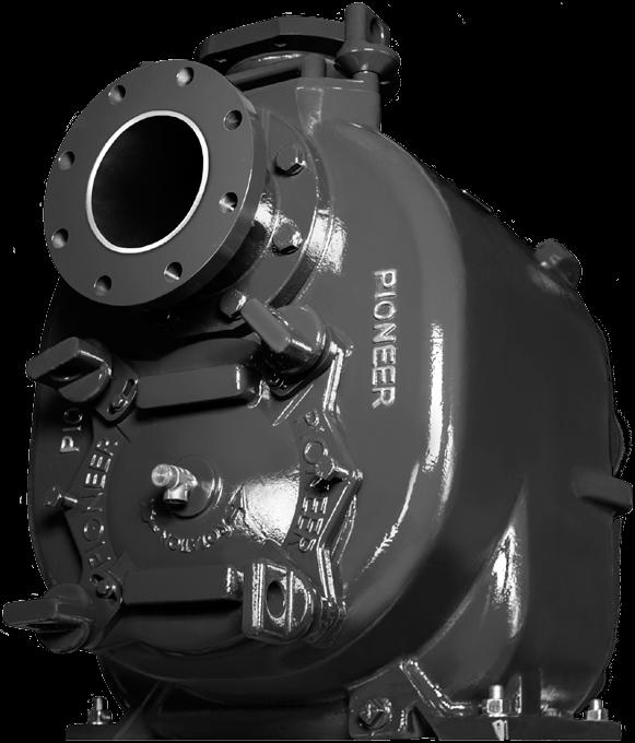


1 SERVICE MANUAL
2 BEFORE GETTING STARTED This manual is intended as a guide to disassembly and reassembly of a Pioneer Pump. It is to be used only by trained and experienced service technicians who are familiar with the correct selection and use of standard shop tools, equipment, and procedures. WARNING This manual provides installation, operation, and maintenance instructions for your Pioneer pump and is intended to make your personnel aware of any procedure that requires special attention because of potential hazards to personnel or equipment. Read all instructions carefully, and remember that pump installations are seldom identical. Centrifugal pumps are designed for specific service and may or may not be suited for any other service without loss of performance or potential damage to equipment or personnel. Therefore, this manual cannot possibly provide detailed instructions and precautions for each specific application. It is the responsibility of the owner/installer to ensure that applications not addressed in this manual are performed only after establishing that neither operator safety nor pump integrity are compromised by the installation. If there is ever any doubt about suitability for a specific purpose, contact Pioneer Pump, Inc. or your Pioneer Pump distributor for assistance. WARNING Before attempting to service or maintain your pump, read this manual carefully. Operator and maintenance personnel should have a good understanding of all aspects of the pump and pumping conditions. Failure of operating personnel to be familiar with all aspects of pump operation outlined in this manual could contribute to equipment damage, bodily injury or possible death. WARNING When servicing your Pioneer pump, be sure to use only genuine Pioneer Pump parts. These parts are designed to give you the longest wear life and performance that the pump was designed to achieve. Pioneer Pump has your safety in mind when designing the parts. If you choose to use other brands of parts in your Pioneer pump, operating safety could be compromised and the pump warranty will be void. WARNING The GT Series pumps are designed to handle mild industrial corrosives, residues, and light slurries containing large solids. Do not attempt to pump volatile, corrosive, or flammable materials that may damage the pump or endanger personnel as a result of pump failure. If the pump is used to handle any hazardous materials that can cause illness, either directly or indirectly, take precaution by wearing appropriate Personal Protective Equipment (PPE) when working around the pump and use appropriate safety equipment.. WARNING Do not operate the pump against a closed discharge valve for long periods of time. If the pump is operated against a closed discharge valve, the liquid inside the pump will become heated, build steam pressure, and possibly cause the pump casing to rupture or explode. If the pump is overheated, do not remove plates, covers, gauges, pipe plugs, or fittings from the pump. Vapor pressure from within the pump can cause the removed parts to be ejected with great force. Allow the pump to cool before servicing. 1
3 TABLE OF CONTENTS Before Getting Started....1 Theory of Operation Inspection Cover Disassembly...4 Inspection Cover Removal...4 Wear Plate Removal...4 Inspection Cover Reassembly... 5 Wear Plate Inspection Wear Plate Adjustment... 5 Relief Valve Service....9 Inspection Cover Registers...9 Wear Plate Reassembly...9 Rotating Assembly Component Removal Impeller Removal...10 Mechanical Seal Removal...11 Seal Plate Removal Pump Shaft and Bearing Removal...11 Rotating Assembly Component Reinstallation Bearing Housing Preparation...12 Bearing Installation...12 Shaft Assembly Installation Bearing Cap Installation Seal Plate Installation Mechanical Seal and Impeller Installation...13 Rotating Assembly Installation Flapper Valve Service Volute Inspection Appendices...15 Notes


4 THEORY OF OPERATION The design of the self-priming pump incorporates a reservoir of water and a standard volute within the pump case. The case is connected to the volute by an opening known as the reprime port. The pump case is filled with water and the pump is started. Air from the suction leg is mixed with the water in the pump case. Because of its lower density, the air rises and escapes through the discharge port. The water is recirculated from the volute to the pump casing through the reprime port and the vacuum at the eye of the impeller is thus maintained until the pump has eliminated air from the suction leg, and the pump primes. To Sump Discharge Port Suction Port/ Flapper Valve Impeller Eye Pump Case Volute Impeller Rotation Select a clean, suitable location for any required maintenance or repair. All work must be performed by a qualified service technician. WARNING Appropriate safety clothing must be worn when servicing the pump. Reprime Port WARNING Pump components may be heavy. Be sure to use appropriate lifting equipment when handling heavy components. WARNING Internal pump components may be extremely sharp. Be sure to wear appropriate safety clothing to protect against cuts. WARNING Verify the following: The electric motor, or diesel engine driver, is shut down and electrical power is locked out. Ensure that any pump auto start features are disabled. If pump components are hot, allow them to adequately cool before doing any service on the pump. The pump may have been pumping hazardous liquids. Wear appropriate safety clothing to protect against liquid coming into contact with any part of your body. Drain the pump only when the pump and pumpage are cool. Suction and discharge valves are shut. General maintenance can be performed without removing the pump from the driver. The following instructions assume disassembly of the pump is required. 3

 Drain Plug Jack Screws 5/8\"- 11 UNC (if required) WARNING Take care")


5 INSPECTION COVER DISASSEMBLY Inspection Cover Removal Drain the pump by removing the drain plug. Replace the drain plug when the pump is completely drained. Remove the four casing screws. All other screws and hardware on the inspection cover may remain in place. Note that the inspection cover weighs more than 50 lbs (25 kg). Be sure to use accepted lifting methods and precautions for handling the inspection cover. Inspection Cover Handles Inspection Cover Inner/Outer Flanges Inspection Cover Casing Screw (4) Drain Plug Jack Screws 5/8"- 11 UNC (if required) WARNING Take care when removing or reinstalling the inspection cover not to pinch or cut the O-rings on the inner and outer flanges of the inspection cover. Firmly grip the inspection cover by the upper and lower inspection cover handles and pull outward while jiggling the cover. The inspection cover and wear plate assembly will come free from the pump casing. If the inspection cover does not pull out by hand, the inspection cover has two threaded jack screw holes that can be used with jack screws to force it free from the pump casing. The jack screw threads should be 5/8-11 UNC. Tighten the two jack screws evenly until the inspection cover is forced from the pump case. Wear Plate Removal With the inspection cover removed from the pump case, the wear plate can be removed by unscrewing the six 3/8-16 UNC capscrews holding the wear plate to the inspection cover. If the wear plate does not come off easily after removing the six capscrews, give the wear plate a light tap with a plastic mallet and the wear plate should fall free. Wear Plate Capscrew (6) 3/8"-16 UNC 4

, replace the wear plate. Clearance < 0.040\" (1.016 mm) Wear Plate Adjustment The pump wear plate is easily and externally adjusted.")

6 INSPECTION COVER REASSEMBLY Wear Plate Inspection The normal wear pattern for the wear plate to the impeller will show greater wear to the outside diameters of the impeller and wear plate. To check the wear clearance between the wear plate and the impeller, place the impeller on a workshop bench with the vanes facing up. Center the wear plate on top of the impeller, and using a feeler gauge, measure the clearance between the impeller vane and the wear plate. If the gap is greater than 0.040" (1.016 mm), replace the wear plate. Clearance < 0.040" (1.016 mm) Wear Plate Adjustment The pump wear plate is easily and externally adjusted. A worn wear plate, or one out of adjustment, will result in slow or no priming and reduced pump efficiency. To adjust the wear plate, refer to the diagram and follow the described procedure: 1. Remove the four casing screws, adjusting screw retainer capscrews, and adjusting screw retainers. Casing Screw Adjusting Screw Retainer Adjusting Screw Retainer Capscrew 5


7 INSPECTION COVER REASSEMBLY Wear Plate Adjustment (Cont.) 2. Loosen the four hollow adjusting screws by several turns. Hollow Adjusting Screws 3. Replace the two diagonally-opposite casing screws and tighten them evenly until the wear plate contacts the impeller. This can be accomplished by tightening the casing screws in small increments while turning the pump shaft by hand until contact is detected. Casing Screws 6


8 INSPECTION COVER REASSEMBLY Wear Plate Adjustment (Cont.) 4. Once contact is established, loosen the two casing screws by several turns. Back off the two casing screws by several turns 5. In small increments, tighten the two hollow adjusting screws under the retaining screws while turning the shaft by hand until rubbing is no longer detected. 6. Tighten the two casing screws by hand until they are just snug against the hollow adjusting screws. Tighten both hollow adjusting screws evenly Tighten both case screws until snug against the hollow adjusting screws 7


9 INSPECTION COVER REASSEMBLY Wear Plate Adjustment (Cont.) 7. Tighten the two opposite hollow adjusting screws until they just contact the pump case. Hollow Adjusting Screws Pump Case 8. Install the hollow adjusting screw retainers and retainer screws. Install the two remaining case screws and torque to specified value. Install two diagonally-opposite retainers, retainer screws, and case screws and tighten the case screws to the specified torque Remove these two case screws and reinstall the adjustment screw retainers and screws 8


10 INSPECTION COVER REASSEMBLY Wear Plate Adjustment (Cont.) 9. Remove the remaining two case screws, install the adjusting screw retainers and retainer screws, and torque the case screws to specified value. Install and torque the remaining two casing screws Relief Valve Service The relief valve is located at the center of the inspection cover. The relief valve should be replaced any time the pump overheats and the valve has been activated, or at each pump overhaul or major service. Inspection Cover When replacing the relief valve, always use a genuine Pioneer part. Apply a good quality thread sealant to the valve threads and install the relief valve into the inspection cover with the discharge spout pointing downward when the inspection cover is installed into the pump casing. Relief Valve Inspection Cover Registers Inspect the inspection cover registers (where the inspection cover contacts and seals the pump casing when installed) for any irregularities, burrs or damage. Wear Plate Reassembly Attach the wear plate to the inspection cover using six 3/8-16 UNC capscrews. Torque the capscrews to 35 ft-lbs (47 Nm). Install new O-rings to the inner and outer inspection cover flanges using a lubricant that is compatible with the material of the O-ring. 9

.")


11 ROTATING ASSEMBLY COMPONENT REMOVAL With the pump driver disconnected and clear of the work area, drain the oil from the seal reservoir and bearing housing. Remove the eight capscrews holding the rotating assembly to the pump casing and slide the rotating assembly straight back from the drive side of the pump casing. Note that each of the eight capscrew holes is threaded with 3/4-10 UNC threads that can be used with screws to force the rotating assembly from the pump housing. Place the rotating assembly on a clean surface for the remaining steps of disassembly. WARNING The rotating assembly can weigh up to 250 lbs (115 kg). Refer to the appendices section of this manual to determine the estimated weight of the rotating assembly for the pump model that you are servicing. Use suitable lifting equipment and techniques to handle the rotating assembly. Bearing Drain Seal Drain Impeller Removal Unscrew the impeller from the pump shaft by turning the impeller counter-clockwise while facing it. The impeller may be loosened by applying the impeller shaft tool to the pump drive shaft, making sure to engage the keyway on the shaft. The handle of the impeller shaft tool should be in contact with the work surface on the left side of the rotating assembly when facing the power input end of the rotating assembly. While wearing thick gloves and being careful of the sharp edges on the impeller, sharply turn the impeller counter-clockwise so that the handle of the impeller shaft tool impacts the work surface at the end of the rotation. Note that the procedure may have to be repeated a few times to loosen the impeller. WARNING Make certain that no personnel or obstructions are in the path of the impeller tool handle as it rotates. Impact with personnel or equipment could result in serious injury or death and damage to equipment. WARNING It is advised to wear hearing protection while performing this procedure as the impact of the handle with the work surface is very loud. WARNING The impeller weighs up to 43 lbs (20 kg). Please reference the appendices section of this manual for the weight of the impeller you are working with. Be sure to use appropriate lifting equipment and procedures. There may be impeller adjusting shims on the pump shaft at the back of the impeller. If shims are found, be sure to mark and store them safely for when the impeller is reassembled to the pump shaft. 10

.")


12 ROTATING ASSEMBLY COMPONENT REMOVAL Mechanical Seal Removal With the impeller removed, slide the mechanical seal assembly off the pump shaft. Each time the mechanical seal is removed, it should be replaced with a new genuine Pioneer mechanical seal. Seal Plate Removal Unscrew the seal plate capscrews and remove the seal plate. Remove the O-rings from the seal plate. The stationary seat is held in place by the compression of the O-ring so some effort may be required for removal. Pump Shaft and Bearing Removal WARNING The pump shaft and bearing assembly weighs up to 45 lbs (22 kg). Please refer to the appendices section of this manual to confirm the weight of the component you are working with. Be sure to use appropriate lifting equipment and procedure. Remove the bearing cap. There may be adjusting shims found between the bearing cap and the bearing housing. If shims are found, mark them, tag them, and store them for reassembly. Press the oil seals from the bearing cap and remove the O-ring. Using a plastic or rubber mallet, drive the pump shaft and bearings from the bearing housing by tapping on the impeller end of the pump shaft. To remove the bearings, pry up the locking tab on the bearing lockwasher and remove both the bearing nut and lockwasher. Both bearings can then be removed from the pump shaft, using a bearing puller. Bearing Housing O-ring Seal Plate Screw (4) 5/8"-11 UNC 2B x 1.50" Seal Plate Pry up the locking tab on the bearing lockwasher Seal Plate Outer O-ring Seal Plate Inner O-ring 11


13 ROTATING ASSEMBLY COMPONENT REINSTALLATION When reassembling the rotating assembly, it is always best to use genuine Pioneer parts from the parts diagram and list in this manual. The most convenient way to get the right parts is by using parts kits that are available from your Pioneer distributor. The parts included in the bearing housing kit and seal end kit are typically sufficient to rebuild the bearing housing component with new parts. Outer Drive- End Lip Seal Outer Pump- End Lip Seal Bearing Housing Preparation Inner Drive- Before installing the seal plate to the bearing housing, install the two oil seals in End Lip Seal the bearing housing shaft bore, paying particular attention to their orientation. Install the pump end bearing oil seal with the open side facing the bearings and flush with the back surface of the bearing housing bore. Install the run-dry oil seal with the open side facing the impeller and flush with the front surface of the bearing housing bore. Inner Pump- End Lip Seal Bearing Installation Before assembling the bearings on the pump shaft, be sure that the pump shaft has been thoroughly cleaned. Inspect the shaft for any nicks, burrs, scratches or other damage. Ensure that the shaft is not bent or distorted. Install new bearings. Do not reuse the bearings that were previously on the pump shaft. Using an electric oven, induction heater or hot plate, heat the bearings to a uniform temperature of approximately 250 F (120 C). Never heat the bearings with an open flame. After the bearings are sufficiently heated, they should be quickly installed on the shaft in one continuous motion to prevent the bearings from sticking on the shaft before they are fully seated against the shoulder of the shaft. After the bearings have been installed and allowed to cool, verify that they remain installed firmly against the shoulder of the pump shaft. If the bearings are not fully seated, use a press and suitable sleeve against the inner race to reposition to the proper position. Install the bearing washer and nut until firm, then rotate the nut clockwise to align the tab on the bearing washer with the notch on the nut. Bend a tab of the washer to lock the nut. Shaft Assembly Installation Thoroughly clean and inspect the bearing housing for any damage or irregularity. Slide the shaft and bearing assembly into the bearing housing until the outboard (power end) bearing seats against the shoulder in the housing. It may be necessary to press against the center of the shaft to seat it fully. Bearing Cap Installation Before installing the bearing cap, thoroughly clean and inspect it for any irregularities. Press new oil seals into the bearing cap so that they are just flush with their respective bores. Install a new bearing cap O-ring coated with clean engine oil. Using the adjusting shims that were previously set aside during disassembly, install the bearing cap to the bearing housing. Torque the capscrews to 165 ft-lbs (224 Nm). Using a dial indicator, adjust the pump shaft end play to be between 0.002" (0.05 mm) and 0.010" (0.25 mm). Shaft end play is adjusted by adding or removing shims between the bearing cap and bearing housing. O-ring Seal Plate 12
.")


14 ROTATING ASSEMBLY COMPONENT REINSTALLATION Seal Plate Installation Install the O-ring in the groove in the back face of the seal plate as shown in the illustration. Install the seal plate and evenly torque the seal plate capscrews to 63 ft-lbs (85 Nm). Mechanical Seal and Impeller Installation A new mechanical seal assembly should be installed any time the old mechanical seal is removed. Reusing the old mechanical seal will result in premature failure of the seal. It is advised to use a Pioneer cartridge mechanical seal. Be sure that the shaft and area into which the mechanical seal will be installed is perfectly clean. Lubricate the stationary seat bore in the seal plate with clean engine oil. In like manner, lubricate the mechanical seal sleeve O-ring and install it into the inside diameter of the mechanical seal sleeve. Do not use grease or silicone lubricants. Just before installing the seal, remove the split spacers from between the snapring on the sleeve and the mechanical seal stationary seat. Slide the seal assembly on the pump shaft with the stationary seat first. Move the seal assembly into the stationary seat bore making sure it is completely seated in the stationary seat bore (this may take some force). If shims were removed from the impeller during disassembly, they should be reinstalled on the pump shaft at this point. Using an anti-seize compound on the shaft threads, install the impeller by screwing it down until tight. Using a feeler gauge, measure the clearance between the back vanes of the impeller and seal plate. The measurement should be between 0.20" (0.51 mm) and 0.040" (1.00 mm). The clearance between the impeller and the seal plate is adjusted using shims. The shims are placed between the hub face of the impeller and the end of the shaft sleeve in the mechanical seal assembly. Add or remove shims to arrive at the specified clearance. Rotating Assembly Installation If the complete pump has been moved to a work area, it is easiest to install the rotating assembly suspended from a hoist with the case bore facing upward. There is a threaded bore in the drive end of the shaft that will accommodate a 5/8-11 UNC (GT6, GT4) or 1/2-13 UNC (GT3) eye bolt. Using clean engine oil, lightly lubricate and install the rotating assembly O-rings and case bores. While ensuring that the areas inside the volute that come in contact with the rotating assembly are clean and free from defect, carefully slide the rotating assembly into the pump casing, making sure not to cut or nick any of the O-rings on the rotating assembly. When the rotating assembly is in its correct position, reinstall the eight capscrews and torque them evenly to 165 ft-lbs (224 Nm). 13

15 FLAPPER VALVE SERVICE Removal Remove the two casing screws on the flapper access port cover. While taking care not to cut or nick the flapper cover O-ring, remove the flapper access port cover. Make certain that the vent port O-ring stays in its counterbore unless replacement is required. Remove the flapper retention pin, followed by the flapper valve, through the flapper port. The flapper valve cannot be disassembled. If replacement of the flapper valve is required, the associated hardware must also be replaced. Replacement Install a new flapper assembly and reinstall the flapper retention pin. By applying a small amount of grease to the flapper access port O-ring groove, the O-ring will be retained in the groove during assembly. Ensure that both the flapper valve access cover and vent port O-rings are seated properly in their groove or counterbore before reinstalling the flapper access port cover. Replace the flapper access port cover, being careful not to cut or nick the flapper cover O-ring. Install and hand-tighten the two casing screws. VOLUTE INSPECTION Inspect the inside of the volute, looking for excessive wear or damage to any part of the interior. Particular attention should be paid to checking the cutwater for wear and the reprime port to ensure it is not blocked in any way. Casing Screws Flapper Access Port Cover Flapper Cover O-ring Vent Port O-ring Flapper Valve Retention Pin Flapper Valve 14
16 APPENDICES Bolt Torque Chart SIZE UNC WRENCH 304 SS (MARKINGS VARY) GRADE 5 GRADE 8 FT-LBS (NM) 1/4 7/16 3 / 4 9 / / 18 5/16 1/2 7 / 9 19 / / 37 3/8 9/16 13 / / / 65 7/16 5/8 20 / / / 104 1/2 3/4 31 / / / 159 9/16 13/16 45 / / / 230 5/8 15/16 63 / / / 317 3/4 1-1/8 112 / / / 563 7/8 1-5/ / / / /2 270 / / / /4 1-7/8 540 / / / 2711 Lubricating Oil and Capacities The GT Series Pump uses Viscosity Grade ISO32 Turbine Oil in all compartments. COMPARTMENT GT3 GT4 GT6 Bearing Housing 0.75 qt / 0.70 l 0.75 qt / 0.70 l 1 qt / 0.95 l Seal Reservoir 1.5 qt / 1.4 l 2.75 qt / 2.6 l 3.7 qt / 3.5 l Grease The GT Series pumps use grease as a barrier and lubricant between the double lip seals at the drive end of the pump. Any automotive- or industrialduty bearing grease is sufficient. Technical Specifications and Dimensions COMMON TORQUE VALUES (FT-LBS / NM) PART GRADE 5 STEEL STAINLESS STEEL Wear Plate to Inspection Cover 34 / / 18 Inspection Cover to Pump Casing 165 / 224 N/A Bearing Cap to Bearing Housing 165 / 224 N/A Seal Plate to Bearing Housing 34 / / 18 Rotating Assembly to Pump Casing 165 / 224 N/A OPERATING CLEARANCES (IN / MM) PART CLEARANCE Pump Shaft End Play / / 0.25 Impeller to Seal Plate 0.20 / / 1.00 APPROXIMATE COMPONENT WEIGHTS (LBS / KG) PART GT 3 GT4 GT6 Bare Shaft Pump 545 / / / 442 Inspection Cover Assembly 51 / / / 45 Impeller 15 / 9 14 / 6 43 / 20 Rotating Assembly 150 / / / 123 Shaft and Bearing Assembly 20 / 9 36 / / 22 15
17 NOTES 16
18 NOTES 17
19 NOTES 18
20 FORM 2102 REV pioneerpump.com
DRIVE AXLE Nissan 240SX DESCRIPTION & OPERATION AXLE RATIO & IDENTIFICATION AXLE SHAFT & BEARING R & I DRIVE SHAFT R & I
 DRIVE AXLE 1990 Nissan 240SX 1990 DRIVE AXLES Rear Axle - R200 240SX, 300ZX DESCRIPTION & OPERATION The axle assembly is a hypoid type gear with integral carrier housing. The pinion bearing preload adjustment
DELTA O-RING CARTRIDGE SEAL ASSEMBLY AND INSTALLATION INSTRUCTIONS INTRODUCTION:
 DELTA O-RING CARTRIDGE SEAL ASSEMBLY AND INSTALLATION INSTRUCTIONS INTRODUCTION: These instructions are provided to familiarize the user with the seal and its use. The instructions must be read carefully
DELTA O-RING CARTRIDGE SEAL ASSEMBLY AND INSTALLATION INSTRUCTIONS INTRODUCTION:
 DELTA O-RING CARTRIDGE SEAL ASSEMBLY AND INSTALLATION INSTRUCTIONS INTRODUCTION: These instructions are provided to familiarize the user with the seal and its use. The instructions must be read carefully
Maintenance Instructions
 General Note These instructions contain information common to more than one model of Bevel Gear Drive. To simplify reading, similar models have been grouped as follows: GROUP 1 Models 11, 0, 1,, (illustrated),,
Transmission Overhaul Procedures-Bench Service
 How to Assemble the Lower Reverse Idler Gear Assembly Special Instructions In 1996 Eaton changed the reverse idler system design. In the nut design, the reverse idler bearing was lubricated through a hole
255 Cartridge Dual Seal
 MECHANICAL SEAL INSTALLATION INSTRUCTIONS 255 Cartridge Dual Seal Installation Instructions SEAL INSTALLATION Preparation Determine if the pump is in good condition. A. Check the shaft or sleeve. 1. Remove
KC Transmission Overhaul
 KC Transmissions Overhaul Instructions Form No. F-1031 Section 4310 Issue Date Rev. Date 02/08/96 12/30/15 Table of Contents Disassembling.............................. 1 Driven Shaft.................................
PRODUCT SERVICE MANUAL FOR BK12DHZ PUMPS
 PRODUCT SERVICE MANUAL FOR BK12DHZ PUMPS WARNING This manual, and the GENERAL INSTRUCTION MANUAL SRM00046, should be read thoroughly prior to pump installation, operation or maintenance. Manual No. SRM00095
Model DFR 070/156/220 Rotary Actuator
 Figure 1 DFR 156 TABLE OF CONTENTS General 2 Actuator Assembly 18 Scope 2 Bushing / Yoke Assembly 18 Principles of Operation 2 Spring Barrel Assembly 18 Safety Caution 2 Diaphragm Plate Assembly 20 Specifications
S3 General Installation
 Wilfley Drylock Assembly General Installation Operating & General Servicing Clearance Settings Safety Precautions Spare Parts Ordering Assembly Instructions Model S3 General Installation Inspection upon
Maintenance Information
 45528270 Edition 1 June 2007 Barring Motor T480 Series Maintenance Information Save These Instructions WARNING Always wear eye protection when operating or performing maintenance on this Barring Motor.
Maintenance Information
 16572679 Edition 2 May 2014 Air Drill QP Series Maintenance Information Save These Instructions Product Safety Information WARNING Failure to observe the following warnings, and to avoid these potentially
A/C COMPRESSOR SERVICING Article Text 1991 Saab 9000 For Copyright 1997 Mitchell International Friday, October 15, :22PM
 Article Text ARTICLE BEGINNING 1991 GENERAL SERVICING Compressor Service * PLEASE READ THIS FIRST * CAUTION: When discharging air conditioning system, use only approved refrigerant recovery/recycling equipment.
TC20 Chain Driven Power Take-Off Overhaul Instructions
 TC20 Chain Driven Power Take-Off Overhaul Instructions Table of Contents Section Page Introduction 4 Ordering Repair Parts 4 General Information 5 Special Tools 6 Disassembly See Page 2 Reassembly See
Amarillo PUMP DRIVES (250 HP THROUGH 350 HP) INSTRUCTIONS FOR REPAIRING MODELS 250, 300, and 350
 INSTRUCTIONS FOR REPAIRING MODELS 250, 300, and 350") Amarillo PUMP DRIVES (250 HP THROUGH 350 HP) INSTRUCTIONS FOR REPAIRING MODELS 250, 300, and 350 Amarillo Right Angle Pump Drives, if properly installed and maintained, should provide years of service
Amarillo PUMP DRIVES (250 HP THROUGH 350 HP) INSTRUCTIONS FOR REPAIRING MODELS 250, 300, and 350 Amarillo Right Angle Pump Drives, if properly installed and maintained, should provide years of service
NOTE: Visit our website at for video repair procedures, under the Tools section.
 Repair Instructions Hypro Repair Tools: Tool Box No. 3010-0168 1/4" Allen Wrench No. 3020-0008 Support Bars (2) No. 3010-0064 Port Brush No. 3010-0066 1/16" Allen Wrench No. 3020-0009 Brush Holder No.
Installation, Operation, and Maintenance Manual Self-Priming
 Installation, Operation, and Maintenance Manual Self-Priming Solids Handling 8 Pump Customer: PO#: Service: Equipment No.: Serial No.: 0 TABLE OF CONTENTS INTRODUCTION..... Pg. 03 SAFETY SECTION A.....
MODELS: LGRL1.25, LGRLF1.25A, LGL1.25, LGLF1.25A, LGL1.5
 BLACKMER LIQUEFIED GAS PUMPS FOR LP-GAS AND NH3 SERVICE INSTALLATION, OPERATION, AND MAINTENANCE INSTRUCTIONS MODELS: LGRL1.25, LGRLF1.25A, LGL1.25, LGLF1.25A, LGL1.5 960409 INSTRUCTIONS NO. 501-B00 Page
SISU DP-330 DRIVE GEAR. Maintenance Manual
 SISU DP-330 DRIVE GEAR Maintenance Manual Sisu Axles, Inc. Autotehtaantie 1 PO Box 189 Fin-13101 Hameenlinna Finland Phone +358 204 55 2999 Fax +358 204 55 2900 DP330DG.PDF (3/2007) TABLE OF CONTENTS
PNEUMATIC SLIDING VALVE
 INSTALLATION, OPERATION, & #: MM-SV001 6-23-09 Rev. A Page 1 of 8 PNEUMATIC SLIDING VALVE PART NUMBERS (Including, but not inclusive) SV704MSTS, SV714MSTS, SV754MSTS, SV764MSTS, SV774MSTS, SV706MSTS, SV716MSTS,
250L Cartridge Dual Seal
 INSTALLATION, OPERATION AND MAINTENANCE INSTRUCTIONS 250L Cartridge Dual Seal Installation, Operation and Maintenance Instructions TABLE OF CONTENTS 1.0 Cautions...2 2.0 Transport and Storage...2 3.0 Description...2
155 CARTRIDGE SINGLE SEAL
 MECHANICAL SEAL INSTALLATION INSTRUCTIONS 155 CARTRIDGE SINGLE SEAL SEAL INSTALLATION Preparation Determine if the pump is in good condition. A. Check the shaft or sleeve. 1. Remove all burrs and sharp
354 CHAPTER EIGHT WATER PUMP
 354 CHAPTER EIGHT 33 Shift handle F : Forward N : Neutral R : Reverse proper alignment of the water tube to the water pump opening during each installation attempt. Make sure the locating pins enter the
CONTENTS. VIKING PUMP, INC. A Unit of IDEX Corporation Cedar Falls, IA USA SECTION TSM 710.1
 TECHNICAL SERVICE MANUAL industrial heavy duty motor speed pumps SERIES 4076 AND 4176 SIZES hle, ate and ale SECTION TSM 710.1 PAGE 1 of 8 ISSUE B CONTENTS Introduction....................... 1 Safety
PRODUCT SERVICE MANUAL
 PRODUCT SERVICE MANUAL FOR AM322ICX-325AE, 350AN and 400A PUMPS WARNING This Special Instruction Manual and General Instructions Manual, SRM00046, should be read thoroughly prior to pump installation,
BLACKMER TRUCK PUMPS MODELS: TX, TXS, TXD, TXSD 1.5, 2A, 2.5A, 3E, 4A TXV 2.5B, 3B INSTALLATION, OPERATION, AND MAINTENANCE INSTRUCTIONS
 BLACKMER TRUCK PUMPS INSTALLATION, OPERATION, AND MAINTENANCE INSTRUCTIONS MODELS: TX, TXS, TXD, TXSD 1.5, 2A, 2.5A, 3E, 4A TXV 2.5B, 3B and Discontinued TX(S) 2, 2 1 /2, 3; TXV 2(A)(B), 2 1 /2(A), 3(A)
Overhaul Instructions. S100 Series Centrifugal Fire Pumps. Table of Contents F /22/02 1/19/18
 S100 Series Centrifugal Fire Pumps Overhaul Instructions Form No. F-1031 Section 4219 Issue Date 02/22/02 Rev. Date 1/19/18 Table of Contents Section Page Introduction 4 Ordering Repair Parts 4 Pump Models
INSTRUCTION MANUAL AND PARTS LIST FOR SERIES 8L-630J AND 630M WARNING
 INSTRUCTION MANUAL AND PARTS LIST FOR SERIES 8L-630J AND 630M WARNING READ CA-l AND TIDS INSTRUCTION MANUAL PRIOR TO INSTALLATION, OPERATION OR MAINTENANCE WARNING This Instruction Manual and General Instructions
D/G-03 Maintenance. Shutdown Procedure During Freezing Temperatures. Daily. Periodically
 D/G-03 Maintenance NOTE: The numbers in parentheses are the Ref. Nos. on the illustrations in the Parts Manual. Daily Check the oil level and the condition of the oil. The oil level should be 3/4 in. (20
Impeller Replacement
 Impeller Replacement Threaded Shaft Frame Mount H 806 Clockwise Rotation Volute shown. 1149 0794 1 Unfasten hardware holding volute to bracket. Remove volute to expose impeller. Peel off old volute gasket
KP-C Series. Close Coupled End Suction Centrifugal Pumps. Installation, Operation and Maintenance
 KP-C Series Close Coupled End Suction Centrifugal Pumps Installation, Operation and Maintenance PUMP MODEL NOMENCLATURE KP - 8 x 6 x 16 - E C - AI - BCM Pump Series Suction Pipe Size (in) Discharge Pipe
BEARING FITS INCHES (MM)
") CASING- Visually inspect for signs of wear, corrosion, or pitting. The casing should be replaced if wear exceeds Ys" deep. Check gasket surface for signs of corrosion or irregularities. IMPELLER- Visually
CASING- Visually inspect for signs of wear, corrosion, or pitting. The casing should be replaced if wear exceeds Ys" deep. Check gasket surface for signs of corrosion or irregularities. IMPELLER- Visually
Maintenance Information
 04581245 Edition 2 May 2014 Air Grinder, Die Grinder and Sander Series G2 (Angle) Maintenance Information Save These Instructions Product Safety Information WARNING Failure to observe the following warnings,
Instruction Manual for HSPA Take-Up Units
 Installation Instruction Manual for HSPA Take-Up Units Warning: To ensure the drive is not unexpectedly started, turn off and lockout the power source before proceeding. Failure to observe these precautions
INSTRUCTION MANUAL AND PARTS LIST FOR PG/RG3D_-187, 218, 250 and 312 SERIES PUMPS
 INSTRUCTION MANUAL AND PARTS LIST FOR PG/RG3D_-187, 218, 250 and 312 SERIES PUMPS WARNING This Instruction Manual and General Instructions Manual, CA-1, should be read thoroughly prior to pump installation,
BLACKMER TRUCK PUMPS INSTALLATION OPERATION AND MAINTENANCE INSTRUCTIONS MODELS: STX3, STX2A, STX1220A, STX3-DEF, STX2A-DEF, STX1220A-DEF SAFETY DATA
 BLACKMER TRUCK PUMPS INSTALLATION OPERATION AND MAINTENANCE INSTRUCTIONS MODELS: STX3, STX2A, STX1220A, STX3-DEF, STX2A-DEF, STX1220A-DEF 961823 INSTRUCTIONS NO. 203-A00 Section 203 Effective Jan 2014
Gear Products Inc N. 161st E. Ave. Tulsa, OK Phone (918) Fax (918)
 Fax (918)") SERVICE MANUAL Disassembly & Assembly Procedures Worm Gear Swing Drive 003 Series Gear Products Inc. 1111 N. 161st E. Ave. Tulsa, OK 74116 Phone (918) 234-3044 Fax (918) 234-3455 Worm Gear Swing Drive
SERVICE MANUAL Disassembly & Assembly Procedures Worm Gear Swing Drive 003 Series Gear Products Inc. 1111 N. 161st E. Ave. Tulsa, OK 74116 Phone (918) 234-3044 Fax (918) 234-3455 Worm Gear Swing Drive
Maintenance Information
 80234313 Edition 2 May 2014 Air Grinder, Die Grinder, Sander and Belt Sander Series G1 (Angle) Maintenance Information Save These Instructions Product Safety Information WARNING Failure to observe the
INSTRUCTION MANUAL INTERNAL GEAR PUMP TITAN G-4124A SERIES=> FLANGED TITAN G-124A SERIES => FLANGED MODELS:
 INSTRUCTION MANUAL INTERNAL GEAR PUMP TITAN G-4124A SERIES=> FLANGED TITAN G-124A SERIES => FLANGED MODELS: G-H, G-HL, G-K, G-KK, G-L, G-LQ, G-LL, GLS, G-Q, G-QS 1 Contents Maintenance Thrust bearing adjustment
3M Overhaul Service Kit
 SERVICE INSTRUCTIONS FOR 3M 12,000 RPM 3 in. (77 mm) RANDOM ORBITAL SANDERS 3M Overhaul Service Kit The part number 20346, 3M Overhaul Service Kit, contains all the replacement parts that naturally wear
PRODUCT SERVICE MANUAL FOR CIG Lip Seal Double Pumps
 PRODUCT SERVICE MANUAL FOR CIG Lip Seal Double Pumps WARNING The Imo General Installation Operation, Maintenance, and Troubleshooting Manual, (No. SRM00046), as well as all other component manuals supplied
Installation and Service Instructions. ST Series Pumps
 Installation and Service Instructions ST Series Pumps! WARNING READ MANUAL before operating or working on a Tuthill ST Series pump. Page 2 of 24 4/24/03 Table of Contents Page 4 Page 5 Page 5 Page 6 Page
TECHNICAL SERVICE MANUAL
 Electronic copies of the most current TSM issue can be found on the Viking Pump website at www.vikingpump.com TECHNICAL SERVICE MANUAL HEAVY-DUTY Stainless steel BRACKET MOUNTED PUMPS SERIES 127 AND 4127
Self Priming Trash Pump Model EFQU-4
 Self Priming Trash Pump Model EFQU-4 Installation, Operation and Maintenance Manual Ebara Fluid Handling Ebara International Corporation TABLE OF CONTENTS INTRODUCTION... Pg. 03 WARNING SECTION... Pg.
TWO-STAGE HYDRAULIC PUMP. RWP55-IBT-Air
 ORIGINAL INSTRUCTIONS Form No.1000458 5 SPX Corporation 5885 11th Street Rockford, IL 61109-3699 USA Tech. Services: (800) 477-8326 Fax: (800) 765-8326 Order Entry: (800) 541-1418 Fax: (800) 288-7031 Internet
DESCRIPTION MAINTENANCE
 Specifications Information and Repair Parts Manual 316F-95 and 316F-99 Please read and save this Repair Parts Manual. Read this manual and the General Operating Instructions carefully before attempting
Fisher 2052 Diaphragm Rotary Actuator
 Instruction Manual 2052 Actuator Fisher 2052 Diaphragm Rotary Actuator Contents Introduction... 1 Scope of Manual... 1 Description... 1 Specifications... 4 Installation... 4 Actuator Mounting and Changing
POMPE AUTOADESCANTI SELF-PRIMING ELECTRO PUMP ACM DISASSEMBLY AND ASSEMBLY INSTRUCTIONS FOR MULTISTAGE SELF-PRIMING PUMPS
 POMPE AUTOADESCANTI SELF-PRIMING ELECTRO PUMP ACM DISASSEMBLY AND ASSEMBLY INSTRUCTIONS FOR MULTISTAGE SELF-PRIMING PUMPS Ed. 02/2011 5 WARNING These instructions are for the maintenance personnel for
I-3 INSTALLATION, OPERATION & MAINTENANCE MANUAL. I Series Pumps. Model
 INSTALLATION, OPERATION & MAINTENANCE MANUAL with PARTS LIST I Series Pumps Model I-3 All Prime Pumps a Division of Power & Pumps, Inc. 803 N. Myrtle Ave. Jacksonville, FL 32204 phone: 800-803-0353 phone:
SERVICE MANUAL L130B / L4130 Series Logstacker Drive Axle With Bolt-On Stub End Retainer
 SERVICE MANUAL L130B / L4130 Series Logstacker Drive Axle With Bolt-On Stub End Retainer Page 1 Allied Form #80-930 Rev 07/2009 SERVICE MANUAL LOG STACKER DA202 DRIVE AXLE TABLE OF CONTENTS PROCEDURE FOR
DODGE USAF 200/300 Direct Mount Pillow Block Bearings
 DODGE USAF 200/300 Direct Mount Pillow Block Bearings These instructions must be read thoroughly before installation or operation. This instruction manual was accurate at the time of printing. Please see
Air Operated Diaphragm Pumps Operating and Maintenance Instructions
 Product & Chemical Disclaimer The user must take responsibility in the selection of the products materials of construction. Empire Pumps Ltd will act in an advisory role and offer recommendations; however,
Operation & Maintenance Manual 4900 Series Pipeline Injection Pumps Bulletin 150
 340 West Benson Avenue Grantsburg, WI 54840 1-800-366-1410 715-463-5177 www.northern-pump.com Table of Contents Introduction... 3 Rotation... 4 Hydraulic Balance... 5 Cautionary Statements... 6 Pump Installation...
Maintenance Information
 80234313 Edition 1 June 2006 Air Grinder, Die Grinder, Sander and Belt Sander Series G1 (Angle) Maintenance Information Save These Instructions WARNING Always wear eye protection when operating or performing
OPERATION, MAINTENANCE AND OVERHAUL INSTRUCTIONS FOR PB18 SERIES PORTABLE PUMPS
 WATEROUS COMPANY Form No. F 2058 South St. Paul, Minnesota 55075 January, 1992 OPERATION, MAINTENANCE AND OVERHAUL INSTRUCTIONS FOR PB18 SERIES PORTABLE PUMPS Printed in U.S.A. Waterous Company F 2058
SERIES PC INSTRUCTION AND OPERATION MANUAL
 MEGGA SERIES PC INSTRUCTION AND OPERATION MANUAL Models PCT and PCF Close-coupled and frame-mounted single-stage horizontal end-suction pumps. WARNING: Read this manual before installing or operating this
CH-4 Series Fire Pumps Overhaul Instructions
 CH-4 Series Fire Pumps Overhaul Instructions Table of Contents Model CHK-4, Transmission Driven (The pump is turned by a K-Series Transmission mounted directly to the pump.) Introduction... 2 Ordering
John Crane Type 5620 and 5620PR Dual O-Ring Cartridge Seal Assembly and Installation Instructions
 I-5620/5620PR-A John Crane Type 5620 and 5620PR Dual O-Ring Cartridge Seal Assembly and Installation Instructions Foreword These instructions are provided to familiarize the user with the seal and its
Fisher TBX Hydro Plug Fixture
 Instruction Manual TBX Hydro-Plug Fixture Fisher TBX Hydro Plug Fixture Contents Introduction... 1 Scope of Manual... 1 Description... 2 Educational Services... 2 Principle of Operation... 2 Maintenance...
DYNATRAC V6.0. WARNING: Only perform this installation if you are experienced, fully equipped mechanic.
 DYNATRAC V6.0 1999-2004 Ford Super Duty 250/550-4x4, Front Axle, Free Spin Conversion Kit Some of the less common tools, which will be required: 6 point Spanner socket (OTC #7090-A or equivalent) OR 4
3" & 4" Cast Iron Self-Priming Centrifugal Pump Instruction Manual
 12 3" & 4" Cast Iron Self-Priming Centrifugal Pump Instruction Manual 333 & 444 Series Read these instructions and the instructions covering operation of the pump drive unit. Do not operate the gas engine
D-15/G-15 Maintenance
 D-15/G-15 Maintenance NOTE: The numbers in parentheses are the Reference Numbers on the exploded view illustrations found later in this manual and in the Parts Manual. Daily Check the oil level and the
Specifications Information and Repair Parts Manual , , , &
 Please read and save this Repair Parts Manual. Read this manual and the General Operating Instructions carefully before attempting to assemble, install, operate or maintain the product described. Protect
DYNATRAC PRODUCTS V5.3
 DYNATRAC PRODUCTS V5.3 2000-2008 Dodge Hub Kit Stage 1 4x4, Front Axle Free Spin Conversion Kit Note: This Kit is not Approved for 2007 & up 3500 Cab and Chassis Trucks Due to a Larger U-Joint (If U-Joint
SERIES G3DB/AG3DB ELEVATOR
 TM INSTRUCTIONS AND PARTS LIST SERIES G3DB/AG3DB ELEVATOR WARNING This manual, and GENERAL INSTRUCTIONS MANUAL, CA-1, should be read thoroughly prior to pump installation, operation or maintenance. SRM00059
3.2 DRIVE TORQUE HUB. Roll, Leak and Brake Testing SECTION 3 - CHASSIS & TURNTABLE. 3-2 JLG Lift
 3.2 DRIVE TORQUE HUB Roll, Leak and Brake Testing 10 LUG PATTERN Torque-Hub units should always be roll and leak tested before disassembly and after assembly to make sure that the unit's gears, bearings
INSTRUCTION AND REPAIR MANUAL MODELS 341A, 342A AND 344A 6
 SECTION 6 ITEM 0 DATED JUNE 1998 SUPERSEDES ITEMS 1, 2, DATED MARCH 1992 INSTRUCTION AND REPAIR MANUAL MODELS 1A, 2A AND A 6 NOTE This repair manual is applicable to pump Models 1A, 2A and A. All photos
225 CARTRIDGE DUAL SEAL
 225 CARTRIDGE DUAL SEAL MECHANICAL SEAL INSTALLATION INSTRUCTIONS PREPARATION 1 2 500.010" 0,25 mm 3 4.32 µ" 0,8 µm R a 1000 + ±.001".002" 0,025mm 0,050mm CAUTIONS These instructions are general in nature.
TECHNICAL SERVICE MANUAL
 Electronic copies of the most current TSM issue can be found on the Viking Pump website at www.vikingpump.com TECHNICAL SERVICE MANUAL VIKING HELICAL GEAR REDUCERS A, B, AND C SIZES SECTION PAGE ISSUE
TECHNICAL SERVICE MANUAL
 Electronic copies of the most current TSM issue can be found on the Viking Pump website at www.vikingpump.com TECHNICAL SERVICE MANUAL industrial heavy duty motor speed pumps SERIES 4076 AND 4176 SIZES
PRODUCT SERVICE MANUAL. BK6DHZ(C)-250, 275, 312 and 400 PUMPS
-250, 275, 312 and 400 PUMPS") PRODUCT SERVICE MANUAL BK6DHZ(C)-250, 275, 312 and 400 PUMPS WARNING This manual, and the GENERAL INSTRUCTION MANUAL, SRM00046, should be read thoroughly prior to pump installation, operation or maintenance.
PRODUCT SERVICE MANUAL BK6DHZ(C)-250, 275, 312 and 400 PUMPS WARNING This manual, and the GENERAL INSTRUCTION MANUAL, SRM00046, should be read thoroughly prior to pump installation, operation or maintenance.
1/2" AIR DRIVEN DIAPHRAGM PUMP
 1/2" DRIVEN DIAPHRAGM PUMP OPERATION AND SERVICE GUIDE O-1225D NOV. 2008 Page 1 of 6 Refer to Bulletin P-605, Parts List P-9151 DRIVEN, DOUBLE DIAPHRAGM PUMP MANUAL Congratulations on purchasing one of
BLACKMER TRUCK PUMPS INSTALLATION OPERATION AND MAINTENANCE INSTRUCTIONS MODEL: TXH3C, TXH35A SAFETY DATA TABLE OF CONTENTS
 BLACKMER TRUCK PUMPS INSTALLATION OPERATION AND MAINTENANCE INSTRUCTIONS MODEL: TXH3C, TXH35A 961810 INSTRUCTIONS NO. 201-C00 Section 201 Effective Aug 2010 Replaces Oct 2009 Numbers in parentheses following
PERFORMANCE GPM of Water At Total Head in Feet
 Please read and save this Repair Parts Manual. Read this manual and the General Operating Instructions carefully before attempting to assemble, install, operate or maintain the product described. Protect
TECHNICAL BULLETIN. TP Issued Servicing Rockwell s TB Series Trailer Axles with Unitized Hub Assemblies
 TECHNICAL BULLETIN TP-96175 Issued 12-96 Servicing Rockwell s TB Series Trailer Axles with Unitized Hub Assemblies TB Series Trailer Axles Introduction Rockwell s TB series trailer axle features a permanently
REMOVAL & INSTALLATION
 REMOVAL & INSTALLATION AXLE SHAFTS & BEARINGS Removal CAUTION: Failure to turn off air suspension power before raising vehicle may result in unexpected inflation or deflation of air springs. DO NOT reconnect
Voltmaster Centrifugal Trash Pumps
 Voltmaster Centrifugal Trash Pumps Model TSP2, TSP3 and TSP4 Owner s Manual February 2011 Table of Contents 1 Introduction............................ 1 1.1 Read before using..................... 1 1.2
TECHNICAL SERVICE MANUAL
 Electronic copies of the most current TSM issue can be found on the Viking Pump website at www.vikingpump.com TECHNICAL SERVICE MANUAL SECTION TSM 610 Viking Helical Gear Reducers a, b, and c sizes PAGE
COYOTE ENTERPRISES, INC. 9/10 BLAST WHEEL MAINTENANCE & ASSEMBLY MANUAL
 COYOTE ENTERPRISES, INC. 9/10 BLAST WHEEL MAINTENANCE & ASSEMBLY MANUAL Parts & Machinery for the Abrasive Blast Industry 27301 East 121st Street Coweta, Oklahoma 74429 (918) 486-8411 Fax (918) 486-8412
3M Overhaul Service Kit
 SERVICE INSTRUCTIONS FOR 3M 12,000 RPM 5 in. (127 mm) and 6 in. (150 mm) RANDOM ORBITAL SANDERS 3M Overhaul Service Kit The part number 20347, 3M Overhaul Service Kit, contains all the replacement parts
Fisher CVX Hydro Plug Fixture
 Instruction Manual CVX Hydro-Plug Fixture Fisher CVX Hydro Plug Fixture Contents Introduction... 1 Scope of Manual... 1 Description... 1 Educational Services... 2 Principle of Operation... 2 Maintenance...
Disassembly and Assembly
 K EN R 623 2-00 August 2006 Disassembly and Assembly 2506-15 Industrial Engine M G A (Engine) MGB (Engine) M G D (Engine) Important Safety Information Most accidents that involve product operation, maintenance
Operation & Maintenance Manual For 4900 Series Pumps Bulletin 134
 For 340 West Benson Avenue Grantsburg, WI 54840 1-800-366-1410 715-463-5177 www.northern-pump.com Table of Contents Introduction... 3 Cautionary Statements... 5 Pump Installation... 6 Removal from Installation...
INSTRUCTIONS FOR OVERHAUL OF RAMEY RE SERIES WINCH
 INSTRUCTIONS FOR OVERHAUL OF RAMEY RE 12000 SERIES WINCH DISASSEMBLY 1. Drain oil from gear housing by removing plug # from bottom of gear housing. Remove relief fitting # and reducer # from top of gear
 INSTRUCTIONS Your Ampco centrifugal pump is a rugged unit designed to provide years of low cost pumping service. There is a small amount of necessary care required to ensure you of this expected long service.
Instruction Manual For DODGE. Airport Baggage Handling Systems Speed Reducers
 Instruction Manual For DODGE Airport Baggage Handling Systems Speed Reducers ABHS TXT109 - TXT115 - TXT125 ABHS TXT209 - TXT215 - TXT225 ABHS TXT309A - TXT315A - TXT325A ABHS TXT409A - TXT415A - TXT425A
Self Priming Trash Pump Model EFQT-12
 Self Priming Trash Pump Model EFQT-12 Installation, Operation and Maintenance Manual Ebara Fluid Handling Ebara International Corporation TABLE OF CONTENTS INTRODUCTION... Pg. 03 WARNING SECTION A... Pg.
DRIVE AXLE - INTEGRAL HOUSING
 DRIVE AXLE - INTEGRAL HOUSING 1993 Toyota Celica 1993 DRIVE AXLES Toyota Differentials & Axle Shafts - Integral Housing Toyota; Celica All-Trac DESCRIPTION Drive axle assembly is a hypoid type with integral
Maintenance Information
 16573370 Edition 2 February 2014 Air Grinder 99V Series Maintenance Information Save These Instructions Product Safety Information WARNING Failure to observe the following warnings, and to avoid these
D/G-35 Maintenance. Shutdown Procedure During Freezing Temperatures. Daily. Periodically
 D/G-35 Maintenance NOTE: The numbers in parentheses are the Reference Numbers on the exploded view illustrations found later in this manual. Daily Check the oil level and the condition of the oil. The
Pioneer Self Priming Series ES Series Operation & Maintenance Manual. Manual #6001
 Pioneer Self Priming Series ES Series Operation & Maintenance Manual Manual #6001 Corporate Office 310 South Sequoia Parkway Canby, OR 97013 Phone (503) 266-4115 Fax (503) 266-4116 Revision 003 5/20/2011
I-VIC300MS. Vic -300 MasterSeal Butterfly Valves WARNING SERIES 761
 warning Read and understand all instructions before attempting to install, remove, adjust, or perform maintenance on any Victaulic piping products. Depressurize and drain piping systems before attempting
Fisher 657 Diaphragm Actuator Sizes and 87
 Instruction Manual 657 Actuator (30-70 and 87) Fisher 657 Diaphragm Actuator Sizes 30 70 and 87 Contents Introduction... 1 Scope of Manual... 1 Description... 2 Specifications... 2 Installation... 3 Mounting
63162K 2015 Chevrolet Colorado 4WD Leveling Kit w/ 1 Rear Lift Kit
 PRO COMP SUSPENSION 63162K 2015 Chevrolet Colorado 4WD Leveling Kit w/ 1 Rear Lift Kit This document contains very important information that includes warranty information and instructions for resolving
ONYX VALVE CO MODEL CAR, CAP-PFO Installation & Maintenance
 ONYX VALVE CO MODEL CAR, CAP-PFO Installation & Maintenance OPERATION: (4-2010) The Onyx series CAR-PFO and CAP-PFO pinch valves fail open on loss of air. The simple spring and air bag arrangement drives
CONTENTS INTRODUCTION. Electronic copies of the most current TSM issue can be found on the Viking Pump website at vikingpump.com
 Electronic copies of the most current TSM issue can be found on the Viking Pump website at vikingpump.com TECHNICAL SERVICE MANUAL VIKING HYGIENIC SERIES HYGIENIC INTERNAL GEAR PUMPS SERIES 157B, 4157B,
PRODUCT OBSOLETED 1Q16
 TECHNICAL SERVICE MANUAL INDUSTRIAL ROTARY LOBE PUMP HIGH PRESSURE MODELS RL0167, 40167, 0257, 40257 SECTION PAGE ISSUE TSM270.2 1 B CONTENTS Introduction 1 Safety Information 1 Exploded Parts View 2 Torque
Disassembly and Assembly
 SENR9973-01 September 2007 Disassembly and Assembly 400C Industrial Engine HB (Engine) HD (Engine) HH (Engine) HL (Engine) HM (Engine) HN (Engine) HP (Engine) HR (Engine) Important Safety Information Most
Installation Instructions
 Preparing your vehicle to install your brake system upgrade 1. Rack the vehicle. 2. If you don t have a rack, then you must take extra safety precautions. 3. Choose a firmly packed and level ground to
Amerigear SF Spindle
 Amerigear SF Spindle Installation and Maintenance Manual Form No. 381-SH, 4/01 Spindle Installation and Maintenance Manual TABLE OF CONTENTS SECTION TITLE PAGE 1 Introduction...: 3 2 General Information...: