Gripper Module GMK 32 / GMQ 32. Rotary Gripper Module
|
|
|
- Mary Warren
- 5 years ago
- Views:
Transcription


1 Gripper Module GMK 32 / GMQ 32 Rotary Gripper Module GMQ 32/RM 16; GMQ 32/RM 25 - Declaration of Incorporation - Module Information - Montage Instructions - Maintenance Instructions Translation of the Original Installation Instructions copyright by Afag Automation AG
2 These Montage Instructions apply to: Type Order No. Type Ordr No. Gripper Module GMK 32/P GMQ 32/P GMK 32/K GMQ 32/K Rotary Gripper Module GMQ 32/RM 16; GMQ 32/RM 25 Version of this documentation: GMQ32; GMQ32-RM16/25-OI-vers. 2.5 gb WARNING Indicates a possible dangerous situation. Non-compliance with this information can result in death or serious personal injuries (invalidity). CAUTION Indicates a possibly dangerous situation. Non-compliance with this information can result in damage to property or light to medium personal injuries. NOTE Indicates general notes, useful operator tips and operating recommendations which don t affect safety and health of the personnel. 2 GMQ32; GMQ32-RM16/25-OI-vers. 2.5 gb
3 Table of contents: Declaration of Incorporation Page Declaration of Incorporation according to the Machinery Directive 2006/42/EG Page Module Information Page Transport and storage (packing and unpacking) Page Possibilities of fastening: GMQ 32 and GMQ 32/RM 16/25 Page Hole matrix and centering bushings Page Tigthening torques for bolts Page Gripper Diagramme GMK 32 / GMQ 32 Page Gripper Diagramme GMQ 32 Page Preferred combinations GMQ 20 Page Montage Instructions Page Manufacturer address Page Symbols Page General description GMQ 32 Page Description of the module GMK 32 / GMQ 32 Page Description of the rotary gripper modules GMQ 32/RM 16/25 Page Included in the delivery GMK 32 / GMQ 32 Page Intended use Page Safety Information GM 32 Page Included in the delivery GMQ 32/RM 16/25 Page Intended use Page Safety Instructions Page Warranty Page Areas of application Page Dimensions drawing GMK 32 / GMQ 32 Page Technical data of the GMK 32, GMQ 32 Page Dimensions drawing GMK 32, GMQ 32/RM 16/25 Page Pneumatic connection GMK 32, GMQ 32 Page Pneumatic connection GMQ 32/RM 16/25 Page Adjusting the GMK 32, GMQ 32 Page Modifying the GMQ 32 to inner tension Page Modifying the GMQ 32 double acting Page 26 GMQ32; GMQ32-RM16/25-OI-vers. 2.5 gb
4 3.3.1 Installation of Gripper Page Manufacturing gripper fingers Page Adjustment of the stop screw GMQ 32 Page Adjustment of the stop screw AS 08/15 Page Adjustment the stop pin Page Mounting the proximity switch Page Mounting proximity switch 6,5 mm GMQ 32 Page Mounting proximity switch 8x8 mm for GMQ 32 Page Preparation for start-up Page Start-up Page Maintenance Instructions Page Servicing GMQ 32; GMQ 32/ RM 20 Page Maintenance Page Faults during operation GMQ 32/RM 16 Page Accessories for GMQ 32 Page Disassembly and repair Page Spare parts GMQ 32 Page Spare parts GMK 32 Page Rotary gripper module GMQ 32/RM 16/25 Page Dimension drawing GMQ 32 /RM 16/25 Page Product overview GMQ 32/RM 16/25 Page Parts drawing GMQ 32/RM 16 Page Accessories RM 16/RM 25 Page Spare parts RM 16 Page Spare parts RM 16/360 Page Spare parts RM 25/RM 25/1 Page Disposal Page 48 4 GMQ32; GMQ32-RM16/25-OI-vers. 2.5 gb
5 1.0.0 EC Declaration for Incorporation (Document original) According to: 2006/42/EC Standard: EN ISO 12100:2010 (German Version) The manufacturer: Afag Automation AG, Fiechtenstrasse 32, CH-4950 Huttwil hereby declares that the incomplete machine: Producte name: Gripper module / Rotary gripper Module (pneumatic) Types: GMK 32 / GMQ 32 GMQ 32/RM 16 GMQ 32/RM 25 Sequential Article: No. 50xxxxxx - Machinery Directive: 2006/42/EC - Standard: EN ISO 12100:2010 (German Version) - Safety of machinery General principles for risk assessment and risk reduction. - The special technical documents shall be sent to a reasoned request by national authorities in printed documents or electronically (pdf). Applied and fulfilled essential requirements: 1.1; 1.1.1; 1.1.2; 1.2.3; ; 1.3; 1.3.5; 1.3.6; 1.3.7; 1.3.9; 1.4.1; 1.5; 1.5.3; 1.6; 1.6.1; 1.6.3; 1.6.4; 1.7; 1.7.4; ; Who installs this incomplete machine or assemble with other machines, a risk assessment for its resulting machine which must make the provisions of the EC directive: 2006/42 /EC Norme: EN ISO 12100:2010 (German Version) Agent: For the compilation of the technically relevant documents: Niklaus Röthlisberger, Producte Manager Afag Automation AG, CH-4950 Huttwil Place, Date: Huttwil, Siegfried Egli Niklaus Röthlisberger Managing Director Afag automation AG Producte Manager HT Afag Automation AG GMQ32; GMQ32-RM16/25-OI-vers. 2.5 gb
 CAUTION The GMK 32, GMQ 32 module is packed in the original cardboard box, if the module is not handled property it may fall out of the box when")
6 2.0.0 Module Information Transport and storage (packing and unpacking) CAUTION The GMK 32, GMQ 32 module is packed in the original cardboard box, if the module is not handled property it may fall out of the box when unpacking and cause injuries to limbs or squeeze your fingers. The GMQ 32/RM 16/25 are delivered assembled and are packed not special, if not handled properly can fall down on this. NOTE Consider please! With each module security is settled a technical newspaper. This newspaper is to be reas busily by each person with the module. 6 GMQ32; GMQ32-RM16/25-OI-vers. 2.5 gb
7 2.1.1 Possibilities of fastening GMK 32; GMQ 32 and GMQ 32/RM 16/25 CAUTION The GMK 32, GMQ 32 module is packed in the original cardboard box, if the module is not handled property it may fall out of the box when unpacking and cause injuries to limbs or squeeze your fingers. The GMQ 32/RM 16/25 are delivered assembled and are packed not special, if not handled properly can fall down on this. Fixing the gripper module (rotary gripper module) In Order to guarantee a high and repetitive fitting accuracy on assembly, during operation and on exchange of a module, the components of the Afag modules are equipped with a precise module centering. In the gripper module, there are two centering bushings Ø 4x6mm (Fig. 27) In the gripper module, there are four centering bushings 9x4mm (Fig. 28) GMQ32; GMQ32-RM16/25-OI-vers. 2.5 gb
 Centering pin (H7) Centering bushings (H7) 4x6mm 9x4mm 9x4mm Use the centering bushings included in the scope of supply for positioning and insert these sleeves in the diagonally opposite bore")
8 2.1.2 Hole matrix and centering bushings GMK 32, GMQ 32 (GMQ 32/RM 16/25) Gripper module Rotary gripper module GMK 32 GMQ 32 GMQ 32- RM16/RM 25 Hole matrix 48mm 48mm (30mm) Thread / bore hole M6 M6 (M5) Centering pin (H7) Centering bushings (H7) 4x6mm 9x4mm 9x4mm Use the centering bushings included in the scope of supply for positioning and insert these sleeves in the diagonally opposite bore holes of the mounting grid. 8 GMQ32; GMQ32-RM16/25-OI-vers. 2.5 gb
9 2.1.3 Tightening torques for bolts The screws to be used for assembly must at least satisfy the following conditions: Standard: VDI 2230 Strength: class 8.8 Surface: galvanized blue, oiled or greased Thread M3 M4 M5 M6 M8 Tightening moments 1,1 1,4 Nm 2,6 3,3 Nm 5,2 6,5 Nm 9, ,3 Nm 21,6 27,3 Nm This is an incomplete machine Installation of the GMQ (GMQ / RM ) Gripper module, (Rotary gripper module) in a station/system. The range of GMQ and (GMQ / RM) is the shock-free gripper rotary motion of rigidly in the load for this module defined environmental and operational conditions, see technical data. The GMQ the mounting position GMQ (GMQ / RM) modules can be horizontally or vertically. NOTE Before any activity on or with the GMQ and GM / RM modules, this Montage Instructions carefully. The GMQ, (GMQ / RM) modules may only be used there in accordance with the intended use. NOTE Safety instructions Modifications on the GMQ and GM / RM module that are not described in these Montage Instructions or have not been approved in writing by Afag Automation AG are not permitted. In case of improper changes or assembly, installation, operation and maintenance or repairs Afag rejects all liability. GMQ32; GMQ32-RM16/25-OI-vers. 2.5 gb

10 2.1.4 Gripper Diagramme GMK GMQ32; GMQ32-RM16/25-OI-vers. 2.5 gb

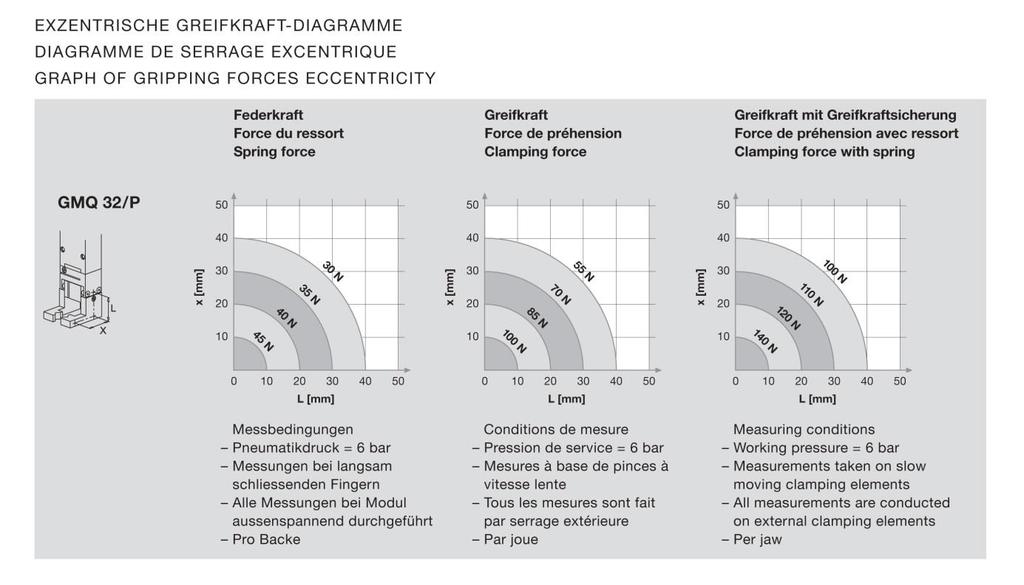
11 2.1.5 Gripper Diagramme GMQ 32 GMQ32; GMQ32-RM16/25-OI-vers. 2.5 gb

12 2.1.6 Preferred combinations GMQ GMQ32; GMQ32-RM16/25-OI-vers. 2.5 gb
13 3.0.0 Montage Instructions Manufacturer address: Afag Automation AG Fiechtenstrasse 32 CH-4950 Huttwil Sales Handling: Tel (0) These operating instructions apply to: Producte name: Gripper module / Rotary gripper module Types: GMQ 32 / GMK 32 GMQ 32/RM 16 GMQ 32/RM 25 Sequential series: No. 50xxxxxx This is an incomplete machine Who installs this incomplete machine or assemble with other machines, a risk assessment for its resulting machine which must make the provisions of the EC directive: 2006/42/EC Standard: EN ISO 12100:2010 (German version) Agent: For the compilation of the technically relevant documents: Niklaus Röthlisberger, Products Manager Afag Automation AG, CH-4950 Huttwil GMQ32; GMQ32-RM16/25-OI-vers. 2.5 gb
14 3.1.1 Symbols Assembly and initial start-up must be carried out by qualified personnel only and according to these Instructions. CAUTION Indicates a possibly dangerous situation. Non-compliance with this information can result in damage to property or light to medium personal injuries. NOTE Indicates general notes, useful operator tips and operating recommendations which don't affect safety and health of the personnel General description This is an incomplete machine The series of the GMQ 32 Gripper and (GMQ 32/RM 16/25 Rotary gripper module) is used for the Gripper and (Rotary gripper module) smooth movement of rigidly mounted loads under the ambient and Installation conditions defined, see Technical data. The Installation position of the GMQ 32 Gripper- and (GMQ 230RM 16/25 Rotary gripper module) can take place both vertically and horizontally. Modifications on the GMQ 32 and GMQ 32/RM 16/25 module that are not described in these Montage Instructions or have not been approved in writing by Afag Automation AG are not permitted. In case of improper changes or assembly, installation, operation, maintenance or repairs, Afag Automation AG rejects all liability. 14 GMQ32; GMQ32-RM16/25-OI-vers. 2.5 gb
15 3.1.3 Description of the module GMQ 32 General These Montage Instructions describe Gripper Module GM 32 and Rotary gripper module GM 32/RM 16/25, which can be operated with different grippers. All Information in these Montage Instructions relates to the above-mentioned types. NOTE Special mention is given to type-specific information. Gripper module GMQ 32 The pneumatically actuated GM 32 Gripper Module (piston Ø 32mm), together with a gripper, are designed for gripping small parts. The GMQ 32 is designed for outer tensioning (Fig.1), inner tensioning (Fig.2), or double-acting (Fig.3). An integrated spring (1) serves as clamping force protection in the unpressurized condition. All GM s are delivered from the factory with outer tensioning (Fig.1) and can be modified to a different function as necessary. GMQ32; GMQ32-RM16/25-OI-vers. 2.5 gb
16 3.1.4 Description of the rotary gripper module GMQ 32/RM 16/25 1 Gripper 5 Pneumatic connection RM Rotary module Gripper actuator Angle the mounting 6 7 Pneumatic connection, Gripper actuator Adjusting stop screw 8 Proximity switch (not included in the delivery) The rotary gripper module consists of a gripper (1), and rotary module (2), and the Gripper actuator (3) and the mounting angle (4). Connection (5) with the pneumatically on rotary module (6) and the connection on the gripper actuator. The final positions will each have a stop screw (7) is et. For sensing the end positions, the stop screw can be equipped with a proximity switch proximity switch holder and a 6.5mm. (not included in the delivery) The movement in the end of travel can also be buffered by the hydraulic stop absorber. (Rotary gripper module with shock absorber must be ordered separate). 16 GMQ32; GMQ32-RM16/25-OI-vers. 2.5 gb
17 3.1.5 Included in the delivery GMK 32 / GMQ 32 Number Description 2 Centering bushings 9x4 mm 2 2 Mounting screw M6x50 U-Disk M Designated use The series of the GMQ 32, GMK 32 gripper module and GMQ 32/ RM16/25 rotary gripper module is used for the movement of rigidly mounted loads in non-explosion harzadous ambient and Installation conditions that are specified for this module; see catalogue Safety Instructions NOTE These Montage Instructions should be read carefully before carrying out any activity on or with the module. The module may only be deployed in accordance with the intended use. Modifications on the module that are not described in these Montage Instructions or have not been approved in writing by Afag are not permitted. In case of improper changes or assembly, installation, operation, maintenance or repairs, Afag rejects all liability. CAUTION Connection of compressed air and operation of pneumatic systems may cause unpredictable movement which may result in personal injury or damage to property. When connecting compressed air for the first time make sure that all air chokes are closed. Ventilate the system slowly. GMQ32; GMQ32-RM16/25-OI-vers. 2.5 gb
18 3.1.8 Included in the rotary gripper module GMQ 32/RM 16/25 Number Description Angle the mounting Mounting screw M6x25 Rip disc M6 Rip disc M5 Centering pin 9x4 mm Designated use The series of the GMQ 32, GMK 32 gripper module and GMQ 32/ RM16/25 rotary gripper module is used for the movement of rigidly mounted loads in non-explosion harzadous ambient and operating conditions that are specified for this module; see catalogue Safety Instructions NOTE These Montage Instructions should be read carefully before carrying out any activity on or with the module. The module may only be deployed in accordance with the intended use. Modifications on the module that are not described in these Montage Instructions or have not been approved in writing by Afag are not permitted. In case of improper changes or assembly, installation, operation, maintenance or repairs, Afag rejects all liability. CAUTION Connection of compressed air and operation of pneumatic systems may cause unpredictable movement which may result in personal injury or damage to property. When connecting compressed air for the first time make sure that all air chokes are closed. Ventilate the system slowly. 18 GMQ32; GMQ32-RM16/25-OI-vers. 2.5 gb
19 3.2.1 Warranty The module is designed for 40 million load alternations* under the ambient conditions and conditions of use defined for this module, see catalogue. Wearing parts (shock absorbers and stop screws) are excluded from the warranty. The warranty includes repair or replacement of faulty Afag parts. *whichever comes first When repairs are carried out by the customer without prior training or instruction by Afag AG the warranty will become void. Any additional claims are excluded Areas of application The GMQ 32/GMK 32 are exclusively for the resort in any situation of load until a maximum of N, which the manipulation is not people, property and environmental hazard response. But they can also be combined with other modules as pick and place station used with the allowable loads must not be exceeded. Any other use is regarded as inadequate. NOTE The manufacturer does not accept any liability for damage resulting from such use. The risk is that of the user alone. Intended use also includes paying attention to the Montage Instructions and observing the maintenance and repair instructions specified by the manufacturer. The GM gripper and GM rotary gripper module may only be operated and serviced by correspondingly trained personnel who have also profound knowledge of the dangers. CAUTION The applicable regulations for prevention of accidents and the other generally accepted safety-relevant and occupational safety and health regulations are to be followed. GMQ32; GMQ32-RM16/25-OI-vers. 2.5 gb


20 3.2.3 Dimensions drawing GMK 32 / GMQ GMQ32; GMQ32-RM16/25-OI-vers. 2.5 gb


21 3.2.4 Technical data of the GMK 32 / GMQ 32 GMQ32; GMQ32-RM16/25-OI-vers. 2.5 gb
22 3.2.5 Dimensions drawing GMK 32 / GMQ GMQ32; GMQ32-RM16/25-OI-vers. 2.5 gb
23 3.2.6 Pneumatic connection GMK 32 / GMQ 32 1 Gripper actuator 4 Maintenance unit 2 One-way restrictor P Compressed air connection 3 Directional valve (Standard 5/ Pneumatic connection GMQ 32/RM 16/25 At the base of the rotary module are located on both sides of the pneumatic connections M5. Gripper actuator on the side are two pneumatic connections M5 1 Gripper actuator 4 Maintenance unit 2 One-way restrictor P Compressed air connection 3 Direction valve (standard 5/2) NOTE Minimal compressed air quality according to ISO ; 2010 (7-4-4) GMQ32; GMQ32-RM16/25-OI-vers. 2.5 gb

24 3.2.8 Adjusting the GMK 32 / GMQ 32 Afag AG achieves the following delivery conditions for the GM gripper modules. Gripper module The GM actuator and gripper can be delivered as individual modules, where the assembly is carried out by the customer, or as pre-assembled module by the factory. Gripper rotary module NOTE All GM s are delivered ex. Works with outer tensioning (unpressurized closed) and can be modified for a different function as necessary. Here, the GM, gripper and RM are adjusted to the desired combination and the module is optimally set at the factory. 24 GMQ32; GMQ32-RM16/25-OI-vers. 2.5 gb
25 3.2.9 Modifying the GMQ 32 to inner tension NOTE All GMs are delivered ex. Works with outer tensioning (unpressurized closed) and can be modified for a different function as necessary. Rotary gripper module Here, the rotary gripper module are adjusted to the desired combination and the module is optimally set at the factory. Modifiying the GMQ 32 to inner tension 1. Loosen screw (1+2) and remove the gripper (3). 2. Loosen screw (4+6) 3. Remove the pilot (7) 4. Pull out the piston (8) with the spring (9) and remove the travel stop (5). 5. Re-insert the piston (8) and spring (9) upside down and reassemble the module in the reverse order. 6. Functional check GMQ32; GMQ32-RM16/25-OI-vers. 2.5 gb
26 3.3.0 Modifying the GMQ 32 to double acting (Fig. 37) 1. Loosen screws (1+2) and remove the gripper (3). 2. Loosen screws (6) and remove the pilot (7). 3. Pult the spring (9). 4. Remount the pilot (7) with the countersunk screws (6). 5. Remount the gripper (3). 6. Functional check 26 GMQ32; GMQ32-RM16/25-OI-vers. 2.5 gb
27 3.3.1 Mounting of the gripper 1. Centering ring (5) in piston rod (6) introduce. 2. Centering bushings (1) on centering ring (5) positioning. 3. Centering bushings (1) rich and i insert gripper (2) 4. Gripper (2) with screw (4) and greased disc (3) on piston rod (6) of the gripper module. 5. Screw (7) tighten the gripper. 6. Functional check Gripper actuator Stroke adjustment on the gripper The gripper stroke can only be set on module GMQ. If the GMQ has been modified to inner tension or the spring removed, then the stroke stop (1) must be reconnected securely and flush to the piston rod (2). GMQ32; GMQ32-RM16/25-OI-vers. 2.5 gb
28 3.3.3 Adjustment the stop screw The GM 12 can be equipped with a wide variety of stop screws. These must be ordered separately. (see catalog technical) Adjusting stop screw AS 08/15 These stop screws can be combined with a proximity switch holder and proximity switch Ø 6.5 mm or with an angle proximity switch holder and 8x8 mm proximity switch for end of travel interrogation. 1. Set the stroke by adjusting the stop screw (5). 2. Secure the stop screw with counternut (6), (stopping accuracy +-0,01mm) Adjusting stop pin M8x1/25 1. Set the stroke by adjusting the stop pin (3). 2. Secure the stop pin with counternut (4), (stopping accuracy+-0,01 mm) 28 GMQ32; GMQ32-RM16/25-OI-vers. 2.5 gb
29 3.3.6 Adjusting the proximity switch Plug-in and screw-in Ø 65 mm or 8x8 mm proximity switch holders are used for interrogation of the end of travel. CAUTION GMs and proximity switch must not be used in an explosive environment! NOTE Proximity switches and holders are not included in the GM scope of delivery. CAUTION The proximity switches can only be used with series AS stop screws. Depending on the type of control, switch type PNP or NPN should be defined. An LED on the proximity switch serves function monitoring on end of travel interrogation. If the LED does not change is switching condition on end of travel interrogation, then the proximity switch is faulty and must be replaced! Technical data Operating voltage range VDC Switching interval 1,5 mm GMQ32; GMQ32-RM16/25-OI-vers. 2.5 gb
30 3.3.7 Montage Initiator 6,5 mm GMQ Screw the proximity switch holder (1) onto the stop screw. 2. Plug the proximity switch (2) as far as it will go into the proximity switch holder 3. Slightly tighten the proximity switch holder (1). 4. Mount the cover (3). 5. Mount the plug (4). 6. Functional check. 30 GMQ32; GMQ32-RM16/25-OI-vers. 2.5 gb
31 3.3.8 Montage proximity switch 8x8 mm the GMQ Screw the proximity switch (5) onto the proximity switch holder (7) with screws (6). 2. Mount the cover (10) 3. Plug the proximity switch holder (7) with proximity switch as far as it will go onto the stop screw (8) and lock with screw (9). 4. Mount the plug (4) 5. Functional check. CAUTION The switching point of the proximity switch must cover the drill hole of the proximity switch holder! (see arrow) GMQ32; GMQ32-RM16/25-OI-vers. 2.5 gb
32 3.3.9 Preparation for start-up Before you start the shock absorber and the stop screw so that the proposed rotation-stroke is damped properly Start-up of the GM 32 (GM 32/RM 16/25) Aerate the total system slowly. Pay attention to the permissible values (technical data) regarding: - load capacity - motion frequency - moment loads on the guide system CAUTION Limbs may be squeezed by moving components. Make sure that there are no persons or tools within the operating range of the module. Carry out a test run - at first at slow traverse speed, - afterwards under operating conditions. 32 GMQ32; GMQ32-RM16/25-OI-vers. 2.5 gb
33 4.0.0 Maintenance Instruction Maintenance and servicing CAUTION The module may only be disassembled when the system is aerated and deactivated. If pneumatic connections are disconnected when they are under pressure, this may result in serious personal injury due to fast movements of moving parts. Maintenance interval Service measures As required Clean the module with a dry, lint-free cloth. The module must not be washed down; do not use any aggressive cleaners. 1 Montly Check the safety labels for damage, readability and cleunless. Further maintenance Under the following conditions is the GM gripper and GM/RM rotary gripper module maintenance free: Clean workshop atmosphere No splash water No dust and fumes caused by abraison or processes Ambient conditions according the Maintenance Instructions GMQ32; GMQ32-RM16/25-OI-vers. 2.5 gb
34 4.1.1 The GM gripper and GM/RM rotary gripper module is lubricated for-life and can be operated with oiled and unoiled air. CAUTION Never operate the GM gripper and GM/RM rotary gripper module with unoiled air after it was operated with oiled air! Air characteristics: Dry (free from condensation water) Filtered (40µm filter for oiled air) Filtered (5µm filter for unoiled air) If the GM gripper and GM/RM rotary gripper module is operated with oiled air, the oil types listed below should be used: Festo special oil Avia Avilub RSL 10 BP Energol HPL 10 Esso Spinesso 10 Shell Tellus Oil C 10 Mobil DTE 21 Blaser Blasol 154 Oil quantity: 5 10 oil drops per 1000 l air Viscosity range: 9 to 11 mm²/s (= cst) at 40 C, ISO-class VG 10 according to ISO 3448 Apart from the usual cleaning work no further maintenance measures are required. NOTE Module inserts for ionized air environments (e.g. in case of highvoltage procedures such has corona processes) Open guides and piston rods should be covered with a grease layer to avoid formation of rust. Afag standard greasing: - Staburax NBU8EP (flat guides) - Blasolube 301 (piston rods) 34 GMQ32; GMQ32-RM16/25-OI-vers. 2.5 gb
35 4.1.2 Trouble-shooting GMK 32 / GMQ 32 and GMQ 32/RM 16/25 Defective components are only to be replaced by Afag original spare parts. Fault Possible cause Fault clearance Gripper opens does not close End position does not exist Compressed air is missing Module pneumatically connected incorrectly Stop screw incorrectly adjusted Check over the connections Check connections Stop screw adjust Proximity switch defective Proximity switch exchange Hard gripping the workpiece Gripper cannot grasp the part, or lose it. Grip strength to high Low Open circuit in the sensor cable Defective exhaust valve Gripper speed too high Mass of the workpiece is too high Cross point of the gripper tongs too far except of Construction of the gripper fingers non-optimal -maximum gripper force -mean grip strength Initiator replace cable Replace exhaust valve Adjust exhaust valve Greater use gripper type Pressure shift inward Construction customize (engage positifely) Pneumatic + spring action = gripping force safety Only pneumatic -slightest grip force only spring action GMQ32; GMQ32-RM16/25-OI-vers. 2.5 gb
36 4.1.3 Accessories GMK 32 / GMQ 32; GMQ 32/RM 16/25 Description Order No. Stop screw AS 08/ Stop screw AS 08/ Centering pin M8x1/ Shock absorber SD 08/ Proximity switch INI d6.5x44-sn1.5-pnp-no- M8x1 Proximity switch INI 8x8x38.5-Sn2.0-PNP-NO- M8x GMQ32; GMQ32-RM16/25-OI-vers. 2.5 gb
37 4.1.4 Disassembly and repair When the module is damaged it can be returned to Afag AG for repair. CAUTION The module may only be disassembled when the system is ventilated and deactivated. If pneumatic connections are disconnected when they are under pressure, this may result in serious personal injury owing to fast movements of moving parts. When can the modules be repaired by the customer? Wearing parts can be exchanged by the customer itself when the warranty has expired. NOTE All the other faulty parts must exclusively be replaced by company Afag AG! When the customer detects that the respective module is still under warranty? - He returns the module to company Afag AG for repair. - If the warranty has already expired, the customer must decide whether he repairs the module himself and orders the wearing parts kit or whether he returns the module to company Afag AG for repair. NOTE The Afag offers a reliable repair service. Note that Afag no warranty of modules can take over what the company does not furch Afag Automation AG have been repaired. GMQ32; GMQ32-RM16/25-OI-vers. 2.5 gb
38 4.1.5 Spare parts GMQ 32 Pos Spare parts Dimensions Supplier Qty. Order No. 1 Housing Afag Piston Afag Rod Afag Pilot Afag Travel stop Afag Bearing bush Afag Protection Afag Compression spring Afag Piston packing Afag Rod packing Afag O-Ring D 29x1.5 mm Afag Countersunk allen screw M4x20 mm Afag Countersunk allen screw M4x12 mm Afag Setscrew M4x30 mm Afag Centering bushings D 9x4 mm Afag Gripper fastening set Afag 1 Seal set Sel seat for GM 32 the positions 9,10,11 Order No GMQ32; GMQ32-RM16/25-OI-vers. 2.5 gb
39 4.1.6 Spare parts for GMK 32 Pos Spare parts Dimensions Supplier Qty. Order No. 1 Housing Afag Piston Afag Rod Afag Pilot Afag Housing cover Afag Thread plug Afag Ribbed washer M4 Afag Compression spring Afag Piston packing Afag Rod packing Afag O-Ring D 29x1.5 mm Afag Countersunk allen screw M4x20 mm Afag Countersunk allen screw M4x12 mm Afag Setscrew M5x20 mm Afag Centering bushings D 4x6 mm Afag Gripper fastening set Afag 1 Seal set Sel seat for GM 32 the positions 9,10,11 Order No GMQ32; GMQ32-RM16/25-OI-vers. 2.5 gb

40 4.1.7 Rotary Gripper Module GMQ 32/RM 16/25 You can put together our gripper rotary module complete with the desired gripper tongs at Afag Automation AG. Detailed information can be found in our handling catalog or WEB GMQ32; GMQ32-RM16/25-OI-vers. 2.5 gb
41 4.1.8 Dimension GMQ 32 /RM 16/25 GMQ32; GMQ32-RM16/25-OI-vers. 2.5 gb
42 4.1.9 Product overview GMQ 32/RM16/25 42 GMQ32; GMQ32-RM16/25-OI-vers. 2.5 gb
43 4.2.0 Parts drawing GMQ 32/RM 16 The gripper module series GMQ can also Afag with rotary gripper modules of the RM 16 and RM 25 series fit together. CAUTION For gripper fingers, the length (L9 as well as the offset (X) should not exceed the recommended dimensions in the clamping force diagrams. The GMQ 32 module can be mounted just behind the RM 16725th The gripping position can be monitored with the initiators. GMQ32; GMQ32-RM16/25-OI-vers. 2.5 gb
44 4.2.1 Accessories RM 16 Accessories RM 16 Order No. Torque amplifier for RM Cylinder intermediate position for RM Cylinder intermediate position for RMZ 16/ Accessories intermediate position range for RM Accessories shock absorbers RM Mounting screw M6x56 mm Proximity switch INI d6.5x44-sn1.5-pnp-no-m8x Proximity switch INI 8x8x38.5-Sn2.0-PNP-NO-M8x Accessories RM 25 Order No. Mounting screw M6x56 mm Clamping support RM 16/RM INI d6.5x44-sn1.5-pnp-no-m8x INI 8x8x38.5-Sn2.0-PNP-NO-M8x GMQ32; GMQ32-RM16/25-OI-vers. 2.5 gb

45 4.2.2 Spare parts for RM 16 Pos Spare parts Dimensions Supplier Qty. Order No. 1 Expendable parts Afag Expendable parts Afag GMQ32; GMQ32-RM16/25-OI-vers. 2.5 gb
46 4.2.3 Spare parts for RM 16/360 Pos Spare parts Dimensions Supplier Qty. Order No. 1 Expendable parts Afag Expendable parts Afag GMQ32; GMQ32-RM16/25-OI-vers. 2.5 gb

47 4.2.4 Spare parts for RM 25 / RMZ 25/1 Pos Spare parts Dimensions Supplier Qty. Order No. 1 Seal set Afag Seal set Afag Disposal NOTE GM /RM which are of no further use should not be disposed to fas a complete unit but dismantled into individual parts according to the type of material and recycled should be correctly disposed of. Non-recyclable materials, animal waste. GMQ32; GMQ32-RM16/25-OI-vers. 2.5 gb
48 Afag Automation AG Fiechtenstrasse 32 CH Huttwil Switzerland Tel.: Fax.: sales@afag.com Internet: 48 GMQ32; GMQ32-RM16/25-OI-vers. 2.5 gb
Gripper Module GMK 20 / GMQ 20 Rotary Gripper Modules GMQ 20-RM 16/GMQ 20-RM 25
 Gripper Module GMK 20 / GMQ 20 Rotary Gripper Modules GMQ 20-RM 16/GMQ 20-RM 25 - Declaration of Incorporation - Module Information - Montage Instructions - Maintenance Instructions Translation of the
Universal Gripper UG 20, UG 25
 Universal Gripper UG 20, UG 25 - Declaration of Incorporation - Module Information - Montage Instructions - Maintenance Instructions Translation of the Original Montage Instructions copyright by Afag Automation
Gripper Modules GMQ 12
 Gripper Modules GMQ 12 Rotary gripper modules GMQ 12-RM 12 - Declaration of Incorporation - Module Information - Montage Instructions - Maintenance Instructions Translation of the Original Montage Instructions
- Declaration of Incorporation - Module Information - Montage Instructions - Maintenance Instructions
 Compact Slide CS 8 / CS 12 - Declaration of Incorporation - Module Information - Montage Instructions - Maintenance Instructions Translation of the Original Montage Instructions Copyright by Afag Automation
Rotary modules CR 12 / CR 16 / CR 20
 Rotary modules CR 12 / CR 16 / CR 20 - Declaration of Incorporation - Module Information - Montage Instructions - Maintenance Instructions Translation of the Original Montage Instructions Copyright by
Rotary module CR 25 I CR 32. Declaration of Incorporation Module Information Montage Instructions Maintenance Instructions
 Rotary module CR 25 I CR 32 Declaration of Incorporation Module Information Montage Instructions Maintenance Instructions Translation of the Original Montage Instructions Copyright by Afag Automation AG
Rotary Module RM 25 und RM 32
 Rotary Module RM 25 und RM 32 - Declaration of Incorporation - Module Information - Montage Instructions - Maintenance Instructions Translation of the Original Montage Instructions Copyright by Afag Automation
Gripper-rotations module GM 20 - RM 16 GM 20 - RM 25. Operating instructions....automatisch gut!
 Gripper-rotations module GM 20 - RM 16 GM 20 - RM 25 Operating instructions...automatisch gut! These operating instructions apply to: Type GM 20 Type RM 16 / RM 25 GMK 20/P RM 16 GMK 20/2 GMK 20/K GMK
Gripper-rotary module GM 32 - RM 16 GM 32 - RM 25. Operating instructions....automatisch gut!
 Gripper-rotary module GM 32 - RM 16 GM 32 - RM 25 Operating instructions...automatisch gut! These operating instructions apply to: Type GM 20 Type RM 16 / RM 25 GMK 32/P RM 16 GMK 32/2 GMK 32/K GMK 32/3
Linear modules LM 20 and LM 25
 Linear modules LM 20 and LM 25 - Declaration of Incorporation - Module Information - Montage Instructions - Maintenance Instructions Translation of the Original Montage Instructions Copyright by Afag Automation
Linear modules LM 32
 Linear modules LM 32 - Declaration of Incorporation - Module Information - Montage Instructions - Maintenance Instructions Translation of the Original Montage Instructions Copyright by Afag Automation
Telescope spindle axis SA-3 / SA-6
 Telescope spindle axis SA-3 / SA-6 - Declaration of Incorporation - Module Information - Montage Instructions - Maintenance Instructions Translation of the Original Montage Instructions Copyright by Afag
Telescope spindle axis SA-1
 Telescope spindle axis SA-1 - Declaration of Incorporation - Module Information - Montage Instructions - Maintenance Instructions Translation of the Original Montage Instructions Copyright by Afag Automation
Bowl feeder WV401-1 / Translation of operating and installation instructions
 Bowl feeder WV401-1 / 402-1 Translation of operating and installation instructions Copyright by Afag GmbH This operation instruction applies to: Bowl feeder WV401-1 Bowl feeder WV402-1 Type 230 V / 50
Bowl Feeder BF10 / BF15 Translation of original operating instruction
 Bowl Feeder BF10 / BF15 Translation of original operating instruction Copyright by Afag GmbH This operation instruction applies to: Bowl feeder right 12 Bowl feeder left 12 Type Order number BF10 BF15
Bowl Feeder BF10 / BF15 Translation of operating and installation instructions
 Bowl Feeder BF10 / BF15 Translation of operating and installation instructions Copyright by Afag GmbH This operation instruction applies to: Bowl feeder right 12 Bowl feeder left 12 Type Order number BF10
Bowl feeder BF20 / BF25 / BF30 BF35 / BF40 / BF50
 Bowl feeder BF20 / BF25 / BF30 BF35 / BF40 / BF50 Translation of original operating instruction Copyright by Afag GmbH This operation instruction applies to: Type Order number BF20 BF25 BF30 BF35 BF40
Swiveling gripper finger GFS 16-40
 Translation of the original manual Swiveling gripper finger GFS 16-40 Assembly and Operating Manual Superior Clamping and Gripping Imprint Imprint Copyright: This manual remains the copyrighted property
Bowl feeder BF20 / BF25 / BF30 BF35 / BF40 / BF50
 Bowl feeder BF20 / BF25 / BF30 BF35 / BF40 / BF50 Translation of operating and installation instructions Copyright by Afag GmbH This operation instruction applies to: Type Order number BF20 BF25 BF30 BF35
Compensation unit AGE-XY 50-80
 Translation of the origninal manual Compensation unit AGE-XY 50-80 Assembly and operating manual Superior Clamping and Gripping Imprint Imprint Copyright: This manual remains the copyrighted property of
Power Transmission. Installation and Operating Instructions for Brake Caliper DH 010 PFK. E e.
 Power Transmission Installation and Operating Instructions for Schaberweg 30-34 Telephone +49 6172 275-0 61348 Bad Homburg Telefax +49 6172 275-275 Germany www.ringspann.com mailbox@ringspann.com Date:
2-finger parallel gripper GM
 Translation of the Original operating manual 2-finger parallel gripper GM 80-201 Assembly and Operating Manual Superior Clamping and Gripping Imprint Imprint Copyright: This manual remains the copyrighted
Assembly and Maintenance Manual Type ASNU
 Assembly and Maintenance Manual Type ASNU Hatschekstr.36 69126 Heidelberg Germany Tel +49(0)6221 30470 Fax +49(0)6221 304731 info@stieber.de www.stieber.de Date of issue: 30.05.2018 GB Revision: 0 U:\EngUsers\!ProduktDoku\1AAA_Einbauerklaerung_Wartungsanleitung_Konformitaetserklaerung\1AAA_Wartungsanleitungen\Orginal_Worddatei\_ASNU.docx
Assembly and Maintenance Manual Type AS
 Assembly and Maintenance Manual Type AS Hatschekstr.36 69126 Heidelberg Germany Tel +49(0)6221 30470 Fax +49(0)6221 304731 info@stieber.de www.stieber.de Date of issue: 30.05.2018 GB Revision: 0 U:\EngUsers\!ProduktDoku\1AAA_Einbauerklaerung_Wartungsanleitung_Konformitaetserklaerung\1AAA_Wartungsanleitungen\Orginal_Worddatei\_AS.docx
2-finger angular gripper PWG
 Original operating manual 2-finger angular gripper PWG 65-230 Assembly and operating manual Superior Clamping and Gripping Imprint Imprint Copyright: This manual remains the copyrighted property of SCHUNK
2-Finger-Angular Gripper LGW 10-40
 Translation of the orginial manual 2-Finger-Angular Gripper LGW 10-40 Assembly- and Operating Manual Superior Clamping and Gripping Imprint Imprint Copyright: This manual remains the copyrighted property
Small gripper with large stroke KGG
 Translation of the original manual Small gripper with large stroke KGG 220-280 Assembly and Operating Manual Superior Clamping and Gripping Imprint Imprint Copyright: This manual remains the copyrighted
Double piston rotary drive DRQD-6/... / b [ ] (en) Operating instructions
![Double piston rotary drive DRQD-6/... / b [ ] (en) Operating instructions](/thumbs/95/124095546.jpg "Double piston rotary drive DRQD-6/... / b [ ] (en) Operating instructions") Double piston rotary drive (en) Operating instructions 8068584 2017-05b [8068586] Original instructions Symbols: Warning, Caution Fitting and commissioning to be carried out by qualified personnel only
Double piston rotary drive (en) Operating instructions 8068584 2017-05b [8068586] Original instructions Symbols: Warning, Caution Fitting and commissioning to be carried out by qualified personnel only
Vibratory hopper unit NVD 3 / NVD 4 Translation of operating and installation instructions
 Vibratory hopper unit NVD 3 / NVD 4 Translation of operating and installation instructions Copyright by Afag GmbH This operation instruction applies to: NVD3/5 NVD4/10 NVD4/15 NVD4/20 NVD4/40 5,0 Liters
2-Finger-Parallel-Gripper PFH
 Translation of the Original Manual 2-Finger-Parallel-Gripper PFH 150-300 Assembly and Operating Manual Superior Clamping and Gripping Imprint Imprint Copyright: This manual remains the copyrighted property
Operating Instructions. Handling Components Grippers GPU / GPUI BA ENGLISH
 Operating Instructions Handling Components Grippers GPU / GPUI BA-100008 ENGLISH Edition: 10/2005 Operating Instructions GPU / GPUI Change index Previous editions: Edition Note Reference number 10/2005
2-finger radial gripper LGR 10-40
 Translation of the original manual 2-finger radial gripper LGR 10-40 Assembly and Operating Manual Superior Clamping and Gripping Imprint Imprint Copyright: This manual remains the copyrighted property
Pneumatic Swivel Unit SRU 20-60
 Translation of the original manual Pneumatic Swivel Unit SRU 20-60 Assembly and operation manual Superior Clamping and Gripping Imprint Imprint Copyright: This manual remains the copyrighted property of
HST -LS Interlocking device (Translation of Original Manual)
") Installation and Operating Manual for Components HST -LS Interlocking device (Translation of Original Manual) HST-LS Ident.-No.: 10268 HST-LS Ident.-No.: 10269 HST-LS, pictured Ident-Nr. 10269 The image
Installation and Operating Manual for Components HST -LS Interlocking device (Translation of Original Manual) HST-LS Ident.-No.: 10268 HST-LS Ident.-No.: 10269 HST-LS, pictured Ident-Nr. 10269 The image
Assembly and operating manual AGE-W Angular Compensation Unit
 original manual Assembly and operating manual AGE-W Angular Compensation Unit Imprint Imprint Copyright: This manual is protected by copyright. The author is SCHUNK GmbH & Co. KG. All rights reserved.
These operating instructions apply for: NCX 380 NCZ 300 NCX 480 NCZ 370 NCX 580 L NCZ 480 NCX 660 K NCZ 560 NCZ 660 NCZ 800
 Original instructions Operating Instructions for May 2010 Electric Internal Vibrators BA No. 1092E Series NCX and NCZ These operating instructions apply for: NCX 380 NCZ 300 NCX 480 NCZ 370 NCX 580 L NCZ
KONEX Pneumatic Modular Gripping System KONEX Gripping force Torque Piston force (extended)
") KONEX Gripping force 100 N Torque 0.9 Nm Piston force (extended) 250 N Application example KONEX weight-reduced, modular gripping system for economical automation in assembly and production KONEX P 50
KONEX Gripping force 100 N Torque 0.9 Nm Piston force (extended) 250 N Application example KONEX weight-reduced, modular gripping system for economical automation in assembly and production KONEX P 50
Pneumatic rotary actuator SRH-plus 20-60
 Translation of the Original operating manual Pneumatic rotary actuator SRH-plus 20-60 Assembly and Operating Manual Superior Clamping and Gripping Imprint Imprint Copyright: This manual remains the copyrighted
Assembly and Maintenance Manual Type RSBW
 Assembly and Maintenance Manual Type RSBW Hatschekstr. 36 69126 Heidelberg Germany Tel +49(0)6221 30470 Tel +49(0)6221 304731 info@stieber.de www.stieber.de Stieber Clutch Date of issue: 16/03/2017 GB
Operating and installation instructions
 Pneumatic actuators DP34 Tandem / DP34 Tridem DP34T Contents DP34Tri 1.0 General information on operating instructions...2-2 2.0 Notes on possible dangers...2-2 2.1 Significance of symbols...2-2 2.2 Explanatory
Type Operating Instructions. Bedienungsanleitung Manuel d utilisation. 2/2-way solenoid valve 2/2-Wege-Magnetventil Électrovanne 2/2 voies
 Type 5404 2/2-way solenoid valve 2/2-Wege-Magnetventil Électrovanne 2/2 voies Operating Instructions Bedienungsanleitung Manuel d utilisation Contents 1 Operating instructions...2 2 Intended use...3 3
Pneumatic Radial gripper PRG
 Translation of the original manual Pneumatic Radial gripper PRG 26-125 Assembly and Operating Manual Superior Clamping and Gripping Imprint Imprint Copyright: This manual remains the copyrighted property
Planar surface gantry EXCM-30. Instructions. Mechanical installation b [ ]
![Planar surface gantry EXCM-30. Instructions. Mechanical installation b [ ]](/thumbs/91/106333591.jpg "Planar surface gantry EXCM-30. Instructions. Mechanical installation b [ ]") Planar surface gantry EXCM-30 Instructions Mechanical installation 804447 605b [8044434] EXCM-30 Translation of the original instructions LOCTITE is a registered trademark of its respective trademark holder
Planar surface gantry EXCM-30 Instructions Mechanical installation 804447 605b [8044434] EXCM-30 Translation of the original instructions LOCTITE is a registered trademark of its respective trademark holder
Pneumatic Swivel Unit SRU-plus 20-60
 Translation of the original manual Pneumatic Swivel Unit SRU-plus 20-60 Assembly and Operating Manual Superior Clamping and Gripping Imprint www.comoso.com Imprint Copyright: This manual remains the copyrighted
Power Transmission. Installation and Operating Instruction for Brake Caliper DU 060 PFM. E e.
 Power Transmission Installation and Operating Instruction for E 09.680e Schaberweg 30-34 Telephone +49 6172 275-0 61348 Bad Homburg Telefax +49 6172 275-275 Germany www.ringspann.com mailbox@ringspann.com
AC 100. Operating instructions Pneumatic Crimper AC 100. Date of issue: 05/2010. Keep for future use!
 Operating instructions Pneumatic Crimper AC 100 Date of issue: 05/2010 Keep for future use! SAFETY SAFETY Basic information The basic prerequisite for ensuring safe use and continuous operation of the
2-Finger Parallel Gripper KGG
 Translation of the original manual 2-Finger Parallel Gripper KGG 60-20... 140-60 Assembly and Operating Manual Superior Clamping and Gripping Imprint Imprint Copyright: This manual remains the copyrighted
Safety Shock Absorbers SCS33 to SCS64
 Safety Shock Absorbers SCS33 to SCS64 1 Operating Instruction SCS33-25EU SCS33-50EU SCS45-25EU SCS45-50EU SCS45-75EU Rod Button SCS64-50EU SCS64-100EU SCS64-150EU Integrated Rod Seals Main Bearing Content
Operating and installation instructions
 DP30 DP32 DP33 DP34 Contents 1.0 General information on operating instructions... 2-2 2.0 Notes on possible dangers... 2-2 2.1 Significance of symbols... 2-2 2.2 Explanatory notes on safety information...
Assembly and Operating Manual PGN-plus 2-Finger Parallel Gripper
 Translation of the original manual Assembly and Operating Manual PGN-plus 2-Finger Parallel Gripper Imprint Imprint Copyright: This manual is protected by copyright. The author is SCHUNK GmbH & Co. KG.
KeContact P20. User manual
 KeContact P20 User manual Comments to this manual In this manual you will find warnings against possible dangerous situations. The used symbols apply to the following meanings:!! WARNING! Indicates a potentially
Linear unit, pneumatic KHM 40
 Translation of original operating manual Linear unit, pneumatic KHM 40 Assembly and Operating Manual Superior Clamping and Gripping Imprint Imprint Copyright: This manual remains the copyrighted property
original operating manual Operating manual Translation of the Item-No.: ,
 Translation of the original operating manual Operating manual Item-No.: 015 431 551, 015 431 581 Important! Copyright The operating manual is always to be read before commissioning the equipment. No warranty
Rotary feed-through DDF-S/-KS
 Translation of the Original Operating Manual Rotary feed-through DDF-S/-KS Assembly and Operating Manual Superior Clamping and Gripping Imprint Imprint Copyright: This manual remains the copyrighted property
Gripping rotary modules.
 Gripping rotary modules Gripping rotary modules GRIPPING ROTARY MODULES Series Size Page Gripping rotary modules RP 314 RP 1212 318 RP 1216 322 RP 1520 326 RP 2120 330 RP 2128 334 RC 338 RC 1212 342 RC
Type 3761 Pneumatic or Electropneumatic Positioner for Rotary Actuators. Fig. 1 Type 3761 Positioner. Mounting and Operating Instructions EB 8386 EN
 Type 3761 Pneumatic or Electropneumatic Positioner for Rotary Actuators Fig. 1 Type 3761 Positioner Mounting and Operating Instructions EB 8386 EN Edition July 2007 Contents Contents Page 1 Design and
FLENDER ARPEX Plate packs with close-fitting bolt connection. ARW-4 Sizes to Assembly instructions An 4239 en 12/2015.
 FLENDER ARPEX Plate packs with close-fitting bolt connection ARW-4 Sizes 101-4 to 292-4 Assembly instructions FLENDER couplings FLENDER ARPEX Plate packs with close-fitting bolt connection ARW-4 Sizes
Toothed belt axis ELGC-TB-KF. Operating instruction [ ]
![Toothed belt axis ELGC-TB-KF. Operating instruction [ ]](/thumbs/83/87984161.jpg "Toothed belt axis ELGC-TB-KF. Operating instruction [ ]") Toothed belt axis ELGC-TB-KF en Operating instruction 8068220 2017-02 [8068222] Original instructions Identification of hazards and instructions on how to prevent them: Danger Immediate dangers which can
Toothed belt axis ELGC-TB-KF en Operating instruction 8068220 2017-02 [8068222] Original instructions Identification of hazards and instructions on how to prevent them: Danger Immediate dangers which can
Pneumatic Swivel Unit Type SRU-plus 63
 Translation of the original manual Pneumatic Swivel Unit Type SRU-plus 63 Assembly and Operating Manual 01.01/SRU-plus63/en Imprint Copyright: This manual remains the copyrighted property of SCHUNK GmbH
Sealed Angle Gripper DWG 44-80
 Translation of the original manual Sealed Angle Gripper DWG 44-80 Assembly and Operating Manual Superior Clamping and Gripping Imprint Imprint Copyright: This manual remains the copyrighted property of
Installation and Operating Instructions for EAS -NC clutch Type 45_. _. _ Sizes 02 and 03
 Table of contents: Please read and observe this Operating Instruction carefully! A possible malfunction or failure of the clutch and any damage may be caused by not observing it. Page 1: - Table of contents
Technical Data Sheet TI-F55 Locking Units series KFHS (with DGUV approval)
") English translation of German original Technical Data Sheet TI-F55 Locking Units series KFHS (with DGUV approval) For a detailed functional description refer to Technical Information TI-F10. Further important
English translation of German original Technical Data Sheet TI-F55 Locking Units series KFHS (with DGUV approval) For a detailed functional description refer to Technical Information TI-F10. Further important
GSM. Modular Design. Versions of the series. Type GSM. Gripper type P Z W R. Size. {} AS IS without O.D. clamping I.D. clamping
 GSM Pneumatic Gripper-Swivel System Modular Design Versions of the series Type GSM Gripper type P Z W R Size 32 40 50 64 30 38 45 16 20 25 32 40 16 20 25 32 40 Gripping force safety device {} AS IS without
Stud Gun Automatic Stud Gun EP-8, EP-9, EP-10
 Stud Gun Automatic Operating instructions (ID-No. 00035102) 00100192 EP-8 (gun for manual use) 00101758 EP-8 (gun for machine) 00100193 EP-9 (gun for manual use) 00100262 EP-9 (gun for machine) assembled:
FLENDER ZAPEX couplings. Type ZWT. Operating instructions BA 3505 EN 10/2011. FLENDER couplings
 FLENDER ZAPEX couplings Type ZWT Operating instructions FLENDER couplings FLENDER ZAPEX couplings Type ZWT Operating instructions Translation of the original operating instructions Technical data Notes
Electropneumatic Converters i/p Converters Type 6111 Mounting and Operating Instructions EB 6111 EN
 Electropneumatic Converters i/p Converters Type 6111 Fig. 1 Type 6111 in standard version Fig. Type 6111 mounted on a supply air manifold Fig. 3 Type 6111 in field enclosure Mounting and Operating Instructions
Drive Unit e-drive1. Installation instructions 04/2014. English translation of the original German installation instructions
 Drive Unit e-drive1 Installation instructions 04/2014 English translation of the original German installation instructions Contents Foreword... 3 Availability... 3 Structural features in the text... 3
RO Automatic trailer coupling. Repair instructions. 5KPVM02000 Towing Hitch Automatic Rockinger RO244A
 utomatic trailer coupling Repair instructions 5KPVM02000 Towing Hitch utomatic Rockinger RO244 5KPVM02010 Towing Hitch utomatic Rockinger foot operated RO244L Contents 1 General Validity and application
Exchange of rollers from the XTS-Mover
 Service documentation for AT901-0050-0550 and AT9011-00x0-0550 Version: Date: 1.0 0.10.017 Table of contents Table of contents 1 Foreword... 5 1.1 Notes on the documentation... 5 1. Documentation issue
Angle seat valve with diaphragm actuator VZXA-...-M
 Angle seat valve with diaphragm actuator VZXA-...-M Instructions Operating (Translation of the original instructions) Festo AG & Co. KG Ruiter Straße 82 73734 Esslingen Germany +49 711 347-0 www.festo.com
Operating Instructions
 Armaturen GmbH Armaturen, Rohre, Sonderteile aus Edelstahl fittings, pipes, special parts of stainless steel Operating Instructions BaseCom butterfly valve Rev.0 / 12.12.2009 Page 1 of 8 BA52290GB.doc
Installation and Operating Instruction for Brake Caliper HW 150 HFA and HW 180 HFA E e
 Installation and Operating Instruction for Brake Caliper HW 150 HFA and HW 180 HFA E 09.736e Schaberweg 30-38 Phone +49 6172 275-0 61348 Bad Homburg Fax +49 6172 275-275 Germany www.ringspann.com info@ringspann.com
Angle seat valve with piston actuator VZXA-...-K
 Angle seat valve with piston actuator VZXA-...-K Instructions Operating (Translation of the original instructions) Festo AG & Co. KG Ruiter Straße 82 73734 Esslingen Germany +49 711 347-0 www.festo.com
Printed: Doc-Nr: PUB / / 000 / 00
 ORIGINAL OPERATING INSTRUCTIONS Hilti HTE-P 33 dispenser It is essential that the operating instructions are read before the tool is operated for the first time. Always keep these operating instructions
Operating manual Separator
 Operating manual Separator Sheet no. AS/4.1.141.1.1 issue 20.08.2014 Contents Section Title Page 0 Introduction... 1 1 Intended use......1 2 Marking of the fitting... 1 3 Safety instructions... 2 4 Transport
Mounting and Operating Instructions EB EN. Type 3372 Electropneumatic Actuator. Actuator area: 120 and 350 cm² With Type 3725 Positioner
 Type 3372 Electropneumatic Actuator Actuator area: 120 and 350 cm² With Type 3725 Positioner Translation of original instructions Type 3372 with 120 cm² actuator area Type 3372 with 350 cm² actuator area
Support T10552 T10595 T40386
 T10552 T10595 T40386 en-gb 7 T10552 T10595... 1 General Information Product name: Product type: Product number: Weight: Max. load capacity: Static test coefficient: 3.0 Intended Use: Load holding device
Rotary feed-through DDF 2
 Translation of the original operating manual Rotary feed-through DDF 2 Assembly and Operating Manual Superior Clamping and Gripping Imprint Imprint Copyright: This manual remains the copyrighted property
Original Operating Manual
 matev GmbH Nürnberger Str. 50 90579 Langenzenn T +49 (0) 9101 9087-0 F +49 (0) 9101 9087-20 info@matev.eu www.matev.eu Original Operating Manual Snow blade SRM-FB 120 CD Angle adjustment mechanical Version
Stacking gripper SG 47
 Original operating manual Stacking gripper SG 47 Assembly and operating manual Superior Clamping and Gripping Imprint Imprint Copyright: This manual remains the copyrighted property of SCHUNK GmbH & Co.
2-Finger Parallel Gripper PGM
 Translation of the original manual 2-Finger Parallel Gripper PGM 29-140 Assembly- and Operating Manual Superior Clamping and Gripping Imprint Imprint Copyright: This manual remains the copyrighted property
SFL. Application example. Pneumatic Rotary Actuators Rotor. Weight kg. Axial force N. Sizes 25..
 SFL Sizes 25.. 64 Weight 0.09.. 0.71 kg Torque 0.12 Nm.. 3.9 Nm Axial force 10.. 50 N Bending moment 0.1.. 0.5 Nm Application example Sorting unit with SFL rotor to drive the separator switch Rotor SFL
Compact Linear Module CLM
 Translation of the original manual Compact Linear Module CLM Assembly and operating manual Superior Clamping and Gripping Translation of the original manual Imprint: Copyright: This manual remains the
Angle seat valve with piston actuator VZXA-...-K
 Angle seat valve with piston actuator VZXA-...-K Festo AG & Co. KG Postfach 73726 Esslingen Germany +49 711 347-0 www.festo.com 3 Further information Accessories www.festo.com/catalogue Spare parts www.festo.com/spareparts
DIAPHRAGM LIQUID PUMP NF 1.30
 DIAPHRAGM LIQUID PUMP NF 1.30 NF 1.30 KT DCG 12V Supply voltage [Ch. 4] DCG KT / TT [Ch. 4] 1.30 NF - / PMLxxxx / PLxxxx [Ch. 1] Operating and Installation Instructions Read and observe these Operating
Pneumatic rotary actuator SRH-plus 20-60
 Translation of the Original operating manual Pneumatic rotary actuator SRH-plus 20-60 Assembly and Operating Manual Superior Clamping and Gripping Imprint Imprint Copyright: This manual remains the copyrighted
Hydraulic Multi-Disc Brake H420 P-2067-WE SM320gb - rev 02/09
 Hydraulic Multi-Disc Brake H420 P-2067-WE SMgb - rev 02/09 Service Manual We, WARNER ELECTRIC EUROPE, 7, rue Champfleur, B.P. 20095, F-49182 St Barthélemy d Anjou Cedex declare that the brakes made in
MECHANICAL CYLINDERS Operating Instructions
 SW3001EN.1 MECHANICAL CYLINDERS Operating Instructions Sweden Int +46 372 265 00 info@swedrive.se Vat.no SE556145631901 138-4551 1 Table of Contents 1. Health and Safety... 3 1.1. Notice about safety...
Unique 7000 Series Valve - Standard and Reverse Acting
 Instruction Manual Unique 7000 Series Valve - Standard and Reverse Acting ESE00213-ENUS4 2012-01 Original manual Table of contents The information herein is correct at the time of issue but may be subject
MANN+HUMMEL ENTARON XD. Installation and Maintenance Manual. Version 0709
 MANN+HUMMEL ENTARON XD Installation and Maintenance Manual Version 0709 Contact information This installation and maintenance manual is a component part of the scope of delivery. It must be kept in a safe
PGN-plus. Universal Gripper Universal 2-finger parallel gripper with large gripping force and high maximum moments thanks to multi-tooth guidance.
 PGN-plus Sizes 40 380 Weight 0.08 kg 39.5 kg Gripping force 123 N 21150 N Stroke per finger 2 mm 45 mm Workpiece weight 0.62 kg 80.5 kg Application example Pick-and-place unit for light to medium-weight
Mini slide EGSC-BS-KF. Operating instructions b [ ]
![Mini slide EGSC-BS-KF. Operating instructions b [ ]](/thumbs/87/95253800.jpg "Mini slide EGSC-BS-KF. Operating instructions b [ ]") Mini slide EGSC-BS-KF en Operating instructions 8081968 2017-11b [8081970] Translation of the original instructions EGSC-BS-KF-EN Identification of hazards and instructions on how to prevent them: Danger
Mini slide EGSC-BS-KF en Operating instructions 8081968 2017-11b [8081970] Translation of the original instructions EGSC-BS-KF-EN Identification of hazards and instructions on how to prevent them: Danger
Pneumatic or Electropneumatic Positioner for Rotary Actuators Type Fig. 1 Type 3761 Positioner. Mounting and Operating Instructions EB 8386 EN
 Pneumatic or Electropneumatic Positioner for Rotary Actuators Type 3761 Fig. 1 Type 3761 Positioner Mounting and Operating Instructions EB 8386 EN Edition June 2004 Contents Contents Page 1 Design and
Installation, Operation, and Maintenance Manual
 Industrial Process Installation, Operation, and Maintenance Manual Series PBFV Plastic Lined Butterfly Valve - Lug and Wafer Style Table of Contents Table of Contents Introduction and Safety...2 Safety
BR 31a Rack-and-pinion Actuator,
 Operating, assembly and maintenance instructions BR 31a Rack-and-pinion Actuator, SRP and DAP 1. General These instructions are intended to support the user in the assembly, maintenance, and repair of
GSM. Modular Design. Versions of the series. Type GSM. Gripper type P Z W R. Size. {} AS IS without O.D. clamping I.D. clamping
 GSM s Modular Design Versions of the series Type GSM Gripper type P Z W R Size 32 40 50 64 30 38 45 16 20 25 32 40 16 20 25 32 40 Gripping force safety device {} AS IS without O.D. clamping I.D. clamping
BW - BIG VOLUME BOOSTER INSTRUCTION MANUAL 2072
 BW - BIG VOLUME BOOSTER INSTRUCTION MANUAL 2072 STI S.r.l has taken every care in collecting and verifying the documentation contained in this Instruction Manual. The information herein contained are reserved
CO 3-WAY PNEUMATIC VALVE INSTRUCTION MANUAL 2080
 CO 3-WAY PNEUMATIC VALVE INSTRUCTION MANUAL 2080 STI S.r.l has taken every care in collecting and verifying the documentation contained in this Instruction Manual. The information herein contained are
Operating Instructions for Oval Wheel Flowmeter. Model: DOC
 Operating Instructions for Oval Wheel Flowmeter Model: DOC We don t accept warranty and liability claims neither upon this publication nor in case of improper treatment of the described products. The document
Spindle axis ELGC-BS-KF. Operating instructions [ ]
![Spindle axis ELGC-BS-KF. Operating instructions [ ]](/thumbs/87/97202885.jpg "Spindle axis ELGC-BS-KF. Operating instructions [ ]") Spindle axis ELGC-BS-KF en Operating instructions 8067243 2017-01 [8067245] Original instructions Identification of hazards and instructions on how to prevent them: Danger Immediate dangers which can lead
Spindle axis ELGC-BS-KF en Operating instructions 8067243 2017-01 [8067245] Original instructions Identification of hazards and instructions on how to prevent them: Danger Immediate dangers which can lead