ILM INSTALLATION MANUAL & CHECK-OFF SHEET
|
|
|
- Henry Austin
- 5 years ago
- Views:
Transcription
1 ILM INSTALLATION MANUAL & CHECK-OFF SHEET 07/16
2 ILM PLUS Document Part Number: / _90-00_02-00 ECN-M0820, Rev. 1.8, Copyright 2016 Palfinger Liftgates LLC. All rights reserved. Information in this document is subject to change without notice. Visit for up to date information and notifications. If you received this product with damaged or missing parts, contact Palfinger Liftgates at (888) Parts Order liftgateparts@palfinger.com Technical Support technicalapplications@palfinger.com PALFINGER Liftgates, LLC Piuma Ave. Cerritos, CA Tel (888) Fax (562) PALFINGER Liftgates, LLC. 572 Whitehead Road. Trenton, NJ Tel (609) Fax (609)
3 Table of Contents 1 Manual Updates for v Safety Information Important Information Tools For Installation Parts List (Boxed Items) General View of Liftgate Installation Dimensions Important Dimensions Width Requirements Body Preparation Rear Bumper Tow Hitch/Auxiliary Equipment Flush the Sill (Sub- Framing) Support Body Add Alignment Bars (Optional) Liftgate Preparation Liftgate Preparation Standard Liftgate Mounting Hoisting the Liftgate Welding Liftgate Column Modifications Holster and Cable Guard Installation Final Installation Steps Electrical Installation Cable Routing Battery Wiring Overview Powering the Liftgates and Circuit Breaker Installation Toggle Switch Installation (Optional) Button Hand Held Remote (Optional) Rear Lights Mounting Dimensions Electrical Schematic - Manual Closing Electrical Schematic - Power Closing Hydraulics Hydraulic Schematic - Manual Closing Revision
4 14.2 Hydraulic Schematic - Power Closing Lubrication Cycle Test Cycle Test and Bleed the Hydraulic System Decal Placement and Inspection Final Inspection Check List Company Information: Company Name: Advisor Name: Trailer Year Make & Model: Liftgate Information: Liftgate Serial Number: Liftgate Model Number: Date of Purchase: Date of Installation: Revision
5 1 Manual Updates for v1.8 Added Section 5 Parts List Updated Section 6 Updated Section 7 with dimensional information for different liftgate widths Updated Sections 9-12 with step by step procedures Revised Section 13 Electrical schematics Added Section 14 Hydraulic schematics Revision
6 2 Safety Information This manual follows the Guidelines set forth in ANSI Z for alerting you to possible hazards and their potential severity. This is the safety alert symbol. It is used to alert you to potential personal injury hazards. Obey all safety messages that follow this symbol to avoid possible injury or death.! DANGER indicates an imminently hazardous situation which, if not avoided, will result in death or serious injury.! WARNING indicates potentially hazardous situation which, if not avoided, could result in death or serious injury.! CAUTION indicates a potentially hazardous situation which, if not avoided, may result minor or moderate injury. CAUTION without the safety alert symbol is used to address practices not related to personal injury. (In this manual we use it to alert you to potentially hazardous situation which, if not avoided, may result in property damage.) NOTICE without the safety alert symbol is used to address practices not related to personal injury. (In this manual we use it to alert you to special instructions, steps, or procedures.) Revision
7 3 Important Information Before Getting Started READ FIRST The ILM Plus is an industrial hydraulic lifting device. Performance and reliability are closely related to proper installation, battery cable connections, and grounding. All grounding surfaces MUST be cleaned, prepped, and sealed per this manual. Cut to size cables MUST be properly crimped and sealed as factory supplied. All connections MUST be dressed with dielectric grease or equivalent sealer. Read and understand the and Owner s Manual in their entirety before starting your Installation. Refer to your truck manufacturer s instructions before adding any auxiliary equipment. Installer is responsible for compliance with this manual, OEM and FMVSS requirements. Persons should never position themselves underneath the liftgate if it is not fully welded. All welding should be performed by qualified personnel per AWS standards. Always ground closest to your welding point to prevent arcing through moving parts or electrical parts. Contact PALFINGER Liftgates for Special Installations not covered in this. Do not paint cylinder shafts or nylon bearings (Use non-chlorinated brake cleaner to remove over spray) Final Check-Off-Sheet at rear of this manual MUST be filled out and kept in your records for future reference. Refer to owner s manual for operation and maintenance information. Revision
8 Improper operation of this liftgate may result in severe personal injury or death. DO NOT operate unless you have been properly instructed, have read and are familiar with the procedures in this manual. This manual has been designed to illustrate the steps needed for the basic installation of the ILM liftgate. It also provides safety information and simple preventive maintenance tips. This manual is not intended for use as a repair or troubleshooting guide. Repairs should be performed by a PALFINGER Liftgates Authorized Service Center. This Manual has been designed for use in conjunction with the ILM series liftgate only which is designed for different capacities. There are four options available to determine the model and serial number of the installed liftgate: 1) Refer to the serial number tag on the liftgate located on driver side column, Fig.1. Street Side Column Serial Number Tag 2) Ask your employer or lessor; Fig.1 3) Call your PALFINGER Liftgates Authorized Service Center for assistance. Rear View of Liftgate 4) Call PALFINGER Liftgates for assistance in the USA at You can also contact PALFINGER Liftgates by fax (562) or on the internet- For technical support, contact PALFINGER Liftgates or an authorized PALFINGER service center. Replacement manuals are available at no charge by contacting Customer service at Revision
9 4 Tools For Installation SAE & Metric Wrench Set Basic Screwdrivers Assorted Pliers Wire Crimp Pliers Digital Multi-Meter Snap Ring Pliers Hammer SAE & Metric Allen key Set ½ Impact & Sockets SAE & Metric Socket Set Assorted Drill Bits Floor Jack or Equiv. Sm. To Med. Bottle Jack Forklift or O/H Crane Hand Held Grinder Paint Gun & Accessories Pry Bar 3/8 Drill Motor Grease Gun Heat Gun or Equiv. Min.250A Welder Cutting Torch or Equiv. Framing Square Measuring Tape 5 Parts List (Boxed Items) Owner's Manual 1 pc 1 pc Decal Kit 10 pcs 2-Button Hand Held Remote 1 pc Control Holster 1 pc Control Harness Wire Guard 1 pc Circuit Breaker 1 pc Coppper Bus Bar 1 pc Revision
10 6 General View of Liftgate Rail Platform Storage Latch Rail Side Chain Runners Lift Cylinder (Inside) Platform Storage Latch Safety Storage Latch Operating Controls Hydraulic Power Unit (Inside) Power Open/Close Cylinder (if applicable) Load Center of Gracity Revision
11 7 Installation Dimensions 7.1 Important Dimensions Minimum Bed Height dimensions are ALWAYS MAXIMUM LOADED TRUCK. Maximum Bed Height dimensions are ALWAYS DRY UNLOADED TRUCK. Ensure truck body or trailer rear door does not interfere with installation or operation of ILM plus series liftgate. The ILM plus series cannot be installed with "barn" or "swing" type doors without extensive modification. It is not recommended to cut, torch, or remove support materials from rear sill of truck or trailer. Installers are advised to sub-frame or flush sills as required. Removing gussets, stiffeners, light rings, or other such support structures may VOID your truck/trailer warranty. Call tech support before starting the installation if you have any questions or concerns on mounting dimensions or procedures Revision
12 Installation Dimensions To determine liftgate compatibility, follow the steps below: Steps: 1. Measure Floor Height: Measure the floor height of your truck and determine clearance requirements for your liftgate platform size, Fig Verify Compatibility: Reference the chart below to ensure your gate is compatible with your vehicles bed height, Fig.4. 8" 4" 10-3/4" 51-1/4" 59-1/4" Above Floor Bed Level 5-7/8" 17" 54" Maximum Bedheight 18" MAX. Fig.3 Compatibility Table Platform Depth Dock Loading Bed Height Range Min. Max. 30" + Folding 35" 54" 30" + 6" 39" 54" 36" + Folding 41" 54" 36" + 6" 45" 54" 42" + Folding 47" 54" 42" + 6" 51" 54" Fig.4 Revision
13 Strength Requirements Reference the chart below for side wall requirements. Ensure that the body side wall, corner post, and rear sill strength requirements are met for your liftgate. loads shown below. Truck body or trailer must be capable of supporting minimum forces and X X Z Z Y Y ILM 16 ILM 20 ILM 25 ILM 30 X = Side Wall Tension 1000 lbs lbs lbs lbs. Y = Side Wall Compression 1000 lbs lbs lbs lbs. Z = Side Wall Shear 1300 lbs lbs lbs lbs. Revision
14 7.2 Width Requirements Reference the chart below to determine liftgate width dimensions. Ensure that your vehicle meets these requirements. The ILM plus series liftgate is offered in three widths shown below. 8" 90" 88" 82" 80-3/8" 75-1/2" 8" 96" 94" 88" 86-3/8" 81-1/2" 51-1/4" 88 OD for 90 Wide Bodies 51-1/4" 94 OD for 96 Wide Bodies 16-3/4" 16-3/4" 3" 3" 8" 102" 100" 94" 92-3/8" 87-1/2" 51-1/4" 100 OD for 102 Wide Bodies 16-3/4" 3" Nominal Truck or Trailer Width Liftgate Outside Frame Liftgate Inside Frame Liftgate Platform Width 90 Wide Body Wide Body Wide Body Revision
15 8 Body Preparation In order to install your ILM series liftgate, some body preparation may be required. Truck and trailer applications with flush corner post and sill and NO protruding gussets or stiffeners are the most straight forward of all ILM installations. Rear of body should be 90` to ground. Note: Disconnect battery before welding to avoid damage to the truck or trailer s electrical system. 8.1 Rear Bumper Steps: 1. Prep rear sill: Remove any sill or corner post mounted lights, grab handles, or bumpers, Fig.5. Your goal is to have a flat and flush mounting surface for the liftgate. It is not recommended to cut, torch, or remove support materials from rear sill of truck or trailer. Installers are advised to sub-frame or flush sills as required. Removing gussets, stiffeners, light rings, or other such support structures may VOID your truck body or trailer warranty. 2. Remove Rear Protrusions: Be certain that under ride bumpers, trailer hitches, or other auxiliary equipment do not extend rearward of rear sill, Fig.6. NOT Acceptable Acceptable Bed Level Rear Sill Bed Level Rear Sill Rear Bumper Needs to be mounted Flush with Sill. Rear Bumper Flush with sill. 90 Fig.5 Fig.6 Revision
16 8.2 Tow Hitch/Auxiliary Equipment Steps: 1. Relocate Hitch (If applicable): Trailer Hitches are common truck or trailer equipment and are compatible with the ILM plus series, however they must not stick out further than the rear sill. Relocate or remove tow hitch or other auxiliary equipment (If necessary) Fig.7. If the tow hitch or other auxiliary equipment must be removed or adjusted, ensure that work is done by a qualified professional. Removing or relocating tow hitches or other equipment may void the warranty. Bed Level Rear Sill Hitch or other Equipment must NOT extend rearward of rear sill. Fig.7 Revision
17 8.3 Flush the Sill (Sub- Framing) Steps: 1. Flush the sill: Some trucks or trailers may have configurations with irregular shaped sills, Fig.8. Liftgate mounting surface may NOT be flush with corner post. Some sills may be inset or have door gutters. All these situations are remedied with a process called sub-framing and/or flushing the sill. Sub-framing is done one of two ways; Sub-frame can be built up using correct size 3/16 or greater wall tubing before liftgate is mounted. Or, the liftgate can be mounted into position and sub-frame can be built as liftgate is installed with 3/16 or greater flat bar. In either case, liftgate installation weld procedure does not change. These examples are show below. Flushing floor or filling gap between Sill and liftgate can be done up to 6 without cross supports. Use ¼ or greater flat bar or diamond plate to span gap. Original width of the truck frame should be matched as close as possible. Corner Post Gap between Sill and Liftgate Bed Level Liftgate Mounting Surface Corner Stiffener Liftgate Platform Surface Light Box Fig.8 Revision
18 2. Flat Bar Posts (if necessary): Corner stiffeners are common and should NOT be removed. It is recommended to flat bar with same thickness as stiffeners, typically ¼ to 3/8 thick x 3 wide. Liftgate Installation weld procedure is the same. Flat Bar Flat Bar Corner Stiffener Corner Stiffener Flat Bar Revision
19 8.4 Support Body Side supports can be used to strengthen body. Steps: 1. Add body supports (If necessary): If extra support is required, add support bars. Flatbed installation may use similar arrangement with 3/16 x 4 x 4 min. rectangular tubing for corner post and 3 channels for support bar. Support Bar 1/4" x 3" Min. Flat Bar 1/4" x 100% weld each end Sub-plate for alum side rails 1/4" x 4" Min. bolted either side of body cross member. 72" Approx. 60" Revision
20 8.5 Add Alignment Bars (Optional) The liftgate should be installed level to the rear sill. One method of doing this is to weld two alignment bars to the rear sill. This acts as a stop as the liftgate is hoisted up. This step should be done before the liftgate is raised to the vehicle. Other methods may also be used. Steps: 1. Weld Alignment Bars: Weld two (2) supports to the sill of the truck. This will help ensure even alignment between liftgate crossbeam and body sill. Use 3 angle or channel approximately 10 long. Bed Extension Must Be Flush With Floor at Back & Front Edge Channel or Equiv. Tack or clamp channel to hold in place Tack Weld Or ClampTo Rear Sill 3/16" welds for bed extension 6.00" Do NOT weld channel along vertical posts on van install. Channel extends 6" beyond end of bed extension for platform installation. Revision
21 9 Liftgate Preparation The installer should never position any portion of him/herself, or any other person directly under the liftgate at any point during gate mounting. 9.1 Liftgate Preparation The ILM liftgate comes with multiple assemblies and components attached that need to be removed prior to installation. Prepare the liftgate for installation by removing the following components and assemblies. Steps: 1. Remove Parts Box: The box is tie wrapped to the traverse of the liftgate. Cut the tie wraps, open the box and remove the power and hand held remote harness from the box, set the box aside. Rear View of Liftgate Front View of Liftgate Parts Box Power Cable & Hand Held Remote Harness Revision
22 2. Remove Hose Guard and Column Caps (if applicable): Standard ILM liftgates have plastic caps at the top of the columns that need to be removed. Power Closing liftgates have a hose guard next to the curb side column that needs to be removed. Remove the two 5/16-18 bolts, do not discard any components or hardware, these components will be re-installed at the end of the installation. 2X Column Cap (If Applicable) Curb Side Column (Front View) Hose Guard (If Applicable) 5/16-18 Bolts Power Close Hydraulic Hose 5/16-18 Bolts 3. Liftgate Ready for Installation: After removal of the parts box the liftgate is ready for installation. Horizontal Top Brace Rear View of Liftgate Shipping Stand DO NOT remove any braces before or during installation until instructed to do so. Revision
23 10 Standard Liftgate Mounting 10.1 Hoisting the Liftgate Before positioning the liftgate; consider when measuring and centering the liftgate that the truck or trailer may NOT be square or parallel. Special care must be taken to ensure that the liftgate is square and parallel before welding. Always disconnect the battery from the truck/trailer before welding to avoid damage to the electrical system. Steps: 1. Level Truck: Truck should be on level and even ground. Uneven ground will give misleading measurements and can cause body twist or racking. 90 Revision
24 2. Make sure the liftgate is properly secured: Check that the liftgate is attached safely to the lifting device. If using a forklift to hoist the liftgate, use 4 x4 x24 wood spacers to keep the h unit from sliding back when lifting, Fig.9. This will help force the top of the liftgate tight against the body for welding. Fig. 9 Horizontal Top Brace 4"x4"x24" Woodstock Forklift Forks Liftgate Column Clamp 4. Remove Shipping Stand: Hoist the Liftgate approximately 8 from the ground and remove the two ¾ nuts located on the front side of the shipping stand. Remove street and curb side nuts. Shipping Stand 2X 3/4" Nut 8" Revision
25 Before positioning the liftgate against the vehicle, open the vehicles rollup doors. 5. Fit Liftgate Against Truck/Trailer: Use a forklift (recommended) to position the liftgate flush against the vehicles corner posts and sill, Fig Flush Corner Post with Liftgate Columns Liftgate Traverse Flush with Vehicle Sill Vehicle Sill Fig. 10 Vehicle Corner Post Side View Street Side Column Liftgate Column Revision
26 6. Centering the Liftgate to Vehicle: After positioning the gate against the vehicle, measure the distances from the end of the columns to the end of the vehicle with a measuring tape. Measure the top of the columns and the bottom, both measurements must measure the same distance, repeat measurements on the other column, Fig.11. If both sides don t measure equally, shirt the liftgate to the side necessary. Liftgate Column Distance must be equal at top and bottom of column. Curb Side & Street Side Vehicle Corner Post Measuring Tape Fig. 11 Revision
27 7. Check Dimension: Inspect liftgate to be certain it is squared and parallel. Use a framing square to verify columns are square at 90 to the vehicles sill and body. Measurements should reflect dimensions below when measured from the indicated points. Note: Make sure identify the vehicle width and match the dimensions shown below. 90" W = 88" 96" W = 94" 102" W = 100" 90" W = 117-3/8" 96" W = 121-5/8" 102" W = 126-1/8" 90" W = 88" 96" W = 94" 102" W = 100" Revision
28 8. Clamping Liftgate: After centering the liftgate, use four (4) F style clamps, two on top and two at bottom, to secure the liftgate flush against the vehicle, Fig.12. Confrim all mounting dimensions are correct, double check the floor and traverse is flush with the sill, and the columns are flush to the vehicle. "F" Style Clamps Liftgate Column Vehicle Corner Post "F" Style Clamp Fig. 12 DO NOT begin welding until dimensions are checked, liftgate is squared and clamped tightly. Recheck dimensions after each positioning adjustment. DO NOT remove lifting device until instructed. Revision
29 10.2 Welding Liftgate Before Welding: Do not position hands, feet, or any other body part underneath the liftgate until installation is complete. Disconnect all battery cables before welding to prevent possible damage to the trucks electrical system. Do not remove clamps or lifting device until the gate is welded. Never weld at the location of the slide pads, which are connected to the runner. Before welding on the columns measure to make sure the welds will not be on the slide pads, Fig. 13. Slide Pads Do Not Weld Area 6-3/4" 28" ILM Runners Fig. 13 Revision
30 Steps: 1. Outside Welds: Using 3/16 x 2 welds, place one weld ½ from the top of each column on the outside and place one weld at the bottom of each storage plate. Never weld at the same location as the slide pads. STOP and recheck all mounting dimensions. 1/2" Column Storage Plate 2" 3/16" 2X Revision
31 2. Open and Lower Liftgate: After the gate has been properly welded in step 1, supply temporary power to the liftgate using a 12-Volt battery source, reference Section 12. Open the platform and then lower the liftgate to the ground. Once opened and lowered, disconnect the temporary battery. This will allow space to finish welding, and move the slide pads out of the way from welding. 3. Inside Column Welds: Weld inside of curb and street side columns using 3/16 x 2 welds in 4 places evenly spaced top to bottom. Attention: Power Close units have a preinstalled hydraulic hose on the curb side column; do not damage the hose while welding. Power Close Units with Hydraulic Hose 2X 3/16" 2" Revision
32 4. Inside Floor Welds: Weld inside of floor using 3/16 x 2 welds in 5 places evenly spaced left to right. 3/16" 2" Revision
33 5. Final Outside Welds: Finish welding outside of columns using 3/16 x 2 welds in 5 places evenly spaced. Shown below is curb side column. Repeat welding on street side column. On each side place (2) of the Outside Column welds at the upper and lower end of the mount plate. Take precautionary measures to ensure that the mount plates do not toe-out due to welding. 2" 3/16" 2X Revision
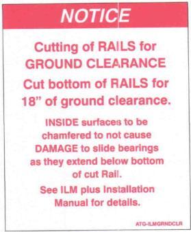
34 10.3 Column Modifications When columns are too long and exceed the 18 maximum ground clearance they will need to be cut. 1. Measure Height: With the liftgate in its highest position, measure from level ground to bottom of the column. Consider ride height at the vehicle s max load capacity, as well as dry unloaded ride height. 2. Mark Cut Line: Mark where the columns should be cut. Maximum ground clearance is Cut Column: Cut the excess length of the column. Important: Always deburr after cutting by grinding the inside and outside edges smooth. Chamfer the inside edge at 45 x1/8, Fig.14. If the columns are not deburred the slide pads will get damaged. 18" Maximum Ground Clearence Bottom View of Timmed Column Deburr edges from columns with a 45 x1/8 inner chamfer. Fig. 14 Revision
35 When diagonal supports are installed, raise the platform to stored position to avoid damaging the slide pads when welding. Add Diagonal Support (Optional): If desired, diagonal bracing can be connected to the rail and underside of the truck/trailer body for added strength or aesthetic purposes as shown below. Diagonal supports are not required. If desired cut an appropriate length of metal at 45 on both ends. If necessary, use ¼ thick plate to bridge the gap between two body sills. The Lifting bar from the liftgate s shipping stand can be cut and used for bracing. 3/16" Platform raised up to avoid welding on runner slide pads Diagonal Bracing on Street and Curb Side 18" Maximum Ground Clearence Revision
36 11 Holster and Cable Guard Installation Steps: Disconnect liftgate power cable at battery. Liftgate should be in stored position. 1. Holster Hole Mounting Pattern: Determine the bed height of the vehicle. Vehicles with bed height from 46 and above will mount on the lower mounting hole pattern, Fig. 14, of the liftgate column. Vehicles with bed heights from 46 and below will mount on the upper mounting hole pattern on the safety latch plate, Fig " and above Bedheight Vehicles Fig " and below Bedheight Vehicles Safety Latch Plate Upper Mounting Hole Pattern Lower Mounting Hole Pattern Curb Side Column Curb Side Column Fig Holster Installation: Lower Mounting Hole Pattern: Use four 3/16 x0.45 rivets to mount the holster to the curb side column, Fig. 16. Upper Mounting Hole Pattern: Use four 3/16 x0.87 to mount the holster to the curb side safety latch plate, Fig. 17. Hand Held Remote Holster Hand Held Remote Holster Fig. 17 3/16"x0.45" Rivets, 4X 3/16"x0.87" Rivets, 4X Fig. 16 Lower Mounting Hole Pattern Upper Mounting Hole Pattern Revision
37 3. Hand Held Remote: The liftgate will ship with a 2-button (standard), Fig. 18, or a 3-button (optional), Fig.19, hand held remote. Place the control inside the holster and align the mounting tab of the remote with the corresponding hole on the holster. Use the ¼ -20x0.50 self-tapping screw to secure the remote to the holster. Remote Mount Tab Remote Mount Tab 1/4"-20x0.50" Self Tapping Screw 1/4"-20x0.50" Self Tapping Screw Fig. 18 Fig Button Control Manual Close Hand Held Remote Wire Harness 3-Button Control Power Close Hand Held Remote Wire Harness 4. Wire Guard: Install the wire guard to hold the hand held remote wire harness secured to column. Fit the wire harness on the wire guard channel, make sure the harness is not pinched by the wire guard when place over the harness. Use three 3/16 x0.45 rivets to mount the wire guard to the liftgate column. Store excess harness away from sharp edges and moving parts. Wire Guard Hand Held Remote Harness 3/16"x0.45" Rivets, 3X 5. Operate: Connect power cable to the battery to briefly operate the liftgate functions with the remote. Revision
38 12 Final Installation Steps 1. Remove the Top Brace: Remove the top brace assembly by unbolting the two hex nuts. Discard the brace after removal, Fig Re-install Column Caps (if applicable): Columns caps should be installed when the columns have cooled from welding, Fig Re-install Wire Guard (if applicable): Reinstall the wire guard on the curb side column for Power Close units only, Fig. 22. Top Shipping Brace Hex Nut Fig. 20 2X Column Cap (If Applicable) Curb Side Column (Front View) Fig. 21 Power Close Hydraulic Hose Fig. 22 Revision
39 13 Electrical Installation Never secure cable in a way where it can make contact with other wiring, brake fuel, or air lines or get pinched against other objects. Check for 2 gauge grounding cable or heavier connecting vehicle batteries to chassis. If NOT supplied by the vehicle manufacture, one will need to be installed. Be sure to grind off paint or under coat and seal when installing a ground cable. Grind off paint before installing grounding cable 2 Gauge Min. Grounding Cable Chassis Frame Vehicle Batteries Battery to Chassis Frame Grounding If during installation the hydraulic power unit needs to be accessed, remove the four screws that secure the cover on the traverse. Cover Screws Revision
40 13.1 Cable Routing 1. The use of wire loom is highly recommended to protect and facilitate cable routing. Wire loom not supplied. 2. Route all cables along the wooden spacer and through the outside of the U-bolts or on the inside part of the channel. 3. Secure the wire along the wooded spacer with insulated cable clamps. Body Long Sill Wooden Spacer(s) Chassis Frame Cable Routed Outside of U-Bolts w/slack U-Bolt Cable Routed on Inside of Channel Insulated Cable Clamps Revision
41 13.2 Battery Wiring Overview *Resettable Circuit Breaker Single Pole Socket *Resettable Circuit Breaker *Resettable Circuit Breaker Auxiliary Batteries Ground Truck Batteries Ground 4GA. Liftgate Power Cable (+) 4GA. Liftgate Power Cable (+) Battery Wiring - Truck Battery Wiring - Single Pole - Trailer *Resettable Circuit Breaker (-) (+) Dual Pole Socket *Resettable Circuit Breaker Aux. Batteries Ground 4GA. Liftgate Power Cable (+) Battery Wiring - Dual Pole - Trailer *Resettable Circuit Breaker: 150 Amp Min. Replace with same amperage breaker when necessary. Ground: For optimal grounding, ground all batteries and power units to the body side rails of the vehicle. Revision
42 13.3 Powering the Liftgates and Circuit Breaker Installation Instructions below show how to install a circuit breaker at the truck batteries and adding power to the liftgate. Note: Circuit breakers are preinstalled inside the Battery Boxes (optional) from factory. 1. Attach the bus bar to the circuit breaker on the BAT post. Mount the circuit breaker securely to the positive terminal post of battery. 2. Connect the 4 gauge power cable from the liftgate or battery box to the AUX (auxiliary) post of the circuit breaker. 4 Gauge Power Cable from Liftgate/Battery Box AUX Post BAT Post Buss Bar To Positive (+) Battery Terminal 13.4 Toggle Switch Installation (Optional) 1. Install the toggle switch approximately 24 from the ground or at desired distance, Fig. 23. Use the hold pattern to mount the toggle switch to the inside of the vehicle body. Route the harness down to the pump and motor. Connected the toggle switch connectors to the prewired harness coming out from the bottom of the traverse, Fig. 24. Reference wiring diagram in Sections for wiring toggle switch. Curb Side Column Traverse Fig. 23 Mounting Hole Pattern ø7/8" Prewired Harness for Toggle Switch 1-3/4" Fig " Approx. Sill Traverse 7/8" 2X ø5/32" Curb Side Column Under Side View of Traverse Floor Revision
43 Button Hand Held Remote (Optional) 1. Mount the holster approximately from the floor or determine the best location as preferred by the end user, Fig Route the harness from the liftgate up through the inside corner post or between the wall extrusions of the vehicle. Use a wire clamp to secure the incoming harness, Fig Splice the cables from the liftgate to the hand held remote with butt connectors and seal each connection with heat shrink. 4. Reference Section for wiring remote. Corner Post Secure liftgate wire with wire clamp at entry point Floor Floor Sill Sill Fig. 25 Fig. 26 Revision
44 13.6 Rear Lights Mounting Dimensions Typical lights mounting dimensions for ILM+ liftgates. NOTE: Isuzu NPR style trucks. 38 to 42 bed heights. 16-3/4" 15" 22-3/4" Bumper Mount Location From Top of Bed Light Size 5-1/2"x13.2" 6" Clearance 40" ± 2" Bed Height Lights Mounted on Top of Bumper License Plate & Light Bracket Mounted to Face of Bumper 15-1/2" ± 2" Ground Clearance Revision
45 13.7 Electrical Schematic - Manual Closing Cab Switch Harness Power Load Ground Optional Cab Cut-Off Switch Seal with Heat Shrink Seal with Heat Shrink Lower Solenoid - Black Important Note: -All connectors are to be insulated and weather sealed. -In-Line ATC Fuse 15 Amp at solenoid. Replace with same amperage fuse when necessary. NOTICE: DO NOT attempt to jump in-line fuses with other objects other than the specified fuse(s). DO NOT increase the amperage rating of fuse. Serious harm to the liftgate will result when standard practices are not followed. 25 Ft. x 4 ga. Battery Cable Main Liftgate 2-Button Control Power - Red Lower - Black Remote Harness for Optional 2-Button Control or Toggle Switch Raise - Green Ground - Lower Solenoid - Black 150 amp Circuit Breaker 12V Power Supply Optional Inside Coil Cord Remote 2-Button Control P Optional Inside Hard Mount Toggle Switch Power - White #4 Lower - Black #6 Raise - Green #5 Power - #4 - Blue Lower - #6 - Yellow/Green Raise - #5 - Brown Lower Solenoid *A second valve applies to a power close units ILM Wiring Schematic - Manual Closing Piuma Ave. Cerritos, CA A Fuse Ground - Yellow/Green Power - Brown Load - Blue Starter - Green Power - Red Lower - Black Power - Black Ground - Yellow/Green GND Cab Shut Off Switch - Unplug Red (from Hand Held Control) and Black (from fuse) wires. - Connect Brown & Black wires. - Connect Blue & Red wires. Revision
46 13.8 Electrical Schematic - Power Closing Cab Switch Harness Power Load Ground Cab Cut-Off Switch Seal with Heat Shrink Ground - Yellow/Green Power - Brown Load - Blue Starter - Green Power - Red Close - White Lower - Black Seal with Heat Shrink Lower Solenoid - Black Lower Solenoid - Black Closing Solenoid Ground - Lower Solenoid - Black GND 5/16-18 UNC-2B 15A Fuse Power - Black Important Notes: -All connectors are to be insulated and weather sealed. -In-Line ATC Fuse 15 Amp at solenoid. Replace with same amperage fuse when necessary. NOTICE: DO NOT attempt to jump in-line fuses with other objects other than the specified fuse(s). DO NOT increase the amperage rating of fuse. Serious harm to the liftgate will result when standard practices are not followed. 25 Ft. x 4 ga. Battery Cable Main Liftgate 3-Button Control Optional Inside Coil Cord Remote 2-Button Control P Optional Inside Hard Mount Toggle Switch Power - White #4 Lower - Black #6 Raise - Green #5 Power - #4 - Blue Lower - #6 - Yellow/Green Raise - #5 - Brown Power - Red Lower - Black Remote Harness for Optional 2-Button Control or Toggle Switch Raise - Green Lower Solenoid Ground - Lower Solenoid - Black 150 amp Circuit Breaker 12V Power Supply ILM Wiring Schematic - Power Closing Piuma Ave. Cerritos, CA Revision
47 14 Hydraulics 14.1 Hydraulic Schematic - Manual Closing Lift Cylinder Cylinder Valve Body Locking Valve Main Cylinder Cap Port Port Pump Unit Port Flow Control Press-Comp 1.0 gpm Shuttle Valve Pump Relief Valve 2900 psi Filter Reservoir Tank ILM Wiring Schematic - Manual Closing Piuma Ave. Cerritos, CA Revision
48 14.2 Hydraulic Schematic - Power Closing Lift Cylinder Locking Valve Main Cylinder Cylinder Valve Body Locking Valve Closing Cylinder Port Flow Control Fixed #035 Closing Cylinder Port Pump Unit Port Flow Control Press-Comp 1.0 gpm Shuttle Valve Pump Relief Valve 2900 psi Filter Reservoir Tank ILM Wiring Schematic - Power Closing Piuma Ave. Cerritos, CA Revision
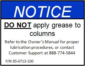
49 15 Lubrication When kept properly lubricated, the PALFINGER ILM liftgate will ensure long lasting usage. Therefore, the liftgate pivot points should be lubricated at the same time as the truck/trailer. Lubricate more frequently if the lift gate is heavily used or whenever the pivot points appear to be dry. Average ILM plus use is considered 15 cycles per day or 1200 cycles per quarter. DO NOT GREASE the Slider Bearings or Columns or Runners, as this will VOID your WARRANTY on the slide bearings. Column Lubrication: The columns are designed to run DRY and this is what Palfinger recommends first. However, in some wet or dirty environments, the columns may require periotic lubrication. The schedule will vary based on cycles, load, and environment. We recommend motor oil, 0W-20, 5W-30, or "bar & chain oil" administered via a machinist style oil can. Don't over do it, a little goes a long way, two or three squirts on to slide surfaces will last months in most cases, Fig. 27. Deck: There are 2 grease fittings to maintain, left and right main pivots, Fig. 27. Power Closing: There are 2 grease fittings to maintain, upper & lower cylinder pivot points. Manual Closing Gates: Use a light penetrating oil on closing aids; left & right side, upper & lower gas spring mounting points, Fig. 27. Deck support chains: Use a light penetrating oil on chain anchors; left & right side, Fig. 27. Lift roller chain: Under normal use and conditions, the lifting roller chain will require minimal lubrication or maintenance as it is impregnated with good quality grease and only makes contact with Polymer sprockets. In extreme wet or dirty environments, should roller chain show signs of drying or rust, lubricate with a good quality motor oil or chain oil listed above for columns, Fig. 27. Revision
50 Lubrication Locations: All bearing points must be lubricated in accordance with the maintenance interval. Oil: - Columns IN Hydraulic Oil: - Resevoir 1 Zerks: - 1 Platform 2 Zerks: - 1 Platform - 1 Cylinder Fig. 27 Grease fitting, 2 for deck, 2 for power closing. Hydraulic oil level in the power pack tank 2 to the top with deck on the ground. (see chart for recommended oils.) Deck support chains and optional Cart Stops (use light penetrating oil) IN Columns (optional) use motor oil or chain/bar oil. (Never use GREASE of any kind.) Revision
51 16 Cycle Test 16.1 Cycle Test and Bleed the Hydraulic System. Improper use of the liftgate may result in serious injury. DO NOT operate this liftgate without being properly instructed and fully understanding the Owner s manual. Platform may crush or pinch. Make certain area around liftgate is clear during all times of operation. No bleeding of hydraulic system is required. System is a self-bleeding system and is pre-bled from the factory. Test steps a minimum of five (5) times each to ensure NO unusual noises or movements are found. This will confirm all controls work correctly and hydraulic system is completely bled of air. Revision
52 MANUAL CLOSING Operating Instructions Steps: 1. Turn Power Switch On (If applicable): To activate power to the liftgate, turn the cab shutoff switch, Fig.28. Rocker Switch ON/OFF Switch Location for Trucks Fig Clear the platform sliding path by moving the storage safety latch manually. Hold the safetly latch down manually with one hand and press the Down button on the control with the other hand until the platform locking ears clear the safety latch, Fig. 29. Release the safety latch back to its original place. Platform Locking Ears Storage Safety Latch Storage Safety Latch Platform Locking Ears Storage Safety Latch Fig Open the platform manually, Fig. 30. Never stand directly under the platform. Press the Down button to lower the platform completely to the ground, Fig. 31. Fig. 31 Fig. 30 Revision
53 4. Center the load 24 from the front of the platform outward, Fig. 32. Use the Up button to raise the platform to bed level and the Down button to lower the platform down to ground level. Fig. 32 Load 24" Load Load 5. To store the platform, Press the Up bottom to raise the platform approximately 12 from the ground. Manually push the platform up parallel to the columns, Fig. 33. Press and hold the Up button to raise the platform until the platform locking ears are positioned in the locking plate and the storage safety lock is engaged. Fig. 33 Platform Locking Ears Storage Safety Latch 12" Revision
54 POWER CLOSING Operating Instructions Steps: 1. Turn Power Switch On (If applicable): To activate power to the liftgate, turn the cab shutoff switch, Fig.34. Rocker Switch ON/OFF Switch Location for Trucks Fig Clear the platform sliding path by moving the storage safety latch manually. Hold the safetly latch down manually with one hand and press the Down button on the control with the other hand until the platform locking ears clear the storage safety latch, Fig. 35. Release the safety latch back to its original place. Platform Locking Ears Storage Safety Latch Storage Safety Latch Platform Locking Ears Storage Safety Latch Fig Open the platform by pressing and holding the Shift and Down buttons simultaneously, Fig. 36. Never stand directly under the platform. Press and hold the Down button to lower the platform completely to the ground, Fig. 37. Fig. 37 Fig. 36 Revision
55 4. Center the load 24 from the front of the platform outward, Fig. 38. Use the Up button to raise the platform to bed level and the Down button to lower the platform down to ground. Fig " Load Load Load 5. To store the platform, Press the Up button to raise the platform approximately 12 from the ground. Press and hold the Shift and Up buttons simultaneously until the platform is parallel to the columns, Fig. 39. Press the Up button to raise the platform until the platform locking ears are positioned in the locking plate and the storage safety lock is engaged. Platform Locking Ears Storage Safety Latch 12" Fig. 39 Revision
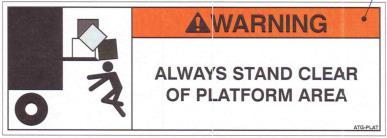
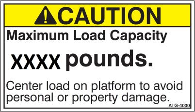
56 17 Decal Placement and Inspection For operator s safety, all decals appearing in Decal Kit must be placed visibly on control side of liftgate to be read by operator. This is typically a combination of decals on the liftgate and vehicle body. Please make sure to place the maximum capacity decal (C) on driver and curb side. Decal Kit Decal Qty. Part No. Description A 1 ATG-OPERILM-MC Operating Instructions Manual Close AA 1 ATG-OPERILM-PC Operating Instructions Power Close B 1 ATG-SWILM-MC Main Operating Switch Manual Close BB 1 ATG-SWILM-PC Main Operating Switch Power Close C 2 ATG-XXXX Max. Capacity D 1 ATG-URGWA Urgent warning: Elevating gate instructions E 2 ATG-WLH Warning: Liftgate can crush F 2 ATG-PLAT Warning: Always stand clear of platform area G 1 ATG-RESET Circuit Breaker Protection. H 1 ATG-BKR Circuit Breaker Reset (must be located at the circuit breaker) I 1 ATG-ILMSTORAGE Notice: Storage Latch J 2 ATG-ILMGRNCLR Notice: Ground Clearance K Do Not Grease Columns L 1 ATG-CAB Liftgate Shut-Off (Place next to the Shut-Off switch, if applicable) M 1 ATG-UD Toggle Switch Decal, Up-Down (if applicable) N Roll Conspicuity Tape (if applicable) It is the installer s responsibility to determine the proper application of the Conspicuity tape, and to ensure that the vehicle or trailer meets DOT and federal lighting regulations. The following diagram is a guideline for placement on trailers over 80 wide and GVWR of 10,000 lbs. or more. This document is not intended to replace published agency regulations, and it is strongly recommended that the installer refer to the Code of Federal Regulations (CFR) which can be viewed at Revision


57 Decal - C Decal B Decal BB Decal A Decal AA Decal - G Decal - F Decal - E Decal - I Decal - K Decal - D Decal - H Decal - N Decal - M Decal - J Decal - L K C F E J K I D A or AA B or BB C G E F J Revision
58 18 Final Inspection Check List Liftgate failure or malfunction could result in property damage, personal injury or death if you fail to check each of the following items listed. DO NOT USE the liftgate if any of the following points are NOT verified and checked. Installation is NOT complete and all WARRANTIES are VOID if you have not checked and verified all items listed on this inspection sheet. Inspection sheet is to be filed at the facility where liftgate was installed. Structural Inspection Lifting bar and shipping feet are removed from the liftgate. All welds are 100% complete per this manual. All nuts, bolts, mounting hardware, pins, chain anchors are tight. All mounting dimensions are correct and liftgate is square and parallel per this manual. Hydraulic Inspection Pump reservoir is filled to 1" from top when platform is opened and on the ground. Hydraulic components and connections do not leak. (Should be checked after unit is hydraulically locked for five (5) minutes.) All hydraulic lines are secured with cable ties, hoses clamps, or other fasteners. Electrical Inspection Battery cable(s) attached and clamped tight and dielectric grease is used to seal all connections. All electrical lines are secured with cable ties, hoses clamps, or other fasteners and are away from sharp edges and moving parts. Circuit Breakers installed and wired per instructions. Lights wired properly and operate per DOT, State, and Federal requirements. Measure battery voltages: Flooded Batteries = 12.6V, AGM Batteries = 12.8V. Operational Inspection All decals are in place and legible per instructions. All pivot points are lubricated per instructions. Platform secures properly in its stowed position latches. Platform powers UP and locks hydraulically in latches. Platform travels up and down smoothly and freely, without any hesitation or unusual noises. Platform is level with the floor of the vehicle when raised completely. Platform rests on the ground evenly when lowered completely. Platform opens and closes properly at correct speed (2 to 4 inches per second) and makes contact with pads in quiet manner. The liftgate serial number and model number are documented on the inside of the front cover of the Owners Manual in the space provided. Owners Manual is in the vehicle's glove box. Supervisor has demonstrated the instructions in the Owners Manual to the customer/driver upon delivery. Gate is properly lubricated as explained in Section 15. Inspection Information (Please Print): Name: Signature: Completed by: Title: Date: Liftgate Model: Liftgate Serial Number: Revision
59 Revision
ILM16 ILM20 ILM30 ILM12AF ILM16AF ILM20AF ILM30AF
 ILM Series Liftgates Read Before Installing INSTALLATION MANUAL For Models: ILM12 ILM16 ILM20 ILM30 ILM12AF ILM16AF ILM20AF ILM30AF Interlift, Inc. a Subsidary of MBB Liftsystems AG 15939 Pluma Avenue
ILM OWNER S MANUAL. ECN-M096 Rev. 1.6, Date Part #
 ILM OWNER S MANUAL ECN-M096 Rev. 1.6, Date 08-29-2013 Part #90-0709-100 PALFINGER Liftgates, LLC. 15939 Piuma Ave., Cerritos, CA 90703 Tel (888)-774-5844 Fax (562)-924-8318 PALFINGER Liftgates, LLC. 572
INSTALLATION MANUAL & CHECK OFF SHEET
 INSTALLATION MANUAL & CHECK OFF SHEET ILT 35, 3500 lbs. Capacity ILT 40, 4000 lbs. Capacity 03/15 ILT 35/40, ILT-PD 35/40, ILT-WR 35/40 Installation Manual Document Part Number: ML90-1013-000 ECN-M0549,
ILR INSTALLATION MANUAL & CHECK-OFF SHEET. ECN-M0246 Rev. 1.6, Date Part #
 ILR INSTALLATION MANUAL & CHECK-OFF SHEET ECN-M0246 Rev. 1.6, Date 07-03-2013 Part #90-0313-200 PALFINGER Liftgates, LLC. 15939 Piuma Ave., Cerritos, CA 90703 Tel (888)-774-5844 Fax (562)-924-8318 PALFINGER
ILU INSTALLATION MANUAL & CHECK-OFF SHEET. ECN-M0257 Rev. 1.5, Date Part #
 ILU INSTALLATION MANUAL & CHECK-OFF SHEET ECN-M0257 Rev. 1.5, Date 07-15-2013 Part #90-1313-200 PALFINGER Liftgates, LLC. 15939 Piuma Ave., Cerritos, CA 90703 Tel (888)-774-5844 Fax (562)-924-8318 PALFINGER
INSTALLATION MANUAL & CHECK OFF SHEET
 INSTALLATION MANUAL & CHECK OFF SHEET ILT 35, 3500 lbs. Capacity ILT 40, 4000 lbs. Capacity 07/16 ILT 35/40, ILT-PD 35/40, ILT-WR 35/40, ILT-WR-PD 35/40 Owner s Manual Document Part Number: 90-1013-000
INSTALLATION MANUAL & CHECK OFF SHEET
 INSTALLATION MANUAL & CHECK OFF SHEET PLR 20S, 2000 lbs. Capacity PLR 25S, 2500 lbs. Capacity PLR 25D, 2500 lbs. Capacity PLR 33D, 3300 lbs. Capacity 06/17 PLR 20S/25S/25D/33D Document Part Number: 90-0316-000
INSTALLATION MANUAL & CHECK OFF SHEET
 INSTALLATION MANUAL & CHECK OFF SHEET ILP 25, 2500 lbs. Capacity ILP 33, 3300 lbs. Capacity 08/16 ILP 25/33 Document Part Number: 90-0116-000 / 16-684_90-00_00-00 ECN-M0829, Rev. 1.2, 08-01-16 Copyright
ILUK INSTALLATION MANUAL & CHECK-OFF SHEET. ECN-M0256 Rev. 1.5, Date Part #
 ILUK INSTALLATION MANUAL & CHECK-OFF SHEET ECN-M0256 Rev. 1.5, Date 07-11-2013 Part #90-0513-200 PALFINGER Liftgates, LLC. 15939 Piuma Ave., Cerritos, CA 90703 Tel (888)-774-5844 Fax (562)-924-8318 PALFINGER
ILF 44/55 INSTALLATION MANUAL & CHECK-OFF SHEET. ECN-M0253 Rev. 1.4, Date Part #
 ILF 44/55 INSTALLATION MANUAL & CHECK-OFF SHEET ECN-M0253 Rev. 1.4, Date 07-10-2013 Part #90-0813-200 PALFINGER Liftgates, LLC. 15939 Piuma Ave., Cerritos, CA 90703 Tel (888)-774-5844 Fax (562)-924-8318
MiniFix INSTALLATION MANUAL & CHECK-OFF SHEET. ECN-M0262 Rev. 1.3, Date Part #
 MiniFix INSTALLATION MANUAL & CHECK-OFF SHEET ECN-M0262 Rev. 1.3, Date 07-15-2013 Part #90-0913-200 PALFINGER Liftgates, LLC. 15939 Piuma Ave., Cerritos, CA 90703 Tel (888)-774-5844 Fax (562)-924-8318
ILT / ILT-WR / ILT-PD INSTALLATION MANUAL & CHECK-OFF SHEET
 ILT / ILT-WR / ILT-PD INSTALLATION MANUAL & CHECK-OFF SHEET ECN-M0275 Rev. 1.11, Date 08-01-2013. Part #90-1013-000 PALFINGER Liftgates, LLC. 15939 Piuma Ave., Cerritos, CA 90703 Tel (888)-774-5844 Fax
ILUK INSTALLATION MANUAL & CHECK-OFF SHEET Rev. 1.4, Date
 ILUK INSTALLATION MANUAL & CHECK-OFF SHEET Rev. 1.4, Date 8-11-2011 INTERLIFT, INC. dba MBB Palfinger 15939 Piuma Ave., Cerritos, CA 90703 Tel (888)-774-5844 Fax (562)-924-8318 572 Whitehead Road, Trenton,
PARTS MANUAL. ILD+ 33, 3300 lbs. Capacity ILD+ 44, 4400 lbs. Capacity ILD+ 55, 5500 lbs. Capacity ILD+ 66, 6600 lbs.
 PARTS MANUAL ILD+ 33, 3300 lbs. Capacity ILD+ 44, 4400 lbs. Capacity ILD+ 55, 5500 lbs. Capacity ILD+ 66, 6600 lbs. Capacity 12/16 Document Part Number: 90-1114-000 / 14-680_90-00_00-00 ECN-M0913, Rev.
ILK INSTALLATION MANUAL & CHECK-OFF SHEET. ECN-M0254 Rev. 1.4, Date Part #
 ILK INSTALLATION MANUAL & CHECK-OFF SHEET ECN-M0254 Rev. 1.4, Date 07-10-2013 Part #90-0413-200 PALFINGER Liftgates, LLC. 15939 Piuma Ave., Cerritos, CA 90703 Tel (888)-774-5844 Fax (562)-924-8318 PALFINGER
Column gate. Interlift Inc. a member of MBB Palfinger
 ILM plus Column gate PARTS BREAK DOWN Interlift Inc. a member of MBB Palfinger 599 Piuma Ave, Cerritos, CA 9070 TEL. (888)-774-5844 FAX. (56)-94-88 57 Whitehead Road, Trenton, NJ 0869 TEL.(609)-587-400
INSTALLATION MANUAL & CHECK OFF SHEET
 INSTALLATION MANUAL & CHECK OFF SHEET Minifix, 1100 lbs. Capacity Minifix, 1320 lbs. Capacity 09/15 Minifix Installation Manual Document Part Number: 90-0913-200 ECN-M0581, Rev. 1.4, 09-11-15 Copyright
INTERLIFT. ILK INSTALLATION MANUAL & CHECK-OFF SHEET Rev. 1.2, Date
 INTERLIFT ILK INSTALLATION MANUAL & CHECK-OFF SHEET Rev. 1.2, Date 09-14-2011 Interlift, Inc. dba MBB Palfinger. 15939 Piuma Ave., Cerritos, CA 90703 Tel (888)-774-5844 Fax (562)-924-8318 572 Whitehead
PARTS MANUAL. ILK 18, 1800 lbs. Capacity 05/17
 PARTS MANUAL ILK 18, 1800 lbs. Capacity 05/17 Document Part Number: 90-0417-000 / 17-68_90-00_00-00 ECN-M0968, Rev. 1.0, 05-19-17 Copyright 017 Palfinger Liftgates LLC. All rights reserved. Information
PARTS MANUAL. ECN-M0XXX Rev. 2.0, Date Part #
 ILM plus,0,,0 PARTS MANUAL ECN-M0XXX Rev..0, Date 0--0 Part #90-07-000 99 Piuma Ave., Cerritos, CA 9070 Tel (888)-77-8 Fax ()-9-88 7 Whitehead Road, Trenton, NJ 089 Tel (09)-87-00 Fax (09)-87-0 Visit our
INTERLIFT. ILF INSTALLATION MANUAL & CHECK-OFF SHEET Rev. 1.2, Date
 INTERLIFT ILF INSTALLATION MANUAL & CHECK-OFF SHEET Rev. 1.2, Date 08-04-2011 INTERLIFT, INC. a member of MBB 15939 Piuma Ave., Cerritos, CA 90703 Tel (888)-774-5844 Fax (562) 924-8318 Visit our website
Installation Manual. LHS & LLBS Hide-A-Way Tuckunder Style
 Installation Manual LHS & LLBS Hide-A-Way Tuckunder Style 10900 Kenwood Road Cincinnati, OH 45242 Ph: 513-891-6210 Toll-Free: 866-539-6261 Fax: 513-891-4901 www.leymanlift.com sales@leymanlift.com LML00136-5/1/15
PARTS MANUAL. PLR 20S, 2000 lbs. Capacity PLR 25S, 2500 lbs. Capacity PLR 25D, 2500 lbs. Capacity PLR 33D, 3300 lbs.
 PARTS MANUAL PLR 20S, 2000 lbs. Capacity PLR 25S, 2500 lbs. Capacity PLR 25D, 2500 lbs. Capacity PLR 33D, 3300 lbs. Capacity 08/16 Document Part Number: 90-0316-004 / 16-695_90-00_00-04 ECN-M0863, Rev.
Installation Manual WDV & WDVBG lb. Capacity Rail Liftgates
 www.waltco.com Phone: 800.411.5685 parts@waltco.com Fax: 800.411.5684 Installation Manual WDV & WDVBG 3500-6600 lb. Capacity Rail Liftgates Last Change: Date Page(s) Description 04/2017 11,19,29,30,44
Installation Manual MDL, DS, DT, SB
 www.waltco.com Phone: 800.411.5685 parts@waltco.com Fax: 800.411.5684 Installation Manual MDL, DS, DT, SB 1250 lb. - 3000 lb. Capacity Rail Liftgates Last Change Date Page(s) Description 9-2013 14, 15,
Installation Manual MDL, DS, DT, SB
 www.waltco.com Phone: 800.411.5685 parts@waltco.com Fax: 800.411.5684 Installation Manual MDL, DS, DT, SB 1250 lb. - 3000 lb. Capacity Rail Liftgates GR02909 Waltco Lift Corp. Waltco Lift Corp. Waltco
ILK OWNER S MANUAL. ECN-M0605 Rev. 1.4, Date Part #
 ILK OWNER S MANUAL ECN-M0605 Rev. 1.4, Date 06-11-15 Part #90-0413-100 PALFINGER Liftgates, LLC. 15939 Piuma Ave., Cerritos, CA 90703 Tel (888)-774-5844 Fax (562)-924-8318 PALFINGER Liftgates, LLC. 572
ILK-18 INSTALLATION MANUAL & CHECK-OFF SHEET. ECN-M0578 Rev. 1.0, Date Part #
 ILK-18 INSTALLATION MANUAL & CHECK-OFF SHEET ECN-M0578 Rev. 1.0, Date 04-06-15 Part #90-0415-000 PALFINGER Liftgates, LLC. 15939 Piuma Ave., Cerritos, CA 90703 Tel (888)-774-5844 Fax (562)-924-8318 PALFINGER
Railgates By THIEMAN VL-30, 40, 50 PLEASE READ AND UNDERSTAND THE CONTENTS OF THIS MANUAL BEFORE OPERATING THE EQUIPMENT. HIEMAN
 VL SERIES Railgates By THIEMAN VL-30, 40, 50 INSTALLATION INSTRUCTIONS! IMPORTANT! KEEP IN VEHICLE! PLEASE READ AND UNDERSTAND THE CONTENTS OF THIS MANUAL BEFORE OPERATING THE EQUIPMENT. NATIONAL TRUCK
M REV. B AUGUST 2010 INSTALLATION MANUAL GPTWR-3
 M-08-36 REV. B AUGUST 2010 INSTALLATION MANUAL GPTWR-3 MAXON Lift Corp. 2010 TABLE OF CONTENTS WARNINGS... 3 SAFETY INSTRUCTIONS... 3 STANDARD LIFTGATE COMPONENTS... 4 GPTWR-3 INSTALLATION PARTS BAGS...
LIFT CORP. CUSTOMER SERVICE: (562) (800) FAX: (888) Slauson Ave. Santa Fe Springs, CA TECHNICAL SERVICE: (800)
 (800) FAX: (888) Slauson Ave. Santa Fe Springs, CA TECHNICAL SERVICE: (800)") M-90-1 REV. B JAN. 2000 INSTALLATION MANUAL RC-2B RC-3B RC-4B RC-5B RC-6B RC-6K 11921 Slauson Avenue. Santa Fe Springs, CA. 90670 (800) 227-4116 C MAXON Lift Corp. 1999 LIFT CORP. CUSTOMER SERVICE: (562)
M-90-1 REV. B JAN. 2000 INSTALLATION MANUAL RC-2B RC-3B RC-4B RC-5B RC-6B RC-6K 11921 Slauson Avenue. Santa Fe Springs, CA. 90670 (800) 227-4116 C MAXON Lift Corp. 1999 LIFT CORP. CUSTOMER SERVICE: (562)
INSTALLATION MANUAL DMD-22 & DMD-33
 M-12-20 REV. E JULY 2016 INSTALLATION MANUAL DMD-22 & DMD-33 To fi nd maintenance & parts information for your DMD Liftgate, go to www.maxonlift. com. Click the PRODUCTS, RAILIFT & DMD buttons. Open the
Installation Manual WDV & WDVBG
 www.waltco.com Phone: 800.411.5685 parts@waltco.com Fax: 800.411.5684 Installation Manual WDV & WDVBG 3500-6600 lb. Capacity Rail Liftgates Last Change: Date Page(s) Description 2-2015 34 46 Updated hydraulic
TT-12 OWNERS MANUAL/PARTS LIST
 TOPLIFTER Tailgates By THIEMAN TT-12 OWNERS MANUAL/PARTS LIST SHOWN WITH OPTIONAL 2 PC. ALUMINUM PLATFORM! IMPORTANT! KEEP IN VEHICLE! PLEASE READ AND UNDERSTAND THE CONTENTS OF THIS MANUAL BEFORE OPERATING
TT-15 INSTALLATION INSTRUCTIONS SHOWN WITH OPTIONAL 2 PC. ALUMINUM PLATFORM AND LIGHT KIT
 TM TOPLIFTER Tailgates By THIEMAN TT-15 INSTALLATION INSTRUCTIONS SHOWN WITH OPTIONAL 2 PC. ALUMINUM PLATFORM AND LIGHT KIT! IMPORTANT! KEEP IN VEHICLE! PLEASE READ AND UNDERSTAND THE CONTENTS OF THIS
INSTRUCTIONS, (FORD) SUPER DUTY INSTALLATION KIT (C2 PICKUP LIFTGATES)
 SUPER DUTY INSTALLATION KIT (C2 PICKUP LIFTGATES)") LIFT CORPORATION Sht. 1 of 22 DSG# M-16-32 Rev. - Date: 12/13/16 INSTRUCTIONS, (FORD) SUPER DUTY INSTALLATION KIT (C2 PICKUP LIFTGATES) FORD SUPER DUTY F-250, F-350 & F-450 PICKUP TRUCKS, 2017 MODEL KIT
LIFT CORPORATION Sht. 1 of 22 DSG# M-16-32 Rev. - Date: 12/13/16 INSTRUCTIONS, (FORD) SUPER DUTY INSTALLATION KIT (C2 PICKUP LIFTGATES) FORD SUPER DUTY F-250, F-350 & F-450 PICKUP TRUCKS, 2017 MODEL KIT
INSTALLATION INSTRUCTIONS
 TM WEIGHTLIFTER Tailgates By THIEMAN TWL 125, 16, 20 INSTALLATION INSTRUCTIONS! IMPORTANT! KEEP IN VEHICLE! PLEASE READ AND UNDERSTAND THE CONTENTS OF THIS MANUAL BEFORE OPERATING THE EQUIPMENT. NTEA T
GT- 33/44 WARNING. Installation Instructions 4400 lb. Capacity Sliding Liftgate. Visit us at
 GT- 33/44 Visit us at www.waltco.com Installation Instructions 4400 lb. Capacity Sliding Liftgate WARNING Improper installation of this liftgate could result in severe personal injury or death. Read and
ILUK OWNER S MANUAL. ECN-M0256 Rev. 1.4, Date Part #
 ILUK OWNER S MANUAL ECN-M0256 Rev. 1.4, Date 07-11-2013 Part #90-0513-100 PALFINGER Liftgates, LLC. 15939 Piuma Ave., Cerritos, CA 90703 Tel (888)-774-5844 Fax (562)-924-8318 PALFINGER Liftgates, LLC.
650 Series Cargo Van Lift Mounting Instructions Ford Transit (Standard Roof) 2015-Present
 2015-Present") TOMMY GATE OWNER'S / OPERATOR'S MANUAL 650 Series 650 LB Capacity 650 Series Cargo Van Lift Mounting Instructions Ford Transit (Standard Roof) 2015-Present Installing the Base Plate 1. Examine the interior
TOMMY GATE OWNER'S / OPERATOR'S MANUAL 650 Series 650 LB Capacity 650 Series Cargo Van Lift Mounting Instructions Ford Transit (Standard Roof) 2015-Present Installing the Base Plate 1. Examine the interior
Installation Manual BZ-33, BZ-44 Gen 5
 www.waltco.com Phone: 800.411.5685 parts@waltco.com Fax: 800.411.5684 Installation Manual BZ-33, BZ-44 Gen 5 3300 lb. & 4400 lb. Capacity Cantilever Liftgates GR02912 Waltco Lift Corp. Waltco Lift Corp.
ILK OWNER S MANUAL. ECN-M0254 Rev. 1.3, Date Part #
 ILK OWNER S MANUAL ECN-M0254 Rev. 1.3, Date 07-10-2013 Part #90-0413-100 PALFINGER Liftgates, LLC. 15939 Piuma Ave., Cerritos, CA 90703 Tel (888)-774-5844 Fax (562)-924-8318 PALFINGER Liftgates, LLC. 572
M APRIL 2012 INSTALLATION MANUAL DMD-22 & DMD-33
 M-11-13 APRIL 2012 INSTALLATION MANUAL DMD-22 & DMD-33 MAXON Lift Corp. 2012 TABLE OF CONTENTS WARNINGS... 3 NOTICE... 4 VEHICLE REQUIREMENTS... 5 BODY STRENGTH... 5 INSTALLED LIFTGATE... 7 LIFTGATE INSTALLATION
Installation Manual. LHLP4500G Hide-A-Way Tuckunder Style
 Installation Manual LHLP4500G Hide-A-Way Tuckunder Style LEYMAN MANUFACTURING CORPORATION 10900 Kenwood Road Cincinnati, OH 45242 1-866-LEYMAN-1 1-866-539-6261 513-891-6210 Fax 513-891-4761 www.leymanlift.com
ILD PLUS 33, 44, 55, 66
 ILD PLUS 33,,, PARTS MANUAL ECN-M0XXX Rev. 1., Date 0--201 Part #0-1-000 13 Piuma Ave., Cerritos, CA 0703 Tel ()-77- Fax (2)--31 72 Whitehead Road, Trenton, NJ 01 Tel (0)-7-200 Fax (0)-7-201 Visit our
INSTRUCTIONS, (FORD) SUPER DUTY INSTALLATION KIT (C2 PICKUP LIFTGATES)
 SUPER DUTY INSTALLATION KIT (C2 PICKUP LIFTGATES)") LIFT CORPORATION Sht. 1 of 20 DSG# M-14-32 Rev. B Date: 05/31/2017 INSTRUCTIONS, (FORD) SUPER DUTY INSTALLATION KIT (C2 PICKUP LIFTGATES) FORD SUPER DUTY F-250 PICKUP TRUCKS, 1999-2016 FORD SUPER DUTY
LIFT CORPORATION Sht. 1 of 20 DSG# M-14-32 Rev. B Date: 05/31/2017 INSTRUCTIONS, (FORD) SUPER DUTY INSTALLATION KIT (C2 PICKUP LIFTGATES) FORD SUPER DUTY F-250 PICKUP TRUCKS, 1999-2016 FORD SUPER DUTY
M JULY 2017 GPTLR Liftgate www. maxonlift.com PRODUCTS, TUK-A-WAY GPTLR Maintenance Manual PRODUCT DOCUMENTATION PARTS PORTAL TUK-A-WAY GPTLR
 M-16-24 JULY 2017 To find maintenance information for your GPTLR Liftgate, go to www. maxonlift.com. Click the PRODUCTS, TUK-A-WAY & GPTLR buttons. Open the Maintenance Manual in the PRODUCT DOCUMENTATION
TE-20 & INSTALLATION MANUAL M REV. F SEPTEMBER 2015
 M-12-04 REV. F SEPTEMBER 2015 INSTALLATION MANUAL TE-20 & 72-150 To find maintenance & parts information for your TE-20 & 72-150 Liftgate, go to www.maxonlift.com. Click the PRODUCTS, TUK-A-WAY and TE-20
Tailgates By THIEMAN M16, 20, 25, 30 MLB16, 20, 25, 30 INSTALLATION INSTRUCTIONS
 STOWAWAY Tailgates By THIEMAN M16, 20, 25, 30 MLB16, 20, 25, 30 INSTALLATION INSTRUCTIONS M-25 shown! IMPORTANT! KEEP IN VEHICLE! PLEASE READ AND UNDERSTAND THE CONTENTS OF THIS MANUAL BEFORE OPERATING
INSTRUCTION, DODGE TRUCKS INSTALLATION KIT (C2 LIFTGATES)
") LIFT CORPORATION Sht. 1 of 23 DSG# M-14-25 Rev. B Date: 05/16/17 INSTRUCTION, DODGE TRUCKS INSTALLATION KIT (C2 LIFTGATES) DODGE 1500 PICKUPS, 2002 TO 2016 DODGE 2500 PICKUPS, 2003 TO 2016 KIT P/N 289492-01
LIFT CORPORATION Sht. 1 of 23 DSG# M-14-25 Rev. B Date: 05/16/17 INSTRUCTION, DODGE TRUCKS INSTALLATION KIT (C2 LIFTGATES) DODGE 1500 PICKUPS, 2002 TO 2016 DODGE 2500 PICKUPS, 2003 TO 2016 KIT P/N 289492-01
ILR 20,25,30 PARTS MANUAL. ECN-M0XXX Rev. 2.2, Date Part #
 ILR 0,,0 PARTS MANUAL ECN-M0XXX Rev.., Date 04--04 Part #90-04-000 99 Piuma Ave., Cerritos, CA 900 Tel ()-4-44 Fax (6)-94- Whitehead Road, Trenton, NJ 069 Tel (609)--400 Fax (609)--40 Visit our website
INSTALLATION MANUAL RA-35 & RA-45 M REV. D SEPTEMBER 2017
 M-13-01 REV. D SEPTEMBER 2017 INSTALLATION MANUAL RA-35 & RA-45 To fi nd maintenance and parts information for your RA Liftgate, go to www.maxonlift.com. Click the PRODUCTS, SLIDELIFT & RA buttons. Open
INSTRUCTIONS, NISSAN TITAN TRUCK INSTALLATION KIT (C2 PICKUP LIFTGATES)
") LIFT CORPORATION Sht. 1 of 18 DSG# M-14-33 Rev. A Date: 05/31/2017 INSTRUCTIONS, NISSAN TITAN TRUCK INSTALLATION KIT (C2 PICKUP LIFTGATES) NISSAN TITAN PICKUP TRUCKS, 2004-2015 KIT P/N 295040-01 MOUNTING
LIFT CORPORATION Sht. 1 of 18 DSG# M-14-33 Rev. A Date: 05/31/2017 INSTRUCTIONS, NISSAN TITAN TRUCK INSTALLATION KIT (C2 PICKUP LIFTGATES) NISSAN TITAN PICKUP TRUCKS, 2004-2015 KIT P/N 295040-01 MOUNTING
Installation Manual C15, C20, C25
 www.waltco.com Phone: 800.411.5685 parts@waltco.com Fax: 800.411.5684 Installation Manual C15, C20, C25 1600, 2000, 2500 lb. Capacity Flipaway Liftgates Waltco Lift Corp. Waltco Lift Corp. Waltco Lift
Parts Manual EM and EMTC 2500 lb. and 3300 lb. Capacity Flipaway Liftgates
 www.waltco.com Phone: 800.4.5685 parts@waltco.com Fax: 800.4.5684 Parts Manual EM and EMTC 2500 lb. and 3300 lb. Capacity Flipaway Liftgates This manual identifies parts for Liftgates manufactured: /200
INSTRUCTIONS, RAM DUAL REAR WHEEL TRUCKS INSTALLATION KIT (C2 LIFTGATES)
") LIFT CORPORATION Sht. 1 of 23 DSG# M-15-25 Rev. B Date: 05/31/2017 INSTRUCTIONS, RAM DUAL REAR WHEEL TRUCKS INSTALLATION KIT (C2 LIFTGATES) RAM 3500 DUAL REAR WHEEL PICKUP TRUCKS, 2013 TO 2015 KIT P/N
LIFT CORPORATION Sht. 1 of 23 DSG# M-15-25 Rev. B Date: 05/31/2017 INSTRUCTIONS, RAM DUAL REAR WHEEL TRUCKS INSTALLATION KIT (C2 LIFTGATES) RAM 3500 DUAL REAR WHEEL PICKUP TRUCKS, 2013 TO 2015 KIT P/N
M REV. D APRIL 2008 INSTALLATION MANUAL GPTLR-25, GPTLR-33, GPTLR-44, & GPTLR-55
 M-04-06 REV. D APRIL 2008 INSTALLATION MANUAL GPTLR-25, GPTLR-33, GPTLR-44, & GPTLR-55 MAXON Lift Corp. 2008 TABLE OF CONTENTS GPTLR LIFTGATE COMPONENTS... 5 GPTLR-SERIES INSTALLATION PARTS BOX... 6 VEHICLE
Parts Manual HLF 2500, 3000, 4000 & 5000 lb. Capacity Flipaway Liftgates
 www.waltco.com Phone: 800.4.5685 parts@waltco.com Fax: 800.4.5684 Parts Manual HLF 500, 3000, 4000 & 5000 lb. Capacity Flipaway Liftgates EO:7 Rev 7 This manual identifies parts for Liftgates manufactured:
Installation Manual HLF-25, 30, 40, & , 3000, 4000, & 5000 lb. Capacity Flipaway Liftgates
 www.waltco.com Phone: 800.411.5685 parts@waltco.com Fax: 800.411.5684 Installation Manual HLF-25, 30, 40, & 50 2500, 3000, 4000, & 5000 lb. Capacity Flipaway Liftgates Last Change Date Page(s) Description
Owner s Manual PTN 1250 lb. and 1600 lb. Capacity Rail Liftgate
 www.waltco.com Phone: 800.211.3074 sales@waltco.com Fax: 800.211.3075 Owner s Manual PTN 1250 lb. and 1600 lb. Capacity Rail Liftgate Last Change GR02910 Date Page(s) Description 3-2017 10, 14, 18 P10
M REV B SEPTEMBER 2017
 M-16-33 REV B SEPTEMBER 2017 To fi nd maintenance & parts information for your TE-25 or TE-30 Liftgate, go to www. maxonlift.com. Click the PRODUCTS, TUK-A-WAY and TE-25/TE-30 buttons. Open the Maintenance
Table of Contents General Information Safety Message Classifi cation...2 Safety Notes...3 Terminology...4 Coupler Lifting Lug...
 Table of Contents General Information Safety Message Classifi cation...2 Safety Notes...3 Terminology...4 Coupler Lifting Lug...6 Assembly and Installation General Information...7 How it works...7 Component
INSTALLATION INSTRUCTIONS
 INSTALLATION INSTRUCTIONS Thank you for purchasing ROLTECTM Electric Hopper Conversion. Agri-Cover, Inc. proudly manufactured this hardware using superior quality materials and workmanship. With proper
Tailgates By THIEMAN WT20, 30 & 40 PLEASE READ AND UNDERSTAND THE CONTENTS OF THIS MANUAL BEFORE OPERATING THE EQUIPMENT. HIEMAN
 WEIGHTLIFTER Tailgates By THIEMAN WT20, 30 & 40 OWNERS MANUAL/PARTS LIST! IMPORTANT! KEEP IN VEHICLE! PLEASE READ AND UNDERSTAND THE CONTENTS OF THIS MANUAL BEFORE OPERATING THE EQUIPMENT. NATIONAL TRUCK
RCM-1250 C RCM-1250 C AB RCM-1600 RCM-1600 C AB
 M-91-17 REV. E AUGUST 2012 INSTALLATION MANUAL RCM-1250 C RCM-1250 C AB RCM-1600 RCM-1600 C AB LIFT CORP. 11921 Slauson Avenue Santa Fe Springs, CA 90607 (800) 227-4116 MAXON Lift Corp. 2012 TABLE OF CONTENTS
Installation Manual C15, C20, C , 2000, 2500 lb. Capacity Flipaway Liftgates
 www.waltco.com Phone: 800.411.5685 parts@waltco.com Fax: 800.411.5684 Installation Manual C15, C20, C25 1600, 2000, 2500 lb. Capacity Flipaway Liftgates Last Change: Date Pages Description 4-2016 8, 19,
INTERLIFT. ILP & ILFS INSTALLATION MANUAL & CHECK-OFF SHEET INTERLIFT, INC. a member of MBB
 INTERLIFT ILP & ILFS INSTALLATION MANUAL & CHECK-OFF SHEET INTERLIFT, INC. a member of MBB 15939 Piuma Ave., Cerritos, CA 90703 Tel (562) 924-8218 Fax (562) 924-8318 Visit out website at www.interlift.net
INSTALLATION INSTRUCTIONS
 INSTALLATION INSTRUCTIONS WARNING: NEVER EXCEED YOUR VEHICLE MANUFACTURER'S RECOMMENDED TOWING CAPACITY A20 5TH WHEEL HITCH TABLE OF CONTENTS Page# Description 1 Warnings & Precautions 2 - Assembly & Installation
M REV. C AUGUST 2008
 M-01-22 REV. C AUGUST 2008 Installation Manual Contains: Warnings Requirements - Body Strength & Installed Liftgate Liftgate Installation Components Liftgate Component Installation Instructions Hydraulic
SL15/20-6 AND SL15/20-10 INSTALLATION INSTRUCTIONS
 STOWAWAY SideLoader Tailgates By THIEMAN SL15/20-6 AND SL15/20-10 INSTALLATION INSTRUCTIONS! IMPORTANT! KEEP IN VEHICLE! READ AND UNDERSTAND THE CONTENTS OF THIS MANUAL BEFORE OPERATING THE EQUIPMENT.
ANTHONY LIFTGATES, INC.
 ANTHONY LIFTGATES, INC. INSTALLATION AND OPERATION MAINTENANCE & TROUBLESHOOTING For Medium RailTrac Hydraulic Liftgates MODELS AR-1200 AR-1200-AB AR-1200-AB-DT AR-1200-DT AR-1800 AR-1800-AB AR-1800-AB-DT
SL15/20-6 AND SL15/20-10
 STOWAWAY SIDELOADER Tailgates By THIEMAN SL15/20-6 AND SL15/20-10 OWNERS MANUAL/PARTS LIST! NATIONAL TRUCK EQUIPMENT ASSOCIATION Member IMPORTANT! KEEP IN VEHICLE! PLEASE READ AND UNDERSTAND THE CONTENTS
AL625 & AL625HD INSTALLATION & OWNER S MANUAL
 AL625 & AL625HD INSTALLATION & OWNER S MANUAL These instructions are provided to assist you in the installation of the AL625. If you require further assistance, our trained staff is ready to provide you
M REV. A APRIL 2008 INSTALLATION MANUAL
 M-06-14 REV. A APRIL 2008 INSTALLATION MANUAL MAXON Lift Corp. 2008 TABLE OF CONTENTS WARNINGS... 3 STANDARD LIFTGATE COMPONENTS... 4 GPTWR-3 SERIES INSTALLATION PARTS BAGS... 5 VEHICLE REQUIREMENTS...
650 Series Cargo Van Lift Mounting Instructions Fullsize Ford 1992-Present
 TOMMY GATE OWNER'S / OPERATOR'S MANUAL 650 Series 650 LB Capacity 650 Series Cargo Van Lift Mounting Instructions Fullsize Ford 1992-Present Installing the Base Plate 1. Examine the interior and exterior
<THESE INSTRUCTIONS MUST BE GIVEN TO THE END USER> B&W
 B&W Trailer Hitches 6 Hawaii Rd / PO Box 86 Humboldt, KS 66748 P:60.473664 F:60.869.903 Turnoverball Gooseneck Hitch Installation Instructions MODEL 08
Installation Manual. LPR4500RB Hide-A-Way LPR45RBSR Hide-A-Way Trailer Rear Gate
 Installation Manual LPR4500RB Hide-A-Way LPR45RBSR Hide-A-Way Trailer Rear Gate LEYMAN MANUFACTURING CORPORATION 10900 Kenwood Road Cincinnati, OH 45242 1-866-LEYMAN-1 1-866-539-6261 513-891-6210 Fax 513-891-4901
AUXILIARY BATTERY BOX INSTALLATION INSTRUCTIONS
 AUXILIARY BATTERY BOX INSTALLATION INSTRUCTIONS The original TOMMY GATE hydraulic lift Assembling the Auxiliary Battery Box 1. Remove the cover from the auxiliary battery box by removing the two nuts and
M REV. F AUGUST 2014 INSTALLATION MANUAL
 M-06-02 REV. F AUGUST 2014 INSTALLATION MANUAL MAXON Lift Corp. 2014 TABLE OF CONTENTS SUMMARY OF CHANGES: M-06-02, REVISION F... 4 SAFETY INSTRUCTIONS... 5 WARNINGS... 5 MM-1300 LIFTGATE COMPONENTS...
P Original Series Cargo Van Lift Mounting Instructions Fullsize Ford Van present. Preparing the Gate
 Fullsize Ford Van- 1992-present Preparing the Gate 1. Remove the mounting hardware which is banded to the liftgate. 2. Verify mounting kit (Figure 1 and Table 1). S-400-40 STRAP VAN MOUNTING EAR BENT BRACKET
M SEPTEMBER 2017
 M-17-33 SEPTEMBER 2017 To fi nd maintenance & parts information for your TE-15 or TE-20 Liftgate, go to www. maxonlift.com. Click the PRODUCTS, TUK-A-WAY and TE-15/TE-20 buttons. Open the Maintenance Manual
SECTION TWO MOUNTING INSTRUCTIONS
 SECTION TWO MOUNTING INSTRUCTIONS TRUCK-MOUNTED CONVEYORS FBR-FIBERGLASS SERIES TURNTABLES- RTH 3000, RTH 4000, RTH 6000 GENERAL 2-1 Parts Supplied by CM 2-1 Parts to be Supplied by the Customer or Installer
INSTALLATION INSTRUCTIONS QA1 P/N x400, x500, x600, x400, x500, x F100 Front Coil-over Suspension System
 INSTALLATION INSTRUCTIONS QA1 P/N 52620-x400, 52620-x500, 52620-x600, 52621-x400, 52621-x500, 52621-x600 65-72 F100 Front Coil-over Suspension System TOOLS AND SUPPLIES REQUIRED Floor Jack Two (2) Jack
<THESE INSTRUCTIONS MUST BE GIVEN TO THE END USER> B&W
 B&W Trailer Hitches 1216 Hawaii Rd / PO Box 186 Humboldt, KS 66748 Turnoverball Gooseneck Hitch Installation Instructions MODEL 1314 2013 2014 RAM 3500
DODGE / RAM 1500 *** DO NOT EXCEED VEHICLE MANUFACTURER'S RECOMENDED TOWING CAPACITY ***
 6444 DODGE / RAM 500 6/8/207 OF 5 *** DO NOT EXCEED MANUFACTURER'S RECOMENDED TOWING CAPACITY *** ITEM QTY PART NUMBER 0 /2-3 x 2" 2 4 /2-3 x 3/4, GR8 3 4 CM-SP2 4 2 CM-SP6 5 4 HFN 23, GR8 6 2 CM-SP4 7
M APRIL 2000 INSTALLATION MANUAL MM Slauson Avenue. Santa Fe Springs, CA (800) LIFT CORP.
 LIFT CORP.") M-00-33 APRIL 2000 INSTALLATION MANUAL MM-1650 LIFT CORP. 11921 Slauson Avenue. Santa Fe Springs, CA. 90670 (800) 227-4116 C MAXON Lift Corp. 2000 LIFT CORP. CUSTOMER SERVICE: (562) 464-0099 (800) 227-4116
M-00-33 APRIL 2000 INSTALLATION MANUAL MM-1650 LIFT CORP. 11921 Slauson Avenue. Santa Fe Springs, CA. 90670 (800) 227-4116 C MAXON Lift Corp. 2000 LIFT CORP. CUSTOMER SERVICE: (562) 464-0099 (800) 227-4116
It don t mean a thing If it ain t got the swing
 SWING CHUTE SAND/SALT SPREADER INSTALLATION AND OPERATING INSTRUCTIONS SWING CHUTE SPREADER MODELS: 7, 8, 9, 9.5 & 10 MANUAL FOR SPREADER SERIAL NUMBERS AFTER # 20000 It don t mean a thing If it ain t
M REV. B FEBRUARY 2016
 M-14-21 REV. B FEBRUARY 2016 Installation Manual Contains: Warnings & Safety Instructions Requirements - Body Strength & Installed Liftgate Liftgate Installation Components Liftgate Component Installation
Assembly & Operator s Manual
 Assembly & Operator s Manual LiftGator XTR 1200lbs Removable Liftgate TM Visit our website at: www.liftgator.com WARNING: Read the entirety of this manual before using the LiftGator. Failure to do so can
Parts Manual WDV SERIES 3500, 4500, 5500 & 6600 lb. Liftgates
 www.waltco.com Phone: 800..5685 parts@waltco.com Fax: 800..568 Parts Manual SERIES 3500, 500, 5500 & 6600 lb. Liftgates This manual identifies parts for Liftgates manufactured: /06 GEN Last Change Date
Amarr SuperFlex. Installation Instructions and Owner's Manual. Entrematic 165 Carriage Court Winston Salem, NC
 Entrematic 165 Carriage Court Winston Salem, NC 27105 www.amarr.com 877-512-6277 Amarr SuperFlex Installation Instructions and Owner's Manual Do not install, operate or service this product unless you
Installation Manual EM25, EM , 3300 lb. Capacity Flipaway Liftgates
 www.waltco.com Phone: 800.411.5685 parts@waltco.com Fax: 800.411.5684 Installation Manual EM25, EM33 2500, 3300 lb. Capacity Flipaway Liftgates Last Change Date Page(s) Description 4-2016 28, 43 P28 Added
Parts Manual C15, C20, C , 2000, 2500 lb. Capacity Flipaway Liftgates
 www.waltco.com Phone: 800.4.5685 parts@waltco.com Fax: 800.4.5684 Parts Manual C5, C20, C25 600, 2000, 2500 lb. Capacity Flipaway Liftgates This manual identifies parts for Liftgates manufactured: 3/20
SELF DRILL SCREWS FILLER STRIP
 r ve Pickup Lift Mounting Instructions Fullsize Ford Trucks- F-150 2015-present Preparing the Gate 1. Remove the mounting hardware which is banded to the liftgate. 2. Verify mounting bracket kit (Figure
Easy Approach OEM INSTALLATION MANUAL (FOREST RIVER)
") Easy pproach OEM INSTLLTION MNUL (FOREST RIVER) Introduction TBLE OF CONTENTS Introduction 2 Safety 3 Resources Required 3 Installation 4 Fully ssembled xle Sub-Frame 4 Installing the Hydraulic System
Easy pproach OEM INSTLLTION MNUL (FOREST RIVER) Introduction TBLE OF CONTENTS Introduction 2 Safety 3 Resources Required 3 Installation 4 Fully ssembled xle Sub-Frame 4 Installing the Hydraulic System
and Original Series Pickup Lift Mounting Instructions Fleetside Chevy & GMC Trucks Fleetside 4-door Chevy & GMC Trucks T-100
 r ve and Original Series Pickup Lift Mounting Instructions Fleetside Chevy & GMC Trucks - 1960-1987 Fleetside 4-door Chevy & GMC Trucks - 1988-1991 Preparing the Gate 1. Remove the mounting hardware which
PRODUCT SAFETY NOTICE DEALER/INSTALLER NOTICE
 PRODUCT SAFETY NOTICE Congratulations. This vehicle has been equipped with a Firestone air suspension system. This suspension will enhance the vehicle s handling when loaded, however, the vehicle s performance
Required tools General hand tools 21/64" drill bit Torque wrench Threadlocker Center punch
 Slipper Spring Kit (part numbers 2560, 2570 and 2580) Item Qty Part number Description 1... 8... 350054-50...3/8-16 x 1" grade 8 self-tapping screw 2... 4... 350084-00...7/16-14 x 4" grade 5 3... 6...
LGT-306L / LB Club Car Precedent LED Light Bar Bumper Kit Installation Instructions
 LGT-306L / LB Club Car Precedent LED Light Bar Bumper Kit Installation Instructions Caution: Please read through the instructions carefully. Before starting this project, remove the system s positive and
INSTALLATION INSTRUCTIONS
 INSTALLATION INSTRUCTIONS --1075 North Ave. Sanger, CA 93657-3539 local: 559-875-0222 fax: 559-876-2259 toll free: 800-445-3767-- 2505 Lowering Spindle Assembly Installation Instructions ½ TON SILVERADO