INSTALLATION MANUAL RA-35 & RA-45 M REV. D SEPTEMBER 2017
|
|
|
- Shannon Simmons
- 6 years ago
- Views:
Transcription

1 M REV. D SEPTEMBER 2017 INSTALLATION MANUAL RA-35 & RA-45 To fi nd maintenance and parts information for your RA Liftgate, go to Click the PRODUCTS, SLIDELIFT & RA buttons. Open the Maintenance Manual in the PRODUCT DOCUMENTATION window. For parts, click on the PARTS PORTAL, SLIDELIFT & RA buttons. MAXON Lift Corp. 2017
2 TABLE OF CONTENTS SUMMARY OF CHANGES: M-13-01, REVISION D... 3 WARNINGS... 4 SAFETY INSTRUCTIONS... 5 NOTICE... 5 VEHICLE REQUIREMENTS... 6 STEP 1 - PREPARE LIFTGATE FOR INSTALLATION... 9 STEP 2 - WELD LIFTGATE ON TRAILER STEP 3 - LEVELING PLATFORM STEP 4 - FINISH WELDING LIFTGATE STEP 5 - ATTACH CONTROL SWITCHES TO TRAILER STEP 6 - ATTACH STOW LIGHT TO TRAILER STEP 7 - RECOMMENDED LIFTGATE POWER CONFIGURATION ATTACH DECALS DECAL POSITIONS SYSTEM DIAGRAMS PUMP & MOTOR SOLENOID OPERATION HYDRAULIC SCHEMATIC ELECTRICAL SCHEMATIC STOW SIGNAL ELECTRICAL SCHEMATIC OPTIONS... 46
3 SUMMARY OF CHANGES: M-13-01, REVISION D PAGE COVER 4 DESCRIPTION OF CHANGE Updated REV, date of release, and cover statement. Removed WARNING & decal about welding on galvanized steel. Added reference to American Welding Society (AWS) practices D19.0, Welding Zinc-Coated Steel. 43 Hydraulic schematic is updated to show current Bucher pump. 3
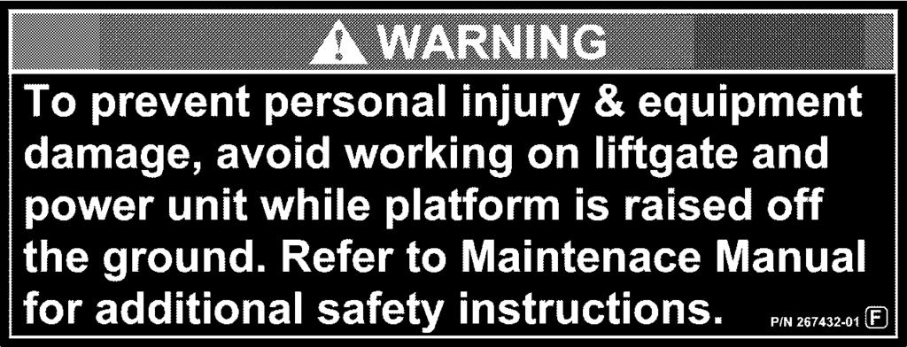
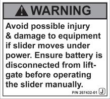
4 Comply with the following WARNINGS and SAFETY INSTRUCTIONS while installing Liftgates. See Operation Manual for operating safety requirements. WARNINGS! WARNING Do not stand, or allow obstructions, under the platform when lowering the Liftgate. Be sure your feet are clear of the Liftgate. Keep fingers, hands, arms, legs, and feet clear of moving Liftgate parts (and platform edges) when operating the Liftgate. Correctly stow platform when not in use. Extended platforms could create a hazard for people and vehicles passing by. Make sure vehicle battery power is disconnected while installing Liftgate. Connect vehicle battery power to the Liftgate only when installation is complete or as required in the installation instructions. If it is necessary to stand on the platform while operating the Liftgate, keep your feet and any objects clear of the inboard edge of the platform. Your feet or objects on the platform can become trapped between the platform and the Liftgate extension plate. Never perform unauthorized modifi cations on the Liftgate. Modifi cations may result in early failure of the Liftgate and may create hazards for Liftgate operators and maintainers. Recommended practices for welding on steel parts are contained in the current AWS (American Welding Society) D1.1 Structural Welding Code - Steel. Damage to Liftgate and/or vehicle, and personal injury can result from welds that are done incorrectly. Recommended practices for welding galvanized steel are contained in the current AWS (American Welding Society) D19.0 Welding Zinc-Coated Steel. Damage to Liftgate and/or vehicle, and personal injury can result from welds that are done incorrectly. 4
5 SAFETY INSTRUCTIONS SAFETY INSTRUCTIONS Read and understand the instructions in this Installation Manual before installing Liftgate. Before operating the Liftgate, read and understand the operating instructions in Operation Manual. Comply with all WARNING and instruction decals attached to the Liftgate. Keep decals clean and legible. If decals are illegible or missing, replace them. Free replacement decals are available from Maxon Customer Service. Consider the safety and location of bystanders and location of nearby objects when operating the Liftgate. Stand to one side of the platform while operating the Liftgate. Do not allow untrained persons to operate the Liftgate. Wear appropriate safety equipment such as protective eyeglasses, faceshield and clothing while performing maintenance on the Liftgate and handling the battery. Debris from drilling and contact with battery acid may injure unprotected eyes and skin. Be careful working by an automotive type battery. Make sure the work area is well ventilated and there are no fl ames or sparks near the battery. Never lay objects on the battery that can short the terminals together. If battery acid gets in your eyes, immediately seek fi rst aid. If acid gets on your skin, immediately wash it off with soap and water. If an emergency situation arises (vehicle or Liftgate) while operating the Liftgate, release the control switch to stop the Liftgate. A correctly installed Liftgate operates smoothly and reasonably quiet. The only noticeable noise during operation comes from the power unit while the platform is raised and lowered. Listen for scraping, grating and binding noises and correct the problem before continuing to operate Liftgate. NOTICE NOTICE Maxon Lift is responsible for the instructions to correctly install MAXON Liftgates on trucks or trailers only. Liftgate installers, not Maxon Lift, are responsible for reviewing and complying with all applicable Federal, State, and Local regulations pertaining to the trailer or truck. 5
6 VEHICLE REQUIREMENTS CAUTION To prevent damage to Liftgate and trailer, install stops on the slide rails to keep the sliding AA from hitting Liftgate. Refer to Liftgate clearance dimensions in this section of the manual. NOTE: BODY maximum and minimum operating bed height: Maximum height is 58-1/2 (Unloaded). Minimum height is 48 (Loaded). On vehicle bodies equipped with swing-open doors, the heel of platform may have to be notched to prevent interference from trailer. NOTE: Make sure vehicle is parked on level ground while preparing vehicle and installing Liftgate. NOTE: Dimensions are provided as reference for fi tting Liftgate to vehicle body. Check for correct clearances (FIG. 6-1, FIG. 7-1 and TABLE 7-1) on vehicle to prevent interference between vehicle and Liftgate. 10-1/2 MAX. 6 MIN. 24-3/4 27-3/4 MAX. 12-3/4 MIN. TRAILER CROSS MEMBER TRAILER FLOOR 92 SLIDE FRAME CHANNEL 1 MIN. 4 MAX. TRAILER SIDE DOOR 58-1/2 MAX. BED HEIGHT 48 MIN. BED HEIGHT SIDE VIEW OF LIFTGATE AS SEEN FROM REAR OF TRAILER FIG
7 VEHICLE REQUIREMENTS - Continued NOTE: Offset Liftgate 4-1/8 from the door opening to the outer edge of the slide frame (FIG. 7-1) so the platform will not hit the door when the door is open. MAIN FRAME (2 PLACES) SLIDE FRAME (2 PLACES) SHACKLE PLATE (2 PLACES) TRAILER CROSS MEMBER FLIPOVER C D E A B DOOR OPENING TOP OF TRAILER FLOOR 5 1/4 (SLIDE FRAME) SLIDE FRAME CHANNEL TRAILER SIDE DOOR AND LIFTGATE IN STOWED POSITION FIG. 7-1 A (FLIPOVER WIDTH) B (ACROSS SHACKLE PLATES) C (OVERALL WIDTH) 7 D (OUTER EDGE OF MAIN FRAME) E (OUTER EDGE OF SLIDE FRAME 49-1/ / /2 61-1/ / /2 83-1/ / /2 MOUNTING SPACE REQUIREMENTS TABLE 7-1
8 VEHICLE REQUIREMENTS - Continued NOTE: Center of crossmembers must be no more than 6 from outer edges of mainframe. If more than 6, consult the trailer manufacturer (FIGS. 8-1, 8-1A and 8-1B). OUTSIDE EDGE OF MAINFRAME 6 MAX. CENTER CROSSMEMBER CROSSMEMBER CENTER FIG. 8-1A FIG. 8-1B 6 MAX. OUTSIDE EDGE OF MAINFRAME CROSSMEMBER SPACING REQUIREMENTS FIG
9 STEP 1 - PREPARE LIFTGATE FOR INSTALLATION NOTE: RA Liftgates are equipped with mechanical and electrical controls that can be located on the LH side or RH side of the Liftgate. The Liftgate is shipped with stow latch, latch handle, and fl ipover latch on the LH side of the Liftgate. It is ready to mount on a trailer with the side door hinges on the RH side of the door. Liftgate will be offset to the LH side of the trailer door, opposite of the hinges. The external control switch and wall switches will also be mounted on the LH side of the door. If the trailer side door hinges are on the LH side, the mechanical controls (stow latch, latch handle and fl ipover latch) should be moved to the RH side of the Liftgate before the Liftgate is positioned and welded on the trailer cross members. In this case, the external control switches and wall switches will be mounted on the RH side of the trailer side door. The following instructions illustrate how to move the mechanical controls to the RH side of the Liftgate, if necessary. 9
10 STEP 1 - PREPARE LIFTGATE FOR INSTALLATION - Continued 1. If door hinges are mounted on the LH side of side door opening, disassemble stow latch and stow latch handle from LH side of liftgate, and reassemble on the RH side of the Liftgate (FIGS 10-1 and 10-1A). COTTER PIN, 1/2 LG. CLEVIS PIN, 1/4 X 7/8 LG. FIG FLAT WASHER, FLAT 1/4 LG. WASHER, M8 ROLL PIN, 1/4 X 1-1/2 LG. CAP SCREW, 5/16-18 X 2-1/2 LG. LINK BAR ROLL PIN, 1/4 X 1 LG. LEVER WELDMENT FLAT WASHER, 1/4 LG. FIG. 10-1A FLAT WASHER, M20 FLAT WASHER, M16 (2 PLACES) FLAT WASHER, 7/8 JAM NUT, 5/16-18 BEARING CLEVIS PIN, 1/4 X 7/8 LG. LATCH HOOK ROLL PIN, 1/4 X 1 LG. SPRING, 2-1/2 LG. EYEBOLT, #10-24 FLAT WASHER 7/8 JAM NUT, 5/16-18 LEVER HANDLE LOCK WASHER, 5/16 COTTER PIN, 1/2 LG. 10
11 STEP 1 - PREPARE LIFTGATE FOR INSTALLATION - Continued 2. Move proximity sensor to the RH side of Liftgate (FIGS and 11-1A). Then, route cable as shown in FIG. 11-1B. FIG CABLE RH CABLE ROUTING (REAR VIEW) FIG. 11-1B PROXIMITY SENSOR LOCK WASHER RH PROXIMITY SENSOR FIG. 11-1A NUT (REF) 11
12 STEP 1 - PREPARE LIFTGATE FOR INSTALLATION - Continued 3. Move latch handle and retention ramp hook to the RH side of Liftgate (FIGS. 12-1, 12-1A and 12-1B). RIVET, 3/8 X 7/16 LG. (2 PLACES) SPRING HOOK (2 PLACES) FLAT WASHER, 3/8 ROLL PIN, 5/32 X 5/8 LG. NYLON WASHER, 1/4 (2 PLACES) LATCH SPRING LOCK NUT, 3/8-16 CLEVIS PIN, 1/4 X 1-5/8 LG. RETAINER RING, 1/2 RIVET, 3/8 X 7/16 LG. (2 PLACES) HEX NUT, 1/4-20 SPRING HOOK (2 PLACES) FLAT WASHER, 3/8 (3 PLACES) LATCH HANDLE NYLON WASHER, 1/2 RETENTION RAMP HOOK ROLL PIN, 5/32 X 5/8 LG. CAP SCREW, 3/8-16 X 2-1/2 LG. NYLON WASHER, 1/4 (2 PLACES) FLAT WASHER, 1/4 FIG CAP SCREW, 3/8-16 X 2-1/2 LG. FLAT WASHER, 3/8 (2 PLACES) LATCH SPRING FLAT WASHER, 3/8 NYLON WASHER, 1/2 RETAINER RING, 1/2 RETENTION RAMP HOOK RH HOOK FIG. 12-1A LATCH HANDLE FLAT WASHER, 1/4 RH LATCH HANDLE FIG. 12-1B HEX NUT, 1/
13 STEP 2 - WELD LIFTGATE ON TRAILER ` WARNING! Use weld blankets to protect lines and tubes from weld splatter.! WARNING Welding on galvanized parts gives off especially hazardous fumes. To minimize hazard remove galvanizing from weld area, provide adequate ventilation, and wear suitable respirator. CAUTION! To avoid personal injury, use at least 2 people to position Liftgate. NOTE: For installation of this Liftgate, the maximum distance from bottom of trailer cross members to top of trailer fl oor is 10-1/2 max. NOTE: Liftgate must be welded to at least 6 fi xed trailer crossmembers that are typically spaced 12 between centers. NOTE: Ideal installation is for edge of platform to be aligned with door opening (FIG. 20-2). NOTE: Switches, stow mechanism, latch release handle and platform latch may be located on either side of the Liftgate during installation, depending on location of trailer door hinges. 13
14 STEP 2 - WELD LIFTGATE ON TRAILER - Continued 1. With forklift, position the Liftgate perpendicular to the side of trailer (FIG 14-1), with latch release handle opposite of door hinges (FIGS and 14-2A). DOOR HINGES FIG /4 DOOR OPENING FIG. 14-2A SLIDE FRAME LATCH RELEASE HANDLE FIG PLATFORM 14
15 STEP 2 - WELD LIFTGATE ON TRAILER - Continued 2. Position Liftgate to trailer by butting the slide frame against the bottom of trailer cross members according to the X and Y dimensions as shown in FIGS. 15-1, 15-1A and TABLE Y (TOP OF TRAILER FLOOR TO BOTTOM OF CROSSMEMBER) 10-5/8 9-1/2 9-1/2 8-1/2 8-1/2 7-1/2 7-1/2 6 Y (TABLE 15-1) TRAILER CROSSMEMBER SIDE VIEW OF LIFTGATE AS SEEN FROM REAR OF TRAILER FIG TOP OF TRAILER FLOOR X (TABLE 15-1) FIG. 15-1A X (FRONT OF LIFTGATE FRAME TO OUTER TRAILER WALL) RH WALL OF TRAILER FRONT OF LIFTGATE FRAME TABLE
16 STEP 2 - WELD LIFTGATE ON TRAILER - Continued 3. Tack weld Liftgate slide frame to trailer cross members (FIG. 16-1). 12 MINIMUM BETWEEN CENTERS 1/4 SLIDE FRAME CHANNEL TACK ACCESSIBLE CHANNELS TO TRAILER CROSSMEMBERS REAR OF TRAILER TRAILER CROSS MEMBER RH SIDE OF TRAILER BOTTOM VIEW OF TRAILER WITH LIFTGATE SLIDE FRAME CHANNELS POSITIONED ON CROSSMEMBERS (SLIDE ASSEMBLY AND PARTS OF SLIDE FRAME NOT SHOWN) FIG
17 STEP 3 - LEVELING PLATFORM NOTE: Make sure Liftgate is tack-welded to trailer before connecting power. NOTE: If necessary, external 12 VDC power may be used in place of batteries for initial platform leveling adjustments. 1. Connect IN-OUT and UP-DOWN switches to main wiring harness so slide assembly and platform can be repositioned (FIG. 17-1). Then, ensure Liftgate batteries are connected as shown in (FIG 17-2). CIRCUIT BREAKER WALL SWITCH CONNECTOR HARNESS FEMALE CONNECTOR RED UP-DOWN SWITCH MALE CONNECTOR RED FIG GROUND IN-OUT SWITCH TO SWITCHES BATTERY DISCONNECT SWITCH RED TO STARTER SOLENOID BLACK BLACK FIG
18 STEP 3 - LEVELING PLATFORM - Continued CAUTION Operate Liftgate with caution and no load until installation is complete. CAUTION Limit switch is activated when the platform is raised and not fully in the OUT position (FIG. 18-2). If the limit switch does not activate, the parallel arms, stow latch mechanism, and trailer can be damaged. To prevent Liftgate and trailer damage, make sure limit switch roller arm is adjusted correctly. NOTE: Refer to Operating Instructions decal and applicable WARNING & CAUTION decals. 2. To adjust roller arm, loosen roller arm adjustment screw (FIG. 18-1). If the roller doesn t connect with the center of the roller plate (FIG. 18-2), slide the roller arm out a little to make it longer (FIG. 18-1). If the roller extends past the roller plate (FIG. 18-2), slide the roller arm in a little to make it shorter (FIG. 18-1). Tighten roller arm adjustment screw (FIG. 18-1). ROLLER ARM ADJUSTMENT SCREW ROLLER ARM ADJUSTING ROLLER ARM FIG ROLLER ARM ROLLER ROLLER PLATE CORRECT POSITION OF ROLLER FIG
19 STEP 3 - LEVELING PLATFORM - Continued NOTE: Lever rod is adjusted correctly when the limit switch is activated if the slider is not fully in the OUT position and the platform is raised (FIG. 19-2). The limit switch will not activate when the slider is in the OUT position and the platform is raised (FIG. 19-3). 3. To adjust lever rod, loosen locking nut and rotate lever rod adjustment screw. If the platform will not raise when slide assembly is fully extended OUT, turn lever rod adjustment screw clockwise (FIGS and 19-1A). If the platform can be raised when slide assembly is not fully extended OUT, turn lever rod adjustment screw counterclockwise (FIG. 19-1). Tighten locking nut. LEVER ROD ROTATING LEVER ROD ADJUSTMENT SCREW FIG LIMIT SWITCH LEVER ROD TILT ARM LEVER ROD ADJUSTMENT SCREW LOCKING NUT FIG. 19-1A ACTIVATING LIMIT SWITCH FIG SLIDE ASSEMBLY LIMIT SWITCH SLIDER ASSEMBLY LEVER ROD TILT ARM NOT ACTIVATING LIMIT SWITCH FIG
20 STEP 3 - LEVELING PLATFORM - Continued NOTE: Platform plates can be unbolted to move and trim as needed to clear the door opening for right or left offset installations. After trimming platform plates, all raw edges should be touched up with galvanize zinc paint. 4. Run slide assembly out and unfold the fl ipover. Then, raise platform to fl oor level making sure not to hit trailer wall (FIG. 20-1). If necessary, relocate and/or trim platform plate so it clears door opening (FIG. 20-2). TRAILER WALL DOOR OPENING PLATFORM LH PLATE OFFSET PLATFORM DOOR OPENING PLATFORM PLATE PLATFORM RAISED TO FLOOR FIG PLATFORM PLATFORM DOOR OPENING PLATFORM PLATE TRAILER WALL RH OFFSET TRAILER FLOOR LH & RH PLATFORM OFFSET INSTALLATIONS (SINGLE PLATFORM PLATE NOT SHOWN) FIG
21 STEP 3 - LEVELING PLATFORM - Continued NOTE: The slide stop bolts move the platform 1/2 per each hole. The fine adjustment moves the platform 3/8. 5. If needed, move slide stop bolts to level platform with trailer fl oor as shown in FIGS and 21-1A. Bolting the stop closer to the trailer wall will stop slider closer to trailer wall and allow the platform to be raised higher. Bolting the stops farther away from trailer wall will stop slider farther from the trailer wall and decrease the height platform can be raised. 6. With platform at fl oor level, turn stop block bolts COUNTERCLOCKWISE until butted against each lift arm as shown in FIG. 21-1B. This will prevent the platform from hitting the trailer wall. SLIDE STOP BOLTS (COARSE ADJUSTMENT) PLATFORM FLIPOVER IN-OUT SLIDE STOP ADJUSTMENT (BOTTOM VIEW) FIG. 21-1A PLATFORM FLUSH WITH VEHICLE FLOOR FIG TRAILER FLOOR STOP BLOCK BOLT LIFT ARM STOP BLOCK BOLT FIG. 21-1B 21
22 STEP 3 - LEVELING PLATFORM - Continued 7. Check for 1/4 minimum clearance between heel of platform and wall of trailer (FIG. 22-1A), and ensure the platform plate overlaps the trailer door opening (FIGS and 22-1A). If necessary, turn fi ne adjustment bolt to get the minimum 1/4 distance (FIGS. 22-1A and 22-1B). Turning the bolt COUNTERCLOCKWISE will increase the distance, turning the bolt CLOCKWISE will decrease the distance. FINE ADJUSTMENT (FRONT VIEW) FIG. 22-1B FINE ADJUSTMENT BOLT FLIPOVER PLATFORM PLATE EDGE OF PLATFORM PLATFORM 1/4 MIN. FIG. 22-1A TRAILER WALL TRAILER FLOOR PLATFORM FLUSH WITH VEHICLE FLOOR FIG
23 STEP 4 - FINISH WELDING LIFTGATE Weld slide frame to tailer crossmembers as shown in FIGS /16 3/16 WELD 5 CHANNELS ON BOTH SIDES TO TRAILER CROSSMEMBERS REAR OF TRAILER TRAILER CROSS MEMBER SLIDE FRAME CHANNEL RH SIDE OF TRAILER LIFTGATE BOTTOM VIEW OF TRAILER WITH LIFTGATE SLIDE FRAME CHANNELS POSITIONED ON CROSSMEMBERS (SLIDE ASSY AND PARTS OF SLIDE FRAME NOT SHOWN) FIG
24 STEP 5 - ATTACH CONTROL SWITCHES TO TRAILER NOTE: Wall switches, control switches, latch release handle, latch and proximity sensor may be located on either side of the Liftgate during installation, depending on location of trailer door hinges. Components are located on LH side of Liftgate when shipped, to reposition to the RH side of side door, see FIG TOP WALL SWITCH BOTTOM WALL SWITCH EXTENSION CABLE (NOT USED WHEN MOVING CONTROLS TO RH SIDE) INSIDE TRAILER CONTROL SWITCH BRACKET (REAR VIEW) LATCH RELEASE HANDLE LATCH PROXIMITY SENSOR COMPONENTS REPOSITIONED TO RH SIDE OF DOOR FIG
25 STEP 5 - ATTACH CONTROL SWITCHES TO TRAILER - Continued 1. Disconnect battery power from Liftgate. 2. Unbolt IN-OUT switch and UP-DOWN switch from bracket as shown in FIG LOCK NUT #10-24 (4 PLACES) FIG BRACKET IN-OUT SWITCH UP-DOWN SWITCH PAN HEAD SCREW #10-24 X 3/4 (4 PLACES) 25
26 STEP 5 - ATTACH CONTROL SWITCHES TO TRAILER - Continued CAUTION Prevent damage to switches and harness by using a protective cover such as a welding blanket to cover switches and harness. NOTE: Angle must be welded on 2 cross members. 3. Position angle on nearest crossmembers by latch release handle (FIGS. 26-1, 26-1A and 26-1B). Then, weld angle to the 2 crossmembers (FIG. 26-1B). ANGLE TRAILER CROSSMEMBERS TRAILER CROSSMEMBER 5-3/4 (REF) SIDE VIEW MOUNTING ANGLE FIG. 26-1A INSIDE TRAILER WALL LATCH RELEASE LIFTGATE HANDLE FRONT VIEW OF LIFTGATE WITH PLATFORM RAISED TO BED LEVEL FIG ANGLE FIG. 26-1B 3/16 3/16 WELD BOTH SIDES TO 2 CROSSMEMBERS 26
27 STEP 5 - ATTACH CONTROL SWITCHES TO TRAILER - Continued 4. Position control switch bracket on angle as shown in FIGS and 27-1A. Ensure angle and bracket position will not put strain on the control switch cables. Then, weld switch bracket to angle as shown in FIG. 27-1B. TRAILER CROSSMEMBER ANGLE TRAILER CROSSMEMBERS SIDE VIEW OF CONTROL SWITCH BRACKET FIG. 27-1A TRAILER WALL SWITCH BRACKET FRONT VIEW OF LIFTGATE WITH PLATFORM RAISED TO BED LEVEL FIG ANGLE 3/16 FIG. 27-1B SWITCH BRACKET 27
28 STEP 5 - ATTACH CONTROL SWITCHES TO TRAILER - Continued 5. Bolt IN-OUT and UP-DOWN control switches to bracket as shown in FIGS and 28-1A. TRAILER FLOOR LOCK NUT #10-24 (4 PLACES) IN-OUT SWITCH UP-DOWN SWITCH RH TRAILER WALL FIG BRACKET FIG. 28-1A PAN HEAD SCREW #10-24 X 3/4 (4 PLACES) 28
29 STEP 5 - ATTACH CONTROL SWITCHES TO TRAILER - Continued 6. Route and connect electrical harness to bracket-mounted switches and wall-mounted switches as shown in FIGS. 29-1, 29-2, and 29-2A. ELECTRICAL HARNESS TRAILER FLOOR TO SWITCHES BATTERY BOX WALL MOUNT SWITCH HARNESSES FIG PUMP BOX PLASTIC TIE WALL SWITCHES BRACKET MOUNT SWITCHES FIG. 29-2A CONTROL SWITCH BRACKET (REAR VIEW) INSIDE TRAILER ELECTRICAL HARNESS ROUTED UNDER TRAILER FLOOR FIG
30 STEP 5 - ATTACH CONTROL SWITCHES TO TRAILER - Continued 7. Reconnect IN-OUT and UP-DOWN switches to electrical harness as shown in FIG and 30-1A. CONTROL SWITCH HARNESS MALE CONNECTOR FEMALE CONNECTOR FEMALE CONNECTOR MALE CONNECTOR FIG. 30-1A UP-DOWN SWITCH IN-OUT SWITCH BRACKET (REAR VIEW) CONNECTING ELECTRICAL HARNESS TO SWITCHES FIG
31 STEP 5 - ATTACH CONTROL SWITCHES TO TRAILER - Continued NOTE: Unused terminals must be wrapped and sealed with shrink wrap, and exposed wires must be covered with loom included with the Liftgate. 8. Mark and drill 1 hole through vehicle fl oor as shown in FIG Route wall switch harness through hole as shown in FIG Connect switch harness to the main harness as shown in FIG. 31-1A. TRAILER FLOOR CONNECTING ELECTRICAL HARNESS TO SWITCHES FIG FEMALE CONNECTOR WIRE LOCKING WEDGE WALL SWITCH HARNESS 1 HOLE WALL SWITCH HARNESS MALE CONNECTOR WIRE MAIN HARNESS FIG. 31-1A 31
32 STEP 5 - ATTACH CONTROL SWITCHES TO TRAILER - Continued NOTE: Mount control switches on outside wall opposite hinges and on same side as latch release handle. 11. Measure, mark, and drill 2-1/4 hole, in 2 places, on the trailer side wall as shown in FIG TRAILER FLOOR 2-1/4 HOLE 45 8 LATCH RELEASE HANDLE 2-1/4 HOLE DOOR HINGES MEASURING AND MARKING HOLES FOR WALL-MOUNTED SWITCHES FIG LIFTGATE 32
33 STEP 5 - ATTACH CONTROL SWITCHES TO TRAILER - Continued 12. Fasten wall switches to trailer wall with self drilling screws as shown in FIG and 33-1A. SELF DRILLING SCREW #8-18 (3 PLACES) WALL MOUNT SWITCH FIG. 33-1A RH TRAILER WALL TRAILER FLOOR FIG TRAILER SIDE DOOR OPENING (DOOR NOT SHOWN) 33
34 STEP 5 - ATTACH CONTROL SWITCHES TO TRAILER - Continued NOTE: After assembly, MAXON recommends to seal all connections with NCP-2 corrosion preventive sealer from NOCO or equivalent. 13. Splice top wall switch harness to bottom wall switch harness as shown in FIGS and 34-1A. BLACK WIRE BUTT SPLICE (4 PLACES) TOP WALL SWITCH HARNESS GREEN WIRE BLACK WIRE BOTTOM WALL SWITCH WHITE WIRE BLACK WIRE BOTTOM WALL SWITCH HARNESS RED WIRE FIG. 34-1A WHITE WIRE GREEN WIRE WHITE WIRE RED WIRE RED WIRE GREEN WIRE VIEW OF WALL SWITCHES FROM INSIDE TRAILER FIG
35 STEP 6 - ATTACH STOW LIGHT TO TRAILER NOTE: Stow light will warn vehicle driver if the Liftgate is not stowed. Light must be positioned so the driver can see the light from the LH sideview mirror. 1. Connect stow light to stow light harness (FIGS and 35-1A). 2. Position stow light on trailer as shown in FIGS and 35-2A. Fasten stow light on front LH corner of trailer with self drilling screws (FIG. 35-2A). STOW LIGHT WHITE WIRE WHITE WIRE FIG. 35-1A BLACK WIRE BLACK WIRE STOW LIGHT HARNESS STOW LIGHT FIG STOW LIGHT STOW LIGHT HARNESS SELF DRILLING SCREW #8-18 (4 PLACES) FRONT LH CORNER FIG. 35-2A FRONT OF TRAILER FIG
36 STEP 6 - ATTACH STOW LIGHT TO TRAILER - Continued 3. Route and connect stow light cable to signal cable connectors extending from the conduit as shown in FIGS and 36-1A. STOW LIGHT CABLE BLACK BLACK WHITE CONNECTING STOW LIGHT CABLE FIG. 36-1A SIGNAL CABLE STOW LIGHT CONDUIT WHITE CONDUIT & SIGNAL CABLE STOW LIGHT CABLE ROUTING STOW LIGHT CABLE FIG
37 STEP 7 - RECOMMENDED LIFTGATE POWER CONFIGURATION NOTE: Make sure the Liftgate power unit, and all batteries on the vehicle for the power unit, are connected correctly to a common chassis ground. Charge lines for the Liftgate are typically installed on trailers as show in FIG LIFTGATE BATTERY/PUMP BOX CHARGE LINE CONNECTION FIG POLE CHARGE LINES TRACTOR BATTERIES 37
38 ATTACH DECALS CAUTION DECAL P/N DECAL C DECAL B CAUTION DECAL P/N DECAL A DECAL F CAPACITY DECAL (RA-35 ONLY) P/N CAPACITY DECAL (RA-45 ONLY) P/N OPERATION DECAL P/N SERIAL PLATE (REF) FIG
39 ATTACH DECALS - Continued DECAL SHEET P/N FIG
40 DECAL POSITIONS DECAL P/N DECAL P/N DECAL P/N DECAL L DECAL K DECAL J DECAL F DECAL I DECAL M DECAL K DECAL L DECAL F DECAL M MAXON CONSPICUITY TAPE (BOTH SIDES) P/N FIG


41 DECAL POSITIONS - Continued DECAL SHEET P/N FIG
42 SYSTEM DIAGRAMS PUMP & MOTOR SOLENOID OPERATION LIFTGATE FUNCTION S2 VALVE PORT A PUMP AND MOTOR FIG POWER UNIT MOTOR & SOLENOID OPERATION PORT STARTER SOLENOID MOTOR SOLENOID OPERATION ( MEANS ENERGIZED) VALVE S1 S1 VALVE S3 VALVE VALVE S2 PORT B PORT L PORT T VALVE S3 RAISE L MOTOR LOCK VALVE LOWER T SLIDE OUT A SLIDE IN B REFER TO VALVES SHOWN ON HYDRAULIC SCHEMATIC TABLE
43 SYSTEM DIAGRAMS - Continued HYDRAULIC SCHEMATIC NOTE: PRV (PRESSURE RELIEF VALVE) FIG
44 SYSTEM DIAGRAMS - Continued ELECTRICAL SCHEMATIC FIG
45 SYSTEM DIAGRAMS - Continued STOW SIGNAL ELECTRICAL SCHEMATIC FIG
46 OPTIONS OPTIONAL LIFTGATE COMPONENTS MISCELLANEOUS KITS PART NO. CYCLE COUNTER MUD GUARD EXTRA CONTROLS AND CONTROL KITS HAND HELD CONTROL WALL SWITCH KITS RECESSED WALL SWITCHES OUTSIDE WALL SWITCHES BATTERY CABLE KITS 16 BATTERY CABLE INSTALLATION BATTERY CABLE INSTALLATION BATTERY CABLE INSTALLATION BATTERY CABLE INSTALLATION LIGHT KITS FLASHING LIGHTS, FOR 82 WIDTH FLASHING LIGHTS, FOR 60 WIDTH FLASHING LIGHTS, FOR 48 WIDTH WORK LIGHTS TRAILER FRONT LIGHTS TABLE
INSTALLATION MANUAL DMD-22 & DMD-33
 M-12-20 REV. E JULY 2016 INSTALLATION MANUAL DMD-22 & DMD-33 To fi nd maintenance & parts information for your DMD Liftgate, go to www.maxonlift. com. Click the PRODUCTS, RAILIFT & DMD buttons. Open the
TE-20 & INSTALLATION MANUAL M REV. F SEPTEMBER 2015
 M-12-04 REV. F SEPTEMBER 2015 INSTALLATION MANUAL TE-20 & 72-150 To find maintenance & parts information for your TE-20 & 72-150 Liftgate, go to www.maxonlift.com. Click the PRODUCTS, TUK-A-WAY and TE-20
M REV. F AUGUST 2014 INSTALLATION MANUAL
 M-06-02 REV. F AUGUST 2014 INSTALLATION MANUAL MAXON Lift Corp. 2014 TABLE OF CONTENTS SUMMARY OF CHANGES: M-06-02, REVISION F... 4 SAFETY INSTRUCTIONS... 5 WARNINGS... 5 MM-1300 LIFTGATE COMPONENTS...
M APRIL 2012 INSTALLATION MANUAL DMD-22 & DMD-33
 M-11-13 APRIL 2012 INSTALLATION MANUAL DMD-22 & DMD-33 MAXON Lift Corp. 2012 TABLE OF CONTENTS WARNINGS... 3 NOTICE... 4 VEHICLE REQUIREMENTS... 5 BODY STRENGTH... 5 INSTALLED LIFTGATE... 7 LIFTGATE INSTALLATION
OPERATION MANUAL RA-35 & RA-45
 M-13-02 REV. A NOVEMBER 2015 OPERATION MANUAL RA-35 & RA-45 To fi nd maintenance & parts information for your RA Liftgate, go to www.maxonlift.com. Click the PRODUCTS, SLIDELIFT & RA buttons. Open the
PRODUCT DOCUMENTATION PARTS PORTAL RAILIFT & DMD MAXON
 M-16-38 JUNE 2018 To fi nd maintenance & parts information for your DMD Liftgate, go to www.maxonlift. com. Click the PRODUCTS, RAILIFT & DMD buttons. Open the Maintenance Manual in the PRODUCT DOCUMENTATION
M REV B SEPTEMBER 2017
 M-16-33 REV B SEPTEMBER 2017 To fi nd maintenance & parts information for your TE-25 or TE-30 Liftgate, go to www. maxonlift.com. Click the PRODUCTS, TUK-A-WAY and TE-25/TE-30 buttons. Open the Maintenance
M REV. A APRIL 2008 INSTALLATION MANUAL
 M-06-14 REV. A APRIL 2008 INSTALLATION MANUAL MAXON Lift Corp. 2008 TABLE OF CONTENTS WARNINGS... 3 STANDARD LIFTGATE COMPONENTS... 4 GPTWR-3 SERIES INSTALLATION PARTS BAGS... 5 VEHICLE REQUIREMENTS...
M SEPTEMBER 2017
 M-17-33 SEPTEMBER 2017 To fi nd maintenance & parts information for your TE-15 or TE-20 Liftgate, go to www. maxonlift.com. Click the PRODUCTS, TUK-A-WAY and TE-15/TE-20 buttons. Open the Maintenance Manual
M REV. D APRIL 2008 INSTALLATION MANUAL GPTLR-25, GPTLR-33, GPTLR-44, & GPTLR-55
 M-04-06 REV. D APRIL 2008 INSTALLATION MANUAL GPTLR-25, GPTLR-33, GPTLR-44, & GPTLR-55 MAXON Lift Corp. 2008 TABLE OF CONTENTS GPTLR LIFTGATE COMPONENTS... 5 GPTLR-SERIES INSTALLATION PARTS BOX... 6 VEHICLE
M JULY 2017 GPTLR Liftgate www. maxonlift.com PRODUCTS, TUK-A-WAY GPTLR Maintenance Manual PRODUCT DOCUMENTATION PARTS PORTAL TUK-A-WAY GPTLR
 M-16-24 JULY 2017 To find maintenance information for your GPTLR Liftgate, go to www. maxonlift.com. Click the PRODUCTS, TUK-A-WAY & GPTLR buttons. Open the Maintenance Manual in the PRODUCT DOCUMENTATION
INSTALLATION MANUAL TE-33, TE-33L & TEWR-33 M REV. K DECEMBER 2016
 M-11-06 REV. K DECEMBER 2016 INSTALLATION MANUAL TE-33, TE-33L & TEWR-33 To fi nd maintenance information for your TE-33 Liftgate, go to www.maxonlift.com. Click the PRODUCTS, TUK-A-WAY & TE-33 buttons.
OPERATION MANUAL. Me2-Series C LB CAPACITY C LB CAPACITY C LB CAPACITY
 M-14-36 AUGUST 2015 OPERATION MANUAL Me2-Series C2 1300 LB CAPACITY C2 1500 LB CAPACITY C2 1600 LB CAPACITY LIFT CORP. To fi nd maintenance & parts information for your Me2 Liftgate, go to www.maxonlift.com.
M REV. B AUGUST 2010 INSTALLATION MANUAL GPTWR-3
 M-08-36 REV. B AUGUST 2010 INSTALLATION MANUAL GPTWR-3 MAXON Lift Corp. 2010 TABLE OF CONTENTS WARNINGS... 3 SAFETY INSTRUCTIONS... 3 STANDARD LIFTGATE COMPONENTS... 4 GPTWR-3 INSTALLATION PARTS BAGS...
M REV. C AUGUST 2008
 M-01-22 REV. C AUGUST 2008 Installation Manual Contains: Warnings Requirements - Body Strength & Installed Liftgate Liftgate Installation Components Liftgate Component Installation Instructions Hydraulic
M REV. E JUNE 2009 OPERATION MANUAL GPTLR-25, GPTLR-33, GPTLR-44 & GPTLR-55
 M-04-05 REV. E JUNE 2009 OPERATION MANUAL GPTLR-25, GPTLR-33, GPTLR-44 & GPTLR-55 MAXON Lift Corp. 2009 TABLE OF CONTENTS WARNINGS...4 LIFTGATE TERMINOLOGY...5 RECOMMENDED DAILY OPERATION CHECKS...6 DECALS...8
INSTALLATION MANUAL M REV. G AUGUST 2016
 M-09-24 REV. G AUGUST 2016 INSTALLATION MANUAL To fi nd maintenance & parts information for your GPC Liftgate, go to www.maxonlift.com. Click the PRODUCTS, CONVENTIONAL & GPC buttons. Open the Maintenance
M REV. L AUGUST 2012
 M-00-24 REV. L AUGUST 2012 Installation Manual Contains: Warnings Requirements - Body Strength & Installed Liftgate Liftgate Installation Components Liftgate Component Installation Instructions Hydraulic
M REV. C MARCH 2011 OPERATION MANUAL GPSLR-33 & GPSLR-44
 M-08-13 REV. C MARCH 2011 OPERATION MANUAL GPSLR-33 & GPSLR-44 MAXON Lift Corp. 2011 TABLE OF CONTENTS WARNINGS... 4 LIFTGATE TERMINOLOGY... 5 RECOMMENDED DAILY OPERATION CHECKS... 6 DECALS (WITH SMART
M REV. J APRIL 2012 OPERATION MANUAL GPTLR-25, GPTLR-33, GPTLR-44 & GPTLR-55
 M-04-05 REV. J APRIL 2012 OPERATION MANUAL GPTLR-25, GPTLR-33, GPTLR-44 & GPTLR-55 MAXON Lift Corp. 2012 TABLE OF CONTENTS WARNINGS...4 LIFTGATE TERMINOLOGY...5 RECOMMENDED DAILY OPERATION CHECKS...6
M REV. M SEPTEMBER 2013
 M-00-25 REV. M SEPTEMBER 2013 Operation Manual Contains: Warnings Decal & Plate Locations Standard Control Locations Liftgate & Retention Ramp Operation MAXON Lift Corp. 2013 KEEP THIS MANUAL IN CAB OF
RCM-1250 C RCM-1250 C AB RCM-1600 RCM-1600 C AB
 M-91-17 REV. E AUGUST 2012 INSTALLATION MANUAL RCM-1250 C RCM-1250 C AB RCM-1600 RCM-1600 C AB LIFT CORP. 11921 Slauson Avenue Santa Fe Springs, CA 90607 (800) 227-4116 MAXON Lift Corp. 2012 TABLE OF CONTENTS
M REV. C AUGUST 2017
 M-16-10 REV. C AUGUST 2017 Installation Manual Contains: Warnings & Safety Instructions Requirements - Body Strength & Installed Liftgate Liftgate Installation Components Liftgate Component Installation
M REV. H JUNE 2015 OPERATION MANUAL MTB-25 & MTB-30
 M-00-40 REV. H JUNE 2015 OPERATION MANUAL MTB-25 & MTB-30 To find maintenance & parts information for your MTB-25 & MTB-30 Liftgate, go to www. maxonlift.com. Click the PRODUCTS, MTB- 25 & MTB-30 buttons.
PRODUCT DOCUMENTATION PARTS PORTAL
 M-16-25 JULY 2017 To find maintenance & parts information for your GPTLR Liftgate, go to www. maxonlift.com. Click the PRODUCTS, TUK-A-WAY & GPTLR buttons. Open the Maintenance Manual in the PRODUCT DOCUMENTATION
M REV. A DECEMBER 2016
 M-16-10 REV. A DECEMBER 2016 Installation Manual Contains: Warnings & Safety Instructions Requirements - Body Strength & Installed Liftgate Liftgate Installation Components Liftgate Component Installation
TKL-25 OPERATION MANUAL
 TKL-25 OPERATION MANUAL M-98-09 REV. C FEBRUARY 2004 KEEP THIS MANUAL IN CAB OF VEHICLE For a free copy of other manuals that pertain to this Liftgate, please visit our website at www.maxonlift.com or
M REV. B FEBRUARY 2016
 M-14-21 REV. B FEBRUARY 2016 Installation Manual Contains: Warnings & Safety Instructions Requirements - Body Strength & Installed Liftgate Liftgate Installation Components Liftgate Component Installation
M REV. D AUGUST 2010 OPERATION MANUAL GPT-25, GPT-3, GPT-4, GPT-5, & GPTWR-3
 M-08-34 REV. D AUGUST 2010 OPERATION MANUAL GPT-25, GPT-3, GPT-4, GPT-5, & GPTWR-3 MAXON Lift Corp. 2010 TABLE OF CONTENTS LIFTGATE TERMINOLOGY... 5 RECOMMENDED DAILY OPERATION CHECKS... 6 DECALS (GPT
INSTALLATION INSTRUCTIONS
 INSTALLATION INSTRUCTIONS FOR WHEELCHAIR LIFT MODEL NO. WL7-vers. B DOT-Public Use Lift PATENTS PENDING MAXON Lift Corp. 2006 MP-06-01 REV. B AUGUST 2006 PATENTS PENDING TABLE OF CONTENTS INTRODUCTION...4
M AUGUST 2018 MAXON
 M-16-40 AUGUST 2018 MAXON Lift Corp. 2018 LIFT CORP. 11921 Slauson Ave. Santa Fe Springs, CA. 90670 CUSTOMER SERVICE: TELEPHONE (562) 464-0099 TOLL FREE (800) 227-4116 FAX: (888) 771-7713 NOTE: For latest
M-90-1 REV. F SEPTEMBER 2010 INSTALLATION MANUAL RC-2B RC-3B RC-4B RC-5B RC-6B RC-6K
 M-90-1 REV. F SEPTEMBER 2010 INSTALLATION MANUAL RC-2B RC-3B RC-4B RC-5B RC-6B RC-6K 11921 Slauson Avenue. Santa Fe Springs, CA. 90670 (800) 227-4116 MAXON Lift Corp. 2010 TABLE OF CONTENTS WARNINGS...
INSTRUCTIONS, FLASHING LIGHT INSTALLATION KIT
 LIFT CORPORATION Sht. 1 of 9 DSG# M-13-06 Rev. A Date: 03/10/14 INSTRUCTIONS, FLASHING LIGHT INSTALLATION KIT KIT P/N 286755-01 (BMRSD WITH ALUMINUM FLIPOVER & FIXED RAMP) LOCK WASHER, 1/4 P/N 902011-2
M MARCH 2002 Parts Manual Contains:
 M-0- MARCH 00 Parts Manual Contains: Warranty Information Warnings Parts Ordering Information Exploded View Parts Breakdowns LIFT CORP. 9 Slauson Ave. Santa Fe Springs, CA. 900 CUSTOMER SERVICE: TELEPHONE
M OCTOBER 2017 MAXON
 M-17-08 OCTOBER 2017 MAXON Lift Corp. 2017 LIFT CORP. 11921 Slauson Ave. Santa Fe Springs, CA. 90670 CUSTOMER SERVICE: TELEPHONE (562) 464-0099 TOLL FREE (800) 227-4116 FAX: (888) 771-7713 NOTE: For latest
INSTRUCTIONS, RAM DUAL REAR WHEEL TRUCKS INSTALLATION KIT (C2 LIFTGATES)
") LIFT CORPORATION Sht. 1 of 23 DSG# M-15-25 Rev. B Date: 05/31/2017 INSTRUCTIONS, RAM DUAL REAR WHEEL TRUCKS INSTALLATION KIT (C2 LIFTGATES) RAM 3500 DUAL REAR WHEEL PICKUP TRUCKS, 2013 TO 2015 KIT P/N
LIFT CORPORATION Sht. 1 of 23 DSG# M-15-25 Rev. B Date: 05/31/2017 INSTRUCTIONS, RAM DUAL REAR WHEEL TRUCKS INSTALLATION KIT (C2 LIFTGATES) RAM 3500 DUAL REAR WHEEL PICKUP TRUCKS, 2013 TO 2015 KIT P/N
M REV. K SEPTEMBER Parts Manual Contains: Warranty Information Warnings Parts Ordering Information Exploded View Parts Breakdowns
 M-07- REV. K SEPTEMBER 03 Parts Manual Contains: Warranty Information Warnings Parts Ordering Information Exploded View Parts Breakdowns MAXON Lift Corp. 03 LIFT CORP. 9 Slauson Ave. Santa Fe Springs,
INSTRUCTION, GPT HAND PUMP KIT INSTALLATION GPT KIT P/N
 LIFT CORPORATION Sht. 1 of 28 DSG# M-09-16 Rev. B Date: 4/22/2014 INSTRUCTION, GPT HAND PUMP KIT INSTALLATION GPT KIT P/N 283330-01 NEEDLE VALVE, ADJUSTABLE, SAE #6 P/N 906739-01 QTY. 1 CONNECTOR, SAE
INSTRUCTION, DODGE TRUCKS INSTALLATION KIT (C2 LIFTGATES)
") LIFT CORPORATION Sht. 1 of 23 DSG# M-14-25 Rev. B Date: 05/16/17 INSTRUCTION, DODGE TRUCKS INSTALLATION KIT (C2 LIFTGATES) DODGE 1500 PICKUPS, 2002 TO 2016 DODGE 2500 PICKUPS, 2003 TO 2016 KIT P/N 289492-01
LIFT CORPORATION Sht. 1 of 23 DSG# M-14-25 Rev. B Date: 05/16/17 INSTRUCTION, DODGE TRUCKS INSTALLATION KIT (C2 LIFTGATES) DODGE 1500 PICKUPS, 2002 TO 2016 DODGE 2500 PICKUPS, 2003 TO 2016 KIT P/N 289492-01
M REV. B JANUARY 2013 OPERATION & MAINTENANCE MANUAL
 M-06-35 REV. B JANUARY 2013 OPERATION & MAINTENANCE MANUAL MAXON Lift Corp. 2013 TABLE OF CONTENTS OPERATION... 4 WARNINGS... 5 LIFTGATE TERMINOLOGY... 6 RECOMMENDED DAILY OPERATION CHECKS... 7 DECALS...
INSTRUCTIONS, (FORD) SUPER DUTY INSTALLATION KIT (C2 PICKUP LIFTGATES)
 SUPER DUTY INSTALLATION KIT (C2 PICKUP LIFTGATES)") LIFT CORPORATION Sht. 1 of 20 DSG# M-14-32 Rev. B Date: 05/31/2017 INSTRUCTIONS, (FORD) SUPER DUTY INSTALLATION KIT (C2 PICKUP LIFTGATES) FORD SUPER DUTY F-250 PICKUP TRUCKS, 1999-2016 FORD SUPER DUTY
LIFT CORPORATION Sht. 1 of 20 DSG# M-14-32 Rev. B Date: 05/31/2017 INSTRUCTIONS, (FORD) SUPER DUTY INSTALLATION KIT (C2 PICKUP LIFTGATES) FORD SUPER DUTY F-250 PICKUP TRUCKS, 1999-2016 FORD SUPER DUTY
INSTRUCTIONS, (FORD) SUPER DUTY INSTALLATION KIT (C2 PICKUP LIFTGATES)
 SUPER DUTY INSTALLATION KIT (C2 PICKUP LIFTGATES)") LIFT CORPORATION Sht. 1 of 22 DSG# M-16-32 Rev. - Date: 12/13/16 INSTRUCTIONS, (FORD) SUPER DUTY INSTALLATION KIT (C2 PICKUP LIFTGATES) FORD SUPER DUTY F-250, F-350 & F-450 PICKUP TRUCKS, 2017 MODEL KIT
LIFT CORPORATION Sht. 1 of 22 DSG# M-16-32 Rev. - Date: 12/13/16 INSTRUCTIONS, (FORD) SUPER DUTY INSTALLATION KIT (C2 PICKUP LIFTGATES) FORD SUPER DUTY F-250, F-350 & F-450 PICKUP TRUCKS, 2017 MODEL KIT
M REV. A AUGUST 2008 OPERATION & MAINTENANCE MANUAL
 M-06-35 REV. A AUGUST 2008 OPERATION & MAINTENANCE MANUAL MAXON Lift Corp. 2008 TABLE OF CONTENTS OPERATION... 4 WARNINGS... 5 LIFTGATE TERMINOLOGY... 6 RECOMMENDED DAILY OPERATION CHECKS... 7 DECALS...
M JUNE 2008 MAINTENANCE MANUAL GPT-25, GPT-3, GPT-4 & GPT-5
 M-08-04 JUNE 2008 MAINTENANCE MANUAL GPT-25, GPT-3, GPT-4 & GPT-5 MAXON Lift Corp. 2008 LIFT CORP. 11921 Slauson Ave. Santa Fe Springs, CA. 90670 CUSTOMER SERVICE: TELEPHONE (562) 464-0099 TOLL FREE (800)
M REV. D APRIL 2008 MAINTENANCE MANUAL GPTLR-25, GPTLR-33, GPTLR-44, & GPTLR-55
 M-04-04 REV. D APRIL 2008 MAINTENANCE MANUAL GPTLR-25, GPTLR-33, GPTLR-44, & GPTLR-55 MAXON Lift Corp. 2008 LIFT CORP. LIFTGATE WARRANTY 11921 Slauson Ave. Santa Fe Springs, CA. 90670 CUSTOMER SERVICE:
INSTALLATION INSTRUCTIONS FOR WHEELCHAIR LIFT MODEL NO. WL7-vers. C WL7-vers. C-1K
 INSTALLATION INSTRUCTIONS FOR WHEELCHAIR LIFT MODEL NO. WL7-vers. C WL7-vers. C-1K DOT-Public Use Lift PATENTS PENDING FOR INSIDE VEHICLE INSTALLATION ONLY MAXON Lift Corp. 2011 MP-11-01 JULY 2011 PATENTS
INSTRUCTIONS, C2 TORSION SPRING REPLACEMENT
 LIFT CORPORATION Sht. 1 of 9 DSG# M-14-47 Rev. - Date: 05/31/16 INSTRUCTIONS, C2 TORSION SPRING REPLACEMENT C2 (27 ) TORSION SPRING PIN KIT, P/N 295446-01 (1220) C2-92 TORSION SPRING KIT, P/N 295487-01
M REV. D DECEMBER Parts Manual Contains: Warranty Information Warnings Parts Ordering Information Exploded View Parts Breakdowns
 M-07- REV. D DECEMBER 009 Parts Manual Contains: Warranty Information Warnings Parts Ordering Information Exploded View Parts Breakdowns MAXON Lift Corp. 009 LIFT CORP. 9 Slauson Ave. Santa Fe Springs,
M REV. J JUNE 2014 MAINTENANCE MANUAL GPTLR-25, GPTLR-33, GPTLR-44, & GPTLR-55
 M-04-04 REV. J JUNE 2014 MAINTENANCE MANUAL GPTLR-25, GPTLR-33, GPTLR-44, & GPTLR-55 MAXON Lift Corp. 2014 LIFT CORP. LIFTGATE WARRANTY 11921 Slauson Ave. Santa Fe Springs, CA. 90670 CUSTOMER SERVICE:
INSTRUCTIONS, NISSAN TITAN TRUCK INSTALLATION KIT (C2 PICKUP LIFTGATES)
") LIFT CORPORATION Sht. 1 of 18 DSG# M-14-33 Rev. A Date: 05/31/2017 INSTRUCTIONS, NISSAN TITAN TRUCK INSTALLATION KIT (C2 PICKUP LIFTGATES) NISSAN TITAN PICKUP TRUCKS, 2004-2015 KIT P/N 295040-01 MOUNTING
LIFT CORPORATION Sht. 1 of 18 DSG# M-14-33 Rev. A Date: 05/31/2017 INSTRUCTIONS, NISSAN TITAN TRUCK INSTALLATION KIT (C2 PICKUP LIFTGATES) NISSAN TITAN PICKUP TRUCKS, 2004-2015 KIT P/N 295040-01 MOUNTING
Parts Manual Contains:
 Parts Manual Contains: M-0- REV. B JANUARY 009 Warranty Information Warnings Parts Ordering Information Exploded View Parts Breakdowns MAXON Lift Corp. 009 LIFT CORP. 9 Slauson Ave. Santa Fe Springs,
MAINTENANCE MANUAL RCM-1250C RCM-1250C AB RCM-1600C RCM-1600C AB Slauson Avenue Santa Fe Springs, CA (800)
") M-91-18 REV. F DECEMBER 2012 MAINTENANCE MANUAL RCM-1250C RCM-1250C AB RCM-1600C RCM-1600C AB LIFT CORP. 11921 Slauson Avenue Santa Fe Springs, CA 90607 (800) 227-4116 MAXON Lift Corp. 2012 LIFT CORP.
M-91-18 REV. F DECEMBER 2012 MAINTENANCE MANUAL RCM-1250C RCM-1250C AB RCM-1600C RCM-1600C AB LIFT CORP. 11921 Slauson Avenue Santa Fe Springs, CA 90607 (800) 227-4116 MAXON Lift Corp. 2012 LIFT CORP.
INSTRUCTION, HALDEX PUMP LVS KIT P/N
 LIFT CORPORATION Sht. 1 of 11 DSG# M-06-33 Rev. - Date: 12/17/07 INSTRUCTION, HALDEX PUMP LVS KIT P/N 267923-01 MALE BULLET LVS WIRE HARNESS P/N 267924-01 QTY. 1 LOW VOLTAGE SWITCH (LVS MODULE) P/N 906530-01
M REV. E APRIL 2011 MAINTENANCE MANUAL 2011 MAXON LIFT CORP.
 M-05-13 REV. E APRIL 2011 MAINTENANCE MANUAL 2011 MAXON LIFT CORP. LIFT CORP. 11921 Slauson Ave. Santa Fe Springs, CA. 90670 CUSTOMER SERVICE: TELEPHONE (562) 464-0099 TOLL FREE (800) 227-4116 FAX: (888)
INSTRUCTION, GPT HAND PUMP KIT (BUCHER PUMP) INSTALLATION
 INSTALLATION") LIFT CORPORATION Sht. 1 of 27 DSG# M-15-13 Rev. A Date: 11/04/15 INSTRUCTION, GPT HAND PUMP KIT (BUCHER PUMP) INSTALLATION KIT P/N 296075-01 NEEDLE VALVE, ADJUSTABLE, SAE #6 P/N 906739-01 QTY. 1 CONNECTOR,
LIFT CORPORATION Sht. 1 of 27 DSG# M-15-13 Rev. A Date: 11/04/15 INSTRUCTION, GPT HAND PUMP KIT (BUCHER PUMP) INSTALLATION KIT P/N 296075-01 NEEDLE VALVE, ADJUSTABLE, SAE #6 P/N 906739-01 QTY. 1 CONNECTOR,
INSTRUCTION, GPTLR POWER DOWN HAND PUMP KIT
 LIFT CORPORATION Sht. 1 of 29 DSG# M-09-18 Rev. ~ Date: 03/05/14 INSTRUCTION, GPTLR POWER DOWN HAND PUMP KIT GPTLR KIT P/N 283332-01 HAND PUMP MOUNT BRACKET P/N 282381-01 QTY. 1 HAND PUMP HANDLE MOUNT
2017 MAXON LIFT CORP. M REV B NOVEMBER 2017
 2017 MAXON LIFT CORP. M-16-35 REV B NOVEMBER 2017 LIFT CORP. 11921 Slauson Ave. Santa Fe Springs, CA. 90670 CUSTOMER SERVICE: TELEPHONE (562) 464-0099 TOLL FREE (800) 227-4116 FAX: (888) 771-7713 NOTE:
M REV. G JANUARY 2003
 M-97-15 REV. G JANUARY 2003 LIFT CORP. 11921 Slauson Ave. Santa Fe Springs, CA. 90670 CUSTOMER SERVICE: TELEPHONE (562) 464-0099 TOLL FREE (800) 227-4116 FAX: (888) 771-7713 NOTE: For latest version Manuals
INSTRUCTION, LVTS KIT, GPTLR KIT P/N
 LIFT CORPORATION Sht. 1 of 17 DSG# M-11-27 Rev. - Date: 07/03/12 INSTRUCTION, LVTS KIT, GPTLR KIT P/N 282326-01 LOW VOLTAGE THERMAL SWITCH (LVTS MODULE) P/N 906530-01 QTY. 1 LOW VOLTAGE THERMAL SWITCH
INSTRUCTION, BMR STREET-SIDE CONTROL
 LIFT CORPORATION Sht. 1 of 13 DSG# M-16-04 Rev. A Date: 01/13/17 INSTRUCTION, BMR STREET-SIDE CONTROL GRAVITY DOWN CONTROL KIT, P/N 297080-01 POWER DOWN CONTROL KIT, P/N 297080-02 ELECTRICAL CONTROL TEE
M OCTOBER 2016
 M-16-12 OCTOBER 2016 Maintenance Manual Contains: Warranty Information Warnings Service Time Chart Periodic Maintenance Checklist Service and Maintenance Instructions Decals Hydraulic & Electrical System
M REV. D JANUARY 2003
 M-97-28 REV. D JANUARY 2003 LIFT CORP. 11921 Slauson Ave. Santa Fe Springs, CA. 90670 CUSTOMER SERVICE: TELEPHONE (562) 464-0099 TOLL FREE (800) 227-4116 FAX: (888) 771-7713 NOTE: For latest version Manuals
INSTRUCTION, GPT HOSE RETROFIT KIT
 LIFT CORPORATION Sht. 1 of 11 DSG# M-09-20 Rev. ~ Date: 10/14/09 INSTRUCTION, GPT HOSE RETROFIT KIT GPT Kit P/N 283358-01 HP HOSE, 3/8 I.D. X 82 LG, SAE #8 FACE SEAL O-RING P/N 283357-01 HP HOSE, 3/8 I.D.
M REV. B APRIL 2008 MAINTENANCE MANUAL GPT-25, GPT-3, GPT-4 & GPT-5
 M-06-10 REV. B APRIL 2008 MAINTENANCE MANUAL GPT-25, GPT-3, GPT-4 & GPT-5 MAXON Lift Corp. 2008 LIFT CORP. 11921 Slauson Ave. Santa Fe Springs, CA. 90670 CUSTOMER SERVICE: TELEPHONE (562) 464-0099 TOLL
M REV. A FEBURARY 2005 MAINTENANCE MANUAL GPTLR-25 & GPTLR-33
 M-0-0 REV. A FEBURARY 2005 MAINTENANCE MANUAL GPTLR-25 & GPTLR-33 LIFT CORP. 11921 Slauson Ave. Santa Fe Springs, CA. 90670 CUSTOMER SERVICE: TELEPHONE (562) 6-0099 TOLL FREE (800) 227-116 FAX: (888)
INSTRUCTION, BMR AUXILIARY CONTROL
 LIFT CORPORATION Sht. 1 of 10 DSG# M-16-05 Rev. A Date: 01/16/17 INSTRUCTION, BMR AUXILIARY CONTROL GRAVITY DOWN CONTROL KIT, P/N 297080-11 POWER DOWN CONTROL KIT, P/N 297080-12 ELECTRICAL CONTROL TEE
INSTRUCTION, CURRENT GPT HOSE RETROFIT KIT
 LIFT CORPORATION Sht. 1 of 11 DSG# M-09-22 Rev. ~ Date: 01/22/10 INSTRUCTION, CURRENT GPT HOSE RETROFIT KIT Kit P/N 283372-01 (FOR GPT-25, GPT-3 & GPTWR-3) HP HOSE, 3/8 I.D. X 36 LG, SAE #6-6 FACE SEAL
M REV. M SEPTEMBER 2013
 M-00-26 REV. M SEPTEMBER 2013 Maintenance Manual Contains: Warranty Information Warnings Service Time Chart Periodic Maintenance Checklist Service and Maintenance Instructions Decals Hydraulic & Electrical
WARNING! THIS PRODUCT MUST BE INSTALLED BY A TRAINED, AUTHORIZED RICON SERVICE TECHNICIAN.
 II. INSTALLATION T he chapter provides instructions for installing the RICON RDO2900 Series Internal Power Swing Door Operator into full-size 1992 and later Ford vans, 1990 and later Chevrolet & GMC vans,
LIFT CORP. CUSTOMER SERVICE: (562) (800) FAX: (888) Slauson Ave. Santa Fe Springs, CA TECHNICAL SERVICE: (800)
 (800) FAX: (888) Slauson Ave. Santa Fe Springs, CA TECHNICAL SERVICE: (800)") M-90-1 REV. B JAN. 2000 INSTALLATION MANUAL RC-2B RC-3B RC-4B RC-5B RC-6B RC-6K 11921 Slauson Avenue. Santa Fe Springs, CA. 90670 (800) 227-4116 C MAXON Lift Corp. 1999 LIFT CORP. CUSTOMER SERVICE: (562)
M-90-1 REV. B JAN. 2000 INSTALLATION MANUAL RC-2B RC-3B RC-4B RC-5B RC-6B RC-6K 11921 Slauson Avenue. Santa Fe Springs, CA. 90670 (800) 227-4116 C MAXON Lift Corp. 1999 LIFT CORP. CUSTOMER SERVICE: (562)
M REV. J JULY 2008 MAINTENANCE MANUAL RC-2B RC-3B RC-4B RC-5B RC-6B RC-6K
 M-90-03 REV. J JULY 2008 MAINTENANCE MANUAL RC-2B RC-3B RC-4B RC-5B RC-6B RC-6K 11921 Slauson Avenue. Santa Fe Springs, CA. 90670 (800) 227-4116 MAXON Lift Corp. 2008 LIFT CORP. 11921 Slauson Ave. Santa
INSTRUCTIONS (DROP PIN KIT FOR REPLACEMENT CABLE)
") LIFT CORPORATION Sht. 1 of 6 DSG# M-14-48 Rev. - Date: 06/15/16 INSTRUCTIONS (DROP PIN KIT FOR REPLACEMENT ) C1 DROP PIN ASSEMBLY, P/N 295507-01 (10512) RETAINING RING 5/8 DIA. P/N 905004-07 PIN WELDMENT
LIFT CORPORATION Sht. 1 of 6 DSG# M-14-48 Rev. - Date: 06/15/16 INSTRUCTIONS (DROP PIN KIT FOR REPLACEMENT ) C1 DROP PIN ASSEMBLY, P/N 295507-01 (10512) RETAINING RING 5/8 DIA. P/N 905004-07 PIN WELDMENT
INSTRUCTION, TRAIL CHARGER KIT P/N
 LIFT CORPORATION Sht. 1 of 8 DSG# M-05-03 Rev. A Date: 01/20/06 INSTRUCTION, KIT P/N 267370-01 ASSEMBLY P/N 267369-01 FUSE & FUSE HOLDER ASSEMBLY P/N 267376-01 COVER () P/N 267522-01 DC-DC P/N 906484-01
INSTALLATION MANUAL. Thunderstone Manufacturing LLC 3400 West O Street Lincoln, NE (Fax)
") INSTALLATION MANUAL August 7 th 2018 43 /48 /50 2011 and Older Timpte STD/Split 36 Style Hopper Trailers with Roller Bearing Doors Kit #101533 for 96w & Kit #101534 for 102w Thunderstone Manufacturing
INSTALLATION MANUAL August 7 th 2018 43 /48 /50 2011 and Older Timpte STD/Split 36 Style Hopper Trailers with Roller Bearing Doors Kit #101533 for 96w & Kit #101534 for 102w Thunderstone Manufacturing
INSTRUCTIONS, ME2 BACKUP BAR KIT
 LIFT CORPORATION Sht. 1 of 8 DSG# M-16-27 Rev. - Date: 12/20/16 INSTRUCTIONS, ME2 BACKUP BAR KIT FORD F-150 KIT P/N 296845-01 FORD F-150 KIT (GALVANIZED) P/N 296845-01G BACKUP BAR, 55-1/2 LG. P/N 296844-01,
WSL-Series. WSL- Series
 WSL-Series WSL- Series Click the appropriate link below for the major component of the liftgate for which you are trying to find the correct part. If you are unsure of the name of the part in Waltco terminology,
M REV. H OCTOBER 2005
 M-97-5 REV. H OCTOBER 2005 MAXON Lift Corp. 2005 LIFT CORP. 92 Slauson Ave. Santa Fe Springs, CA. 90670 CUSTOMER SERVICE: TELEPHONE (562) 464-0099 TOLL FREE (800) 227-46 FAX: (888) 77-773 NOTE: For latest
650 Series Cargo Van Lift Mounting Instructions Ford Transit (Standard Roof) 2015-Present
 2015-Present") TOMMY GATE OWNER'S / OPERATOR'S MANUAL 650 Series 650 LB Capacity 650 Series Cargo Van Lift Mounting Instructions Ford Transit (Standard Roof) 2015-Present Installing the Base Plate 1. Examine the interior
TOMMY GATE OWNER'S / OPERATOR'S MANUAL 650 Series 650 LB Capacity 650 Series Cargo Van Lift Mounting Instructions Ford Transit (Standard Roof) 2015-Present Installing the Base Plate 1. Examine the interior
TT-15 INSTALLATION INSTRUCTIONS SHOWN WITH OPTIONAL 2 PC. ALUMINUM PLATFORM AND LIGHT KIT
 TM TOPLIFTER Tailgates By THIEMAN TT-15 INSTALLATION INSTRUCTIONS SHOWN WITH OPTIONAL 2 PC. ALUMINUM PLATFORM AND LIGHT KIT! IMPORTANT! KEEP IN VEHICLE! PLEASE READ AND UNDERSTAND THE CONTENTS OF THIS
T his chapter contains instructions for installing the RICON S-Series (ADA) Transit Use Wheelchair and Standee Lift
 Transit Use Wheelchair and Standee Lift") II. INSTALLATION T his chapter contains instructions for installing the RICON S-Series (ADA) Transit Use Wheelchair and Standee Lift with Manual Rollstop into most vans and buses, although custom installations
II. INSTALLATION T his chapter contains instructions for installing the RICON S-Series (ADA) Transit Use Wheelchair and Standee Lift with Manual Rollstop into most vans and buses, although custom installations
MAINTENANCE MANUAL FOR WHEELCHAIR LIFT MODEL NO. WL7A
 MAINTENANCE MANUAL FOR WHEELCHAIR LIFT MODEL NO. WL7A DOT-Public Use Lift PATENTS PENDING MAXON Lift Corp. 2005 MP-05-12 REV. A DECEMBER 2005 PATENTS PENDING LIFT CORP. 11921 Slauson Ave. Santa Fe Springs,
Liftgate Terminology
 SL-20 Series SL-20 Series Click the appropriate link below for the major component of the liftgate for which you are trying to find the correct part. If you are unsure of the name of the part in Waltco
Tailgates By THIEMAN M16, 20, 25, 30 MLB16, 20, 25, 30 INSTALLATION INSTRUCTIONS
 STOWAWAY Tailgates By THIEMAN M16, 20, 25, 30 MLB16, 20, 25, 30 INSTALLATION INSTRUCTIONS M-25 shown! IMPORTANT! KEEP IN VEHICLE! PLEASE READ AND UNDERSTAND THE CONTENTS OF THIS MANUAL BEFORE OPERATING
Patriot. Aluminum and Steel 5spring. Step #1 Tarp Spool with Gear Motor (Includes Instructions for Optional Wind Deflector)
") Aluminum and Steel 5spring Qty. Component Parts Description: LONG BOX: (1) 103 Aluminum Tarp Axle (2) 98 Upper Arms with 90 Degree Elbow (2) Lower Aluminum ( 84 ) (1) Aluminum Cross Tube SMALL HARDWARE
Aluminum and Steel 5spring Qty. Component Parts Description: LONG BOX: (1) 103 Aluminum Tarp Axle (2) 98 Upper Arms with 90 Degree Elbow (2) Lower Aluminum ( 84 ) (1) Aluminum Cross Tube SMALL HARDWARE
Installation Manual. LHS & LLBS Hide-A-Way Tuckunder Style
 Installation Manual LHS & LLBS Hide-A-Way Tuckunder Style 10900 Kenwood Road Cincinnati, OH 45242 Ph: 513-891-6210 Toll-Free: 866-539-6261 Fax: 513-891-4901 www.leymanlift.com sales@leymanlift.com LML00136-5/1/15
! CAUTION! ! WARNING!
 Assembly Instructions! 24- and 30-Foot, No-Till Flat Fold Marker Option Used with: 2N-2410 and 2N-3010 Drills 2N-2420 and 2N-3020 Drills When you see this symbol, the subsequent instructions and warnings
INSTALLATION INSTRUCTIONS
 TM WEIGHTLIFTER Tailgates By THIEMAN TWL 125, 16, 20 INSTALLATION INSTRUCTIONS! IMPORTANT! KEEP IN VEHICLE! PLEASE READ AND UNDERSTAND THE CONTENTS OF THIS MANUAL BEFORE OPERATING THE EQUIPMENT. NTEA T
INSTRUCTION, TE-33 DUAL STEP KIT
 LIFT CORPORATION Sht. 1 of 15 DSG# M-11-16 Rev. B Date: 07/21/14 INSTRUCTION, TE-33 DUAL STEP KIT KIT P/N 285479-01 (PAINTED) & 285479-01G (GALVANIZED FINISH) DUAL STEP, LH P/N 285477-01 P/N 285477-01G
72-25(B & LM) 72-30(B & LM)
 72-30(B & LM)") M-95-09 REV. C MARCH 1999 MAINTENANCE MANUAL LIFTGATE SERIES 72-25(B & LM) 72-30(B & LM) LIFT CORP. 11921 Slauson Avenue. Santa Fe Springs, CA. 90670 (800) 227-4116 C MAXON Lift Corp. 1999 LIFT CORP. 11921
M-95-09 REV. C MARCH 1999 MAINTENANCE MANUAL LIFTGATE SERIES 72-25(B & LM) 72-30(B & LM) LIFT CORP. 11921 Slauson Avenue. Santa Fe Springs, CA. 90670 (800) 227-4116 C MAXON Lift Corp. 1999 LIFT CORP. 11921
INSTRUCTION PLASTIC BATTERY BOX & CHARGER KIT
 LIFT CORPORATION Sht. 1 of 9 DSG# M-11-09 Rev. B Date: 08/12/13 INSTRUCTION PLASTIC BATTERY BOX & CHARGER KIT KIT P/N 285131-01 NOTE: Parts shown on sheets 1 and 2 are shipped as loose parts. Electrical
Installation Instructions PowerBoard Automatic Retracting Running Board
 Installation Instructions PowerBoard Automatic Retracting Running Board Vehicle Application Chevy Silverado/GMC Sierra Extended Cab 2007 and newer (excluding 2011 Diesels) Part Number: 75123-15 Chevy Silverado/GMC
FIGURE 2-1: LIFT (LEFT-SIDE) MOUNTING HOLES
 MOUNTING HOLES") II. INSTALLATION T he RICON Mirage F9A Series Transit Use Wheelchair and Standee Lift is installed in a cassette mounted to the underside of the vehicle and behind the bottom step riser. Due to the wide
II. INSTALLATION T he RICON Mirage F9A Series Transit Use Wheelchair and Standee Lift is installed in a cassette mounted to the underside of the vehicle and behind the bottom step riser. Due to the wide
INSTRUCTION, GPT LOW VOLTAGE THERMAL SWITCH (LVTS) INSTALLATION KIT P/N
 INSTALLATION KIT P/N") LIFT CORPORATION Sht. 1 of 9 DSG# M-07-18 Rev. ~ Date: 08/15/08 INSTRUCTION, GPT LOW VOLTAGE THERMAL SWITCH (LVTS) INSTALLATION KIT P/N 282473-01 LOW VOLTAGE THERMAL SWITCH (LVTS) P/N 905291 INSTRUCTION
LIFT CORPORATION Sht. 1 of 9 DSG# M-07-18 Rev. ~ Date: 08/15/08 INSTRUCTION, GPT LOW VOLTAGE THERMAL SWITCH (LVTS) INSTALLATION KIT P/N 282473-01 LOW VOLTAGE THERMAL SWITCH (LVTS) P/N 905291 INSTRUCTION
DC Series Installation Manual (# )
") DC Series Installation Manual (# 101630) Page 1 of 33 In this booklet you will find: TOWER INSTALLATION... 3 U-Bolt Style mount... 4 Side Frame Style mount... 4 PIVOT INSTALLATION... 5 External Pivot Installation:
DC Series Installation Manual (# 101630) Page 1 of 33 In this booklet you will find: TOWER INSTALLATION... 3 U-Bolt Style mount... 4 Side Frame Style mount... 4 PIVOT INSTALLATION... 5 External Pivot Installation:
A B C D E F. Tools Required (supplied by others)
") Page 1 of 17 Parts List Below Deck Automatic Retractable Security Cover Kit (1) Tube End Bearing Plate (A) (1) Rope Reel and Cover Drum Motor Assembly (B) (1) Cover Drum (1) Pulley Support Channel (2)
Page 1 of 17 Parts List Below Deck Automatic Retractable Security Cover Kit (1) Tube End Bearing Plate (A) (1) Rope Reel and Cover Drum Motor Assembly (B) (1) Cover Drum (1) Pulley Support Channel (2)
Installation Instructions PowerBoard Automatic Retracting Running Board
 Installation Instructions PowerBoard Automatic Retracting Running Board Vehicle Application Chevy Silverado/GMC Sierra Extended Cab Diesel 2011 and newer Part Number: 75147-15 Chevy Silverado/GMC Sierra
ASSEMBLY MANUAL. 45-Foot Air Double Disc Drill. Amity Technology, LLC th Avenue North Fargo, ND (701)
") ASSEMBLY MANUAL 45-Foot Air Double Disc Drill Amity Technology, LLC 2800 7th Avenue North Fargo, ND 58102 (701) 232-4199 www.amitytech.com TABLE OF CONTENTS Main Frame 1 Wing Lock Towers 3 Wing Frames
ASSEMBLY MANUAL 45-Foot Air Double Disc Drill Amity Technology, LLC 2800 7th Avenue North Fargo, ND 58102 (701) 232-4199 www.amitytech.com TABLE OF CONTENTS Main Frame 1 Wing Lock Towers 3 Wing Frames
M APRIL 2000 INSTALLATION MANUAL MM Slauson Avenue. Santa Fe Springs, CA (800) LIFT CORP.
 LIFT CORP.") M-00-33 APRIL 2000 INSTALLATION MANUAL MM-1650 LIFT CORP. 11921 Slauson Avenue. Santa Fe Springs, CA. 90670 (800) 227-4116 C MAXON Lift Corp. 2000 LIFT CORP. CUSTOMER SERVICE: (562) 464-0099 (800) 227-4116
M-00-33 APRIL 2000 INSTALLATION MANUAL MM-1650 LIFT CORP. 11921 Slauson Avenue. Santa Fe Springs, CA. 90670 (800) 227-4116 C MAXON Lift Corp. 2000 LIFT CORP. CUSTOMER SERVICE: (562) 464-0099 (800) 227-4116
GPT-25LM GPT-3LM GPT-4LM GPT-5LM
 M-97-16 REV. 5 APR. 2000 OPERATION MANUAL GPT-25LM GPT-3LM GPT-4LM GPT-5LM 11921 Slauson Avenue. Santa Fe Springs, CA. 90670 (800) 227-4116 C MAXON Lift Corp. 1997 LIFT CORP. 11921 Slauson Ave. Santa Fe
650 Series Cargo Van Lift Mounting Instructions Fullsize Ford 1992-Present
 TOMMY GATE OWNER'S / OPERATOR'S MANUAL 650 Series 650 LB Capacity 650 Series Cargo Van Lift Mounting Instructions Fullsize Ford 1992-Present Installing the Base Plate 1. Examine the interior and exterior