S200 UL 489 Series. Miniature Circuit Breakers. Description. Features
|
|
|
- Gregory Morris
- 5 years ago
- Views:
Transcription
1 S200 UL 489 Series Miniature S200 UL 489 Series Miniature Circuit Breakers Description The S200 Series miniature circuit breaker offers a compact solution for protection requirements. The S200U AND S200UP devices are UL 489 tested limiting and DIN rail mounted. The S200U and S200UP is available with application-specific trip characteristics to provide maximum circuit protection. The breakers offer thermal-magnetic trip protection according to K and Z characteristics. For the worldwide market, the breakers carry UL, CSA, IEC, CE and many other agency approvals and certifications. Features UL limiting Fast breaking time ( ms) Bus connection system Wide range of accessories Available with variable depth handle mechanism CE certified and marked DIN rail mounting Finger safe terminals Multi-function terminals Suitable for reverse feed UL 489 Listed - branch circuit protective device. UL File #E22323 S200U S200UP S20DC Amperage Voltage 240 VAC 480Y/277VAC 60 VDC Poles, 2, 3, 4, 2, 3, 4 Trip characteristics K, Z K, Z K, Z Up to 25 ka : IEC Up to 25 ka : IEC Interrupting 4 ka : UL489 0 ka : UL ka : UL 489 ratings 0 ka : CSA 22.2 No. 5 0 ka : CSA 22.2 No. 5 Auxiliary contacts Yes Yes Yes Bell alarm Yes Yes Yes Shunt trip Yes Yes Yes Bus bar Yes Yes Yes Low Voltage Products & Systems.


2 Miniature S200U-K, 240 VAC Branch circuit protection UL 489, CSA 22.2 No. 5 K S20U-K S202U-K S20U-K S203U-K S20U-K S203U-K S20U-K S203U-K S20U-K S203U-K0.75 S20U-K S203U-K.6 S20U-K.6.6 S203U-K.6 2 S20U-K2 2 S203U-K2 3 S20U-K3 3 S203U-K3 4 S20U-K4 $ 38 4 S203U-K4 $ 37 5 S20U-K5 5 S203U-K5 6 S20U-K6 6 S203U-K6 8 S20U-K8 3 8 S203U-K8 0 S20U-K0 0 S203U-K0 S20U-K S203U-K 6 S20U-K6 6 S203U-K6 20 S20U-K20 20 S203U-K20 25 S20U-K25 25 S203U-K25 30 S20U-K S203U-K S20U-K S203U-K S20U-K S203U-K S20U-K S203U-K S20U-K S203U-K S20U-K S203U-K S202U-K S204U-K S202U-K S204U-K S202U-K S204U-K S202U-K S204U-K0.75 S202U-K S204U-K.6 S202U-K.6.6 S204U-K.6 2 S202U-K2 2 S204U-K2 3 S202U-K3 3 S204U-K3 4 S202U-K4 9 4 S204U-K S202U-K5 5 S204U-K5 6 S202U-K6 6 S204U-K6 8 S202U-K8 8 S204U-K8 4 0 S202U-K0 0 S204U-K0 S202U-K S204U-K 6 S202U-K6 6 S204U-K6 20 S202U-K20 20 S204U-K20 25 S202U-K25 25 S204U-K25 30 S202U-K S204U-K S202U-K S204U-K S202U-K S204U-K S202U-K S204U-K S202U-K S204U-K S202U-K S204U-K63 27 Tripping characteristic K UL VAC 0 ka S203U-K Inductive loads K Curve Designed for allowing higher in-rush s during system start up Example: motors, transformers Accessories & technical data Accessories See page.7 Technical data See page S204U-K Note: This breaker for AC use only.2 Discount schedule CB-7 [BM] Low Voltage Products & Systems

3 S200U-Z, 240 VAC Branch circuit protection UL 489, CSA 22.2 No. 5 Miniature Z S20U-Z S202U-Z S20U-Z S203U-Z0.5 S20U-Z S203U-Z.6 S20U-Z.6.6 S203U-Z.6 2 S20U-Z2 2 S203U-Z2 3 S20U-Z3 3 S203U-Z3 4 S20U-Z4 4 S203U-Z4 5 S20U-Z5 5 S203U-Z5 6 S20U-Z6 $ 54 6 S203U-Z6 $ 82 8 S20U-Z8 8 S203U-Z8 0 S20U-Z0 0 S203U-Z0 S20U-Z 3 S203U-Z 6 S20U-Z6 6 S203U-Z6 20 S20U-Z20 20 S203U-Z20 25 S20U-Z25 25 S203U-Z25 30 S20U-Z30 30 S203U-Z30 32 S20U-Z S203U-Z S20U-Z S203U-Z S20U-Z S203U-Z S20U-Z S203U-Z S20U-Z S203U-Z S202U-Z S204U-Z0.5 S202U-Z S204U-Z.6 S202U-Z.6.6 S204U-Z.6 2 S202U-Z2 2 S204U-Z2 3 S202U-Z3 3 S204U-Z3 4 S202U-Z4 4 S204U-Z4 5 S202U-Z5 5 S204U-Z5 6 S202U-Z6 2 6 S204U-Z S202U-Z8 8 S204U-Z8 0 S202U-Z0 0 S204U-Z0 S202U-Z 4 S204U-Z 6 S202U-Z6 6 S204U-Z6 20 S202U-Z20 20 S204U-Z20 25 S202U-Z25 25 S204U-Z25 30 S202U-Z30 30 S204U-Z30 32 S202U-Z S204U-Z S202U-Z S204U-Z S202U-Z S204U-Z S202U-Z S204U-Z S202U-Z S204U-Z S203U-Z Tripping characteristic Z UL VAC 0 ka Resistive loads Z Curve Designed to provide maximum protection with a very low short circuit trip setting Example: semiconductors, control circuits Accessories & technical data Accessories See page.7 Technical data See page S204U-Z Note: This breaker for AC use only Low Voltage Products & Systems Discount schedule CB-7 [BM].3


4 Miniature S200UP-K, 480Y/277 VAC Branch circuit protection UL 489, CSA 22.2 No. 5 K S20UP-K 2 s 0.2 S20UP-K S203UP-K S20UP-K S203UP-K S20UP-K S203UP-K S20UP-K S203UP-K0.75 S20UP-K S203UP-K.6 S20UP-K.6.6 S203UP-K.6 2 S20UP-K2 2 S203UP-K2 3 S20UP-K3 3 S203UP-K3 4 S20UP-K4 $ S203UP-K4 5 S20UP-K5 5 S203UP-K5 $ 29 6 S20UP-K6 6 S203UP-K6 8 S20UP-K8 8 S203UP-K8 0 S20UP-K0 0 S203UP-K0 S20UP-K S203UP-K 6 S20UP-K6 6 S203UP-K6 20 S20UP-K20 20 S203UP-K20 25 S20UP-K25 25 S203UP-K S202UP-K S204UP-K S202UP-K S204UP-K S202UP-K S204UP-K S202UP-K S204UP-K0.75 S202UP-K S204UP-K.6 S202UP-K.6.6 S204UP-K.6 2 S202UP-K2 2 S204UP-K2 3 S202UP-K3 3 S204UP-K3 4 S202UP-K S204UP-K4 5 S202UP-K5 5 S204UP-K S202UP-K6 6 S204UP-K6 8 S202UP-K8 8 S204UP-K8 0 S202UP-K0 0 S204UP-K0 S202UP-K S204UP-K 6 S202UP-K6 6 S204UP-K6 20 S202UP-K20 20 S204UP-K20 25 S202UP-K25 25 S204UP-K25 S202UP-K Tripping characteristic K UL Y/277 VAC 0 ka Inductive loads K Curve Designed for allowing higher in-rush s during system start up Example: motors, transformers Accessories & technical data Accessories See page.7 Technical data See page S203UP-K S204UP-K Note: This breaker for AC use only.4 Discount schedule CB-7 [BM] Low Voltage Products & Systems
5 S200UP-Z, 277/480Y/277 VAC Branch circuit protection UL 489, CSA 22.2 No. 5 Miniature Z S20UP-Z S20UP-Z S203UP-Z0.5 S20UP-Z S203UP-Z.6 S20UP-Z.6.6 S203UP-Z.6 2 S20UP-Z2 2 S203UP-Z2 3 S20UP-Z3 3 S203UP-Z3 4 S20UP-Z4 4 S203UP-Z4 5 S20UP-Z5 $ 80 5 S203UP-Z5 $ S20UP-Z6 3 6 S203UP-Z6 8 S20UP-Z8 8 S203UP-Z8 0 S20UP-Z0 0 S203UP-Z0 S20UP-Z S203UP-Z 6 S20UP-Z6 6 S203UP-Z6 20 S20UP-Z20 20 S203UP-Z20 25 S20UP-Z25 25 S203UP-Z S202UP-Z S204UP-Z0.5 S202UP-Z S204UP-Z.6 S202UP-Z.6.6 S204UP-Z.6 2 S202UP-Z2 2 S204UP-Z2 3 S202UP-Z3 3 S204UP-Z3 4 S202UP-Z4 4 S204UP-Z4 5 S202UP-Z S204UP-Z S202UP-Z6 4 6 S204UP-Z6 8 S202UP-Z8 8 S204UP-Z8 0 S202UP-Z0 0 S204UP-Z0 S202UP-Z S204UP-Z 6 S202UP-Z6 6 S204UP-Z6 20 S202UP-Z20 20 S204UP-Z20 25 S202UP-Z25 25 S204UP-Z25 S202UP-Z Tripping characteristic Z UL Y/277 VAC 0 ka Resistive loads Z Curve Designed to provide maximum protection with a very low short circuit trip setting Example: semiconductors, control circuits Accessories & technical data Accessories See page.7 Technical data See page S203UP-Z S204UP-Z Note: This breaker for AC use only Low Voltage Products & Systems Discount schedule CB-7 [BM].5
6 Miniature S20DC, 60 VDC Branch circuit protection UL 489, CSA 22.2 No. 5 K, Z S20DC-K S20DC-K.6 S20DC-K.6 2 S20DC-K2 3 S20DC-K3 4 S20DC-K4 6 S20DC-K6 $ 36 8 S20DC-K8 0 S20DC-K0 3 S20DC-K3 6 S20DC-K6 20 S20DC-K20 25 S20DC-K25 S20DC-Z.6 S20DC-Z.6 2 S20DC-Z2 3 S20DC-Z3 4 S20DC-Z S20DC-Z6 8 S20DC-Z8 0 S20DC-Z0 6 S20DC-Z6 20 S20DC-Z20 25 S20DC-Z25 S20DC-Z Tripping characteristic K UL VDC 4 ka Inductive loads K Curve Designed for allowing higher in-rush s during system start up Example: motors, transformers Accessories & technical data Accessories See page.7 Technical data See page Tripping characteristic Z UL VDC 4 ka Resistive loads Z Curve Designed to provide maximum protection with a very low short circuit trip setting Accessories & technical data Accessories See page.7 Technical data See page VDC S20DC Note: This breaker for DC use only..6 Discount schedule CB-7 [BM] Low Voltage Products & Systems

7 Accessories S200U & S200UP UL 489, CSA 22.2 No. 5 Miniature Auxiliary contacts The auxiliary contacts will signal whether the breaker is in the ON or OFF position. Description For field mounting: right side S2C-H6RU $ 2 Bell alarm The bell alarm includes a set of contacts that will only signal when the breaker has tripped. Typically the contacts would be connected to an alarm or bell to signal the operator that an over trip has occurred. The bell alarm also includes a test button for testing the alarm contacts without opening the breaker. S2C-H6RU Description For field mounting: right side S2C-S6RU $ 3 Rotary operating mechanism Allows through the door operation. Description Handle mechanism S2C-DH $ 7 Shunt trip For remote tripping of breaker, a shunt trip device can be added to the MCB. The solenoid device opens the breaker after control voltage is applied. S2C-S6RU For field mounting: right side 2 60 VAC/DC For field mounting: right side 0 4 VAC VDC Description S2C-AU $ 89 S2C-A2U 89 Possible mounting arrangements of MCB accessories S2C-DH +ST+H+H+H) Auxiliary contact Legend Bell alarm/auxiliary contact H S/H +ST+S/H+S/H (H)+S/H (H) Bell alarm/auxiliary contact used as auxiliary contact S/H (H) Shunt trip ST S2C-AU Low Voltage Products & Systems Discount schedule CB-7 [BM].7
8 Miniature Accessories S200U, S200UP & S20DC UL 489, CSA 22.2 No. 5 Connection drawings Bell alarm S2C-S6RU In ON and OFF position after hand operation Auxiliary contact S2C-H6RU Auxiliary contact in ON position Shunt trip S2C-A...U Shunt trip in OFF position S2C-AU S2C-A2U In OFF position after tripping Auxiliary contact in OFF position Approximate dimensions in mm S200U S2C-H6RU, S2C-S6RU S2C-A..U S200UP S20DC.8 Low Voltage Products & Systems
9 Accessories S200U & S200UP UL 489, CSA 22.2 No. 5 Miniature Mounting Addition of a S2C-H6RU auxiliary contact Addition of a S2C-S6RU bell alarm contact Addition of a S2C-A..U shunt trip S200U-UP S2C-A...U Low Voltage Products & Systems.9
10 Miniature Accessories S200U & S200UP UL 489, CSA 22.2 No. 5 Phase UL approved busbars UL file # E25045 UL 489 busbar cannot be cut. For use on: S200U S200UP S20DC Amp rating 80 Number of Phases Busbar length (mm) Catalog number PS /6/6BP PS /2/6BP PS /8/6BP List price $ S200U S200UP S20DC PS 2/6/6BP PS 2/2/6BP PS 2/8/6BP Phase S200U S200UP S20DC PS 3/6/6BP PS 3/2/6BP PS 3/8/6BP Busbar tooth covers 3 Phase Description Covers five unused of Busbar SZ-BSK $ 4 Dimension drawings in mm SZ-BSK BUSBARS MAY BE USED ON BOTH SIDES OF MCBS BUSBARS MAY BE CENTER FED IN ORDER TO INCREASE AMPACITY TO 30 AMPS.0 Discount schedule CB-7 [BM] Low Voltage Products & Systems
11 Technical data S200U, S200UP & S20DC UL 489, CSA 22.2 No. 5 Miniature Technical data S200U S200UP S20DC Specifications: UL 489, CSA C 22.2 No. 5, IEC UL 489, VDE 0660 UL File-Number: E 22323, UL, Current limiting series ratings E22323, UL :, 2, 3 & 4 Tripping characteristics: K, Z K, Z : 0.2 (K) 0.5 (Z) A 0.2 (K) 0.5 (Z) A - 25 A voltage: Single pole: 240VAC Single pole: 277VAC Multi pole: 240VAC Multi pole: 480Y/277VAC Short circuit capacity: 0 ka 4 ka Frequency: 50/60 Hz 50/60 Hz Degree of protection: IP 20 IP 20 Mounting position: Vertical and horizontal Vertical and horizontal Fixing: 35 mm DIN rail 35 mm DIN rail Clamps only for Cu: 8-4 AWG ( mm 2 ) 8-4 AWG ( mm 2 ) Service life, mech. and at rated load: 20,000 operations 0,000 operations Tightening torque: 25 in. lbs (2.8 Nm) 25 in. lbs (2.8 Nm) Ambient temperature: 25 C + 55 C/ 3 F + 3 F 25 C + 55 C/ 3 F + 3 F Shock resistance: 30 g at least 2 impacts shock, duration 3 ms 30 g at least 2 impacts shock, duration 3 ms Auxiliary contact S2C-H6RU and S2C-S6RU : 0 voltage AC / DC: 24 Contact: pole double throw Connection capacity mm AWG ( mm2) Tightening torque: in.ibs (.2 Nm) Shock resistance acc. to DIN IEC : 5 g, 20 frequency cycles Hz at 24 VAC/DC, 5 ma auto-reclosing < 0 ms Mechanical service life: 0,000 operations Shunt trip Type S2C-AU S2C-A2U voltage AC DC V V Max. release duration ms < 0 < 0 Min. release voltage AC DC V V Consumption on release AC DC VA VA Coil resistance Ω Terminals AWG/mm / / Tightening torque in.ibs/nm 8 / 2 8 / 2 Low Voltage Products & Systems.
12 Miniature Technical data S200U & S200UP UL 489, CSA 22.2 No. 5 Internal resistance and power loss Internal resistance per pole in mz, power loss per pole in W. Type Device series K Device series Z A mz W mz W S200U S200UP Low Voltage Products & Systems
13 Technical data S200U & S200UP UL 489, CSA 22.2 No. 5 Miniature Tripping characteristic K (68 F) Breaker calibration temperature 68 F See chart below for temperature DeRating Tripping characteristic Z (68 F) Breaker calibration temperature 68 F See chart below for temperature DeRating Temperature derating Max. operating values depending on the ambient temperature for a circuit-breaker of characteristics type K and Z K and Z Ambient temperature T ( C/ F) I n (A) 40/ 40 30/ 22 20/ 4 0/4 0/32 0/50 20/68 30/86 40/04 50/22 60/40 70/ Low Voltage Products & Systems.3
14 Miniature Notes.4 Low Voltage Products & Systems

15 S200 Series Supplementary protective devices Description The S200 UL 077 Series miniature supplementary protector offers a compact solution for protection requirements. The S200 devices are DIN rail mounted. The S200 is available with application-specific trip characteristics to provide maximum circuit protection. The supplementary protectors offer thermalmagnetic trip protection according to B, C, D, K and Z characteristics. For the worldwide market, the breakers carry UL, CSA, IEC, CE and many other agency approvals and certifications. S200 Supplementary protective devices UL 077 Series Miniature Features Energy limiting Fast breaking time ( ms) Bus connection system Wide range of accessories Available with variable depth handle mechanism CE certified and marked DIN rail mounting Finger safe terminals Multi-function terminals Suitable for reverse feed UL077 Recognized supplemental protective device. UL file # E7626 S200 S200P S280UC S290 Amperage A A A A Voltage 480Y/277 VAC 480Y/277 VAC 250/500 VDC 480Y/277 VAC Poles, 2, 3, 4, 2, 3, 4, 2, 3, 4, 2, 3, 4 Trip characteristics B, C, D, K K, Z K, Z C 6 ka : IEC Up to 6kA : IEC Up to 0 ka: IEC Interrupting Up to 25kA : IEC ka : UL 077 0kA : UL ka: UL 077 ratings 0kA : UL ka : CSA 22.2 No ka : CSA 22.2 No ka : CSA 22.2 No. 235 Auxiliary contacts Yes Yes Yes Yes Bell alarm Yes Yes Yes Yes Shunt trip Yes Yes Yes Yes Undervoltage release Yes Yes Yes No Bus bar Yes Yes Yes No Low Voltage Products & Systems.

16 Miniature S200-B, 480Y/277 VAC Supplemental protectors UL 077, CSA 22.2, No. 235 B S20-B S202-B + NA 2 6 S20-B6 6 S203-B6 0 S20-B0 0 S203-B0 3 S20-B3 3 S203-B3 $ 20 6 S20-B6 6 S203-B6 $ S20-B20 20 S203-B20 25 S20-B S203-B25 32 S20-B S203-B S20-B S203-B S20-B S203-B S20-B S203-B S20-B6NA 6 S203-B6NA 0 S20-B0NA 0 S203-B0NA 3 S20-B3NA 3 S203-B3NA 38 6 S20-B6NA 3 6 S203-B6NA S20-B20NA 20 S203-B20NA 25 S20-B25NA + 25 S203-B25NA 32 S20-B32NA S203-B32NA S20-B40NA 52 NA 40 S203-B40NA S20-B50NA S203-B50NA 4 63 S20-B63NA S203-B63NA 2 6 S202-B6 6 S204-B6 0 S202-B0 0 S204-B0 3 S202-B3 3 S204-B S202-B6 6 S204-B S202-B20 20 S204-B20 25 S202-B S204-B25 32 S202-B S204-B S202-B S204-B S202-B S204-B S202-B S204-B63 00 S203-B Tripping characteristic B UL Y/277VAC 6 ka Resistive loads B Curve Designed for use in cable protection applications Example: control circuits, lighting Accessories & technical data Accessories See page.26 Technical data See page S204-B S20-BNA S203-BNA Note: Switching neutral is noted by NA in the catalog number..6 Discount schedule CB-7 [BM] Low Voltage Products & Systems
17 S200-C, 480Y/277 VAC Supplemental protectors UL 077, CSA 22.2, No. 235 Miniature C S20-C S202-C S203-C S204-C + NA S20-C S203-C0.5 S20-C S203-C.6 S20-C.6.6 S203-C.6 2 S20-C2 2 S203-C2 3 S20-C3 3 S203-C3 4 S20-C4 4 S203-C4 6 S20-C6 $ 22 6 S203-C6 $ 80 8 S20-C8 8 S203-C8 0 S20-C0 3 0 S203-C0 3 S20-C3 3 S203-C3 6 S20-C6 6 S203-C6 20 S20-C20 20 S203-C20 25 S20-C25 25 S203-C25 32 S20-C S203-C S20-C S203-C S20-C S203-C S20-C S203-C S20-C0.5NA 0.5 S203-C0.5NA S20-CNA S203-CNA.6 S20-C.6NA.6 S203-C.6NA 2 S20-C2NA 2 S203-C2NA 3 S20-C3NA 3 S203-C3NA 4 S20-C4NA 4 S203-C4NA 6 S20-C6NA S203-C6NA 8 S20-C8NA + 8 S203-C8NA 00 0 S20-C0NA 0 S203-C0NA 3 S20-C3NA NA 3 S203-C3NA 6 S20-C6NA 6 S203-C6NA 20 S20-C20NA 20 S203-C20NA 25 S20-C25NA 25 S203-C25NA 32 S20-C32NA 32 S203-C32NA 40 S20-C40NA S203-C40NA 2 50 S20-C50NA S203-C50NA 2 63 S20-C63NA S203-C63NA S202-C S204-C0.5 S202-C S204-C.6 S202-C.6.6 S204-C.6 2 S202-C2 2 S204-C2 3 S202-C3 3 S204-C3 4 S202-C4 4 S204-C4 6 S202-C S204-C6 6 8 S202-C8 8 S204-C8 0 S202-C0 4 0 S204-C0 3 S202-C3 3 S204-C3 6 S202-C6 6 S204-C6 20 S202-C20 20 S204-C20 25 S202-C25 25 S204-C25 32 S202-C S204-C S202-C S204-C S202-C S204-C S202-C S204-C63 60 Tripping characteristic C UL Y/277 VAC 6 ka Resistive loads C Curve Designed for use with medium magnetic start up s Example: lighting, control panels S20-CNA Accessories & technical data Accessories See page.26 Technical data See page S203-CNA Note: Switching neutral is noted by NA in the catalog number. Low Voltage Products & Systems Discount schedule CB-7 [BM].7

18 Miniature S200-D, 480Y/277 VAC Supplemental protectors UL 077, CSA 22.2, No. 235 D S20-D S202-D S203-D S204-D + NA S20-D S203-D0.5 S20-D S203-D.6 S20-D.6.6 S203-D.6 2 S20-D2 2 S203-D2 3 S20-D3 3 S203-D3 4 S20-D4 4 S203-D4 6 S20-D6 6 S203-D6 8 S20-D8 8 S203-D8 0 S20-D0 $ S203-D0 $ 98 3 S20-D3 3 S203-D3 6 S20-D6 6 S203-D6 20 S20-D20 20 S203-D20 25 S20-D25 25 S203-D25 32 S20-D S203-D S20-D S203-D S20-D S203-D S20-D S203-D S20-D0.5NA 0.5 S203-D0.5NA S20-DNA S203-DNA.6 S20-D.6NA.6 S203-D.6NA 2 S20-D2NA 2 S203-D2NA 3 S20-D3NA 3 S203-D3NA 4 S20-D4NA 4 S203-D4NA 6 S20-D6NA 6 S203-D6NA 8 S20-D8NA 3 8 S203-D8NA 0 S20-D0NA S203-D0NA 3 S20-D3NA 3 S203-D3NA 6 S20-D6NA NA 6 S203-D6NA S20-D20NA 20 S203-D20NA 25 S20-D25NA 25 S203-D25NA 32 S20-D32NA 6 32 S203-D32NA S20-D40NA S203-D40NA S20-D50NA S203-D50NA S20-D63NA S203-D63NA S202-D S204-D0.5 S202-D S204-D.6 S202-D.6.6 S204-D.6 2 S202-D2 2 S204-D2 3 S202-D3 3 S204-D3 4 S202-D4 4 S204-D4 6 S202-D6 6 S204-D6 8 S202-D8 8 S204-D8 0 S202-D S204-D0 3 S202-D3 3 S204-D3 8 6 S202-D6 6 S204-D6 20 S202-D20 20 S204-D20 25 S202-D25 25 S204-D25 32 S202-D S204-D S202-D S204-D S202-D S204-D S202-D S204-D63 88 Tripping characteristic D UL Y/277 VAC 6 ka Inductive loads D Curve Designed for allowing higher in-rush s during system start up Example: motors, transformers S20-DNA Accessories & technical data Accessories See page.26 Technical data See page S203-DNA Note: Switching neutral is noted by NA in the catalog number..8 Discount schedule CB-7 [BM] Low Voltage Products & Systems


19 S200-K, 480Y/277 VAC Supplemental protectors UL 077, CSA 22.2, No. 235 Miniature K S20-K S202-K S203-K S204-K + NA S20-K S203-K0.5 S20-K S203-K.6 S20-K.6.6 S203-K.6 2 S20-K2 2 S203-K2 3 S20-K3 3 S203-K3 4 S20-K4 4 S203-K4 5 S20-K5 5 S203-K5 6 S20-K6 6 S203-K6 $ 27 8 S20-K8 8 S203-K8 $ 96 0 S20-K0 0 S203-K0 3 S20-K3 3 3 S203-K3 S20-K S203-K 6 S20-K6 6 S203-K6 20 S20-K20 20 S203-K20 25 S20-K25 25 S203-K25 30 S20-K30 30 S203-K30 32 S20-K S203-K S20-K S203-K S20-K S203-K S20-K S203-K S20-K S203-K S20-K0.5NA 0.5 S203-K0.5NA S20-KNA S203-KNA.6 S20-K.6NA.6 S203-K.6NA 2 S20-K2NA 2 S203-K2NA 3 S20-K3NA 3 S203-K3NA 4 S20-K4NA 4 S203-K4NA 6 S20-K6NA S203-K6NA 39 8 S20-K8NA + 8 S203-K8NA 0 S20-K0NA 0 S203-K0NA 3 S20-K3NA NA 3 S203-K3NA 6 S20-K6NA 6 S203-K6NA 20 S20-K20NA 20 S203-K20NA 25 S20-K25NA 25 S203-K25NA 32 S20-K32NA S203-K32NA S20-K40NA S203-K40NA 0 50 S20-K50NA S203-K50NA S20-K63NA S203-K63NA S202-K S204-K0.5 S202-K S204-K.6 S202-K.6.6 S204-K.6 2 S202-K2 2 S204-K2 3 S202-K3 3 S204-K3 4 S202-K4 4 S204-K4 5 S202-K5 5 S204-K5 6 S202-K6 6 S204-K6 6 8 S202-K8 8 S204-K S202-K0 0 S204-K0 3 S202-K3 4 3 S204-K3 S202-K S204-K 6 S202-K6 6 S204-K6 20 S202-K20 20 S204-K20 25 S202-K25 25 S204-K25 30 S202-K30 30 S204-K30 32 S202-K S204-K S202-K S204-K S202-K S204-K S202-K S204-K S202-K S204-K63 7 S20-KNA S203-KNA Tripping characteristic K UL Y/277 VAC 6 ka Inductive loads K Curve Designed for allowing higher in-rush s during system start up Example: motors, transformers Accessories & technical data Accessories See page.26 Technical data See page Note: Switching neutral is noted by NA in the catalog number. Low Voltage Products & Systems Discount schedule CB-7 [BM].9


20 Miniature S200P-K, 480Y/277 VAC Supplemental protectors UL 077, CSA 22.2, No. 235 K S20P-K S202P-K S20P-K S203P-K S20P-K S203P-K S20P-K S203P-K S20P-K S203P-K0.75 S20P-K S203P-K.6 S20P-K.6,6 S203P-K,6 2 S20P-K2 2 S203P-K2 3 S20P-K3 3 S203P-K3 4 S20P-K4 4 S203P-K4 6 S20P-K6 $ 54 6 S203P-K6 $ 46 8 S20P-K8 3 8 S203P-K8 0 S20P-K0 0 S203P-K0 3 S20P-K3 3 S203P-K3 6 S20P-K6 6 S203P-K6 20 S20P-K20 20 S203P-K20 25 S20P-K25 25 S203P-K25 32 S20P-K32 32 S203P-K32 40 S20P-K S203P-K S20P-K S203P-K S20P-K S203P-K S202P-K S202P-K S202P-K S202P-K0.75 S202P-K.6 S202P-K,6 2 S202P-K2 3 S202P-K3 4 S202P-K4 6 S202P-K S202P-K8 0 S202P-K0 3 S202P-K3 6 S202P-K6 20 S202P-K20 25 S202P-K25 32 S202P-K S202P-K S202P-K S202P-K63 30 S203P-K Tripping characteristic K UL Y/277 VAC 0 ka Inductive loads K Curve Designed for allowing higher in-rush s during system start up Example: motors, transformers Accessories & technical data Accessories See page.26 Technical data See page Discount schedule CB-7 [BM] Low Voltage Products & Systems

21 S200P-Z, 480Y/277 VAC Supplemental protectors UL 077, CSA 22.2, No. 235 Miniature Z S20P-Z S20P-Z S203P-Z0.5 S20P-Z S203P-Z.6 S20P-Z.6.6 S203P-Z.6 2 S20P-Z2 2 S203P-Z2 3 S20P-Z3 3 S203P-Z3 4 S20P-Z4 4 S203P-Z4 6 S20P-Z6 6 S203P-Z6 8 S20P-Z8 $ 54 8 S203P-Z8 $ 87 0 S20P-Z0 3 0 S203P-Z0 6 S20P-Z6 6 S203P-Z6 20 S20P-Z20 20 S203P-Z20 25 S20P-Z25 25 S203P-Z25 32 S20P-Z S203P-Z S20P-Z S203P-Z S20P-Z S203P-Z S20P-Z S203P-Z S202P-Z0.5 S202P-Z.6 S202P-Z.6 2 S202P-Z2 3 S202P-Z3 4 S202P-Z4 6 S202P-Z6 8 S202P-Z S202P-Z0 6 S202P-Z6 20 S202P-Z20 25 S202P-Z25 32 S202P-Z S202P-Z S202P-Z S202P-Z63 37 S202P-Z Tripping characteristic Z UL Y/277 VAC 0 ka Resistive loads Z Curve Designed to provide maximum protection with a very low short circuit trip setting Example: semiconductors Accessories & technical data Accessories See page.26 Technical data See page S203P-Z Low Voltage Products & Systems Discount schedule CB-7 [BM].2


22 Miniature S280W-K 480Y/277 VAC Supplemental protectors, ring tongue UL 077, CSA 22.2, No. 235 K S28-KW S282-KW S28-K0.2W 0.2 S283-K0.2W 0.3 S28-K0.3W 0.3 S283-K0.3W 0.5 S28-K0.5W 0.5 S283-K0.5W 0.75 S28-K0.75W 0.75 S283-K0.75W S28-KW S283-KW.6 S28-K.6W,6 S283-K,6W 2 S28-K2W 2 S283-K2W 3 S28-K3W 3 S283-K3W $ 50 $ 2 4 S28-K4W 4 S283-K4W 6 S28-K6W 6 S283-K6W 8 S28-K8W 3 8 S283-K8W 0 S28-K0W 0 S283-K0W 3 S28-K3W 3 S283-K3W 6 S28-K6W 6 S283-K6W 20 S28-K20W 20 S283-K20W 25 S28-K25W 25 S283-K25W 32 S28-K32W S283-K32W 2 40 S28-K40W S283-K40W S28-K50W S283-K50W S28-K63W S283-K63W S282-K0.2W 0.3 S282-K0.3W 0.5 S282-K0.5W 0.75 S282-K0.75W S282-KW.6 S282-K,6W 2 S282-K2W 3 S282-K3W 45 4 S282-K4W 6 S282-K6W 8 S282-K8W 0 S282-K0W 3 S282-K3W 6 S282-K6W 20 S282-K20W 25 S282-K25W 32 S282-K32W 0 40 S282-K40W S282-K50W S282-K63W 90 Tripping characteristic K Ring tongue compatible S283-KW UL Y/277 VAC 0 ka Inductive loads K Curve Designed for allowing higher in-rush s during system start up Example: motors, transformers Accessories & technical data Accessories See page.26 Technical data See page Discount schedule CB-7 [BM] Low Voltage Products & Systems


23 S280UC-K, 500 VDC Supplemental protectors UL 077, CSA 22.2, No. 235 Miniature K S28UC-K S282UC-K 2 0,2 S28UC-K S283UC-K0.2 0,3 S28UC-K S283UC-K0.3 0,5 S28UC-K S283UC-K0.5 0,75 S28UC-K S283UC-K0.75 S28UC-K S283UC-K,6 S28UC-K.6.6 S283UC-K.6 2 S28UC-K2 2 S283UC-K2 3 S28UC-K3 $ 3 S283UC-K3 $ S28UC-K4 4 S283UC-K4 6 S28UC-K6 3 6 S283UC-K6 8 S28UC-K8 8 S283UC-K8 0 S28UC-K0 0 S283UC-K0 6 S28UC-K6 6 S283UC-K6 20 S28UC-K20 20 S283UC-K20 25 S28UC-K25 25 S283UC-K25 32 S28UC-K32 32 S283UC-K S28UC-K S283UC-K S28UC-K S283UC-K S28UC-K S283UC-K ,2 S282UC-K0.2 0,3 S282UC-K0.3 0,5 S282UC-K0.5 0,75 S282UC-K0.75 S282UC-K,6 S282UC-K.6 2 S282UC-K2 3 S282UC-K S282UC-K4 6 S282UC-K6 8 S282UC-K8 0 S282UC-K0 6 S282UC-K6 20 S282UC-K20 25 S282UC-K25 32 S282UC-K S282UC-K S282UC-K S282UC-K S283UC-K 500 VDC Two Pole S20DC S282UC Tripping characteristic K UL /500 VDC 0 ka Inductive loads K Curve Designed for allowing higher in-rush s during system start up Example: motors, transformer Accessories & technical data Accessories See page.26 Technical data See page Direct applications The S280UC differs from standard miniature in that the UC versions include a permanent magnet which aids in the extinguishing of the arc during medium and high level faults. It is necessary to observe the correct polarity and direction when connecting the UC breakers. Two examples of correct connection are shown. Termination points are marked on all UC type MCBs, points one () and four (4) are negative and points two (2) and three (3) are positive. LOAD Low Voltage Products & Systems Discount schedule CB-7 [BM].23

24 Miniature S280UC-Z, 500 VDC Supplemental protectors UL 077, CSA 22.2, No. 235 Z S28UC-Z S28UC-Z S283UC-Z0.5 S28UC-Z S283UC-Z.6 S28UC-Z.6.6 S283UC-Z.6 2 S28UC-Z2 2 S283UC-Z2 3 S28UC-Z3 3 S283UC-Z3 4 S28UC-Z4 4 S283UC-Z4 $ 90 $ S28UC-Z6 6 S283UC-Z6 8 S28UC-Z8 8 S283UC-Z8 0 S28UC-Z0 3 0 S283UC-Z0 6 S28UC-Z6 6 S283UC-Z6 20 S28UC-Z20 20 S283UC-Z20 25 S28UC-Z25 25 S283UC-Z25 32 S28UC-Z S283UC-Z S28UC-Z S283UC-Z S28UC-Z S283UC-Z S28UC-Z S283UC-Z S282UC-Z0.5 S282UC-Z.6 S282UC-Z.6 2 S282UC-Z2 3 S282UC-Z3 4 S282UC-Z4 6 S282UC-Z S282UC-Z8 0 S282UC-Z0 6 S282UC-Z6 20 S282UC-Z20 25 S282UC-Z25 32 S282UC-Z S282UC-Z S282UC-Z S282UC-Z S282UC-Z S283UC-Z Tripping characteristic Z UL /500 VDC 0 ka Resistive loads Z Curve Designed to provide maximum protection with a very low short circuit trip setting Example: semiconductors Accessories & technical data Accessories See page.26 Technical data See page Direct applications The S280UC differs from standard miniature in that the UC versions include a permanent magnet which aids in the extinguishing of the arc during medium and high level faults. It is necessary to observe the correct polarity and direction when connecting the UC breakers. Two examples of correct connection are shown. S20DC 500 VDC Two Pole S282UC 3+ Termination points are marked on all UC type MCBs, points one () and four (4) are negative and points two (2) and three (3) are positive. 4- LOAD.24 Discount schedule CB-7 [BM] Low Voltage Products & Systems


25 S Y/277 VAC UL 077, CSA 22.2, No. 235 Miniature C S29-C80 $ S29-C S29-C S292-C S292-C S292-C S293-C S293-C S293-C S294-C S294-C S294-C S29-C S292-C Tripping characteristic C UL Y/277 VAC 5 ka, single pole 4ka, multi pole Resistive loads C Curve Designed for use with medium magnetic start up s Example: lighting, control panels Accessories & technical data Accessories See page.27 Technical data See page S293-C S294-C Low Voltage Products & Systems Discount schedule CB-7 [BM].25
26 Miniature Accessories S200 & S200P UL 077, CSA 22.2, No. 235 Auxiliary contacts The auxiliary contacts will signal whether the breaker is in the ON or OFF position. Description For field mounting: right side S2C-H6R $ 2 Bell alarm The bell alarm includes a set of contacts that will only signal when the breaker has tripped. Typically the contacts would be connected to an alarm or bell to signal the operator that an over trip has occurred. The bell alarm also includes a test button for testing the alarm contacts without opening the breaker. S2C-H6R Description For field mounting: right side S2C-S/H6R $ 48 Shunt trip For remote tripping of breaker, a shunt trip device can be added to the MCB. The solenoid device opens the breaker after control voltage is applied. For field mounting: right side A-2-60 VAC (2 60 VDC) A2-0-4 VAC (0 250 VDC) Description S2C-A S2C-A2 $ Undervoltage release When control voltage drops below approximately 50 % of rated voltage, the UVR opens the breaker. The breaker can not be operated unless proper control voltage is first applied to the UVR coil. S2C-A For field mounting: right side 2 VDC 24 VAC/VDC 48 VAC/VDC 0 VAC/VDC 220 VAC/VDC 380 VAC Description S2C-UA 2 S2C-UA 24 S2C-UA 48 S2C-UA 0 S2C-UA 230 S2C-UA 400 $ Possible mounting arrangements of MCB accessories S2C-UA +ST+H+H+H) +ST+S/H+S/H (H)+S/H (H) Auxiliary contact Legend Bell alarm/auxiliary contact Bell alarm/auxiliary contact used as auxiliary contact Shunt trip Undervoltage release H S/H S/H (H) ST UR Combination bell alarm/auxiliary contact..26 Discount schedule CB-7 [BM] Low Voltage Products & Systems
27 Accessories S290 UL 077, CSA 22.2, No. 235 Miniature Auxiliary contacts The auxiliary contacts will signal whether the breaker is in the ON or OFF position. Description Auxiliary contact S290-H $ 72 Bell alarm The bell alarm includes a set of contacts that will only signal when the breaker has tripped. Typically the contacts would be connected to an alarm or bell to signal the operator that an over trip has occurred. The bell alarm also includes a test button for testing the alarm contacts without opening the breaker. Description Signal contact S290-S $ 2 S290-H Shunt trip For remote tripping of breaker, a shunt trip device can be added to the MCB. The solenoid device opens the breaker after control voltage is applied. Description For field mounting, left side 0V 4VAC S290-A $ 43 For field mounting, left side 24 48VDC S290-A2 67 Low Voltage Products & Systems Discount schedule CB-7 [BM].27


28 Miniature Approximate dimensions S200, S200P, S280UC, S280W, S290 UL 077, CSA 22.2, No. 235 S200, S200P S280UC & S280W S290 S2C-H6R, S2C-A... S2C Addition of S2C-A...U LS.28 Low Voltage Products & Systems
 986 986 End cap catalog number Catalog number PS/60 PS/60/6 List price $ 5 5 Phase 2 Phase For")
 065 065 End cap catalog number PSB-ENDSP PSB-ENDSP Catalog number PS3/60SP PS3/60/6SP List price $ 35 80 3 Phase")
29 Accessories S200 & S200P UL 077, CSA 22.2, No. 235 Miniature Phase For use on: S200 S200 P Amp rating Number of Phases Busbar length (mm) End cap catalog number Catalog number PS/60 PS/60/6 List price $ 5 5 Phase 2 Phase For use on: S200 S200 P Amp rating Number of Phases 2 2 Busbar length (mm) End cap catalog number PS-END PS-END Catalog number PS2/58SP PS2/58/6SP List price $ Phase 3 Phase For use on: S200 S200 P Amp rating Number of Phases 3 3 Busbar length (mm) End cap catalog number PSB-ENDSP PSB-ENDSP Catalog number PS3/60SP PS3/60/6SP List price $ Phase 4 Phase For use on: S200 S200 P Amp rating Number of Phases 4 4 Busbar length (mm) End cap catalog number PS-END PS-END Catalog number PS4/60/6SP PS4/60/6SP List price $ Phase + N NOTE All busbars may be center fed in order to increase ampacity up to 30 A. NOTE Busbars may be used on line or load side of MCBs Low Voltage Products & Systems Discount schedule CB-7 [BM].29
30 Miniature Accessories S200 & S200P UL 077, CSA 22.2, No. 235 Phase with auxiliary For use on: S200 & S200 P Amp rating Number of Phases Busbar length (mm) End cap catalog number Catalog number PS/38H PS/38/6H List price $ 45 5 Phase + Aux 2 Phase with auxiliary For use on: S200 & S200 P Amp rating Number of Phases Busbar length (mm) End cap catalog number Catalog number List price PS-ENDSP PS2/48/6SP $ 68 2 Phase + Aux 3 Phase with auxiliary For use on: S200 & S200 P Amp rating Number of Phases Busbar length (mm) End cap catalog number Catalog number List price PS-ENDSP PS3/39/6SP $ 27 3 Phase + Aux 3 Phase + N, for use with 2 pole-mcbs on 3 phase/4w system For use on: S200 & S200 P Amp rating Number of Phases Busbar length (mm) End cap catalog number Catalog number List price PS-ENDSP PS4/58/6NSP $ Phase + N NOTE All busbars may be center fed in order to increase ampacity up to 30 A. NOTE Busbars may be used on line or load side of MCBs Busbar tooth covers Catalog List Description number price Covers five unused of busbar SZ-BSK $ 4 SZ-BSK.30 Discount schedule CB-7 [BM] Low Voltage Products & Systems
31 Notes Miniature Low Voltage Products & Systems.3
32 Miniature Technical data S200, S200P & S290 UL 077, CSA 22.2, No. 235 Technical data S200 S200P S290 Specifications: UL 077, CSA C 22.2, VDE 0660, 60898, UL 077, IEC 898 UL File-Number: E 7626 UL CL :, 2, 3 & 4, 2, 3 & 4 Tripping characteristics: B,C,D, K & Z K & Z C : A A A voltage: Multi pole: 480Y/277 VAC 277Y/480 VAC Short circuit capacity: S200 6kA; S200P 0 ka Single pole 5 ka; Multi-pole 4 ka Frequency: 50/60 Hz 50/60 Hz Degree of protection: IP 20 IP 20 Mounting position: Vertical, horizontal Vertical, horizontal Fixing: 35mm DIN rail 35mm DIN rail Clamps only for Cu: 8-4 AWG 4-/0 AWG Service life, mech. and at rated load: 20,000 operations 0,000 operations Tightening torque: 25 in. lbs (2.8 Nm) 35 in. lbs Ambient temperature: 25 C 3 F / 70 C 8 F -25 C F / 45 C... 3 Shock resistance: 30 g at least 3 impacts, shock duration 5g min. of 2 impacts, shock duration of ms of ms Auxiliary contact S2C-H6R and Signal contact S2C-S6R for S200 and S200P : 0 voltage AC / DC: 24 Contact: pole, single throw Connection capacity mm AWG ( ) Tightening torque: in. Ibs (.2 Nm) Shock resistance acc. to DIN IEC : 5 g, 20 frequency cycles Hz at 24 VAC/DC, 5 ma auto-reclosing < 0 ms Mechanical service life: 0,000 operations Shunt trip S2C-A S2C-A2 voltage AC DC V V V V Max. release duration < 0 ms < 0 ms Min. release voltage AC DC 7 V 0 V 55 V 80 V Consumption on release AD DC VA VA VA VA Coil resistance 3.7 Ω 225 Ω Terminals 8 6/ AWG/mm 2 8 6/ AWG/mm 2 Tightening torque 8/2 in.ibs/nm 8/2 in.ibs/nm S2C-UA S2C-UA S2C-UA S2C-UA S2C-UA S2C-UA S2C-UA S2C-UA S2C-UA S2C-UA Undervoltage release 2 DC 24 AC 24 DC 48 AC 48 DC 0 AC 0 DC 230 AC 230 DC 400 AC Standards IEC/EN voltage AC 24 V 48 V 0 V 230 V 400 V DC 2 V 24 V 48 V 0 V 230 V Frequency Hz Release trip 0.35 UnOVO 0.7 Un V Terminals 2 x 6/2 x.5 AWG/mm 2 Consumption 0.2 VA 3.6 VA 2 VA 3.6 VA 2. VA 3.5 VA 2.2 VA 3.7 VA 2.3 VA 2.4 VA Resistance to corrosion constant atmosphere: 23/83 40/93 55/20; variable atmosphere: 25/95 40/93 C/RH Protection degree IPXXB / IP2X Tightening torque 3.5/0.4 in.ibs/nm.32 Low Voltage Products & Systems
33 Technical data S200 & S200P UL 077, CSA 22.2, No. 235 Miniature Internal resistance and power loss Internal resistance per pole in mz, power loss per pole in W Type Device series B, C, D Device series K Device series Z S200 & S200P A mz W mz W mz W Current intensities apply exclusively to C-type trip characteristics Temperature derating Max operating depending on the ambient temperature of a circuit breaker characteristics type B, C and D B,C & D Amps Ambient Temperatures T (Cº/Fº) -40/-40-30/-22-20/-4-0/4 0/32 0/50 20/68 30/86 40/04 50/22 60/40 70/ Low Voltage Products & Systems.33


34 Miniature Technical data S200, S200P & S290 UL 077, CSA 22.2, No. 235 Tripping characteristic B Tripping characteristic C Tripping characteristic D Tripping characteristic K Tripping characteristic Z.34 Low Voltage Products & Systems

35 Miniature circuit breaker Application guide Miniature Introduction The circuit breaker plays an important role in providing over- protection and a disconnect means in electrical networks. Recent advancements in circuit breaker technology has increased breaker performance and protection. Breaker definition A breaker is a device designed to isolate a circuit during an over event without the use of a fusible element. A breaker is a resettable protective device that protects against two types of over situations; Overload and Short Circuit. Overload A slow and small over situation that causes the ampacity and temperature of the circuit to gradually increase over time. This type of event is characterized by a slight increase in the load (ampacity) on the circuit and is interrupted by the thermal trip unit of the breaker. Thermal Example ABB limiting breaker Tripping lever Electro-magnetic protection Upper terminal 0A A Operating mechanism Thermal protectionbimetal Breaker Light The light draws more than 0 amps for an extended period of time creating a thermal overload. Operator Short circuit A rapid and intense over situation that causes the ampacity of the circuit to increase. This type of event is characterized by a dramatic increase in the load (ampacity) on the circuit and is interrupted by the magnetic trip unit of the breaker. Magnetic Example Arc chamber 0A Breaker 0A Light Space for identification marker Fixed contact Moving contact The wire connected between the light and breaker is cut and shorted to ground creating a short circuit. Lower terminal DIN rail holder Low Voltage Products & Systems.35

36 Miniature Circuit breaker construction Thermal / Magnetic trip units definition ABB Current Limiting Breakers use an electromechanical (Thermal / Magnetic) trip unit to open the breaker contacts during a over event. The thermal trip unit is temperature sensitive and the magnetic trip unit is sensitive. Both units act independently and mechanically with the breaker s trip mechanism to open the breaker s contacts. Magnetic trip units (short circuit protection) The Magnetic trip unit protects against a short circuit. The magnetic trip unit is comprised of an electromagnet and an armature. Movable Contact Armature and Plunger Magnet Trip Unit Current Flow During Operation Magnetic Trip Unit Thermal Trip Unit All highlighted components are energized during operation Overload protection The thermal trip unit protects against a continuous overload. The thermal unit is comprised of a bimetal element located behind the circuit breaker trip bar and is part of the breaker s carrying path. When there is an overload, the increased flow heats the bimetal causing it to bend. As the bimetal bends it pulls the trip bar which opens the breaker s contacts. Components of a magnetic trip unit When there is a short circuit, a high magnitude of passes through the coils creating a magnetic field that attracts the movable armature towards the fixed armature. The hammer trip is pushed against the movable contact and the contacts are opened. The opening of the breakers contacts during a short circuit is complete in.5 milli-seconds. The time required for the bimetal to bend and trip the breaker varies inversely with the. Because of this, the tripping time becomes quicker as increases in magnitude. Overload protection is applicable to any installation, conductor, or component which can be subjected to low-magnitude but longtime over-s. Low-magnitude, long-time over-s can be dangerous because they reduce the life of the electrical installation, conductor, and components and if left unchecked could result in fire. Trip Bar Operating Mechanism Thermal Trip Unit.36 Low Voltage Products & Systems


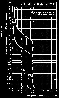
37 Circuit breaker construction Miniature Arc runners / Arc chutes The arc runner and arc chute limit and dissipate the arc energy during the interruption of an overload or short circuit event. During an overload or short circuit event, the contacts of the breaker separate and an electrical arc is formed between the contacts through air. The arc is moved into the arch chute by running the arc down the interior of the breaker along the arc runner. When the arc reaches the arc chute it is broken into small segmented arcs. The segmented arcs split the overall energy level into segments less than 25V. Each 25V segment does not have a high enough energy level to maintain an arc and all energy is naturally dissipated. Arc Runner Arc Chute Breaker curves Thermal Trip Unit (region one) The first sloping region of the breaker curve is a graphical representation of the tripping characteristics of the thermal trip unit. This portion of the curve is sloped due to the nature of the thermal trip unit. The trip unit bends to trip the breaker s trip bar in conjunction with a rise in amperage (temperature) over time. As the on the circuit increases, the temperature rises, the faster the thermal element will trip. Example using the curve below: If you had a 0A breaker and the circuit was producing 30 amps of, the breaker would trip between 2 seconds and minute. In this example you would find the circuit on the bottom of the graph (Multiples of rated ). The first line is 0 amps (0 amp breaker x a multiple of one), the second line is 20 amps (0 amp breaker x multiple of 2), and the third line is 30 amps (0amp breaker x multiple of 3). Next you would trace the vertical 30A line up until it intersects the red portion of the breaker thermal curve. If you follow the horizontal lines, on both sides of the red curve, to the left you will see that the breaker can trip as fast as 2 seconds and no slower than minute. Magnetic Trip Unit (region two) This region of the breaker curve is the instantaneous trip unit. ABB s miniature circuit breaker s instantaneous trip unit interrupts a short circuit in 2.3 to 2.5 milliseconds. Because of this the curve has no slope and is graphically represented as a vertical straight line. Example using the curve above: If you had a 0 amp breaker the magnetic trip element would interrupt a short circuit between 0 and 30 amps (0 amp breaker x multiple of 2 and 3) in 2.3 to 2.5 milliseconds. Breaker Contacts (region three) This region of the curve is the time required for the contacts of the breaker to begin to separate. The contacts will open in less than.5 milliseconds and is graphically represented by the bottom vertical portion of the curve. Thermal Trip Unit (Region One) Magnetic Trip Unit (Region Two) Moving Contacts (Region Three) Low Voltage Products & Systems.37
38 Miniature Circuit breaker limitation Current limiting definitions All ABB Miniature Circuit Breakers are UL tested and certified as limiting protective devices. Current limiting provide a higher level of circuit protection than a typical zero point external breakers. UL AC 60Hz cycle UL defines an AC cycle as the potential energy of the wave form traveling from Zero-to-Positive amplitude, Positive-to-Zero amplitude, Zero-to-Negative amplitude, Negative-to-Zero amplitude 60 times in one second. One cycle is completed every 6.6 milliseconds. UL breaker limiting UL defines breaker limitation as a breaker that interrupts and isolates a fault in less than /2 of an AC cycle. /2 a cycle is completed in 8.3 milliseconds. NEC240.2 limiting A device that, when interrupting in its -limiting range, reduces the flowing in the faulted circuit to a magnitude substantially less than that obtainable in the same circuit if the device were replaced with a solid conductor having comparable impedance. IEC limiting circuit breaker A circuit breaker with sufficiently short trip time to prevent the shortcircuit from reaching the peak value which would otherwise be reached. ABB limiting breakers ABB limiting breakers can interrupt and isolate a fault in /8 of an AC cycle. The breaker fault interruption is completed in 2.3 to 2.5 milliseconds. Zero point extinguishing breakers A typical zero point extinguishing breaker interrupts a fault and does not isolate the energy. The breaker allows an arc to be present between the open contacts until the AC wave form crosses zero. When the wave form crosses zero, the potential energy is zero and the arc (fault) naturally extinguishes. The arc could be present for up to 8.3 milliseconds. Current limiting breakers and electrical networks Current Limitation When a short-circuit condition occurs, the ideal limiting circuit breaker opens before the waveform can reach its full potential magnitude which occurs at ¼ cycle (4.7ms). ABB s limiting breakers can interrupt a fault in about ½ cycle or 2.3ms to 2.5ms. ABB s limiting breakers interrupt a short circuit in less than /8 cycle and limit the amount of that can reach a circuit. Limiting the available on the circuit provides additional protection against network, breaker, or bus damage and prevents the tripping of upstream breakers (selective coordination). IsqT The true destructive nature of a short circuit is measured by the time it is available combined with the peak value of the short circuit. The IsqT (Amps Squared over Time) value represents the amount of energy available on a network during a short circuit and is represented by the shaded area on the graph below. During a short circuit both magnetic forces and thermal energy combine to damage devices on the electrical network. The level of thermal energy and magnetic forces are directly proportional to the square of the. The magnetic forces vary as a square of the peak available and the thermal energy varies as a square of the RMS (root mean square) available. ABB s limiting breakers will limit the let-through energy to a fraction (/00 th ) of the value which is available from the network. By comparison, a Zero Crossing breaker would let-through approximately 00 times as much destructive energy as the limiting circuit breaker [ (00,000A / 0,000A) squared 00X]. ABB s limiting breakers limit the short circuit to a relatively small magnitude in a extremely short time, which dramatically limits a short circuit s destructive energy..38 Low Voltage Products & Systems

39 Circuit breaker limitation Miniature Current limiting and zero crossing breakers During the initial stages of a short circuit a breaker s contacts open to interrupt the circuit. After the contacts open an arc forms in the air between the contacts on both the limiting and zero crossing breaker contacts. What distinguishes a limiting breaker from a zero crossing breaker is what each breaker does after an arc is formed between the open contacts. Zero crossing example The test report below details a 20A Zero Point Extinguishing breaker interrupting a 9kA fault in 9 milliseconds. The total "I Square T" value is 04.0kA. 500 V 0 ka A limiting breaker runs the arc down the breaker arc runner into an arc chute that extinguishes the arc. A zero crossing breaker does not attempt to extinguish the arc. The breaker is designed to withstand the energy of the arc long enough for the waveform to cross zero. When the wave form crosses zero the potential energy is zero and the arc naturally extinguishes itself. ABB s limiting breakers interrupt the arc energy in 2.3ms to 2.5ms (/8 cycle) and a zero crossing breaker allows the arc to be present for up to 8.3ms (/2 cycle). A zero crossing breaker will let through 00 times as much energy as an ABB limiting breaker. Current limiting example The lab test report below details a 20A S200 series limiting breaker interrupting a 28kA fault in.7 milliseconds. The total I Square T value is 32.0kA U-BCP L2 00 /div I-L2 2 k/div Legend Voltage Amps 500 V 0 ka -500 Time A Time B Sample/div ksample U-L2 00 /div I-L2 2 k/div Legend Voltage Amps -500 Time A Time B Sample/div ksample Low Voltage Products & Systems.39

. When there is no breaker coordination several circuits lose power that should remain operational during and after the overload event.")
40 Miniature Selective coordination and series ratings IEC selective coordination definition Coordination between the operating characteristics of two or more over- protection devices, so that when an over- within established limits occurs, the device designated to operate within those limits trips whereas the other do not trip. Main breaker Example of no breaker coordination Selective breaker coordination is not achieved when there is an overload event at the branch breaker level (MCB) and both the branch breaker and main breaker interrupt the circuit (open). When there is no breaker coordination several circuits lose power that should remain operational during and after the overload event. The chart below gives a graphical representation of a down stream branch breaker (B curve) and a main breaker (A curve) without coordination. There is no separation between the curves. The branch breaker will react to a fault and the main breaker will open and de-energize all circuits down stream. CB CB2 CB3 CB4 Short circuit Example of breaker coordination When an over- event occurs at the branch breaker level (CB), and the event is within the operating characteristics of the breaker, then the branch breaker should interrupt the circuit (open) and the main breaker should remain closed and energized. The chart below gives a graphical representation of a down stream branch breaker (B curve) and a main breaker (A curve) with coordination. The separation between the curves allows the branch breaker to react to the fault and the main breaker remain closed and energized. Problems in coordination occur when the branch breaker allows the "I Square T" value of the short circuit to rise to a level that is in the operating range of the up-stream main breaker. Proper breaker coordination is easier to achieve with the use of limiting breakers at the branch level. Selective coordination and limiting breakers Recent improvements in ABB circuit breaker technology has pushed the performance of breakers to the same level as fuses. The reaction time and tripping characteristics of limiting breakers are now on par with fuses. This allows ABB to provide a high level of coordination between branch breakers and the main. A limiting branch breaker will limit the I Square T value well below the level of the operating range of the up-stream main breaker. ABB s limiting branch breakers can coordinate between the main breaker up to 35kA. Selective coordination and zero crossing breakers Zero crossing breakers do not limit the I Square T value. They wait for the wave form to cross zero and allow a high level of let-through energy to pass through the system. The I Square T value of a zero crossing breaker is high enough that the main breaker will likely trip during a short circuit. With zero crossing breakers it is extremely difficult to coordinate between branch and main breakers. A typical zero crossing breaker s coordination level is below 0kA. There are a few manufactures that have achieved coordination between a branch zero crossing breaker and the main by slowing the performance (protection) of the main breaker..40 Low Voltage Products & Systems
41 Selective coordination and series ratings Miniature Series ratings vs- selective coordination Selective coordination Selective coordination is achieved when there is a short circuit on a branch circuit breaker, the branch breaker opens and isolates the fault, and the main breaker remains closed. The rating is usually a value above the stand alone interrupting rating of the branch breaker and the stand alone rating of the main breaker. Example: 65kA rated main breaker 0kA rated branch breaker Coordination between the two breakers up to 35kA There can be a short circuit on the branch breaker up to 35kA where the branch will open (CB) and the main breaker will remain closed. Although the branch has a 0kA stand alone rating both the breakers work together to limit the available short circuit to allow the branch (CB) to isolate the fault. Main breaker 65 ka Series ratings Series ratings are different from coordination ratings. Unlike coordination ratings where the branch opens and the main remains closed, a series rated combination is one where both the branch and main breakers open and work together to isolate the fault. The series rating combination of two breakers is equal to the stand alone interrupting value of the main breaker. This is a result of the main breaker let-through value being lower than the stand alone interrupting value of the branch breaker. During a short circuit the main breaker will limit the energy to a level that is below the stand alone value of the branch breaker. Example: 65kA rated main breaker 0kA rated branch breaker Series combination rating between the two breakers up to 65kA There can be a short circuit on the branch breaker up to 65kA where the branch will open and the main breaker will open. Although the branch breaker (CB) has a 0kA stand alone rating the main breaker has a let-through value below 0kA. If there is a fault up to 65kA on the network the main breaker will limit the energy to a value less than the rating of the branch breaker (CB). Both breakers will trip (no coordination) but the network can safely withstand a fault of 65kA. CB 0 ka CB2 0 ka CB3 0 ka CB4 0 ka 35 ka or 65 ka short circuit Low Voltage Products & Systems.4

42 Miniature Miniature circuit breaker cutaway Tripping lever Electro-magnetic protection Upper terminal Operating mechanism Thermal protection-bimetal Operator Arc chamber Space for identification marker Fixed contact Moving contact Lower terminal DIN rail clip.42 Low Voltage Products & Systems
S200 UL 1077 Series S200. Supplementary protective devices. UL 1077 Series. Miniature. circuit breakers. S200 Supplementary protective devices
 UL 077 Series Supplementary protective devices The UL 077 Series miniature supplementary protector offers a compact solution for protection requirements. The devices are DIN rail mounted. The is available
Miniature circuit breaker Application guide
 Miniature circuit breaker Application guide Miniature Miniature circuit circuit breakers breakers Application S200 guide Introduction The circuit breaker plays an important role in providing over-current
S200 UL 489 Series. Miniature circuit breakers S200. Features. Description
 UL 489 Series UL 489 Series Description The Series miniature circuit breaker offers a compact solution for protection requirements. The U AND UP devices are UL 489 tested limiting and DIN rail mounted.
S200-C, 480Y/277 VAC Supplemental protectors UL 1077, CSA 22.2
 S00-C, 480Y/77 VAC UL 077, CSA. Miniature C S0-C S0-C S03-C S04-C S0-CNA + NA 0.5 S0-C0.5 0.5 S03-C0.5 S0-C S03-C.6 S0-C.6.6 S03-C.6 S0-C S03-C 3 S0-C3 3 S03-C3 4 S0-C4 4 S03-C4 6 S0-C6 6 S03-C6 8 S0-C8
Miniature Circuit Breaker UL / CSA Range
 PRODUCT CATALOG CANADA Miniature Circuit Breaker UL / CSA Range UL489 / CSA C22.2 No.5 devices UL1077 / CSA C22.2 No. 235 devices Electronic Protection Devices Technical data Miniature Circuit Breakers
US CATALOG. Miniature circuit breakers
 US CATALOG Miniature circuit breakers Table of contents 004 024 S(U)200 series miniature circuit breakers UL 489 series 025 048 S200 series miniature circuit breakers UL 1077 series 049 056 Application
US CATALOG. Miniature Circuit Breakers
 US CATALOG Miniature Circuit Breakers Miniature circuit breakers Table of contents S(U)200 series miniature circuit breakers UL 489 series Description and features 2 SU200M-C 3 SU200M-K 4 SU200M-Z 5 SU200MR-K
Miniature Circuit Breakers
 S00 Series Miniature S00 Series Miniature Circuit Breakers Description The S00 Series miniature circuit breaker offers a compact solution for protection requirements. The S00 devices are UL tested limiting
MCBs and accessories are certified under CSA C22.2 No. 235 per File LR Tripping characteristics
 Miniature circuit breakers General information General information Miniature circuit breakers (MCBs) are used throughout the world in all types of electrical installations. ABB MCBs are recognized for
The breakers offer thermal-magnetic trip protection according to Z and K characteristics.
 Series High Performance Circuit Breakers Description The high performance MCB offers a compact solution to circuit protection. The devices are DIN rail mounted. The is available with application-specific
Pro M Miniature Circuit Breakers S260, S270, S280, S290. System Pro M. Description
 Miniature Circuit Breakers S260, S270, S280, S290 Description The S2 Series of miniature circuit breakers offer a compact solution to protection requirements. The breakers are recognized under standard
Accessories SU200M, SU200MR, and S200UDC UL 489, CSA 22.2 No. 5
 Auxiliary contacts The auxiliary contacts will signal whether the breaker is in the ON or OFF position. For field mounting: right side SC-HRU SC-HRU Bell alarm The bell alarm includes a set of contacts
Control Circuit Protection
 Contents 5SJ4 Branch Circuit Protectors 5SY4 Supplementary Protectors 5SY6 Supplementary Protectors 16/19 5SJ4 Page Selection and ordering data 1-pole up to 63A 16/4 1-pole, 2-pole, 16/5 3-pole, 240VAC
Jtec 10kA Miniature Circuit Breaker
 EN 60898 Jtec 10kA Miniature Circuit Breaker Techna s JTEC range has been enthusiastically adopted by a diverse range of customers seeking a cost effective 10kA performance. Jtec MCBs are available in
Series L9 UL-489 Miniature Circuit Breakers
 Series UL-489 iniature Breakers Industrial Breakers for Branch up to 40 Amps Sprecher+Schuh includes a line of circuit breakers approved for branch circuit applications in the United States and Canada
Technical Data. Miniature circuit-breakers for branch circuit protection according to UL 489, CSA C 22.2 No. 5
 Technical Data Miniature circuit-breakers for branch circuit protection according to UL 489, CSA C 22.2 No. 5 When connecting aluminum conductors, ensure that the contact surfaces of the conductors are
MCBs S260 S290. Pro M Miniature Circuit Breakers S260, S270, S280, S290. System Pro M. Description. Features
 Miniature Circuit Breakers S260, S270, S280, S290 S260 S290 MCBs Description The S2 Series of miniature circuit breakers offer a compact solution to protection requirements. The breakers are recognized
Bulletin 1489 Circuit Breakers. Selection Guide
 Bulletin 1489 s Selection Guide Bulletin 1489-A Overview/Description Bulletin 1489-A s Energy-limiting design protects downstream components better than conventional breakers during short circuits Field-mountable
1492-CB 1492-GH 1492-GS
 1 The Allen-Bradley Line of Devices Allen-Bradley offers 3 different lines of Circuit Breakers (Supplementary Protectors) and a line of branch circuit rated Fuse Holders. Allen-Bradley Thermal Magnetic
Series L9 UL489 Miniature Circuit Breakers
 Series L9 UL489 iniature Circuit Breakers Industrial Circuit Breakers for Branch Circuit Protection up to 63 Amps L9 Series B Circuit Breakers Series B L9 UL489 circuit breakers offer new features, expanded
1489-M Circuit Breakers
 Dual terminals provide wiring/bus bar flexibility and clamp from both sides to improve connection reliability Terminal design helps prevent wiring misses Scratch- and solventresistant printing Suitable
System pro M compact Miniature Circuit Breaker SU200M for branch circuit protection acc. to UL 489
 System pro M compact Miniature Circuit Breaker SU200M for branch circuit protection acc. to UL 489 2CDC021004S0014 2CDC021046S0014 The miniature circuit breaker SU 200 M is ABB s solution for UL 489 branch
SU200M Datasheet. Branch protection acc. to CSA C22.2 No.5 / UL 489
 MINIATURE CIRCUIT BREAKERS SU200M Datasheet Branch protection acc. to CSA C22.2 No.5 / UL 489 The miniature circuit breaker SU200 M is ABB s solution for UL 489 branch circuit protection up to 480 Y/277
System pro M compact Miniature Circuit Br eakers Description Features
 System pro M compact Miniature Circuit reakers S0 Series Description Increasing energy requirements result in larger short-circuit currents which place heavy demands on protective switchgear regarding
System pro M compact Miniature Circuit Breaker SU200 M for branch circuit protection acc. to UL 489
 Data Sheet System pro M compact for branch circuit protection acc. to UL 489 2CDC021004S0014 2CDC021046S0014 The miniature circuit breaker SU200 M is BB s solution for UL 489 branch circuit protection
Product Line Overview. The Most Logically Designed Contact Assembly
 Circuit Breakers & Supplementary Protectors 15 00 Amperes for UL, CSA & IEC Applications Product Line Overview -3 General Information Cutler-Hammer Series G Molded Case Circuit Breakers provide increased
Manual motor protectors Type MS116 Type MS325 Type MS45X Type MS49X
 Manual motor protectors Type MS116 Type MS32 Type MS4X Type MS49X Manual motor protectors MS116 MS32 MS4X MS49X Description Type MS116 Suitable for use with 3-phase motors up to 10 HP @ 480V UL ed and
Protectors. 35mm DIN rail snap-on mounting. Wide range of accessories
 Manual motor protectors Manual motor protectors Manual motor Protectors MS116 MS32 MS4X MS49X Description Type MS116 Suitable for use with 3-phase motors up to 10 HP @ 480V UL Listed and CSA certified
Miniature Circuit-Breakers (MCBs)
") Product Overview Miniature Circuit-Breakers (MCBs) Design Tripping characteristics Rated current I n Rated breaking capacity Power supply company product range 5SP3 E 16 - A Standard product range 5SQ2
Product Overview Miniature Circuit-Breakers (MCBs) Design Tripping characteristics Rated current I n Rated breaking capacity Power supply company product range 5SP3 E 16 - A Standard product range 5SQ2
UMBW-UL489 and UL1077 Listed
 -UL489 and UL77 Listed Introducing the New WEG Series Thermal-Magnetic Miniature Breakers. This new offering includes both UL489 and UL77 approvals to provide a solution for circuit & equipment protection
Product index. 4 - Manual motor protectors. Manual motor protectors. Manual motor protectors Low Voltage Products & Systems 4.
 Product index -....1.3 Features and benefits...1 General information Suitable applications...2 -.3 Motor ratings... Pilot duty ratings and overload trip classes...5 Ordering details Type MS116...6 Type
Product index. 4 - Manual motor protectors. Phone: Fax: Web: -
 Product index -....1.3 Features and benefits...1 General information Suitable applications...2 -.3 Motor ratings... Pilot duty ratings and overload trip classes...5 Ordering details Type MS116...6 Type
and other modular devices for low voltage installation
 Technical catalogue System and other modular devices for low voltage installation 2CSC400002D0204 SUMMARY Introduction Miniature Circuit-Breakers Residual Current Devices Auxiliary elements and accessories
System pro M compact Supplementary protector S 200 PR for ring-tongue applications acc. to UL1077
 Data Sheet System pro M compact Supplementary protector S 200 PR for ring-tongue applications acc. to UL1077 2CDC021026S0011 2CDC021016S0012 The S 200 PR is a high-performance supplementary protector with
MULTI 9 System Catalog IEC Rated C60N/H/L Circuit Breakers
 IEC Rated C60N/H/L Circuit Breakers Standard Features Fast Closing Allows increased withstand to the high inrush currents of some loads Trip-free mechanism: Contacts cannot be held in the on position when
Interchangeable Built-in Fixed thermal Adjustable thermal Magnetic Fixed Adjustable Adjustable Electronic RMS 7 LS LSI
 . Technical Data and Specifications Ratings Frames EG, JG and LG EG JG LG Maximum rated current (amperes) 15, 160 1 50 400, 630 Breaker type 3 B B E S S H H C E S H C U X E S H C U X of poles 1, 3, 4,
Page. Circuit-Breakers M4 2 for motor protection. Auxiliary contacts 3 Signalling switch Auxiliary releases
 Circuit Breakers M4 Page Circuit-Breakers M4 2 for motor protection Auxiliary contacts 3 Signalling switch Auxiliary releases Insulated 3-pole busbar system 4 Terminal block DIN-rail adapters 5 Busbar
Series KTU7 UL489 Molded Case Circuit Breakers
 Series UL489 Molded Case Circuit Breakers Versatile, convenient and space saving for a variety of applications Sprecher+Schuh s series of UL are UL489 and CE listed for global applications. The current
Manual motor protectors Type MS116 Type MS325 Type MS45X Type MS49X
 Manual motor protectors Type MS116 Type MS32 Type MS4X Type MS49X Manual motor protectors Description Type MS116 Suitable for use with 3-phase motors up to 10 HP @ 480V UL Listed and CSA certifi ed for
System pro M compact Miniature Circuit Breaker S 200 M UC for DC and AC applications
 Data Sheet System pro M compact Miniature Circuit Breaker S 200 M UC for DC and AC applications 2CDC021031S0011 2CDC021033S0011 The miniature circuit breaker S 200 M UC extends the established ABB System
System pro M compact Miniature Circuit Breaker S 200 M UC for DC and AC applications
 System pro M compact Miniature Circuit Breaker S 200 M UC for DC and AC applications 2CDC021031S0011 2CDC021033S0011 The miniature circuit breaker S 200 M UC extends the established ABB System pro M compact
Selection Guide. Control Circuit and Load Protection
 Selection Guide Control Circuit and Load Protection Circuit Protection Portfolio 1489-M Circuit Breakers Approved for branch circuit protection in the United States and Canada, and certified as Miniature
Series KTU7 UL489 Molded Case Circuit Breakers
 Series KTU7 UL489 Molded Case Circuit Breakers Versatile, convenient and space saving for a variety of applications Sprecher+Schuh s KTU7 series of UL Molded Case Circuit Breakers are UL489 and CE listed
Tmax Molded Case Circuit Breakers
 Tmax Molded Case Circuit s Introduction ABB is once again demonstrating its commitment to new product development and its superiority in product technology. Never before has the industry seen such high
3 - Protection components Motor circuit-breakers
 Contents 0 - Protection components Motor circuit-breakers protection components for the motor protection Thermal-magnetic motor circuit-breakers Selection guide..............................................page
Circuit-Breakers M4 166 for motor protection. Auxiliary contacts 167 Signalling switch Auxiliary releases
 Index Page Circuit-Breakers M4 166 for motor protection Auxiliary contacts 167 Signalling switch Auxiliary releases Insulated 3-pole busbar system 168 Terminal block DIN-rail adapters 169 Busbar adapters
Protectors. Manual motor. Types MS116, MS132, MS45x, MS49x. MS Series. Manual motor protectors. Type MS116. Type MS132. Type MS45x.
 Types MS116, MS132, MS5x, MS9x are electromechanical devices for motor and circuit protection. These devices offer local motor disconnect means, manual ON/OFF control, and protection against short circuit,
Technical data for manual motor starters Type MS325
 for manual mor starters Type MS325 General data Rated voltage 600 V Rated current 25 A (14 setting ranges, 0.1 25A) Rated frequency 50-60 Hz Electrical and mechanical life endurance 100,000 operations
AF09... AF30 3-pole Contactors up to 25 HP / 600 VAC
 AF09... AF0 -pole Contactors up to 25 HP / 600 VAC Contactors and Overload Relays Overview.../0 AF09... AF0 -pole Contactors.../2 Main Technical Data.../8 Main Accessory Fitting Details.../2 Main Accessory.../24
MINIATURE CIRCUIT BREAKERS RCBO s & DIN RAIL MOUNTED FUSE HOLDERS
 MINIATURE CIRCUIT BREAKERS RCBO s & DIN RAIL MOUNTED FUSE HOLDERS MANUFACTURED IN THE EU EUROPEAN QUALITY 1, 2 & 3 POLE MCB s TRIPPING CURVES C & D CURRENT RATINGS 1AMP TO 63AMPS 10KA BREAKING CAPACITY
Miniature Circuit Breaker
 Introduction - Miniature Circuit Breaker (MCB) SALIENT FEATURES SALIENT FEATURES Standards MCBs conform to the latest standard IS 8828: 1996/IEC: 898 1995 Mid-Trip Position The Mid trip position of the
GJL 100 A Molded Case Circuit Breaker GJL 75 A Motor Circuit Protector
 GJL 100 A Molded Case Circuit Breaker GJL 75 A Motor Circuit Protector Catalog 0500CT9702R409 2009 Class 525/580 CONTENTS Description............................................. Page General Characteristics...................................
Circuit Breakers. Excerpt from Master Catalogue. Circuit Breakers. Specifically For You
 Circuit Breakers Specifically For You Excerpt from Master Catalogue Circuit Breakers DIN rail mount, thermal/magnetic circuit breakers. Their compact dimensions, ease of mounting and excellent performance
PRICING. Multi 9, Compact, Masterpact, Interpact, and Vigirex Circuit Protection Products. Class 600. October 2004
 PRICING October 2004 Multi 9, Compact, Masterpact, Interpact, and Vigirex Circuit Protection Products Class 600 CONTENTS Description Page Multi 9 Supplementary Protectors and Miniature Circuit Breakers.............3
Typical UL1077 Application
 Altech UL77 Typical UL77 Application Control Circuit of a UL508A Panel Disclaimer: This is just an example application. Installation should be done by a qualified electrician under the guidance of UL/NEC
MS /27/2015. ABB contact for United States of America. General Information Extended Product Type: Categories
 Page 1 of 5 MS132-10 ABB contact for United States of America General Information Extended Product Type: Product ID: EAN: Catalog Description: Long Description: MS132-10 1SAM350000R1010 4013614400100 MS132-10
BR/SUxxxUC Series UL 489 and UL 1077 AC/DC Rated Miniature Circuit Breakers
 BR/SUxxxUC Series UL 489 and UL 077 AC/DC Rated Miniature Circuit Breakers Application Schematic G L L L3 Power Circuit UL489 BRxxUC UL489 BR3xxUC Control Circuit Power Circuit UL489 BRxxUC Power Transformer
Technical data. Miniature Circuit Breakers. System pro M. System pro M
 Technical data System pro M System pro M 1 Prior to connection of aluminium conductors ensure that their contact points are cleaned, brushed and coated with grease. The contact terminals must be tighten
ELFA E90S MINI BREAKERS
 ELFA E90S MINI BREAKERS ELFA E90S SERIES UL Approved (UL1077) 10KA INTERUPTION CAPACITY OPTIONS FIELD KITS Auxiliary Contacts Alarm Contact Shunt Trip UV Trip Current Limiting Design (Class 3) 3 Different
Reduced Voltage Motor Starters
 Reduced Voltage Motor Starters Soft Start Controllers. Solid-State Controllers Product Overview........................................ Type S70, Soft Start Controllers............................. Type
Table Line and Load Terminals. Terminal Body Material. Wire Type. Aluminum Copper Aluminum. English English English.
 -174 Series C Molded Case Circuit s July 7 Molded Case Switches Refer to Eaton for UL listed, series tested Molded Case Switch application data. Table -278. Molded Case Switches Cont. Amp Rating at 40
XT IEC Power Control Manual Motor Protectors
 May 07 Product Selection Table 7. Rotary with Screw Terminals Global Ratings and North American Ratings Type and Type 2 Coordination Motor Protective Device with Thermal and Magnetic Trip Rated Uninterrupted
The new SH200 MCBs can be used in domestic, commercial and industrial applications for protection against over-current and short circuit.
 s Product Overview SH200 The new SH200 s can be used in domestic, commercial and industrial applications for protection against over-current and short circuit. New Enhancement Optimized connection terminal
Control Circuit of a UL508A Panel. Typical UL1077 Application
 Altech UL077 Typical UL077 Application Control Circuit of a UL508A Panel Disclaimer: This is an example application. Installation should be done by a qualified electrician under the guidance of UL/NEC
Miniature Circuit-Breakers (MCBs)
") Product overview Miniature Circuit-Breakers (MCBs) Design Tripping characteristic Rated currents I n Rated breaking capacity Power supply company product range 5SP3 E 16 - A Standard product range 5SX2
Product overview Miniature Circuit-Breakers (MCBs) Design Tripping characteristic Rated currents I n Rated breaking capacity Power supply company product range 5SP3 E 16 - A Standard product range 5SX2
Protection Equipment. 5/2 Introduction
 Protection Equipment /2 Introduction SIRIUS 3RV2 Motor Starter Protectors/ Circuit Breakers up to 40 A /6 General data /12 For motor protection /14 For motor protection with overload relay function /1
www. ElectricalPartManuals. com Miniature Circuit Breakers Section 7
 EP60 Series...7-2 EP100 Series...7-4 EP100 ULH Series...7-6 EP100 UC Series (Branch Circuit Protection)...7-8 Series CA Auxiliary Switch and Bell Alarm...7-10 Series CB Auxiliary Switch and Bell Alarm...7-11
1.1. Contactors and Starters... Contents Description Relays and Timers... Miniature Controls... Manual Motor Protectors. XT IEC Power Control
 . Contents Description Relays and Timers......................... Miniature Controls......................... Contactors and Starters.................... Thermal Relays.................... C440/XT Electronic
Motor-protectivecircuit-breaker,3p,Ir=2.5-4A. Product range PKZM01 motor protective circuit-breakers up to 16 A with pushbutton actuation
 Motor-protectivecircuit-breaker,3p,Ir=2.5-4A Partno. PKZM01-4 Articleno. 278482 CatalogNo. XTPB004BC1 Deliveryprogramme Product range PKZM01 motor protective circuit-breakers up to 16 A with pushbutton
Jtec 489 UL489 Branch Circuit Breaker
 Jtec 489 UL489 Branch Circuit Breaker 10kA Miniature Circuit Breaker R The Jtec 489 range is UL 489 listed (File E255530). Available in trip curves Z (v. quick), B (quick), C (medium), K (motor) and D
Protection Equipment
 Protection Equipment Price Groups 101, 102, 121, 131, 143 /2 Introduction Motor Starter Protectors/ Circuit Breakers SIRIUS 3RV2 Motor Starter Protectors up to 40 A new /7 General data /13 For motor protection
LPCC3 3A 600V TD Class CC Low Peak Fuse. Features amperage rating. Dimensions and Weight. Long Description. Manufacturer Information
 3804 South Street 75964-7263, TX Nacogdoches Phone: 936-569-794 Fax: 936-560-4685 LPCC3 3A 600V TD Class CC Low Peak Fuse Catalog Number Manufacturer Description Weight per unit Product Category LPCC3
smissline Description
 Modular power distribution bus system Description The power distribution bus system provides a versatile and flexible means of distributing power to a wide variety of electrical devices. Ideal for group
AF40... AF96 3-pole contactors Technical data
 Main pole - Utilization characteristics according to IEC Standards IEC 60947- / 60947-4- and EN 60947- / 60947-4- Rated operational voltage Ue max. 690 V Rated frequency (without derating) 50 / 60 Hz Conventional
Circuit Protection. Circiut Protection
 Circuit Protection Series L8 UL1077 Supplementary Protectors...2 Selection Guide - Trip Curve "B"...4 Selection Guide - Trip Curve "C"...5 Selection Guide - Trip Curve "D"...6 Accessories...7 Technical
Technical Information
 -100 Controller IEC Performance Data (CSA C22.2, UL 508 No. 14 in connection with a short-circuit protection device Catalog No. -100... 25A 40A 63A 90A Maximum Short-Circuit Current 480V [ka] 65 65 42
Low-Peak 600V Class RK1
 LPS-RK 600Vac/300Vdc, 1 10-60A, Dual Element, Time-Delay Fuses Dimensions - in 5" (± 0.31) 5.5" (± 0.31) Available with easyid open fuse indication 1/10 to 30A 0.81" (±0.008) 35 to 60A 1.06" (±0.008) Description:
1.1. Contactors and Starters... Contents Description Relays and Timers... Miniature Controls... Manual Motor Protectors. XT IEC Power Control
 Contents Description Relays and Timers......................... Miniature Controls......................... Contactors and Starters.................... Thermal Overload Relays.................... C440/XT
FMotor Circuit Controllers
 Technical Information Motor Circuit Controller IEC Performance Data Catalog Number KTA7-25S...32S 0.16A 0.25A 0.4A 0.63A 1A 1.6A 2.5A 4A 6.3A 10A 16A 20A 25A 29A 32A Rated Operational Current, I e [A]
BETA Switching Switches and Light Indicators
 Siemens AG 2008 BETA Switching /2 Product overview /3 5TE8 control switches / 5TE4 pushbuttons /2 5TE5 light indicators /5 5TE8 ON/OFF switches /22 5TE9 busbars /24 5TE switch disconnectors Siemens ET
Proline Panelboard and breakers
 Proline Panelboard and breakers ProLine & breakers ProLine The ProLine is the electrical industry's first limiting, touch safe, fully coordinated UL 67. Electrical: UL File #E319800 UL67 225A and 400A
MINIATURE CIRCUIT BREAKER
 Technical Article MINIATURE CIRCUIT BREAKER T 146 PURCHASE he Spaceage MCB protects wires and cables automatically against overload and short-circuits in domestic, commercial and industrial installations.
AF series contactors (9 2650)
") R E32527 R E39322 contactors General purpose and motor applications AF series contactors (9 2650) 3- & 4-pole contactors General purpose up to 2700 A Motor applications up to 50 hp, 900 kw NEMA Sizes 00
R E32527 R E39322 contactors General purpose and motor applications AF series contactors (9 2650) 3- & 4-pole contactors General purpose up to 2700 A Motor applications up to 50 hp, 900 kw NEMA Sizes 00
G-Series. Circuit Breaker.
 -Series Circuit Breaker Carling Technologies -Series hydraulic/magnetic circuit breakers offer the highest quality solution to your circuit protection requirements. The -Series is designed to sense over-current
NB1 Miniature Circuit Breaker
 P-00 Modular DIN Rail Products MCB NB Miniature Circuit Breaker Color coded contact position indicator provides visual indication of the device status and insulation function Magnetic trip elements provide
Short form catalogue. Motor protection & control
 Short form catalogue Star Series Motor protection & control Motor Protection and Control up to 25 HP / 600 VAC Overview...2 Contactors and Overload Relays...11 4-pole Contactors...41 Control Relays...59
Fuse holders and fuses
 Modular size for 10x38, 14x51 and 22x58mm fuses Finger safe - IEC IP20 degree of protection against accidental contact with live parts and with sealable cover for operators safety Version with status indicator
ECET Distribution System Protection. Overcurrent Protection
 ECET 4520 Industrial Distribution Systems, Illumination, and the NEC Distribution System Protection Overcurrent Protection One of the most important aspects of distribution system design is system protection.
Page 12-2 Page Page Page DC FUSES FOR PHOTOVOLTAIC APPLICATIONS 10x38mm, IEC class gpv Rated current: 20A Rated voltage: 1000VDC.
 Page -2 Page -2 AC FUSE HOLDERS Version without indicator: 1P, 1P+N, 2P, 3P, 3P+N Version with indicator: 1P For fuses x38, 14x51 and 22x58mm IEC class gg or am. IEC rated current: 32A, 50A, 0A IEC rated
max pole for t=15 ms
 Types RI 61 RI 61N RI 61J RI 62 RI 62J RI 63 RI 63N RI 64 single-pole single-pole + neutral pole single-pole (for DC circuits) two-pole two-pole (for DC circuits) three-pole three-pole + neutral pole three-pole
Manual Motor Starters. Meta-MEC
 Manual Motor Starters Meta-MEC Manual Motor Starters LS Meta-MEC Manual Motor Starters provide completed ranges up to 100A 45 mm 55 mm 32AF 2 2 45 mm 70 mm 63AF 100AF 3 3 Manual LS Meta-MEC Motor Starters
Uncompromising safety and comfort Miniature Circuit Breaker SU 200 M for branch circuit protection per UL and CSA
 Uncompromising safety and comfort Miniature Circuit Breaker SU 200 M for branch circuit protection per UL and CSA The next generation MCB for UL/CSA applications within the proven System pro M compact
AF series contactors (9 2650)
") R E32527 R E39322 contactors General purpose and motor applications AF series contactors (9 2650) 3- & 4-pole contactors General purpose up to 2700 A Motor applications up to 50 hp, 900 kw NEMA Sizes 00
R E32527 R E39322 contactors General purpose and motor applications AF series contactors (9 2650) 3- & 4-pole contactors General purpose up to 2700 A Motor applications up to 50 hp, 900 kw NEMA Sizes 00
(Miniature Circuit Breaker)
") (Miniature Circuit Breaker) Features : l Uniform 10KA breaking capacity for B and C Curve l Low power consumption, thus cost effective & energy saving l Suitable for DC and for a wide frequency range of
(Miniature Circuit Breaker) Features : l Uniform 10KA breaking capacity for B and C Curve l Low power consumption, thus cost effective & energy saving l Suitable for DC and for a wide frequency range of
LPSRK30SP 30A 600V TD Dual Elem Class RK1 Low Peak Fuse
 LPSRK30SP 30A 600V TD Dual Elem Class RK Low Peak Fuse Catalog Number Manufacturer Description Weight per unit Product Category LPSRK30SP 30A 600V Class RK Low Peak Dual Element, Time Delay Fuse 600 (lbs/each)
Characteristics of LV circuit breakers Releases, tripping curves, and limitation
 Characteristics of LV circuit breakers Releases, tripping curves, and limitation Make, Withstand & Break Currents A circuit breaker is both a circuit-breaking device that can make, withstand and break
Section Contents. Disconnect Switches
 Section Contents Page Compact Circuit Protector (CCP) fused disconnect switches....................326-329 Fused, dead front disconnect switches...........329 Fusible Disconnect Switch Overview............330
E s h o r t c ir c u it Wit h s t AND r At ing s f o r r -s er ies s u ppl ement Ar y pr o t ec t o r
 UR-Series UL077 Recognized Supplementary Protector DIN Rail Mounted 7.5mm width per pole Thermal Magnetic 80Y/277V AC, 50/Hz 0kA Short Circuit Withstand Capacity Applications (on the load side of Branch
MS General Information Extended Product Type: MS
 MS132-1.6 General Information Extended Product Type: MS132-1.6 Product ID: 1SAM350000R1006 EAN: 4013614400063 Catalog Description: MS132-1.6 Manual Motor Starter Long Description: The MS132-1.6 manual
ACW. Molded-Case Circuit Breaker UL 489 Listed. ACW Catalog Number Sequence
 rotection rotectors Contactors Overloads Relays ushbuttons Molded-Case Breaker UL 489 Listed The EG Series of Molded Case Breakers are designed to provide overload and short-circuit protection for industrial