US CATALOG. Miniature Circuit Breakers
|
|
|
- Mervin Jackson
- 6 years ago
- Views:
Transcription

1 US CATALOG Miniature Circuit Breakers
2
3 Miniature circuit breakers Table of contents S(U)200 series miniature circuit breakers UL 489 series Description and features 2 SU200M-C 3 SU200M-K 4 SU200M-Z 5 SU200MR-K 6 S200UDC-K 7 S200UDC-Z 8 Accessories 9 Technical specifications 16 Dimensions 22 S800U series miniature circuit breakers UL 489 series Description and features 54 S800U-K 55 S800U-Z 56 S804U-PVS5 57 S804U-UCZ 59 S803W-SCL-SR UL Short circuit current limiter 61 S800W-RSU Remote switching unit 63 Accessories 64 Technical specifications 66 Dimensions 70 S200 series miniature circuit breakers UL 1077 series Description and features 23 S200-B 24 S200-C 25 S200-D 26 S200-K 27 S200-Z 28 S200P-B 29 S200P-C 30 S200P-D 31 S200P-K 32 S200P-Z 33 S200MR-K 34 S200MUC-C 35 S200MUC-K 36 S200MUC-Z 37 Accessories 38 Technical specifications 42 S200MUC uses 44 Dimensions 45 Application guide Introduction, overload, short circuit, breaker definition 46 Circuit breaker construction 47 Circuit breaker current limitation 49 Selective coordination and series ratings 51 Miniature circuit breaker cutaway 53 S800C series miniature circuit breakers UL 1077 series Description and features 72 S800C-B Characteristic B 73 S800C-C Characteristic C 74 S800C-D Characteristic D 75 S800C-K Characteristic K 76 Technical specifications 77 Dimensions 78 S500 series miniature circuit breakers UL 1077 series Description and features 79 S500-K 80 S500UC-B 81 S500UC-K 82 Accessories 83 Technical specifications 84 Dimensions 85 EPD24 Electronic Protection Device EPD24-TB Ordering information 87 US Catalog Miniature Circuit Breakers 1

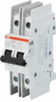
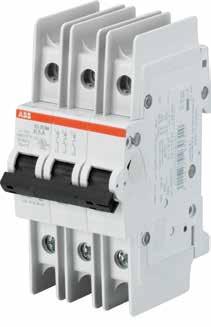
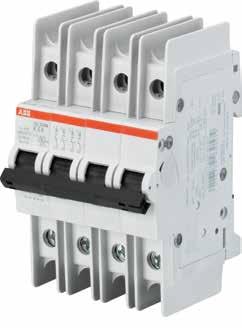
4 S(U)200 series SU200M, SU200MR, and S200UDC UL 489 series Description The SU200M, SU200MR, and S200UDC miniature circuit breakers offer a compact solution for protection requirements. The SU200 series devices are current-limiting according to UL 489 and DIN rail mounted. SU200M, SU200MR, and S200UDC MCBs come in up to 3 trip curves to provide maximum circuit protection. For the worldwide market, the breakers carry UL, CSA, IEC, CE and many other agency approvals and certifications. Features UL current limiting Fast breaking time ( ms) Bus connection system Wide range of accessories Available with variable depth handle mechanism CE certified and marked DIN rail mounting Finger safe terminals Multi-function terminals Suitable for reverse feed (except for S200UDC) UL 489 Listed - branch circuit protective device UL File #E SU200M SU200MR S200UDC Amperage Voltage up to 277/Y480 VAC 48/96 VDC up to 277/480 VAC Trip curves Z, C, K K Z, K Interrupt rating 10 ka- 10 ka 14 ka Auxiliary contacts Yes Yes Yes Bell alarm Yes Yes Yes Shunt trip Yes Yes Yes Busbar Yes Yes Yes 60/125 VDC 2 Miniature Circuit Breakers US Catalog
5 SU200M-C Branch circuit protection UL 489, CSA 22.2 No. 5 Number of poles 1 2 A Number of poles A 0.5 SU201M-C SU203M-C0.5 1 SU201M-C1 1 SU203M-C1 1.6 SU201M-C SU203M-C1.6 2 SU201M-C2 2 SU203M-C2 3 SU201M-C3 3 SU203M-C3 4 SU201M-C4 4 SU203M-C4 5 SU201M-C5 5 SU203M-C5 6 SU201M-C6 6 SU203M-C6 7 SU201M-C7 7 SU203M-C7 8 SU201M-C8 8 SU203M-C8 10 SU201M-C10 10 SU203M-C10 13 SU201M-C SU203M-C13 15 SU201M-C15 15 SU203M-C15 16 SU201M-C16 16 SU203M-C16 20 SU201M-C20 20 SU203M-C20 25 SU201M-C25 25 SU203M-C25 30 SU201M-C30 30 SU203M-C30 32 SU201M-C32 32 SU203M-C32 35 SU201M-C35 35 SU203M-C35 40 SU201M-C40 40 SU203M-C40 50 SU201M-C50 50 SU203M-C50 60 SU201M-C60 60 SU203M-C60 63 SU201M-C63 63 SU203M-C SU202M-C SU204M-C0.5 1 SU202M-C1 1 SU204M-C1 1.6 SU202M-C SU204M-C1.6 2 SU202M-C2 2 SU204M-C2 3 SU202M-C3 3 SU204M-C3 4 SU202M-C4 4 SU204M-C4 5 SU202M-C5 5 SU204M-C5 6 SU202M-C6 6 SU204M-C6 7 SU202M-C7 7 SU204M-C7 8 SU202M-C8 8 SU204M-C8 10 SU202M-C10 10 SU204M-C10 13 SU202M-C SU204M-C13 15 SU202M-C15 15 SU204M-C15 16 SU202M-C16 16 SU204M-C16 20 SU202M-C20 20 SU204M-C20 25 SU202M-C25 25 SU204M-C25 30 SU202M-C30 30 SU204M-C30 32 SU202M-C32 32 SU204M-C32 35 SU202M-C35 35 SU204M-C35 40 SU202M-C40 40 SU204M-C40 50 SU202M-C50 50 SU204M-C50 60 SU202M-C60 60 SU204M-C60 63 SU202M-C63 63 SU204M-C63 US Catalog Miniature Circuit Breakers 3

6 SU200M-K Branch circuit protection UL 489, CSA 22.2 No. 5 Number of poles 1 2 A Number of poles A 0.2 SU201M-K SU203M-K SU201M-K SU203M-K SU201M-K SU203M-K SU201M-K SU203M-K SU201M-K1 1 SU203M-K1 1.6 SU201M-K SU203M-K1.6 2 SU201M-K2 2 SU203M-K2 3 SU201M-K3 3 SU203M-K3 4 SU201M-K4 4 SU203M-K4 5 SU201M-K5 5 SU203M-K5 6 SU201M-K6 6 SU203M-K6 7 SU201M-K7 7 SU203M-K7 8 SU201M-K8 8 SU203M-K SU201M-K10 10 SU203M-K10 13 SU201M-K13 13 SU203M-K13 15 SU201M-K15 15 SU203M-K15 16 SU201M-K16 16 SU203M-K16 20 SU201M-K20 20 SU203M-K20 25 SU201M-K25 25 SU203M-K25 30 SU201M-K30 30 SU203M-K30 32 SU201M-K32 32 SU203M-K32 35 SU201M-K35 35 SU203M-K35 40 SU201M-K40 40 SU203M-K40 50 SU201M-K50 50 SU203M-K50 60 SU201M-K60 60 SU203M-K60 63 SU201M-K63 63 SU203M-K SU202M-K SU204M-K SU202M-K SU204M-K SU202M-K SU204M-K SU202M-K SU204M-K SU202M-K1 1 SU204M-K1 1.6 SU202M-K SU204M-K1.6 2 SU202M-K2 2 SU204M-K2 3 SU202M-K3 3 SU204M-K3 4 SU202M-K4 4 SU204M-K4 5 SU202M-K5 5 SU204M-K5 6 SU202M-K6 6 SU204M-K6 7 SU202M-K7 7 SU204M-K7 8 SU202M-K8 8 SU204M-K SU202M-K10 10 SU204M-K10 13 SU202M-K13 13 SU204M-K13 15 SU202M-K15 15 SU204M-K15 16 SU202M-K16 16 SU204M-K16 20 SU202M-K20 20 SU204M-K20 25 SU202M-K25 25 SU204M-K25 30 SU202M-K30 30 SU204M-K30 32 SU202M-K32 32 SU204M-K32 35 SU202M-K35 35 SU204M-K35 40 SU202M-K40 40 SU204M-K40 50 SU202M-K50 50 SU204M-K50 60 SU202M-K60 60 SU204M-K60 63 SU202M-K63 63 SU204M-K63 4 Miniature Circuit Breakers US Catalog
7 SU200M-Z Branch circuit protection UL 489, CSA 22.2 No. 5 Number of poles 1 2 A Number of poles A 0.5 SU201M-Z SU203M-Z0.5 1 SU201M-Z1 1 SU203M-Z1 1.6 SU201M-Z SU203M-Z1.6 2 SU201M-Z2 2 SU203M-Z2 3 SU201M-Z3 3 SU203M-Z3 4 SU201M-Z4 4 SU203M-Z4 5 SU201M-Z5 5 SU203M-Z5 6 SU201M-Z6 6 SU203M-Z6 7 SU201M-Z7 7 SU203M-Z7 8 SU201M-Z8 8 SU203M-Z8 10 SU201M-Z10 10 SU203M-Z10 13 SU201M-Z SU203M-Z13 15 SU201M-Z15 15 SU203M-Z15 16 SU201M-Z16 16 SU203M-Z16 20 SU201M-Z20 20 SU203M-Z20 25 SU201M-Z25 25 SU203M-Z25 30 SU201M-Z30 30 SU203M-Z30 32 SU201M-Z32 32 SU203M-Z32 35 SU201M-Z35 35 SU203M-Z35 40 SU201M-Z40 40 SU203M-Z40 50 SU201M-Z50 50 SU203M-Z50 60 SU201M-Z60 60 SU203M-Z60 63 SU201M-Z63 63 SU203M-Z SU202M-Z SU204M-Z0.5 1 SU202M-Z1 1 SU204M-Z1 1.6 SU202M-Z SU204M-Z1.6 2 SU202M-Z2 2 SU204M-Z2 3 SU202M-Z3 3 SU204M-Z3 4 SU202M-Z4 4 SU204M-Z4 5 SU202M-Z5 5 SU204M-Z5 6 SU202M-Z6 6 SU204M-Z6 7 SU202M-Z7 7 SU204M-Z7 8 SU202M-Z8 8 SU204M-Z8 10 SU202M-Z10 10 SU204M-Z10 13 SU202M-Z SU204M-Z13 15 SU202M-Z15 15 SU204M-Z15 16 SU202M-Z16 16 SU204M-Z16 20 SU202M-Z20 20 SU204M-Z20 25 SU202M-Z25 25 SU204M-Z25 30 SU202M-Z30 30 SU204M-Z30 32 SU202M-Z32 32 SU204M-Z32 35 SU202M-Z35 35 SU204M-Z35 40 SU202M-Z40 40 SU204M-Z40 50 SU202M-Z50 50 SU204M-Z50 60 SU202M-Z60 60 SU204M-Z60 63 SU202M-Z63 63 SU204M-Z63 US Catalog Miniature Circuit Breakers 5

8 SU200MR-K with ring tongue terminals Branch circuit protection UL 489, CSA 22.2 No. 5 Number of poles 1 2 A Number of poles A 0.2 SU201MR-K SU203MR-K SU201MR-K SU203MR-K SU201MR-K SU203MR-K SU201MR-K SU203MR-K SU201MR-K1 1 SU203MR-K1 1.6 SU201MR-K SU203MR-K1.6 2 SU201MR-K2 2 SU203MR-K2 3 SU201MR-K3 3 SU203MR-K3 4 SU201MR-K4 4 SU203MR-K4 5 SU201MR-K5 5 SU203MR-K5 6 SU201MR-K6 6 SU203MR-K6 8 SU201MR-K8 8 SU203MR-K8 10 SU201MR-K SU203MR-K10 13 SU201MR-K13 13 SU203MR-K13 15 SU201MR-K15 15 SU203MR-K15 16 SU201MR-K16 16 SU203MR-K16 20 SU201MR-K20 20 SU203MR-K20 25 SU201MR-K25 25 SU203MR-K25 30 SU201MR-K30 30 SU203MR-K30 32 SU201MR-K32 32 SU203MR-K32 35 SU201MR-K35 35 SU203MR-K35 40 SU201MR-K40 40 SU203MR-K40 50 SU201MR-K50 50 SU203MR-K50 60 SU201MR-K60 60 SU203MR-K60 63 SU201MR-K63 63 SU203MR-K SU202MR-K SU204MR-K SU202MR-K SU204MR-K SU202MR-K SU204MR-K SU202MR-K SU204MR-K SU202MR-K1 1 SU204MR-K1 1.6 SU202MR-K SU204MR-K1.6 2 SU202MR-K2 2 SU204MR-K2 3 SU202MR-K3 3 SU204MR-K3 4 SU202MR-K4 4 SU204MR-K4 5 SU202MR-K5 5 SU204MR-K5 6 SU202MR-K6 6 SU204MR-K6 8 SU202MR-K8 8 SU204MR-K8 10 SU202MR-K SU204MR-K10 13 SU202MR-K13 13 SU204MR-K13 15 SU202MR-K15 15 SU204MR-K15 16 SU202MR-K16 16 SU204MR-K16 20 SU202MR-K20 20 SU204MR-K20 25 SU202MR-K25 25 SU204MR-K25 30 SU202MR-K30 30 SU204MR-K30 32 SU202MR-K32 32 SU204MR-K32 35 SU202MR-K35 35 SU204MR-K35 40 SU202MR-K40 40 SU204MR-K40 50 SU202MR-K50 50 SU204MR-K50 60 SU202MR-K60 60 SU204MR-K60 63 SU202MR-K63 63 SU204MR-K63 6 Miniature Circuit Breakers US Catalog
9 S200UDC-K Branch circuit protection UL 489, CSA 22.2 No. 5 Number of poles 1 2 A 1 S201UDC-K1 1.6 S201UDC-K1.6 2 S201UDC-K2 3 S201UDC-K3 4 S201UDC-K4 5 S201UDC-K5 6 S201UDC-K6 8 S201UDC-K8 10 S201UDC-K10 13 S201UDC-K13 15 S201UDC-K15 16 S201UDC-K16 20 S201UDC-K20 25 S201UDC-K25 30 S201UDC-K30 32 S201UDC-K32 40 S201UDC-K40 50 S201UDC-K50 60 S201UDC-K60 63 S201UDC-K63 1 S202UDC-K1 1.6 S202UDC-K1.6 2 S202UDC-K2 3 S202UDC-K3 4 S202UDC-K4 5 S202UDC-K5 6 S202UDC-K6 8 S202UDC-K8 10 S202UDC-K10 13 S202UDC-K13 15 S202UDC-K15 16 S202UDC-K16 20 S202UDC-K20 25 S202UDC-K25 30 S202UDC-K30 32 S202UDC-K32 40 S202UDC-K40 50 S202UDC-K50 60 S202UDC-K60 63 S202UDC-K63 Note: Standard UL 489 (only DC; please note polarity of device). US Catalog Miniature Circuit Breakers 7
10 S200UDC-Z Branch circuit protection UL 489, CSA 22.2 No. 5 Number of poles 1 2 A 1 S201UDC-Z1 1.6 S201UDC-Z1.6 2 S201UDC-Z2 3 S201UDC-Z3 4 S201UDC-Z4 5 S201UDC-Z5 6 S201UDC-Z6 8 S201UDC-Z8 10 S201UDC-Z10 13 S201UDC-Z13 15 S201UDC-Z15 16 S201UDC-Z16 20 S201UDC-Z20 25 S201UDC-Z25 30 S201UDC-Z30 32 S201UDC-Z32 40 S201UDC-Z40 50 S201UDC-Z50 60 S201UDC-Z60 63 S201UDC-Z63 1 S202UDC-Z1 1.6 S202UDC-Z1.6 2 S202UDC-Z2 3 S202UDC-Z3 4 S202UDC-Z4 5 S202UDC-Z5 6 S202UDC-Z6 8 S202UDC-Z8 10 S202UDC-Z10 13 S202UDC-Z13 15 S202UDC-Z15 16 S202UDC-Z16 20 S202UDC-Z20 25 S202UDC-Z25 30 S202UDC-Z30 32 S202UDC-Z32 40 S202UDC-Z40 50 S202UDC-Z50 60 S202UDC-Z60 63 S202UDC-Z63 Note: Standard UL 489 (only DC; please note polarity of device). 8 Miniature Circuit Breakers US Catalog
11 Accessories SU200M, SU200MR, and S200UDC UL 489, CSA 22.2 No. 5 Auxiliary contacts The auxiliary contacts will signal whether the breaker is in the ON or OFF position. Description For field mounting: right side S2C-H6RU S2C-H6RU Bell alarm The bell alarm includes a set of contacts that will only signal when the breaker has tripped. Typically, the contacts would be connected to an alarm or bell to signal the operator that an overcurrent trip has occurred. The bell alarm also includes a test button for testing the alarm contacts without opening the breaker. S2C-S6RU Description For field mounting: right side S2C-S6RU Shunt trip For remote tripping of breaker, a shunt trip device can be added to the MCB. The solenoid device opens the breaker after control voltage is applied. S2C-A...U Description For field mounting: right side VAC/DC S2C-A1U For field mounting: right side VAC VDC S2C-A2U Note: For shafts and handles, refer to parts in the Disconnect Switch and MCCB section. Possible mounting arrangements of MCB accessories Legend Auxiliary contact H +ST+H+H+H) +ST+S/H+S/H (H)+S/H (H) Bell alarm/auxiliary contact Bell alarm/auxiliary contact used as auxiliary contact Shunt trip S/H S/H (H) ST Note: Right hand mount accessories cannot be used in conjunction with S2C-DH, rotary operating mechanism. US Catalog Miniature Circuit Breakers 9
 S2C-DH S2C-DH Handles for use with")
, door interlock in ON-position, adjustable* Color Black Yellow-red Silver Grey OHBS2AJ OHYS2AJ OHSS2AJ OHGS2AJ OH Handle IP 65, 65 x 65 mm, padlockable with max.")
12 Accessories SU200M, SU200MR, and S200UDC UL 489, CSA 22.2 No. 5 Rotary operating mechanism For the actuation of 2-, 3- or 4pole miniature circuit-breakers in closed distribution boards for driveaxles of 5 or 6 mm 2 (square) S2C-DH S2C-DH Handles for use with rotary operating mechanism Handle IP 65, 65 x 65 mm, padlockable with max. 3 padlocks (bail diameter 5-8 mm), door interlock in ON-position, adjustable* Color Black Yellow-red Silver Grey OHBS2AJ OHYS2AJ OHSS2AJ OHGS2AJ OH Handle IP 65, 65 x 65 mm, padlockable with max. 3 padlocks (bail diameter 5-8 mm), door interlock in ON-position Color Black Yellow-red Silver Grey OHBS2AJ1 OHYS2AJ1 OHSS2AJ1 OHGS2AJ1 * OH_2_J enables selection of MCB behavior when opening panel door (remain switched on or switch off). OH_2_J1 will cause MCB to switch off when opening panel door. OXS6X Shafts Type and order numbers are for one piece. For selector type handles. Shaft diameter 6 mm. Length 85 OXS6X OXS6X OXS6X OXS6X OXS6X OXS6X OXS6X OXS6X Miniature Circuit Breakers US Catalog
13 Accessories SU200M, SU200MR, and S200UDC UL 489, CSA 22.2 No. 5 Connection drawings Bell alarm S2C-S6RU In ON and OFF position after hand operation Auxiliary contact S2C-H6RU Auxiliary contact in ON position Shunt trip S2C-A...U Shunt trip in OFF position In OFF position after tripping Auxiliary contact in OFF position Mounting Addition of a S2C-H6RU auxiliary contact Addition of a S2C-S6RU bell alarm contact Addition of a S2C-A...U shunt trip S200U-UP S2C-A...U US Catalog Miniature Circuit Breakers 11
14 Accessories SU200MR UL 489, CSA 22.2 No. 5 SU200MR Instructions for use 12 Miniature Circuit Breakers US Catalog
 80/115 6 12 18 1 1 1 103.2 208.8 314.4 PS 1/6/16BP PS 1/12/16BP PS 1/18/16BP 80/115 6 12 18 2 2 2 103.2 208.8 314.4 PS 2/6/16BP PS 2/12/16BP PS 2/18/16BP 80/115 6 12 18 3 3 3 103.")
 Description Covers three unused poles of busbar BSK-BP BSK-BP Feeder terminals for PS.")
15 Accessories SU200M, SU200MR, and S200UDC UL 489, CSA 22.2 No. 5 PS2/6/16 BP Busbars for SU200M Busbars cannot be cut. 600 V AC/DC Amp rating* Number of poles Phases Busbar length (mm) 80/ PS 1/6/16BP PS 1/12/16BP PS 1/18/16BP 80/ PS 2/6/16BP PS 2/12/16BP PS 2/18/16BP 80/ PS 3/6/16BP PS 3/12/16BP PS 3/18/16BP *Depending on enclosure size Busbar tooth covers for BS...BP (UL 489) Description Covers three unused poles of busbar BSK-BP BSK-BP Feeder terminals for PS...BP (UL 489) Description Terminal, insulated with pin contact Feeder terminal, single-pole terminal, can be mounted side by side, feed on the pin of the busbar AST35/15BP SZ-ESK BP AST35/15BP PS...BP-C SZ-ESK BP Busbars PS...BP-C for use with end caps PS-END 3 BP-C Number of Phase sequence phases 1 L1-L1-L1 PS1/57/25BP-C L1-Aux (free)-l1-aux (free) 1) PS1/37/25HBP-C 2 L1-L2-L1-L2 PS2/56/25BP-C L1-L2-Aux (free)-l1-l2-aux (free) 1) PS2/46/25HBP-C 3 L1-L2-L3-L1-L2-L3 PS3/57/25BP-C L1-L2-L3-Aux (free)-l1-l2-l3-aux (free) 1) PS3/48/25HBP-C L1-Aux (free)-l2-aux (free)-l3-aux (free) 1) PS3/39/25HBP-C 1) for devices with auxiliary contact (half module) after each phase sequence Accessories Description Tooth covers, for 3 pins End caps Feeder terminal BSK BP-C PS-END 3 BP-C AST 35/58 BP-C US Catalog Miniature Circuit Breakers 13

-l1-l2-l3-aux (free) 1) 48 25 PS3/48/25HBP-CR L1-Aux (free)-l2-aux (free)-l3-aux (free) 1) 39 25 PS3/39/25HBP-CR 1) for devices with")

16 Accessories SU200M, SU200MR, and S200UDC UL 489, CSA 22.2 No. 5 PS...BP-CR Busbars for SU200MR, can be cut to length Busbars PS BP-CR for use with end caps PS-END 3 BP-C Number of Phase sequence phases Number of pins pcs. mm ² Cross section 1 L1-L1-L PS1/57/25BP-CR L1-Aux (free)-l1-aux (free) 1) PS1/37/25HBP-CR 2 L1-L2-L1-L PS2/56/25BP-CR L1-L2-Aux (free)-l1-l2-aux (free) 1) PS2/46/25HBP-CR 3 L1-L2-L3-L1-L2-L PS3/57/25BP-CR L1-L2-L3-Aux (free)-l1-l2-l3-aux (free) 1) PS3/48/25HBP-CR L1-Aux (free)-l2-aux (free)-l3-aux (free) 1) PS3/39/25HBP-CR 1) for devices with auxiliary contact (half module) after each phase sequence Accessories Description Tooth covers, for 3 pins End caps BSK BP-CR PS-END 3 BP-C Lockout/Tag out device Product description For Single-pole MCBs For Multi-pole MCBs S2C-LOTO-S S2C-LOTO-M Filling piece For heat dissipation of closely mounted devices that generate much heat. Width 8.75 mm, as spacer, two different heights, breakable, for DIN rails according to DIN EN , 35 x 7.5 mm. Weight 1 piece Pack unit SZ-FST 2 kg pc. Filling piece SZ-FST 2 False poles Weight 1 piece Pack unit kg pc. False pole - 1 module FP1 Support for false pole SFP 14 Miniature Circuit Breakers US Catalog


17 Accessories SU200M, SU200MR, and S200UDC UL 489, CSA 22.2 No. 5 Integrated lock out/tag out device Product description For padlocks S2C-LOTO-I Front mount brackets Product description Up to 10 MCB poles For one MCB pole For two MCB poles For three MCB poles Up to 3 MCB poles S500-ME MB-CL1 MB-CL2 MB-CL3 MB-3PD S2C-LOTO-I S500-ME MB-CL1 3 MB-3PD US Catalog Miniature Circuit Breakers 15
18 Technical specifications SU200M, SU200MR, and S200UDC UL 489, CSA 22.2 No. 5 Technical specifications SU200M SU200MR S200UDC Specifications UL 489, C 22.2 No. 5, IEC UL 489, C 22.2 No. 5, IEC UL 489, VDE 0660 UL file number E , UL current limiting E , UL current limiting E Number of poles 1, 2, 3, 4 1, 2, 3, 4 1, 2 Trip curves C, K, Z K Z, K Up to 63 A Up to 63 A Up to 63 A 277/Y480 VAC up to 40 A (Z and C trip curves) 277/Y480 VAC (up to 35 A) 60/125 VDC (1/2-pole) Rated voltage 277/Y480 VAC up to 35 A (K trip curve) 240 VAC up to 63 A 240 VAC up to 63 A (all trip curves) 48/96 VDC up to 63 A (1/2-pole, all trip curves) Short circuit interrupt rating 10 ka 10 ka 14 ka Calibration temperature 40 ºC 40 ºC 25 ºC Mounting position Any Any Any Protection degree IP 20 IP 20 IP 20 with accessory Mounting 35 mm DIN rail 35 mm DIN rail 35 mm DIN rail Terminal screw tightening torque 25 in. lbs (2.8 Nm) 25 in. lbs (2.8 Nm) 25 in. lbs (2.8 Nm) Cable size AWG 4-16 AWG 4-16 AWG 4-16 Ambient temperature -25 ºC º C/-13 º F º F -25 º C º C/-13 º F º F -25 º C º C/-13 º F º F Shock resistance (IEC ) 25 g - 2 shocks - 13 ms 25 g - 2 shocks - 13 ms 25 g - 2 shocks - 13 ms Service life, mechanical 20,000 operations 20,000 operations 20,000 operations Auxiliary contact S2C-H6RU and S2C-S6RU 10 Rated voltage AC/DC 24 Contact 1 pole double throw Connection capacity mm AWG ( mm 2 ) Tightening torque 11 in. lbs (1.2 Nm) Shock resistance acc. to DIN IEC g, 20 frequency cycles Hz at 24 VAC/DC, 5 ma auto-reclosing < 10 ms Mechanical service life 10,000 operations Shunt trip S2C-A1U S2C-A2U Rated voltage AC V DC V Maximum release duration ms <10 <10 Minimum release voltage AC V 7 55 DC V Consumption on release AC VA DC VA Coil resistance V Terminals AWG/mm / / Tightening torque in. lbs./nm 18/2 18/2 16 Miniature Circuit Breakers US Catalog
19 Technical specifications SU200M, SU200MR, and S200UDC UL 489, CSA 22.2 No. 5 Internal resistance and power loss per pole Internal resistance per pole in mv, power loss per pole in W. SU200M C, K characteristics Z characteristics Internal resistance per pole Power loss Internal resistance per pole Power loss R i P v R i P v A mω W mω W Internal resistances are subject to application-specific and environment-specific conditions and are therefore to be considered as typical values. SU200MR Internal resistance per pole 1) Power loss per pole 1) A mω W ) Internal resistances and power loss are subject to application-specific and environment-specific conditions and are therefore to be considered as typical values. US Catalog Miniature Circuit Breakers 17
20 Technical specifications SU200M, SU200MR, and S200UDC UL 489, CSA 22.2 No. 5 Temperature derating SU200M and SU200MR Standard Rated Maximum operating current at ambient temperature T current UL 489 A A - 40 C - 30 C - 20 C - 10 C 0 C 10 C 20 C 30 C 40 C 50 C 60 C 70 C 0.2 1) ) ) ) Current ratings 0.2, 0.3 and 0.75 A available with K characteristic only. 18 Miniature Circuit Breakers US Catalog
21 Technical specifications Busbars PS...BP-C/CR and accessories Electrical data Busbars PS BP-C/CR Standards UL508 EN / IEC :2004 Rated voltage U e V 600 V AC/DC Rated frequency Hz 50 Hz (IEC) / 60 Hz (UL) Rated impuls withstand voltage Uimp. kv 10 kv / phase End fed 1) A 100 A Center fed 1) A 200 A Short circuit current rating ka 10 ka V / 140 ka Fuse Class J 200 A Mechanical data Housing grey, RAL 7035 Resistance to climatic conditions acc. to DIN EN Isolation coordination Overvoltage category III Pollution degree 2 Installation Cross section mm² 25 mm² Mounting position Optional Supply Via cable with ring lug (PS...BP-CR); direct or via feeder terminal (PS...BP-C) Accessories Shock protection caps BSK BP-CR (for PS...BP-CR), BSK BP-C (for PS...BP-C) Endcaps PS-END 3 BP-C Approvals CE, RoHS UL 508: culus Listed 1) Independently from the current rating of the feeder terminal or busbar, the current-carrying capacity/current rating of the MCB terminal must not be exceeded. Installation/assembly Warning: When busbars are shortened, they must be deburred and cleaned of debris. Touch-safe only when used with the required end caps. Dimensional drawing US Catalog Miniature Circuit Breakers 19
22 Technical specifications S 200 UDC series DC Applications DC = Direct Current S 200 UDC MCBs can be used in the one-pole version as 60 V DC, and in the 2-pole version with series connection of two poles up to 125 V DC. S 200 UDC contains fitted permanent magnets, which assists in the forced extinguishing of the arc. If voltages to earth exceeding 60 V DC may occur, 2-pole S 200 UDC is to be used for one-pole disconnection. For DC incoming supply from above S 200 UDC- MCBs have, in the area of arc chutes, permanent magnets, it is therefore necessary to take into account the polarity during the installation process. Doing so ensures that in the case of a short circuit the magnetic field of the permanent magnets corresponds with the electromagnetic field of the short-circuit current, therefore safely leading the short circuit into the arc chute. Incorrect polarities may cause damage to the MCB. This is why in the case of top-fed devices terminal 1 must be connected to (-) and terminal to 3 (+). Example for permissible voltages between the conductors depending on the number of poles and circuit layout: voltage Un 60 V 125 V 125 V 125 V between conductors voltage Un 60 V 60 V 125 V 60 V between conductor and earth MCB 1-pole 2-pole 2-pole 2-pole S 201 UDC S 202 UDC S 202 UDC S 202 UDC supply from below supply from above 20 Miniature Circuit Breakers US Catalog
23 Technical specifications S 200 UDC series DC Applications Examples for different voltage levels betweeen conductor and earth in the case of identical voltage between conductors: voltage between conductors Un 125 V all-pole disconnection voltage Un 60 V between circuit symmetrically earthed conductor and earth MCB 2-pole 2-pole S 202 UDC S 202 UDC 125 V 1-pole disconnection 125 V circuit unsymmetrically earthed ➀ in the circuit diagram, the negative pole is earthed. ➁ in the circuit diagram, the positive pole is earthed. US Catalog Miniature Circuit Breakers 21
24 Approximate dimensions SU200M, SU200MR, and S200UDC UL 489, CSA 22.2 No. 5 SU200M S200UDC SU200MR S2C-H6RU, S2C-S6RU S2C-A..U Dimensions in (mm) 22 Miniature Circuit Breakers US Catalog

25 S200 series Supplementary protective devices UL 1077 series Description The S200 UL 1077 family of supplementary protectors offers a compact solution for protection requirements. The S200 devices are DIN rail mounted. The S200 family is available with application-specific trip characteristics to provide maximum circuit protection. The supplementary protectors offer thermal magnetic trip protection according to B, C, D, K and Z characteristics. For the worldwide market, the breakers carry UL, CSA, IEC, CE and many other agency approvals and certifications. Features Energy limiting Fast breaking time ( ms) Bus connection system Wide range of accessories Available with variable depth handle mechanism CE certified and marked DIN rail mounting Finger safe terminals Multi-function terminals Suitable for reverse feed UL 1077 recognized supplemental protective device. UL file #E76126 S200 S200P S200MR S200MUC Amperage Up to 63 A Up to 63 A Up to 63 A Up to 63 A Voltage 277/Y480 VAC 277/Y480 VAC 277/Y480 VAC 277/Y480 VAC 60/110 VDC (1/2-pole) 250/500 VDC (1/2-pole) Poles 1, 2, 3, 4 1, 2, 3, 4 1, 2, 3, 4 1, 2, 3, 4 Trip curves B, C, D, K, Z B, C, D, K, Z K C, K, Z Short circuit interrupt rating 6 ka 10 ka (up to 25 A) 10 ka 10 ka 6 ka (32-63 A) Auxiliary contacts Yes Yes Yes Yes Bell alarm Yes Yes Yes Yes Shunt trip Yes Yes Yes Yes Undervoltage release Yes Yes Yes Yes Busbar Yes Yes Yes Yes US Catalog Miniature Circuit Breakers 23
26 S200-B Supplemental protectors UL 1077, CSA 22.2 No. 235 Number of poles NA 2 A Number of poles A 6 S201-B6 6 S203-B6 10 S201-B10 10 S203-B10 13 S201-B13 13 S203-B13 16 S201-B16 16 S203-B16 20 S201-B20 20 S203-B S201-B25 25 S203-B25 32 S201-B32 32 S203-B32 40 S201-B40 40 S203-B40 50 S201-B50 50 S203-B50 63 S201-B63 63 S203-B63 6 S201-B6NA 6 S203-B6NA 10 S201-B10NA 10 S203-B10NA 13 S201-B13NA 13 S203-B13NA 16 S201-B16NA 16 S203-B16NA 20 S201-B20NA 20 S203-B20NA 3 + NA 25 S201-B25NA 25 S203-B25NA 32 S201-B32NA 32 S203-B32NA 40 S201-B40NA 40 S203-B40NA 50 S201-B50NA 50 S203-B50NA 63 S201-B63NA 63 S203-B63NA 6 S202-B6 6 S204-B6 10 S202-B10 10 S204-B10 13 S202-B13 13 S204-B13 16 S202-B16 16 S204-B16 20 S202-B20 20 S204-B S202-B25 25 S204-B25 32 S202-B32 32 S204-B32 40 S202-B40 40 S204-B40 50 S202-B50 50 S204-B50 63 S202-B63 63 S204-B63 Note: Switching neutral is noted by NA in the catalog number. 24 Miniature Circuit Breakers US Catalog
27 S200-C Supplemental protectors UL 1077, CSA 22.2 No. 235 Number of poles A Number of poles A 0.5 S201-C S203-C0.5 1 S201-C1 1 S203-C1 1.6 S201-C S203-C1.6 2 S201-C2 2 S203-C2 3 S201-C3 3 S203-C3 4 S201-C4 4 S203-C4 6 S201-C6 6 S203-C6 8 S201-C8 8 S203-C S201-C S203-C10 13 S201-C13 13 S203-C13 16 S201-C16 16 S203-C16 20 S201-C20 20 S203-C20 25 S201-C25 25 S203-C25 32 S201-C32 32 S203-C32 40 S201-C40 40 S203-C40 50 S201-C50 50 S203-C50 63 S201-C63 63 S203-C S201-C0.5NA 0.5 S203-C0.5NA 1 S201-C1NA 1 S203-C1NA 1.6 S201-C1.6NA 1.6 S203-C1.6NA 2 S201-C2NA 2 S203-C2NA 3 S201-C3NA 3 S203-C3NA 4 S201-C4NA 4 S203-C4NA 6 S201-C6NA 6 S203-C6NA 8 S201-C8NA 8 S203-C8NA 1 + NA 10 S201-C10NA 3 + NA 10 S203-C10NA 13 S201-C13NA 13 S203-C13NA 16 S201-C16NA 16 S203-C16NA 20 S201-C20NA 20 S203-C20NA 25 S201-C25NA 25 S203-C25NA 32 S201-C32NA 32 S203-C32NA 40 S201-C40NA 40 S203-C40NA 50 S201-C50NA 50 S203-C50NA 63 S201-C63NA 63 S203-C63NA 0.5 S202-C S204-C0.5 1 S202-C1 1 S204-C1 1.6 S202-C S204-C1.6 2 S202-C2 2 S204-C2 3 S202-C3 3 S204-C3 4 S202-C4 4 S204-C4 6 S202-C6 6 S204-C6 8 S202-C8 8 S204-C S202-C S204-C10 13 S202-C13 13 S204-C13 16 S202-C16 16 S204-C16 20 S202-C20 20 S204-C20 25 S202-C25 25 S204-C25 32 S202-C32 32 S204-C32 40 S202-C40 40 S204-C40 50 S202-C50 50 S204-C50 63 S202-C63 63 S204-C63 Note: Switching neutral is noted by NA in the catalog number. US Catalog Miniature Circuit Breakers 25
28 S200-D Supplemental protectors UL 1077, CSA 22.2 No. 235 Number of poles A Number of poles A 0.5 S201-D S203-D0.5 1 S201-D1 1 S203-D1 1.6 S201-D S203-D1.6 2 S201-D2 2 S203-D2 3 S201-D3 3 S203-D3 4 S201-D4 4 S203-D4 6 S201-D6 6 S203-D6 8 S201-D8 8 S203-D S201-D S203-D10 13 S201-D13 13 S203-D13 16 S201-D16 16 S203-D16 20 S201-D20 20 S203-D20 25 S201-D25 25 S203-D25 32 S201-D32 32 S203-D32 40 S201-D40 40 S203-D40 50 S201-D50 50 S203-D50 63 S201-D63 63 S203-D S201-D0.5NA 0.5 S203-D0.5NA 1 S201-D1NA 1 S203-D1NA 1.6 S201-D1.6NA 1.6 S203-D1.6NA 2 S201-D2NA 2 S203-D2NA 3 S201-D3NA 3 S203-D3NA 4 S201-D4NA 4 S203-D4NA 6 S201-D6NA 6 S203-D6NA 8 S201-D8NA 8 S203-D8NA 1 + NA 10 S201-D10NA 3 + NA 10 S203-D10NA 13 S201-D13NA 13 S203-D13NA 16 S201-D16NA 16 S203-D16NA 20 S201-D20NA 20 S203-D20NA 25 S201-D25NA 25 S203-D25NA 32 S201-D32NA 32 S203-D32NA 40 S201-D40NA 40 S203-D40NA 50 S201-D50NA 50 S203-D50NA 63 S201-D63NA 63 S203-D63NA 0.5 S202-D S204-D0.5 1 S202-D1 1 S204-D1 1.6 S202-D S204-D1.6 2 S202-D2 2 S204-D2 3 S202-D3 3 S204-D3 4 S202-D4 4 S204-D4 6 S202-D6 6 S204-D6 8 S202-D8 8 S204-D S202-D S204-D10 13 S202-D13 13 S204-D13 16 S202-D16 16 S204-D16 20 S202-D20 20 S204-D20 25 S202-D25 25 S204-D25 32 S202-D32 32 S204-D32 40 S202-D40 40 S204-D40 50 S202-D50 50 S204-D50 63 S202-D63 63 S204-D63 Note: Switching neutral is noted by NA in the catalog number. 26 Miniature Circuit Breakers US Catalog
29 S200-K Supplemental protectors UL 1077, CSA 22.2 No. 235 Number of poles A Number of poles A 0.5 S201-K S203-K0.5 1 S201-K1 1 S203-K1 1.6 S201-K S203-K1.6 2 S201-K2 2 S203-K2 3 S201-K3 3 S203-K3 4 S201-K4 4 S203-K4 5 S201-K5 5 S203-K5 6 S201-K6 6 S203-K6 8 S201-K8 8 S203-K8 10 S201-K10 10 S203-K S201-K S203-K13 15 S201-K15 15 S203-K30 16 S201-K16 16 S203-K16 20 S201-K20 20 S203-K20 25 S201-K25 25 S203-K25 30 S201-K30 30 S203-K30 32 S201-K32 32 S203-K32 40 S201-K40 40 S203-K40 50 S201-K50 50 S203-K50 60A S201-K60 60A S203-K60 63 S201-K63 63 S203-K S201-K0.5NA 0.5 S203-K0.5NA 1 S201-K1NA 1 S203-K1NA 1.6 S201-K1.6NA 1.6 S203-K1.6NA 2 S201-K2NA 2 S203-K2NA 3 S201-K3NA 3 S203-K3NA 4 S201-K4NA 4 S203-K4NA 6 S201-K6NA 6 S203-K6NA 8 S201-K8NA 8 S203-K8NA 1 + NA 10 S201-K10NA 3 + NA 10 S203-K10NA 13 S201-K13NA 13 S203-K13NA 16 S201-K16NA 16 S203-K16NA 20 S201-K20NA 20 S203-K20NA 25 S201-K25NA 25 S203-K25NA 32 S201-K32NA 32 S203-K32NA 40 S201-K40NA 40 S203-K40NA 50 S201-K50NA 50 S203-K50NA 63 S201-K63NA 63 S203-K63NA 0.5 S202-K S204-K0.5 1 S202-K1 1 S204-K1 1.6 S202-K S204-K1.6 2 S202-K2 2 S204-K2 3 S202-K3 3 S204-K3 4 S202-K4 4 S204-K4 5 S202-K5 5 S204-K5 6 S202-K6 6 S204-K6 8 S202-K8 8 S204-K8 10 S202-K10 10 S204-K S202-K S204-K13 15 S202-K15 15 S204-K15 16 S202-K16 16 S204-K16 20 S202-K20 20 S204-K20 25 S202-K25 25 S204-K25 30 S202-K30 30 S204-K30 32 S202-K32 32 S204-K32 40 S202-K40 40 S204-K40 50 S202-K50 50 S204-K50 60A S202-K60 60A S204-K60 63 S202-K63 63 S204-K63 Note: Switching neutral is noted by NA in the catalog number. US Catalog Miniature Circuit Breakers 27

30 S200-Z Supplemental protectors UL 1077, CSA 22.2 No. 235 Number of poles 1 2 A Number of poles A 0.5 S201-Z S203-Z0.5 1 S201-Z1 1 S203-Z1 1.6 S201-Z S203-Z1.6 2 S201-Z2 2 S203-Z2 3 S201-Z3 3 S203-Z3 4 S201-Z4 4 S203-Z4 6 S201-Z6 6 S203-Z6 8 S201-Z8 8 S203-Z8 10 S201-Z S203-Z10 13 S201-Z13 13 S203-Z13 16 S201-Z16 16 S203-Z16 20 S201-Z20 20 S203-Z20 25 S201-Z25 25 S203-Z25 32 S201-Z32 32 S203-Z32 40 S201-Z40 40 S203-Z40 50 S201-Z50 50 S203-Z50 63 S201-Z63 63 S203-Z S202-Z S204-Z0.5 1 S202-Z1 1 S204-Z1 1.6 S202-Z S204-Z1.6 2 S202-Z2 2 S204-Z2 3 S202-Z3 3 S204-Z3 4 S202-Z4 4 S204-Z4 6 S202-Z6 6 S204-Z6 8 S202-Z8 8 S204-Z8 10 S202-Z S204-Z10 13 S202-Z13 13 S204-Z13 16 S202-Z16 16 S204-Z16 20 S202-Z20 20 S204-Z20 25 S202-Z25 25 S204-Z25 32 S202-Z32 32 S204-Z32 40 S202-Z40 40 S204-Z40 50 S202-Z50 50 S204-Z50 63 S202-Z63 63 S204-Z63 Note: Switching neutral is noted by NA in the catalog number. 28 Miniature Circuit Breakers US Catalog

31 S200P-B Supplemental protectors UL 1077, CSA 22.2 No. 235 Number of poles 1 2 A Number of poles A 6 S201P-B6 6 S203P-B6 8 S201P-B8 8 S203P-B8 10 S201P-B10 10 S203P-B10 13 S201P-B13 13 S203P-B13 16 S201P-B16 16 S203P-B16 20 S201P-B S203P-B20 25 S201P-B25 25 S203P-B25 32 S201P-B32 32 S203P-B32 40 S201P-B40 40 S203P-B40 50 S201P-B50 50 S203P-B50 63 S201P-B63 63 S203P-B63 6 S202P-B6 6 S204P-B6 8 S202P-B8 8 S204P-B8 10 S202P-B10 10 S204P-B10 13 S202P-B13 13 S204P-B13 16 S202P-B16 16 S204P-B16 20 S202P-B S204P-B20 25 S202P-B25 25 S204P-B25 32 S202P-B32 32 S204P-B32 40 S202P-B40 40 S204P-B40 50 S202P-B50 50 S204P-B50 63 S202P-B63 63 S204P-B63 Note: Switching neutral is noted by NA in the catalog number. US Catalog Miniature Circuit Breakers 29

32 S200P-C Supplemental protectors UL 1077, CSA 22.2 No. 235 Number of poles 1 2 A Number of poles A 0.5 S201P-C S203P-C0.5 1 S201P-C1 1 S203P-C1 1.6 S201P-C S203P-C1.6 2 S201P-C2 2 S203P-C2 3 S201P-C3 3 S203P-C3 4 S201P-C4 4 S203P-C4 6 S201P-C6 6 S203P-C6 8 S201P-C8 8 S203P-C8 10 S201P-C S203P-C10 13 S201P-C13 13 S203P-C13 16 S201P-C16 16 S203P-C16 20 S201P-C20 20 S203P-C20 25 S201P-C25 25 S203P-C25 32 S201P-C32 32 S203P-C32 40 S201P-C40 40 S203P-C40 50 S201P-C50 50 S203P-C50 63 S201P-C63 63 S203P-C S202P-C S204P-C0.5 1 S202P-C1 1 S204P-C1 1.6 S202P-C S204P-C1.6 2 S202P-C2 2 S204P-C2 3 S202P-C3 3 S204P-C3 4 S202P-C4 4 S204P-C4 6 S202P-C6 6 S204P-C6 8 S202P-C8 8 S204P-C8 10 S202P-C S204P-C10 13 S202P-C13 13 S204P-C13 16 S202P-C16 16 S204P-C16 20 S202P-C20 20 S204P-C20 25 S202P-C25 25 S204P-C25 32 S202P-C32 32 S204P-C32 40 S202P-C40 40 S204P-C40 50 S202P-C50 50 S204P-C50 63 S202P-C63 63 S204P-C63 Note: Switching neutral is noted by NA in the catalog number. 30 Miniature Circuit Breakers US Catalog
33 S200P-D Supplemental protectors UL 1077, CSA 22.2 No. 235 Number of poles 1 2 A Number of poles A 0.5 S201P-D S203P-D0.5 1 S201P-D1 1 S203P-D1 1.6 S201P-D S203P-D1.6 2 S201P-D2 2 S203P-D2 3 S201P-D3 3 S203P-D3 4 S201P-D4 4 S203P-D4 6 S201P-D6 6 S203P-D6 8 S201P-D8 8 S203P-D8 10 S201P-D S203P-D10 13 S201P-D13 13 S203P-D13 16 S201P-D16 16 S203P-D16 20 S201P-D20 20 S203P-D20 25 S201P-D25 25 S203P-D25 32 S201P-D32 32 S203P-D32 40 S201P-D40 40 S203P-D40 50 S201P-D50 50 S203P-D50 63 S201P-D63 63 S203P-D S202P-D S204P-D0.5 1 S202P-D1 1 S204P-D1 1.6 S202P-D S204P-D1.6 2 S202P-D2 2 S204P-D2 3 S202P-D3 3 S204P-D3 4 S202P-D4 4 S204P-D4 6 S202P-D6 6 S204P-D6 8 S202P-D8 8 S204P-D8 10 S202P-D S204P-D10 13 S202P-D13 13 S204P-D13 16 S202P-D16 16 S204P-D16 20 S202P-D20 20 S204P-D20 25 S202P-D25 25 S204P-D25 32 S202P-D32 32 S204P-D32 40 S202P-D40 40 S204P-D40 50 S202P-D50 50 S204P-D50 63 S202P-D63 63 S204P-D63 Note: Switching neutral is noted by NA in the catalog number. US Catalog Miniature Circuit Breakers 31
34 S200P-K Supplemental protectors UL 1077, CSA 22.2 No. 235 Number of poles A Number of poles A 0.2 S201P-K S203P-K S201P-K S203P-K S201P-K S203P-K S201P-K S203P-K S201P-K1 1 S203P-K1 1.6 S201P-K S203P-K1.6 2 S201P-K2 2 S203P-K2 3 S201P-K3 3 S203P-K3 4 S201P-K4 4 S203P-K4 1 6 S201P-K6 6 S203P-K6 3 8 S201P-K8 8 S203P-K8 10 S201P-K10 10 S203P-K10 13 S201P-K13 13 S203P-K13 16 S201P-K16 16 S203P-K16 20 S201P-K20 20 S203P-K20 25 S201P-K25 25 S203P-K25 32 S201P-K32 32 S203P-K32 40 S201P-K40 40 S203P-K40 50 S201P-K50 50 S203P-K50 63 S201P-K63 63 S203P-K S202P-K S204P-K S202P-K S204P-K S202P-K S204P-K S202P-K S204P-K S202P-K1 1 S204P-K1 1.6 S202P-K S204P-K1.6 2 S202P-K2 2 S204P-K2 3 S202P-K3 3 S204P-K3 4 S202P-K4 4 S204P-K4 2 6 S202P-K6 6 S204P-K6 4 8 S202P-K8 8 S204P-K8 10 S202P-K10 10 S204P-K10 13 S202P-K13 13 S204P-K13 16 S202P-K16 16 S204P-K16 20 S202P-K20 20 S204P-K20 25 S202P-K25 25 S204P-K25 32 S202P-K32 32 S204P-K32 40 S202P-K40 40 S204P-K40 50 S202P-K50 50 S204P-K50 63 S202P-K63 63 S204P-K63 Note: Switching neutral is noted by NA in the catalog number. 32 Miniature Circuit Breakers US Catalog


35 S200P-Z Supplemental protectors UL 1077, CSA 22.2 No. 235 Number of poles 1 2 A Number of poles A 0.5 S201P-Z S203P-Z0.5 1 S201P-Z1 1 S203P-Z1 1.6 S201P-Z S203P-Z1.6 2 S201P-Z2 2 S203P-Z2 3 S201P-Z3 3 S203P-Z3 4 S201P-Z4 4 S203P-Z4 6 S201P-Z6 6 S203P-Z6 8 S201P-Z8 8 S203P-Z8 10 S201P-Z S203P-Z10 13 S201P-Z13 13 S203P-Z13 16 S201P-Z16 16 S203P-Z16 20 S201P-Z20 20 S203P-Z20 25 S201P-Z25 25 S203P-Z25 32 S201P-Z32 32 S203P-Z32 40 S201P-Z40 40 S203P-Z40 50 S201P-Z50 50 S203P-Z50 63 S201P-Z63 63 S203P-Z S202P-Z S204P-Z0.5 1 S202P-Z1 1 S204P-Z1 1.6 S202P-Z S204P-Z1.6 2 S202P-Z2 2 S204P-Z2 3 S202P-Z3 3 S204P-Z3 4 S202P-Z4 4 S204P-Z4 6 S202P-Z6 6 S204P-Z6 8 S202P-Z8 8 S204P-Z8 10 S202P-Z S204P-Z10 13 S202P-Z13 13 S204P-Z13 16 S202P-Z16 16 S204P-Z16 20 S202P-Z20 20 S204P-Z20 25 S202P-Z25 25 S204P-Z25 32 S202P-Z32 32 S204P-Z32 40 S202P-Z40 40 S204P-Z40 50 S202P-Z50 50 S204P-Z50 63 S202P-Z63 63 S204P-Z63 Note: Switching neutral is noted by NA in the catalog number. US Catalog Miniature Circuit Breakers 33


36 S200MR-K with ring tongue terminals Supplemental protectors UL 1077, CSA 22.2 No I 1 I I 1 = 1.03 x In I 2 = 1.25 x In R = 40 C 1 = Tripping curve from cold state Number of poles 1 2 A Number of poles A 0.2 S201MR-K S203MR-K S201MR-K S203MR-K S201MR-K S203MR-K S201MR-K S203MR-K S201MR-K1 1 S203MR-K1 1.6 S201MR-K S203MR-K1.6 2 S201MR-K2 2 S203MR-K2 3 S201MR-K3 3 S203MR-K3 4 S201MR-K4 4 S203MR-K4 5 S201MR-K5 5 S203MR-K5 6 S201MR-K6 6 S203MR-K6 8 S201MR-K8 8 S203MR-K8 10 S201MR-K S203MR-K10 13 S201MR-K13 13 S203MR-K13 15 S201MR-K15 15 S203MR-K15 16 S201MR-K16 16 S203MR-K16 20 S201MR-K20 20 S203MR-K20 25 S201MR-K25 25 S203MR-K25 30 S201MR-K30 30 S203MR-K30 32 S201MR-K32 32 S203MR-K32 35 S201MR-K35 35 S203MR-K35 40 S201MR-K40 40 S203MR-K40 50 S201MR-K50 50 S203MR-K50 60 S201MR-K60 60 S203MR-K60 63 S201MR-K63 63 S203MR-K S202MR-K S204MR-K S202MR-K S204MR-K S202MR-K S204MR-K S202MR-K S204MR-K S202MR-K1 1 S204MR-K1 1.6 S202MR-K S204MR-K1.6 2 S202MR-K2 2 S204MR-K2 3 S202MR-K3 3 S204MR-K3 4 S202MR-K4 4 S204MR-K4 5 S202MR-K5 5 S204MR-K5 6 S202MR-K6 6 S204MR-K6 8 S202MR-K8 8 S204MR-K8 10 S202MR-K S204MR-K10 13 S202MR-K13 13 S204MR-K13 15 S202MR-K15 15 S204MR-K15 16 S202MR-K16 16 S204MR-K16 20 S202MR-K20 20 S204MR-K20 25 S202MR-K25 25 S204MR-K25 30 S202MR-K30 30 S204MR-K30 32 S202MR-K32 32 S204MR-K32 35 S202MR-K35 35 S204MR-K35 40 S202MR-K40 40 S204MR-K40 50 S202MR-K50 50 S204MR-K50 60 S202MR-K60 60 S204MR-K60 63 S202MR-K63 63 S204MR-K Tripping time (s) K AC Multiple of rated current I / In 34 Miniature Circuit Breakers US Catalog

37 S200MUC-C Supplemental protectors UL 1077, CSA 22.2 No. 235 Number of poles 1 2 A Number of poles A 0.5 S201MUC-C S203MUC-C0.5 1 S201MUC-C1 1 S203MUC-C1 1.6 S201MUC-C S203MUC-C1.6 2 S201MUC-C2 2 S203MUC-C2 3 S201MUC-C3 3 S203MUC-C3 4 S201MUC-C4 4 S203MUC-C4 6 S201MUC-C6 6 S203MUC-C6 8 S201MUC-C8 8 S203MUC-C8 10 S201MUC-C S203MUC-C10 13 S201MUC-C13 13 S203MUC-C13 16 S201MUC-C16 16 S203MUC-C16 20 S201MUC-C20 20 S203MUC-C20 25 S201MUC-C25 25 S203MUC-C25 32 S201MUC-C32 32 S203MUC-C32 40 S201MUC-C40 40 S203MUC-C40 50 S201MUC-C50 50 S203MUC-C50 63 S201MUC-C63 63 S203MUC-C S202MUC-C S204MUC-C0.5 1 S202MUC-C1 1 S204MUC-C1 1.6 S202MUC-C S204MUC-C1.6 2 S202MUC-C2 2 S204MUC-C2 3 S202MUC-C3 3 S204MUC-C3 4 S202MUC-C4 4 S204MUC-C4 6 S202MUC-C6 6 S204MUC-C6 8 S202MUC-C8 8 S204MUC-C8 10 S202MUC-C S204MUC-C10 13 S202MUC-C13 13 S204MUC-C13 16 S202MUC-C16 16 S204MUC-C16 20 S202MUC-C20 20 S204MUC-C20 25 S202MUC-C25 25 S204MUC-C25 32 S202MUC-C32 32 S204MUC-C32 40 S202MUC-C40 40 S204MUC-C40 50 S202MUC-C50 50 S204MUC-C50 63 S202MUC-C63 63 S204MUC-C63 US Catalog Miniature Circuit Breakers 35

38 S200MUC-K Supplemental protectors UL 1077, CSA 22.2 No. 235 Number of poles 1 2 A Number of poles A 0.2 S201MUC-K S203MUC-K S201MUC-K S203MUC-K S201MUC-K S203MUC-K S201MUC-KO S203MUC-K S201MUC-K1 1 S203MUC-K1 1.6 S201MUC-K S203MUC-K1.6 2 S201MUC-K2 2 S203MUC-K2 3 S201MUC-K3 3 S203MUC-K3 4 S201MUC-K4 4 S203MUC-K4 5 S201MUC-K5 5 S203MUC-K5 6 S201MUC-K6 6 S203MUC-K6 8 S201MUC-K8 8 S203MUC-K8 10 S201MUC-K S203MUC-K10 13 S201MUC-K13 13 S203MUC-K13 15 S201MUC-K15 15 S203MUC-K15 16 S201MUC-K16 16 S203MUC-K16 20 S201MUC-K20 20 S203MUC-K20 25 S201MUC-K25 25 S203MUC-K25 30 S201MUC-K30 30 S203MUC-K30 32 S201MUC-K32 32 S203MUC-K32 35 S201MUC-K35 35 S203MUC-K35 40 S201MUC-K40 40 S203MUC-K40 50 S201MUC-K50 50 S203MUC-K50 60 S201MUC-K60 60 S203MUC-K60 63 S201MUC-K63 63 S203MUC-K S202MUC-K S204MUC-K S202MUC-K S204MUC-K S202MUC-K S204MUC-K S202MUC-K S204MUC-K S202MUC-K1 1 S204MUC-K1 1.6 S202MUC-K S204MUC-K1.6 2 S202MUC-K2 2 S204MUC-K2 3 S202MUC-K3 3 S204MUC-K3 4 S202MUC-K4 4 S204MUC-K4 5 S202MUC-K5 5 S204MUC-K5 6 S202MUC-K6 6 S204MUC-K6 8 S202MUC-K8 8 S204MUC-K8 10 S202MUC-K S204MUC-K10 13 S202MUC-K13 13 S204MUC-K13 15 S202MUC-K15 15 S204MUC-K15 16 S202MUC-K16 16 S204MUC-K16 20 S202MUC-K20 20 S204MUC-K20 25 S202MUC-K25 25 S204MUC-K25 30 S202MUC-K30 30 S204MUC-K30 32 S202MUC-K32 32 S204MUC-K32 35 S202MUC-K35 35 S204MUC-K35 40 S202MUC-K40 40 S204MUC-K40 50 S202MUC-K50 50 S204MUC-K50 60 S202MUC-K60 60 S204MUC-K60 63 S202MUC-K63 63 S204MUC-K63 36 Miniature Circuit Breakers US Catalog
39 S200MUC-Z Supplemental protectors UL 1077, CSA 22.2 No. 235 Number of poles 1 2 A Number of poles A 0.5 S201MUC-Z S203MUC-Z0.5 1 S201MUC-Z1 1 S203MUC-Z1 1.6 S201MUC-Z S203MUC-Z1.6 2 S201MUC-Z2 2 S203MUC-Z2 3 S201MUC-Z3 3 S203MUC-Z3 4 S201MUC-Z4 4 S203MUC-Z4 5 S201MUC-Z5 5 S203MUC-Z5 6 S201MUC-Z6 6 S203MUC-Z6 8 S201MUC-Z8 8 S203MUC-Z8 10 S201MUC-Z10 10 S203MUC-Z10 15 S201MUC-Z S203MUC-Z15 16 S201MUC-Z16 16 S203MUC-Z16 20 S201MUC-Z20 20 S203MUC-Z20 25 S201MUC-Z25 25 S203MUC-Z25 30 S201MUC-Z30 30 S203MUC-Z30 32 S201MUC-Z32 32 S203MUC-Z32 35 S201MUC-Z35 35 S203MUC-Z35 40 S201MUC-Z40 40 S203MUC-Z40 50 S201MUC-Z50 50 S203MUC-Z50 60 S201MUC-Z60 60 S203MUC-Z60 63 S201MUC-Z63 63 S203MUC-Z S202MUC-Z S204MUC-Z0.5 1 S202MUC-Z1 1 S204MUC-Z1 1.6 S202MUC-Z S204MUC-Z1.6 2 S202MUC-Z2 2 S204MUC-Z2 3 S202MUC-Z3 3 S204MUC-Z3 4 S202MUC-Z4 4 S204MUC-Z4 5 S202MUC-Z5 5 S204MUC-Z5 6 S202MUC-Z6 6 S204MUC-Z6 8 S202MUC-Z8 8 S204MUC-Z8 10 S202MUC-Z10 10 S204MUC-Z10 15 S202MUC-Z S204MUC-Z15 16 S202MUC-Z16 16 S204MUC-Z16 20 S202MUC-Z20 20 S204MUC-Z20 25 S202MUC-Z25 25 S204MUC-Z25 30 S202MUC-Z30 30 S204MUC-Z30 32 S202MUC-Z32 32 S204MUC-Z32 35 S202MUC-Z35 35 S204MUC-Z35 40 S202MUC-Z40 40 S204MUC-Z40 50 S202MUC-Z50 50 S204MUC-Z50 60 S202MUC-Z60 60 S204MUC-Z60 63 S202MUC-Z63 63 S204MUC-Z63 US Catalog Miniature Circuit Breakers 37
40 Accessories S200, S200P, S200MR, and S200MUC UL 1077, CSA 22.2 No. 235 Auxiliary contacts The auxiliary contacts will signal whether the breaker is in the ON or OFF position. Description For field mounting: right side Auxiliary contact 1CO Auxiliary contact 1NO/1NC Auxiliary contact 2NO Auxiliary contact 2NC S2C-H6R S2C-H6-11R S2C-H6-20R S2C-H6-02R S2C-H6... Bell alarm signal contact The bell alarm includes a set of contacts that will only signal when the breaker has tripped. Typically, the contacts would be connected to an alarm or bell to signal the operator that an overcurrent trip has occurred. The bell alarm also includes a test button for testing the alarm contacts without opening the breaker. Description For field mounting: right side S2C-S/H6R S2C-S/H6R Shunt trip For remote tripping of breaker, a shunt trip device can be added to the MCB. The solenoid device opens the breaker after control voltage is applied. Description For field mounting: right side A VAC (12-60 VDC) A VAC ( VDC) S2C-A1 S2C-A2 S2C-A Undervoltage release When control voltage drops below approximately 50 percent of rated voltage, the UVR opens the breaker. The breaker can not be operated unless proper control voltage is first applied to the UVR coil. S2C-UA Description For field mounting: right side 12 VDC S2C-UA12DC 24 VAC or VDC S2C-UA24AC or S2C-UA24DC 48 VAC or VDC S2C-UA48AC or S2C-UA48DC 110 VAC or VDC S2C-UA110AC or S2C-UA110DC 230 VAC or VDC S2C-UA230AC or S2C-UA230DC 400 VAC S2C-UA400AC SA1 SA2 Locking device Description Locking device, 3 mm Padlock with two keys Bottom-fitted auxiliary contact Description Auxiliary contact 1 NC Auciliary contact 1 NO SA1 SA2 S2C-H01 S2C-H10 S2C-H01 38 Miniature Circuit Breakers US Catalog
41 Accessories S200, S200P, S200MUC, and S200MR UL 1077, CSA 22.2 No. 235 Accessory overview H H-R S/H Auxiliary contact S2C-H6R Auxiliary contact S2C-H6-...R Signal/auxiliary contact S2C-S/H6R S/H (H) Signal/auxiliary contact S2C-S/H6R used as auxiliary contact ST UR Shunt trip S2C-A... Undervoltage release S2C-UA SU200MR Instructions for use US Catalog Miniature Circuit Breakers 39
42 Accessories S200, S200P, and S200MUC UL 1077, CSA 22.2 No. 235 (suitable for cutting) Busbars (suitable for cutting) UL 1077 suitable for MCBs S200 and S200P 1-phase busbars, pin distance 17.6 mm, end caps PS-END 0 Number of pins Phases mm PS 1/60 SP PS 1/60/16 SP 1-phase busbars, connection of 1-pole devices with auxiliary, PS-END 0 Number of pins Phases mm PS 1/38H SP PS 1/38/16H SP 2-phase busbars, pin distance 17.6 mm, end caps PS-END SP Number of pins Phases mm PS 2/58 SP PS 2/58/16 SP 2-phase busbars, connection of 2-pole devices with auxiliary, end caps PS-END SP Number of pins Phases mm PS 2/48/16 HSP 3-phase busbars, pin distance 17.6 mm, end caps PS-END SP Number of pins Phases mm PS 3/60 SP PS 3/60/16 SP 3-phase busbars, connection of 3-pole devices with auxiliary, end caps PS-END SP Number of pins Phases mm PS 3/48/16 HSP 4-phase busbars, pin distance 17.6 mm, PS-END 1 SP No. of pins Phases mm PS 4/60/16 SP 4-phase busbars, connection of 4-pole devices with auxiliary, end caps PS-END 1 SP Number of pins Phases mm PS 4/52/16H SP 40 Miniature Circuit Breakers US Catalog
43 Accessories S200, S200P, and S200MUC UL 1077, CSA 22.2 No. 235 (suitable for cutting) Busbars (suitable for cutting) UL 1077 suitable for MCBs S200 and S200P 4-phase busbars, connection of 1+N and RCBO, end caps PS-END 1 SP Number of pins Phases mm PS4/58/16N SP Shock-protection caps for PS...SP (UL 1077) Number of pins Phases mm 2 5 parts BSK SP Feeder terminals for PS...SP (UL 1077) Terminal, insulated with pin contact Conn. capacity mm 2 35 AST 35/15 SP Feeder Terminal single-pole terminal, can be mounted side by side, feed on the pin of the busbar Conn. capacity mm 2 50 SZ-ESK SP Suitable for MCBs S 200 and S200 P - UL 1077 (Supplementary protectors) Technical specifications Feeder terminals SZ-ESK SP, AST 35/15 SP Max. operating voltage 480 VAC Max. current 115 A 1) Protection degree IP 20 Wire range SZ-ESK SP: 35 mm 2 / 2AWG flexible with ferrule 50 mm 2 / 1AWG solid/stranded AST 35/15 SP: 25 mm 2 / 3AWG flexible with ferrule 35 mm 2 / 2AWG solid/stranded 1) Regardless of the rated current of the feeder terminal the maximum current rating of the device terminal. US Catalog Miniature Circuit Breakers 41
44 Technical specifications S200, S200P, S200MR, S200MUC UL 1077, CSA 22.2 No. 235 Technical specifications S200 S200P S200MR S200MUC Number of poles 1, 2, 3, 4 1, 2, 3, 4 1, 2, 3, 4 1, 2, 3, 4 Trip curves B, C, D, K, Z B, C, D, K, Z K C, K, Z A A A A Rated voltage 277/Y480 VAC 277/Y480 VAC 277/Y480 VAC 277/Y480 VAC 60/110 VDC (1/2-pole) 250/500 VDC (1/2-pole) Short circuit interrupt rating 6 ka 10 ka (up to 25 A) 10 ka 10 ka (DC) 6 ka (32-63 A) 6 ka (AC) Calibration temperature 25 º C 25 º C 25 º C 25 º C Protection degree IP 20 IP 20 IP 20 IP 20 Mounting position Any Any Any Any Mounting/installation 35 mm DIN rail 35 mm DIN rail 35 mm DIN rail 35 mm DIN rail Terminal/cable size AWG 18-4 AWG 18-4 AWG 18-4 AWG 18-4 Service life, mechanical 20,000 operations 20,000 operations 20,000 operations 20,000 operations Ambient temperature -25 º C to +55 º C -25 º C to +55 º C -25 º C to +55 º C -25 º C to +55 º C Shock resistance (IEC ) 25 g - 2 shocks - 13 ms 25 g - 2 shocks - 13 ms 25 g - 2 shocks - 13 ms 25 g - 2 shocks - 13 ms Auxiliary contact S2C-H6R and signal contact S2C-S6R 10 Rated voltage AC/DC 24 Contact 1 pole, single throw Connection capacity mm AWG ( ) Tightening torque 11 in. lbs (1.2 Nm) Shock resistance acc. to DIN IEC g, 20 frequency cycles Hz at 24 VAC/DC, 5 ma auto-reclosing < 10 ms Mechanical service life 10,000 operations Shunt trip S2C-A1 S2C-A2 Rated voltage AC V V DC V V Maximum release duration <10 ms <10 ms Minimum release voltage AC 7 V 55 V DC 10 V 80 V Consumption on release AC VA VA DC VA VA Coil resistance 3.7 V 225 V Terminals / AWG/mm / AWG/mm 2 Tightening torque 18/2 in. lbs/nm 18/2 in. lbs/nm Undervoltage release S2C-UA S2C-UA S2C-UA S2C-UA S2C-UA S2C-UA S2C-UA S2C-UA S2C-UA S2C-UA 12 DC 24 AC 24 DC 48 AC 48 DC 110 AC 110 DC 230 AC 230 DC 400 AC Standards IEC/EN V Rated voltage AC 24 V 48 V 110 V 230 AC 400 V DC 12 V 24 V 48 V 110 V 230 V Frequency HZ Release trip 0.35 UnOVO 0.7 Un V Terminals 2 x 16/2 x 1.5 AWG/mm 2 Consumption 0.2 VA 3.6 VA 2 VA 3.6 VA 2.1 VA 3.5 VA 2.2 VA 3.7 VA 2.3 VA 2.4 VA Resistance to corrosion constant atmosphere: 23/83 40/93 55/20; variable atmosphere: 25/95 40/93 º C/RH Protection degree IPXXB / IP2X Tightening torque 3.5/0.4 in. Ibs/Nm 42 Miniature Circuit Breakers US Catalog
45 Technical specifications S200, S200P, and S200MR UL 1077, CSA 22.2 No. 235 Internal resistance and power loss per pole Internal resistance per pole in mv, power loss per pole in W. S200 and S200P Type Device series Device series Device series B, C, D 1) K Z A mω W mω W mω W S200 and S200P ) Current intensities apply exclusively to C-type trip characteristics. S200MR Internal resistance Power loss per pole per pole A mω W Temperature derating Max operating current depending on the ambient temperature of a circuit breaker characteristics type B, C and D B, C, D, K, and Z Ambient temperatures T (Cº/Fº) -40/-40-30/-22-20/-4-10/14 0/32 10/50 20/68 30/86 40/104 50/122 60/140 70/ Amps US Catalog Miniature Circuit Breakers 43
46 Miniature circuit breaker S200MUC Use of MCBs in direct current circuits S200MUC miniature circuit breakers can be used in the 1 pole version at 250 VDC, and in the 2-pole or 4-pole version with series connection of two poles up to 500 VDC. S200MUC differs from the standard S200 type. It is equipped with permanent magnets that assist in the forced extinguishing of the arc. If voltages to ground exceeding 250 VDC occur, 2-pole S200MUC should be used for one-pole disconnection and four-pole S200MUC for all-pole disconnection. For DC incoming supply from above S200MUC MCBs have permanent magnets in the area of arc chutes. Therefore, it is necessary to take into account the polarity during the installation process. In the case of a short circuit, the magnetic field of the permanent magnets corresponds with the electromagnetic field of the short-circuit current, therefore, safely leading the short circuit into the arc chute. Incorrect polarities may cause damage to the MCB. As a result for top-fed devices, terminal 1 must be connected to (-) and terminal 3 to (+). Examples of permissible voltages between the conductors depending on the number of poles and circuit layout: Voltage between conductors U n 250 VDC 500 VDC 500 VDC 500 VDC 500 VDC 250 VDC 250 VDC 500 VDC 250 VDC 250 VDC Voltage between conductor and ground U n MCB 1-pole S201MUC 2-pole S202MUC 2-pole S202MUC 2-pole S202MUC 4-pole S204MUC Supply from below Supply from above SK 0115 Z 94 SK 0114 Z 94 1 in the circuit diagram, the negative pole is earthed. 2 in the circuit diagram, the positive pole is earthed. Examples of permissible voltages between the conductors depending on the number of poles and circuit layout: Voltage between conductors U n 500 VDC all-pole disconnection 250 VDC Voltage between conductor and ground U n circuit symmetrically grounded MCB 2-pole S202MUC Supply from below 500 VDC 1-pole disconnection 250 VDC unsymmetrically grounded 2-pole S202MUC 500 VDC all-pole disconnection 250 VDC circuit ungrounded or unsymmetrically grounded 4-pole S204MUC SK 0196 Z 98 1 in the circuit diagram, the negative pole is earthed. 2 in the circuit diagram, the positive pole is earthed. 44 Miniature Circuit Breakers US Catalog
47 Approximate dimensions S200, S200P, S200MR, and S200MUC UL 1077, CSA 22.2 No. 235 S200, S200P, S200MUC S200MR US Catalog Miniature Circuit Breakers 45
48 Application guide Miniature circuit breaker Introduction The circuit breaker plays an important role in providing overcurrent protection and a disconnect means in electrical networks. Recent advancements in circuit breaker technology has increased breaker performance and protection. Breaker definition A breaker is a device designed to isolate a circuit during an overcurrent event without the use of a fusible element. A breaker is a resettable protective device that protects against two types of overcurrent situations: overload and short circuit. Overload An overload is a slow and small overcurrent situation that causes the ampacity and temperature of the circuit to gradually increase over time. This type of event is characterized by a slight increase in the load (ampacity) on the circuit and is interrupted by the thermal trip unit of the breaker. Thermal Example ABB current limiting breaker Tripping lever Operating mechanism Electromagnetic protection Upper terminal Thermal protection (bimetal) 10 A 15 A Operator Breaker Light Arc chamber The light draws more than 10 amps for an extended period of time creating a thermal overload. Short circuit A short circuit is a rapid and intense overcurrent situation that causes the ampacity of the circuit to increase. This type of event is characterized by a dramatic increase in the load (ampacity) on the circuit and is interrupted by the magnetic trip unit of the breaker. Space for identification marker Lower terminal Fixed contact Moving contact DIN rail holder Magnetic Example 10 A 10 A Breaker Light The wire connected between the light and breaker is cut and shorted to ground creating a short circuit. 46 Miniature Circuit Breakers US Catalog

49 Circuit breaker construction Thermal/Magnetic trip units definition ABB Current Limiting Breakers use an electromechanical (Thermal/Magnetic) trip unit to open the breaker contacts during an overcurrent event. The thermal trip unit is temperature sensitive and the magnetic trip unit is current sensitive. Both units act independently and mechanically with the breaker s trip mechanism to open the breaker s contacts. Current flow during operation Magnetic trip units (short circuit protection) The magnetic trip unit protects against a short circuit. The magnetic trip unit is comprised of an electromagnet and an armature. Movable contact Armature and plunger Magnetic trip unit unit Magnetic Trip trip Unit unit Thermal Trip trip unit Unit unit All highlighted All components are energized are energized during operation during. operation Overload protection The thermal trip unit protects against a continuous overload. The thermal unit is comprised of a bimetal element located behind the circuit breaker trip bar and is part of the breaker s current carrying path. When there is an overload, the increased current flow heats the bimetal causing it to bend. As the bimetal bends, it pulls the trip bar that opens the breaker s contacts. Components of a magnetic trip unit When there is a short circuit, a high magnitude of current passes through the coils creating a magnetic field that attracts the movable armature towards the fixed armature. The hammer trip is pushed against the movable contact and the contacts are opened. The opening of the breaker s contacts during a short circuit is complete in.5 milli-seconds. The time required for the bimetal to bend and trip the breaker varies inversely with the current. Because of this, the tripping time becomes quicker as current increases in magnitude. Overload protection is applicable to any installation, conductor, or component that can be subjected to low-magnitude but long-time overcurrents. Low-magnitude, long-time overcurrents can be dangerous because they reduce the life of the electrical installation, conductor, and components. If left unchecked, fire could result. Trip bar Operating mechanism mechanism Thermal trip unit unit US Catalog Miniature Circuit Breakers 47


50 Circuit breaker construction Arc runners/arc chutes The arc runner guides the electric arc away from the open contacts into the arc chute where it is extinguished. During an overload or short circuit event, the contacts of the breaker separate, and an electrical arc is formed between the contacts through air. The arc is moved into the arc chute by running the arc down the interior of the breaker along the arc runner. When the arc reaches the arc chute, it is broken into small segmented arcs. The segmented arcs split the overall energy level into segments less than 25 V. Each 25 V segment does not have a high enough energy level to maintain an arc and all energy is naturally dissipated. Arc runner Arc chute Breaker curves Thermal trip unit (region one) The first sloping region of the breaker curve is a graphical representation of the tripping characteristics of the thermal trip unit. This portion of the curve is sloped due to the nature of the thermal trip unit. The trip unit bends to trip the breaker s trip bar in conjunction with a rise in amperage (temperature) over time. As the current on the circuit increases, the temperature rises, the faster the thermal element will trip. Example using the curve below: If you had a 10 A breaker and the circuit was producing 30 amps of current, the breaker would trip between two seconds and one minute. In this example, you would find the circuit current on the bottom of the graph (multiples of rated current). The first line is 10 amps (10 amp breaker x a multiple of one), the second line is 20 amps (10 amp breaker x multiple of two), and the third line is 30 amps (10 amp breaker x multiple of three). Next, you would trace the vertical 30 A line up until it intersects the red portion of the breaker thermal curve. If you follow the horizontal lines on both sides of the red curve to the left, you will see that the breaker can trip as fast as two seconds and no slower than one minute. Magnetic trip unit (region two) This region of the breaker curve is the instantaneous trip unit. ABB s miniature circuit breaker s instantaneous trip unit interrupts a short circuit in 2.3 to 2.5 milliseconds. Because of this, the curve has no slope and is graphically represented as a vertical straight line. See curve example. If you had a 10 amp breaker, the magnetic trip element would interrupt a short circuit between 10 and 30 amps (10 amp breaker x multiple of two and three) in 2.3 to 2.5 milliseconds. Thermal Trip Unit (Region One) Breaker contacts (region three) This region of the curve is the time required for the contacts of the breaker to begin to separate. The contacts will open in less than.5 milliseconds and is graphically represented by the bottom vertical portion of the curve. Magnetic Trip Unit (Region Two) Moving Contacts (Region Three) 48 Miniature Circuit Breakers US Catalog
51 Circuit breaker current limitation Current limiting definitions All ABB miniature circuit breakers are UL tested and certified as current limiting protective devices. Current limiting circuit breakers provide a higher level of circuit protection than typical zero point external breakers. UL AC 60 Hz cycle UL defines an AC cycle as the potential energy of the wave form traveling from zero-to-positive amplitude, positive-to-zero amplitude, zero-to-negative amplitude, negative-to-zero amplitude 60 times in one second. One cycle is completed every 16.6 milliseconds. UL breaker current limiting UL defines breaker current limitation as a breaker that interrupts and isolates a fault in less than 1/2 of an AC cycle. 1/2 a cycle is completed in 8.3 milliseconds. NEC240.2 current limiting A device that, when interrupting current in its current-limiting range, reduces the current flowing in the faulted circuit to a magnitude substantially less than that obtainable in the same circuit if the device were replaced with a solid conductor having comparable impedance. IEC current limiting circuit breaker A circuit breaker with sufficiently short trip time to prevent the short-circuit current from reaching the peak value which would otherwise be reached. ABB current limiting breakers ABB current limiting breakers can interrupt and isolate a fault in 1/8 of an AC cycle. The breaker fault interruption is completed in 2.3 to 2.5 milliseconds. Zero point extinguishing breakers A typical zero point extinguishing breaker interrupts a fault and does not isolate the energy. The breaker allows an arc to be present between the open contacts until the AC wave form crosses zero. When the wave form crosses zero, the potential energy is zero and the arc (fault) naturally extinguishes. The arc could be present for up to 8.3 milliseconds. Current limiting breakers and electrical networks Current Limitation When a short-circuit condition occurs, the ideal current limiting circuit breaker opens before the current waveform can reach its full potential magnitude which occurs at ¼ cycle (4.17ms). ABB s current limiting breakers can interrupt a fault in about 1/2 cycle or 2.3 ms to 2.5 ms. ABB s current limiting breakers interrupt a short circuit in less than 1/8 cycle and limit the amount of current that can reach a circuit. Limiting the available current on the circuit provides additional protection against network, breaker, or bus damage and prevents the tripping of upstream breakers (selective coordination). I 2 t The true destructive nature of a short circuit is measured by the time it is available combined with the peak value of the short circuit. The IsqT (Amps Squared over Time) value represents the amount of energy available on a network during a short circuit and is represented by the shaded area on the graph below. During a short circuit, both magnetic forces and thermal energy combine to damage devices on the electrical network. The level of thermal energy and magnetic forces are directly proportional to the square of the current. The magnetic forces vary as a square of the peak current available and the thermal energy varies as a square of the RMS (root mean square) current available. ABB s current limiting breakers will limit the let-through energy to a fraction (1/100) of the value that is available from the network. By comparison, a zero crossing breaker would let through approximately 100 times as much destructive energy as the current limiting circuit breaker [ (100,000A / 10,000A) squared 100X]. ABB s current limiting breakers limit the short circuit current to a relatively small magnitude in an extremely short time, which dramatically limits a short circuit s destructive energy. US Catalog Miniature Circuit Breakers 49

52 Circuit breaker current limitation Current limiting and zero crossing breakers During the initial stages of a short circuit, a breaker s contacts open to interrupt the circuit. After the contacts open, an arc forms in the air between the contacts on both the current limiting and zero crossing breaker contacts. What distinguishes a current limiting breaker from a zero, crossing breaker is what each breaker does after an arc is formed between the open contacts. Zero crossing example The test report below details a 20 A zero point extinguishing breaker interrupting a 9 ka fault in 9 milliseconds. The total I Square T value is ka. 500 V ka 8 A current limiting breaker runs the arc down the breaker arc runner into an arc chute that extinguishes the arc A zero crossing breaker does not attempt to extinguish the arc. The breaker is designed to withstand the energy of the arc long enough for the waveform to cross zero. When the wave form crosses zero the potential energy is zero and the arc naturally extinguishes itself. ABB s current limiting breakers interrupt the arc energy in 2.3 ms to 2.5 ms (1/8 cycle) and a zero crossing breaker allows the arc to be present for up to 8.3 ms (1/2 cycle). A zero crossing breaker will let through 100 times as much energy as an ABB current limiting breaker U-BCP L2 100 /div I-L2 2 k/div Current limiting example The lab test report below details a 20 A S200 series current limiting breaker interrupting a 28 ka fault in 1.7 milliseconds. The total I Square T value is 32.0 ka Legend Voltage Amps -500 Time A Time B Sample/div ksample 500 V 10 ka U-L2 100 /div I-L2 2 k/div Legend Voltage Amps Sample/div Time A Time B ksample 50 Miniature Circuit Breakers US Catalog

. When there is no breaker coordination, several circuits lose power that should remain operational during and after the overload event.")
53 Selective coordination and series ratings Definition of selective coordination Coordination between the operating characteristics of two or more overcurrent protection devices, so that when an over-current within established limits occurs, the device designated to operate within those limits trips whereas the other devices does not trip. Main breaker Example of no breaker coordination Selective breaker coordination is not achieved when there is an overload event at the branch breaker level (MCB1) and both the branch breaker and main breaker interrupt the circuit (open). When there is no breaker coordination, several circuits lose power that should remain operational during and after the overload event. The chart below gives a graphical representation of a down stream branch breaker (B curve) and a main breaker (A curve) without coordination. There is no separation between the curves. The branch breaker will react to a fault and the main breaker will open and de-energize all circuits down stream. CB1 CB2 CB3 CB4 Short circuit Example of breaker coordination When an over-current event occurs at the branch breaker level (CB1), and the event is within the operating characteristics of the breaker, then the branch breaker should interrupt the circuit (open) and the main breaker should remain closed and energized. The chart below gives a graphical representation of a down stream branch breaker (B curve) and a main breaker (A curve) with coordination. The separation between the curves allows the branch breaker to react to the fault and the main breaker remains closed and energized. Problems in coordination occur when the branch breaker allows the I Square T value of the short circuit to rise to a level that is in the operating range of the upstream main breaker. Proper breaker coordination is easier to achieve with the use of current limiting breakers at the branch level. Selective coordination and current limiting breakers Recent improvements in ABB circuit breaker technology has pushed the performance of breakers to the same level as fuses. The reaction time and tripping characteristics of current limiting breakers are now on par with fuses. This allows ABB to provide a high level of coordination between branch breakers and the main. A current limiting branch breaker will limit the I Square T value well below the level of the operating range of the upstream main breaker. ABB s current limiting branch breakers can coordinate between the main breaker up to 35 ka. Selective coordination and zero crossing breakers Zero crossing breakers do not limit the I Square T value. They wait for the wave form to cross zero and allow a high level of let-through energy to pass through the system. The I Square T value of a zero crossing breaker is high enough that the main breaker will likely trip during a short circuit. With zero crossing breakers it is extremely difficult to coordinate between branch and main breakers. A typical zero crossing breaker s coordination level is below 10 ka. There are a few manufacturers that have achieved coordination between a branch zero crossing breaker and the main by slowing the performance (protection) of the main breaker. US Catalog Miniature Circuit Breakers 51
54 Selective coordination and series ratings Selective coordination Selective coordination is achieved when there is a short circuit on a branch circuit breaker, the branch breaker opens and isolates the fault, and the main breaker remains closed. The rating is usually a value above the stand alone interrupting rating of the branch breaker and the stand alone rating of the main breaker. Example: 65 ka rated main breaker 10 ka rated branch breaker Coordination between the two breakers up to 35 ka There can be a short circuit on the branch breaker up to 35 ka where the branch will open (CB1) and the main breaker will remain closed. Although the branch has a 10 ka stand alone rating, both the breakers work together to limit the available short circuit to allow the branch (CB1) to isolate the fault. Series ratings Series ratings are different from coordination ratings. Unlike coordination ratings where the branch opens and the main remains closed, a series rated combination is one where both the branch and main breakers open and work together to isolate the fault. The series rating combination of two breakers is equal to the stand alone interrupting value of the main breaker. This is a result of the main breaker let-through value being lower than the stand alone interrupting value of the branch breaker. During a short circuit the main breaker will limit the energy to a level that is below the stand alone value of the branch breaker. Example: 65 ka rated main breaker 10 ka rated branch breaker Series combination rating between the two breakers up to 65 ka CB1 10 ka CB2 10 ka Main breaker 65 ka CB3 10 ka CB4 10 ka There can be a short circuit on the branch breaker up to 65 ka where the branch will open and the main breaker will open. Although the branch breaker (CB1) has a 10 ka stand alone rating the main breaker has a let-through value below 10 ka. If there is a fault up to 65 ka on the network, the main breaker will limit the energy to a value less than the rating of the branch breaker (CB1). Both breakers will trip (no coordination), but the network can safely withstand a fault of 65 ka. 35 ka or 65 ka short circuit 52 Miniature Circuit Breakers US Catalog
55 Miniature circuit breaker cutaway Electromagnetic protection Upper terminal Tripping lever Thermal protection (bimetal) Operating mechanism Operator Arc chamber Fixed contact Space for identification marker Moving contact DIN rail holder Lower terminal US Catalog Miniature Circuit Breakers 53

56 S800U series High performance circuit breakers UL 489 series Description The S800U high performance MCB offers a compact solution to circuit protection. The S800U devices are DIN rail mounted. The S800U is available with application-specific trip characteristics to provide maximum circuit protection. The breakers offer thermal-magnetic trip protection according to Z and K characteristics. For the worldwide market, the breakers carry CSA, IEC, CE and many other agency approvals. Features Energy limiting Fast breaking time ( ms) Wide range of accessories DIN rail mounting Finger safe terminals Multi-function terminals Ring tongue compatible UL 489 File #E S800U S800U-UCZ S800U-PVS Amperage A A 5 A Voltage 240 VAC 600 VDC 1000 VDC Poles 1, 2, 3, 4 4 in series 4 in series Trip curves Z, K Z PVS Short circuit interrupt rating 30/50 ka (single-/multi-pole) 10 ka 3 ka Auxiliary contacts Yes Bell alarm Yes Shunt trip Yes Undervoltage release Yes Terminals Compression/ring tongue Compression Compression 54 Miniature Circuit Breakers US Catalog


57 S800U-K, 240 VAC Branch circuit protection UL 489 Number of poles 1 2 A Number of poles A 10 S801U-K10 10 S803U-K10 15 S801U-K15 15 S803U-K15 20 S801U-K20 20 S803U-K20 25 S801U-K25 25 S803U-K25 30 S801U-K30 30 S803U-K30 40 S801U-K40 40 S803U-K S801U-K50 50 S803U-K50 60 S801U-K60 60 S803U-K60 70 S801U-K70 70 S803U-K70 80 S801U-K80 80 S803U-K80 90 S801U-K90 90 S803U-K S801U-K S803U-K S802U-K10 10 S804U-K10 15 S802U-K15 15 S804U-K15 20 S802U-K20 20 S804U-K20 25 S802U-K25 25 S804U-K25 30 S802U-K30 30 S804U-K30 40 S802U-K40 40 S804U-K S802U-K50 50 S804U-K50 60 S802U-K60 60 S804U-K60 70 S802U-K70 70 S804U-K70 80 S802U-K80 80 S804U-K80 90 S802U-K90 90 S804U-K S802U-K S804U-K seconds multiple of rated current US Catalog Miniature Circuit Breakers 55


58 S800U-Z, 240 VAC Branch circuit protection UL 489 Number of poles 1 2 A Number of poles A 10 S801U-Z10 10 S803U-Z10 15 S801U-Z15 15 S803U-Z15 20 S801U-Z20 20 S803U-Z20 25 S801U-Z25 25 S803U-Z25 30 S801U-Z30 30 S803U-Z30 40 S801U-Z40 40 S803U-Z S801U-Z50 50 S803U-Z50 60 S801U-Z60 60 S803U-Z60 70 S801U-Z70 70 S803U-Z70 80 S801U-Z80 80 S803U-Z80 90 S801U-Z90 90 S803U-Z S801U-Z S803U-Z S802U-Z10 10 S804U-Z10 15 S802U-Z15 15 S804U-Z15 20 S802U-Z20 20 S804U-Z20 25 S802U-Z25 25 S804U-Z25 30 S802U-Z30 30 S804U-Z30 40 S802U-Z40 40 S804U-Z S802U-Z50 50 S804U-Z50 60 S802U-Z60 60 S804U-Z60 70 S802U-Z70 70 S804U-Z70 80 S802U-Z80 80 S804U-Z80 90 S802U-Z90 90 S804U-Z S802U-Z S804U-Z seconds multiple of rated current 56 Miniature Circuit Breakers US Catalog

59 S804U-PVS5 The S804U-PVS5 is for GFDI applications (Ground-Fault Detector Interrupter) in photovoltaic systems. In case of a ground fault, the breaker will trip and the PV generator will not be damaged. The breaker is tested acc. to UL 489B for 1000 VDC. Technical specifications Standard UL 489B Characteristic PV-S I e [A] 5 Rated voltage U e [V] 1000 DC No. of poles 4 Short-circuit current rating acc. to UL 489B [ka] 3 Connections 5 A Single conductor per terminal copper only, 75C wire 14 AWG 2 AWG Cu, Solid or stranded Tightening torque [Nm] 3.5 (31 in.lb) Protection category IP40 (actuating end only) Mounting position Any Contacts Cadmium-free Reference temperature for tripping characteristic 50 º C Ambient temperature [ º C] Storage temperature [ º C] Approval culus File #E Ordering information (A) 5 S804U-PVS5 US Catalog Miniature Circuit Breakers 57
60 S804U-PVS5 Tested and listed wirings 1-ft 1-ft 1-ft 1-ft 1-ft 1-ft + - LOAD + - LOAD + 1-ft LOAD - LOAD LOAD 1-ft 1-ft 1-ft 1-ft ft 1-ft ft 1-ft Trip curve for S804U-PVS5 Dimension S804U-PVS CCC413012Z P 2P 3P 4P Tripping behavior acc. to UL 489 Thermal release: x Magnetic release: 6 x 58 Miniature Circuit Breakers US Catalog

 Protection category IP40 (actuating end only) Mounting position Any Contacts Cadmium-free Reference temperature for tripping characteristic 25 º C Ambient temperature [ º C] 25 +60 Storage")
61 S804U-UCZ This breaker is specially designed for networks up to 600 VDC, i.e., a data center. It is available as 4-pole version with a short-circuit current rating of 10 ka acc. to UL 489. Technical specifications Standard UL 489 Characteristic Z I e [A] Rated voltage U e [V] 600 DC No. of poles 4 Short-circuit current rating acc. to UL 489 [ka] 10 Tightening torque [Nm] 3.5 (31 in.lb) Protection category IP40 (actuating end only) Mounting position Any Contacts Cadmium-free Reference temperature for tripping characteristic 25 º C Ambient temperature [ º C] Storage temperature [ º C] Approval culus File #E Ordering information (A) 10 S804U-UCZ10 15 S804U-UCZ15 20 S804U-UCZ20 25 S804U-UCZ25 30 S804U-UCZ30 40 S804U-UCZ40 50 S804U-UCZ50 60 S804U-UCZ60 70 S804U-UCZ70 80 S804U-UCZ80 US Catalog Miniature Circuit Breakers 59
 10 32 40 63 70 80 Conductor type Single conductor per terminal copper only, 60/75 ºC wire AWG, wire range 14 AWG 2 AWG Cu, solid or stranded Jumper length (ft)")
62 S804U-UCZ Tested and listed wirings jumper jumper jumper jumper jumper jumper + - LOAD + - LOAD + jumper LOAD - LOAD LOAD jumper jumper jumper jumper + - jumper jumper + - jumper jumper Line and load might be reversed Ampere rating (A) Conductor type Single conductor per terminal copper only, 60/75 ºC wire AWG, wire range 14 AWG 2 AWG Cu, solid or stranded Jumper length (ft) Jumper length (cm) Single conductor per terminal copper only, 60 ºC wire only 1/0 AWG 8 AWG Cu, solid or stranded Single conductor per terminal copper only, 60 ºC wire only 1/0 AWG 8 AWG Cu, solid or stranded 2 61 Trip curves for S804U-UCZ Dimension of S804U-UCZ CCC413012Z P 2P 3P 4P Tripping behavior acc. to UL489 Thermal tripping: x I e Electromagnetic tripping 11 x I e ± 20 % 60 Miniature Circuit Breakers US Catalog

63 S803W-SCL-SR UL Short circuit current limiter, self-resetting UL version short circuit current limiter, self-resetting, 3 pole Description 32A Self-resetting current limiter 63A Self resetting current limiter 100A Self resetting current limiter S803W-SCL32-SR S803W-SCL63-SR S803W-SCL100-SR Technical specifications Rated voltage Short circuit current rating according to UL508, CSA VAC per UL VAC 50/60 Hz, 65 ka 600 VAC 50/60 Hz, 65 ka Approved combinations with motor starter Downstream devices Upstream devices I e [A] MS/MO MS/MO Combinations with S500-K and S500-KM on request. Applies for all voltages according to the table below Rated ultimate short-circuit breaking capacity Short-circuit rating according to UL 508, CSA 22.2 (AC) 50/60 Hz 480 V [ka] 65 (AC) 50/60 Hz 600 V [ka] 65 I cu = I cs according to IEC (AC) 50/60 Hz 240/415 V [ka] 100 (AC) 50/60 Hz 254/440 V [ka] 100 (AC) 50/60 Hz 277/480 V [ka] 65 (AC) 50/60 Hz 289/500 V [ka] 65 (AC) 50/60 Hz 346/600 V [ka] 65 (AC) 50/60 Hz 400/690 V [ka] 50 US Catalog Miniature Circuit Breakers 61
64 Approximate dimensions S803W-SCL-SR UL508 Short circuit current limiter, self-resetting Minimum cable length between S803W-SCL-SR and downstream devices (Connection has to be short-circuit proofed acc. to IEC ) MS/M0325 MS/M0132 S800 S800-SCL-SR min. length X min. cross section 32 A 80 mm 6 mm 2 63 A 80 mm 16 mm 2 100/125 A 250 mm 35 mm 2 x 62 Miniature Circuit Breakers US Catalog
 including 10-pole Micro-Fit 3.")

65 S800W-RSU Remote switching unit UL 489 Remote switching unit Description Remote switching unit S800W-RSU S800-RSU cable including plug Description 3 meter cable 0.5 mm 2 (AWG20) including 10-pole Micro-Fit 3.0 plug S800-RSU-CP S800W-RSU (breaker is not included) Key features The remote switching unit S800W-RSU has a brushless high precision DC motor to ensure fast remote control operation Low power consumption Short switching times The S800W-RSU is mounted on any multi-pole S800 highperformance MCB Installation and wiring can be field installable The connection is done by a 10-pole Micro-Fit 3.0 (not included in delivery) The S800W-RSU can be operated by a standard pushbutton or drive by a PLC S800-RSU-CP Switching times OFF -> ON <<500ms from signal to contact closing ON -> OFF <<250ms from signal to contact opening TRIP -> OFF -> ON <<1500ms from signal to contact closing For different requirements, please contact your local ABB partner Safety intelligence Inputs are deactivated when detecting manual use All outputs become active when spindle is rotated more than 360 degrees S800W-RSU is locked for five minutes after three switching attempts leading to a trip Manual switch off possible for three- and four-pole devices Approximate dimensions Technical specifications Operational voltage Current consumption I ms 2, 5 Standby current I Standby Switching time OFF-ON Switching time ON-OFF Ambient operation temperature 24 VDC < 50 ma < 500 msec <250 msec º C Number of switching operations Maximum cable lengths (AWG20/0.5mm 2 ) Degree of protection (mounted) Weight 10 m IP lb. Connection 10-pole Micro-Fit 3.0 US Catalog Miniature Circuit Breakers 63
 Shunt operation release 24 VAC/DC Shunt operation release 48...130 VAC/DC Shunt operation release 110.")
66 Accessories S800U Shunt trip For remote tripping of breaker, a shunt trip device can be added to the MCB. The device opens the breaker after control voltage is applied. Description (for field mounting, left side) Shunt operation release 24 VAC/DC Shunt operation release VAC/DC Shunt operation release VAC/DC S800-SOR24 S800-SOR130 S800-SOR250 S800-SOR Undervoltage release When control voltage drops below approximately 50 percent of rated voltage, the UVR opens the breaker. The breaker cannot be operated unless proper control voltage is first applied to the UVR coil. S800-UVR Description Undervoltage release VAC/DC Undervoltage release VAC/DC Undervoltage release VAC/DC Undervoltage release VAC/DC S800-UVR36 S800-UVR60 S800-UVR130 S800-UVR250 Auxiliary contacts The auxiliary contacts will signal whether the breaker is in the ON or OFF position. Description Auxiliary contact S800-AUX S800-AUX Bell alarm The bell alarm includes a set of contacts that will only signal when the breaker has tripped. Typically, the contacts would be connected to an alarm or bell to signal the operator that an overcurrent trip has occurred. The bell alarm also includes a test button for testing the alarm contacts without opening the breaker. Description Bell alarm S800-AUX/ALT S800-AUX/ALT Ring tongue adaptor Description Ring terminal cable connection, A S800-RT2125 S800-RT Miniature Circuit Breakers US Catalog


67 Accessories S800U Rotary operating mechanism Allows through the door operation. Description Handle mechanism S800-RD S800-RD Description Gray rotary handle S800-RHE-H Description Red rotary handle S800-RHE-EM UL locking device Description Shaft extension S800-RHE-S S800-RHE-H Description Padlock not included S800U-PLL S800-RHE-EM S800-RHE-S S800U-PLL US Catalog Miniature Circuit Breakers 65
68 Technical specifications S800U S800U Characteristics K, Z Rated operational current I e [A] Pole Rated operational voltage U e compliant to UL489 (AC) 50/60 Hz [V] 240 Rated ultimate short-circuit breaking capacity compliant to UL489 (AC) 50/60 Hz 240 V Single-pole [ka] 30 (AC) 50/60 Hz 240 V Multi-pole [ka] 50 Rated operational voltage U e compliant to IEC (AC) [V] 240/415 Rated ultimate short-circuit breaking capacity I cu compliant to IEC (AC) 50/60 Hz 240/415 V Single-pole [ka] 30 (AC) 50/60 Hz 240/415 V Multi-pole [ka] 50 Rated service short-circuit breaking capacity I cs compliant to IEC (AC) 50/60 Hz 240/415 V Single-pole [ka] 25 (AC) 50/60 Hz 240/415 V Multi-pole [ka] 40 Connections C u A 14-2 AWG A 8-1 AWG Rated frequency [Hz] 50/60 Tightening torque [Nm] 3,5 (31 in. lb.) Protection category IP40 (actuating end only) Mounting position Any Contacts Cadmium-free Permissible ambient temperature [ º C] Standards UL489 IEC CSA22.2 No.5-02 Approval culus File E Miniature Circuit Breakers US Catalog
69 Technical specifications S800U Typical internal resistances and power losses at 25 º C ambient temperature [A] Internal resistance R i [mω] K, Z Power loss P v [W] K, Z Influence of ambient temperature Devices mounted singly (specifications in A) S800U-K, -Z [A] 10 º C 15 º C 20 º C 25 º C 30 º C 35 º C 40 º C 45 º C 50 º C 55 º C 60 º C US Catalog Miniature Circuit Breakers 67
70 Technical specifications S800U Auxiliary contact S800-AUX S800-AUX Usage category AC15 400/2 A-UL AC15 240/ -UL DC13 250/0.55 A125 V/1.1A-IEC DC V/1.1A DC13 60 V/2A DC13 24 V/4A Continuous thermal current 6 A Rated insulation voltage U i 690 V Number of contacts 2 Surge U test (1.2/50μs) 6 kv Degree of protection 3 Function of contact Changeover contacts Connection CU 1 x 2.5 mm 2 2 x 1.5 mm 2 Tightening torque 1 Nm Ensured contacts during shake test 5g, 20 frequency cycle acc. to IEC at 24 VAC/DC, 5mA brief interrupt <10 ms AC/DC supply any EN Mounting on DIN top hat rail EN IP20 Type of protection IP20 Permissible ambient temperature for operations C; -13 F F Storage temperature C; -40 F F Mechanical device service life 6000 switching cycles I cu with S450E 1000 A Resistance to vibration IEC ; IEC ; EN Cat. 1/class B Undervoltage release S800-UVR S800-UVR36 S800-UVR60 S800-UVR130 S800-UVR250 Rated voltage U e VAC/DC VAC/DC VAC/DC VAC/DC Operating range Operating opening % Ue Operating clothing 85% Ue Rated insulation voltage U i 690 V Coil pull in consumption 1 W, 14 va 1 W, 25 va 1 W, 41 va 1 W, 91 va Rated frequency DC; 50/60 Hz Protection degree 3 Connection Cu cable Tightening torque min. 3/max. 4 Nm AC/DC supply Any DIN top hat rail EN Type of protection IP20 IP40 (only actuation side) Permissible ambient temperature of operations C; -13 F F Storage temperature C; -40 F F S800-UVR36 IEC ; IEC ; EN61373 Cat. 1/class B 68 Miniature Circuit Breakers US Catalog
71 Technical specifications S800U Combined auxiliary and bell alarm Usage category AC15 400/2 A-UL AC15 240/6A-UL DC13 250/0.55 A125 V/1.1A-IEC DC V/1.1A-IEC DC13 60 V/2A DC13 24 V/4A 6 A 690 V 2 (1x AUX, 1 x AUX/ALT) 6 kv Continuous thermal current Rated insulation voltage U i Number of contacts Surge U test (1.2/50μs) Degree of protection 3 Function of contact Changeover contacts Connection CU 1 x 2.5 mm 2 2 x 1.5 mm 2 Tightening torque 1 Nm Ensured contacts during shake test 5g, 20 frequency cycle acc. to IEC Hz at 24 VAC/DC, 5 ma brief interrupt <10 ms AC/DC supply any EN Mounting on DIN top hat rail EN Type of protection IP20 Permissible ambient temperature for operations º C; -13 º F º F Storage temperature º C; -40 º F º F Mechanical device service life 6000 switching cycles I cu with S450E 1000 A Resistance to vibration IEC ; IEC ; EN Cat. 1/class B Shunt operation release S800-SOR S800-SOR24 S800-SOR130 S800-SOR250 S800-SOR400 Rated voltage U e 24 VAC/DC VAC/DC VAC/DC VAC/DC Operating range % Ue Rated insulation voltage U i 690 V Coil pull in consumption 19.2 W/vA On request Rated frequency DC; 50/60 Hz Protection degree 3 Connection Cu AWG Tightening torque min. 3/max. 4 Nm AC/DC supply Any DIN top hat rail EN Type of protection IP20 IP40 (only actuation side) Permissible ambient temperature of operations C; -13 F F Storage temperature C; -40 F F S800-UVR36 IEC ; IEC ; EN61373 Cat. 1/class B US Catalog Miniature Circuit Breakers 69
72 Approximate dimensions S800U S800U CCC413010Z P 2P 3P 4P S800-SOR and S800-UVR 70 Miniature Circuit Breakers US Catalog
73 Approximate dimensions S800U S800-AUX T 2CCC413017Z S800-AUX/ALT T RT 2CCC413018Z0001 S800-RD AND S800-RHE max. 500 mm US Catalog Miniature Circuit Breakers 71

74 S800C High performance circuit breaker for IEC and UL 1077 applications The high performance circuit breaker S800C is designed for use in IEC and UL applications and available in 1-, 2-, 3- and 4-pole versions. The small pole width of only 27 mm allows a space-saving installation. The current range covers nominal rated currents from 10 A up to 100 A (depending on characteristic) with a maximum rated short-circuit breaking capacity (Icu) of up to 20 ka in UL applications. Due to the number of global standards met by the S800C, the flexibility for worldwide installation is high. A single product can fulfill the needs of both IEC and UL applications. Features Rated operational voltage up to 440 V AC (IEC) and 277/480Y V AC (UL) Rated short-circuit breaking capacity (Icu) /415 V AC (IEC) and V AC (UL) Fast modification on ring lug terminals Compact Space saving 72 Miniature Circuit Breakers US Catalog
75 S800C-B Characteristic B With interchangeable cage terminal 2CCC413001F 2CCC413002F Number of poles [A] Number of poles [A] 10 S801C-B10 10 S803C-B10 13 S801C-B13 13 S803C-B13 16 S801C-B16 16 S803C-B16 20 S801C-B20 20 S803C-B20 25 S801C-B25 25 S803C-B S801C-B S803C-B32 40 S801C-B40 40 S803C-B40 50 S801C-B50 50 S803C-B50 63 S801C-B63 63 S803C-B63 80 S801C-B80 80 S803C-B S801C-B S803C-B S802C-B10 10 S804C-B10 13 S802C-B13 13 S804C-B13 16 S802C-B16 16 S804C-B16 20 S802C-B20 20 S804C-B20 25 S802C-B25 25 S804C-B S802C-B S804C-B32 40 S802C-B40 40 S804C-B40 50 S802C-B50 50 S804C-B50 63 S802C-B63 63 S804C-B63 80 S802C-B80 80 S804C-B S802C-B S804C-B100 2CCC413004F 2CCC413003F US Catalog Miniature Circuit Breakers 73
76 S800C-C Characteristic C With interchangeable cage terminal 2CCC413001F 2CCC413002F Number of poles [A] Number of poles [A] 10 S801C-C10 10 S803C-C10 13 S801C-C13 13 S803C-C13 16 S801C-C16 16 S803C-C16 20 S801C-C20 20 S803C-C20 25 S801C-C25 25 S803C-C S801C-C S803C-C32 40 S801C-C40 40 S803C-C40 50 S801C-C50 50 S803C-C50 63 S801C-C63 63 S803C-C63 80 S801C-C80 80 S803C-C S801C-C S803C-C S802C-C10 10 S804C-C10 13 S802C-C13 13 S804C-C13 16 S802C-C16 16 S804C-C16 20 S802C-C20 20 S804C-C20 25 S802C-C25 25 S804C-C S802C-C S804C-C32 40 S802C-C40 40 S804C-C40 50 S802C-C50 50 S804C-C50 63 S802C-C63 63 S804C-C63 80 S802C-C80 80 S804C-C S802C-C S804C-C100 2CCC413004F 2CCC413003F 74 Miniature Circuit Breakers US Catalog
77 S800C-D Characteristic D With interchangeable cage terminal 2CCC413001F 2CCC413002F Number of poles [A] Number of poles [A] 10 S801C-D10 10 S803C-D10 13 S801C-D13 13 S803C-D13 16 S801C-D16 16 S803C-D16 20 S801C-D20 20 S803C-D20 25 S801C-D25 25 S803C-D S801C-D S803C-D32 40 S801C-D40 40 S803C-D40 50 S801C-D50 50 S803C-D50 63 S801C-D63 63 S803C-D63 80 S801C-D80 80 S803C-D S801C-D S803C-D S802C-D10 10 S804C-D10 13 S802C-D13 13 S804C-D13 16 S802C-D16 16 S804C-D16 20 S802C-D20 20 S804C-D20 25 S802C-D25 25 S804C-D S802C-D S804C-D32 40 S802C-D40 40 S804C-D40 50 S802C-D50 50 S804C-D50 63 S802C-D63 63 S804C-D63 80 S802C-D80 80 S804C-D S802C-D S804C-D100 2CCC413004F 2CCC413003F US Catalog Miniature Circuit Breakers 75
78 S800C-K Characteristic K With interchangeable cage terminal 2CCC413001F 2CCC413002F Number of poles [A] Number of poles [A] 10 S801C-K10 10 S803C-K10 13 S801C-K13 13 S803C-K13 16 S801C-K16 16 S803C-K16 20 S801C-K20 20 S803C-K20 25 S801C-K25 25 S803C-K S801C-K S803C-K32 40 S801C-K40 40 S803C-K40 50 S801C-K50 50 S803C-K50 63 S801C-K63 63 S803C-K63 80 S801C-K80 80 S803C-K S801C-K S803C-K S802C-K10 10 S804C-K10 13 S802C-K13 13 S804C-K13 16 S802C-K16 16 S804C-K16 20 S802C-K20 20 S804C-K20 25 S802C-K25 25 S804C-K S802C-K S804C-K32 40 S802C-K40 40 S804C-K40 50 S802C-K50 50 S804C-K50 63 S802C-K63 63 S804C-K63 80 S802C-K80 80 S804C-K S802C-K S804C-K100 2CCC413004F 2CCC413003F 76 Miniature Circuit Breakers US Catalog
79 Technical data S800C General data Tripping characteristic B, C, D, K Standard IEC , EN , UL 1077 Poles Rated frequency Hz 50/60 Data acc. to UL1077 Rated voltage U V 240 V AC (1p, 3p) 277/480Y V AC (1p, 3p) 125 V DC (1p) 250 V DC (2p) 375 V DC (3p) 500 V DC (4p) I A Short-circuit breaking capacity I CC ka 20 (240 V AC) 10 (277/480Y V AC) 10 (500 V DC) Rated insulation voltage U I V AC 500V Reference temperature for tripping characteristic C B, C, D: 30, K: 40 General data Electrical and mechanical endurance ops. Up to 100 A: 6000 electrical/4000 mechanical Installation Terminal Failsafe cage terminal AWG 14-2 (10-30 A, solid or stranded) AWG 1-8 ( A, stranded) Single conductor per terminal, Connection (top/bottom) Cu only 60/75C wire (10-30 A), 60C wire ( A) Tightening torque Nm/lbf in 3.5/31 Mounting position any Supply side any US Catalog Miniature Circuit Breakers 77
80 Approximate dimensions S800C S800C CCC413010Z P 2P 3P 4P S800-SOR and S800-UVR 78 Miniature Circuit Breakers US Catalog

 Adjustable trip unit DIN rail mounting Finger safe terminals Multi-functional terminals Wide range of accessories UL 1077 recognized 600 VAC and 600 VDC versions UL1077 AC adjustable K UL1077")

81 S500 UL 1077 Description The S500 high performance MCB offers a compact solution to circuit protection. The S500 devices are UL tested current limiting and DIN rail mounted. The S500 is available with applicationspecific trip characteristics to provide maximum circuit protection. The breakers offer thermal-magnetic trip protection according to B and K characteristics. For the worldwide market, the breakers carry CSA, IEC, CE and many other agency approvals. Features High breaking capacity Fast breaking time ( ms) Adjustable trip unit DIN rail mounting Finger safe terminals Multi-functional terminals Wide range of accessories UL 1077 recognized 600 VAC and 600 VDC versions UL1077 AC adjustable K UL1077 DC adjustable B, K UL File #E IEC #E S500 S500UC Amperage A A Voltage 600Y/347 VAC 1 pole 250 VDC 2 pole 500 VDC 3 pole 600 VDC 4 pole 600 VDC Poles 1, 2, 3 1, 2, 3, 4 Trip characteristics K B, K Interrupting ratings Up to 30 ka: UL 1077 Up to 30 ka: CSA C22.2 Auxilliary contacts Yes Yes Bell alarm Yes Yes Shunt trip No No Undervoltage release No No Busbar Yes Yes 30 ka: UL ka: CSA C22.2 US Catalog Miniature Circuit Breakers 79


82 S500-K Supplemental protectors UL 1077, CSA 22.2, IEC 10, Number of poles 1 2 A Number of poles A S501-K S503-K S501-K S503-K S501-K S503-K S501-K S503-K S501-K S503-K S501-K S503-K S501-K S503-K S501-K S503-K S501-K S503-K S501-K3 2-3 S503-K S501-K S503-K S501-K S503-K S501-K S503-K S501-K S503-K S501-K S503-K S501-K S503-K S501-K S503-K S501-K S503-K S501-K S503-K S501-K S503-K S501-K S503-K S502-K S502-K S502-K S502-K S502-K S502-K S502-K S502-K S502-K S502-K S502-K S502-K S502-K S502-K S502-K S502-K S502-K S502-K S502-K S502-K S502-K seconds AC multiple of rated current 80 Miniature Circuit Breakers US Catalog

83 S500UC-B Supplemental protectors UL 1077, CSA 22.2, IEC Number of poles 1 2 A Number of poles A 6 S501UC-B6 6 S503UC-B6 10 S501UC-B10 10 S503UC-B10 13 S501UC-B13 13 S503UC-B13 16 S501UC-B16 16 S503UC-B16 20 S501UC-B20 20 S503UC-B S501UC-B25 25 S503UC-B25 32 S501UC-B32 32 S503UC-B32 40 S501UC-B40 40 S503UC-B40 50 S501UC-B50 50 S503UC-B50 63 S501UC-B63 63 S503UC-B63 6 S502UC-B6 6 S504UC-B6 10 S502UC-B10 10 S504UC-B10 13 S502UC-B13 13 S504UC-B13 16 S502UC-B16 16 S504UC-B16 20 S502UC-B20 20 S504UC-B S502UC-B25 25 S504UC-B25 32 S502UC-B32 32 S504UC-B32 40 S502UC-B40 40 S504UC-B40 50 S502UC-B50 50 S504UC-B50 63 S502UC-B63 63 S504UC-B63 10, seconds DC multiple of rated current US Catalog Miniature Circuit Breakers 81


84 S500UC-K Supplemental protectors UL 1077, CSA 22.2, IEC Number of poles 1 2 A Number of poles A S501UC-K S503UC-K S501UC-K S503UC-K S501UC-K S503UC-K S501UC-K S503UC-K S501UC-K S503UC-K S501UC-K S503UC-K S501UC-K S503UC-K S501UC-K S503UC-K S501UC-K S503UC-K S501UC-K3 2-3 S503UC-K S501UC-K S503UC-K S501UC-K S503UC-K S501UC-K S503UC-K S501UC-K S503UC-K S501UC-K S503UC-K S501UC-K S503UC-K S501UC-K S503UC-K S501UC-K S503UC-K S501UC-K S503UC-K S501UC-K S503UC-K S501UC-K S503UC-K S502UC-K S504UC-K S502UC-K S504UC-K S502UC-K S504UC-K S502UC-K S504UC-K S502UC-K S504UC-K S502UC-K S504UC-K S502UC-K S504UC-K S502UC-K S504UC-K S502UC-K S504UC-K S502UC-K3 2-3 S504UC-K S502UC-K S504UC-K S502UC-K S504UC-K S502UC-K S504UC-K S502UC-K S504UC-K S502UC-K S504UC-K S502UC-K S504UC-K S502UC-K S504UC-K S502UC-K S504UC-K S502UC-K S504UC-K S502UC-K S504UC-K S502UC-K S504UC-K45 10, seconds DC multiple of rated current 82 Miniature Circuit Breakers US Catalog


85 Accessories S500 UL 1077 Auxiliary contacts The auxiliary contacts will signal whether the breaker is in the ON or OFF position. Description For field mounting: left side 1 N.O/1 N.C. 2 N.O. S500-H11 S500-H20 S500-H Bell alarm signal contact The bell alarm includes a set of contacts that will only signal when the breaker has tripped. Typically, the contacts would be connected to an alarm or bell to signal the operator that an overcurrent trip has occurred. The bell alarm also includes a test button for testing the alarm contacts without opening the breaker. S500-S Description For field mounting: left side 1 N.O/1 N.C. 2 N.O. S500-S11 S500-S20 Handle mechanism Description Handle mechanism S500-RD3 S500-RD3 Power feed terminal Accepts into 2/0 AWG Description Rear mount terminal S500-K2 Rear mount terminal Accepts into 2/0AWG Description Accepts 4 AWG/25 mm S500-K1 S500-K1 US Catalog Miniature Circuit Breakers 83
86 Technical specifications S500-K and S500UC-B, K Auxiliary contact S800-AUX S500-K S500UC-B, K Approvals UL CSA C22.2-No. 235 C22.2-No. 235 Number of poles 1, 2, 3 1, 2, 3, 4 Tripping characteristic K B, K 0.1 to 45 A B: 6-63 A; K: A Rated voltage 600Y/347 VAC 1 pole 250 VDC 2 pole 500 VDC 3 pole 600 VDC 4 pole 600 VDC Frequency 50/60 Hz 50/60 Hz Mounting position vertical, horizontal vertical, horizontal Standard mounting 35 mm DIN rail 35 mm DIN rail Clamps only for CU 16-4 AWG 16-4 AWG Service life, mechanical at rated load 20,000 20,000 Ambient temperature 40 º C º F 40 º C º F Trip curve K 10, Trip curve B 10, seconds AC DC seconds DC multiple of rated current multiple of rated current 84 Miniature Circuit Breakers US Catalog
87 Approximate dimensions S500 and accessories S CL S500 S500-H11, S500-H20, S500-S11, and S500-S S500-RD3 Handle mechanism S500 Front mounting kit CL CUT-OUT " L " CL 0.24 D 6 D L L L S500 FRONT MOUNT US Catalog Miniature Circuit Breakers 85


88 Electronic Protection Device EPD24-TB-101 For use on the load side of 24 V DC switch mode power supplies Description The protection devices EPD24 extend the ABB product range of Modular DIN Rail Components by electronic overcurrent protection modules for selective protection of 24 V DC load circuits. This protection is achieved by a combination of active electronic current limitation in the case of a short circuit and an overload deactivation from 1.1 x IN upwards. If a fault occurs in a load circuit, the protection device EPD24 will detect this rapidly and reliably, disable the power output transistor and hence interrupt the current flow in the defective circuit. The maximum possible overcurrent is always limited to times the selected rated current. An activation of capacitive loads up to 20,000 μf is possible, deactivation only occurring in the case of overloads or short circuits. Selective deactivation of the defective current circuit means undefined error states and a complete system stop are prevented. Features Selective load protection, one electronic tripping characteristic Active current limitation for safe connection of capacitive loads up to 20,000 μf and on overload/short circuit Current ratings 0.5 A...12 A Reliable overload disconnection with 1.1 x IN plus Manual ON/OFF button Clear status and failure indication through LED and integrated auxiliary contact Integral fail-safe element adjusted to current rating Width per unit only 12.5 mm Rail mounting Easy wiring through busbar LINE+ and 0 V as well as signal bars UL- and CSA-approvals allow international use of the devices Approvals Authority Voltage rating Current ratings UL V DC A UL 1604 (class I, div. 2, groups A, B, C, D) 24 V DC A UL V DC A CSA C22.2 No. 213 (class I, division 2) 24 V DC A CSA C22.2 No V DC A CSA C22.2 No V DC A 86 Miniature Circuit Breakers US Catalog
US CATALOG. Miniature circuit breakers
 US CATALOG Miniature circuit breakers Table of contents 004 024 S(U)200 series miniature circuit breakers UL 489 series 025 048 S200 series miniature circuit breakers UL 1077 series 049 056 Application
S200 UL 489 Series. Miniature circuit breakers S200. Features. Description
 UL 489 Series UL 489 Series Description The Series miniature circuit breaker offers a compact solution for protection requirements. The U AND UP devices are UL 489 tested limiting and DIN rail mounted.
S200 UL 1077 Series S200. Supplementary protective devices. UL 1077 Series. Miniature. circuit breakers. S200 Supplementary protective devices
 UL 077 Series Supplementary protective devices The UL 077 Series miniature supplementary protector offers a compact solution for protection requirements. The devices are DIN rail mounted. The is available
Accessories SU200M, SU200MR, and S200UDC UL 489, CSA 22.2 No. 5
 Auxiliary contacts The auxiliary contacts will signal whether the breaker is in the ON or OFF position. For field mounting: right side SC-HRU SC-HRU Bell alarm The bell alarm includes a set of contacts
S200 UL 489 Series. Miniature Circuit Breakers. Description. Features
 S200 UL 489 Series Miniature S200 UL 489 Series Miniature Circuit Breakers Description The S200 Series miniature circuit breaker offers a compact solution for protection requirements. The S200U AND S200UP
Miniature Circuit Breaker UL / CSA Range
 PRODUCT CATALOG CANADA Miniature Circuit Breaker UL / CSA Range UL489 / CSA C22.2 No.5 devices UL1077 / CSA C22.2 No. 235 devices Electronic Protection Devices Technical data Miniature Circuit Breakers
S200-C, 480Y/277 VAC Supplemental protectors UL 1077, CSA 22.2
 S00-C, 480Y/77 VAC UL 077, CSA. Miniature C S0-C S0-C S03-C S04-C S0-CNA + NA 0.5 S0-C0.5 0.5 S03-C0.5 S0-C S03-C.6 S0-C.6.6 S03-C.6 S0-C S03-C 3 S0-C3 3 S03-C3 4 S0-C4 4 S03-C4 6 S0-C6 6 S03-C6 8 S0-C8
MCBs and accessories are certified under CSA C22.2 No. 235 per File LR Tripping characteristics
 Miniature circuit breakers General information General information Miniature circuit breakers (MCBs) are used throughout the world in all types of electrical installations. ABB MCBs are recognized for
The breakers offer thermal-magnetic trip protection according to Z and K characteristics.
 Series High Performance Circuit Breakers Description The high performance MCB offers a compact solution to circuit protection. The devices are DIN rail mounted. The is available with application-specific
Pro M Miniature Circuit Breakers S260, S270, S280, S290. System Pro M. Description
 Miniature Circuit Breakers S260, S270, S280, S290 Description The S2 Series of miniature circuit breakers offer a compact solution to protection requirements. The breakers are recognized under standard
Control Circuit Protection
 Contents 5SJ4 Branch Circuit Protectors 5SY4 Supplementary Protectors 5SY6 Supplementary Protectors 16/19 5SJ4 Page Selection and ordering data 1-pole up to 63A 16/4 1-pole, 2-pole, 16/5 3-pole, 240VAC
System pro M compact Miniature Circuit Breaker S 200 M UC for DC and AC applications
 Data Sheet System pro M compact Miniature Circuit Breaker S 200 M UC for DC and AC applications 2CDC021031S0011 2CDC021033S0011 The miniature circuit breaker S 200 M UC extends the established ABB System
System pro M compact Miniature Circuit Breaker S 200 M UC for DC and AC applications
 System pro M compact Miniature Circuit Breaker S 200 M UC for DC and AC applications 2CDC021031S0011 2CDC021033S0011 The miniature circuit breaker S 200 M UC extends the established ABB System pro M compact
Miniature Circuit Breakers
 S00 Series Miniature S00 Series Miniature Circuit Breakers Description The S00 Series miniature circuit breaker offers a compact solution for protection requirements. The S00 devices are UL tested limiting
SU200M Datasheet. Branch protection acc. to CSA C22.2 No.5 / UL 489
 MINIATURE CIRCUIT BREAKERS SU200M Datasheet Branch protection acc. to CSA C22.2 No.5 / UL 489 The miniature circuit breaker SU200 M is ABB s solution for UL 489 branch circuit protection up to 480 Y/277
Page. Circuit-Breakers M4 2 for motor protection. Auxiliary contacts 3 Signalling switch Auxiliary releases
 Circuit Breakers M4 Page Circuit-Breakers M4 2 for motor protection Auxiliary contacts 3 Signalling switch Auxiliary releases Insulated 3-pole busbar system 4 Terminal block DIN-rail adapters 5 Busbar
Technical Data. Miniature circuit-breakers for branch circuit protection according to UL 489, CSA C 22.2 No. 5
 Technical Data Miniature circuit-breakers for branch circuit protection according to UL 489, CSA C 22.2 No. 5 When connecting aluminum conductors, ensure that the contact surfaces of the conductors are
System pro M compact Supplementary protector S 200 PR for ring-tongue applications acc. to UL1077
 Data Sheet System pro M compact Supplementary protector S 200 PR for ring-tongue applications acc. to UL1077 2CDC021026S0011 2CDC021016S0012 The S 200 PR is a high-performance supplementary protector with
System pro M compact Miniature Circuit Breaker SU200M for branch circuit protection acc. to UL 489
 System pro M compact Miniature Circuit Breaker SU200M for branch circuit protection acc. to UL 489 2CDC021004S0014 2CDC021046S0014 The miniature circuit breaker SU 200 M is ABB s solution for UL 489 branch
System pro M compact Miniature Circuit Breaker SU200 M for branch circuit protection acc. to UL 489
 Data Sheet System pro M compact for branch circuit protection acc. to UL 489 2CDC021004S0014 2CDC021046S0014 The miniature circuit breaker SU200 M is BB s solution for UL 489 branch circuit protection
Index. Manual Motor Starters 1. Auxiliary Contact Blocks 1. Trip Alarm Auxiliary 1. Switch. Shunt Release 1. Under-voltage Release 2.
 Index Index Page Manual Motor Starters 1 Auxiliary Contact Blocks 1 Trip Alarm Auxiliary 1 Switch Shunt Release 1 Under-voltage Release 2 Accessories 2 Busbar Connectors 2 Enclosures 2 Leistung, kw C mv
Protectors. 35mm DIN rail snap-on mounting. Wide range of accessories
 Manual motor protectors Manual motor protectors Manual motor Protectors MS116 MS32 MS4X MS49X Description Type MS116 Suitable for use with 3-phase motors up to 10 HP @ 480V UL Listed and CSA certified
MCBs S260 S290. Pro M Miniature Circuit Breakers S260, S270, S280, S290. System Pro M. Description. Features
 Miniature Circuit Breakers S260, S270, S280, S290 S260 S290 MCBs Description The S2 Series of miniature circuit breakers offer a compact solution to protection requirements. The breakers are recognized
Product index. 4 - Manual motor protectors. Manual motor protectors. Manual motor protectors Low Voltage Products & Systems 4.
 Product index -....1.3 Features and benefits...1 General information Suitable applications...2 -.3 Motor ratings... Pilot duty ratings and overload trip classes...5 Ordering details Type MS116...6 Type
Product index. 4 - Manual motor protectors. Phone: Fax: Web: -
 Product index -....1.3 Features and benefits...1 General information Suitable applications...2 -.3 Motor ratings... Pilot duty ratings and overload trip classes...5 Ordering details Type MS116...6 Type
Series L9 UL489 Miniature Circuit Breakers
 Series L9 UL489 iniature Circuit Breakers Industrial Circuit Breakers for Branch Circuit Protection up to 63 Amps L9 Series B Circuit Breakers Series B L9 UL489 circuit breakers offer new features, expanded
Manual motor protectors Type MS116 Type MS325 Type MS45X Type MS49X
 Manual motor protectors Type MS116 Type MS32 Type MS4X Type MS49X Manual motor protectors MS116 MS32 MS4X MS49X Description Type MS116 Suitable for use with 3-phase motors up to 10 HP @ 480V UL ed and
D509E. Manual Motor - Starters
 D509E Manual Motor - Starters Index Page Manual Motors Starters 182 Auxilliary Contact Blocks 182 Trip Alarm Aux. Switch 182 Shunt Release 182 Under-voltage Release 183 Accessories 183 Busbar Connectors
1489-M Circuit Breakers
 Dual terminals provide wiring/bus bar flexibility and clamp from both sides to improve connection reliability Terminal design helps prevent wiring misses Scratch- and solventresistant printing Suitable
Circuit-Breakers M4 166 for motor protection. Auxiliary contacts 167 Signalling switch Auxiliary releases
 Index Page Circuit-Breakers M4 166 for motor protection Auxiliary contacts 167 Signalling switch Auxiliary releases Insulated 3-pole busbar system 168 Terminal block DIN-rail adapters 169 Busbar adapters
Manual motor protectors Type MS116 Type MS325 Type MS45X Type MS49X
 Manual motor protectors Type MS116 Type MS32 Type MS4X Type MS49X Manual motor protectors Description Type MS116 Suitable for use with 3-phase motors up to 10 HP @ 480V UL Listed and CSA certifi ed for
System pro M compact Miniature Circuit Br eakers Description Features
 System pro M compact Miniature Circuit reakers S0 Series Description Increasing energy requirements result in larger short-circuit currents which place heavy demands on protective switchgear regarding
Phone: Fax: Web: -
 HK1-11 HKF1-11 HK-11 HKS-20 uxiliary contacts Mounting uxiliary contacts position Pilot duty rating Instantaneous Lagging / leading / max. 116 132 5x 9x quantity ac dc NO NC NO NC 2 - - - HK1-20 Right
BETA Switching Switches and Light Indicators
 Siemens AG 2008 BETA Switching /2 Product overview /3 5TE8 control switches / 5TE4 pushbuttons /2 5TE5 light indicators /5 5TE8 ON/OFF switches /22 5TE9 busbars /24 5TE switch disconnectors Siemens ET
Technical data. Miniature Circuit Breakers. System pro M. System pro M
 Technical data System pro M System pro M 1 Prior to connection of aluminium conductors ensure that their contact points are cleaned, brushed and coated with grease. The contact terminals must be tighten
UMBW-UL489 and UL1077 Listed
 -UL489 and UL77 Listed Introducing the New WEG Series Thermal-Magnetic Miniature Breakers. This new offering includes both UL489 and UL77 approvals to provide a solution for circuit & equipment protection
Jtec 10kA Miniature Circuit Breaker
 EN 60898 Jtec 10kA Miniature Circuit Breaker Techna s JTEC range has been enthusiastically adopted by a diverse range of customers seeking a cost effective 10kA performance. Jtec MCBs are available in
MINIATURE CIRCUIT BREAKERS RCBO s & DIN RAIL MOUNTED FUSE HOLDERS
 MINIATURE CIRCUIT BREAKERS RCBO s & DIN RAIL MOUNTED FUSE HOLDERS MANUFACTURED IN THE EU EUROPEAN QUALITY 1, 2 & 3 POLE MCB s TRIPPING CURVES C & D CURRENT RATINGS 1AMP TO 63AMPS 10KA BREAKING CAPACITY
Selection Guide. Control Circuit and Load Protection
 Selection Guide Control Circuit and Load Protection Circuit Protection Portfolio 1489-M Circuit Breakers Approved for branch circuit protection in the United States and Canada, and certified as Miniature
Bulletin 1489 Circuit Breakers. Selection Guide
 Bulletin 1489 s Selection Guide Bulletin 1489-A Overview/Description Bulletin 1489-A s Energy-limiting design protects downstream components better than conventional breakers during short circuits Field-mountable
Series KTU7 UL489 Molded Case Circuit Breakers
 Series KTU7 UL489 Molded Case Circuit Breakers Versatile, convenient and space saving for a variety of applications Sprecher+Schuh s KTU7 series of UL Molded Case Circuit Breakers are UL489 and CE listed
GJL 100 A Molded Case Circuit Breaker GJL 75 A Motor Circuit Protector
 GJL 100 A Molded Case Circuit Breaker GJL 75 A Motor Circuit Protector Catalog 0500CT9702R409 2009 Class 525/580 CONTENTS Description............................................. Page General Characteristics...................................
3 - Protection components Motor circuit-breakers
 Contents 0 - Protection components Motor circuit-breakers protection components for the motor protection Thermal-magnetic motor circuit-breakers Selection guide..............................................page
Series KTU7 UL489 Molded Case Circuit Breakers
 Series UL489 Molded Case Circuit Breakers Versatile, convenient and space saving for a variety of applications Sprecher+Schuh s series of UL are UL489 and CE listed for global applications. The current
Series L9 UL-489 Miniature Circuit Breakers
 Series UL-489 iniature Breakers Industrial Breakers for Branch up to 40 Amps Sprecher+Schuh includes a line of circuit breakers approved for branch circuit applications in the United States and Canada
Interchangeable Built-in Fixed thermal Adjustable thermal Magnetic Fixed Adjustable Adjustable Electronic RMS 7 LS LSI
 . Technical Data and Specifications Ratings Frames EG, JG and LG EG JG LG Maximum rated current (amperes) 15, 160 1 50 400, 630 Breaker type 3 B B E S S H H C E S H C U X E S H C U X of poles 1, 3, 4,
and other modular devices for low voltage installation
 Technical catalogue System and other modular devices for low voltage installation 2CSC400002D0204 SUMMARY Introduction Miniature Circuit-Breakers Residual Current Devices Auxiliary elements and accessories
Circuit Protection. Circiut Protection
 Circuit Protection Series L8 UL1077 Supplementary Protectors...2 Selection Guide - Trip Curve "B"...4 Selection Guide - Trip Curve "C"...5 Selection Guide - Trip Curve "D"...6 Accessories...7 Technical
MS /27/2015. ABB contact for United States of America. General Information Extended Product Type: Categories
 Page 1 of 5 MS132-10 ABB contact for United States of America General Information Extended Product Type: Product ID: EAN: Catalog Description: Long Description: MS132-10 1SAM350000R1010 4013614400100 MS132-10
Motor-protectivecircuit-breaker,3p,Ir=2.5-4A. Product range PKZM01 motor protective circuit-breakers up to 16 A with pushbutton actuation
 Motor-protectivecircuit-breaker,3p,Ir=2.5-4A Partno. PKZM01-4 Articleno. 278482 CatalogNo. XTPB004BC1 Deliveryprogramme Product range PKZM01 motor protective circuit-breakers up to 16 A with pushbutton
AF40... AF96 3-pole contactors Technical data
 Main pole - Utilization characteristics according to IEC Standards IEC 60947- / 60947-4- and EN 60947- / 60947-4- Rated operational voltage Ue max. 690 V Rated frequency (without derating) 50 / 60 Hz Conventional
1492-CB 1492-GH 1492-GS
 1 The Allen-Bradley Line of Devices Allen-Bradley offers 3 different lines of Circuit Breakers (Supplementary Protectors) and a line of branch circuit rated Fuse Holders. Allen-Bradley Thermal Magnetic
ELFA E90S MINI BREAKERS
 ELFA E90S MINI BREAKERS ELFA E90S SERIES UL Approved (UL1077) 10KA INTERUPTION CAPACITY OPTIONS FIELD KITS Auxiliary Contacts Alarm Contact Shunt Trip UV Trip Current Limiting Design (Class 3) 3 Different
MS General Information Extended Product Type: MS
 MS132-1.6 General Information Extended Product Type: MS132-1.6 Product ID: 1SAM350000R1006 EAN: 4013614400063 Catalog Description: MS132-1.6 Manual Motor Starter Long Description: The MS132-1.6 manual
24.4. Miniature Circuit Breakers and Supplementary Protectors. For Immediate Delivery or Tech Support call KMParts.com at (866)
") .4 Miniature Circuit Breakers and Supplementary Protectors SPHM Supplementary Protector SPHM Supplementary Protector Product Description The SPHM Supplementary Protector is a dual rated product for both
.4 Miniature Circuit Breakers and Supplementary Protectors SPHM Supplementary Protector SPHM Supplementary Protector Product Description The SPHM Supplementary Protector is a dual rated product for both
Miniature Circuit-Breakers (MCBs)
") Product Overview Miniature Circuit-Breakers (MCBs) Design Tripping characteristics Rated current I n Rated breaking capacity Power supply company product range 5SP3 E 16 - A Standard product range 5SQ2
Product Overview Miniature Circuit-Breakers (MCBs) Design Tripping characteristics Rated current I n Rated breaking capacity Power supply company product range 5SP3 E 16 - A Standard product range 5SQ2
Circuit Breakers. Excerpt from Master Catalogue. Circuit Breakers. Specifically For You
 Circuit Breakers Specifically For You Excerpt from Master Catalogue Circuit Breakers DIN rail mount, thermal/magnetic circuit breakers. Their compact dimensions, ease of mounting and excellent performance
PRICING. Multi 9, Compact, Masterpact, Interpact, and Vigirex Circuit Protection Products. Class 600. October 2004
 PRICING October 2004 Multi 9, Compact, Masterpact, Interpact, and Vigirex Circuit Protection Products Class 600 CONTENTS Description Page Multi 9 Supplementary Protectors and Miniature Circuit Breakers.............3
The new SH200 MCBs can be used in domestic, commercial and industrial applications for protection against over-current and short circuit.
 s Product Overview SH200 The new SH200 s can be used in domestic, commercial and industrial applications for protection against over-current and short circuit. New Enhancement Optimized connection terminal
Data Sheet DIN Rail Miniature Circuit Breakers Ex9 Series - B1NQ
 Data Sheet DIN Rail Miniature Circuit Breakers Ex9 Series - BNQ BNQD5T BNQD5 with Front Mounting Clips na.noark-electric.com NOARK Ex9 Series - BNQ Features The BNQ is compliant with UL/CSA/IEC standards
Miniature Circuit Breaker
 Introduction - Miniature Circuit Breaker (MCB) SALIENT FEATURES SALIENT FEATURES Standards MCBs conform to the latest standard IS 8828: 1996/IEC: 898 1995 Mid-Trip Position The Mid trip position of the
Protection Equipment
 Protection Equipment Price Groups 101, 102, 121, 131, 143 /2 Introduction Motor Starter Protectors/ Circuit Breakers SIRIUS 3RV2 Motor Starter Protectors up to 40 A new /7 General data /13 For motor protection
I r A short-circuit protective device: Observe the maximum permissible fuse of the contactor with direct device mounting.
 DATASHEET - ZB12-2,4 Delivery program Overload relay, 1.6-2.4 A, 1N/O+1N/C Part no. ZB12-2,4 Catalog No. 278437 Eaton Catalog No. XTOB2P4BC1 EL-Nummer 0004131832 (Norway) Product range Overload relay ZB
www. ElectricalPartManuals. com Miniature Circuit Breakers Section 7
 EP60 Series...7-2 EP100 Series...7-4 EP100 ULH Series...7-6 EP100 UC Series (Branch Circuit Protection)...7-8 Series CA Auxiliary Switch and Bell Alarm...7-10 Series CB Auxiliary Switch and Bell Alarm...7-11
DPX Thermal magnetic and trip-free switches DPX 3 -I 160
 87045 LIMOGES Cedex Phone :+33 05 55 06 87 87 Fax :+33 05 55 06 88 88 DPX 3 160 CONTENTS PAGES 1. USE 1 2. RANGE 1 3. DIMENSIONS 1 4. OVERVIEW 2 5. ELECTRICAL AND MECHANICAL CHARACTERISTICS 3 6. CONFORMITY
PKZ and PKE motor-protective circuit-breakers
 PKZ and PKE motor-protective circuit-breakers Machinery and installation downtimes should be kept as short as possible. The PKZ fuseless motor-protective circuit-breakers combine short-circuit and overload
Product Line Overview. The Most Logically Designed Contact Assembly
 Circuit Breakers & Supplementary Protectors 15 00 Amperes for UL, CSA & IEC Applications Product Line Overview -3 General Information Cutler-Hammer Series G Molded Case Circuit Breakers provide increased
E s h o r t c ir c u it Wit h s t AND r At ing s f o r r -s er ies s u ppl ement Ar y pr o t ec t o r
 UR-Series UL077 Recognized Supplementary Protector DIN Rail Mounted 7.5mm width per pole Thermal Magnetic 80Y/277V AC, 50/Hz 0kA Short Circuit Withstand Capacity Applications (on the load side of Branch
AF09... AF30 3-pole Contactors up to 25 HP / 600 VAC
 AF09... AF0 -pole Contactors up to 25 HP / 600 VAC Contactors and Overload Relays Overview.../0 AF09... AF0 -pole Contactors.../2 Main Technical Data.../8 Main Accessory Fitting Details.../2 Main Accessory.../24
Micro Contactor MA Series
 Relay-sized contactor, making it the world s smallest >3mm contact clearance acc. to IEC 60335-1 for Safety Applications Reversing contactor with mechanical interlock 3 Pole and 1 Aux. Contact NO or NC
Siemens AG Switch Disconnectors SENTRON. Configuration. Edition 10/2015. Manual. siemens.com/lowvoltage
 SENTRON Configuration Manual Edition 10/2015 siemens.com/lowvoltage 2 Introduction LD main control and EMERGENCY-STOP switches up to 250 A 4 Introduction 7 Front mounting 10 Floor mounting 11 Distribution
AF40... AF96 3-pole contactors 30 to 60 hp at 480 V AC AC / DC operated with 1 N.O. + 1 N.C. auxiliary contacts
 AF4... AF96 -pole contactors to 6 hp at 48 V AC AC / DC operated with N.O. N.C. auxiliary contacts Description AF4... AF96 contactors are mainly used for controlling -phase motors and power circuits up
Phase + Neutral, neutral on left side
 87045 LIMOGES Cedex Téléphone : 05 55 06 87 87 Télécopie : 05 55 06 88 88 DX 3 MCB 10000 A / 16 ka CONTENTS PAGE 1. Description, use...1 2. Range...1 3. Overall dimensions...1 4. Preparation - Connection...1
Technical data for manual motor starters Type MS325
 for manual mor starters Type MS325 General data Rated voltage 600 V Rated current 25 A (14 setting ranges, 0.1 25A) Rated frequency 50-60 Hz Electrical and mechanical life endurance 100,000 operations
The effective choice The benefits of a product with the highest quality standards
 The effective choice The benefits of a product with the highest quality standards Compact size for easy installation in small spaces and retrofitting of already existing facilities. Terminals designed
TMC 91H is now TMC 60 C Series
 TMC 91H is now TMC 60 C Series The new Thermal Magnetic Circuit Breaker is once again available and better than ever! The new version is not only UL recognized with the same electrical performance as the
Low Voltage A GE Power Controls Company. General catalogue
 Low Voltage A GE Power Controls Company General catalogue this is a blanc page Miniature circuit breakers A Miniature circuit breakers AC miniature circuit breakers Benefits of the new MCB s A 3 The AEG
MULTI 9 System Catalog IEC Rated C60N/H/L Circuit Breakers
 IEC Rated C60N/H/L Circuit Breakers Standard Features Fast Closing Allows increased withstand to the high inrush currents of some loads Trip-free mechanism: Contacts cannot be held in the on position when
Thermal-magnetic Miniature Circuit Breaker 4230-T...
 Thermal-magnetic Miniature Circuit Breaker 40-T... Description Single pole and multipole thermal-magnetic miniature circuit breakers (MCBs) in accordance with EN 60947-, UL 1077 and UL 489 for DIN rail
Approved Standards. Ordering Information. Mini Motor Contactor J7KNA. Model Number Legend. Main contactor. Accessories. Mini Motor Contactor J7KNA 1
 Mini Motor Contactor J7KNA ) Main contactor AC & DC operated Integrated auxiliary contacts Screw fixing and snap fitting (35 mm DIN-rail) Range from 4 to 5.5 (AC 3, 380/415V) 4 -main pole version (4 AC
Protection Equipment. 5/2 Introduction
 Protection Equipment /2 Introduction SIRIUS 3RV2 Motor Starter Protectors/ Circuit Breakers up to 40 A /6 General data /12 For motor protection /14 For motor protection with overload relay function /1
Section Contents. Disconnect Switches
 Section Contents Page Compact Circuit Protector (CCP) fused disconnect switches....................326-329 Fused, dead front disconnect switches...........329 Fusible Disconnect Switch Overview............330
DNX 3 MCB 4500 A / 6 ka Phase + Neutral, neutral on left side
 87045 LIMOGES Cedex Telephone number: +33 (0)5 55 06 87 87 Fax: +33 (0)5 55 06 88 88 DNX 3 MCB 4500 A / 6 ka CONTENTS PAGE 1. Description, use... 1 2. Range... 1 3. Overall dimensions... 1 4. Preparation
RX 3 M.C.B A up to 63 A
 87045 LIMOGES Cedex Telephone: +33 5 55 06 87 87 FAX: +33 5 55 06 88 88 RX 3 M.C.B. 6000 A up to 63 A CONTENTS PAGES 1. Description, use... 1 2. Range... 1 3. Overall dimensions... 1 4. Preparation - Connection...
AF09... AF30 3-pole Contactors up to 20 HP / 480 VAC
 AF0... AF0 -pole Contactors up to 20 HP / 480 VAC Contactors and Overload Relays Overview...2 AF0... AF0 -pole Contactors Ordering Details...4 Main Technical Data...20 DC Circuit switching...2 Main Accessory
Approvals UL 508; CSA-C22.2 No ; IEC/EN ; CE marking
 MainswitchRearmounting Partno. T0-2-1/V/SVB-SW Articleno. 045992 Front IP65 Deliveryprogramme Product range Switch-disconnectors Basic function Main switches Maintenance switches Manual override switches
DATASHEET - ZB Delivery program. Overload relay, 50-65A, 1N/O+1N/C. Catalog No Eaton Catalog No. XTOB065DC1 EL-Nummer
 DATASHEET - ZB65-65 Delivery program Overload relay, 50-65A, 1N/O+1N/C Part no. ZB65-65 Catalog No. 278460 Eaton Catalog No. XTOB065DC1 EL-Nummer 0004131855 (Norway) Product range Overload relay ZB up
DX³ RCCBs - ID 4P up to 100 A
 87045 LIMOGES Cedex Telephone number: +33 (0)5 55 06 87 87 Fax: +33 (0)5 55 06 88 88 DX³ s - ID CONTENTS PAGE 1. Description, use... 1 2. Range... 1 3. Overall dimensions... 1 4. Preparation - Connection...
RX 3 M.C.B A up to 63 A
 87045 LIMOGES Cedex Telephone: +33 5 55 06 87 87 FAX: +33 5 55 06 88 88 RX 3 M.C.B. 6000 A up to 63 A Cat. N (s): 4 197 49 to 4 199 23 CONTENTS PAGES 1. Description, use... 1 2. Range... 1 3. Overall dimensions...
KT4 Manual Motor Starter
 KT4 Manual Motor Starter Ideal for use as a manual starter The KT4 is a manual motor starter that employs the features of power switching, thermal overload protection and control circuit signaling in one
Basic function. Rated current. Appropriate for three-phase motors of output 2) [kw] I n. = 400 V a.c. 2) Appropriate for three-phase motors
![Basic function. Rated current. Appropriate for three-phase motors of output 2) [kw] I n. = 400 V a.c. 2) Appropriate for three-phase motors](/thumbs/74/70162763.jpg "Basic function. Rated current. Appropriate for three-phase motors of output 2) [kw] I n. = 400 V a.c. 2) Appropriate for three-phase motors") MOTOR STARTERS SM Basic function Switching and protection of motors up to A Protection against short-circuit and protection against overload The device responds to phase failure The device is provided
MOTOR STARTERS SM Basic function Switching and protection of motors up to A Protection against short-circuit and protection against overload The device responds to phase failure The device is provided
GV2, GV3, and GV7 Manual Motor Starters, Controllers, and Protectors Standard Features
 Standard Features Table : Standard Features GV2ME GV2P GV3P GV7RE/GV7RS 0. to 32 A Up to 20 hp @ 460 V 0 SCCR @ 480 V Push Button Operator 0. to 30 A Up to 5 hp @ 460 V 50 SCCR @ 480 V Rotary Handle Operator
B115...B180 RF200 RFN200 B250...B400 RF400 RFN400
 Page -2 Page -4 Page -6 FOR BG SERIES MINI-CONTACTORS Type RF9, phase failure sensitive, manual resetting Type RFA9, phase failure sensitive, automatic resetting Type RFN9, non-phase failure sensitive,
RX 3 MCB 4500 A Phase + Neutral, neutral on left side
 87045 LIMOGES Cedex Téléphone : 05 55 06 87 87 Télécopie : 05 55 06 88 88 RX 3 MCB 4500 A CONTENTS PAGE 1. Description, use... 1 2. Range... 1 3. Overall dimensions... 1 4. Preparation - Connection...
Phase + Neutral, neutral on right side
 87045 LIMOGES Cedex Telephone number: +33 5 55 06 87 87 Fax: +33 5 55 06 88 88 DX 3 MCB 6000 A / 10 ka Cat.. N (s): 4 074 67 / 68 / 69 / 70 / 71 / 72 / 73 / 74 / 75 / 76 / 77 / 78 / 79 ; 4 077 33 / 34
up to 63 A (1 module per pole)
") 87045 LIMOGES Cedex Telephone: +33 5 55 06 87 87 FAX: +33 5 55 06 88 88 Direct current MCB DX 3 16kA, up to 63 A (1 module per pole) CONTENTS PAGE 1. Description - Use... 1 2. Range... 1 3. Overall dimensions...
87045 LIMOGES Cedex Telephone: +33 5 55 06 87 87 FAX: +33 5 55 06 88 88 Direct current MCB DX 3 16kA, up to 63 A (1 module per pole) CONTENTS PAGE 1. Description - Use... 1 2. Range... 1 3. Overall dimensions...
AF09... AF38 4-pole Contactors AC / DC Operated - with Screw Terminals
 AF09... AF38 4-pole Contactors AC / DC Operated - with Screw Terminals 25 to 55 A culus CE Application AF09... AF38 4-pole contactors are used for controlling power circuits up to 600 V AC and 240 V DC.
The Complete Range. Drawing of the NH Fuse-Switch, 3-pole switching, horizontal design for busbar supply on a 60 mm busbar systems
 The Complete Range Easy mounting onto supporting rails Protection against accidental contact in the standart version Perforated versions for connections Drawing of the NH Fuse-Switch, 3-pole switching,
Fuse holders and fuses
 Modular size for 10x38, 14x51 and 22x58mm fuses Finger safe - IEC IP20 degree of protection against accidental contact with live parts and with sealable cover for operators safety Version with status indicator
Short form catalogue. Motor protection & control
 Short form catalogue Star Series Motor protection & control Motor Protection and Control up to 25 HP / 600 VAC Overview...2 Contactors and Overload Relays...11 4-pole Contactors...41 Control Relays...59