NUCLEAR OPERATIONS TRAINING ELECTRICAL SCIENCES ES-2 GENERATOR BEHAVIOR AND PROTECTION REVISION 5
|
|
|
- Sophie Gibbs
- 5 years ago
- Views:
Transcription
1 NUCLEAR OPERATIONS TRAINING ELECTRICAL SCIENCES ES-2 GENERATOR BEHAVIOR AND PROTECTION REVISION 5 Recommended: Original signed by: Don Cleckner Date: 10/30/06 Approved: Original signed by: Douglas O. Watson Date: 11/01/06 Senior Instructor Development
2 TABLE OF CONTENTS Topic Page TABLE OF CONTENTS LIST OF TABLES LIST OF ILLUSTRATIONS I V VI OBJECTIVES 1 LESSON TEXT 3 INTRODUCTION 3 GENERAL DESCRIPTION 4 Review of Generator Theory 4 Main Generator 7 Stator 8 Rotor and Collector Assembly (Figure ES2.5) 8 Excitation System (Figure ES2.5) 8 Diesel Generator 9 Stator 9 Rotor 9 DETAILED DESCRIPTION 11 Main Generator Electrical Control (Figure ES2.6) 11 Field Rectifiers 12 Exciter Control 12 EX2000 Voltage Regulator (Figure ES2.5) 12 Core 1 and Core 2 Limiter Functions 16 i
3 Exciter Stabilizing Functions 17 Core 1 and Core 2 Trip Functions 18 Core 3 Transfer and Trip Functions 19 Detection Functions 21 Diesel Generator Electrical Control (Figure ES2.9) 23 Exciter 23 Field Flash 24 Voltage and Speed Control 25 Voltage Regulator 25 Speed Control 26 Generator Behavior 27 Power Grids 27 Review of Power in AC Circuits 28 SYSTEM OPERATION 30 Operating Generators in Parallel 30 Effects of Speed Regulation on Parallel Operation 30 Effect of Voltage Regulation on Parallel Operations 31 Reactive Droop Compensation 32 Power Factor Adjustment 32 Effect of Excitation on Power Factor 32 Effects of Leading and Lagging Power Factor 32 Diesel Generator Parallel Operations 33 Test Start (droop in) 33 Abnormal Operating Conditions 37 Problems with Parallel Operation 37 ii
4 Loss of Synchronization 37 Operation with Overload 40 Loss of Excitation 41 Abnormal Voltage Operation 42 Synchronizing out of Phase 42 Short Circuits 43 Off-Frequency Operation 44 Main Generator Protection 46 Differential Protection 47 Ground Fault Protection 48 Protection Against Unbalanced Faults 49 Overload Protection 50 Thermal Protection 50 Overspeed Protection 51 Loss of Field Protection 51 Protection Against Generator Motoring 51 Overexcitation Protection 52 Diesel Generator Protection 52 Reverse Power (67 D/G) 52 System Ground (51 D/G) 54 Overcurrent (51 VD/G) 54 Differential Generator Lockout (86 D/G) 56 SUMMARY 57 PRECAUTIONS, LIMITATIONS, AND SETPOINTS 59 REFERENCES 61 iii
5 SELF-ASSESSMENT QUESTIONS 63 TABLES 65 iv
6 LIST OF TABLES Table Title Page ES2.1 ANSI Requirements for Unbalanced faults on Synchronous Machines 64 ES2.2 Continuous Unbalanced Current Capacity 65 v
7 LIST OF ILLUSTRATIONS Figure ES2.1 ES2.2 ES2.3 ES2.4 Sht. 1 ES2.4 Sht. 2 ES2.5 ES2.6 ES2.7 ES2.8 ES2.9 ES2.10 ES2.11 ES2.12 ES2.13 ES2.14 ES2.15 ES2.16 ES2.17 ES2.18 ES2.19 ES2.20 ES2.21 Title Basic Generator Action Effect of Number of Poles on Frequency Simplified 3 Phase Machine Three Phase Voltages Synchronous Generator Phase Angle vs. Load Basic Generator Excitation System DELETED - Manual (DC) Voltage Regulator DELETED - Automatic (AC) Voltage Regulator DELETED - Voltage Regulator Automatic Transfer D/G Exciter and Regulator Power Triangle Power Flow in Parallel Generators Circulating Currents Reactive Droop Compensation Paralleling Module Burden Resistor System Voltage vs. Burden Resistor Voltage (Unity Power Factor) Phase Displacement of Three Phase Voltages Unity Power Factor Vector Diagram Leading Power Factor Vector Diagram Lagging Power Factor Vector Diagram Generator Capability Curve vi
8 Figure ES2.22 ES2.23 ES2.24 ES2.25 ES2.26 ES2.27 ES2.28 ES2.29 ES2.30 ES2.31 ES2.32 ES2.33 ES2.34 ES2.35 ES2.36 ES2.37 ES2.38 Title Real Load Sharing Isochronous Control Diesel Generator Power Factor Current Transformer Connection Two Machine Equivalent Power System Loss of Synchronization Load Sharing Between Connected Generators (or Grids) Negative Phase Sequence Currents Unbalanced Condition Limits Reduction of KVA vs. Speed Current Transformers and Differential Relays - Wye Connection Current Transformer and Differential Relay - Delta Connection W Type CA Differential Relay Ground Fault Detector Volts-per-Hertz Protection Steam Turbine Off-Frequency Limits 86EX Lockout Trip Path vii
9 OBJECTIVES TERMINAL OBJECTIVE: The student shall demonstrate the relationships between electrical theory and the operation of the V. C. Summer Nuclear Station. ENABLING OBJECTIVES: The student shall be able to: ES2-1 DESCRIBE the function of the generator field and armature windings and the excitation system. ES2-2 COMPARE Manual (DC) and Auto (AC) control of main generator voltage. ES2-3 DESCRIBE the general conditions (over - or under - excitation) that shift the main generator voltage regulator from AUTO to Manual. ES2-4 EXPLAIN how the D/G output voltage is controlled, including how the field is initially flashed. ES2-5 COMPARE generator behavior when paralleled to one other generator to that when paralleled to an infinite grid. ES2-6 CLASSIFY inductive, resistive and capacitive circuits in terms of leading, lagging, or unity power factors. ES2-7 PREDICT the effect of raising lowering generator speed on generator real load (KW) while paralleled. ES2-8 PREDICT the effect of raising or lowering generator voltage (excitation) on generator reactive load. (KVARs) while paralleled. AO RO SRO SE X X X X X X X X X X X X X X X X X X X X X X X X X X X X X X X X Page 1 of 66
10 ES2-9 ES2-10 ES2-11 ES2-12 ES2-13 ES2-14 ES2-15 STATE that diesel generator must not be paralleled in isochronous speed control. LIST, in order, the steps required to restore diesel generator speed droop following an emergency start. PREDICT the effects of abnormal operations such as paralleling out of phase or losing excitation on a generator. LIST the steps necessary to return a safeguards bus to service after the bus overcurrent protection has been actuated. LIST the steps necessary to return a diesel generator to service after its lockout relay has been actuated. GIVEN the appropriate electrical schematics, identify the relays which would protect the main or diesel generators against phase-to-phase, phase-to-ground, or other faults USING selected operating experiences related to this course, describe their applicability to your job, their significance to plant operations, and which of the seven Human Performance tools could have been used the prevent or mitigate the events. AO RO SRO SE X X X X X X X X X X X X X X X X X X X X X X X X X X X X Page 2 of 66
11 LESSON TEXT INTRODUCTION The main objective of the Virgil C. Summer Nuclear Generating Station is to produce electric power for use by South Carolina Electric and Gas (SCE&G) consumers. The Main Generator System fulfills this goal by performing the following three specific functions: Generates electric power via the main generator Transforms electrical power to a voltage compatible with the offsite system via a step-up transformer Transmits electrical power to an offsite distribution system via a switchyard bus system The ultimate source of energy to the Main Generator System equipment is the nuclear reactor in the Virgil C. Summer Nuclear Steam Supply System (NSSS). High pressure steam produced by the NSSS is piped to the main turbine. The main turbine converts thermal energy of the steam to mechanical energy. The main turbine rotor is directly coupled to the main generator rotor. This coupling permits the mechanical energy of the turbine rotor to be transmitted to the generator rotor. The main generator excitation system produces a magnetic field on the generator rotor. The generator rotor rotates this magnetic field in the generator stator, converting mechanical energy into electrical energy in the stator windings using the principle of electromagnetic induction. Two diesel engine-driven electrical generators are used to supply emergency power to safety-related loads on the V.C. Summer site. The two diesel generators operate independently of each other. Each includes a diesel engine, with all its required support systems, connected to an electrical generator. The support systems supply fuel oil, air, lubrication, and cooling to the diesel generator. Page 3 of 66
12 Each generator supplies electrical power to a separate safeguards bus of the class 1E electrical distribution system. These safeguards buses normally receive electrical power from offsite (two sources, normal and alternate). In order to efficiently operate the main generator during normal evolutions and safely operate the diesel generators during emergencies, it is important for the operator to have a firm understanding of the principles of generator behavior and protection. This lesson describes the theory of generator operation as it relates to the equipment used to produce electrical power and the protective features of each of the generators. GENERAL DESCRIPTION Review of Generator Theory Whenever a conductor moves through a magnetic field, an electromotive force (EMF, a voltage) is developed. Generator action depends on: A magnetic field A conductor Relative motion between the conductor and field Notice that it does not matter if the field is stationary and the conductor moves, or the field moves and the conductor is stationary. All that is required is that there be relative motion. As we have seen, the magnitude of the EMF depends upon the strength of the magnetic field, the length of the conductor in the field, and the speed with which the conductor cuts across the lines of force. The basic action of the generator is illustrated in Figure ES2.1. A magnetic field is rotated by a prime mover, usually a turbine. The rotating member is called a rotor. Conductors in the form of windings are fixed to the stationary casing of the generator, or stator. Page 4 of 66
13 When the north pole sweeps past the upper coil, an EMF is induced in the direction shown by the arrow. Similarly, when the south pole sweeps past the lower coil, an EMF is also induced in the direction shown by the arrow. The coils are connected so that the EMFs add, and the output at the terminals is an alternating EMF. Notice that there is one complete output cycle for one complete revolution of the rotor. This is a single-phase AC generator. The frequency of the output depends on the speed of rotation of the rotor and the number of magnetic poles: f NP = 120 where, N = rotor speed ( RPM) f = frequency ( Hz) P = number of poles Using the above formula, a rotor speed of 3600 rpm will produce a 60 Hz output from a two-pole machine. Recall that the EMF developed depends on the relative speed between the field and conductor. Thus, changing the rotor speed not only changes the frequency of the output but also the magnitude of the voltage developed. As the above equation shows, the same output frequency can be obtained by decreasing the rotor speed and increasing the number of magnetic poles by the same factor. In Figure ES2.2, four electro-magnets are connected on a common rotor, i.e., there are four magnetic poles. The rotor now needs to turn at only 1800 rpm to produce a 60 Hz output. This is a four-pole, single-phase machine. A commercial power generator is usually a three-phase machine. This means that three separate EMFs are generated. This is accomplished by winding three separate coils around the stator. A simplified schematic diagram is shown in Figure ES2.3. Page 5 of 66
14 Note that the coils are mechanically displaced by 120. Three separate EMFs, 120 out of phase, are produced as the rotor poles pass the windings (Figure ES2.4A). When the EMF induced in one phase is zero, the other two phases will have EMFs equal in magnitude but opposite in sign. Hence, the algebraic sum of the three phase EMFs at any time is zero. In this case, a 3600 rpm rotor is required to produce 60 Hz output. Normally, a four-pole rotor is used so that only 1800 rpm is required. Thus far, we have produced a magnetic field by rotating a magnet. Although this method is satisfactory for very small generators, it suffers from the drawbacks that the strength of the field cannot be controlled. Recall that the magnitude of EMF depends on field strength. Rather than using a permanent magnet, commercial generators use an electromagnetic field generated by passing direct current through a coil wound on the rotor. The current is fed to the rotor using slip rings and brushes. The circuit which controls this current is called the exciter. By varying the exciter output, the magnetic field and hence generator output can be altered. During normal operation, a voltage regulator circuit maintains a constant generator output. In this mode of operation, the currents which result if the external circuit is closed are drawn from the stator coils. The currents required to produce the magnetic field are very small in comparison to the stator currents. Thus, large currents can be controlled with smaller currents. It would also be possible to excite the stator coils with direct current and extract the induced current from the coils on the rotor. This method is not normally used in large generators since very large currents would flow through the brushes, leading to their deterioration. Thus far we have only described the EMF produced by the generator. It is important to understand that although an EMF is produced, no current flows in the stator coils unless the output circuit is closed. When current flows through the conductors of the stator, this current establishes its own magnetic field. The rotor current is located in this field, Page 6 of 66
15 and so a force acts on the rotor, just as in a motor. This force, called a counter force, always opposes the applied force of the prime mover, or turbine, and depends on the amount of current. Thus, motor action occurs in a generator when stator current flows. Even if a generator were perfectly frictionless, a force would still have to be applied in order to overcome the counterforce. AC generators are synchronous machines in that the magnetic field in the stator revolves at the same speed as the rotor. At no load, the stator field lags by a small phase angle (Figure ES2.4B). As the load (counterforce) on the machine increases, the phase angle (and rotor torque) increase proportionally. To use a mechanical analogy, the phase angle (or the generator field) is like a rubber band tying the rotor field (which the prime mover is trying to accelerate) to the stator field. As the load (MW) increases, the rubber band stretches and the phase angle increases. The limit on the real load the machine can carry is that load which increases the phase angle beyond 90 (the point of maximum torque). Any further load causes a sudden acceleration of the rotor/deceleration of the load. This magnetic pole slipping can quickly tear the generator apart: generator protection relays should trip the machine off-line. Main Generator The main generator is a four pole, three phase, wye connected, synchronous generator. It is designed to deliver 1,137,680 KVA at 22,000 volts with a power factor. It is driven directly by the main turbine at a speed of 1800 rpm to generate 60-cycle power. The major components are the stator, the rotor and collector assembly, the excitation system, the auxiliary support systems, and the output circuit breaker. Page 7 of 66
16 Stator The stator is the stationary part of the main generator. The stator frame is a welded, gas tight structure which contains the stator core, the stator windings, and the rotating field. The frame is composed of a welded plate generator casing and end shields. The stator windings serve as the generator armature, the component in which the electrical voltage is induced. The stator bars are electrically connected at the ends of the core to form coils. Rotor and Collector Assembly (Figure ES2.5) The rotor is the revolving portion of the main generator. The rotor contains the necessary windings, or coils, to generate a four-pole magnetic field. The field windings are located inside longitudinal slots. These slots are grouped into four discrete segments (poles) located 90 degrees apart. The generator field windings consist of flat copper conductor bars stacked into the slots in the rotor. The conductor bars are electrically connected in series (end to end) to form one circuit winding. Excitation System (Figure ES2.5) The main generator excitation system provides a regulated source of field current for the excitation of the main generator s magnetic field. The terminal voltage of the main generator is controlled by regulating the magnitude of the field excitation current. The excitation is varied by controlling the (DC) current to the exciter field. This controls the current induced in the exciter stator, which is supplied to the generator field. Page 8 of 66
17 Diesel Generator The generator transforms the diesel engine mechanical power into electrical power. The generator produces 4676 KW, 7200 volt, 60 hertz, 3 phase A.C. power. The diesel engine turns the generator rotor at 514 rpm. Regulated direct current applied to the rotor establishes a magnetic field. The flux of the rotating magnetic field cuts through the armature (stator) windings, which surround the rotor. The rotating magnetic field induces alternating current in the armature, which powers the site s emergency equipment. The generator consists of the rotor, stator, and exciter. Stator Electrical power is produced in the stator. The generator frame supports and houses the stator. The stator is a laminated soft iron core, with the insulated armature wire coils mounted in slots in the core. The coils are connected into three sets. Each set is one phase of the three-phase alternating current. One end of each phase is connected to a common junction or neutral. This connection forms the wye-connected (star-connected) stator. The common and the remaining three leads of each phase transmit the generator electrical power to the safeguards bus. Rotor The rotor produces the generator s rotating magnetic field. The excitation (direct current source) applied to the coils creates the magnetic field. Because the pole pieces project out of the rotor, the unit is called a salient pole rotor. This design gives the rotor a greater flywheel effect, which helps maintain speed, but has the disadvantage of limiting rpm (centrifugal force will tend to pull the rotor apart at higher rpm). Page 9 of 66
18 The number of poles is determined by: f NP = 120 So60 = 514P = 514P 14 = # of poles since the electrical system requires 60 hertz, and the diesel s rated speed is 514 rpm, the generator is built with 14 poles. Each pole piece is a coil of wire which is wrapped around soft iron cores. The direction of wrapping and the connection of different pole pieces establish the north and south orientation of the magnetic field when direct current is applied. The direct current is applied to the rotating poles through slip rings and brushes. Because the diesel operates at a low speed, momentary speed variations drastically affect frequency. The salient-pole flywheel effect helps maintain rotor speed. Also, the pole pieces contain a speed dampening winding called an amortisseur winding. This squirrel-cage winding is located over the salient pole piece tips. Any relative motion between the amortisseur winding and the armature magnetic field causes speed dampening as follows; when the rotor speed is constant, no relative motion exists between the two. If the rotor speed changes, relative motion exists, and the armature magnetic field now induces voltage in the squirrel-cage winding. This action places a torque on the rotor which opposes the change in speed. That is, if the rotor tries to slow down, a torque is applied to speed it back up to original speed. Thus, the armortisseur winding improves speed stability during small load swings. Page 10 of 66
19 The exciter supplies direct current to the rotor which creates the magnetic field. The exciter uses a portion of the generator armature output (self-excitation). The alternating current output is changed into direct current. The direct current is then applied to the rotor coils, which produces a magnetic field in the rotor. An alternating current is produced in the armature when this magnetic field passes the armature windings. The alternating current voltage is proportional to magnetic field strength, which in turn is proportional to the direct current applied to the rotor. DETAILED DESCRIPTION Main Generator Electrical Control (Figure ES2.6) The main generator excitation system uses an alternator exciter to produce the excitation current that establishes the generator s magnetic field. The alternator exciter is an alternating current electric generator, which is directly coupled to (driven by) the main generator shaft. It furnishes three-phase AC power to stationary solid-state rectifiers. The rectifiers, in turn, supply DC field excitation current to the main generator rotor through the main generator field circuit breaker, collector assembly, and the connection bars inside the shaft. The main generator exciter is rated at 5720 amps at 500 V (2860 KW). The exciter consists of components similar to the main generator. These components are a stator, a rotor and collector assembly, and an internal cooling system. The rotor field windings are made of insulated copper wire. The copper wire is wound directly onto the pole pieces of the rotor. Excitation current is supplied to the exciter field windings via a collector assembly attached to the rotor shaft. The collector assembly consists of slip rings and brushes. Page 11 of 66
20 Field Rectifiers The main generator field rectifiers convert the exciter output from AC to DC. The DC power is then sent to the main generator field winding (Figure ES2.5). The rectifiers consist of four parallel banks of stationary diode bridge circuits mounted in cubicles on the inside of the exciter housing. Each bank of rectifiers can be electrically isolated for maintenance by a disconnect switch while the main generator is under load. The rating of the main generator field rectifiers permits main generator operation at rated KVA with one bank switched out of service. Exciter Control Indicating lights on the rectifier housing are used to monitor the condition of the circuitry in the rectifier bank. The lights are in parallel with the rectifier diodes and in series with a fuse. They are normally lit but extinguish when: Main field voltage drops to 160 VDC One of the diodes shorts out The fuse opens EX2000 Voltage Regulator (Figure ES2.5) The EX 2000 voltage regulator built by General Electric is a digitally controlled excitation system that is used to control and vary the output of the main generator. The EX 2000 is a software driven voltage regulating system that is contained in an environmentally controlled 8 x 18 enclosure on the 436 elevation of the Turbine Building. The following major components can be found within the enclosure: Marshalling Panel Core 1 Panel Core 2 Panel Page 12 of 66
21 Core 3 Panel An Auxiliary Panel Human / Machine Interface Computer Operator Controller OC 2000 Dual Air Conditioners, lights and Communication/data lines The Marshalling panel is the panel that is used to make the necessary field connections to the EX 2000 excitation system. The microprocessor based excitation system has three controllers or regulators, Core 1, Core 2, and Core 3. While all three are the same, Cores 1 and 2 are duplicate voltage regulators, each containing both an automatic regulator (AC Regulator) and a manual regulator (DC Regulator). The two cores are powered up and operating at the same time, however only one has its output going to the field of the Alterex. The backup core is a hot regulator, matching the output of the operating core, but it is outputting to a dummy load resistor. Should the operating core fail or develop a fault, the backup core would be placed into service, and because it is already matching the present generator output needs, it would takeover with a bumpless transfer. The faulted core is removed from service before the backup core is placed into service to prevent placing a faulted condition on the backup core (the transfer is performed in approximately 300 milliseconds). Cores 1 and 2 provide both limiting functions and tripping functions. The tripping functions are not trips of the generator, but trips of the voltage regulator core. Core 3 is different from the other two cores in that it contains no voltage regulating functions. Core 3 is a supervisory / protection core that continuously checks the onservice core (voltage regulator) to verify it is operating correctly. Should Core 3 detect a fault in the on service core, it will switch to the backup voltage regulator core by performing a bumpless transfer to the standby core. Core 3 also provides tripping functions of the main generator should conditions within the EX 2000 warrant it. Page 13 of 66
22 As noted above, each of the voltage regulator cores(cores 1 & 2) contain an AC (i.e. Automatic) regulator and a DC (i.e. Manual) regulator. If the regulator is in the Automatic mode it is a Generator Terminal regulator, in that it regulates the output of the Main Generator. If the regulator is in the Manual mode of operation it is a Generator Field regulator, in that it regulates the DC that is supplied to the Main Generator s Field (the rectified, i.e. dc, output of the Exciter). Once placed in the Automatic mode, the regulator switches to the Manual mode if the operator physically switches it using the switch on the Main Control Board, or upon a loss of potential feedback from the output of the generator. Potential Transformer feedback loss could also happen if the Generator Field breaker opened. With the new EX 2000 regulator there is no longer a need to flash the Alterex exciter as both of the cores are turned on when the operator takes the Exciter Field Control switch (formerly known as the EXC FIELD BKR) to the closed position. When this switch is closed a signal is sent to start firing the Silicone Controlled Rectifiers (SCR) Power Bridge. Additionally, the output contacts of the default regulator are closed and the DC Regulator achieves 95% of its no load voltage for the generator field. It should be noted that the AC Regulator and the DC Regulator in each core has an automatic tracking control for the regulator that is not in service. If the Auto AC regulator is taken to raise, then the Manual DC regulator follows without operator input (and vice versa if the Manual DC regulator is in service). This is a departure from the former regulator s operation in that the EXCITER VOLTS (Null) meter should not require adjustment unless some fault or limiter has occurred. After the operator has set the Manual DC regulator to 22,000 volts he should verify the Exciter Field Volts meter is in the zero % or null position and then transfer the regulator to the Auto AC regulator. On the output side of the exciter, downstream of the Field Rectifiers there are two feedback signals to all three cores. One signal is directly from the line to provide Field Voltage Feedback, and the other from a shunt provides generator Field Current Feedback. Other feedback signals to the EX 2000 are provided by current transformers Page 14 of 66
23 and potential transformers on the output of the main generator. There is a second set of potential transformers used as a backup signal located on the grid side of the generator breaker, prior to the main transformer. As mentioned above, Cores 1 & 2 are identical and provide their output to the Alterex Exciter s field to perform the voltage regulation function. As can be seen in Figure ES2.5, the EX 2000 contain the following items: AC Regulator DC Regulator Exciter Field Current Offline Over Excitation Limiter Exciter Field Current Online Over Excitation Limiter Generator Field Current Offline Over Excitation Limiter Generator Field Current Online Over Excitation Limiter Under Excitation Limiter (UEL) Reactive Current Compensation (RCC) Limiter Volts per Hertz Limiter Power System Stabilizer Loss of Excitation Trip Volts per Hertz Transfer / Trip Generator Field Current Over Excitation Transfer / Trip These items are grouped into like categories of Regulators and Stabilizers, Limiters and protective functions (Trips). The trip functions performed by cores 1 & 2 trip the respective cores only and not the Generator. First we will address items that are applicable to Cores 1 & 2. The AC Regulator (Automatic Voltage Regulator) regulates the generator s terminal voltage according to a predetermined reference value. The AVR sums its setpoint with the negative generator terminal voltage feedback to create an error signal. This error signal is then supplied to the proportional integral gain of the regulator and its output is Page 15 of 66
24 sent as the reference to the manual DC Regulator (FVR), and is passed on as a firing command to the Power Bridge. The AVR s setpoint is software generated by summing an integral software setpoint with the RCC and the UEL. The DC Manual Regulator (Field Voltage Regulator) regulates the main generator s field voltage without reference to the generator terminal voltage. The FVR sums the FVR s setpoint with the negative generator field voltage feedback to create an error signal. This error signal is then supplied to the proportional integral gain of the regulator and its output is sent on as a firing command to the Power Bridge. Auto transfer from the AVR to FVR (i.e. from auto mode to the manual mode) is accomplished if there is a complete loss of the potential feedback signal from the terminal output of the Main Generator, or if the generator field breaker is opened (results in loss of potential feedback). A manual transfer is also available from the MCB GEN VOLT REG XFER switch Core 1 and Core 2 Limiter Functions A Limiter function is best described as a clamping action. When the limit is reached the component (in these cases Cores 1 & 2) stops the process value from changing any further. When a limiting function occurs an alarm is generated on the OC 2000 located in the Voltage Regulator Enclosure on the TB 436, and a Regulator Core Alarm on the MCB. The Exciter Field Current Offline Over Excitation Limiter is used to limit excitation when the unit is offline. This limit is set to approximately 125% of the exciter s Amps Field No Load (AFNL) value. Generator Field Current Online Over Excitation Limiter - This is the principle limiter when the generator is online. This limit is implemented in 3 stages. The first limit is set Page 16 of 66
25 to 200% Amps Field Full Load for 1 second. The second limit is 125% for 60 seconds. The third limit is set to 100% unlimited time. Under Excitated Limiter (UEL) prevents the automatic regulator from reducing excitation to a level which would cause stator end iron heating and/or keeps the generator from operating in a region that would be unstable if the regulator were to transfer to manual mode. Additionally, this limiter prevents the machine from operating in an unstable region that would occur because of severe under excitation. Normally the magnetic field of the generator s rotor follows the field of the stator which is locked on to the grid. Should the rotor field become too under excited, it may become so weak that it would slip back to another position of flux on the stator. This is referred to as slipping a pole and it causes major current surges just as is seen when trying to parallel generators out of phase. Obviously machine damage is a likely scenario in this situation. The phenomena of over heating the stator end iron becomes a problem before the slipping a pole if it is a slow changing excitation process. Volts per Hertz Limiter - This limiter will limit the automatic setpoint to a value that prevents the automatic regulator from exceeding levels that would damage the generator or generator step up transformer. Damage occurs when the generator is over-fluxed and heating occurs. Exciter Stabilizing Functions Power System Stabilizer - The objective of the power system stabilizer (PSS) control, as a part of generator excitation control system, is to provide a positive contribution to damping of the generator rotor angle swings, which are in a broad range of frequencies in the power system. Page 17 of 66
26 To minimize the work necessary at the operator control board the PSS does not have an independent control switch. The PSS will automatically become active when the load on the unit exceeds a preset setpoint as determined by the computer models (30% load). Activating a pushbutton on the local Engineering workstation, OC2000, can disable the PSS. Core 1 and Core 2 Trip Functions Power Potential Transformer Phase Unbalance Alarm / Trip The Power Potential Transformers are shown in the EX 2000 one-line diagram (Figure ES2.5). They provide power for Cores 1 & 2 and receive power from 1A1X and 1C1X respectively. If the transformers see an abnormally low value in a single phase of the transformer, or in multiple phases, then an alarm or trip will be generated depending on the severity of the unbalance. Running with Zero Speed Trip Function - The EX 2000 contains a logic function that will cause a core trip in the event that the EX2000 senses that it is running when the generator is running at less than 15% rated speed. This is to ensure that the EX2000 shuts off in the event that the operator would forget to shut off the EX 2000 normally. Exciter Field Current Instantaneous Over-Current Trip - Both Core 1 and Core 2 contain an exciter field current over excitation trip. Not Running With 52G Closed Trip Function - The EX2000 contains a logic function that will cause a core trip in the event that the EX2000 senses that the generator breaker is closed while the core is not running. This is to prevent the inadvertent energization of the generator without excitation. If the generator breaker were to be closed and there were no excitation to the generator it would become a 1,000 megawatt induction motor, with an 80+ ton rotor. Page 18 of 66
27 Running with Not 41D Trip Function - The EX 2000 contains a logic function that will cause a core trip in the event that the EX2000 senses that the MDA or MDB contactor or if the generator main field breaker has opened while the core is running. Trip Fault Function - The trip faults described here that causes a core to trip in the EX 2000, or any trip fault that would be associated with a card failure, such as a processor failure, will shut the EX2000 down if it is running, and inhibit starts until the fault is cleared. It does not set when an annunciated fault occurs. Bridge Over Temperature Alarm / Trip Function (C1 and C2) - The EX2000 power bridge contains two thermal switches with N.C. contacts. An alarm condition is annunciated if either switch opens and a core trip is initiated if both switches open. De-Excitation Trip Function - This trip function is provided to prevent a potential over heating condition of Cores 1 & 2 should the De-Excitation module accidentally fire while the cores are still in service with their output contacts closed. The De-Excitation module is connected directly to the Alterex Field. A more detailed description of this trip function is contained in Attachment TB3.1 of the Main Generator handout. Core 3 Transfer and Trip Functions When a Core 3 trip is called for it causes a trip of the Generator Field Breaker and the Generator Output Breaker. It also sends a signal to the 86EX Lockout to prevent any re-closure of the breakers until the fault is cleared. The Transfer function of Core 3 is that it transfers the Voltage Regulating cores from the active controlling one to the backup core, making a hot transfer. The transfer occurs assuming the backup core has not already been detected as having a problem. EX 2000 Transfer Logic - The EX2000 transfer logic is initiated via hardware from relays Core 3. When one core is in service supplying the exciter s field, its MDA and MDB contacts are closed. When a transfer is initiated in software because of a Page 19 of 66
28 feedback regarding Cores 1 or 2 going out of range or a transfer is initiated via an OC2000 pushbutton, the relays transition states and cause the MDA and MDB contactors on one Core to open, and the other Core to close. EX2000 Trip Logic - The EX2000 trip logic interfaces to the plant by causing a trip of the generator breaker and a trip of the generator field breaker. The EX2000 contains an 86EX lockout relay that will be responsible for this function. The 86EX Lockout Relay is driven from a combination of contacts from the K24 relays in Core 1, Core 2 and Core 3. A normally open contact from Core 3, K24 relay is wired in parallel with a seriesed combination of normally closed contacts from the K24 relays in both Core 1 and Core 2 (see Figure ES2.38). Thus, Core 3 has to energize K24 to trip the 86EX relay or both Core 1 and Core 2 have to both de-energize the K24 relay to initiate an 86EX trip. The K24 relay in each of the cores is activated by a pilot relay. The K24 in all cores will only change state if the unit is online which indicates that both the generator breaker and the generator stepup transformer high side switch are both closed. In the event the unit is offline and C3 senses a trip condition K24 will drop out and trip both C1 and C2. Thus C3 will never initiate a shutdown of excitation until the unit is offline. As noted above, if a Core 1 or Core 2 trip occurs, it only trips the core and the Supervisory Core 3 transfers to the backup core. All three cores have a K24 relay associated with their output contacts, MDA and MDB. Generator Over Voltage Trip The generator over voltage protection prevents an over voltage condition on the machine that may arise from a load rejection that could cause the generator to overspeed if the voltage regulator were in the manual mode. Volts per Hertz Transfer / Trip Function - There are two separate volts per hertz functions. One is a straight time function. The other is an inverse time function. Both the straight and the inverse time functions are designed to provide conservative protection from false tripping. Page 20 of 66
29 Generator Field Current Over Excitation Transfer / Trip The EX 2000 monitors generator field current whether the generator is on-line or off-line. Again the concern with over-excitation is heating of both the Alterex and the Generator windings. There are two setpoints involved. If over excitation is observed by the supervisory core, it will transfer to the back up voltage regulator core. If the over excitation condition continues to increase then Core 3 issues a trip to the Generator Breaker, and the Generator Field Breaker. Loss of Excitation Transfer / Trip Loss of excitation is a very serious condition that could result in significant damage to the generator and even the rotor. Loss of excitation (loss of field) results in loss of synchronization and operation of the generator as an induction machine. The time to serious damage is a function of generator load at the time of the incident and whether the field windings are open circuited or shorted. Damage can easily be in a matter of seconds. The transfer function protects against loss of excitation by placing the backup core in service. These transfer and trip functions are implemented in Core 3 and are in addition to the external mechanical 40G, Loss of Excitation Relay protection, which has a 60 millisecond operating time. Detection Functions Potential Transformer Fail Detection - The EX2000 has 2 sets of PT s which provides Generator voltage output feedback signal to the EX The primary set of PT s is called the V set and normally provides the voltage feedback to the automatic voltage regulator. They are located prior to the generator breaker. The secondary set of PT s, called the X set, is located downstream of the generator breaker. PT fail detection is enabled when the unit is placed into the automatic mode and the unit is online. PTFD is created when either set of PT s is sensed to be 50% of the other or when either set is sensed to be less than 10%. If the X set of PT s becomes less than the V set an alarm actuates. If the V set of PT s becomes less than the X set an alarm actuates, but then the X set of PTs replace the V set and the EX 2000 continues to operate as a terminal voltage (Auto) regulator. This is a Core 1 & Core 2 detection function. Page 21 of 66
30 Generator Field Ground Detection - The generator field ground detector is a separate stand-alone (analog) device that monitors the resistance of the generator field to ground. This is a Core 3 detection function. Exciter Field Ground Detection - The exciter field ground detector is a separate standalone device which monitors the resistance of the exciter field to ground. This is a Core 3 detection function. Generator Field Over Temperature Detection - The EX2000 calculates generator field temperature based on generator field voltage feedback and generator field current feedback and the resistivity of copper. This is a Core 1, 2 & 3 detection function. Exciter Field Over Temperature Detection - The EX2000 calculates exciter field temperature based on exciter field voltage feedback and exciter field current feedback and the resistivity of copper. This is a Core 1 & 2 detection function. EX2000 Bridge Over Temperature Detection - Each core on the EX2000 contains 2 temperature switches. If either switch opens an alarm is generated. If both switches open a trip for that core is generated. Loss of DC Power Supply Detection - The EX2000 continually monitors 125 VDC. This detection is set to alarm and generate a fault if the 125 VDC input voltage drops below 95 VDC. This function is a Core 1, 2 & 3 function. Loss of AC Power Supply Detection - The EX2000 continually monitors 110 VAC. This detection is only enabled when the PPT secondary voltage is applied to the bridge. For a more in-depth study of the Main Generator Voltage Regulator and Generator Protection, see TB-3, Main Generator. Page 22 of 66
31 Diesel Generator Electrical Control (Figure ES2.9) Exciter The exciter consists of a silicon-controlled rectifier bridge, an exciter transformer, and a current transformer. The exciter transformer, located on the generator stator output, supplies power to the silicon controlled rectifier bridge. The generator voltage regulator applies control power to the silicon controlled rectifier bridge. The control power regulates the silicon controlled rectifier conduction time. (The conduction time is the period that the silicon controlled rectifier passes power from the exciter transformer to the rotor.) A longer conduction time means more power to the rotor, and therefore a larger magnetic field, and a higher generator voltage. Shorter conduction time means lower generator output voltage. The voltage regulator adjusts the silicon controlled rectifier conduction time and, therefore, generator voltage. The current transformer, also located on the stator output, produces an output proportional to the generator s current. The current transformer output is electrically added to the exciter transformer output. The current transformer s contribution is zero at no-load operation, but its contribution increases with generator load. If this increase did not occur, generator output voltage would decrease as generator load (current) increased due to internal losses in the generator. If output voltage drops, the power available to the field drops. To keep the power available to the field constant (or nearly so), the output of the current transformer is added to the exciter power transformer output. An exciter shutdown circuit disconnects the silicon controlled rectifier bridge from the transformer output when the operator depresses the EXCITER SHUTDOWN pushbutton. This power interruption prevents exciter and/or rotor damage. If no interruption occurred, the exciter would try to maintain voltage as the diesel generator slowed. Maintenance of voltage would require continually increasing direct current Page 23 of 66
32 through the exciter and rotor. The high current values would overheat and damage the windings. Output voltage is given by: V = K N g where, V = generator output voltage g k = constant for the generator = field strength ( controlled by exciter current) N = speed in RPM An EXCITER RESET pushbutton is depressed after shutdown to restore the exciter to the normal line-up. The exciter is called a static exciter because it contains no rotating components. Field Flash Field flash applies direct current to the rotor when the exciter has no power (on startup). Because the exciter transformer uses generator voltage, the field flash supplies the initial rotor current (magnetic field) to start generator voltage production. The exciter then receives power from the generator output and supplies rotor current. The field flash power source is the class 1E 125 VDC battery bus 1HA1 (1HB1). A field flash circuit connects and disconnects the battery bus and rotor. Diesel speed and exciter control voltage control this circuit. When exciter control voltage is less than 90 percent of its required voltage and the diesel speed increases to 115 rpm, the circuit flashes battery current to the rotor field. If exciter power remains low, the circuit again applies field flash at 335 rpm. When exciter control voltage reaches the required value, the field flash circuit disconnects the battery from the rotor, and the exciter supplies rotor current. A field ground alarm is normally received during field flashing. The field can also be manually flashed from the local panel by a switch. Page 24 of 66
33 Voltage and Speed Control Diesel generator controls regulate generator voltage and diesel speed. The diesel operates at 514 rpm for 60 Hz. Control power is 125 VDC from distribution panel DPN-1HA1 (1HB1). Speed control maintains this speed by controlling fuel injection. The voltage regulator maintains 7200 volts generator output by controlling the conduction time of the exciter silicon controlled rectifiers. The speed and voltage are maintained essentially constant when the diesel generator is running in emergency mode. When the diesel generator is running in parallel with an offsite source, speed and voltage are varied to share real and reactive load, respectively. The ratio of real to apparent load (power factor) is governed by a Figure in the Station Curve Book. Voltage Regulator The voltage regulator, shown in Figure ES2.9, regulates the static exciter silicon controlled rectifier conduction time, which controls the generator voltage. The stator exciter voltage regulator is a silicon controlled rectifier bridge circuit similar to the exciter. Exciter rectifier power also supplies power to the voltage regulator rectifier through a step-down transformer. The voltage regulator output is the exciter rectifier control power. Thus, voltage regulator rectifier conduction time controls exciter rectifier conduction time and, therefore, generator voltage. This control is either manual or automatic. The manual control mode allows direct operator control of voltage regulator conduction time. The manual voltage control switch RAISE and LOWER positions adjust the voltage regulator rectifier conduction time. Selection of the RAISE position increases conduction time and generator voltage. The LOWER position decreases generator voltage in a similar manner. The operator selects the control mode with the AUTO, MANUAL switch. Page 25 of 66
34 The automatic control compares generator voltage to an operator-selected voltage: any variation from the selected value changes the voltage regulator conduction time. Steady state operation maintains a constant conduction time. The operator can select either RAISE or LOWER on the Auto Voltage Switch to change the setting that the regulator maintains. The automatic voltage regulator circuit also contains a droop circuit and an underfrequency circuit. The droop circuit allows the diesel generator to share reactive loads (KVARs) when in parallel operation with another power source. Control of the generator voltage adjusts the reactive load share between the two power sources. As the diesel generator picks up reactive load (KVARs), the droop circuit decreases the generator s voltage, stopping any further current increase. This action minimizes circulating current and shares the reactive loads between generators. The diesel generator design does not require droop in the emergency mode because it is the only electrical supply. The speed droop circuit is only used in parallel operation. The exciter (K1) relay must be latched (reset) to remove the droop circuit and to clear the D/G A(B) AUTO START NOT READY annunciator. The underfrequency circuit protects the exciter and rotor when the generator frequency is low. When low frequency occurs, this circuit limits the voltage signal to the automatic voltage regulator circuit. Because low frequency (low speed) causes decreased generator voltage, the voltage regulator increases rotor current to increase voltage. The increased rotor current could overheat and damage the rotor windings. The underfrequency circuit senses low speed and limits the voltage regulator output, thus limiting rotor current. Speed Control The speed control regulates engine fuel injection, which controls diesel generator speed. The fuel injection control is through the fuel injection pumps volume adjustment. Page 26 of 66
35 The speed governor system regulates fuel volume when the diesel operates. The speed governor system consists of two sections, a hydraulic speed control and an electrohydraulic control. The hydraulic speed control, driven by the diesel, adjusts fuel volume to maintain 514 rpm. The electrohydraulic control senses generator frequency as a speed input. The actual speed is compared to an operator-selected speed. The operator can vary the selected speed using the Governor Speed Switch with RAISE and LOWER positions. The electrohydraulic speed control circuit contains a speed droop circuit for parallel operation. The speed droop circuit is inserted when the diesel is test started. The speed droop circuit is used to control the real load (KW) sharing between the diesel generator and another power source. As the diesel generator picks up real load, the speed droop circuit decreases its signal to limit the amount of load picked up. An emergency start does not insert speed droop since the diesel generator is the only power source. If parallel operation is needed after automatic start, the operator must depress the EMERGENCY START RESET (EMERGENCY START OVERRIDE on MCB) and TEST START pushbuttons, located on the MCB or the local control panel, to insert speed droop. Generator Behavior Power Grids Generator sets are operated in parallel with the rest of the power system in order to improve economy and reliability of the system. Economy is improved with multiple paralleled generators by selecting only sufficient generators to carry the load demand at any given time. By operating the most economical generators near their full capacity, power is produced more efficiently. Nuclear plants have the least expensive fuel: they (and hydro units) are base loaded (i.e. run preferentially). Page 27 of 66
36 Power system reliability is improved by using the availability of generators not in use as reserve generation. Generators that can increase power or come on line within ten minutes (generally hydro or gas turbine units) are referred to as rolling reserve : this should be greater than 5 percent of the grid load to ensure reliable electrical delivery. In addition, protective systems can detect a faulty element and isolate it from the grid while maintaining power to the remaining system. With multiple generators, a generator which develops a problem can be shutdown, allowing the remaining generators to carry the load. Since the entire power system can consist of a large number of generators, a simpler method must be used when analyzing the behavior of each generator. There are two basic analogies that are used. These are the infinite bus analogy and the two unit equivalent analogy. Both will be discussed in greater detail later in this text. Review of Power in AC Circuits In DC circuits, the power ( P ) equals the product of the current ( I ) and the voltage (V ). In AC circuits, the current and the voltage are normally out of phase; and, as a result the power cannot be calculated in the same way. Figure ES2.10 shows the power triangle for AC circuits. It is obtained by multiplying the sides of the impendence triangle by the square of the RMS value of the current, I 2. The power triangle can be used to define the apparent power P A, the reactive power P X and the true power ( P ) in an AC circuit. These relationships are shown in the following formulas. Page 28 of 66
37 2 P = 1 Z = hypotenuse " S" A 2 P = 1 X = IV sin θ = opposite, " Q" X 2 P = 1 R = IV cos θ = adjacent, " P" ( ) ( var ) ( ) ( ) ( ) ( ) ( ) ( ) where, P = apparent power volt amps A P = reactive power s X P = true power watts I = RMS current amps V = RMS voltage volts Z = impedance ohms X = net reactance ohms R = resistance ohms θ = angle between voltage and current ( deg rees) The true power ( P ) is the power consumed by an AC circuit. The reactive power is the power stored in the circuit. The factor cosθ is called the power factor ( pf ) of an AC circuit and it is the ratio of true power to apparent power P cosθ = = P True Power Apparent Power ( ) ( ) ( ) ( ) where, cosθ = power factor pf P = true real power watts P = apparent power volt amps A A Metering is commonly provided to measure volts, amps, and frequency for generators operating alone. For parallel application, monitoring current gives an indication of loading, but there is no indication of the type of current flow, making load-sharing adjustment impossible. A meter to monitor real power in addition to current will enable power to be balanced by the governor adjustment, following by balancing of current Page 29 of 66
38 using voltage regulator adjustment. The D/G and main generator have an additional meter for reactive power, the VAR meter. With a KW and KVAR meter on each generator, optimal adjustment of the governor and the voltage regulator for real and reactive load sharing is easily monitored. SYSTEM OPERATION Operating Generators in Parallel In order to parallel AC generators, the voltage regulator must include paralleling compensation to enable the generators to share reactive load (Kvar). The turbine speed governor must also include paralleling compensation to enable the prime movers to share real load (KW). Effects of Speed Regulation on Parallel Operation A generator may be connected in parallel with one or more sources of power. The generator s real load (KW) is adjusted and controlled by the governor. By increasing the speed setting of the governor, the engine tries to speed up, but it is locked in step (synchronized) to the other power source(s). The result is increased torque to the generator shaft and increased KW load. Reducing the speed setting reduces KW (or MW) load. If the speed setting is reduced sufficiently, the real power from the generator will go to zero, then flow from the bus into the generator, and causing the KW meter to indicate less than zero. This condition is known as reverse power. The generator becomes a synchronous motor supplying torque to the prime mover. See Figure ES2.11. This reverse power (also called generator motoring ) can quickly damage the thrust bearings in the prime mover: it may pick up a reverse power trip of the generator output breaker. The power transfer between two generators (or groups of generators) is shown in Figure ES2.28. Power transfer between the generators is a function of the phase angle Page 30 of 66
39 between them: up to 90 degrees, the higher the phase angle the more power transferred from the generator (grid section) with an excess of generator capacity to the section with an excess of load. The catastrophic grid collapse, called loss of synchronization that occurs if load transfer demand exceeds that possible at 90 degrees is covered in a later section. In the same manner, the generator s reactive load (KVAR) is adjusted and controlled by the voltage regulator system. Normally, reactive power flow from the generator is referred to as lagging reactive power, indicating an inductive load is being supplied by the generator. If the voltage setting is decreased enough the reactive power can be reduced to zero (1.0 power factor) or reversed. Reverse reactive power flow is referred to as leading reactive power, indicating that a capacitive load is being supplied by the generator. By applying the fundamentals of paralleling described here, two or more power sources can be harnessed to work together to carry the load. Effect of Voltage Regulation on Parallel Operations The function of the voltage regulator is to provide precise, regulated generator voltage with changing loads. When generators are connected together in parallel operation, a parallel compensation circuit is required to assist the voltage regulators in controlling the generator. Reactive loads between generators can become unbalanced when the voltage regulator varies the excitation to the generator exciter field due to load changes, prime mover speed variation, thermal drift, etc. This change in excitation may cause large circulating currents to flow between generators. See Figure ES2.12. This causes the generator with the higher field excitation to try to power the generator with the lower field excitation in an effort to force the generator to have the same output voltage as the generator with the higher excitation. Page 31 of 66
40 The generator with the lower field excitation will appear (to the generator with the higher field excitation) as a synchronous inductor with a lagging power factor. Likewise, the generator with the higher field excitation will appear to the generator with the lower field excitation as a synchronous condenser (capacitor) with a leading power factor. Reactive Droop Compensation When reactive droop compensation is used to parallel two or more generators; each parallel droop circuit is independent of the other (See Figure ES2.13). Power Factor Adjustment Effect of Excitation on Power Factor When the generator is operating on a system in parallel with other generators, its power factor may be controlled by controlling its field current. Any reactive KVA beyond that required by the load is circulated between the generator and the other generators in the system. Increasing the generator field current increases, in a positive direction, the KVAR supplied to the system. The power factor for the generator may also be changed by adjusting the field current for over-excited (or lagging power factor) operation. Increasing the field current lowers the power factor: decreasing the field current raises the power factor. When operating the generator to serve an isolated load (such as a safeguard bus) the power factor of the generator is determined by the power factor of the load. Effects of Leading and Lagging Power Factor The Generator Capability Curve (See Figure ES2.21), gives the limits of loading at various power factors and hydrogen pressures. Operation with lagging power factor beyond the limits of this curve will result in overheating the field winding due to excessively high field current. Operating with reduced field current at leading power Page 32 of 66
41 factor beyond the limits specified by the General Electric Company may result in overheating the ends of the armature core and the end structure of the machine (this is due to eddy currents). Operation beyond the limits of this curve must be avoided. (The under excited reactive load-ural-limit on the automatic voltage regulator prevents inadvertent entry into this region.) Diesel Generator Parallel Operations Test Start (droop in) When a test start is inserted for the diesel generator, the speed and voltage droop modes are also activated. The diesel generator speed is adjusted slightly higher than bus frequency through the Speed Control Switch. The voltage is adjusted to match bus voltage through the automatic Voltage Regulator Switch. The generator breaker is now closed, and the generator shares the load with the original power source. The generator load is increased through the Speed Control Switch. The voltage regulator and its droop circuit adjust generator voltage to properly share the reactive load. Paralleling operation for the diesel generator is exactly the same as the main generator. Assume the diesel generator is isolated from the ESF bus (1DA or 1DB) with the grid supplying these busses. The synchroscope for the diesel is normally in the off position: in order to synchronize across the diesel generator breaker, DSL position must be selected to satisfy the breaker interlock. Voltage and synchroscope indications are now available for the paralleling operation to bring a diesel on to its respective ESF bus. This operation is exactly the same as the main generator synchronization process, except for the position selected on the synchroscope switch. In the case of diesel A supplying electrical power to 1DA following an emergency start, no speed droop is available. The speed droop and voltage droop must be reinstated (test start for speed and voltage droop and an emergency start override to reinstate all diesel protective trips). If normal power is to be returned to 1DA, the operator must first Page 33 of 66
42 parallel across the normal supply breaker for 1DA from the 115 KV parr line via the ESF transformer. The synchroscope uses the ESF bus (in this case 1DA) as a reference point, whereby it can compare this reference with the diesel output if bringing on the diesel; or, compared with offsite, if bringing offsite power back on. When the comparison point changes from across the diesel generator breaker to being across the normal or emergency breaker, it also changes the phase sequence for the synchroscope. In either direction, a higher synchroscope speed indicates a larger spread between D/G speed and no-load frequency, so that more load will be picked up when the D/G breaker closes (Figure ES-2.22). Isochronous Control of the Diesel Generator Isochronous control guarantees that frequency will not change following a step load change. However, no control system can totally eliminate the transient frequency error; during periods of heavy load, the system frequency will have a tendency to be below 60 Hz and (above 60 Hz during periods of light loads). Isochronous control is used exclusively for Diesel Generators in an emergency start condition. This type of control does not allow load sharing between generators, but for an emergency start with the diesel generator on that bus, it provides a high degree of frequency stability and relatively constant frequency at 60 Hz. Running 2 or more generators in parallel with a generator in isochronous control will cause severe load unbalance on that generator. If system load increases, it could cause the isochronous generator to become overloaded. Due to lack of load sharing characteristics for an isochronous generator, it will maintain 60 Hz (no speed droop) and try to pick up all load increases without load sharing among the other generators on the grid. Sharing of real load In Figure ES2.22, generator 1 is loaded to 4000 KW (50% generator capacity) and generator 2 is also loaded to 4000KW; but generator 2 is at full load for that generator. Page 34 of 66
43 If generator 2 reduces its load by lowering on its speed changer for its prime mover (reduces fuel supply), it will cause generator 1 to pick up this load shed by generator 2. As can be seen from the figure, the load is transferred to generator 1. Without a speed changer adjust to maintain 60 Hz on the system grid, the system frequency and KW load stabilizes when generator 1 has picked up a total load of 6000 KW and frequency had dropped to 59.6 Hz. This may not appear to be a significant frequency drop, but when dealing with electrical loads that require 60 Hz or could be damaged by not running at 60 Hz, it can be seen why generator 1 needs to be adjusted for the added load and maintain 60 Hz. The frequency dropped as the load was shifted from generator 2 to generator 1 because, as generator 1 picked up electrical load, it needed (momentarily) to use some of the kinetic energy stored in the rotational inertia of generator 1 to supply the torque needed to carry an increased load. When the speed (frequency) decrease of generator 1 offset the increased load, the system frequency stabilized at a new frequency and larger load. An increase (raise) on generator 1 speed changer (load set) would open the fuel racks for generator one s diesel enough to increase system frequency back to 60 Hz (with increased torque to carry the new load). Speed feedback to the speed control linkage, by flywheel feedback in the Woodward governor, helps to minimize the frequency drop in this case (and system frequency wouldn t have dropped quite as far). A load reduction on one generator with only 2 generators in the system has a greater influence than it would on a large grid system with many generators in the system. With a larger system, frequency would only decrease a few hundredths of a Hertz due to the large reserve of excess capacity available in the system. The load will be shared equally among the generators in the system, because they have speed droop for load sharing and are not in isochronous control (the speed droop is nearly flat). In the next example, isochronous control will be discussed, including the effects on the system response. In Figure ES2.23, 2 generators are in parallel, but generator 2 is operating with isochronous control (No speed droop). Generator 2 automatically adjusts to maintain Page 35 of 66
44 60.0 Hz regardless of the load in the system. This may quickly result in trouble when in parallel with one or more generators. As long as system load doesn t change, there is a stable situation with generator 1 carrying 4000 KW and generator 2 carrying 4000 KW at full load capacity on generator 2. Any change in system load (frequency) will cause generator 2 to adjust to pick up any additional load in the system (or decrease its speed changer to bring frequency back down to 60 Hz for a Load Reduction). One example of improper load sharing is if Generator one s speed setting is reduced to 60.5 hertz. Generator 2 is now in a very serious condition because it is overloaded by 2000 MW, at 50% overload. This condition can cause serious damage to generator 2 due to overheating and electrical insulation breakdown (and possible loss of that generator, causing partial or complete system blackout). Notice on Figure ES2.23 that generator 2 load line tails off shortly beyond 5000 KW, which indicates that, with such a large overload on generator 2, its engine will be incapable of maintaining speed and system frequency of 60 Hz. In this case, generator 2 will eventually stall and start slipping electrical poles, which means that the generator rotor has lost the ability to maintain it in synchronization with the stator field. You can think of the rotor as a large magnet attracted to a rotating field (stator), locked in with system frequency, and the rotor slows down due to a large overload. When the rotor slows enough, the phase angle increases beyond 90 degrees, and its attraction to the rotating stator field is weakened due to the separation of rotor and stator field, causing the rotor to lose attraction for the rotating stator pole and slip back to the next stator pole. Extremely high stator and field current are generated from this slippage of the rotor and generator damage is likely. Inserting a Diesel Generator manual emergency start signal while in parallel with offsite power (running in test start mode) will cause it to revert to isochronous control and, therefore, place the diesel in a condition where it could be motorized or severely overloaded! (The D/G breaker should trip open when the emergency start signal is received to prevent unstable operation). Page 36 of 66
45 The only time it is appropriate to operate a generator with isochronous control (Diesel Generator) is on an electrical bus by itself, isolated from other generators. Even in this case, care must be taken not to excessively load the generator. In the case of the emergency diesel generators, when emergency operation is no longer required, and 1DA or 1DB are to be transferred to offsite power, speed and voltage droop must be reinstated. This will allow for parallel operation of the diesel generator with other generators already supplying the grid. The speed droop will allow the decrease on the diesel speed changer to transfer KW load to the grid (less than 50 KW). Opening the diesel generator breaker completes the power switchover. Abnormal Operating Conditions Protection of the main generator against most abnormal operating conditions is accomplished by relay contacts which trip the output breaker. The protection recommended by the General Electric Company is covered in detail in Generator Protection, in this lesson. Some abnormal conditions which relate closely to generator operation are discussed in the following paragraphs. Problems with Parallel Operation When paralleling generator sets for the first time to a bus, it is important to watch line current. If a high line current exists, faulty voltage control or speed control is present. Determining which control is at fault is important. Immediately after closing the incoming generator circuit breaker, observe the Megawatts and MVAR meters. A large MW reading would indicate faulty speed regulating system. If a large MVAR reading (incoming or outgoing) was present, the voltage regulating system would be at fault. Loss of Synchronization In any alignment of a power system there will be some combination of operating conditions, faults, or other disturbances which may cause a loss of synchronization Page 37 of 66
46 between interconnected systems or between specific areas within a power system. If such a loss of synchronization does occur, it is imperative that the synchronous areas be separated before equipment is damaged or before a major outage occurs in the system. There are a number of protective relay schemes available for the detection of a loss of synchronization within a power system. These schemes use the distance types of relays which respond to a ratio of voltage and current or the apparent impedance as seen by the relay. This section will discuss the phenomena of power swings, the loss of synchronization and the protection schemes which protects the system and generators. Consider that A represents a group of generators delivering power to the area of another group of generators B in a power system. The generators in A and B are stable enough to be analyzed as a two-machine equivalent power system. This is shown in Figure ES2.26. Generator A with voltage V A and its source impedance Z A is leading generator B (V B ) by an angle of 60 degrees. Generator A is the sending end for power going over line Z L towards the receiving end B. Power is flowing from left to right. As long as there is no disturbance on the system it will remain stable. If the load increases at the receiving end, the synchronous generators momentarily slow down until the prime movers governors change the mechanical power input to the machines and restore the speed to normal. The angle between the two generator equivalents, V A and V B, increases slightly beyond 60 degrees to accommodate the new load flow. If the load change is significant, there is the likelihood of oscillations between the two-generator system. These oscillations are called power swings. When power swings do occur, restoring forces develop naturally to bring the two voltages to an equilibrium or balance. This is known as steady state stability. This condition can be maintained under the condition of a maximum angle of approximately 60 degrees between voltages provided that there are only small disturbances in the power system, such as minor line switching or small changes in the network. Page 38 of 66
47 If there is a sudden large disturbance, such as a multiphase fault which is not cleared promptly, there is a likelihood that the system will be unstable. When the voltages V A and V B swing apart beyond 90 degrees, the restorative forces are insufficient and the system will most likely experience a loss of synchronism. The graphical representation of the loss of synchronization characteristic is shown in the R-X diagram of Figure ES2.27. Figure ES2.28 shows the relation of power transfer to phase angle between the systems. Note that at angles beyond 90 degrees, less power is transferred than at 90 degrees. This is the point at which the sectionalizing OCBs between systems open (based on the R-x relationship, as sensed by the 21 distance relays). Frequency on the overloaded section rapidly collapses into a blackout condition, but the rest of the grid is protected. Oscillations in grid voltage can affect the plant in several ways. A reduction grid frequency below 57.5 Hz will cause a Reactor Coolant Pump and reactor trip breaker trip on under frequency, such as occurred at Diablo Canyon. A sudden increase in grid frequency (as occurs when large blocks of the grid are sectionalized off) can also cause a Reactor Trip by accelerating the RCP shafts, which causes a transient addition of cold water, such as occurred at Palo Verde (VCS will trip on a large load rejection at the end of core life for the same reason). A decrease in grid voltage will activate degraded voltage relays, which then deenergize and strip the ESF busses, start the D/G, and then reenergize the ESF bus from the D/G, which will be running in the isochronous (emergency) mode. A key element in maintaining grid voltage stability is keeping the main generator voltage regulator in AUTO so that the maximum amount of MVARs are available to fight any sudden voltage drop. Continuous Operation with Unbalanced Armature Current Large turbine-generators are rated on the basis of balanced-load conditions. With balanced three-phase load, the generator phase currents are equal in magnitude and are in symmetrical phase sequence. With unbalanced-load conditions, the phase currents and terminal voltages deviate from the ideal relationship of balanced load, and a negative phase sequence armature current is imposed on the generator. Excessive Page 39 of 66
48 unbalanced loading results in extra losses and temperature rise, which are generally not provided for in the generator design. (The extra losses appear primarily at the surface of the rotor.) Permissible balanced-load operation is defined by the generator reactive capability curves in terms of generator KW and KVAR. The generator is designed to operate at the KVA capability over the range 95 to 105 percent of rated terminal voltage (under balanced conditions). Permissible unbalanced-load operation is defined by the generator reactive capability curves, the maximum phase current capability, and the permissible negative phase sequence current. The generator will withstand, without injury, the effects of a continuous current unbalance corresponding to a negative phase sequence current of the values set for the protective relay (Figure ES2.29). Operation with Overload The generator should not be operated at any loads above the nameplate capability, even though its operating temperature rise may be below the guaranteed maximum temperature rise and the water available for cooling the generator may have a lower temperature than the maximum water temperature specified on the data sheet. The generator is designed to give long, relatively trouble-free life for continuous or intermittent operation at its rated output; overloading encroaches on the design margin built into the machine and is likely to reduce its service life. With respect to overload operation, which often accompanies system disturbances, industry standards require that a generator be capable of carrying 130 percent of rated stator current for one minute, and 125 percent of rated field current for one minute. These overloads result in higher-than-normal heat generation in the stator and field windings, and copper temperatures rise rapidly. The heat capacity, or thermal storage capability, of these windings will limit their total temperatures, provided only short times Page 40 of 66
49 are involved. However, the longer such overloads persist, the higher the temperatures climb with potential damage to the generator. Loss of Excitation Operation of a turbine-generator without field excitation will cause excessive heating. The degree to which this heating will occur depends on several conditions, including the initial load on the generator, the manner in which field current is lost, and the manner in which the generator is connected to the system. If excitation is lost, the generator tends initially to overspeed and operates as an induction generator. This overspeed normally results in a reduction in load due to the response of the EHC system, an increase in armature current, (possibly low voltage at the generator terminals), and high rotor currents. These rotor currents flow both through the field winding (provided the field winding has been connected through the field discharge resistor) and through the rotor body, completing the circuit through the rotor coil wedges. The rotor body currents will cause extremely high and possibly dangerous temperatures in a very short time. The time required for the heating to become dangerous depends on the conditions of loss of excitation, but in general this time is very short, being only a matter of seconds for a generator with a complete loss of excitation. Open-circuiting of the field circuit (opening the exciter field breaker) with the generatorcarrying load (when the field is not short circuited through a field discharge resistor) may subject the winding to high and possibly dangerous voltages from the inductive effects of the winding. If the generator is discovered to be operating without field, it should be immediately tripped off-the-line and shutdown for an inspection to determine the degree of rotor damage from heating: GE should be advised. Loss-of-excitation relays are installed which determine when the generator first starts to slip poles due to loss of excitation or excessive reduction of excitation. This effect Page 41 of 66
50 occurs in a relatively few seconds after the loss of field; 40 and K1 relays are employed to trip the machine from the line, so that damage from overheating will be prevented, and the generator may be put back in service as soon as the condition has been remedied. Abnormal Voltage Operation The generator will satisfactorily carry the nameplate KVA rating at any voltage between five percent below and five percent above rated voltage. If operating at lower than 95 percent of rated voltage, the generator KVA output must be decreased from that shown on the reactive capability curve. This highly unusual operation should be discussed with the system dispatcher and system engineer. Synchronizing out of Phase During each synchronization of the generator to the electrical system, care must be exercised to minimize the duty on the generator by properly matching generator and system voltages, maintaining a very small frequency difference, and closing the line breaker at the minimum electrical phase angle. The maximum electrical angle difference should be limited by proper automatic synchronizing equipment and/or operator training to a value not over 10 degrees. If the generator is synchronized out of phase beyond this limit, the General Electric Company should be consulted for recommendations on inspecting the generator. As Trojan discovered (O&MR 380) during a very slow breaker closure (150 degrees out of phase!), the results of paralleling out of phase are anything but subtle: the attempt of the generator to jump into phase can be felt in the control room. The enormous magnetic and physical forces involved can rip the windings loose from the rotor and/or stator. (An even more dramatic example was the closure of Chernobyl Unit 2 s high-side OCB on a shutdown generator: the generator damage and subsequent hydrogen fire did so much damage that the unit was permanently shut down!) Page 42 of 66
51 Paralleling at a prudent (slow) synchroscope rotation permits the operator to immediately take the control switch to TRIP if the breaker does not close near 12 o clock, preventing the breaker from closing at excessive phase angle differences (due to sealed-in closing contacts). Paralleling generators should always be taken seriously: special vigilance is warranted following breaker maintenance, or when paralleling using infrequently operated breakers (i.e. OCB-8902 instead of the Brown-Boveri main generator breaker). Short Circuits The generator is designed to withstand the effects of any type of short circuit at the high-voltage terminals of the generator without mechanical injury for times not to exceed the short time thermal limits when the generator is operating at rated KVA, rated power factor and five percent over rated voltage. In the case of stator windings, the criteria for no injury are that the windings can still satisfactorily withstand a normal maintenance over-potential test (1½ x rated voltage) and that there is no visible abnormal deformation or damage to the winding. The short time thermal limits for the generator are specified as: 1. Stator - The generator stator windings are capable of operating at 130 percent of rated armature current for one minute, starting from stabilized temperatures at rated conditions. The permissible stator winding currents at times up to 120 seconds are: Time (seconds) Stator winding current (percent) Because stator winding temperatures will exceed rated-load values under these conditions, the machine construction is based upon the assumption that the Page 43 of 66
52 number of such operations at stator winding currents to the above limits will occur not more than two times per year. 2. Rotor - The generator field winding shall be capable of operating at a field voltage of 125 percent of rated-load field voltage for one minute, starting from stabilized temperatures at rated conditions. The permissible field voltages at times up to 120 seconds are: Time (seconds) Field Voltage (percent) Because field winding temperatures under these conditions will exceed rated-load values, the machine construction is based upon the assumption that the number of such operations at field voltages to the above limits will occur not more than two times per year. The mechanical forces on the rotating shaft system and the magnetic forces on the stator windings during a short circuit at the terminals are quite high and may reach levels at which there will be reduction in useful life. Fortunately, however, terminal short circuits are relatively rare occurrences that happen at most a very few times during the life of the unit. Terminal short circuits and synchronizing out of phase impose severe duty on the generator; also of concern are transmission system events such as line switching, high speed reclosing and sub-synchronous resonance. Any of these operations may exceed the force levels that result in reduction in life. Off-Frequency Operation The generator is designed to operate satisfactorily at frequencies from five percent below to five percent above rated frequency. The following defines the limits of Page 44 of 66
53 operation for generators at frequencies outside this range. Generally, these are not as restrictive as limits on turbine operation at off-rated frequencies and, therefore, instructions concerning the turbine should be reviewed. In all cases, the most restrictive limitation should be observed. It is possible to operate generators at reduced frequency for long periods (hours), provided the loads are controlled and the frequency does not go below the following recommendations. VCS is more limited by frequency limits on components such as Reactor Coolant Pumps (underfrequency trip, 57.5 Hz) and turbine limits (Figure ES2.37). Operation at lower than rated speed or frequency will result in an overvolts per hertz condition in the generator (higher than design magnetic flux densities) unless the voltage is reduced proportional to the speed or frequency. Volts per hertz is defined as the ratio of terminal volts divided by terminal frequency. Normally, this ratio is expressed in per unit quantities. This per unit ratio should not exceed 1.05 for normal operation or 1.10 per unit for short time operation for up to one minute. One way of looking at this limit is that a transformer is almost a short circuit for zero Hertz (DC) current. Transient conditions such as field forcing or load rejection may result in higher volts/hertz; protective relaying and an automatic control action are used to protect the generator for these cases. Our generator can be operated down to 95 percent rated speed (57 cycles on 60 cycle units) if the KVA output is reduced in proportion to the speed. When operated below 95 percent rated speed (down to 90 percent), all generators should have their armature current and voltage reduced. The generator auxiliary systems such as the shaft sealing system, the gas control system, the stator winding cooling water system, and the excitation control system are designed to operate satisfactorily over the full operating frequency range of the main generator, e.g., down to 90% rated speed (frequency). For operation at lower than 90% rated speed or Page 45 of 66
54 frequency or following a tripout of the turbine-generator, all auxiliary power should be transferred to the main transformer (backfeeding) or emergency aux. transformers. Main Generator Protection While failure of rotating machines is rare (as a result of modern design and materials), failures can and do occur. Usually, long outages will result. Also, there are certain abnormal conditions which can cause generator failures if not promptly corrected. Some of these are: Faults in the winding Overload Overheating Overspeed Loss of field excitation Motoring of the generator Single-phase or unbalanced current operation Main transformer overexcitation Some of these conditions do not require automatic tripping of the generator breaker, as they can be corrected by the station while the generator remains in service. Hence, the devices (relays, core monitor, supervisory instruments) which sense these conditions may only actuate alarms. Other conditions, such as faults, require fast removal of the machine from service. In all cases, it is important to evaluate the cost and the degree of protection afforded with the risk involved if no protection is applied. The extent of protection installed varies with the size and importance of the machine and how it affects the rest of the system. Page 46 of 66
55 Differential Protection Faults in generator windings are most effectively protected by differential protection. In this scheme, the currents in each phase on either side of the machine are compared in a differential circuit and any unbalance or difference current flows through the relay operate winding. Differential relays are either fixed or percentage differential sensing. A differential error is caused by variations in current transformer manufacturing and unequal burdens in the current transformer secondary circuits. While this unbalance is normally small, it may be appreciable when short-circuit current is transmitted to an external fault. The setting of a fixed differential relay in a differential scheme must be above the maximum error current which can flow through it during an external fault. A high pickup setting reduces the sensitivity of the relay, thus making the fixed differential relay undesirable for generator differential protection. The percentage differential relay provides better sensitivity than the fixed differential relay. This is true because the restraint windings of the percentage differential relay receive the total CT secondary current and function to desensitize the operate winding, particularly at high currents due to an external fault. In other words, the current required to operate the relay increases as the magnitude of the external fault current increases. Differential relaying is used to protect all generators (and transformers) on site from ground faults. Percentage differential relaying is the best for the purpose and it is used in most cases. The quality of relay protection required is dependent upon the effect on the rest of the system of a prolonged fault in the generator and how great the hardship would be should the generator be badly damaged. The arrangement of CTs in a percentage differential relay is shown in Figure ES2.32 for a wye-connected machine, and in Figure 2.33 for delta machine. The GE Type CFD percentage differential relay operates on an increasing slope characteristic coupled with a product restraint principle. The restraining torque is proportional to the product of the current entering the neutral side of the generator and Page 47 of 66
56 the current leaving the bus side of the generator. The operating torque is proportional to the difference of these two currents. The percentage differential slope characteristic is 10 percent up to approximately 16 times normal rated current. Above this level of current the slope characteristic of the relay increases rapidly (to 50 percent) by means of saturation in the operating circuit. This slope characteristic thus provides very sensitive differential protection (10%) at very low levels of current. Conversely, a large margin for current transformer error (50%) is provided at high currents to protect against operation on external faults. When an internal fault occurs in the generator and fault current flows into the machine from the bus, the restraining coils produce an operating torque that is proportional to the product of this current and the neutral current times the cosine of the angle between them. Thus the relay operating torque becomes very large with essentially zero restraining torque causing the relay to operate at very high speed. Ground Fault Protection The method of grounding affects the protection afforded by the differential relays. The higher the grounding impedance, the lower the fault current magnitude and the more difficult it is for the differential relay to detect a phase-to-ground fault. If the generator is connected directly to a bus, it becomes necessary to coordinate the generator ground relay setting with ground relay settings of other circuits off the same bus so that a fault on another circuit does not trip the machine off line. A delta-wye transformer bank blocks the flow of ground current and faults on the opposite side of these banks and will not operate the generator ground relays. The main generator is a typical example where the transformer bank limits the ground relay operation to the generator and the leads up to the transformer bank. Page 48 of 66
57 In our main generator installation, the generator neutral is grounded through the high voltage winding of a transformer. The low voltage winding of this transformer is connected to a resistor and a sensitive overvoltage relay. See Figure ES2.35. The resistor is usually chosen on the basis that it will limit the generator ground fault current to 15 amperes. This provides good reduction of the transient overvoltage to ground and it greatly limits generator damage. The relay is applied to trip the generator breaker: therefore short-time transformer and resistor ratings are used. If the relay is applied to only sound an alarm (D/G in emergency mode), resistor bank overheating and fire may result. In addition, more stator iron damage is to be expected and there is a possibility that a subsequent phase-to-phase fault could develop. This ground protection is capable to detecting faults in approximately 90 to 95 percent of the generator stator winding. Protection Against Unbalanced Faults Negative sequence current, which flows during unbalanced faults, induces 120 cycle rotor currents which tend to flow in the surface of the solid rotor forging and in the non-magnetic rotor wedges and retaining rings. The I 2 R loss quickly raises the temperature of the rotor and would cause serious damage if the generator were permitted to operate with unbalanced currents. The length of time ( t ) that a generator may be expected to operate with unbalanced stator currents without danger or being damaged is expressed by this equation: ( I ) 2 2 t = K I 2 is the average negative phase sequence component of the stator current expressed in per unit based on the generator rating; t is time in seconds; K is a design constant of the generator and must be obtained from the manufacturer. Some representative values of K are shown in Table ES2.1. Page 49 of 66
58 Generators usually have a permissible negative phase sequence component of stator current which can be carried continuously without damaging the machine. Approximate values of I 2 current in percent of machine rating for various generator designs are shown in Table ES2.2. Protection against unbalanced faults is provided by a solid-state relay system, which includes a time overcurrent response to negative sequence current paralleling the ( I ) 2 2 t curve of the generator. The operator s main concern with the negative phase sequence trip is that it is related to the load, not the generator per se. For instance, if the TG was carrying house loads and tripped following a large motor start (i.e. RCP start), an open or shorted phase on that motor should be suspected: the TG itself should be operable. Overload Protection Overload protection of generators is applied principally to provide back-up protection for bus or feeder faults rather than to protect the machine directly. A voltage controlled overcurrent relay will provide overload protection; the overcurrent element can be set below rated load and will not operate until a fault reduces the voltage. In installations using a negative sequence relay, only one voltage controlled overcurrent relay is required. (This relay is required because a negative sequence relay will not operate for a balanced three-phase fault.) Thermal Protection Overheating of the generator windings can result from many causes. Temperature detectors embedded in the generator windings provide the most satisfactory indication. These indicators are connected to give indication on an instrument and actuate an alarm. Page 50 of 66
59 Overspeed Protection Overspeed protection is provided on the prime mover (turbine) by a centrifugal device driven by the turbine shaft. An overfrequency relay can be used to supplement the mechanical overspeed, for example, the backup (electrical) overspeed trip of the main turbine. Loss of Field Protection When loss of field occurs in a synchronous machine, reactive power increases to 2 or 3 times the generator rated load. When the amount of reactive power flowing into the machine exceeds the capability curve of the machine, excessive temperatures will occur and the machine can be damaged. Single-phase relays are designed to detect loss-of-excitation of synchronous generators and remove the generators from the system. They are connected to PTs and CTs at the generator terminals. The type KLF-1 relay consists of an impedance unit, a directional unit and an undervoltage unit. The operation of two units sounds an alarm, warning the operator of a low excitation condition; the additional operation of the third unit trips the unit. Protection Against Generator Motoring The protection provided is primarily for the prime mover or the system rather than for the generator unit. For steam turbines, turbine overheating will occur on low steam flow. The generator will take power from the system and drive the turbine at normal speed. With no steam, or insufficient steam, present in the turbine, the blades may be damaged by overheating due to windage (under normal conditions, such heat is dissipated into the steam). Protection is provided by temperature devices built into the steam turbine (exhaust hood temperature). The generator is provided with reverse power relaying to prevent Page 51 of 66
60 operating the generator as a motor. This relay includes sufficient time delay to prevent tripping of the generator breaker on temporary power surges. Overexcitation Protection Overexcitation of the main transformer can occur during startup or shutdown of the main transformer. It can also occur as a result of a remote load rejection that unexpectedly unloads the main transformer. The overexcitation on the transformer can cause damaging overheating due to core saturation within a very short time. In order to protect a transformer against this condition, a relay having a constant volts per hertz (V / Hz) pickup is applied to isolate the transformer to protect it from damage. The pickup voltage (V ) of the V / Hz unit divided by the frequency ( f ) is a constant ( C ) or V / f = C. Curves showing pickup voltages versus frequency are shown in Figure ES2.36. Diesel Generator Protection All of the following relays trip the D/G output breaker in test mode. The differential relay is different in that it also trips the diesel engine, and is the only electrical trip available if the D/G is in emergency mode. Reverse Power (67 D/G) Relay 67 D/G senses the direction of power to prevent motorizing the diesel. This situation is only possible if operating in the test start mode, because this is the only mode which permits parallel operation with the grid. Reverse power can be caused by not picking up enough load (kw) load after paralleling to bus 1DA (1DB). A reverse power of more than about 100 KW condition will trip the D/G breaker to protect it from motorizing the diesel. The motorizing current would induce a very high Page 52 of 66
61 current into the rotor (rotor is designed for low field current) causing destruction of the rotor from overheating. What type of alarms and/or indications would you expect to see if the diesel was in a reverse power condition? We don t have directional field amp indication, so you won t have indication of these high currents being induced in the rotor. If your diesel generator protection is not quick enough you would have the D/G Building smoke alarms alarming. But in reality the operator can only catch this condition before it occurs or worsens only if he is viewing the indication at that time. If he doesn t catch it, then the only indication left will be the alarms coming in and then it will be too late to keep the diesel up. Looking at the D/G indications during motoring, you would notice kw load decreasing to zero and then start increasing again. The D/G amp indication will also follow this pattern. What has happened is that initially the diesel was carrying a certain kw load and KVAR load at a steady state condition (this condition is more likely to occur if the diesel is lightly loaded, < 500 kw). If grid frequency increases for some reason, such as a reduction in load on the grid, then due to the size of the grid (10,000 MW) the diesel will lose its kw load to the other grid generators and depending on the amount of frequency increase, motorize the diesel also. The kw indication then increased again because the D/G was drawing a certain kw load. The kw indication is ignorant of the direction of power flow. It will indicate kw load whether generating or motorized. The reverse power trip is needed due to fact that this condition is very hard to pick up unless you happened to be watching the diesel kw indication If an operator is unsure whether the D/G is in a reverse power condition, the operator should go to RAISE on speed control and if it is motorized, kw load indication will initially decrease, then increase as the D/G picks up load. This trip is only active during a test start and will not occur during an emergency start. Page 53 of 66
62 System Ground (51 D/G) Relay 51 D/G senses if the diesel generator armature (stator) is grounded from 1-or-more of the 3 phases output to ground. Electrical current acts similar to water flow in a pipe; just like water, current takes the path of least resistance. Therefore, if a phase of the generator output is grounded, all the current flows to ground and not to the electrical (kw) load. Due to the low resistance of the fault, a very high current will flow from the D/G output to ground. This condition will seriously overheat the D/G and cause a serious personal hazard from electrical shock if a person were to come within the proximity of the D/G. To prevent D/G damage or personnel hazard, we have incorporated system ground (51 D/G) protection to terminate this condition. A system ground will cause the diesel and D/G breaker to trip, thereby preventing any more damage. The 51 D/G relay will actuate a DIFF GENERATOR LOCKOUT alarm on the MCB. This protection is available only in the test start mode. Overheating of the resistor bank is likely during emergency mode operation with grounds (since the trip is disabled). Overcurrent (51 VD/G) Relay 51 VD/G senses current on the output of the diesel generator and determines if there is an excessive amount of current being supplied by the diesel generator. An overcurrent condition can be caused by supplying an excessive KW load and/or KVAR load. The diesel generator ratings are dependent on both real (KW) and reactive (KVAR) loads, because both constitute a current flow. Current flow for a KW load is used to power that equipment: all equipment uses a certain amount of real power. Current flow that makes up a KVAR load is not like a KW load, but is stored in the windings of motors etc., because it is inherent in the way windings are constructed. If a motor starts, it draws so much KW (and a proportional amount of KVAR), because this Page 54 of 66
63 relationship is inherent to all equipment that have windings. So picking up too much KW and/or KVAR can overload the D/G. An overcurrent condition is mostly a relatively slow occurrence occurring over a period of several seconds or several minutes. A 51 relay is an inverse time overcurrent relay, which means that if a certain current value is exceeded for a given amount of time, there will be a trip of that relay: trips occur faster for higher overcurrents. An operator should be familiar with diesel generator load indication. You should be familiar with the D/G load capability curve in the curve book for KW/KVAR loads and field amps. You need to know how much current the diesel can handle and have a good thumb rule for the kw load and current relationship. Normally KW/KVAR loads should allow current to be approximately one-tenth of kw load. Negative Phase Sequence (46 D/G) The 46 D/G relay is looking at all 3 phases on the output of the D/G. All 3 phases are 120 electrically apart which means that as each phase volt/current alternates from zero (0) to maximum positive value and then to maximum negative value, there will be 120 rotation in the generator before each successive phase does the same: First phase A will reach maximum (+) then 120 later, phase B will reach maximum (+) then 120 after that phase C will reach maximum (+) value. This continues on in this order as long as the D/G is generating electricity. This protection picks up on severely unbalanced loads, since an excessive load on a single phase results in a current circulating in the opposite (negative) phase sequence. If operation of the relay can be related to starting of a single load (i.e. MD EFW Pp), that load should be checked for an open phase (grounds should trip the load breaker via 50G relays). Page 55 of 66
64 Differential Generator Lockout (86 D/G) The differential current relay 87 D/G actuates the generator lockout 86 D/G in either emergency start mode or test start mode. The 87 D/G relay compares each phase s current into and out of the D/G. There are six connections to the generator, three high side and three low side : (see Figure ES2.3) Obviously, if there is a difference, then there most likely is a short circuit between D/G phases or to ground. If this 86 lockout actuates, it will trip the diesel and D/G breaker and give an Emergency Shutdown alarm. There is a 140 second time delay incorporated into the protection circuit before the 86 lockout can be reset. This is the only relay that shuts down the engine as well as opening the D/G breaker. The generator shutdown signals energize the shutdown solenoid valve. These signals also trip the generator output breaker. Annunciator D/G DIFF LOCKOUT ENERGIZED actuates when this shutdown occurs. To restore the D/G for autostart operability: Reset Diff. 86 Lockout. (Local) or MCB (Gen. Relays Reset). Depress Emergency Start Reset. (Local/MCB). Depress test start Depress engine shutdown Depress Exciter Reset. (Local/MCB). Depress Engine Shutdown Reset. (Local/MCB). Page 56 of 66
65 SUMMARY The Main Generating System supplies power to both the regional electrical distribution grid system and the V.C. Summer Station during normal operation. In abnormal situations the Emergency Diesel Generators provide electrical power to the station until off-site power can be restored. To maintain an efficient source of power to the grid, and to safely operate the emergency generators during loss of off-site power, the operating crew must understand the principles of generator behavior. They must also be familiar with limitations imposed on the operation of either the Main Generator or the D/G, including protection schemes. Both of the generator types operate on the same principles of electromagnetic induction. Due to their size and nature of operation, different operating (and protection) schemes are used. The Main Generator and the D/G consist of a prime-mover driven rotor which induces a magnetic field in a stationary stator. The rotor has a magnetic field generated by the excitation system for the generator. The excitation energy is provided from a DC battery (field flash) until the system can provide its own excitation voltage. Each generator is operated within manufacturer limitations regarding voltage, current and reactive load. The V.C. Summer Station Curve Book provides graphs to aid the operator in adhering to these limitations. Generator sets are operated in parallel with the rest of the power system in order to improve fuel economy and reliability of the system. Economy is improved with multiple paralleled generators by selecting only most efficient generators to carry the load demand at any given time. Nuclear and hydro units are generally kept at full load. Page 57 of 66
66 Power system reliability is improved by using generators not in use as reserve generation (peaking units). In addition, protective systems are designed to detect a faulty element and isolate it from the grid while maintaining power to the remaining system. With multiple generators, a generator which develops a problem can be shutdown, allowing the remaining generators to carry the load. The main generator and the emergency diesel generators are protected from a variety of hazardous conditions, including phase-to-phase and phase-to-ground shorts, unbalanced loads, reverse power conditions, and exciter failures. The diesel generators are unique in that most of the electrical protection (all except differential) is bypassed in the emergency start mode to minimize spurious D/G trips. Page 58 of 66
67 PRECAUTIONS, LIMITATIONS, AND SETPOINTS A. Main Generator 1. To prevent overheating and internal damage, the generator should not be operated outside the following limitations: a. 23,100 VAC maximum b. 20,900 VAC minimum c. 1,137,680 KVA maximum d. 28,902 stator amps maximum e field amps maximum 2. Operate the generator within the limits of the Generator Capability Curve of the V.C. Summer Nuclear Station Curve Book. B. Diesel Generator 1. During an emergency start, if the Generator Trouble alarm is initiated, attempt to reset it by pushing the GEN RELAYS RESET pushbutton. 2. When a Diesel Generator is running, do not shift control between local and remote as governor droop control will be lost causing load cycling with possible engine trip: also, the test start relay will drop out, disabling the associated engine and generator protective devices. 3. Whenever a Diesel Generator is operated at less than 850 KW for greater than 18 hours, load to at least 2125 KW (50% rated load) for at least 1 hour. 4. Whenever a Diesel Generator is operated at less than 850 KW for greater than 4 hours, load to at least 2125 KW for at least 1/2 hour. 5. Diesel Generator load should not exceed the following ratings: a KW continuous. b KW for 2 hours out of 24 hours for 1 year c KW for 7 days Page 59 of 66
68 d KW for 30 minutes, but maximum rack stop is set at 112% (4760 KW) per Colt Industries recommendation via letter dated December 3, The Emergency Diesel Generators are not to be used to supplement the offsite power sources for voltage correction or supplying additional power to the system. Per FSAR , they are only tied to the bus with offsite power for testing. Page 60 of 66
69 REFERENCES 1. SOP-301, Main Generator. 2. SOP-306, Diesel Generator. 3. Electricity for Operators, General Physics. 4. Basic Electricity, Bureau of Naval Personnel Rate Training Manual, NAVPERS B. 5. Technical Manuals: a. Steam Turbine Generator, GEX Vol. II, Generator Section for Turbine No. 170X595 (1MS-94B-10). b. Standby Diesel Generator Set, COLT , Colt Industries Fairbanks Morse Engine Division (1MS-94B-750-2). 6. O&MR 380, Non-Synchronous Closure of Breaker While Paralleling (Trojan). 7. Dynamics of Interconnected Power Systems. A Tutorial for System Dispatchers and Plant Operators (EPRI EL-6360-L). 8. LER 89-12, Generator/Turbine trip due to shorted stator water contacts. 9. IN 93-71, Fire at Chernobyl Unit LER , Reactor Trip due to Grid Disconnect Transient. 11. OE Main Generator Overcurrent Trip Due to Generator Neutral Ground Transformer Bolt Failure. Page 61 of 66
70 12. SOER 83-1, Diesel Generator Failures Page 62 of 66
71 SELF-ASSESSMENT QUESTIONS 1. Paralleling a three-phase A.C. generator with the generator and load currents out of phase will result in A. higher than normal current flow through the output breaker during closing B. higher than normal circuit breaker life expectancy C. lower than normal current flow through the generator D. no effect since no generator output breaker will close when currents are out of phase 2. During paralleling operations of a three-phase A.C. generator to the grid, closing the generator output breaker with the frequency of the generator higher than grid frequency will cause generator load to A decrease B. increase C. remain constant D. fluctuate 3. During paralleling operations of a three-phase A.C. generator to the grid, closing the generator output breaker with the frequency of the generator lower than grid frequency will result in A. the generator picking up a portion of the grid real load B. generator real load being picked up only if a voltage mismatch exists C generator real load being picked up only if currents are out of phase D. possible motoring of the generator 4. Closing the output breaker of a three-phase generator onto a deenergized bus can result in Page 63 of 66
72 A an overvoltage condition on the bus B. an overcurrent condition on the generator if the bus was not first unloaded C. a reverse power trip of the generator circuit breaker if generator frequency is low D. a large reactive current in the generator Page 64 of 66
73 TABLES TABLE ES2.1 ANSI Requirements for Unbalanced Faults on Synchronous Machines Types of Synchronous Machine Permissible (1 2 ) 2 t Salient pole generator* 40 Synchronous condenser* 30 Cylindrical rotor generators** Indirectly cooled 30 Directed cooled ( MVA) 10 Directly cooled ( MVA) 10 to 5 (approx) *ANSI C (1965) **ANSI C (1975) Page 65 of 66
74 TABLE ES2.2 Continuous Unbalanced Current Capability Types of Generator and Rating Salient pole With connected amortisser windings With non-connected amortisseur winding Cylindrical Rotor Indirectly cooled Directly cooled to 960 MVA 961 to 1200 MVA 1201 to 1500 MVA Permissible 1 2 percent Page 66 of 66
75
76
77
78
79
80
81
82
83
84
85
86
87
88
89
90
91
92
93
94
95
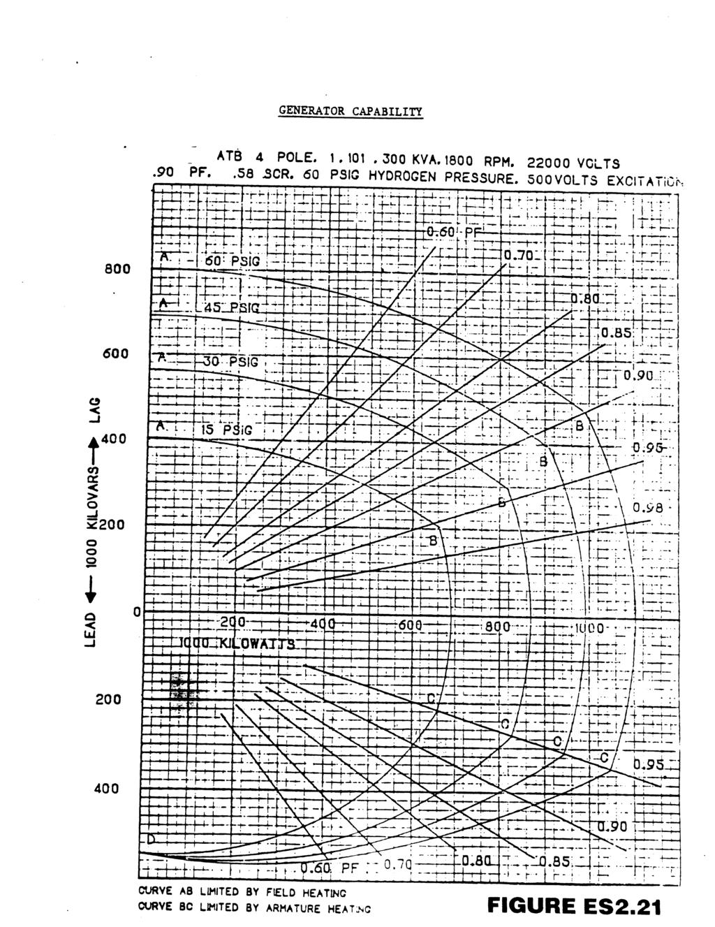
96
97
98
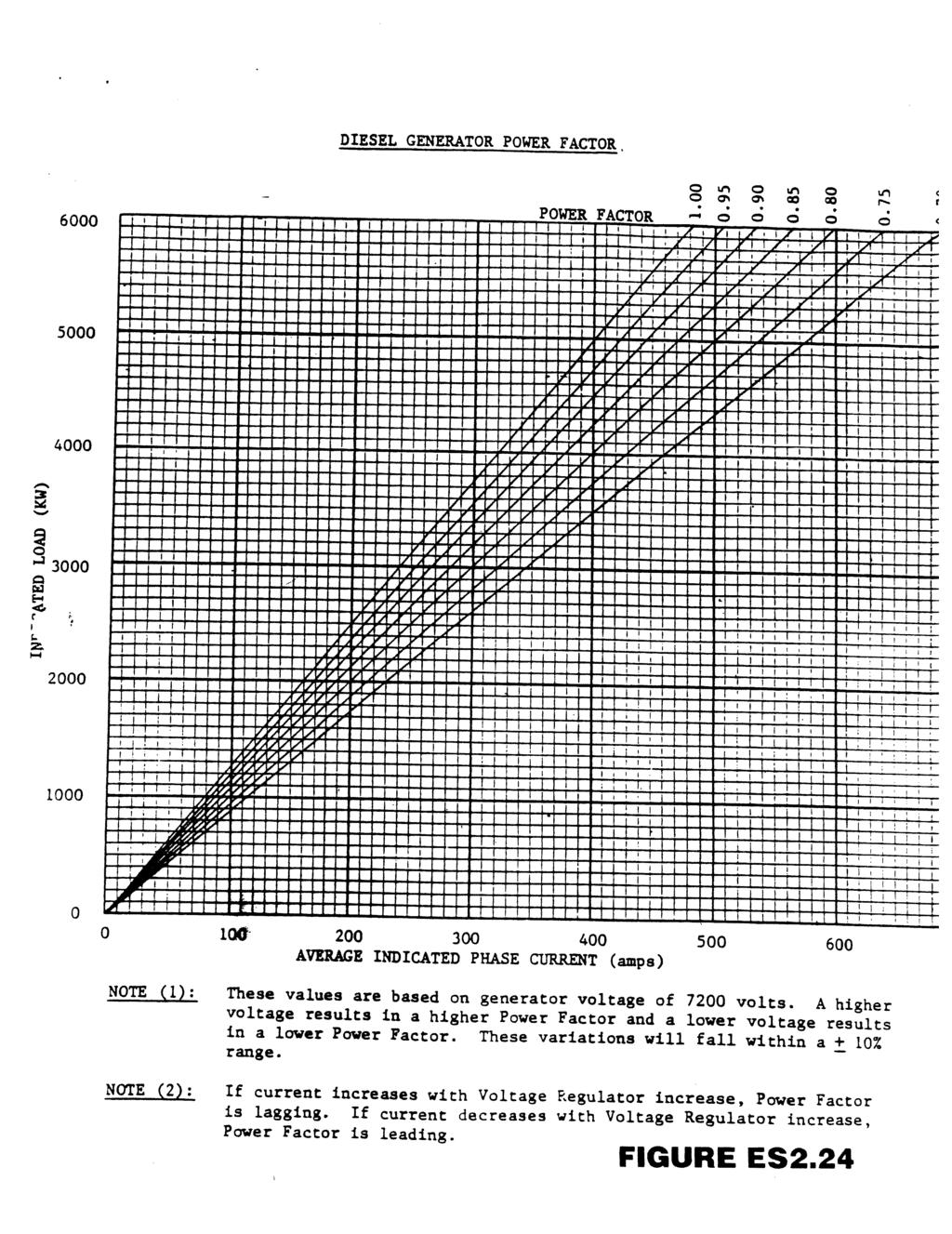
99
100
101
102
103
104
105
106
107
108
109
110
111
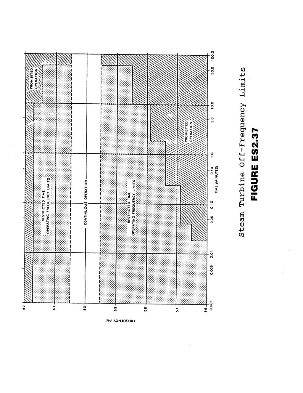
112
Pretest Module 21 Units 1-4 AC Generators & Three-Phase Motors
 Pretest Module 21 Units 1-4 AC Generators & Three-Phase Motors 1. What are the two main parts of a three-phase motor? Stator and Rotor 2. Which part of a three-phase squirrel-cage induction motor is a
EEE3441 Electrical Machines Department of Electrical Engineering. Lecture. Introduction to Electrical Machines
 Department of Electrical Engineering Lecture Introduction to Electrical Machines 1 In this Lecture Induction motors and synchronous machines are introduced Production of rotating magnetic field Three-phase
Electrical Theory. Generator Theory. PJM State & Member Training Dept. PJM /22/2018
 Electrical Theory Generator Theory PJM State & Member Training Dept. PJM 2018 Objectives The student will be able to: Describe the process of electromagnetic induction Identify the major components of
Basics of Paralleling
 Basics of Paralleling Revised: February 1, 2017 2017 Cummins All Rights Reserved Course Objectives Participants will be able to: Discuss basic paralleling control functions to gain a better understanding
AIR COOLED RECTIFIER SPECIFICATION S-50-A
 SPECIFICATIONS AIR COOLED RECTIFIER Spec50a1 5JAN1999 SPECIFICATION S-50-A HIGH VOLTAGE SINGLE TRANSFORMER AIR COOLED RECTIFIER Standard output power range: 250 to 600 volts at 100 to 1,200 amperes TECHNICAL
Synchronous Generators I. Spring 2013
 Synchronous Generators I Spring 2013 Construction of synchronous machines In a synchronous generator, a DC current is applied to the rotor winding producing a rotor magnetic field. The rotor is then turned
UNIT 2. INTRODUCTION TO DC GENERATOR (Part 1) OBJECTIVES. General Objective
 OBJECTIVES. General Objective") DC GENERATOR (Part 1) E2063/ Unit 2/ 1 UNIT 2 INTRODUCTION TO DC GENERATOR (Part 1) OBJECTIVES General Objective : To apply the basic principle of DC generator, construction principle and types of DC generator.
DC GENERATOR (Part 1) E2063/ Unit 2/ 1 UNIT 2 INTRODUCTION TO DC GENERATOR (Part 1) OBJECTIVES General Objective : To apply the basic principle of DC generator, construction principle and types of DC generator.
Synchronous Generators I. EE 340 Spring 2011
 Synchronous Generators I EE 340 Spring 2011 Construction of synchronous machines In a synchronous generator, a DC current is applied to the rotor winding producing a rotor magnetic field. The rotor is
Electrical Machines -II
 Objective Type Questions: 1. Basically induction machine was invented by (a) Thomas Alva Edison (b) Fleming (c) Nikola Tesla (d) Michel Faraday Electrical Machines -II 2. What will be the amplitude and
Pretest Module 21 Units 1-3 AC Generators & Three-Phase Motors
 Pretest Module 21 Units 1-3 AC Generators & Three-Phase Motors 1. What are the two main parts of a three-phase 2. Which part of a three-phase squirrel-cage induction motor is a hollow core? 3. What are
EE6351 ELECTRIC DRIVES AND CONTROL UNIT-1 INTRODUTION
 EE6351 ELECTRIC DRIVES AND CONTROL UNIT-1 INTRODUTION 1. What is meant by drive and electric drive? Machines employed for motion control are called drives and may employ any one of the prime movers for
BELT-DRIVEN ALTERNATORS
 CHAPTER 13 BELT-DRIVEN ALTERNATORS INTRODUCTION A generator is a machine that converts mechanical energy into electrical energy using the principle of magnetic induction. This principle is based on the
34 th Hands-On Relay School
 34 th Hands-On Relay School Generation Track Overview Lecture Generator Design, Connections, and Grounding 1 Generator Main Components Stator Core lamination Winding Rotor Shaft Poles Slip rings Stator
2014 ELECTRICAL TECHNOLOGY
 SET - 1 II B. Tech I Semester Regular Examinations, March 2014 ELECTRICAL TECHNOLOGY (Com. to ECE, EIE, BME) Time: 3 hours Max. Marks: 75 Answer any FIVE Questions All Questions carry Equal Marks ~~~~~~~~~~~~~~~~~~~~~~~~~~
ISO Rules Part 500 Facilities Division 502 Technical Requirements Section Interconnected Electric System Protection Requirements
 Applicability 1 Section 502.3 applies to: the legal owner of a generating unit directly connected to the transmission system with a maximum authorized real power rating greater than 18 MW; the legal owner
INSTITUTE OF AERONAUTICAL ENGINEERING Dundigal, Hyderabad
 INSTITUTE OF AERONAUTICAL ENGINEERING Dundigal, Hyderabad - 500 043 MECHANICAL ENGINEERING ASSIGNMENT Name : Electrical and Electronics Engineering Code : A40203 Class : II B. Tech I Semester Branch :
INTRODUCTION Principle
 DC Generators INTRODUCTION A generator is a machine that converts mechanical energy into electrical energy by using the principle of magnetic induction. Principle Whenever a conductor is moved within a
DEPARTMENT OF ELECTRICAL AND ELECTRONICS ENGINEERING
 DEPARTMENT OF ELECTRICAL AND ELECTRONICS ENGINEERING QUESTION BANK 16EET41 SYNCHRONOUS AND INDUCTION MACHINES UNIT I SYNCHRONOUS GENERATOR 1. Why the stator core is laminated? 2. Define voltage regulation
DC CIRCUITS ELECTROMAGNETISM
 DC CIRCUITS 1. State and Explain Ohm s Law. Write in brief about the limitations of Ohm s Law. 2. State and explain Kirchhoff s laws. 3. Write in brief about disadvantages of series circuit and advantages
Handout Activity: HA773
 Charging system HA773-2 Handout Activity: HA773 Charging system The charging system allows for a means to recharge the battery and allow for electrical usage of components in the vehicle. The charging
CHAPTER 6 DESIGN AND DEVELOPMENT OF DOUBLE WINDING INDUCTION GENERATOR
 100 CHAPTER 6 DESIGN AND DEVELOPMENT OF DOUBLE WINDING INDUCTION GENERATOR 6.1 INTRODUCTION Conventional energy resources are not sufficient to meet the increasing electrical power demand. The usages of
SECTION MOTOR CONTROL
 SECTION 26 24 19 MOTOR CONTROL PART 1 - GENERAL 1.1 SECTION INCLUDES A. Manual motor starters B. Magnetic motor starters C. Combination magnetic motor starters D. Solid-state reduced voltage motor starters
Legal Name of the Customer (or, if an individual, individual's name): Name: Contact Person: Mailing Address: Physical Address: City: State: Zip Code:
: Name: Contact Person: Mailing Address: Physical Address: City: State: Zip Code:") Generating Facility Level 2 or 3 Interconnection Review (For Generating Facilities with Electric Nameplate Capacities no Larger than 20 MW) Instructions An Interconnection Customer who requests a Utah
Generating Facility Level 2 or 3 Interconnection Review (For Generating Facilities with Electric Nameplate Capacities no Larger than 20 MW) Instructions An Interconnection Customer who requests a Utah
Ch 4 Motor Control Devices
 Ch 4 Motor Control Devices Part 1 Manually Operated Switches 1. List three examples of primary motor control devices. (P 66) Answer: Motor contactor, starter, and controller or anything that control the
SECTION 4 ELECTRIC MOTORS UNIT 17: TYPES OF ELECTRIC MOTORS UNIT OBJECTIVES UNIT OBJECTIVES 3/21/2012
 SECTION 4 ELECTRIC MOTORS UNIT 17: TYPES OF ELECTRIC MOTORS UNIT OBJECTIVES After studying this unit, the reader should be able to Describe the different types of open single-phase motors used to drive
Principles of Electrical Engineering
 D.C GENERATORS Principle of operation of D.C machines, types of D.C Generators, e.m.f equation of D.C Generator, O.C.C of a D.C Shunt Generator, Load characteristics of D.C.Generators GENERATOR PRINCIPLE:
CSDA Best Practice. Hi-Cycle Concrete Cutting Equipment. Effective Date: Oct 1, 2010 Revised Date:
 CSDA Best Practice Title: Hi-Cycle Concrete Cutting Equipment Issue No: CSDA-BP-010 : Oct 1, 2010 Revised : Introduction Hi-cycle/high frequency concrete cutting equipment has become more prevalent in
Electric Motor Controls BOMA Pre-Quiz
 Electric Motor Controls BOMA Pre-Quiz Name: 1. How does a U.P.S. (uninterruptable power supply) work? A. AC rectified to DC batteries then inverted to AC B. Batteries generate DC power C. Generator, batteries,
Electrical Machines II. Week 5-6: Induction Motor Construction, theory of operation, rotating magnetic field and equivalent circuit
 Electrical Machines II Week 5-6: Induction Motor Construction, theory of operation, rotating magnetic field and equivalent circuit Asynchronous (Induction) Motor: industrial construction Two types of induction
Chapter 8. Understanding the rules detailed in the National Electrical Code is critical to the proper installation of motor control circuits.
 Chapter 8 Understanding the rules detailed in the National Electrical Code is critical to the proper installation of motor control circuits. Article 430 of the NEC covers application and installation of
L. Photo. Figure 2: Types CA-16 Relay (rear view) Photo. Figure 1: Types CA-16 Relay (front view)
 Photo. Figure 1: Types CA-16 Relay (front view)") Figure 1: Types CA-16 Relay (front view) Photo Figure 2: Types CA-16 Relay (rear view) Photo 2 Sub 5 185A419 Sub 6 185A443 Figure 3: Internal Schematic of the Type CA-16 bus Relay or CA-26 Transformer
Figure 1: Types CA-16 Relay (front view) Photo Figure 2: Types CA-16 Relay (rear view) Photo 2 Sub 5 185A419 Sub 6 185A443 Figure 3: Internal Schematic of the Type CA-16 bus Relay or CA-26 Transformer
RT2DB Excitation and voltage regulation system for synchronous generators
 s RT2DB Excitation and voltage regulation system for synchronous generators Fully digital. Parameter settings done by software. Self monitoring routines. Maintenance free. High reliability. Excellent dynamic
MX431 Generator Automatic Voltage Regulator Operation Manual
 Generator Automatic Voltage Regulator Operation Manual Self Excited Automatic Voltage Regulator 1 1. SPECIFICATION Sensing Input Voltage Frequency 190 ~ 264 VAC Max, 1 phase, 2 wire 50 / 60 Hz, selectable
Note 8. Electric Actuators
 Note 8 Electric Actuators Department of Mechanical Engineering, University Of Saskatchewan, 57 Campus Drive, Saskatoon, SK S7N 5A9, Canada 1 1. Introduction In a typical closed-loop, or feedback, control
AE105 PRINCIPLES OF ELECTRICAL ENGINEERING JUNE 2014
 Q.2 a. Explain in detail eddy current losses in a magnetic material. Explain the factors on which it depends. How it can be reduced? IETE 1 b. A magnetic circuit with a single air gap is shown in given
Power Systems Trainer
 Electrical Power Systems PSS A self-contained unit that simulates all parts of electrical power systems and their protection, from generation to utilisation Key Features Simulates generation, transmission,
Synchronous motor control. 8/15/2007 Powerflow Technologies Inc 1
 Synchronous motor control 8/15/2007 Powerflow Technologies Inc 1 PLC Lubrication units Cooling Water DCS PLC Dampers SUB BD Breaker Protection relay Field Application Kiln System Fan Hydraulic Unit Instrumentation
10. Starting Method for Induction Motors
 10. Starting Method for Induction Motors A 3-phase induction motor is theoretically self starting. The stator of an induction motor consists of 3-phase windings, which when connected to a 3-phase supply
Short Term Course On Hydropower Development Engineering (Electrical) for Teachers of Polytechnics in Uttarakhand L33-2
 for Teachers of Polytechnics in Uttarakhand L33-2") Short Term Course On Hydropower Development Engineering (Electrical) for Teachers of Polytechnics in Uttarakhand ( July 14-18, 2007) Lecture on L33-2 By S.N.Singh Senior Scientific officer ALTERNATE HYDRO
Short Term Course On Hydropower Development Engineering (Electrical) for Teachers of Polytechnics in Uttarakhand ( July 14-18, 2007) Lecture on L33-2 By S.N.Singh Senior Scientific officer ALTERNATE HYDRO
 8803214-8803999 DIODE BOARD The diode board is located inside the lower control box. D15 D8 D7 D14 D5 D13 ART_2181 J1 14 8 D9 D10 7 1 R2 R1 R3 R4 TB1 8601 D11 D3 D12 D4 D1 D2 J1 Plug Pin Identification
 DIODE BOARD The diode board is located inside the lower control box. D15 D8 D7 D14 D5 D13 ART_2181 J1 14 8 D9 D10 7 1 R2 R1 R3 R4 TB1 8601 D11 D3 D12 D4 D1 D2 J1 Plug Pin Identification PIN # WIRE # SIGNAL
Single-Phase AC Induction Squirrel Cage Motors. Permanent Magnet Series Wound Shunt Wound Compound Wound Squirrel Cage. Induction.
 FAN ENGINEERING Information and Recommendations for the Engineer Twin City Fan FE-1100 Single-Phase AC Induction Squirrel Cage Motors Introduction It is with the electric motor where a method of converting
MaxPak Plus Analog DC V S Drive
 Three-Phase 3-600 HP non-regenerative and 5-150 HP regenerative drives Designed to accommodate a wide range of industrial requirements, the DC V S Drive has been widely applied worldwide. Selected ratings
CHAPTER THREE DC MOTOR OVERVIEW AND MATHEMATICAL MODEL
 CHAPTER THREE DC MOTOR OVERVIEW AND MATHEMATICAL MODEL 3.1 Introduction Almost every mechanical movement that we see around us is accomplished by an electric motor. Electric machines are a means of converting
Comprehensive Technical Training
 Comprehensive Technical Training For Sugar Mills Staff on Operation & Maintenance of Baggase Based HP Cogeneration System Schedule: 10 th July to 13 th July, 2017 A.C. GENERATOR Topics Covered. Introduction.
Renewable Energy Systems 13
 Renewable Energy Systems 13 Buchla, Kissell, Floyd Chapter Outline Generators 13 Buchla, Kissell, Floyd 13-1 MAGNETISM AND ELECTROMAGNETISM 13-2 DC GENERATORS 13-3 AC SYNCHRONOUS GENERATORS 13-4 AC INDUCTION
CHAPTER 6 INTRODUCTION TO MOTORS AND GENERATORS
 CHAPTER 6 INTRODUCTION TO MOTORS AND GENERATORS Objective Describe the necessary conditions for motor and generator operation. Calculate the force on a conductor carrying current in the presence of the
Power Solutions Manager Generac Power Systems, Inc.
 Engine Generator Paralleling Concepts Gen. #1 Gen. #2 Gen. #3 Gen. #4 Gen. #5 Presenter: Daniel Barbersek Power Solutions Manager Generac Power Systems, Inc. RUNNING HEADLINE What Topics Will Be Covered
ECET 211 Electric Machines & Controls Lecture 8 Motor Control Circuits (1 of 2) Lecture 8 Motor Control Circuits
 Lecture 8 Motor Control Circuits") ECET 211 Electric Machines & Controls Lecture 8 Motor Control Circuits (1 of 2) Text Book: Electric Motors and Control Systems, by Frank D. Petruzella, published by McGraw Hill, 2015. Paul I-Hai Lin, Professor
ECET 211 Electric Machines & Controls Lecture 8 Motor Control Circuits (1 of 2) Text Book: Electric Motors and Control Systems, by Frank D. Petruzella, published by McGraw Hill, 2015. Paul I-Hai Lin, Professor
Design considerations for generator set mounted paralleling breakers
 Our energy working for you. Design considerations for generator set mounted paralleling breakers White Paper Hassan Obeid, Application Group Cummins Power Generation Cummins Power Systems has been delivering
To discover the factors affecting the direction of rotation and speed of three-phase motors.
 EXPERIMENT 12 Direction of Rotation of Three-Phase Motor PURPOSE: To discover the factors affecting the direction of rotation and speed of three-phase motors. BRIEFING: The stators of three-phase motors
ECE 325 Electric Energy System Components 6 Three Phase Induction Motors. Instructor: Kai Sun Fall 2016
 ECE 325 Electric Energy System Components 6 Three Phase Induction Motors Instructor: Kai Sun Fall 2016 1 Content (Materials are from Chapters 13-15) Components and basic principles Selection and application
825-P Modular Protection System for motors Specification Guide
 Specification Guide 1.0 General 1.01 The motor protection relay shall have a current operating range of 0.5 and 5000 amperes. 1.02 The motor protection relay shall provide current measurement-based protection
DEPARTMENT OF EI ELECTRICAL MACHINE ASSIGNMENT 1
 It is the mark of an educated mind to be able to entertain a thought without accepting it. DEPARTMENT OF EI ELECTRICAL MACHINE ASSIGNMENT 1 1. Explain the Basic concepts of rotating machine. 2. With help
C. Figure 1. CA-16 Front View Figure 2. CA-16 Rear View
 Figure 1. CA-16 Front View Figure 2. CA-16 Rear View 2 2.1. Restraint Elements Each restraint element consists of an E laminated electromagnet with two primary coils and a secondary coil on its center
SHORT-STOP. Electronic Motor Brake Type G. Instructions and Setup Manual
 Electronic Motor Brake Type G Instructions and Setup Manual Table of Contents Table of Contents Electronic Motor Brake Type G... 1 1. INTRODUCTION... 2 2. DESCRIPTION AND APPLICATIONS... 2 3. SAFETY NOTES...
EXPERIMENT CALIBRATION OF 1PHASE ENERGY METER
 EXPERIMENT CALIBRATION OF PHASE ENERGY METER THEORY:- Energy Meters are integrating instruments used to measure the quantity of electrical energy supplied to a circuit in a given time. Single phase energy
MANTECH ELECTRONICS. Stepper Motors. Basics on Stepper Motors I. STEPPER MOTOR SYSTEMS OVERVIEW 2. STEPPING MOTORS
 MANTECH ELECTRONICS Stepper Motors Basics on Stepper Motors I. STEPPER MOTOR SYSTEMS OVERVIEW 2. STEPPING MOTORS TYPES OF STEPPING MOTORS 1. VARIABLE RELUCTANCE 2. PERMANENT MAGNET 3. HYBRID MOTOR WINDINGS
 APGENCO/APTRANSCO Assistant Engineer Electrical Previous Question Papers Q.1 The two windings of a transformer is conductively linked. inductively linked. not linked at all. electrically linked. Q.2 A
SPH3U UNIVERSITY PHYSICS
 SPH3U UNIVERSITY PHYSICS ELECTRICITY & MAGNETISM L (P.599-604) The large-scale production of electrical energy that we have today is possible because of electromagnetic induction. The electric generator,
MOTOR TERMINAL CONNECTIONS
 MOTOR TERMINAL CONNECTIONS Motor Classification Most of the industrial machines in use today are driven by electric motors Motors are classified according to the type of power used (AC or DC) and the motors
SE-3SCR-LM MANUAL MOTOR LOAD MANAGER
 3714 Kinnear Place Saskatoon, SK Canada S7P 0A6 Ph: (306) 373-5505 Fx: (306) 374-2245 www.littelfuse.com/relayscontrols SE-3SCR-LM MANUAL MOTOR LOAD MANAGER MARCH 5, 2013 REVISION 4 MOTOR LOAD MANAGER
MANUAL ELECTRIC FIRE PUMP CONTROLLERS METRON SERIES M450
 MANUAL ELECTRIC FIRE PUMP CONTROLLERS METRON SERIES M450 TABLE OF CONTENTS PART I GENERAL DESCRIPTION... PAGE 2 PART II FUNCTIONS... PAGE 2 PART III INSTALLATION... PAGE 3 PART IV INITIAL INSTALLATION
Full Voltage Starting (Number of Starts):
:") Starting Method Full Voltage Starting (Number of Starts): Squirrel cage induction motors are designed to accelerate a NEMA inertia along a NEMA load curve with rated voltage applied to the motor terminals.
Starting Method Full Voltage Starting (Number of Starts): Squirrel cage induction motors are designed to accelerate a NEMA inertia along a NEMA load curve with rated voltage applied to the motor terminals.
Historical Development
 TOPIC 3 DC MACHINES DC Machines 2 Historical Development Direct current (DC) motor is one of the first machines devised to convert electrical power into mechanical power. Its origin can be traced to the
Unit Protection System for Pumped-Storage Power Stations
 Unit Protection System for Pumped-Storage Power Stations 1. Introduction In many power systems, pumped-storage power stations are used in addition to run-of-river power stations. These power stations serve
Regulation: R16 Course & Branch: B.Tech EEE
 SIDDHARTH GROUP OF INSTITUTIONS :: PUTTUR Siddharth Nagar, Narayanavanam Road 517583 QUESTION BANK (Descriptive) Subject with Code : Electrical Machines-II (16EE215) Regulation: R16 Course & Branch: B.Tech
The Wound-Rotor Induction Motor Part I
 Experiment 1 The Wound-Rotor Induction Motor Part I OBJECTIVE To examine the construction of the three-phase wound-rotor induction motor. To understand exciting current, synchronous speed and slip in a
ENSC387: Introduction to Electromechanical Sensors and Actuators LAB 5: DC MOTORS WARNING:
 ENSC387: Introduction to Electromechanical Sensors and Actuators LAB 5: DC MOTORS WARNING: Please be extremely cautious to precisely follow the procedures described in this manual. It is very easy to break
Part- A Objective Questions (10X1=10 Marks)
") Dr. Mahalingam College of Engineering and Technology, Pollachi-3 (An Autonomous Institution) CCET 3(2016Regulation) Name of Programme: B.E. (EEE) Course Code&Course Title: 16EET41 & Synchronous & Induction
Dr. Mahalingam College of Engineering and Technology, Pollachi-3 (An Autonomous Institution) CCET 3(2016Regulation) Name of Programme: B.E. (EEE) Course Code&Course Title: 16EET41 & Synchronous & Induction
SALDET SALES & SERVICE, INC. CLINTON TOWNSHIP, MICHIGAN
 Form 1254 BRAKETRON Electronic Motor Brake Instructions SALDET SALES & SERVICE, INC. CLINTON TOWNSHIP, MICHIGAN TABLE OF CONTENTS SECTION TITLE PAGE I. Introduction 1 II. Specifications 1 III. Principles
Motor Protection Fundamentals. Motor Protection - Agenda
 Motor Protection Fundamentals IEEE SF Power and Energy Society May 29, 2015 Ali Kazemi, PE Regional Technical Manager Schweitzer Engineering Laboratories Irvine, CA Copyright SEL 2015 Motor Protection
ROTATING MAGNETIC FIELD
 Chapter 5 ROTATING MAGNETIC FIELD 1 A rotating magnetic field is the key to the operation of AC motors. The magnetic field of the stator is made to rotate electrically around and around in a circle. Stator
Almost 200 years ago, Faraday looked for evidence that a magnetic field would induce an electric current with this apparatus:
 Chapter 21 Electromagnetic Induction and Faraday s Law Chapter 21 Induced EMF Faraday s Law of Induction; Lenz s Law EMF Induced in a Moving Conductor Changing Magnetic Flux Produces an E Field Inductance
Synchronous motor with fluid coupling drive arrangement for a preheater ID Fan. presenter Nathan Schachter CIMENTEC Engineering Ltd
 Synchronous motor with fluid coupling drive arrangement for a preheater ID Fan presenter Nathan Schachter SLC PLC Lubrication units Cooling Water DCS SUB BD Breaker SR469 GE STAT-XTOR PLC Field Application
Starting of Induction Motors
 1- Star Delta Starter The method achieved low starting current by first connecting the stator winding in star configuration, and then after the motor reaches a certain speed, throw switch changes the winding
Electrical Machines-I (EE-241) For S.E (EE)
 For S.E (EE)") PRACTICAL WORK BOOK For Academic Session 2013 Electrical Machines-I (EE-241) For S.E (EE) Name: Roll Number: Class: Batch: Department : Semester/Term: NED University of Engineer ing & Technology Electrical
PRACTICAL WORK BOOK For Academic Session 2013 Electrical Machines-I (EE-241) For S.E (EE) Name: Roll Number: Class: Batch: Department : Semester/Term: NED University of Engineer ing & Technology Electrical
INSTRUCTION MANUAL FOR VOLTAGE REGULATOR APR P/N
 INSTRUCTION MANUAL FOR VOLTAGE REGULATOR APR 125-5 P/N 9168800100 Publication: 9168800990 Revision: J 03/09 INTRODUCTION This instruction manual provides information about the operation and installation
MAGNAMAX DVR DIGITAL VOLTAGE REGULATOR
 MAGNAMAX DVR DIGITAL VOLTAGE REGULATOR TECHNICAL MANUAL MODEL DVR 2000 AND DVR 2000C FIGURE 1 - FRONT AND REAR VIEW OF VOLTAGE REGULATOR...4 SECTION 1- INTRODUCTION...5 GENERAL DESCRIPTION...5 SPECIFICATIONS...5
INSTALLATION AND SET-UP MANUAL FOR THE NEW: AVR-07. A CONTROLPAK AVR Automatic Voltage Regulator for three-phase and single-phase alternators
 INSTALLATION AND SET-UP MANUAL FOR THE NEW: AVR-07 A CONTROLPAK AVR Automatic Voltage Regulator for three-phase and single-phase alternators This is a premium quality product at a reasonable price, and
Unit 32 Three-Phase Alternators
 Unit 32 Three-Phase Alternators Objectives: Discuss the operation of a three-phase alternator. Explain the effect of rotation speed on frequency. Explain the effect of field excitation on output voltage.
PRIMELINE. Induction Generator. Now Introducing Single Bearing Designs. Simple, Reliable Power For Wind or Engine Driven Applications
 PRIMELINE Induction Generator Now Introducing Single Bearing Designs Simple, Reliable Power For Wind or Engine Driven Applications ISO 9001: 2000 Certified PRIMELINE Induction Generator General Description
DHANALAKSHMI COLLEGE OF ENGINEERING DEPARTMENT OF MECHANICAL ENGINEERING ME 6351 ELECTRICAL DRIVES AND CONTROL UNIVERSITY QUESTIONS AND ANSWERS
 DHANALAKSHMI COLLEGE OF ENGINEERING DEPARTMENT OF MECHANICAL ENGINEERING ME 6351 ELECTRICAL DRIVES AND CONTROL UNIVERSITY QUESTIONS AND ANSWERS 1) What is the Necessity of starter? UNIT 3 Two Marks Both
Data Bulletin. Ground-Censor Ground-Fault Protection System Type GC Class 931
 Data Bulletin 0931DB0101 July 2001 Cedar Rapids, IA, USA Ground-Censor Ground-Fault Protection System Type GC Class 931 09313063 GT Sensor Shunt Trip of Circuit Interrupter Window Area for Conductors GC
INDEX Section Page Number Remarks
 INDEX Section Page Number Remarks Synchronous Alternators 2 4 General Fault Finding Capacitors 5 6 Fault Finding & Testing Diodes,Varistors, EMC capacitors & Recifiers 7 10 Fault Finding & Testing Rotors
2-marks question bank UNIT I - TRANSFORMERS UNIT II: AC MACHINES
 2-marks question bank UNIT I - TRANSFORMERS 1. What is all day efficiency? 2. What are the applications of auto transformers? 3. Why transformer rating is expressed in KVA? 4. Does transformer draw any
Direct On Line (DOL) Motor Starter. Direct Online Motor Starter
 Motor Starter. Direct Online Motor Starter") Direct On Line (DOL) Motor Starter Direct Online Motor Starter Different starting methods are employed for starting induction motors because Induction Motor draws more starting current during starting.
Direct On Line (DOL) Motor Starter Direct Online Motor Starter Different starting methods are employed for starting induction motors because Induction Motor draws more starting current during starting.
R07 SET - 1
 R07 SET - 1 II B. Tech II Semester Supplementary Examinations April/May 2013 ELECTRICAL MACHINES - II (Electrical and Electronics Engineering) Time: 3 hours Max. Marks: 80 Answer any FIVE Questions All
VIII. Three-phase Induction Machines (Asynchronous Machines) Induction Machines
 Induction Machines") VIII. Three-phase Induction Machines (Asynchronous Machines) Induction Machines 1 Introduction Three-phase induction motors are the most common and frequently encountered machines in industry simple design,
VIII. Three-phase Induction Machines (Asynchronous Machines) Induction Machines 1 Introduction Three-phase induction motors are the most common and frequently encountered machines in industry simple design,
Chapter 29 Electromagnetic Induction and Faraday s Law
 Chapter 29 Electromagnetic Induction and Faraday s Law 29.1 Induced EMF Units of Chapter 29 : 1-8 29.3 EMF Induced in a Moving Conductor: 9, 10 29.4 Electric Generators: 11 29.5 Counter EMF and Torque;
(d) None of the above.
 None of the above.") Dr. Mahalingam College of Engineering and Technology, Pollachi-3 (An Autonomous Institution affiliated to Anna niversity) CCET II (2016 Regulation) Name of Programme: B.E. (EEE) Course Code & Course Title:
Dr. Mahalingam College of Engineering and Technology, Pollachi-3 (An Autonomous Institution affiliated to Anna niversity) CCET II (2016 Regulation) Name of Programme: B.E. (EEE) Course Code & Course Title:
Most home and business appliances operate on single-phase AC power. For this reason, singlephase AC motors are in widespread use.
 Chapter 5 Most home and business appliances operate on single-phase AC power. For this reason, singlephase AC motors are in widespread use. A single-phase induction motor is larger in size, for the same
Electrical Systems - Course 135 COMPOSITE ELECTRICAL PROTECTIVE SCHEMES: PART II
 135 05-1 Electrical Systems - Course 135 COMPOSITE ELECTRICAL PROTECTIVE SCHEMES: PART II TURBINE-GENERATOR: rhipping AND ALARM CIRCUITS i.o' I titrodljction Following on from Lessons 135.03-1 and 135.04-1,
Institute of Technology, Nirma University B. Tech. Sem. V: Electrical Engineering 2EE305: ELECTRICAL MACHINES II. Handout: AC Commutator Motors
 Institute of Technology, Nirma University B. Tech. Sem. V: Electrical Engineering 2EE305: ELECTRICAL MACHINES II Handout: AC Commutator Motors Prepared by: Prof. T. H. Panchal Learning Objective: Introduction
Introduction. Upon completion of AC Motors you should be able to: Explain the concepts of force, inertia, speed, and torque
 Table of Contents Introduction...2 AC Motors...4 Force and Motion...6 Energy... 11 Electrical Energy... 13 AC Motor Construction... 17 Magnetism... 23 Electromagnetism... 25 Developing a Rotating Magnetic
GENERATION, CONVERSION, OR DISTRIBUTION OF ELECTRIC POWER
 XXXX H02 GENERATION, CONVERSION, OR DISTRIBUTION OF ELECTRIC POWER XXXX CONTROL OR REGULATION OF ELECTRIC MOTORS, GENERATORS, OR DYNAMO-ELECTRIC CONVERTERS; CONTROLLING TRANSFORMERS, REACTORS OR CHOKE
Research and Reviews: Journal of Engineering and Technology
 Research and Reviews: Journal of Engineering and Technology Brushless Excitation System of Turbo Generator Komala Koila* Department of Electrical and Electronics, Khammam Institute of Technology and Sciences,
INSTRUCTION MANUAL FOR
 INSTRUCTION MANUAL FOR VOLTAGE REGULATOR Model: SR32A Part Number: 9 0750 00 104 Publication Number: 9 0750 00 990 Date: January, 1979 Revision G: March, 1997 SECTION 1 GENERAL INFORMATION 1-1. INTRODUCTION
Fachpraktikum Elektrische Maschinen. Theory of Induction Machines
 Fachpraktikum Elektrische Maschinen Theory of Induction Machines Prepared by Arda Tüysüz January 2013 Fundamentals Induction machines (also known as asynchronous machines) are by far the most common type
SPH3U1 Lesson 10 Magnetism. If the wire through a magnetic field is bent into a loop, the loop can be made to turn up to 90 0.
 SPH3U1 Lesson 10 Magnetism GALVAOMETERS If the wire through a magnetic field is bent into a loop, the loop can be made to turn up to 90 0. otice how the current runs in the opposite directions on opposite