CALIFORNIA SIDECAR TRIKE CONVERSION KIT INSTALLATION INSTRUCTIONS MODEL YEARS. For installation assistance, call Parts & Technical iii PAGE
|
|
|
- Christine Lawson
- 5 years ago
- Views:
Transcription


1 CALIFORNIA SIDECAR TRIKE CONVERSION KIT INSTALLATION INSTRUCTIONS GOLD WING MODEL YEARS For installation assistance, call Parts & Technical (434) SECTION TABLE OF CONTENTS Introduction..... PAGE iii i
2 Step 1. Dismantling & Preparing the Motorcycle 1 Step 2. Removing the Rear Wheel and Drive Unit... 2 Step 3. Removing the Swing Arm. 3 Step 4. Prepare the Frame Step 5. Auxiliary Fuel Tank Step 6. Install Brake Line Step 7. Install Swing Arm Step 8. Step 9. Step 10. Step 11. Step 12. Step 13. Step 14. Install Rear End Install Spring and Air Shock Install Body Frame Install Muffler.. 13 Installing ng Trailer Hitch & Wiring Installing Front Wheel Crossover Brake Line Installing New Front Brake Master Cylinder Wiring Schematic INTRODUCTION DISCLAIMER - These instructions assume a level of understanding of motorcycle repair and maintenance beyond that of a beginner or novice, and California Sidecar cannot be liable for an installer s failure to understand or follow these instructions as written. Likewise, California Sidecar cannot be responsible if any of the steps are omitted or shortcuts are taken, or parts other than those supplied by CSC, are used in installing this trike conversion kit. ii
3 WARNINGS are printed in bold type. PLEASE USE EXTREME CARE so as not to damage the part, the motorcycle, or yourself!! ALWAYS wear safety glasses when working with hand and power tools, and when working with or around any harmful or hazardous materials! Additionally, when working in and around the fuel system, ALWAYS work in a well ventilated area free from sparks and open flames! DIRECTIONAL REFERENCES All references to right and left side are as if one is seated on the motorcycle. All references to forward mean toward the front of the motorcycle while back means toward the rear of the motorcycle unless otherwise stated. SAVING AND DISCARDING PARTS - During installation, if parts are intended to be saved for later use, they are marked SAVE in italics. If removed parts are not marked SAVE, they may be discarded. LIST OF TOOLS AND EQUIPMENT - This list contains only those items that might be construed as out of the ordinary for someone repairing a motorcycle. A COPY OF THE GL1500 SERVICE MANUAL IS ESSENTIAL TO THIS INSTALLATION. Trike Installation Auxiliary Fuel Tank Installation 5/16 drill bit 7/8 or 22.5mm Knockout Punch Flat Black Spray Paint 3/8 X 18 drill bit Floor Jack 12 socket extension Hack Saw or Sawsall Ring Pliers Power Trak Installation Silicone Sealer Honda Fork Bolt Assembly Tool Super Glue (#07KMF-MT20300) Teflon Sealing Tape Trailer Hitch Installation 1/8 X 8 or 3/16 X 8 drill bit iii
4 OTICE THIS MUST BE DO E FIRST!!!!!!! Step 14 of these instructions is related to the installation of the front brake master cylinder, which has been modified to accept a larger piston for more efficient braking. The modification cost is included in the purchase price, however, because there are several different types of GL1500 master cylinders, it is necessary for you to send us your master cylinder so we are able to match your specific type and return a modified part. It will be returned to you via UPS 2-day service within 24 hours after we receive it. Please drain all brake fluid and remove all parts except the stainless steel protector covering the bleed hole inside the fluid reservoir. Also, include a copy of your order invoice which indicates the ORDER ID so that we are able to identify the master cylinder and your return address. We appreciate your cooperation. Questions? Please call the Parts & Service Dept Return to: California Sidecar 100 Motorcycle Run Arrington, VA Attention: MASTER CYLINDER CALIFORNIA SIDECAR TRIKE KIT INSTALLATION INSTRUCTIONS FOR OR GL DISMANTLING & PREPARING THE MOTORCYCLE 1. ALL ITEMS BEING REMOVED SHOULD BE IN ACCORDANCE WITH THE GL1500 SERVICE MANUAL. 1.1 Remove the following: seat, tour box (and all attachments), two (2) red plugs, all accessory wires, cables, and license plate. Loosen the release cables and remove them from trigger mechanisms on the levers. Remove four (4) bolts that attach tour box to motorcycle frame. 1.2 Remove rear crash guards by the two (2) bolts on each side. These may be discarded. When removing both saddlebags, make sure you disconnect the cables from the release rod in each bag, then remove the four (4) support bolts. Remove core parts from the lid and inside the saddlebags to be returned to California Sidecar as part of the core parts kit. 1.3 Remove passenger footrests. Remove two (2) bolts that mount them to the frame. Note: On SE models, you will also have an adjusting cable. Pull lower chrome cover off the footrest. Take the two (2) lower screws out (brass in color) and remove two (2) support bolts. Detach from behind the release cable. 1.4 On the two lower sides of motorcycle there are two (2) muffler covers, either chrome-plated or painted to match the bike. Two (2) bolts on each side will remove these covers. Replace bolts back into original position on the frame and set covers aside to be replaced later. 1.5 Remove rear license plate panel. Take license plate frame off. Remove the two (2) bolts behind it to disconnect it from the frame. You may discard them as they will not be used later. Step 2. REMOVING THE EMOVING THE REAR WHEEL AND DRIVE UNIT 1
5 2.1 Loosen two (2) forward clamp bolts and remove rear muffler support bolt. Remove the muffler. Repeat on opposite side. Be sure the steel pack gasket is removed from sub muffler. (SAVE MUFFLERS AND GASKETS FOR LATER USE.) 2.2 Remove left and right front brake rotor covers. Remove both rear brake reservoir cap and handlebar master cylinder cap and drain right front and left front calipers, and rear calipers in that order. When finished, clean and replace caps. 2.3 Disconnect brake line coupler at the middle of the swing arm; SAVE mounting bracket for later use. 2.4 Remove axle nut, axle pinch bolt, and then remove axle, spacer, and caliper bracket. Remove two bolts that hold small cross brace to saddlebag sub-frame. Push rear wheel to the left side of the bike and roll out. 2.5 Disconnect airline from air shock, then remove two (2) support bolts from each shock. Remove from frame (Note: Do not tip air shock over or you will lose oil). 2.6 Remove four (4) nuts that hold final drive unit to the swing arm. Slide final drive unit out and away from the swing arm. The drive shaft will come out connected to the final drive unit. 2.7 Firmly holding the drive shaft, hold upright until the final drive unit is slightly off the ground and lightly tap with rubber mallet until they separate. 2.8 Place driveshaft in vice, and, with ring pliers, remove c-clip, retainer cup, and spring from driveshaft. Retain these items for later use. Return drive shaft to California Sidecar as part of the core kit. Step 3. REMOVING THE EMOVING THE SWING ARM 3.1 Disconnect the battery cables and battery strap; remove battery. Pull plastic cover off fusible link and remove support screw. Remove ignition relay out of rubber mount and remove two (2) support bolts from bottom of the battery box; remove box from frame. SAVE the above items for later use. 3.2 Remove red power wire from reverse regulator, then remove four (4) support bolts that hold regulator to bike (SAVE these bolts) and pull the regulator out through the hole where battery box was located. 3.3 Remove brake line holder support bolt located in the middle, above where the reverse regulator (removed in the previous step) was located. 3.4 Remove both swing arm bolts and lock ring from swing arm and frame. SAVE lock ring for later use. 3.5 Carefully detach output shaft dust boot from back of engine. SAVE for reassembly. 2
6 3.6 Pull swing arm out by lifting the left side up and pulling out to the right slowly. WARNING: Be careful not to damage the brake filler tubing, between the motorcycle and the reservoir, by using too much force in pulling out the swing arm. Watch for obstructions. Step 4. PREPARE THE REPARE THE FRAME 4.1 After moving all the wire harness clear of the saddle bag sub frame, you can cut the saddle bag sub frame off at the four points where it is welded to tour box sub-frame (cut up to a ½ inch down from the weld.) 4.2 Cut out two (2) templates from the last page of these written instructions and mark the three (3) areas of the plastic inner liner. The side template is reversible and is used to cut both the left and right sides of the inner liner. After marking inner fender, cut out the top section and the side sections on each side. WARNING: Be careful not to cut any wires. 4.3 It is necessary to cut two (2) relief cuts on each side of the inner fender so that the inner fender can be raised into its final position. (See marks on template in Step 4.2) 4.4 Now remove both relays from their mount and relocate them to the side. Bend tab up at the point where relays were located, then remove license plate light. SAVE for later use. Drill two (2) ¼ inch holes into recesses in back of inner fender (visible from the rear of the bike) and wire tie to the frame. 4.5 Find the compressor output hose formerly located in right saddlebag. Now, route this output hose to top of battery box location. It will hang loose until battery box is reinstalled. Step 5. Auxiliary Fuel Tank (Skip to Step 6 if the fuel tank option was not purchased) When working in and around the fuel system, always work in a well-ventilated area, free from sparks and open flames. 5.1 Remove fuel line from fuel pump and plug so fuel will not leak out. Remove the six (6) nuts and disconnect three (3) color-coded electrical plugs and pull fuel pump out of tank and set aside. Drain all fuel out. 5.2 Install 90 bulkhead fitting to the bottom of auxiliary tank using Teflon sealing tape. Tighthen and ensure that the fitting is pointing to the front of the motorcycle. Do not overtighten Install 90 brass elbow fitting in the top of the auxiliary tank using Teflon sealing tape. Tighten and ensure that the fitting is pointing towards the front of the bike. Do not overtighten. 5.4 Refer to Template 5.4 on p.17. Cut out the front section of the fender according to the template. CAUTION: Be aware of electrical wire bundles along a cut path. 3

7 5.5 Cut both sides of inner fender where it surrounds the tour box sub-frame. Remove about 2 enough for rear tank brackets to fit on frame. Cut off wire clip on right side of tour box subframe. Grind weld so that it is flush with frame and paint. 5.6 Refer to Figure A. Cut out the right side of the inner fender as shown by the white cross hatched area. Figure A. Fender Cut Area 5.7 Loosen two ¼-20 x ½ flanged button head cap screws on the auxiliary tank front mount. 5.8 Remove the four ¾ vinyl coated steel loop clamps from the rear tank mounts and install on the motorcycle frame. 5.9 Position the auxiliary tank within the motorcycle frame and install two M x 40mm hex head cap screws through the frame and into auxiliary tank front mount. Do not tighten yet Raise the rear of the auxiliary tank into position and secure clamps to the rear tank mounts Remove the six ¼-20 x ½ flanged button head socket cap screws in sequence, and using Loctite, reinstall in final position Mark a point 4 in front of frame cross brace and 2 from inside of right frame rail. Cut ¾ hole centered on this mark. Route the vapor return line from vent elbow on top of auxiliary tank to filler neck of main tank, along the inside of frame rail. Ensure this vapor return line will not be pinched anywhere. Use 1 of 2 hose clamps provided to clamp hose to the small elbow. WARNING: Be sure this hose will not be pinched by the motorcycle seat. Now, perform Step 9.2 before proceeding to Step 5.6 4
8 5.13 Install 1 steel braided line to large elbow on bottom of tank (installed in Step 5.2) and route forward towards left side of main tank. This will give you the distance into the tank. Next, you center hole by measuring 1 away from step down in tank. (See Diagram B) Warning: It is important to trial fit this a few times to make sure your location is good. Diagram B. OEM Tank Hole Location 5.14 When location is marked, center punch from underneath tank to create guide for drilling in the next step. Using a 3 /8 X 18 drill bit, drill hole for this auxiliary fuel line from inside the tank. This hole will be the guide for the next step. Now return to the outside, underside of the tank and using a 7 /8 or 22.5 mm knockout punch cut the final hole. WARNING: CAUTION IS ADVISED THROUGHOUT THIS T PROCEDURE SO AS NOT TO DAMAGE TANK OR MAKE HOLE TOO LARGE This step will require two people to create the proper seal. Carefully install one (1) crush washer and (1) O ring washer to blue elbow fitting and push up through tank. Add second O ring washer and crush washer and finally blue nut to inside of tank. Tighten all fittings enough to create a seal. Warning: Do not overtighten as you may damage the O ring and prevent a proper seal Refer to Diagram B-1. Open fuel filter compartment and release two (2) white latches that hold stereo cover to frame. Remove two (2) black acorn nuts from stereo cover and raise stereo up and hold in elevated position with small 2 X 4 wood block. Notch out filler neck splash bucket. Cut out should be 1 wide and 1 high. Starting from right rear corner. Now drill 3 /8 hole through filler neck. Insert stopper plug (provided) through 3 /8 hole and hold in position through filler neck with an allen key. Now you will install female brass fitting to outside of stopper plug. Before tightening, put 1 drop of lock tight to threads of stopper plug. Fit hose to male end of brass fitting and tighten 2 nd hose clamp. Reinstall stereo cover. 5
9 Diagram B-1. B Filler Neck and Filler Neck Splash Bucket Modification ( Top View) 5.17 Re-install fuel pump and fuel line and electrical plugs removed in step Refill the fuel tank and check for leaks. 6. INSTALL BRAKE LINE Remove four (4) support bolts that hold heat shield over rear master cylinder. Remove heat shield from frame. 6.2 Remove the OEM motorcycle rear brake line. Disconnect brake line that controls left front caliper and bend back out of the way (see Diagram C ) and tie to frame. (SAVE this banjo bolt). 6.3 Locate the short 21 brake line long with straight banjo fitting, the longer 32 brake line with slightly bent banjo fitting, and the red 2 lb. residual valve. Install red valve with male end of red valve towards short section noted above (this connects to the master cylinder). The female side of red valve goes towards the longer 32 brake line, which connects to the rear caliper. Use teflon sealing tape on both ends of red valve. 6.4 Plug rear brake line port on master cylinder with plug and two (2) crush washers. Note: this will be loosened later during bleeding process. (See Diagram C ). 6.5 Loosen two (2) master cylinder support bolts and route this rear brake line through the opening behind master cylinder (created by loosening these bolts) up to inside port next to sub 6
10 muffler. Re-install OEM banjo bolt (Banjo A removed in Step 6.1) with two (2) crush washers and tighten. Diagram C. Master Cylinder and Brake Line Installation Front of Motorcycle 7. INSTALL SWING ARM 7. Outside Frame of Motorcycle Before proceeding, locate the numbers engraved on yoke and drive shaft and verify that these numbers are identical. If they are different, stop assembly and call the manufacturer. 7.1 Place new driveshaft in vice and reinstall spring, retainer cup and c-clip (removed in Step 2.8) Identify the alignment marks on both the drive shaft and the front yoke for future reference. 7.2 Apply a small amount of grease to engine output shaft, drive shaft spring, and front yoke spline. 7.3 Set trike swing arm on a table and slide drive shaft with rear yoke and U-joint through swing arm opening. It is best to put alignment mark facing up so it can be easily seen when you install front yoke. Be sure both alignment marks line up on shaft and front yoke before proceeding. 7.4 With the drive shaft in the swing arm (Step 7.3), couple the front yoke to drive shaft insuring alignment marks line up. Now loop a wire through the U-joints on each end of the drive shaft. 7
11 Applying pressure to both ends of the drive shaft, twist tie the wire ends together to hold all the pieces in place as you install the swing arm. Now, reinstall rubber dust boot (removed in Step 3.5) to new swing arm. 7.5 Install trike swing arm into bike frame with a rocking motion. Push drive shaft onto output shaft and install swing arm alignment bolts. Short bolt on right (brake) side and long bolt on left (shifter) side. Hand tighten both bolts. WARNING: If both bolts will not hand tighten, then check bolt/race alignment. 7.6 Torque right side 1 st to 72 ft. lbs. Then on left side to ft. lbs. or until all side to side motion of swing arm is eliminated. Install lock ring (saved in Step 3.4) to the left side and torque to 72 ft. lbs. 7.7 Leave drive shaft tied in place until after final drive unit is installed. 7.8 Re-install battery box, starter relay, battery and all wires and cables (removed in Step 3.1 and 3.2). 8. INSTALL REAR END This step requires 2 people. Align final drive yoke to drive shaft rear u-joint. Slide final drive unit into swing arm and install 8 support nuts and torque to 55 ft. lbs. Tighten the nuts in the sequence shown in Diagram D. Diagram D. Final Drive Unit Nut Tightening Sequence View is towards the rear of the motorcycle 8.2 Cut wire holding drive shaft and be sure u-joint cup fits completely into yoke. 8.3 Install u-bolts to universal and yoke and torque to 20 ft. lbs. 8.4 Route brake line from behind engine to left side of bike and along top of swing arm and under shock cross brace to top of final drive unit. 8.5 Install the brake line to the tee block with brake line facing slightly to the right and tighten fittings. 8.6 Bend braided brake line into an S shape and wire tie to left side of swing arm with cable ties in at least three (3) locations. Make sure brake line will not be smashed or cut during swing arm travel. (Refer back to Step 8.4). 8.7 Fill brake reservoir with DOT 3 or 4 brake fluid and bleed in the following order: 1) Right Rear; 2) Left rear; 3) Plug at master cylinder (see step 6.4). Be sure to clear entire system of all 8
12 air. Caution: both left and right rear calipers have dual bleeder valves. For this step bleed only from the TOP bleeder valve. 8.8 Fill final drive unit by removing plug on left side of casing and fill with 1½ quarts of weight gear oil. 9. INSTALL SPRING AND AIR SHOCK Locate the two coil-over shocks and set a pre-load based on the total weight load of the rider and passenger (sprung weight). The shocks come from Progressive set at the softest of the five settings. Since the total available wheel travel on the CSC trike is 4¼, the pre-load should be set so that with the rider on board, the trike sags less than 1. In most instances, the air shock will be able to compensate for the weight of the second rider. If not, it will be necessary to readjust the pre-load to a higher setting even if it means using less than the recommended 1/3 of the total available wheel travel. This step is a custom step and will vary depending on combined rider and passenger weight and also whether a trailer is attached. It may require additional adjustments as sprung weight conditions change. The following table should be used as a guide. Load Weight (rider/luggage) Shocks Setting Air Pressure (psi) 9.2 Cut a 1 hole in right side of inner fender and route air line from compressor through this hole. 9.3 Remove two upper bolts that connect the tour box sub-frame to main frame. Position air shock mount in frame and install new bolts supplied. Bolts are to be installed from the inside out. Remove bolt and use front hole in shock mount as guide to drill 5 /16 hole in cross brace of 9
13 frame. Install the support bolt and with washer and nut on the underside of the cross brace tighten down. 9.4 Install air shock to mount with air fitting facing forward. Put air line into position and start threads on bolt only DO NOT tighten. Torque upper shock support bolt to 55 ft. lbs. The air shock should be set at a minimum of 35 psi. 10. INSTALL BODY FRAME If fuel tank is used in this installation, you will need to temporarily remove bolts that hold front tank bracket. (See Step 5.3) Position body frame to motorcycle and line up bottom holes in front with bottom holes of saddle bag crash guard mounts. Re-install auxiliary fuel tank mount bolts and place washer on inside of bracket and start nyloc nut. (DO NOT tighten yet). Leave body frame hanging down for body installation in future step Remove saddlebag release cables from tour box and install end with plastic snap locks into trike body after passing through cable ties installed on body at factory. Fill recesses with a silicone sealer to prevent water from entering body. Remove rubber grommets from saddlebags where side covers are mounted and place them in same location on new body. STOP: If installing TOUR model instead of SPORT model, it is necessary to install wheels/tires to rear end before proceeding to the next step THIS REQUIRES TWO (2) PEOPLE, ONE POSITIONED AT EACH WHEEL WELL. * It is best to leave trunk door open when installing body on frame. At this point, the body frame is hanging down. The 2 installers should lift the trike body, raising the front higher than the rear and move it into position over the body frame. Now, lift the frame and body up together and place a jack under the body frame for adjusting. Place left and right body frame support brackets (supplied) between body frame and air shock mount support bolts (Step 9.3). Install four (4) support bolts with washers and nuts to the bottom of the body frame support brackets. It may be necessary to open 1 or 2 holes on the bracket with 3/8 drill bit to align holes in the body frame. Route the emergency release cable to the left side of the motorcycle between body and motorcycle frame. (Refer to Step 5.3). Now, install upper support bolt into upper frame support mount above the bolts for the front bracket of the auxiliary fuel tank. When installing upper support bolt bracket, the tour box sub-frame goes on the outside of body frame Using side covers as a guide, position body with jack and move up or down to vertically align to side covers. Once body is in alignment, tighten all body frame bracket support bolts Lift carpet up on sides of trunk and use pre-drilled holes in body frame as guide to drill the six (6) 5 /16 holes for support bolts into body. When drilling the two (2) front holes, be careful 10
14 not to twist carpet in drill bit. Attach body to frame using supplied nuts and bolts and two (2) washers. One washer is fastened under the frame and one is fastened inside the body. The inside right rear washer must be ground flat on one side, as shown by Diagram E. Diagram E. Fender Washer Ground Flat on one side 10.6 When re-installing license plate light, (removed in Step 4.4) it is necessary to trim 1 off the front side of this fixture closest to the body. After tightening support nuts, plug brown male and female plugs back together In this step you will reinstall OEM saddlebag electrical plugs into the trike body. On the left side of the body you will find a 4 or 5 pin plug. The 4-pin plug is standard, consisting of 4 wires: white, black, blue, and orange. The 5-pin plug is for units with Remote Trunk Entry. First, connect the white wire to the green ground wire under the seat that goes to brass colored bolt. The Black wire connects to the positive side or accessory screw on fuse box on left side of bike. Route the blue wire to right rear of tour box sub-frame and connect to blue wire (previously disconnected in Step 1.1) that attaches to red plug. The orange wire will go to left rear side of tour box sub-frame and then connect to the orange wire at red plug. For the Remote Trunk Entry option, connect the additional red wire directly to the positive side of the battery. There is an in-line fuse, located in the trunk, under the carpet to the left of the remote receiver Using a jack, raise final drive unit up to install lower shock bolts on all three(3) shocks. After all shocks are installed, torque all three (3) bolts to 55 ft. lbs. Finally, tighten air line where it connects to air shock. (Step 9.4). 11. INSTALL MUFFLERS Fit new exhaust adapter pipes with muffler clamps to motorcycle pre-muffler. Now slide hanger mounts onto rear of muffler and then slide muffler with indentation facing up towards final drive unit. Attach muffler clamps to outward sides of mount brackets on body frame. With mufflers in position tighten all bolts GL 1500 from Place mufflers into vice and drill out two (2) pop rivets that hold turn down and diffuser into mufflers. Remove and SAVE for later use. If CSC Triple Turndowns will be used, disregard the previous sentence and use a saw to cut straight through muffler where turn down meets muffler. Discard stock OEM turndown GL 1500 from 1998 to Present. When using 98 to present mufflers, remove three (3) support bolts and remove tip from muffler. This takes a lot of up/down and twisting force. After 11
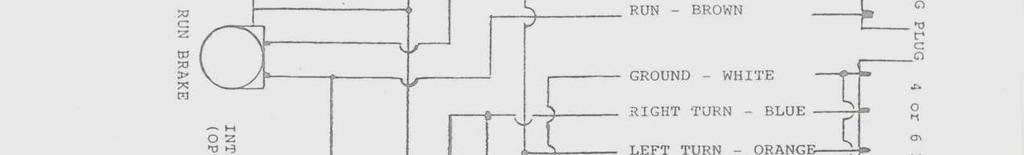
15 mufflers are installed, you will place tips back on muffler and align in the cut out section of trike body and pop rivet into place Now you will reinstall both passenger footrests and bottom plates. (Removed in Step 1.5). Next install wheels to rear axles and torque lug nuts to 75 ft. lbs. Place center caps on rim and tighten support screws In front of tour box is a row of connectors. Locate green plug and strip back 1 of tape around wires. Using a quick splice, connect both outside wires together. (Green wire and red with a white tracer.) Now the tour box and the seat can be reinstalled in that order. Reconnect all electrical and antenna connections. It will be necessary to remove chrome license plate light cover to allow clearance for trunk door to open If using stock turn downs for years 88 97, insert turn downs back into mufflers and turn each one towards tire on same side and drill two (2) 3 /16 holes and secure with pop rivets. If using California Sidecar Exhaust triple turndowns, slide over end of muffler and tighten clamp bolts Route release cables (installed in Step 10.2) back up into tour box and connect to release levers. Now you can connect release cables to the release rod in trunk using black extension clips supplied with kit. With clips installed, run cable ties around release rod and through these black extension clips and adjust cable tension for optimum operation of trunk release. (NOTE: TOUR model uses the Honda OEM clips.) 12. INSTALLING TRAILER HITCH & WIRING Position hitch plate into frame and install all support bolts and tighten. Locate a 1 /8 or 3 /16 X 8 drill bit. From the underside of the trike, and using the four corners of the receiver as a guide, drill four (4) holes through the fiberglass body (one at each corner of the receiver). Then, from outside of body, use a ruler and scribe to connect the four (4) holes you drilled. Cut out with a grinder. After cutting out, use flat file to smooth edges. Loosen lock bolt on hitch plate, slide tongue into position, fasten with clip and pin, and re-tighten lock bolt. Now you can install hitch ball and tighten to 50 ft. lbs Refer to Wiring Schematic on p. 16. CAUTION: All California Sidecar Trikes are pre-wired to accommodate the Escapade Trailer wire harness. California ia Sidecar is not responsible for any modification to this wire harness or schematic. 13. INSTALLING FRONT WHEEL CROSSOVER BRAKE LINE
16 13.1 (Refer back to Step 2.2). Remove both brake lines from calipers. Save left banjo bolt for later use. Route new cross over line from right caliper to left. Using new double banjo bolt supplied, install in this order: banjo bolt, crush washer, OEM brake line, crush washer, cross over line, crush washer, then screw into right caliper. On the left: OEM banjo bolt; crush washer; cross over line; crush washer; then screw into left caliper. The OEM brake line will be cut at frame next to lower triple tree and then discarded or the brake line may be tied out of the way. 14. INSTALLING NEW FRONT BRAKE MASTER CYLINDER 14. Step 14 of these instructions is related to the installation of the front brake master cylinder, which has been modified to accept a larger piston for more efficient braking. The modification cost is included in the purchase price, however, because there are several different types of GL1500 master cylinders, it is necessary for you to send us your master cylinder so we are able to match your specific type and return a modified part. It will be returned to you via UPS 2-day service within 24 hours after we receive it. Please drain all brake fluid and remove all parts except the stainless steel protector covering the bleed hole inside the fluid reservoir. Also, include a copy of your order invoice which indicates the ORDER ID so that we are able to identify the master cylinder and your return address. We appreciate your cooperation. Questions? Please call the Parts & Service Dept Return to: California Sidecar 100 Motorcycle Run Arrington, VA Attention: MASTER CYLINDER 14.1 Remove plastic cap over master cylinder support bolts. Remove lever and banjo bolt with brake line and brake light switch. Do not lose crush washers. Remove two (2) support bolts that hold master cylinder to handle bar. Please drain all brake fluid and a remove all parts except the stainless steel protector covering the bleed hole inside the fluid reservoir Now, in reverse order, reinstall new master cylinder to handle bar. Reinstall brake line and lever removed from previous step. Tighten brake line at three (3) places: master cylinder, right and left calipers Fill reservoir with clean DOT 3 or DOT4 fluid and let stand for 10 minutes at room temperature (longer if colder). Next, bleed at: 1) left front, 2) right front, and 3) master cylinder. Let sit again as noted above then repeat as necessary until all air is removed. Refill reservoir and replace cap. Reinstall both brake rotor covers. (Removed in Step 2.2). IMPORTANT! The brakes must be seated properly, before riding in traffic. Until the brakes are seated, there will be reduced braking power. To seat them, tap on the brake pedal for several miles, causing them to heat up. Stop and allow them to cool down. 13


17 14
18 15
19 16
CALIFORNIA SIDECAR TRIKE CONVERSION KIT INSTALLATION INSTRUCTIONS VALKYRIE INTERSTATE
 CALIFORNIA SIDECAR TRIKE CONVERSION KIT INSTALLATION INSTRUCTIONS VALKYRIE INTERSTATE FOR INSTALLATION ASSISTANCE, CALL PARTS & TECHNICAL SUPPORT @ (434) 263-8866 TABLE OF CONTENTS SECTION PAGE Table of
Trike Conversion Kit GL1500 Goldwing
 BY Trike Conversion Kit 1988-2000 GL1500 Goldwing Installation Instructions Revised 3-2018 California Sidecar Parts & Technical Support 434.263.8866 Table of contents: 1. Maintenance Schedule 5 2. Disassembly
Installation Instructions
 By Trike Conversion Kit for INDIAN MOTORCYCLES CLASSIC - VINTAGE - DARKHORSE CHIEFTAN & ROADMASTER MODELS 2014 - CURRENT Installation Instructions Revised 4-2017 California Sidecar Parts & Technical Support
Victory CrossRoads CrossCountry CrossCountry Tour HardBall
 by Trike Conversion Kit Victory CrossRoads CrossCountry CrossCountry Tour HardBall Installation Instructions Revised 3-2018 California Sidecar Parts & Technical Support 434.263.8866 Table of Contents:
Current. Installation Instructions
 by Trike Conversion Kit 2004 - Current Harley-Davidson Sportster Installation Instructions REVISED 4-2017 California Sidecar Parts & Technical Support 434.263.8866 Table of contents: 1. Warnings and Considerations
Installation Instructions
 BY Trike Conversion Kit KAWASAKI Vulcan 900 CLASSIC- CLASSIC LT AND CUSTOM MODELS 2006-CURRENT Installation Instructions Revised 1-2015 California Sidecar Parts & Technical Support 434.263.8866 2 Table
Trike Conversion Kit ROADLINER, STRATOLINER, & STRATOLINER DELUXE
 by Trike Conversion Kit ROADLINER, STRATOLINER, & STRATOLINER DELUXE Installation Instructions Revised 1-2015 California Sidecar Parts & Technical Support 434.263.8866 Table of Contents: 1. Warnings and
Trike Conversion Kit. KAWASAKI 1700 Vulcan Voyager Vulcan Vaquero Vulcan Nomad. Installation Instructions
 BY Trike Conversion Kit KAWASAKI 1700 Vulcan Voyager Vulcan Vaquero Vulcan Nomad Installation Instructions REVISED 1-2015 California Sidecar Parts & Technical Support 434.263.8866 Table of Contents: 1.
2018 UP GL1800 Gold Wing & Gold Wing Tour. Trike Kit Installation Instructions. California Sidecar Parts & Technical Support
 by 2018 UP GL1800 Gold Wing & Gold Wing Tour Trike Kit Installation Instructions California Sidecar Parts & Technical Support 434.263.8866 2 Table of contents: 1. Maintenance Schedule 5 2. Disassembly
Cobra & Cobra XL. Trike Conversion Kit GL1800 Goldwing. Installation Instructions. California Sidecar Parts & Technical Support
 Cobra & Cobra XL by Trike Conversion Kit 2001-2010 GL1800 Goldwing Installation Instructions REVISED 1-2015 California Sidecar Parts & Technical Support 434.263.8866 Table of contents: 1. Maintenance Schedule
2018 UP GL1800 Gold Wing & Gold Wing Tour. Power Trak Installation Instructions. California Sidecar Parts & Technical Support
 by 2018 UP GL1800 Gold Wing & Gold Wing Tour Power Trak Installation Instructions California Sidecar Parts & Technical Support 434.263.8866 Warnings and considerations: 1. Disclaimer - These instructions
Trike Conversion Kit GL1800 Goldwing Current. Installation Instructions
 by Trike Conversion Kit GL1800 Goldwing 2012 - Current Installation Instructions REVISED 4-2015 California Sidecar Parts & Technical Support 434.263.8866 Table of contents: 1. Maintenance Schedule 5 2.
Cobra & Cobra XL. Power Trak Current GL1800 Goldwing. Installation Instructions. California Sidecar Parts & Technical Support
 Cobra & Cobra XL by 2001 - Current GL1800 Goldwing Power Trak 6 Installation Instructions REVISED 1 2015 California Sidecar Parts & Technical Support 434.263.8866 Warnings and considerations: 1. Disclaimer
Installation Instructions
 BY Trike Conversion Kit 2009 - Current FLHT Series Harley-Davidson Installation Instructions REVISED 7-2017 California Sidecar Parts & Technical Support 434.263.8866 2 Table of contents: 1. Warnings and
2018 UP GL1800 Gold Wing & Gold Wing Tour. Auxiliary Fuel Tank. Installation Instructions
 by 2018 UP GL1800 Gold Wing & Gold Wing Tour Auxiliary Fuel Tank Installation Instructions California Sidecar Parts & Technical Support 434.263.8866 Warnings and considerations: 1. Disclaimer - These instructions
R O A D S M I T H TRIKE CONVERSIONS BY THE TRIKE SHOP
 R O A D S M I T H TRIKE CONVERSIONS BY THE TRIKE SHOP Please thoroughly review the instructions before and during installation. Keep in mind that this product was designed to be installed by trained dealer
Trike Conversion Installation Guide Kawasaki Vulcan 900 Classic, Classic LT, and Custom Models 2007 and Up Solid Axle Suspension
 Trike Conversion Installation Guide Kawasaki Vulcan 900 Classic, Classic LT, and Custom Models 2007 and Up Solid Axle Suspension CAUTION: -Failure to make the proper adjustments will potentially lead to
Installation Instructions
 BY Trike Conversion Kit 1999 2008 FLHT Series Harley-Davidson Installation Instructions REVISED 4-2017 California Sidecar Parts & Technical Support 434.263.8866 Table of contents: 1. Warnings and considerations
R O A D S M I T H TRIKE CONVERSIONS BY THE TRIKE SHOP
 R O A D S M I T H TRIKE CONVERSIONS BY THE TRIKE SHOP Please thoroughly review the instructions before and during installation. Keep in mind that this product was designed to be installed by trained dealer
R O A D S M I T H TRIKE CONVERSIONS BY THE TRIKE SHOP
 R O A D S M I T H TRIKE CONVERSIONS BY THE TRIKE SHOP Please thoroughly review the instructions before and during installation. Keep in mind that this product was designed to be installed by trained dealer
Slave Cylinder Weep Hole Drilling Procedure
 Slave Cylinder Weep Hole Drilling Procedure Tools Required: T20 Torx Driver T25 Torx Driver T25 Torx Bit with ¼ Ratchet Wrench 4mm Hex Key (Allen wrench) 5mm Hex Key 6mm Hex Key 8mm Hex Key 12mm Hex Key
Deuce/Ace Installation Instructions
 HARDWARE KIT: Upper Mounting Plate: 2-7/16" (11mm) X 3.5" bolts 2-7/16" flange nuts 2-2" spacers 2-7/16" trim cap mounting washers 2 - plastic trim caps TOOLS NEEDED: safety glasses wrenches 16mm or 5/8"
INSTALLATION INSTRUCTIONS FOR THE TOMAHAWK ELECTRIC REVERSE
 INSTALLATION INSTRUCTIONS FOR THE TOMAHAWK ELECTRIC REVERSE LAST UPDATED: April 2018 Thank you for choosing the Motor Trike Electric Reverse. We ask that you read the directions before you start and follow
Trike Conversion Installation Manual. All Models
 Trike Conversion Installation Manual For Honda VTX 1300 Motorcycles All Models Revision 4 Mar. 2011 CAUTION: Failure to follow these instructions can lead to serious personal injury and/or property damage
R O A D S M I T H TRIKE CONVERSIONS BY THE TRIKE SHOP
 R O A D S M I T H TRIKE CONVERSIONS BY THE TRIKE SHOP Please thoroughly review the instructions before and during installation. Keep in mind that this product was designed to be installed by trained dealer
R O A D S M I T H TRIKE CONVERSIONS BY THE TRIKE SHOP
 R O A D S M I T H TRIKE CONVERSIONS BY THE TRIKE SHOP Please thoroughly review the instructions before and during installation. Keep in mind that this product was designed to be installed by trained dealer
Trike Conversion Installation Guide for Harley-Davidson Sportster Motorcycles 2004 & Up Revision 7
 Trike Conversion Installation Guide for Harley-Davidson Sportster Motorcycles 2004 & Up Revision 7 CAUTION : Failure to follow these instructions can lead to serious personal injury and/or property damage
Trike Conversion Installation Guide for Indian Scout Motorcycles 2016 & Up Revision 2
 Trike Conversion Installation Guide for Indian Scout Motorcycles 2016 & Up Revision 2 Warning - This product was not intended for more than one rider. Weight limit on this product has been set at 400 lbs.
Installation Instructions
 By ELECTRIC REVERSE INDIAN MOTORCYCLES CLASSIC - VINTAGE - DARKHORSE CHIEFTAN & ROADMASTER MODELS 2014 - CURRENT Revised 10-2018 Installation Instructions California Sidecar Parts & Technical Support 434.263.8866
'99-03 CHEVROLET/GMC IFS 4WD 6" SUSPENSION SYSTEM P/N INSTALLATION INSTRUCTIONS
 1/16/04 '99-03 CHEVROLET/GMC IFS 4WD 6" SUSPENSION SYSTEM P/N. 10-41099 INSTALLATION INSTRUCTIONS NOTE: Each Lift Kit and options to Lift Kits are packaged separately. Therefore, installation procedures
INSTALLATION INSTRUCTIONS
 INSTALLATION INSTRUCTIONS REAR DISC BRAKE CONVERSION KIT A126-1 1973-87 CHEVROLET 1/2 TON 2WD Thank you for choosing STAINLESS STEEL BRAKES CORPORATION for your braking needs. Pleases take the time to
GL1800 TRAILER HITCH - INSTALLATION INSTRUCTIONS #GL
 GL1800 TRAILER HITCH - INSTALLATION INSTRUCTIONS #GL18007-20 Read through these instructions completely before attempting installation, lay out all pieces including the numbered hardware bags to familiarize
Suspension System RS6582B
 Suspension System RS6582B Tahoe/Yukon READ ALL INSTRUCTIONS THOROUGHLY FROM START TO FINISH BEFORE BEGINNING INSTALLATION IMPORTANT NOTES! WARNING: This suspension system will enhance the off-road performance
ALL DIRECTIONS/REVISIONS WERE COMPILIED ON
 R O A D S M I T H TRIKE CONVERSIONS Please thoroughly review the instructions before and during installation. Keep in mind that this product was designed to be installed by trained dealer technicians.
INSTALLATION INSTRUCTIONS
 INSTALLATION INSTRUCTIONS REAR DISC BRAKE CONVERSION KIT A158 1994-97 Dodge Ram 1500 (2WD & 4WD) and REAR DISC BRAKE CONVERSION KIT A158-1 1998-01 Dodge Ram 1500 (2WD & 4WD) Thank you for choosing STAINLESS
2010+ Victory Cross Country / Cross Roads Installation Guide Nov 2014
 2010+ Victory Cross Country / Cross Roads Installation Guide Nov 2014 125 Industrial Drive Spearfish, SD 57783 Toll Free 888.3WHEELS w w w. l e h m a n t r i k e s. c o m UNDERSTANDING SAFETY LABELS &
INSTALLATION INSTRUCTIONS FOR THE MOTOR TRIKE GL1500 RAKE KIT
 INSTALLATION INSTRUCTIONS FOR THE MOTOR TRIKE GL1500 RAKE KIT Thank you for choosing the Motor Trike GL1500 Rake Kit. We ask that you read the directions before you start and follow them very closely.
INSTALLATION INSTRUCTIONS 97 FORD EXPEDITION
 INSTALLATION INSTRUCTIONS 97 FORD EXPEDITION 1. Read the instructions completely and carefully before you begin. Check the kit for proper contents (refer to the part s list and the picture diagrams). Before
INSTALLATION INSTRUCTIONS
 INSTALLATION INSTRUCTIONS REAR DISC BRAKE CONVERSION KITS A112, A112-1 & A112-93 1979-93 FORD MUSTANG with 7.5" & 8.8" AXLES Thank you for choosing STAINLESS STEEL BRAKES CORPORATION for your braking needs.
RAIDER to 2016 XL MODELS *Will not fit XR1200 models *Nightster, Forty-Eight and Iron 883 models may require additional modifications
 RAIDER 2014 to 2016 XL MODELS *Will not fit XR1200 models *Nightster, Forty-Eight and Iron 883 models may require additional modifications **Installation should be installed by a qualified mechanic INSTALLATION
INSTALLATION INSTRUCTIONS
 INSTALLATION INSTRUCTIONS REAR DISC CONVERSION KIT A126-2 1988-98 C1500 2WD 10" REAR DRUM Thank you for choosing STAINLESS STEEL BRAKES CORPORATION for your braking needs. Pleases take the time to read
R O A D S M I T H TRIKE CONVERSIONS BY THE TRIKE SHOP
 R O A D S M I T H TRIKE CONVERSIONS BY THE TRIKE SHOP Please thoroughly review the instructions before and during installation. Keep in mind that this product was designed to be installed by trained dealer
P/N Instr Rev Page 1 of 11
 BRAKE AND CLUTCH KIT P/N 2883864 IMPORTANT Due to the technical nature of this kit, Indian Motorcycle insists this installation be performed by a certified Indian Motorcycle Technician. APPLICATION Verify
SPORTSTER SADDLEBAG KIT. i i02212
 General These saddlebags are designed to fit 99 and later Sportster Model Motorcycles, except XL00 Sport models with gas reservoir shock absorbers and 88R models. See the Service Parts pages for a list
05-08 GT. Hellion Power Systems Mustang Kit Instructions
 Hellion Power Systems 05-08 Mustang Kit Instructions 1. Disconnect Battery 2. Drain Radiator, keep fluid for re-installation. 3. Remove air box and inlethoses. 6. Next, underneath, punch oil pan for turbo
INSTALLATION INSTRUCTIONS
 INSTALLATION INSTRUCTIONS REAR DISC BRAKE CONVERSION KIT A157 1991-2004 Dodge Dakota 2WD 1991-2002 Dodge Dakota 4WD 1998-2002 Dodge Durango Thank you for choosing STAINLESS STEEL BRAKES CORPORATION for
RHINO SUSPENSION SYSTEM INSTALLATION INSTRUCTIONS
 PARTS INCLUDED: 2 FRONT UPPER A-ARMS 2 FRONT LOWER A-ARMS 2 UNI-BALL JOINTS 2 UNI-BALL JOINT STUDS 2 UNI-BALL JOINT CAPS 2 RETAINING RINGS 1 FRONT SHOCK ASSEM. 2 DELRON STEERING STOPS 2 SHOCK MOUNT SPACERS
Installation Notes: #86000-R Race Series +3.5 L/T Kit
 159 North Maple St. Unit J, CORONA CA 92880 P. 951-737-9682 F. 951-737-9006 WWW.CHAOSFAB.COM Installation Notes: #86000-R Race Series +3.5 L/T Kit Factory manual is recommended for removal and re-installation
INSTALLATION INSTRUCTIONS
 INSTALLATION INSTRUCTIONS FORCE 10 SPORT R1 REAR DISC CONVERSION KIT A126-50 2005-10 Chevrolet Silverado and GMC Sierra Thank you for choosing STAINLESS STEEL BRAKES CORPORATION for your braking needs.
INSTALLATION INSTRUCTIONS
 INSTALLATION INSTRUCTIONS REAR DISC BRAKE CONVERSION KIT A126-3 1988-98 CHEVY K1500 4WD 10" DRUMS Thank you for choosing STAINLESS STEEL BRAKES CORPORATION for your braking needs. Pleases take the time
INSTALLATION INSTRUCTION 88581
 INSTALLATION INSTRUCTION 88581 FOR RANCHO SUSPENSION SYSTEM RS6581B: DODGE RAM READ ALL INSTRUCTIONS THOROUGHLY FROM START TO FINISH BEFORE BEGINNING INSTALLATION Rev C IMPORTANT NOTES! WARNING: This suspension
Installation Instructions
 Installation Instructions Rear Disc Brake Conversion Kit Item # RC1001, RC1001X Applications: 64-72 A-body, 67 F-Body, 63-67 X-body with Non Staggered Shocks Thank you for choosing GPS Auto for your automotive
INSTALLATION INSTRUCTIONS
 INSTALLATION INSTRUCTIONS COMP. R AND COMP. S QUICK CHANGE KITS A200, A200-1 Thank you for choosing STAINLESS STEEL BRAKES CORPORATION for your braking needs. Pleases take the time to read and carefully
FAX
 INSTALLATION INSTRUCTIONS 6090 Air Suspension Kit (pat. pending) 1999-2006 Tahoe, Suburban, Avalanche, Yukon Thank you for purchasing a quality Hellwig Product. PLEASE READ THIS INSTRUCTION SHEET COMPLETELY
INSTALLATION INSTRUCTION 88094
 INSTALLATION INSTRUCTION 88094 FOR RANCHO SUSPENSION SYSTEM RS6594B 4WD & 2WD NISSAN TITAN READ ALL INSTRUCTIONS THOROUGHLY FROM START TO FINISH BEFORE BEGINNING INSTALLATION Rev D IMPORTANT NOTES! WARNING:
INSTALLATION INSTRUCTIONS
 INSTALLATION INSTRUCTIONS 2005-2012 Nissan Xterra/Frontier / Pathfinder PART NUMBERS: NP17500, NP17525, NP17550 FRONTIER PARTS & CORRESPONDING HARDWARE LIST XTERRA PATHFINDER ABOVE LISTED 1/2 Metal Lock
Engine Removal/Installation
 Engine Removal/Installation Make sure jacks and safety stands are placed properly and hoist brackets are attached to correct positions on the engine. (See Section 1). Apply parking brake and block rear
Factory Five Racing, Inc. Roadster Complete Kit Assembly manual revision 3p update
 Factory Five Racing, Inc. Roadster Complete Kit Assembly manual revision 3p update Kit Parts Prep...3 Body Removal...3 Aluminum Removal...5 Front upper control arm...7 Adjusting the upper control Arm...10
ELECTRIC REVERSE Installation Instructions
 BY 1999 - Current FLHT Series Harley-Davidson ELECTRIC REVERSE Installation Instructions REVISED 1-2016 California Sidecar Parts & Technical Support 434.263.8866 Warnings and considerations: 1. Disclaimer
Z-Gate Universal Shifter
 Installation Instructions Z-Gate Universal Shifter Fits: GM, Ford, Lincoln and Chrysler Transmissions See Application Guide for Specific Applications Part #80681 Rev 06/01/2018 WORK SAFELY! For maximum
Installation Instructions Z-Gate Shifter
 Installation Instructions Z-Gate Shifter Part Number 80681 1998, 2001 by B&M Racing and Performance Products The B&M Z-Gate shifter can be used in vehicles equipped with most popular three speed automatic
INSTALLATION INSTRUCTIONS Part# , , ,
 INSTALLATION INSTRUCTIONS Part# 20-0218, 22-0318, 20-0118, 22-0219 20-0218 - 4 Tire On Board Air Delivery System and Dual Compressed Air System Includes ARB CKMTA12 Compressor 20-0118 - 2017 FORD RAPTOR
INSTALLATION INSTRUCTIONS
 INSTALLATION INSTRUCTIONS REAR DISC BRAKE CONVERSION KIT A125-2 1955-70 FULL SIZE CHEVROLET Thank you for choosing STAINLESS STEEL BRAKES CORPORATION for your braking needs. Pleases take the time to read
LPE C5 Battery Relocation Kit
 LPE C5 Battery Relocation Kit The LPE C5 Corvette battery relocation kit improves vehicle weight distribution by moving weight to the rear of the vehicle. The improved weight distribution increases traction
INSTALLATION INSTRUCTIONS
 INSTALLATION INSTRUCTIONS FUEL SURGE TANK INSTALL KIT Honda S2000 Document# 19-0063 Support: info@radiumauto.com WARNING: DO NOT SMOKE WHILE WORKING ON FUEL SYSTEMS. KEEP SPARKS AND OPEN FLAMES AWAY FROM
INSTALLATION PROCESS: FK003D945-7 Complete Front, Rear, and Clutch A.B.S. KIT Harley Davidson FLH Touring Models
 INSTALLATION PROCESS: FK003D945-7 Complete Front, Rear, and Clutch A.B.S. KIT 2014-2017 Harley Davidson FLH Touring Models Parts List: 4 Lines 1 Brake Light Switch Adapter 7 Single banjo bolts 2 Caliper
INSTALLATION INSTRUCTIONS FOR THE MOTOR TRIKE CROSS COUNTRY / CROSS ROADS / HARD BALL RAKE KIT
 INSTALLATION INSTRUCTIONS FOR THE MOTOR TRIKE CROSS COUNTRY / CROSS ROADS / HARD BALL RAKE KIT Thank you for choosing the Motor Trike Cross Country / Cross Roads / Hard Ball rake kit. We ask that you read
Installation instructions, accessories - Fuel driven heater 912-D
 XC90 Section Group Weight(Kg/Pounds) Year Month 8 87 2002 10 XC90 2003 D5244T, XC90 2004 D5244T, XC90 2005 D5244T AW50/51 AWD, XC90 2006 D5244T, XC90 2006 D5244T AW50/51 AWD D5244T R8703687 Page 1 of 20
INSTALLATION INSTRUCTIONS
 INSTALLATION INSTRUCTIONS DISC BRAKE CONVERSION KITS A120-4 & A120-5 1964-1/2-66 Ford & Mercury Thank you for choosing STAINLESS STEEL BRAKES CORPORATION for your braking needs. Pleases take the time to
-Failure to make the proper adjustments will potentially lead to serious personal injury and/or property damage and may void the warranty.
 Trike Conversion Installation Guide Victory Cross Roads Classic and 8-Ball Victory Cross Country/Tour/8-Ball and Ness Cross Country Limited-Edition and Up Independent Suspension Rev. 1 CAUTION: -Failure
Trike Conversion Installation Guide for Zero Flex Solid Axle Wide Body Harley-Davidson FLH Series Motorcycles Revision 1
 Trike Conversion Installation Guide for Zero Flex Solid Axle Wide Body Harley-Davidson FLH Series Motorcycles 2014-2016 Revision 1 WARNING: Failure to follow these instructions can lead to serious personal
DISC BRAKE/DUAL MASTER CYLINDER CONVERSION. Tools, Equipment and Supplies Needed:
 Please take the time to read the enclosed instructions carefully. If you have any questions, call our Product Assistance personnel for clarification. It is important to note that these instructions contain
18SP680Rev3 EPA04 MBE 4000 Car Hauler Low Pressure Fuel Lines
 8SP680Rev3 EPA04 MBE 4000 Car Hauler Low Pressure Fuel Lines KIT DESCRIPTION These service kits include all necessary parts to replace the low pressure fuel lines between the fuel filter housing and fuel
OIL COOLER KIT INSTALLATION INSTRUCTIONS PART NUMBER D
 OIL COOLER KIT INSTALLATION INSTRUCTIONS PART NUMBER D570-0907 APPLICATION: 2011-12 E90 335i/xi (N55 engine) with BMW M-Technic bumper and without stock oil cooler Congratulations for being selective enough
INSTALLATION INSTRUCTIONS
 INSTALLATION INSTRUCTIONS PERFORMANCE AT THE WHEELS KIT W125-42 GM 10 & 12 Bolt Rear Axles with Staggered or non-staggered Shocks with C-Clips Thank you for choosing STAINLESS STEEL BRAKES CORPORATION
INSTALLATION INSTRUCTIONS
 INSTALLATION INSTRUCTIONS REAR DISC BRAKE CONVERSION KIT A125-3 1965-72 GM A-BODY 10 & 12 BOLT AXLES Thank you for choosing STAINLESS STEEL BRAKES CORPORATION for your braking needs. Pleases take the time
X4 (GREEN) (A2000ATF2AUSG) Page 1 of 80 AIR INTAKE ASSEMBLY
 (A2000ATF2AUSG) Page 1 of 80 AIR INTAKE ASSEMBLY") 2000 300 2X4 (GREEN) (A2000ATF2AUSG) Page 1 of 80 AIR INTAKE ASSEMBLY 2000 300 2X4 (GREEN) (A2000ATF2AUSG) Page 2 of 80 AIR INTAKE ASSEMBLY Ref # Part Number Qty S/P/F Description 1 3570-001 1 /P Intake,
2000 300 2X4 (GREEN) (A2000ATF2AUSG) Page 1 of 80 AIR INTAKE ASSEMBLY 2000 300 2X4 (GREEN) (A2000ATF2AUSG) Page 2 of 80 AIR INTAKE ASSEMBLY Ref # Part Number Qty S/P/F Description 1 3570-001 1 /P Intake,
w w w. h d o n l i n e s h o p. d e CRUISE CONTROL KIT GENERAL INSTALLATION -J04064 REV Kit Number Models Additional Parts Required
 -J006 REV. 006-08- CRUISE CONTROL KIT GENERAL Kit Number 7796-07 Models For the most up-to-date model fitment information, please see the product label or www.harley-davidson.com. Additional Parts Required.
INSTALLATION INSTRUCTIONS
 INSTALLATION INSTRUCTIONS FUEL SURGE TANK INSTALLATION KIT 1999-2006 BMW E46 COUPE Document# 19-0056 Support: info@radiumauto.com Note: This kit was designed for a standard single pump Radium Engineering
99-04 GT. Hellion Power Systems Mustang GT Kit Instructions
 Hellion Power Systems 99-04 Mustang GT Kit Instructions Part 1 Hellion recommends that the front suspension system be installed either by trained professionals or by 5.Remove rack bolts K-Member Installation
OIL COOLER KIT INSTALLATION INSTRUCTIONS PART NUMBER D E92 335i/xi without stock oil cooler
 OIL COOLER KIT INSTALLATION INSTRUCTIONS PART NUMBER D570-0921 APPLICATION 2007-08 E92 335i/xi without stock oil cooler Congratulations for being selective enough to use a Dinan Engineering Oil Cooler
INSTALLATION INSTRUCTIONS
 INSTALLATION INSTRUCTIONS PERFORMANCE AT THE WHEELS KIT W155-5 CHRYSLER 8 3 /4" & 9 3 /4" REAR AXLES Thank you for choosing STAINLESS STEEL BRAKES CORPORATION for your braking needs. Please take the time
INSTALLATION INSTRUCTIONS FUEL SURGE TANK KIT
 INSTALLATION INSTRUCTIONS FUEL SURGE TANK KIT BMW E46 3-Series, Excl Convertible Document: 19-0056 Support: info@radiumauto.com Relieve fuel pressure in vehicle before beginingthe installation. Disconnect
*1576BAG9* 1576BAG FORD F KIT C THANK YOU FOR CHOOSING ROUGH COUNTRY FOR YOUR SUSPENSION NEEDS.
 957600C THANK YOU FOR CHOOSING ROUGH COUNTRY FOR YOUR SUSPENSION NEEDS. 0-08 FORD F50-6 KIT Rough Country recommends a certified technician install this system. In addition to these instructions, professional
INSTALLATION INSTRUCTIONS
 INSTALLATION INSTRUCTIONS DISC BRAKE CONVERSION KITS A121-1, A121-2, A121-3, A121-4 1967-69 Ford & Mercury Thank you for choosing STAINLESS STEEL BRAKES CORPORATION for your braking needs. Pleases take
04-08 FORD F150 4 KIT
 9257700 04-08 FORD F50 4 KIT THANK YOU FOR CHOOSING ROUGH COUNTRY FOR YOUR SUSPENSION NEEDS. Rough Country recommends a certified technician install this system. In addition to these instructions, professional
Installation Guide. Yamaha. 40 Sport Trike Kit All Years
 Installation Guide Yamaha 40 Sport Trike Kit All Years INCLUDED IN YOUR TRIKE KIT: COMPONENTS Frankenstein Trikes Rear End Swing Arm Body Body Mounting Bracket 10 lug nuts 1 2 American Eagle 15 X 8 wheels
INSTALLATION INSTRUCTIONS
 HIGH FLOW AIRFLOW METER INSTALLATION INSTRUCTIONS PART NUMBER D763-1600A APPLICATION: 2001-06 E46 M3 Parts List: Hose clamp 64Z (7) Plastic Rivets Air Filter Temp Sensor & Harness (2) Button Head Screws
INSTALLATION INSTRUCTION 89400
 INSTALLATION INSTRUCTION 89400 FOR RANCHO SUSPENSION SYSTEM RS66400B: 2012 RAM 1500 4WD. READ ALL INSTRUCTIONS THOROUGHLY FROM START TO FINISH BEFORE BEGINNING INSTALLATION Rev B IMPORTANT NOTES! WARNING:
INSTALLATION INSTRUCTIONS
 INSTALLATION INSTRUCTIONS REAR DISC CONVERSION KIT A136-1 1976-86 AMC 20 AXLES WITH WARN FULL FLOATING AXLE CONVERSION Thank you for choosing STAINLESS STEEL BRAKES CORPORATION for your braking needs.
ZX-14 Stage I Turbo Kit
 62910 Peerless Ct. Bend, OR 97701 Phone 541.385.0706 Fax 541.382.9406 ZX-14 Stage I Turbo Kit WARNING: This turbo kit is for OFF-ROAD RACING use ONLY. Advisement: These instructions are written to be comprehensive
Sport S/T3 Suspension Installation Guide
 1 Sport S/T3 Suspension Installation Guide #1258250-JK 2-Door Sport S/T3 (No Shocks) #1258200-JK 2-Door Sport S/T3 (w/ Fox Shocks) #1258450-JK 4-Door Sport S/T3 (No Shocks) #1258400-JK 4-Door Sport S/T3
07-UP AVALANCHE 7.5 KIT
 92120900R1 07-UP AVALANCHE 7.5 KIT Thank you for choosing Rough Country for your suspension needs. We appreciate your business!! This kit will not fit vehicles equipped with electric steering or trucks
'88-'00 CHEVROLET/GMC IFS 4WD(8LUG) OLD BODY STYLE 6" SUSPENSION SYSTEM P/N
 OLD BODY STYLE 6 SUSPENSION SYSTEM P/N") 4/10/13 '88-'00 CHEVROLET/GMC IFS 4WD(8LUG) OLD BODY STYLE 6" SUSPENSION SYSTEM P/N. 10-41888 INSTALLATION INSTRUCTIONS APPLICATION WARNING: Applicable for hub mounted ABS sensor models only. Not for 1992-94
4/10/13 '88-'00 CHEVROLET/GMC IFS 4WD(8LUG) OLD BODY STYLE 6" SUSPENSION SYSTEM P/N. 10-41888 INSTALLATION INSTRUCTIONS APPLICATION WARNING: Applicable for hub mounted ABS sensor models only. Not for 1992-94
REAR STEEL BUMPER INSTALLATION INSTRUCTIONS Runner
 REAR STEEL BUMPER INSTALLATION INSTRUCTIONS 2010+ 4Runner Version 2.1.0 - September 2016 Thank you for purchasing the Southern Style OffRoad Toyota 4Runner 5 th Gen Modular Rear Plate Steel Bumper. It
8436, 8437, 8438, 8439, 8442, 27480, 27780, 28028, & ISOLATION MODULE ELECTRICAL SYSTEM
 September 11, 2003 Lit. No. 27808 8436, 8437, 8438, 8439, 8442, 27480, 27780, 28028, & 28400 ISOLATION MODULE ELECTRICAL SYSTEM Installation Instructions Read this document before installing the snowplow.
<THESE INSTRUCTIONS MUST BE GIVEN TO THE END USER> B&W
 B&W Trailer Hitches 6 Hawaii Rd / PO Box 86 Humboldt, KS 66748 P:60.473664 F:60.869.903 Turnoverball Gooseneck Hitch Installation Instructions MODEL 08
29048, 29049, 29050, 29051, 29052, 29053, 29054,
 May 1, 2018 Lit. No. 29206, Rev. 13 29048, 29049, 29050, 29051, 29052, 29053, 29054, 29400 7 HARNESS KIT 3 PORT ISOLATION MODULE LIGHT SYSTEM w/3 PLUG SYSTEM HARNESSES Installation Instructions Read this
80-96 Ford F150 / Bronco 4WD Class II 4"- 6" Suspension Lift Installation Instructions
 www.skyjacker.com Required Tool List: 80-96 Ford F150 / Bronco 4WD Class II 4"- 6" Suspension Lift Installation Instructions Safety Glasses Metric / Standard Wrenches & Sockets Floor Jack Jack Stands Measuring
INSTALLATION INSTRUCTIONS
 INSTALLATION INSTRUCTIONS FX4 ELITE REAR DISC CONVERSION KITS WITH INTERNAL PARKING BRAKE A110-14, A111-25, A111-29 for FORD 8" & 9" REAR ENDS Thank you for choosing STAINLESS STEEL BRAKES CORPORATION