Enabling Switches Grip Style Enabling Switches
|
|
|
- Roger Strickland
- 6 years ago
- Views:
Transcription

1 Enabling es Grip Style Enabling es


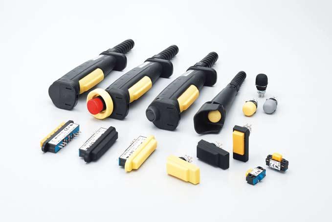
2 What is an enabling switch? Because operators use teach pendants in hazard ous environments performing teaching, system changeover, and maintenance of robots, they must have protection against unpredictable motion of robots, and therefore teach pendants are equipped with 3-position enabling switches. An enabling switch is a 3-position (OFF-ON-OFF) switch to allow a machine operation only when the switch is lightly pressed and held in the mid posi tion (position 2). Because it disables machine operation when released (position 1) or further depressed (position 3) by a panicked operator, the safety of operators using teach pendants or grip style enabling switches in hazardous environments is ensured. HG2S CC Pendant HE1G/HE1G-L/HE2G Grip Style Back of the HG2S CC Pendant HE1G/HE1G-L Two HE1B Enabling es inside HE2G HG1H/1T Small Teaching Pendant HE9Z-GSH51 Grip Style Enabling Housing + HE5B Enabling HG1H HG1T 2
: When an enabling device is provided as a part of a sys tem, it shall be designed to allow motion when actuated in one position only. In any other position motion shall be stopped.")
 When returning from position 3 to position 2, the function shall be ended. Position 1 Position 2 Position 3 Terminal Contact 1. Press lightly 3.")
 is required when an operator works near a hazard inside a safety guard.")
3 Operation of enabling switches The requirement for operation of 3-position enabling switches (according to IEC ; ): When an enabling device is provided as a part of a sys tem, it shall be designed to allow motion when actuated in one position only. In any other position motion shall be stopped. for a three-position type: position 1: off-function of the switch (actuator is not operated) position 2: enabling function (actuator is operated in its mid position) position 3: off-function (actuator is operated past its mid position) When returning from position 3 to position 2, the function shall be ended. Position 1 Position 2 Position 3 Terminal Contact 1. Press lightly 3. Press tightly Movable Contact ON OFF 2. Release OFF 4. Release Disparity detection of two contacts A high level of safety safety category 3 or higher (ISO ) is required when an operator works near a hazard inside a safety guard. When released to position 1, the contacts are opened (turned off) by the force of a released spring. The 3-position enabling switches must be prepared for failures such as contact welding and short-circuits, and a dual circuit is provided. Even if one contact fails, the remaining contact can disable machine operation. Furthermore, a disparity detection circuit is provided so that machine operation is disabled when a disparity between the two circuits is detected using a safety relay module. International standards on enabling switches IEC : Where it is necessary to suspend safeguarding, (e.g. for set ting or maintenance purposes), a mode selection device or means capable of being secured (e.g. locked) in the desired mode shall be provided so as to prevent automatic operation. In addition, one or more of the following means shall be provided: - a portable control station (e.g. pendant) with an emergency stop device and, where appropriate, an enabling device. Where a porta ble station is in use, motion may be initiated only from that station. ISO : 2003 Control mode for setting, teaching, process changeover, fault-finding, cleaning or maintenance Where, for setting, teaching, process changeover, faultfi nd ing, cleaning or maintenance of machinery, a guard has to be dis placed or removed and/or a protective device has to be disabled, and where it is necessary for the purpose of these operations for the machinery or part of the machinery to be put in operation, safety of the operator shall be achieved using a specifi c control mode which simultaneously: - permits operation of the hazardous elements only by continuous actuation of an enabling device, a hold-to-run control device or a two-hand control device. ANSI/RIA R15.06 The pendant or teaching control device shall have an enabling device using a three position switch which, when continuously held in a detented position, permits motion. Release of or compression past the midpoint detent of the device shall stop robot motion using cir cuitry consistent with 4.5. Note: Tests have shown that human reaction to an emergency may be to release an object, or hold on tighter, thus compressing an enabling device. Design and installation of the enabling device should consider the ergonom ics issues of sustained activation. ANSI B11.19, Enabling devices shall be designed and constructed to permit limited and supervised machine motion while personnel are inside a hazard area. Disparity Detection Circuit for Dual Contacts Both ON Agree 2-circuit Both OFF input Enabling Device L (+) 24V F1 Enabling switch is attached to the interlock switch machine operates automatically. Disagree One ON, the other OFF Machine can operate (normal) Machine cannot operate (normal) Machine cannot operate (failure of enabling switch, machine cannot restart) A1 S33 S A2 ESC External Start Condition HR1S-AF Safety Relay Module S1 Enabling N ( ) S11 S12 S21 S Safety Output A method of changing an operation mode (auto/ manual) using the HS5B interlock switch and grip style enabling switch (HE1G) Enabling switch is detached from the interlock switch machine can be operated only manu ally. 3
 HE5B ø16mm Round Hole (w/ rubber boot) Shape Safety Category Applicable Standards 4 4 4 4 (UL recognized) CSA C22. No.")
 HE1G Size: standard Operation force: standard HE1G-L Size: standard Operation force: light HE2G Size: small Operation force: light Shape Safety Category Applicable Standards Standards 4")
4 Enabling and Grip Style Enabling Selection Guide Enabling Model HE1B Side Mounting Top Mounting (w/o rubber boot) HE2B Rectangular (w/ and w/o rubber boot) HE3B ø16mm Round Hole (w/ and w/o rubber boot) HE5B ø16mm Round Hole (w/ rubber boot) Shape Safety Category Applicable Standards (UL recognized) CSA C22. No. 14 (c-ul recognized) IEC / EN (TÜV approval) IEC / EN (TÜV approval) (Monitor ) Standards Page Enabling Grip Style Three-position Enabling Model HE6B Rectangular (w/ rubber boot) HE1G Size: standard Operation force: standard HE1G-L Size: standard Operation force: light HE2G Size: small Operation force: light Shape Safety Category Applicable Standards Standards (UL recognized) CSA C22. No. 14 (c-ul recognized) IEC / EN IEC / EN (TÜV approval) GS-ET-22 (TÜV approval) (UL listed) CSA C22. No. 14 (c-ul listed) IEC / EN (TÜV/BG approval) GS-ET-22 (TÜV/BG approval) (UL listed) CSA C22. No. 14 (c-ul listed) IEC / EN (TÜV/BG approval) GS-ET-22 (TÜV/BG approval) (Screw Terminal) (Monitor ) (Monitor ) (approval pending) (approval pending) IEC / EN (TÜV approval) GS-ET-22 (TÜV approval) Page Model Grip Style Three-position Enabling HE9Z-GSH51 + HE5B Housing (Note) Actuator with Plastic Holder HE9Z-GP15 Actuator holder for gripstyle three-position enabling switch Shape Safety Category 4 Applicable Standards UL50 EN60529 Standards Page Note: HE9Z-GSH51 is housing only. Install the HE5B enabling switch to use as a grip style enabling switch. See page 16 for details. 4
5 Enabling and Grip Style Enabling Selection Chart Enabling Selection Chart According to ISO/IEC Standards ISO : 2003 Control mode for setting, teaching, process changeover, fault-finding, cleaning or main tenance permits operation of the haz ardous elements only by continuous actuation of an enabling device, a hold-to-run control device or a two-hand control device; IEC : When an enabling device is provided as a part of a system, it shall be designed to allow motion when actuated in one position only. In any other position motion shall be stopped. ANSI/ RIA R Enabling device The pendant or teaching control device shall have an enabling device using a three position switch, which continuously held in a detented position, per mits motion. For Installation in Equipment For Direct Operation with Hand 3-position with 1 Contact (2 switches are used for duplication) 3-position with 2 Contacts Panel Top Installation Panel Side Installation Installed in Rectangular Panel Cut-out (4-fi nger operation) w/o Monitor for Position Detection w/monitor for Position Detection IP40 IP40 IP40 IP65 IP40 IP65 Model Standards Marks Page HE1B-M1N IEC/EN HE1B-M1 HE2B-M200 HE2B-M200P HE2B-M211 HE2B-M222 HE2B-M211P HE2B-M222P IEC/EN IEC/EN IEC/EN IEC/EN IEC/EN (Monitor ) (Monitor ) 7 9 ANSI B Enabling devices shall be designed and constructed to permit lim ited and supervised machine motion while personnel are inside a hazard area. Installed in Rectangular Panel Cut-out (1- or 2-fi nger operation) w/o Monitor for Position Detection w/ Monitor for Position Detection IP65 IP65 HE6B-M200 HE6B-M211 IEC/EN IEC/EN (Monitor ) 17 HE3B-M2 SEMI S Industrial robots and industrial robot systems should meet the require ments of appropriate national or international standards, e.g., ANSI/RIA R15.06, ISO standards 10218, EN 775. Installed in ø16mm Round Hole (thumb or 3-fi nger operation) Installed in ø16mm Round Hole (thumb operation) IP40 IP65 IP65 HE3B-M2P HE5B-M2P IEC/EN IEC/EN IEC/EN

6 Enabling and Grip Style Enabling Selection Chart Enabling Selection Chart According to ISO/IEC Standards Model Standards Marks Page ISO : 2003 Control mode for setting, teaching, process changeover, fault-finding, cleaning or main tenance permits operation of the haz ardous elements only by continuous actuation of an enabling device, a hold-to-run control device or a two-hand control device; IEC : When an enabling device is provided as a part of a system, it shall be designed to allow motion when actuated in one position only. In any other position motion shall be stopped. ANSI/ RIA R Enabling device The pendant or teaching control device shall have an enabling device using a three position switch, which continuously held in a detented position, per mits motion. ANSI B Enabling devices shall be designed and constructed to permit lim ited and supervised machine motion while personnel are inside a hazard area. For Thumb Operation Grip Style Operation Size Small Operation Force Light Light Monitor for Position Detection Without With Without With Additional (Note 1) (Note 2) Emergency Stop Momentary Pushbutton Momentary Pushbutton Emergency Stop HE9Z-GSH51 +HE5B-2P HE2G-21S HE2G-21S E HE1G-L20ME HE1G-L20MB HE1G-L21SM HE1G-L21SMB HE1G-20ME (HE9Z-GSH51) EN60529 UL50 (HE5B-M2P ) IEC/EN EN (Monitor ) UL approval pending GS-ET-22 EN GS-ET-22 EN GS-ET-22 EN GS-ET-22 EN GS-ET-22 EN GS-ET-22 EN GS-ET-22 (Monitor ) UL approval pending (screw terminal) (screw terminal) (screw terminal) (screw terminal) (Monitor ) (Monitor ) SEMI S Industrial robots and industrial robot systems should meet the require ments of appropriate national or international standards, e.g., ANSI/RIA R15.06, ISO standards 10218, EN 775. Standard Standard Without With Momentary Pushbutton Momentary Pushbutton HE1G-20MB HE1G-21SM HE1G-21SMB EN GS-ET-22 EN GS-ET-22 EN GS-ET Note 1: With momentary pushbutton or key selector switch Note 2: With emergency stop switch and monentary pushbutton or key selector switch 6
 to position 3 (OFF) (EN 60947-5-1/IEC 60947-5-1, Annex K).")
7 HE1B Basic Three-position Enabling es 3-position enabling switch to avoid hazards. Ideal for installing in teach pendants and other enabling devices. Ergonomically-designed OFF-ON-OFF. Direct opening action mechanism for shifting from position 2 (ON) to position 3 (OFF) (EN /IEC , Annex K). The switch does not turn ON while being released from position 3 (OFF when pressed) to position 1 (OFF when released) (IEC , ). Reliable performance in compact and lightweight package. HE1B HE1B Mounting Style Contact Confi guration Part No. Ordering No. Package Quantity Side Mounting HE1B-M1 HE1B-M1PN10 1 contact (3-position) 10 Top Mounting HE1B-M1N HE1B-M1NPN10 Minimum applicable load (reference value): 3V AC/, 5 ma Ratings Contact Ratings Rated Insulation Voltage (Ui) 250V Rated Thermal Current (Ith) 5A Rated Voltage (Ue) 30V 125V 250V Rated Current (Ie) AC 50/60 Hz Resistive Load (AC-12) 3A 1.5A Inductive Load (AC-15) 1.5A 0.75A Resistive Load (-12) 2A 0.4A 0.2A Inductive Load (-13) 1A 0.22A 0.1A Contact Confi guration (3-position switch) 1 contact Minimum applicable load (reference value): 3V AC/, 5 ma (Applicable range is subject to the operating conditions and load.) Specifications Applicable Standards (UL recognized), CSA C22.2, No. 14 (c-ul recognized), IEC/EN , IEC/EN (TÜV approval) Applicable Standards for Use ISO , -2/EN , -2, IEC / EN ISO / pren 11161, ISO / EN 775, ANSI/RIA R15.06, ANSI B11.19 Operating Temperature 25 to +60 C (no freezing) Relative Humidity 45 to 85% (no condensation) Storage Temperature 40 to +80 C (no freezing) Pollution Degree 2 Contact Resistance 50 mω maximum (initial value) Insulation Resistance 100 MΩ minimum (500V megger) Impulse Withstand Voltage 2.5 kv Operating Frequency 1,200 operations per hour Mechanical Durability Position 1 2 1: 1,000,000 operations Position : 100,000 operations Electrical Durability 100,000 operations minimum Shock Resistance Operating extremes: 150 m/s 2 Damage limits: 1,000 m/s 2 Vibration Resistance Operating extremes: 5 to 55 Hz, amplitude 0.5 mm Damage limits: 16.7 Hz, amplitude 1.5 mm Terminal Style Solder terminal Applicable Wire 1 cable, 0.5 mm 2 maximum Terminal Soldering Heat Resistance 310 to 350 C, 3 seconds maximum Terminal Tensile Strength 20N minimum Mounting Screw Recommended Tightening Torque HE1B-M1: M3 screw / 0.5 to 0.8 N m HE1B-M1N: M2.6 screw / 0.4 to 0.6 N m Degree of Protection IP40, except terminals (IEC 60529) Conditional Short-circuit Current 50A (250V) (Use 250V/10A fast-blow fuse for short-circuit protection.) Direct Opening Force 30N minimum (position 2 3) Operator Strength 250N minimum Weight (approx.) 6g 7
8 HE1B Basic Three-position Enabling es Operation Characteristics Position 1 Position 2 Position 3 Approx. 15N Operating Force (reference value) (when pressing the center) : ON (closed) : OFF (open) Travel (mm) Approx. 3N Pressing (position 1 to 2 to 3) (position 2 to 1) (position 3 to 1) ± ± ± Dimensions When pressed to position 3: Solder Terminal Mounting Hole Layout HE1B-M1 (side mounting) HE1B-M1N (top mounting) M3 24 ±0.5 Mounting Screw Length*: Mounting panel thickness + 5 to 6 9 min. 15 min. 24 ±0.2 ø2.8 Two M3 nuts are supplied. M3 mounting screws must be supplied by the user. Mounting Panel Thickness Insert the nuts supplied with the switch. Screw size: M2.6 mounting panel thickness + 5 to 6 Note: When installed on a mounting panel thicker than 2 mm, the actuator surface is below the panel when the button is pressed to position 3. * Two M2.6 nuts are supplied. Mounting screws (M2.6) must be supplied by the user. All dimensions in mm. 8

9 HE2B Double Three-position Enabling es Multi-contact 3-position enabling switches Ideal for installing in large teach pendants Ergonomically-designed OFF-ON-OFF operation. Easy recognition of position 1 to 2 transition is made possible by a snap action switch. Suffi cient difference in operating force is provided for shifting from posi tion 2 to 3. Low pressure is required to maintain position 2, allowing for longtime operation. Reliable operation is assured even when the edge of the operator button is pressed. The switch does not turn ON while being released from position 3 (OFF) to position 1 (OFF) (IEC , ). Some teach pendants are equipped with two 3-position enabling switches, and when one switch is pressed to position 3 (OFF), the other switch must not enable machine operation even when pressed to posi tion 2. Enabling of machine operation must resume after both switches are released. For this purpose, also available are 3-position enabling switches with monitoring switches for button returned to position 1 and button pressed to position 3 (monitor switches have direct opening action mechanism). Two contacts are provided in a 3-position enabling switch so that even if one contact fails due to welding or short-circuit, the other contact can disable machine operation. The waterproof rubber boot provides IP65 protection. (Monitor ) HE2B HE2B Style Without Rubber Boot With Rubber Boot Rubber Boot Material: Silicon Rubber Color: B: black Y: yellow Rubber Boot Material: NBR/PVC Polyblend Color: gray 3-position Note: Specify a rubber boot color code in place of in the Ordering No. Part No. Development Contact Confi guration Return Depress Monitor Monitor HE2B - M P 3-position 2: 2 contacts Button Return Monitor 0: Without switch 1: 1 contact 2: 2 contacts Button Depress Monitor 0: Without switch 1: 1 contact 2: 2 contacts Ratings Contact Ratings Rated Insulation Voltage (Ui) Rated Thermal Current (Ith) Part No. Ordering No. Package Quantity HE2B-M200 HE2B-M200 1 HE2B-M200PN HE2B-M211 HE2B-M211 1 HE2B-M211PN HE2B-M222 HE2B-M222 1 HE2B-M222PN HE2B-M200P HE2B-M200P 1 HE2B-M200P PN HE2B-M211P HE2B-M211P 1 HE2B-M211P PN HE2B-M222P HE2B-M222P 1 HE2B-M222P PN HE2B-M200PN1 HE2B-M200PN1 1 HE2B-M200PN1PN HE2B-M211PN1 HE2B-M211PN1 1 HE2B-M211PN1PN HE2B-M222PN1 HE2B-M222PN1 1 HE2B-M222PN1PN10 10 Rubber Boot Material, Color Blank: Without rubber boot Y: Silicon rubber, yellow B: Silicon rubber, black N1: NBR/PVC polyblend, gray Rubber Boot Blank: Without rubber boot P: With rubber boot 250V 3A Rated Voltage (Ue) 30V 125V 250V Rated Current (Ie) Resistive Load (AC-12) 1A 0.5A AC Inductive Load (AC-15) 0.7A 0.5A 3-position Resistive Load (-12) 1A 0.2A Inductive Load (-13) 0.7A 0.1A Resistive Load (AC-12) 2A 1A Button Return Monitor AC Inductive Load (AC-15) 1A 0.5A Button Depress Monitor Resistive Load (-12) 2A 0.4A 0.2A Inductive Load (-13) 1A 0.22A 0.1A 3-position 2 contacts Contact Confi guration Return Monitor 0 to 2 contacts Depress Monitor 0 to 2 contacts Minimum applicable load (reference value): 3V AC/, 5 ma (monitor switch), 5V AC/, 1 ma (3-position switch) (Applicable range is subject to the operation conditions and load.) 9
10 HE2B Double Three-position Enabling es Specifications Applicable Standards Applicable Standards for Use Operating Temperature Relative Humidity Storage Temperature Pollution Degree Contact Resistance Insulation Resistance Impulse Withstand Voltage Operating Frequency Mechanical Durability Electrical Durability Shock Resistance Vibration Resistance Terminal Style Applicable Wire Terminal Soldering Heat Resistance Terminal Tensile Strength Mounting Screw Recommended Tightening Torque Degree of Protection Conditional Short-circuit Current Direct Opening Force Direct Opening Action Stroke Operator Strength Weight (approx.) (UL recognized), CSA C22.2, No. 14 (c-ul recognized), IEC/EN , IEC/EN (TÜV approval) ISO , -2, EN , 2 / EN 292, IEC / EN ISO11161 / pren 11161, ISO10218 / EN 775, ANSI / RIA R15.06, ANSI B to +60 C (no freezing) (without rubber boot, with silicon rubber boot) 10 to +60 C (no freezing) (with NBR/PVC polyblend rubber boot) 45 to 85% RH (no condensation) 40 to +80 C (no freezing) 2 (inside panel, terminal side) 3 (outside panel, operator side) 50 mω maximum (initial value) Between live and dead metal parts: 100 MΩ minimum (500V megger) Between terminals of different poles: 100 MΩ minimum (500V megger) 2.5 kv 1,200 operations per hour Position 1 2 1: 1,000,000 operations minimum Position : 100,000 operations minimum 100,000 operations minimum Operating extremes: 150 m/s 2 Damage limits: 1,000 m/s 2 Operating extremes: 5 to 55 Hz, amplitude 0.5 mm Damage limits: 16.7 Hz, amplitude 1.5 mm Solder terminal 1 cable, 0.5 mm 2 maximum 310 to 350 C, 3 seconds maximum 20N minimum 0.5 to 0.8 N m IP40 (without rubber boot) IP65 (with rubber boot) (IEC 60529) 50A (250V) (Use 250V/10A fast-blow fuse for short-circuit protection.) 60N minimum (monitor switch) 1.7mm minimum (return monitor switch), 4.7mm minimum (depress monitor switch) 500N minimum (when pressing the entire button surface) 26g (without rubber boot) 30g (with rubber boot) Operation Characteristics Position 1 Position 2 Position 3 Approx. 30N Operating Force (reference value) (without rubber boot, when pressing the center) : ON (closed) : OFF (open) Approx. 4N Travel (mm) ± ± ± ± ± ±0.5 Pressing (position 1 to 2 to 3) NO1-C1 NO2-C (position 2 to 1) (position 3 to 1) NO1-C1 NO2-C NO1-C1 NO2-C Notes: When a rubber boot is used, the operating force depends on the operating temperature. The operating force to shift the switch from position 2 to position 3 can be changed. For details, contact IDEC. 10

11 HE2B Terminal Arrangement (Bottom View) HE2B Double Three-position Enabling es IDEC Logo Side IDEC Logo Side IDEC Logo Side HE2B-M200 HE2B-M211 HE2B-M222 3-position switch (note): 2 contacts, terminal nos. between NO1 C1, NO2 C2 Button return monitor switch: 0 to 2 contacts, terminal nos. between 11 12, Button depress monitor switch: 0 to 2 contacts, terminal nos. between 31 32, Note: Use NO and C terminals for OFF ON OFF 3-position switch (NC terminal is not used). Dimensions Without Rubber Boot With Rubber Boot M3 nut hole M3 nuts are supplied with the HE2B enabling switch. M3 nuts are installed in the rubber boot. Mounting Hole Layout Mounting Panel Thickness: 6 max ± ± ø3.2 Mounting screw: Two M3 screws Length of mounting screw: Mounting panel thickness + 4 to 5 mm Mounting Screws All dimensions in mm. Accessories Replacement Rubber Boot Material Color Part No. Ordering No. Package Quantity Silicon Rubber Y: yellow B: black HE9Z-D2 HE9Z-D2 PN10 NBR/PVC Polyblend Gray HE9Z-D2N1 HE9Z-D2N1PN10 Note: Specify a rubber boot color code in place of in the Ordering No. Can be installed on HE2B-M200/M211/M222 (without rubber boot) 10 11

12 HE3B ø16mm Rectangular Three-position Enabling es Rectangular operator part with ø16 mm mounting for easy installation. 2-contact 3-position enabling switches ideal for installing in small teach pendants. Ergonomically-designed OFF-ON-OFF operation. Easy recognition of position 1 to 2 transition is made possible by a snap action switch. Suffi cient difference in operating force is provided for shifting from position 2 to position 3. Low pressure is required to maintain in position 2 allowing for longtime operation. Reliable operation is assured even when the edge of the operator button is pressed. The switch does not turn ON while being released from position 3 (OFF) to position 1 (OFF) (IEC , ). Two contacts are provided in a 3-position enabling switch so that even one contact fails due to welding or short-circuit, the other contact can disable machine operation. The waterproof rubber boot provides IP65 protection. HE3B Style Without Rubber Boot With Rubber Boot Rubber Boot Material: Silicon Rubber Color: Y: yellow, B: black Contact Confi guration 2 contacts (3-position switch) Part No. HE3B-M2 HE3B-M2P Ordering No. Package Quantity HE3B-M2 1 HE3B-M2PN10 10 HE3B-M2P 1 HE3B-M2P PN10 10 Rubber Boot Material: HE3B-M2PN1 1 NBR/PVC Polyblend HE3B-M2PN1 Color: gray HE3B-M2PN1PN10 10 Note: Specify a rubber boot color code in place of in the Ordering No. Contact Ratings Rated Insulation Voltage (Ui) 125V Rated Thermal Current (Ith) 3A Rated Voltage (Ue) 30V 125V Resistive Load (AC-12) 1A Rated AC Inductive Load (AC-15) 0.7A Current (Ie) Resistive Load (-12) 1A 0.2A Inductive Load (-13) 0.7A 0.1A Contact Confi guration (3-position switch) 2 contacts Minimum applicable load (reference value): 5V AC/, 1 ma (Applicable range is subject to the operating conditions and load.) Specifications Applicable Standards Applicable Standards for Use Operating Temperature Relative Humidity Storage Temperature Pollution Degree Contact Resistance Insulation Resistance Impulse Withstand Voltage Operating Frequency Mechanical Durability Electrical Durability Shock Resistance Vibration Resistance Terminal Style Applicable Wire Terminal Soldering Heat Resistance Terminal Tensile Strength Locking Ring Recommended Tightening Torque Degree of Protection Conditional Short-circuit Current Operator Strength Weight (approx.) (UL recognized), CSA C22.2, No. 14 (c-ul recognized) IEC/EN , IEC/EN (TÜV approval) ISO , -2, EN , 2, IEC / EN ISO / pren 11161, ISO / EN 775 ANSI/RIA R15.06, ANSI B to +60 C (no freezing) (without rubber boot, with silicon rubber boot) 10 to +60 C (no freezing) (with NBR/PVC polyblend rubber boot) 45 to 85% (no condensation) 40 to +80 C (no freezing) 2 (inside panel, terminal side) 3 (outside panel, operator side) 50 mω maximum (initial value) Between live and dead metal parts: 100 MΩ minimum (500V megger) Between terminals of different poles: 100 MΩ minimum (500V megger) 1.5 kv 1,200 operations per hour Position 1 2 1: 1,000,000 operations minimum Position : 100,000 operations minimum 100,000 operations minimum Operating extremes: 150 m/s 2 Damage limits: 500 m/s 2 Operating extremes: 5 to 55 Hz, amplitude 0.5 mm Damage limits: 16.7 Hz, amplitude 1.5 mm Solder terminal 1 cable, 0.5 mm 2 maximum 310 to 350 C, 3 seconds maximum 20N minimum 0.68 to 0.88 N m IP40 (without rubber boot) IP65 (with rubber boot) (IEC 60529) 50A (250V) (Use 250V/10A fast-blow fuse for short-circuit protection.) 500N minimum (pressing the entire operator surface) 14g (without rubber boot) 18g (with rubber boot) 12
 (without rubber boot) (when part A or B is pressed) : ON (closed) : OFF (open) Part A: Approx. 10N Part B: Approx.")
13 HE3B HE3B ø16mm Rectangular Three-position Enabling es Operation Characteristics Position 1 Position 2 Position 3 Part B Part A Part A: Approx. 56N Part B: Approx. 14N Part A: Approx. 50N Part B: Approx. 12N Operating Force (reference value) (without rubber boot) (when part A or B is pressed) : ON (closed) : OFF (open) Part A: Approx. 10N Part B: Approx. 2N Travel (mm) Pressing (position 1 to 2 to 3) Part A Part B NO1-C1 NO2-C (position 2 to 1) NO1-C1 NO2-C2 (position 3 to 1) NO1-C1 NO2-C2 Notes: When rubber boot is used, operating force depends on the operating temperature. The operating force to shift the switch from position 2 to position 3 can be changed. For details, contact IDEC. Terminal Arrangement (Bottom View) Mounting Hole Layout 3-position switch (Note) 2 contacts Terminal No.: between NO1 and C1, between NO2 and C2 Note: Use NO and C terminals for the 3-position switch of OFF ON OFF operation (NC terminal is not used). NC1 NO1 C1 NC2 NO2 C2 Recommended tightening torque for locking ring: 0.68 to 0.88 N m Use the locking ring wrench MT- 001 for tightening. Note: To maintain waterproof property of the switch, do not drill through the anti-rotation hole in the mounting panel. When not pro viding a hole, cut off the anti-rotation projection from the rub ber boot. When cutting off the projection, ensure not to make a hole in the rubber boot. Mounting Panel Thickness 0.5 to 4 ø ø (Note) Depth: 2.5 (Positioning Hole) Anti-rotation Ring Locking Ring Dimensions Without Rubber Boot With Rubber Boot Mounting Panel Thickness: 0.5 to 4 Locking Ring Mounting Panel Thickness: 0.5 to 4 Locking Ring R Anti-rotation Ring Solder Terminal Width t (33.1) (51.2) 30 R2 ø Anti-rotation Ring Rubber Boot Solder Terminal Width t (34.5) (39) R (54) Accessories Replacement Rubber Boot Material Color Part No. Ordering No. Silicon Rubber Y: yellow B: black HE9Z-D3 HE9Z-D3 PN10 NBR/PVC Polyblend Gray HE9Z-D3N1 HE9Z-D3N1PN10 Specify a rubber boot color code in place of in the Ordering No. Can be installed on HE3B-M2 (without rubber boot). Package Quantity 10 Locking Ring Wrench Part No: MT-001 Material: Metal All dimensions in mm. 13
14 HE5B ø16mm Round Three-position Enabling es Round-shaped operator for ø16 mm mounting hole. 3-position enabling switch with two contacts, ideal for installing in small teaching pendants. Ergonomically-designed OFF-ON-OFF operation. Easy recognition of position 1 to 2 transition is made possible by a snap action switch. Suffi cient difference in operating force is provided for shifting from posi tion 2 to position 3. Low pressure is required to maintain position 2, allowing longtime oper ation. Grip style enabling switch housing available. The switch does not turn ON when being released from position 3 (OFF when pressed) to position 1 (OFF when released) (IEC , ). Two contacts are provided in a 3-position enabling switch so that even if one contact fails due to welding or short-circuit, the other contact can disable machine operation. The waterproof rubber boot provides IP65 protection. HE5B With Rubber Boot Style Silicon Rubber Y: yellow B: black NBR/PVC Contact Confi guration 2 contacts (3-position switch) Part No. HE5B-M2P Ordering No. Package Quantity HE5B-M2P 1 HE5B-M2P PN10 10 HE5B-M2PN1 1 HE5B-M2PN1 HE5B-M2PN1PN10 10 Specify a rubber boot color code in place of in the Ordering No. Contact Ratings Rated Insulation Voltage (Ui) 125V Rated Thermal Current (Ith) 3A Rated Voltage (Ue) 30V 125V Resistive Load (AC-12) 0.5A AC Inductive Load (AC-15) 0.3A Rated Current (Ie) Resistive Load (-12) 1A Inductive Load (-13) 0.7A Contact Confi guration (3-position switch) 2 contacts Minimum applicable load (reference): 3V AC/, 5mA (Applicable operation area depends on the operating conditions and load.) Specifications Applicable Standards (UL recognized), CSA C22.2, No. 14 (c-ul recognized) IEC/EN , IEC/EN (TÜV approval) Applicable Standards for Use ISO , -2, EN , 2 / EN292, IEC / EN , ISO / pren 11161, ISO / EN 775, ANSI/RIA R15.06, ANSI B11.19 Operating Temperature Silicon rubber boot: 25 to 60 C (no freezing) NBR/PVC Polyblend rubber boot: 10 to 60 C (no freezing) Relative Humidity 45 to 85% (no condensation) Storage Temperature 40 to +80 C (no freezing) Pollution Degree 2 (inside panel, terminal side) 3 (outside panel, operator side) Contact Resistance 50 mω maximum (initial value) Insulation Resistance Between live and dead metal parts: 100 MΩ minimum (500V megger) Between terminals of different pole: 100 MΩ minimum (500V megger) Impulse Withstand Voltage 1.5 kv Operating Frequency 1,200 operations per hour Mechanical Durability Position 1 2 1: 1,000,000 operations minimum Position : 100,000 operations minimum Electrical Durability 100,000 operations minimum Shock Resistance Operating extremes: 150 m/s 2 Damage limits: 500 m/s 2 Vibration Resistance Operating extremes: 5 to 55 Hz, amplitude 0.5 mm Damage limits: 5 to 55 Hz, amplitude 1.5 mm Terminal Style Solder terminal Applicable Wire 0.5 mm 2 maximum per line Terminal Soldering Heat Resistance 310 to 350 C, 3 seconds maximum Terminal Tensile Strength 20 N minimum Locking Ring Recommended Tightening Torque 0.29 to 0.49 N m Degree of Protection IP65 (IEC 60529) Conditional Short-circuit Current 50A (125V) (Use 250V/10A fast-blow fuse for short circuit protection.) Operator Strength 250N minimum (when pressing the entire operator surface) Weight (approx.) 9g 14
 ±0.3 ±0.3 ±0.5 ±0.5 0 2.3 3.0 3.6 5.")
15 HE5B Operating Characteristics HE5B ø16mm Round Three-position Enabling es Position 1 Position 2 Position 3 Approx. 12N Operating Force (reference value) (when pressing the button center) Approx. 3N Travel (mm) ±0.3 ±0.3 ±0.5 ± Pressing (position 1 to 2 to 3) (position 2 to 1) NO1-C1 NO2-C2 NO1-C1 NO2-C2 (position 3 to 1) NO1-C1 NO2-C2 Notes: Operating force depends on ambient temperature. The operating force to shift the switch from position 2 to position 3 can be changed. For details, consult IDEC. Terminal Arrangement (Bottom View) 3-position switch (Note) 2 contacts Terminal No.: between NO1 and C1, NO2 and C2 Note: For OFF ON OFF 3-position switches, use NO and C terminals (NC terminal is not used). Mounting Hole Layout Recommended Tightening Torque for Locking Ring: 0.29 to 0.49 N m Use the MT-001 locking ring wrench for tightening. Panel Thickness 0.5 to 4 ø Anti-rotation Ring Locking Ring Dimensions With Rubber Boot Panel Thickness 0.5 to 4 Locking Ring Anti-rotation Ring Rubber Boot Solder Terminal Width t 5 5 ø20 Accessories Replacement Rubber Boot 8 15 Package Rubber Boot Material Color Part No. Ordering No. Quantity B: black Silicon Rubber Y: yellow HE9Z-D5 HE9Z-D5 PN10 10 NBR/PVC Polyblend Gray HE9Z-D5N1 HE9Z-D5N1PN10 Specify a rubber boot color code in place of in the Ordering No. 16 All dimensions in mm. Locking Ring Wrench Part No: MT-001 Material: Metal 15

16 HE5B ø16mm Round Three-position Enabling es Grip Style Enabling Housing HE5B enabling switches can be installed in the HE9Z-GSH51 grip style enabling switch housing to be used as 3-position grip style enabling switches. Part No. Ordering No. Package Quantity HE9Z-GSH51 HE9Z-GSH51 1 Specifications Applicable Standards IEC/EN UL50 Operating Temperature 25 to 60 C (no freezing) Relative Humidity 45 to 85% RH (no condensation) Storage Temperature 40 to 80 C (no freezing) Pollution Degree 3 Shock Resistance Damage limits: 500 m/s 2 Vibration Resistance Damage limits: 5 to 55 Hz, amplitude 0.5 mm Electric Shock Protection Class Class II (when using HE5B-M2P ) Applicable Cable Outside diameter ø4.5 to 10 mm Conduit Port Size M16 (cable gland is supplied with the grip style enabling switch housing) IP65 (with HE5B-M2P ) Degree of Protection NEMA type 4X indoor use only (with HE5B-M2P ) Weight (approx.) 65g (grip style enabling switch housing only) The above specifi cations are for the grip style enabling switch housing only. For enabling switch, see the HE5B specifi cations on page 14. The following switches can be installed on the grip style enabling switch housing to be used as hand-held switches. AB6M pushbuttons (IP65, except for AB6M-V) AS6M selector switches (IP65) AS6M key selector switches (IP65) Notes: The HE9Z-GSH51 grip style enabling switch housing does not include the HE5B enabling switch. The enabling switch must be ordered separately. The HE5B enabling switch must be installed and wired to the HE9Z-GSH51 grip style enabling switch housing by the user. For infor mation on wiring, see the instruction sheet supplied with the HE9Z-GSH51. Dimensions HE9Z-GSH51 HE5B Enabling (ordered separately) (78) Cable Gland Part No. SKINTOP BS-M (LAPP) HE9Z-GSH51 + HE5B Construction Head Housing Cable Gland Locking Ring HE5B Enabling (not supplied with the grip style enabling switch housing) Anti-rotation ring is not required when installing the HE5B enabling switch on the HE9Z-GSH51 grip style enabling switch housing. Use the locking ring only. Mounting Bracket Part No: HE9Z-GH ø5.3 (For M5 mounting screws) Plastic Coating Material: SUS304 Thickness: 3.0 mm All dimensions in mm. 16
 to position 1")
17 HE6B Rectangular Three-position Enabling es 3-position enabling switch with monitoring contacts Smallest in its class. Ergonomically-designed OFF-ON-OFF operation. The switch does not turn ON while returning from position 3 (OFF) to position 1 (OFF) IEC (2005), 10.9 IEC (2006), Some teach pendants are equipped with two 3-position enabling switches, and when one switch is pressed to position 3 (OFF), the other switch must not enable machine operation even when pressed to position 2. Enabling of machine operation must resume after both switches are released. The monitoring switches monitor the OFF status of 3-position enabling switch, whether the button is returned to position 1 or the button is pressed to position 3 (monitor switches have direct opening action mechanism.) Two contacts are provided in a 3-position enabling switch so that even if one contact fails due to welding or short circuit, the other contact can disable machine operation. The waterproof rubber boot provides IP65 protection. HE6B (Monitor ) HE6B With Rubber Boot Style Rubber Boot Material: Silicon Rubber Color: Y: yellow B: black 3-position Specify rubber boot color code in place of in the Part No. Contact Confi guration/no. of Contacts Return Monitor Depress Monitor Part No HE6B-M HE6B-M211 Ordering No. Package Quantity HE6B-M200 1 HE6B-M200 PN10 10 HE6B-M211 1 HE6B-M211 PN10 10 Part No. Development 3-position 2: 2 contacts HE6B - M Monitor 00: No switch 11: 1 contact of return monitor switch 1 contact of depress monitor switch 20: 2 contacts of return monitor switch 02: 2 contacts of depress monitor switch (20 and 02 are not standard. Contact IDEC for details.) Rubber Boot Material, Color Blank: No rubber boot Y: Silicon rubber, yellow (Note 1) B: Silicon rubber, black (Note 1) [N1]: NBR/PVC polyblend, gray (Not standard. Contact IDEC) (Note 2) Note 1: Silicon rubber: Can be used in general factories. Remaining fl exible in cold temperatures. Suitable for applications in a wide operating temperature range. Note 2: NBR/PVC polyblend: Oil-proof. Suitable for environments subjected to machine oil and for painting robots where silicon rubber cannot be used. Accessories Replacement Rubber Boot Material, Color Part No. Ordering No. Package Quantity Silicon Rubber Y: yellow B: black HE9Z-D6 HE9Z-D6 PN10 10 Specify rubber boot color code in place of in the Ordering No. 17
18 HE6B Rectangular Three-position Enabling es Specifications Applicable Standards Applicable Standards for Use Operating Temperature Relative Humidity Storage Temperature Pollution Degree Contact Resistance Insulation Resistance Impulse Withstand Voltage Operating Frequency Mechanical Durability Electrical Durability Shock Resistance Vibration Resistance Terminal Style Applicable Wire Solder Terminal Heat Resistance Terminal Tensile Strength Locking Ring Recommended Tightening Torque IEC/EN IEC/EN (TÜV approved) GS-ET-22 (TÜV approved) (UL recognized) (c-ul recognized) ISO 12100/EN ISO 12100, IEC /EN , ISO 11161/EN ISO 11161, ISO /EN ISO , ANSI/RIA/ISO , ANSI/RIA/R15.06, ANSI B ISO /EN ISO to +60 C (no freezing) 45 to 85% RH (no condensation) 40 to +80 C (no freezing) 2 (inside panel, terminal side) 3 (outside panel, operator side) 50 mω maximum (initial value) Between live and dead metal parts: 100 MΩ minimum (500V megger) Between terminals of different poles: 100 MΩ minimum (500V megger) 1.5 kv (3 position switch) 2.5 kv (monitor switch) 1200 operations per hour Position 1 2 1: 1,000,000 operations minimum Position : 100,000 operations minimum 100,000 operations minimum (rated load) 1,000,000 operations minimum (24V AC/, 100 ma) Operating extremes: 150 m/s 2 Damage limits: 500 m/s 2 Operating extremes: 5 to 55 Hz, amplitude 0.5 mm Damage limits: 16.7 Hz, amplitude 1.5 mm Solder terminal 1 cable, 0.5 mm 2 maximum 310 to 350 C, 3 seconds maximum 20N minimum 0.5 to 0.8 N m Degree of Protection IP65 (IEC 60529) Conditional Short-circuit Current Direct Opening Force Direct Opening Stroke (when pressing the entire button surface) Operator Strength Weight (approx.) Dimensions A (125V): 3-position switch (Use 120V/10A fast acting type fuse for short circuit protection.) (IEC ) 50A (250V): monitor switch (Use 250V/10A fast acting type fuse for short circuit protection.) (IEC ) 40N minimum (monitor switch) 0.9 mm minimum (return monitor switch) 4.0 mm minimum (depress monitor switch) 250N minimum (when pressing the entire button surface) 17g Mounting Hole Layout Panel Thickness: 6 mm maximum 16.2 ±0.2 Mounting Screws 29.4 ± ±0.2 2-ø3.2 Mounting screws: M3 screw 2 (not attached and must be supplied by the user) Mounting screw length: 5 to 6 mm (panel thickness + gasket) All dimensions in mm. Ratings Rated Insulation Voltage (Ui) 125V (monitor switch: 250V) Rated Thermal Current (Ith) 3A Rated Voltage (Ue) 30V 125V 250V Resistive Load (AC-12) 0.5A AC Inductive Load (AC-15) 0.3A 3-position switch Resistive Load (-12) 1A Inductive Load (-13) 0.7A Resistive Load (AC-12) 2A 1A Return monitor AC switch Inductive Load (AC-15) 1A 0.5A Depress monitor Resistive Load (-12) 2A 0.4A 0.2A switch (NC) Inductive Load (-13) 1A 0.22A 0.1A Rated Current (Ie) Contact Confi guration 3-position switch Return monitor switch Depress monitor switch 2 contacts 0 to 1 contact 0 to 1 contact Minimum applicable load (reference value): 3V AC/, 5 ma (Applicable operation area depends on the operating conditions and load.) TÜV ratings: 3 position switch: AC V/0.5A V/1A V/0.7A Monitor : AC V/0.5A V/0.22A V/1A Operating Characteristics HE6B-M211 Approx. 17N : ON (closed) : OFF (open) (reference value) (Without rubber boot) (When pressing the center of the operator) Approx. 4N Travel When pressing the operator Position When releasing the operator Position 2 1 When releasing the operator Position 3 1 (mm) ± ± ± ± ± ±0.5 NO1-C1 NO2-C NO1-C1 NO2-C NO1-C1 NO2-C UL ratings: 3-position switch: 125V AC/0.5A (Resistive) 30V /1A (Resistive) Monitor switch: 250V AC/0.5A (General use) 30V /1A (General use) Position 1 Position 2 Position 3 Notes: When a rubber boot is used, the operating force depends on the operating temperature. The operating force to move the button from position 2 to position 3 can be changed. For details, contact IDEC. Terminal Arrangement (bottom view) HE6B-M C1 C2 IDEC Mark NO1 NC1 NO2 NC2 3-position switch (Note): 2 contacts Return monitor switch: 1 contact, terminal nos Depress monitor switch: 1 contact, terminal nos There are no terminal nos and for HE6B-M200. Note: Use NO and C terminals for OFF ON OFF 3-position switch (NC terminal is not used.)
 to position 3 (OFF) (EN 60977-5-1/IEC 60947-5-1, Annex K).")

 HE1G Contact Confi guration 3-position Monitor Pushbutton 2 contacts With (1NC) Without Without Momentary Pushbutton (1NO) (1NO: AB6M-M1PB) Emergency Stop (2NC) (2NC: HA1E-V2S2R)")
19 HE1G HE1G Grip Style Three-position Enabling es Ergonomically designed grip style enabling switch with two 3-position enabling switches. Ergonomically-designed OFF-ON-OFF operation. Direct opening action mechanism for shifting from position 2 (ON) to position 3 (OFF) (EN /IEC , Annex K). The switch does not turn ON when being released from position 3 (OFF when pressed) to position 1 (OFF when released) (IEC , ). Two contacts are provided so that even if one contact fails due to welding or short-circuit, the other contact can disable machine operation. Emergency stop switch and momentary pushbutton versions are available. Cable gland supplied. HE1G-21SM is IP66 waterproof. Can be used for applications required by the ANSI robot standard. (HE1B installed) HE1G Contact Confi guration 3-position Monitor Pushbutton 2 contacts With (1NC) Without Without Momentary Pushbutton (1NO) (1NO: AB6M-M1PB) Emergency Stop (2NC) (2NC: HA1E-V2S2R) Momentary Pushbutton (2NO) (2NO: AB6M-M2PB) Rubber Boot Silicon Rubber / yellow NBR/PVC Polyblend / gray Silicon Rubber / yellow NBR/PVC Polyblend / gray Silicon Rubber / yellow NBR/PVC Polyblend / gray Silicon Rubber / yellow NBR/PVC Polyblend / gray Part No. HE1G-21SM HE1G-21SM-1N HE1G-21SMB HE1G-21SMB-1N HE1G-20ME HE1G-20ME-1N HE1G-20MB HE1G-20MB-1N Package Quantity 1 Ratings Contact Ratings Rated Insulation Voltage (Ui) 250V (momentary pushbutton switch: 125V) Rated Thermal Current (Ith) 3A Rated Voltage (Ue) 30V 125V 250V Rated Current (Ie) 3-position (terminal No. 1-2, 3-4) Monitor (HE1G-21SM/HE1G-21SMB, terminal No. 5-6) Emergency Stop (HE1G-20ME, terminal No. 5-6, 7-8) Momentary Pushbutton (HE1G-20M1SMB, terminal No. 7-8, HE1G-20MB, terminal No. 5-6, 7-8) 3-position Monitor Contact Confi guration Emergency Stop Momentary Pushbutton Minimum applicable load (reference value): 3V AC/, 5 ma (Applicable range is subject to the operating conditions and load.) AC AC AC AC Resistive Load (AC-12) 3A 1.5A Inductive Load (AC-15) 1.5A 0.75A Resistive Load (-12) 2A 0.4A 0.2A Inductive Load (-13) 1A 0.22A 0.1A Resistive Load (AC-12) 2A 1A Inductive Load (AC-15) 1A 0.5A Resistive Load (-12) 2A 0.4A 0.2A Inductive Load (-13) 1A 0.22A 0.1A Resistive Load (AC-12) Inductive Load (AC-15) 0.5A Resistive Load (-12) Inductive Load (-13) 0.1A Resistive Load (AC-12) 0.5A Inductive Load (AC-15) 0.3A Resistive Load (-12) 1A 0.2A Inductive Load (-13) 0.7A 0.1A 2 contacts 0 or 1 contact 0 or 2 contacts 0 to 2 contacts 19
20 HE1G Grip Style Three-position Enabling es Specifications Applicable Standards (UL listed), CSA C22.2, No. 14 (c-ul listed), IEC/EN (TÜV/BG approval), GS-ET-22 (TÜV/BG approval), Applicable Standards for Use ISO , -2, EN , -2, IEC / EN , ISO11161 / pren11161, ISO / EN 775, ANSI/RIA R15.06, ANSI B11.19 Operating Temperature Silicon rubber boot: 25 to 60 C (no freezing) NBR/PVC Polyblend rubber boot: 10 to 60 C (no freezing) Relative Humidity 45 to 85% (no condensation) Storage Temperature 40 to +80 C (no freezing) Pollution Degree 3 Contact Resistance 100 mω maximum (initial value) Insulation Resistance Between live and dead metal parts: 100 MΩ minimum (500V megger) Between terminals of different pole: 100 MΩ minimum (500V megger) Impulse Withstand Voltage 2.5 kv (momentary pushbuttons: 1.5kV) Electric Shock Protection Class Class II (IEC 61140) Operating Frequency 1,200 operations per hour Mechanical Durability Position 1 2 1: 1,000,000 operations minimum Position : 100,000 operations minimum Electrical Durability 100,000 operations minimum Shock Resistance Operating extremes: 150 m/s 2 Damage limits: 1,000 m/s 2 Vibration Resistance Operating extremes: 5 to 55 Hz, amplitude 0.5 mm minimum Damage limits: 16.7 Hz, amplitude 1.5 mm minimum Applicable Wire 0.14 to 1.5 mm 2 (AWG16-25) Applicable Cable Outside diameter ø7 to 13 mm Conduit Port Size M20 (cable gland is supplied with the grip style enabling switch) Terminal Tensile Strength 20N minimum Terminal Screw Tightening Torque 0.5 to 0.6 N m HE1G-21SM: IP66 (IEC 60529) Degree of Protection HE1G-20ME: IP65 (IEC 60529) HE1G-20MB: IP65 (IEC 60529) HE1G-21SMB: IP65 (IEC 60529) Conditional Short-circuit Current 50A (250V) (Use 250V/10A fast-blow fuse for short circuit protection.) Direct Opening Force 90N minimum (3-position switch and monitor switch) Operator Strength 500N minimum (when pressing the entire button surface) HE1G-21SM: 210g Weight (approx.) HE1G-20ME: 250g HE1G-20MB/HE1G-21SMB: 220g Operating Characteristics HE1G-21SM Pressing (position 1 to 2 to 3) (position 2 to 1) (position 3 to 1) HE1G-21SMB Pressing (position 1 to 2 to 3) (position 2 to 1) (position 3 to 1) Terminal No Terminal No Position 1 Position 2 Position 3 Position 1 Position 2 Position 3 + Momentary Pushbutton: 1NO contact (terminal no. 7-8) HE1G-20ME Pressing (position 1 to 2 to 3) (position 2 to 1) (position 3 to 1) HE1G-20MB Terminal No. : contact ON (closed) : contact OFF (open) Notes: 3-position switches operate with direct opening action when shifting from position 2 to position 3. For the output of the enabling device, use terminals 1-2 and 3-4. The above operation characteristics show when the center of the button is pressed. Pressing the edge of a button turns on one contact earlier than the other contact, causing a delay in operation Position 1 Position 2 Position 3 + Emergency Stop : 2NC contact (terminal no. 5-6, 7-8) Pressing (position 1 to 2 to 3) (position 2 to 1) (position 3 to 1) Terminal No Position 1 Position 2 Position 3 + Momentary Pushbutton: 2NO contact (terminal no. 5-6, 7-8) 20
 Part No.: SKINTOP BS-M20 1.")
21 HE1G Dimensions HE1G Grip Style Three-position Enabling es HE1G-21SM HE1G-20ME HE1G-20MB / HE1G-21SMB Emergency Stop 46 (86) (86) (86) Momentary Pushbutton Cable Gland (supplied with grip style enabling switch) Part No.: SKINTOP BS-M (LAPP) Cable Gland (supplied with grip style enabling switch) Part No.: SKINTOP BS-M (LAPP) Cable Gland (supplied with grip style enabling switch) Part No.: SKINTOP BS-M (LAPP) Accessories Mounting Bracket (for hanging grip style enabling switch) Rubber Boot Kit (replacement) ø5.3 (For M5 mounting screws) Plastic Coating Material: SUS304 Thickness: 3.0 mm All dimensions in mm. Can be used with HE1G/HE1G-L//HE9Z-GSH51 only. Rubber Boot Material Silicon Rubber / yellow NBR/PVC Polyblend / gray Part No. HE9Z-GBK1 HE9Z-GBK1-1N 21


22 HE1G-L Grip Style Three-position Enabling es The distinctive tactile feedback makes it easy to know the current position of the switch. Light operating force ideal for long-hour operation Ergonomically-designed OFF-ON-OFF operation. The switch does not turn ON when being released from position 3 (OFF when pressed) to position 1 (OFF when released) (IEC , ). Two contacts areprovided so that even if one contac fails due to welding or short-circuit, the other contact can disable machine operation. Monitor switch is direct opening action. The distinctive tactile feedback when shifting to position 2 (enabling position) makes it easier to know where the enabling switch is currently positioned position 1 (OFF), 2 (ON), or 3 (OFF). Lighter operating force on position 2 assures more comfortable, stress-free operation when operating long hours. Emergency stop switch and momentary pushbutton versions are available. Screw terminal and internal connector models can be selected. IP66 degree of protection (HE1G-L21SM) HE2B enabling switch is installed ( ). With emergency stop switch With momentary pushbutton Screw Terminal Internal Connector (screw terminal) (Monitor ) HE1G-L Contact Confi guration 3-position Monitor Additional Pushbutton 2 contacts With (1NC) Without Without Momentary Pushbutton (1NO: AB6M-M1PB) Emergency Stop (2NC: HA1E-V2S2R) Momentary Pushbutton (2NO: AB6M-M2PB) Rubber Boot Wiring Style Part No. Silicon Rubber / yellow (Note 1) NBR/PVC Polyblend / gray (Note 2) Silicon Rubber / yellow NBR/PVC Polyblend / gray Silicon Rubber / yellow NBR/PVC Polyblend / gray Silicon Rubber / yellow NBR/PVC Polyblend / gray Terminal Block Internal Connector Terminal Block Internal Connector Terminal Block Internal Connector Terminal Block Internal Connector Terminal Block Internal Connector Terminal Block Internal Connector Terminal Block Internal Connector Terminal Block Internal Connector HE1G-L21SM HE1G-L21SMC HE1G-L21SM-1N HE1G-L21SMC-1N HE1G-L21SMB HE1G-L21SMCB HE1G-L21SMB-1N HE1G-L21SMCB-1N HE1G-L20ME HE1G-L20MCE HE1G-L20ME-1N HE1G-L20MCE-1N HE1G-L20MB HE1G-L20MCB HE1G-L20MB-1N HE1G-L20MCB-1N Note 1: Silicon rubber: Can be used in general factories. Remains fl exible at cold temperatures. Suitable to applications in a wide operating temperature range. Note 2: NBR/PVC polyblend: Oil-proof. Suitable for environments subjected to machine oil and painting robot where silicon rubber cannot be used. Contact Ratings Rated Insulation Voltage (Ui) 250V (momentary pushbutton: 125V) Rated Thermal Current (lth) 2.5A (Note) Rated Voltage (Ue) 30V 125V 250V Rated Current (le) Pushbutton Grip Style Enabling 3-position (Terminal No.1-2/A1-B1,3-4/A2-B2) Monitor (HE1G-L21SM/ HE1G-L21SMB, Terminal No.5-6/A3-B3) Emergency Sop (HE1G-L20M, Terminal No. 5-6/A3-B3, 7-8/A4-B4) Momentary Pushbutton (HE1G-L20M, Terminal No.5-6/A3-B3,7-8/A4-B4) (HE1G-L21SM, Terminal No.7-8/A4-B4) Minimum applicable load (reference value): 3V AC/, 5 ma (Applicable range is subject to the operating conditions and load.) Note: Operating temp. 40 to up to +50 C (not included): 2A (4 circuits) 50 to +60 C: 1.5A (3 or 4 circuits) AC AC AC AC Resistive Load (AC-12) 1A 0.5A Inductive Load (AC-15) 0.7A 0.5A Resistive Load (-12) 1A 0.2A Inductive Load (-13) 0.7A 0.1A Resistive Load (AC-12) 2A 1A Inductive Load (AC-15) 1A 0.5A Resistive Load (-12) 2A 0.4A 0.2A Inductive Load (-13) 1A 0.22A 0.1A Resistive Load (AC-12) Inductive Load (AC-15) 0.5A Resistive Load (-12) Inductive Load (-13) 0.1A Resistive Load (AC-12) 0.5A Inductive Load (AC-15) 0.3A Resistive Load (-12) 1A 0.2A Inductive Load (-13) 0.7A 0.1A 22
23 HE1G-L HE1G-L Grip Style Three-position Enabling es Specifications Applicable Standards Applicable Standards for Use Operating Temperature (UL listed, screw terminal only) CSA C22.2, No. 14 (c-ul listed, screw terminal only) IEC/EN (TÜV/BG approval) GS-ET-22 (TÜV/BG approval) ISO , -2, IEC /EN , ISO11161 / pren11161, ISO / EN 775, ANSI/RIA R15.06, ANSI B11.19 Silicon rubber boot: 25 to 60 C (no freezing) NBR/PVC Polyblend rubber boot: 10 to 60 C (no freezing) 45 to 85% (no condensation) 40 to +80 C (no freezing) Relative Humidity Storage Temperature Pollution Degree 3 Contact Resistance 100 mω maximum (initial value) Insulation Resistance Impulse Withstand Voltage Electric Shock Protection Class Operating Frequency Mechanical Durability Electrical Durability Shock Resistance Vibration Resistance Applicable Wire Applicable Cable Conduit Port Size Terminal Tensile Strength Terminal Screw Tightening Torque Degree of Protection Conditional Shortcircuit Current Direct Opening Force Operator Strength Weight (approx.) Between live and dead metal parts: 100 MΩ minimum (500V megger) Between terminals of different pole: 100 MΩ minimum (500V megger) Screw terminal: 2.5 kv (momentary pushbuttons: 1.5 kv) Internal connector: 1.5 kv Class II (IEC 61140) 1,200 operations per hour Position 1 2 1: 1,000,000 operations minimum Position : 100,000 operations minimum 100,000 operations minimum (rated load) 1,000,000 operations minimum (24V AC/, 100 ma) Operating extremes: 150 m/s 2 Damage limits: 1,000 m/s 2 Operating extremes: 5 to 55 Hz, amplitude 0.5 mm minimum Damage limits: 16.7 Hz, amplitude 1.5 mm minimum Screw terminal: 0.14 to 1.5 mm 2 (AWG16 to 25) Internal connector: 0.05 to 0.86 mm 2 (AWG18 to 30) Outside diameter ø7 to 13 mm M20 (cable gland is supplied with the grip style enabling switch) 20N minimum 0.5 to 0.6 N m HE1G-L21SM: IP66 (IEC 60529) HE1G-L20ME: IP65 (IEC 60529) HE1G-L20MB: IP65 (IEC 60529) HE1G-L21SMB: IP65 (IEC 60529) 50A (250V) (Use 250V/10A fast-blow fuse for short circuit protection.) 70N minimum (monitor switch) 500N minimum (when pressing the entire button surface) HE1G-L21SMC: 190g HE1G-L21SM/L21SMCB/L20MCB: 200g HE1G-L21SMB/L20MB: 210g HE1G-L20MCE: 230g HE1G-L20ME: 240g Operating Characteristics HE1G-L21SM, HE1G-L21SMC, HE1G-L21SM-1N, HE1G-L21SMC-1N Terminal No. Terminal Block/ Internal Connector Pressing 1 2 / A1-B1 (Position 1 2 3) 5 6 / A3-B3 3 4 / A2-B2 (Position 2 1) (Position 3 1) 1 2 / A1-B1 5 6 / A3-B3 3 4 / A2-B2 1 2 / A1-B1 5 6 / A3-B3 3 4 / A2-B2 Position 1 Position 2 Position 3 : contact ON (closed) : contact OFF (open) Terminals 1-2/A1-B1 and 3-4/A2-B2 are outputs of the 3-position enabling switch. Terminals 5-6/A3-B3 are outputs of the monitor switch. The above operation characteristics show when the center of the grip style enabling switch button is pressed. Because two contacts are designed to operate independently, pressing the edge of the button turns on one contact earlier than the other contact, causing a delay in operation. To avoid this, always press the center of the button. Dimensions HE1G-L21SM, HE1G-L21SMC, HE1G-L21SM-1N, HE1G-L21SMC-1N (86) Cable Gland (supplied with grip style enabling switch) Part No.: SKINTOP BS-M (LAPP) Internal Connector Terminal No. B1 A1 B2 A2 B3 A3 B4 A4 Connector Tyco Electronics D-1200D series Receptacle housing: Receptacle contact : AWG28 to 30 (Hand tool: ) : AWG22 to 28 (Hand tool: ) : AWG22 to 28 (Hand tool: ) : AWG18 to 22 (Hand tool: ) Accessory Mounting Bracket HE9Z-GH1 (for hanging the switch) øM.5 (For M5 mounting screws) 86 Plastic Coating Material: SUS304 Thickness: 3.0 mm Note: Available for HE1G/HE1G-L/HE9Z-GSH51 only. 23

 to position 2 (contact ON) is reduced by 50% compared with IDEC s HE1G grip style enabling switch.")
24 HE2G Grip Style Three-position Enabling es New compact, light-weight grip style enabling switch provides a comfortable hold An HE2B enabling switch, compliant with IEC/EN , is installed. Equipped with different control units for various use. Choice of wire-saving internal connectors or solder terminal connectors. The curved grip and small-size makes operation comfortable. The light-weight (approx. 140g, HE2G-21SH) and compact size is suitable for operators with small hands and for use in tight working environments. The operating force required to shift from position 1 (contact OFF) to position 2 (contact ON) is reduced by 50% compared with IDEC s HE1G grip style enabling switch. Less operating force ensures worry-free operation. Tactile clicking feedback allows easy recognition of switch operation when shifting from position 1 (contact OFF) to position 2 (contact ON). Dual enabling contacts with a separate actuator for each contact is IDEC s original design. This ensures a higher safety level. Disparity detection of category 4 (ISO ) can be achieved by using this switch with a safety relay module or a safety controller. 134mm Internal Connector Emergency stop switch HG9Z-PS1 Handstrap (optional) Solder Terminal (Monitor ) UL pending HE2G 3-Position 2 contacts Monitor With (1NC) Emergency Stop With (2NC) Without With (2NC) Contact Confi guration Additional Control Units (Note 1) Control Unit (A) Momentary Pushbutton (DPDT) Without Without Control Unit (B) Momentary Pushbutton (DPDT) Key Selector (DPDT) Pilot (green) (C) Rubber Boot Material / Color Silicon Rubber / (Yellow) (Note 2) NBR/PVC Polyblend / (Gray) (Note 3) Wiring Style Solder Terminal Internal Connector Solder Terminal Internal Connector Part No. HE2G-21SH HE2G-21SC HE2G-21SH-1N HE2G-21SC-1N Without Solder Terminal HE2G-21SHE With Solder Terminal HE2G-21SHE-P-0 Without Silicon Rubber / (Yellow) (Note 2) Solder Terminal Solder Terminal Internal Connector Solder Terminal Internal Connector HE2G-21SH-L-L HE2G-21SHE-L-L HE2G-21SCE-L-L HE2G-21SHE-L-K HE2G-21SCE-L-K Note 1: Additional control units installed on the HE2G are as follows: Emergency Stop : XA1E-BV3U02R Momentary Pushbutton: AB6M-M2PLW Key Selector : AS6M-2KT2PA Pilot Light: UP9P-2498G Note 2: Silicon rubber: Can be used in general factories. Remains fl exible in cold temperatures. Suitable in applications with a wide operating temperature range. Note 3: NBR/PVC polyblend: Oil-proof. Suitable for environments subjected to machine oil and painting robots where silicon rubber cannot be used. Additional Control Unit Layout Emergency Stop Emergency Stop Pilot Light (C) Control Unit (A) Control Unit (B) 24
25 HE2G HE2G Grip Style Three-position Enabling es Contact Ratings Rated Insulation Voltage (Ui) Rated Thermal Current (lth) 250V (momentary pushbutton and key selector: 125V) / 30V (with pilot light) 3A (emergency stop switch: 5A) Rated Voltage (Ue) 30V 125V 250V Rated Current Grip Style Enabling Control Unit 3-position switch (Terminal No. NO1-C1/A1-B1, NO2-C2/A3-B3) Monitor (NC contact) (Terminal No /A2-B2) Emergency Stop XA1E-BV3U02 (Terminal No.1-2/ A1-B1, 1-2/A2-B2) Momentary Pushbutton Key Selector AB6M-M2PLW, AS6M-2KT2PA (Terminal No.C1/ B1, NO1/B2, NC1/ B3, C2/A1, NO2/ A2, NC2/A3) UP9 Pilot Light UP9P-2498G (Terminal No. +, ) AC AC AC AC Resistive Load (AC-12) Inductive Load (AC-15) Resistive Load (-12) Inductive Load (-13) Resistive Load (AC-12) Inductive Load (AC-15) Resistive Load (-12) Inductive Load (-13) Resistive Load (AC-12) Inductive Load (AC-15) Resistive Load (-12) Inductive Load (-13) Resistive Load (AC-12) Inductive Load (AC-15) Resistive Load (-12) Inductive Load (-13) 1A 0.5A 0.7A 0.5A 1A 0.2A 0.7A 0.1A 2A 1A 1A 0.5A 2A 0.4A 0.2A 1A 0.22A 0.1A 5A 3A 3A 1.5A 2A 0.4A 0.2A 1A 0.22A 0.1A 0.5A 0.3A 1A 0.2A 0.7A 0.1A Rated operating voltage: 24V ±10% Rated current: 15mA Note: Minimum applicable load (reference value): 3V AC/, 5 ma (Applicable range is subject to the operating conditions and load.) Operating temperature for internal connectors: 25 C min., 40 C max. 2.5A (12 to 19 poles), 2A (20 to 22 poles) 40 C min., 50 C max. 2.5A (8 to12 poles), 2A (13 to 22 poles) 50 C min., 60 C max. 2.5A (6, 7 poles), 2A (8 to13 poles), 1.5A (14 to 22 poles) Specifications Applicable Standards Applicable Standards for Use Operating Temperature (UL approval pending) CSA C22.2, No. 14 (c-ul approval pending) IEC/EN (TÜV) GS-ET-22 (TÜV approval) ISO , -2 IEC /EN ISO11161 / pren11161 ISO / EN 775 ANSI/RIA R15.06 ANSI B11.19 Silicon rubber boot: 25 to 60 C (no freezing) NBR/PVC Polyblend rubber boot: 10 to 60 C (no freezing) 45 to 85% (no condensation) 40 to +80 C (no freezing) Relative Humidity Storage Temperature Pollution Degree 3 Contact Resistance 50 mω maximum (initial value) Insulation Resistance Impulse Withstand Voltage Electric Shock Protection Class Operating Frequency Mechanical Durability Electrical Durability Shock Resistance Vibration Resistance Applicable Wire Applicable Wire Size Applicable Cable Conduit Port Size Terminal Tensile Strength Degree of Protection Conditional Shortcircuit Current Direct Opening Force Operator Strength Free Fall Weight (approx.) Between live and dead metal parts: 100 MΩ minimum (500V megger) Between terminals of different pole: 100 MΩ minimum (500V megger) (Solder terminal) Grip style enabling switch/emergency stop switch: 2.5 kv Momentary pushbutton/key selector switch: 1.5 kv Pilot light: 500V AC, 1 minute (between live and dead parts) (Internal connector) Grip style enabling switch/emergency stop switch/ momentary pushbutton/key selector switch: 1.5 kv Class II (IEC 61140) (With pilot light: class III) 1,200 operations per hour Position 1 2 1: 1,000,000 operations minimum Position : 100,000 operations minimum 100,000 operations minimum (rated load) 1,000,000 operations minimum (24V AC/, 100 ma) Operating extremes: 150 m/s 2 Damage limits: 1,000 m/s 2 Operating extremes: 5 to 55 Hz, amplitude 0.5 mm minimum Damage limits: 16.7 Hz, amplitude 1.5 mm minimum Solder terminal: 0.5 mm 2 maximum Internal connector: 0.05 to 0.86 mm 2 (AWG18 to 30) Solder terminal: 0.5 mm 2 Internal connector: 0.05 to 0.86 mm 2 (AWG18 to 30) (AWG22 between switch and connector) Outside diameter: ø4.5 to 10 mm M16 (cable gland is supplied) 20N minimum With control unit: IP67/IP66 (IEC 60529) Without control unit: IP65 (IEC 60529) 50A (250V) (Use 250V/10A fast-blow fuse for short circuit protection.) 60N minimum (monitor switch) 500N minimum (when pressing the entire button surface) 1.0m 1 fall (IEC compliant) HE2G-21SH: 140g HE2G-21SH-P-0/-21SC: 145g HE2G-21SHE/-21SC-P-0: 150g HE2G-21SH-L-L/-21SHE-P-0/-21SCE: 155g HE2G-21SH-L-K/-21SCE-P-0: 160g HE2G-21SHE-L-L/-21SC-L-L: 165g HE2G-21SHE-L-K/-21SC-L-K: 170g HE2G-21SCE-L-L: 175g HE2G-21SCE-L-K: 180g 25
26 HE2G Grip Style Three-position Enabling es Operation Characteristics Position 1 Position 2 Position 3 Terminal No. Internal Connector/ Solder Terminal Pressing NO1 C1/A1-B1 (Position 1 2 3) 31 32/A2-B2 (Position 2 1) (Position 3 1) NO2 C2/A3-B3 NO1 C1/A1-B /A2-B2 NO2 C2/A3-B3 NO1 C1/A1-B /A2-B2 NO2 C2/A3-B3 : contact ON (closed) Dimensions HE2G-21SH/HE2G-21SC : contact OFF (open) Terminals NO1-C1/A1-B1, NO2-C2/A3-B3 are outputs of the 3-position enabling switch. The above operation characteristics show when the center of the grip style enabling switch button is pressed. Because two contacts are designed to operate independently, pressing the edge of the button turns on one contact earlier than the other contact, causing a delay in operation. To avoid this, always press the center of the button. Contact Arrangement (Internal Connector) Internal Connector Pin No. 4-pin B1 A1 B2 A2 Emergency stop switch B1 A1 6-pin B2 A2 B3 A3 3-position switch Momentary pushbutton Key selector switch 3-position switch /control unit side connector: Tyco Electronics D-1200D Series Tab housing: (4-pin connector) (6-pin connector) Tab contact: Terminal Arrangement (TOP VIEW) B1 B2 A1 A2 Emergency stop switch NC1 NO1 C1 NC2 NO2 C2 Momentary pushbutton Key selector switch 6-Pin Connector Allotment Table Internal Connector Pin No. Momentary pushbutton Key selector switch A1 C2 A2 NO2 A3 NC2 B1 C1 B2 NO1 B3 NC1 For signal of the 3-position switch, see Operation Characteristics. For solder terminal type terminal arrangement of each control unit, see each catalog. (64) 134 (94) Cable Gland (supplied with grip style enabling switch) Part No.: SKINTOP BS-M (LAPP) Internal Connector Cable side connector: Tyco Electronics D-1200D Series Receptacle: Receptacle contact : AWG28 to 30 (Hand tool: ) : AWG22 to 28 (Hand tool: ) : AWG22 to 28 (Hand tool: ) : AWG18 to 22 (Hand tool: ) All dimensions in mm. Specify 2 or 3 in place of. 2: 4-pin connector 3: 6-pin connector The customer needs to purchase the connector separately. 26
27 Three-position Enabling es/grip Style Three-position Enabling es Safety Precautions The enabling switches have been designed for industrial purposes. Use for residential, commercial, or lighting purposes may cause unwanted electromagnetic disturbances in which case the user may be required to take adequate mitigation measures. In order to avoid electric shock or fi re, turn the power off before installation, removal, wiring, maintenance, or inspection of the enabling switch. Do not disassemble or modify the enabling switches. Also do not disable the enabling function, otherwise failure or accident will occur. Provide suffi cient strength to the mounting panel. Insuffi cient strength of the mounting panel or excessive operating force may damage the enabling switch, resulting in electric shock or fi re. Use wires of the proper size to meet voltage and current requirements, and solder the wires correctly according to the wiring instruction described below. If soldering is incomplete, the wire may heat during operation, causing a fi re hazard. When using the enabling switch in a safety related part of a control system, use the enabling switch properly in accordance with the safety standards and regulations of the actual machine, system, and application, of the country or region where the enabling switch is used. Also, perform a risk assessment before using the enabling switch. Do not disable the safety function of the enabling switch by using tape, elastic band, or by disfi guring the rubber boot, otherwise the loss of enabling switch function may cause serious accidents. Instructions Installation Instructions HE2B/HE6B Enabling with Rubber Boot The ridge on the bottom of rubber boot serves as a seal, and waterproof characteristics are attained when the ridge is tightly pressed to the mounting panel. When the mounting panel is bent and the ridge cannot be pressed to the panel, add a reinforcing rib to secure the boot to the mounting panel. The edge of rubber boot may stick out if excessive force is applied on the rubber boot. When such event is anticipated, it is recom mended to embed the rubber boot in the mounting panel as shown in the fi gure below. HE2B HE6B Sealing Ridge Rubber boot embedded Reinforcing Rib Rubber boot embedded Reinforcing Rib HE2B/HE3B/HE5B/HE6B Enabling with Rubber Boot When an enabling switch with rubber boot is mounted in a hermet ically-sealed control box, a large change in internal air pressure may cause the rubber boot to infl ate and defl ate, affecting the per formance of the enabling switch. Check periodically to make sure that the enabling switch operates correctly. HE3B Enabling with Rubber Boot If the mounting panel is deformed, waterproof characteristics of the enabling switch with rubber boot cannot be achieved. Keep suffi cient strength on the mounting panel. The rubber boot has a projection for positioning the enabling switch onto the mounting panel. To maintain waterproof character istics of the switch, do not drill through the anti-rotation hole in the mounting panel. When not providing the hole, remove the anti-rotation projection from the rubber boot. When removing the pro jection, ensure not to make a hole in the rubber boot. Secure the fl ange part when tight ening the locking ring so that the enabling switch does not rotate. When the enabling switch may rotate during operation, it is rec ommended to embed the switch in the mounting panel as shown below. Mounting Panel Positioning Projection Anti-rotation Ring Locking Ring HE5B Enabling with Rubber Boot If the mounting panel is deformed when mounting an enabling switch with rubber boot, the normal waterproof characteristics can not be assured. Keep suffi cient strength on the mounting panel. Do not press the rubber boot with excessive pressure in an inap propriate direction, otherwise the waterproof function can be dam aged. Wiring Instructions HE1B/HE2B/HE3B/HE5B/HE6B Enabling 2 Applicable wire size: 0.5 mm maximum 1 pc. Solder the terminal at a temperature of 310 to 350 C within 3 sec onds using a soldering iron. Sn-Ag-Cu type is recommended when using lead-free solder. Do not use fl ow or dip soldering. When soldering, take care not to touch the enabling switch with the soldering iron. Also ensure that no tensile force is applied to the terminal. Do not bend the terminal or apply excessive force to the terminal. Use non-corrosive liquid rosin as soldering fl ux. HE9Z-GSH51 Grip Style Enabling Housing Recommended Tightening Torque Parts for tightening Torque A Head and body 1.0 ± 0.2 N m B Body and cable gland 3.0 ± 0.3 N m C Cable gland 3.0 ± 0.3 N m Note: The recommended tight ening torques of B and C are for the supplied cable gland. When using another cable gland, refer to the tightening torque of the cable gland used. Head Body Cable Gland A B C 27
28 Three-position Enabling es/grip Style Three-position Enabling es HE1G/HE1G-L Grip Style Enabling Wire Length inside the Grip Style Enabling Terminal No. 1 4 Terminal No. 5 8 Wire length L1, L2 (mm) L1 = 40 mm L2 = 27 mm Wire stripping length L3 (mm) L3 = 6 mm L3 L3 L1 L2 Cable Gland Base Recommended Tightening Torque Parts for Tightening Torque A Base and rubber kit (M4 screw 3) 1.1 to 1.3 N m B Cable gland and grip style enabling switch 3.7 to 4.3 N m C Cable gland 3.7 to 4.3 N m D Do not touch Note: The recommended tightening torques of B and C are for the supplied cable gland. When using another cable gland, refer to the tightening torque of the cable gland used. Rubber Boot Kit Cable Gland Terminal No. Applicable Wire Size <Direct wiring> 0.14 to 1.5 mm 2 (one wire per terminal) Note: When using stranded wire, make sure that adjoining terminals are not short-circuited by frayed wires. Also, do not solder the wires to avoid frayed wires. <Ferrules> Recommended ferrules (Phoenix Contact) Part No. Applicable Wire AI 0,5-8 WH 0.34 to 0.5 mm 2 AI 0,75-8 GY 0.5 to 0.75 mm 2 AI 1,0-8 RD 0.75 to 1.0 mm 2 AI 1,5-8 BK 1.0 to 1.5 mm 2 Crimping tool: CRIMPFOX UD6 Recommended Tightening Torque Parts for Tightening Torque A Rubber boot and the base (M4 screw 3) 1.2 ± 0.1 N m B Connector and grip style enabling switch 4.0 ± 0.3 N m C Connector and connector 4.0 ± 0.3 N m D Terminal screw (M3 screw 8) 0.5 to 0.6 N m E Do not remove screws The torque of screws B and C in the table above are values when the recommended connector is used. When using another connector, refer to the specifi cations of the connector used. Rubber Boot Kit Base Base E E D B C Base A (M4 Screw 3) Base Base Rubber Boot Kit HE2G (Solder Terminal) Wire Length inside the Wire stripping length L1 (mm) Wire stripping length L2 (mm) <Example> Emergency Stop D D B Grip Style Enabling C Base A (M4 screw 3) Momentary Emergency Pushbutton/ Stop Key Selector Pilot Light NO1 C NO2 C2 C NO NC L2 L1 Pilot Light Emergency Stop L2=5mm Grip Style Enabling Sheath Momentary Pushbutton/ Key Selector Grip Style Enabling Rubber Boot Kit HE1G-L (Internal Connector) Wire Length inside the Applicable Connector on Cable Side Sheath Strip 20 ±2mm Applicable Wire Size in Solder Terminal 0.5mm 2 maximum (Observe the requirements of IEC for wiring.) Applicable Wire Size to 0.86mm (AWG18 to 30): Check the compliance with receptacle and contact. Tool: (manual tool) Observe the requirements of GS-ET-22: 2003, for wiring. Note: When using stranded sires, make sure that loose wires do not cause short circuit. Also, do not solder the terminals to prevent loose wires. Use copper wire of 60 C or 75 C temperature rating in order to comply with. Observe the requirements of GS-ET-22: 2003, for wiring. 28
29 Three-position Enabling es/grip Style Three-position Enabling es Recommended Tightening Torque Parts for tightening Torque A Base and rubber kit (M4 screw 4) 1.1 to 1.3 N m B Cable gland and grip style enabling switch 2.7 to 3.3 N m C Cable gland 2.7 to 3.3 N m D HE2B Enabling (M3 screws 2) 0.5 to 0.8 N m Note: The recommended tightening torques of B and C are for the supplied cable gland. When using another cable gland, refer to the tightening torque of the cable gland used. For replacing HE2B enabling switch or rubber boot only Base Rubber Boot Kit B A (M4 scew 4) C Base Cable Gland Rubber Boot Kit D (M3 scew 2) Operating Instructions HE2B/HE3B/HE5B/HE6B/HE1G/HE1G-L/HE2G To achieve a high level of safety, connect the two contacts of the 3-position switch to a disparity detection circuit (e.g., safety relay module) (ISO , EN 954-1). Because two contacts are designed to operate independently, pressing the edge of a button turns on one contact earlier than the other contact, causing a delay in operation. To avoid this, always press the center of the button. HE1B/HE2B/HE3B/HE5B/HE6B/HE1G/HE1G-L/HE2G 3-position enabling switches output ON signals in position 2. Systems must be designed to enable machine operation when the 3-position enabling switch is in position 2 only. Perform a risk assessment in actual applications as strong force may be applied to the switch when depressed to position 3. Perform a risk assessment for the shape and structure of the part where the enabling switch is installed, to prevent unintended operation of the enabling switch. For example, an enabling switch protruding from the teach pendant may result in an unintended operation of the enabling switch. Strong force may be applied to a 3-position enabling switch when pressed to position 3. Provide suffi cient strength to the part where 3-position enabling switches will be installed. HE2G (internal connector) Wire Length inside the Grip Style Enabling Momentary Pushbutton/Key Selector Emergency Stop Wire stripping length L1 (mm) L1 Sheath Applicable cable gland on cable side <Example> Cable gland for momentary pushbutton/ key selecetor switch Cable gland for emergency stop switch Cable gland for grip style enabling switch Applicable wire size for the cable gland on cable side to 0.86mm (AWG18 to 30): Check the compliance with receptacle and contact. Tool: (manual tool) Note: When using stranded sires, make sure that loose wires do not cause short circuit. Also, do not older the terminals to prevent loose wires. Use copper wire of 60 C or 75 C temperature rating in order to comply with. Observe the requirements of GS-ET-22: 2003, for wiring. 29


30 Actuator with Plastic Holder HS5 series interlock switches detect the installation/removal of grip style enabling switches. The actuator with plastic holder for the HS5 series interlock switches can be installed onto the HE1G/HE1G-L/ HE2G grip style enabling switches easily using the two mounting screws supplied with the actuator. Inserting the actuator on the grip style enabling switch into the entry slot of HS5D/HS5B/HS5E/HS5E-K interlock switch, the grip style enabling switch can be retained fi rmly in position. Using with HS5E/HS5E-K interlock switches prevent unauthorized removal of grip style enabling switches. Easy switching by removing/installing the grip style enabling switches can be achieved by designing the circuit to initiate automatic or manual operation when the interlock switch is installed or removed, respectively. HS5E Interlock Actuator with Plastic Holder HS5B Interlock Description Actuator with plastic holder for HE1G/HE1G-L/HE2G Part No. HE9Z-GP15 Note: The HE1G/HE1G-L/HE2G grip style enabling switches and HS5 series interlock switches are ordered separately. Specifications HE1G/HE1G-L/HE2G Grip Style Enabling Applicable Model HS5D/HS5B/HS5E/HS5E-K Interlock Mechanical Durability 10,000 operations Weight (approx.) 30g Note: Refer to the specifi cations of HE1G/HE1G-L/HE2G grip style enabling switches and HS5D/HS5B/HS5E/HS5E-K interlock switches. Dimensions When used with an HE1G/HE1G-L and HS5D/HS5B When used with an HE1G/HE1G-L and HS5E/HS5E-K (46) 70 (58) (46) (58) (174) (174) Plastic Holder: Polyacetal, black 11 (276) Plastic Holder: Polyacetal, black 11 (331) 51 Actuator: Stainless Steel Screw/Nut: Steel (30) (36.2) (91) 38 (30) (86) HS5D/HS5B Interlock 51 Actuator: Stainless Steel (106) (36.2) (146) 38 (86) Tapping Screw: Steel (supplied) (35) (6.3) (40) HS5E/HS5E-K Interlock Screw/Nut: Steel Tapping Screw: Steel (supplied) All dimensions in mm. 30
Enabling Switches. Safety. Selection Guide
 Safety Selection Guide... 365 Panel Mount... 366 HE1B Series... 366 HE2B Series... 368 HE3B Series... 371 HE5B Series... 374 HE6B Series... 377 Grip... 380 HE1G Series... 380 HE1G-L Series... 384 HE2G
HS5D Miniature Interlock Switches
 Head removal detection for safer performance. Head removal detection function turns OFF the main circuit (-) when the head of the is removed. The is the same size as contact interlock switches (HS5B).
Standard Interlock Safety Switches
 Subminiature Only 78 x 30 x 1m Two actuator entrances provide flexibility for installation options Integrated molded cable reduces wiring time IP67 (IEC60529) Direct Opening Action Actuators comply with
HS5D Miniature Interlock Switches
 HS5D Miniature Interlock Switches Head Removal Detection Function for Safer Performance Clearwater Tech - Phone: 8094.04 - Fax: 8.368.04 - Web: www.clrwtr.com - Email: info@clrwtr.com New Generation Miniature
HS1L Interlock Switches with Solenoid
 HS1L Interlock Switches with Solenoid 3000N locking strength (largest in class)! * Suitable for large and heavy doors. Same actuator as HS1E (actuator retention force 3000N) Six contacts in a compact housing
HS1C Interlock Switches with Solenoid
 HSC es with The guard door remains locked until the machine stops completely. With the actuator mounted on the guard door and the interlock switch on the machine, the door is mechanically locked when closed.
panasonic.net/id/pidsx/global Solve issues related to machine safety and other safety measures with a safety door switch with key!
 655 Door with Key SERIES Related Information General terms and conditions... F-7 General precautions... P.50 PHOTO PHOTO Conforming to Machine & EMC Directives Recognition Certified MEASURE ITY panasonic.net/id/pidsx/global
XA Series Emergency Stop Switches (w/removable Contact Block)
") XA ø6 XA Series Emergency Stop Switches (w/removable Contact Block) The World s First ø6 mm, 4-contact Emergency Stop Switch. Compact size - only 7.9 mm deep behind the panel. Reliable Safe break action.
XA ø6 XA Series Emergency Stop Switches (w/removable Contact Block) The World s First ø6 mm, 4-contact Emergency Stop Switch. Compact size - only 7.9 mm deep behind the panel. Reliable Safe break action.
Section. Safety Products Selection Guide...B-2
 Section B New New New Selection Guide...B-2 : Door Interlock Switches HS6B Sub-Miniature...........-5 HS5B Miniature...............-8 HS2B Full Size, Molded Plastic.-14 HS1B Full Size, Cast Aluminum..................-18
SG-B1 SERIES / SG-A1 SERIES
 643 Door with Solenoid Interlock / Door Ultra-slim SG-B1 SERIES / SG-A1 SERIES Related Information General terms and conditions... F-7 General precautions... P.1501 PHOTO PHOTO Conforming to Machine &
NO NO NO. Standard Interlock Safety Switches HS6B. HS5E-K Key Locking Safety Interlock Switches
 Standard Interlock Safety Switches HS6B HS5E-K Key Locking Safety Key features: Head removal detection circuitry. High-security pin tumbler key types are used. Sixteen types of key numbers are available,
HS1E-K Interlock Switches with Solenoid (3-circuit)
") HS1E-K Interlock Switches with Solenoid (-circuit) Dual main circuit + lock monitor circuit provide more safety to your system Basic unit and solenoid unit in one housing Lightweight plastic housing All
HS1E-K Interlock Switches with Solenoid (-circuit) Dual main circuit + lock monitor circuit provide more safety to your system Basic unit and solenoid unit in one housing Lightweight plastic housing All
Door Interlock Switches
 HSE Series HSE Series Miniature Solenoid Locking Switches Overview X Series E-Stops HSE features: World s smallest 4 contact solenoid interlock switch. (3 x x 46 mm) Four contacts Gold-plated contacts
HS5E Miniature Interlock Switches with Solenoid
 Small interlock switch with four poles and solenoid. Ideal for applications in small spaces. Compact body. 3 40 46 mm. Four-pole internal switches. Gold-plated contacts. Spring lock and solenoid lock types
Head Removal Detection Function for Safer Performance
 HS5D Miniature Interlock Switches Head Removal Detection Function for Safer Performance (00405) New Generation Miniature Interlock Switches IDEC s new unique Head Removal Detection Function is a new generation
Interlock Switches. Safety. Selection Guide HS6B Subminiature HS5D Miniature HS2B Full Size...
 Safety Selection Guide... 70 HS6B Subminiature... 7 HS5D Miniature... 76 HSB Full Size... 83 HSB Full Size... 87 HS6E Subminiature with Solenoid... 90 HS5E Miniature with Solenoid... 99 HSE Full Size Solenoid
Safety Products. Safety Products. HS5E Series. HS5E Series Miniature Solenoid Locking Switch
 HS5E Series HS5E Series Miniature Solenoid Locking Switch HS5E Key features include: World s smallest 4 contact solenoid interlock switch. (35 40 46 mm.) Four contacts. Gold-plated contacts. Spring lock
Solenoid Locking Safety Switches
 Locking Safety Switches HSE HSE Full Size Locking Switches Key features: Plastic Housing: Lightweight 00N locking retention force Available with a red or green indicator Choose from circuit configurations
HS6E Subminiture Interlock Switches with Solenoid
 Small interlock switch with five poles and solenoid. Ideal for applications in tight spaces. Compact body: 75 15 75 mm 15-mm-wide, thinnest solenoid interlock switch in the world. Reversible mounting and
Door Interlock Switches
 HSE Series HSE Series Full Size Locking Switches Overview X Series E-Stops HSE features: Basic unit and solenoid unit in one housing Plastic Housing: Light weight Ease of Wiring: All the terminal screws
FS1A Safety Controller
 Complies with key safety standards In Human Machine Interface (HMI) environment, ensuring the safety of operators and machines is given the top priority. Enabling switches, emergency stop switches, light
Solenoid Locking Safety Switches
 HSC HSC Full Size Solenoid Locking Switches Key features: Rugged aluminum die-cast housing 00N locking retention force Flexible Installation: The actuator can be accessed from two directions Select from
Safety device new products line up. Introducing a safety door switch with solenoid interlock that is among the world s thinnest*
 Safety device new products line up Introducing a safety door switch with solenoid interlock that is among the world s thinnest* Safety is assured during maintenance! 2013.06 panasonic.net/id/pidsx/global
HS6B HS6E. Angled connection. cable. Compact with three poles of contacts. (HS6B) Small interlock switch with five poles and solenoid.
 Small interlock switch with five poles and solenoid.") with Solenoid Space saving design with angled connection cable 30mm Angled connection cable 30mm Space Saving (Approx. 30 mm) Manual Unlocking Possible from Three Directions The actuator can be unlocked
with Solenoid Space saving design with angled connection cable 30mm Angled connection cable 30mm Space Saving (Approx. 30 mm) Manual Unlocking Possible from Three Directions The actuator can be unlocked
ø12 A2 Series Miniature Control Units
 ø2 A2 Series Miniature Control Short 22-mm-long body miniature control unit series with bright LED illumination face and snap-action switching. Degree of protection: IP40 and IP5 (IEC 0529) All series
ø10 A1 Series Miniature Control Units
 A1 ø10 A1 Series Miniature Control Short 22-mm-long body miniature control unit series with LED illumination face and snap-action switching. Bright and clear LED illumination. All series have terminals
ø8 A8 Series Miniature Control Units
 A8 ø8 A8 Series Miniature Control Short 22-mm-long body miniature control unit series with LED illumination face and snap-action switching. Bright and clear LED illumination. All series have terminals
Door Interlock Switches
 HS5B Series HS5B Series Miniature Interlock Switch HS5B features: mm x mm x 9mm Compact Housing Available with Contact Confi gurations (NO + NC or NC) Flexible Installation: By turning the head of the
HS1E Series Full Size Interlock Switch with Locking Solenoid
 HS1E Series HS1E Series Full Size Interlock Switch with Locking Solenoid HS1E Key features include: Basic unit and solenoid unit in one housing Plastic Housing: Light weight Ease of Wiring: All the terminal
XW Series E-Stops. Safety. Selection Guide ø22mm XW E-Stops
 Safety Selection Guide... 288 ø22mm XW E-Stops... 289 www.idec.com/usa/estop XW Series E-Stops Overview Interlock Switches Enabling Switches Safety Control ight Curtains AS-Interface Safety at Work Table
XW Series E-Stops. Safety. ø22mm XW E-Stops Phone: Fax: Web: -
 Safety ø22mm XW E-Stops... 277 XW Series E-Stops Overview Interlock Switches Enabling Switches Safety Control ight Curtains AS-Interface Safety at Work Phone: 8.894.412 - Fax: 888.723.4773 - Web: www.clrwtr.com
Standard Interlock Safety Switches
 Subminiature Interlock Switches Key features: Only 78 x 30 x 1m Two actuator entrances provide flexibility for installation options Integrated molded cable reduces wiring time IP67 (IEC60529) Direct Opening
22mm XW E-Stops. UL File #E68961 CCC No Specifications
 XW Series 22mm XW E-Stops Key features: The depth behind the panel is only 48.7 mm for 1 to 4 contacts (with terminal cover) for illuminated and non-illuminated units. IDEC s original Safe break action
HS1L Interlock Switches with Solenoid
 3000N locking strength (largest in class)! * Suitable for large and heavy doors. Same actuators as HS1E (locking strength 3000N) can be used. *As of October 2009, according to IDEC research of plastic
HS1L Interlock Switches with Solenoid
 3000N locking strength (strongest* in class)! Suitable for large and heavy doors. Same actuators as HS1E (locking strength 3000N) can be used. Six contacts in a compact housing (same size as HS1E)! Same
HS1E Interlock Swithes with Solenoid
 HSE Interlock Swithes with Solenoid Lightweight interlock switch in plastic housing, providing high locking strength Basic unit and solenoid unit in one housing Lightweight plastic housing All terminal
Switches & Pilot Devices
 Key features: Two button sizes: ø29 and ø4mm ead-free, ohs compliant, (EU directive 22/95/EC) Depth behind the panel: Standard - only 27.9mm for 1 to 4 contacts Unibody - only 23.9mm for 1NC or 2NC IDEC
HS1B R - R. Door Interlock Switches. HS1B Series. HS1B Series Full Size Interlock Switch. Part Number. HS1B features: Part Number Key.
 HSB Series HSB Series Full Size Interlock Switch HSB features: Body Rugged aluminum die-cast housing Direct Opening Action: If the door is forced open, the contacts are disconnected even if they are welded
Safety Control HR1S-AC. Safety Relay HR1S-AC
 HRS-AC Safety Relay HRS-AC Key features: NC or 2NC safety input type, such as E-Stops or Interlock Switches EN ISO 3849- PLe, Safety Cat 3 compliant, and EN 6206 SIL 3 Fault diagnosis function with dual
HS1E Series Full Size Solenoid Locking Switches
 HS1E Series Full Size Solenoid Locking Switches AS-Interface Safety at Work Barriers Enabling Switches Door Interlock Switches X Series E-Stops Overview HS1E features: Basic unit and solenoid unit in one
Miniature Switches & Pilot Devices
 A8 Series Miniature Switches and Pilot Devices: 8mm Key features of the 21/64" (8mm) A8 series Switches and Pilot Devices include: 21/64" (8mm) round mounting hole Compact Design Saves Space Bright and
HS2B N B - R. Door Interlock Switches. HS2B Series. Full Size Interlock Switch. Part Number. HS2B features: Part Number Key.
 HSB Series HSB Series Full Size Interlock Switch HSB features: Body Direct Opening Action: If the door is forced open, the contacts are disconnected even if they are welded or stuck Available with or without
HS1C Series Full Size Interlock Switch with Locking Solenoid. GS-ET-15 BG standard in Germany. HS1C Series Functionality
 Full Size Interlock Switch with Locking Solenoid HSC Key features include: Rugged Aluminum Die-cast Housing With the actuator mounted on a movable door, and the switch on a machine, the door can be mechanically
Safety Switches & Operator Controls
 Safety Switches & Operator Controls Contents Selection Guide H-2 Safety Limit Switches Plastic D4N H-4 D4N- R H-12 Safety Limit Switches Metal D4B- N H-13 D4F H-13 Safety Selector Switch A22TK H-14 Enabling
22mm XW E-Stops. IEC , EN , JIS C , UL508, UL991, NFPA79, CSA C22.2 No. 14, GB
 ø22mm XW E-Stops Circuit Breakers Terminal Blocks ors Timers elays & Sockets Signaling ights 22mm XW E-Stops Key features: The depth behind the panel can be as little as 46.4 mm for 1 to 4 contacts (with
XW Series Emergency Stop Switches
 ø ø mm, 4-contact Emergency Stop Switch. Compact size only 37. mm deep behind the panel (screw terminal type 4 mm with terminal cover). eliable Safe break action. The depth behind the panel is only 37.
Oiltight Switches & Pilot Devices
 Oiltight Emergency Stop Stations Part Numbers: Emergency Stop Stations Description Contacts Plastic Bezel Metal Bezel Ø 40mm Pushlock Turn Reset 1NO-1NC HW1X-BV411-R* HW4X-BV411-R* 2NC HW1X-BV402-R* HW4X-BV402-R*
Door Interlock Switches
 Safety Door Interlock Switches For more information on this product family, visit our website. Additional resources include: New and updated product information Downloadable software demos & upgrades Part
HS1C-P Interlock Plug Unit with Door Lock
 HSC-P Unit with Lock Interlock plugs with door lock mechanism for high level safety management. Installing the actuator on the guard door and the interlock switch on the machine, the guard door can be
D4SL. Safety Interlock Switches. Compact 6-Contact Guard Lock Safety-Door Switch NEW! Specifications. Standards and EC Directives
 Safety Interlock Switches DSL Compact -Contact uard Lock Safety-Door Switch Two types are available: a connector type that reduces wiring time and a detachable terminal block type. Robust and durable metal
Door Interlock Switches
 HSE Series HSE Series Miniature Solenoid Locking Switches Overview X Series E-Stops HSE features: World s smallest 4 contact solenoid interlock switch. (3 x 40 x 146 mm) Four contacts Gold-plated contacts
Emergency Stop Switches Selection Guide
 Selection Guide New Concept Reverse Energy Structure Safe Break Action ø9mm Button E-BV3 (Solder, PC Board Terminal) Model Mark Page D-8 ø6m Mount Hole Non illuminated Detachable Block Pushlock Pull or
For full product information, visit Use the SpeedSpec Code or scan the QR Code for quick access to the specific web page.
 Courtesy of CMA/Flodyne/Hydradyne Motion Control Hydraulic Pneumatic Electrical Mechanical (00) 6-0 www.cmafh.com Safety Interlock Switches DSL-N Super Small Class 6-Contact uard Lock Safety-Door Switch
Safety Limit Switch
 Safety Limit Switch D4B-@N CSM_D4B-_N_DS_E_5_1 Snap-action contact with certified direct operation certification. Maintenance, seal, and resistance to shock increased and direct mechanism added. Three-conduit
For full product information, visit Use the SpeedSpec Code or scan the QR Code for quick access to the specific web page.
 Safety Interlock Switches D4S-N D4SN For full product information, visit www.sti.com. Use the SpeedSpec Code or scan the QR Code for quick access to the specific web page. Slim Safety Door Switches with
ø22mm HW Series Control Units
 TREICHL-ATM Electronic Auf der Bült 10-12 D 41189 Mönchengladbach Tel. 02166 958545 Fax 02166 958547 email: atm@treichl.de internet: mm HW Series Control Units HW Series Control Units (Selection Guide)
A4EG. Enabling Grip Switch. Enabling Grip Switch with Distinct Feel for Three Easily Discernible Positions. Ordering Information
 Enabling Grip Switch Enabling Grip Switch with Distinct Feel for Three Easily Discernible Positions The difficult task of configuring safety circuits is now easily achieved by combining the with the G9SX-GS.
HS7A-DMC Non-contact Interlock Switches
 Non-contact Interlock es Compact size and easy positioning. Combination with proprietary relay modules achieves safety category 4 (EN954-1). Compact size (7 16 51mm) Positioning for installation is easy.
Bright illumination face and snap-action switching.
 ø A2 Series ø10 A1 Series ø8 A8 Series A2 Series A1 Series A8 Series Bright illumination face and snap-action switching. See website for details on approvals and standards. Hole Size Model Function Degree
EXCEL CELL ELECTRONIC CO., LTD. NO. A S P E C I F I C A T I O N Edition 2 Page 1
 S P E C I F I C A T I O N Edition 2 Page 1 ECS - INDUSTRIAL CONTROL SWITCH SELECTOR 1. FEATURES Up to 5 different operations. Detachable contact block for easy installation and removal. It can meet variety
HS5E Series Miniature Solenoid Locking Switches
 HS5E Series Miniature Solenoid Locking Switches AS-Interface Safety at Work Barriers Enabling Switches Door Interlock Switches X Series E-Stops Overview HS5E features: World s smallest 4 contact solenoid
HS6B Series Subminiature Interlock Switch
 HS6B Series Subminiature Interlock Switch HS6B features: Only 78 x 30 x 15mm Allows highest level of safety by having 3 contacts: dual load contacts + monitoring contact (ISO13849-1, EN954-1) Two actuator
ø22mm HW Series Control Units Control Units
 mm HW Series Control Units Control Units HW Series Control Units (Selection Guide) Function Emergency Stop Switch (Unibody Type) Emergency Stop Switch (Separate Type) Pushlock Turn eset Category ø40mm
HS6E - L 4 4 B 01 - G
 HS6E Series HS6E Subminiature Interlock Switches with Solenoid HS6E features: Compact body: 75 15 75 mm 15-mm-wide, thinnest solenoid type interlock switch in the world. Reversible mounting and angled
HS5E Miniature Interlock Switches with Solenoid
 HS5E Miniature es with Solenoid Small safety switch with four poles and solenoid. Ideal for applications in tight spaces. Compact body. 35 40 146 mm. Rear unlocking button for emergency escape available.
ct O en n Tr ve Solenoid Indicator (1) TÜV rating AC V, 3A 3 Mounting Examples
 TÜV rating AC V, 3A 3 Mounting Examples") Di ct O en n Tr ve m minim m Type Circuit Diagram No. [blank] : NC+NC NO/NO [] : NC+NC NO : NC+NC NC+NC [] : NC NC NC * Type Nos. in [ ] are not supplied as standard. Contact IDEC if required. HSC-KR-G-
Di ct O en n Tr ve m minim m Type Circuit Diagram No. [blank] : NC+NC NO/NO [] : NC+NC NO : NC+NC NC+NC [] : NC NC NC * Type Nos. in [ ] are not supplied as standard. Contact IDEC if required. HSC-KR-G-
Interlock Switches Interlock Plugs
 TREICHL-ATM Electronic Auf der Bült 0 - D 89 Mönchengladbach Tel. 066 95855 Fax 066 95857 email: atm@treichl.de internet: www.atm-treichl.de es Interlock Plugs HS6B HS6E HS5D HS5E HS5E-K HSC/E HSB/HSB
LK Position Switches TECHNICAL DATASHEET.
 LK Position Switches Technopolymer housing, one conduit entry Protection degree IP6 according to EN 60529 contact blocks available 46 actuators available Versions with stainless steel external parts Versions
HS5E Miniature Interlock Switches with Solenoid
 HS5E Miniature es with Solenoid Small safety switch with four poles and solenoid. Ideal for applications in tight spaces. Compact body. 35 40 146 mm. Rear unlocking button for emergency escape available.
Pendant control stations 6
 Characteristics For control circuits Environment Conformity to standards EN/IEC 0-- EN/IEC 00-, UL 0, CSA C- n EN/IEC 0-- and EN/ISO 0: 00 for versions with trigger action Emergency stop Protective treatment
AF40... AF96 3-pole contactors Technical data
 Main pole - Utilization characteristics according to IEC Standards IEC 60947- / 60947-4- and EN 60947- / 60947-4- Rated operational voltage Ue max. 690 V Rated frequency (without derating) 50 / 60 Hz Conventional
HS6B Subminiature Interlock Switches
 World-class compactness with three poles of contacts. World s smallest switch: 30 30 78 mm Dual contacts and monitor contacts achieve the highest safety category (ISO 13849-1, EN 954-1) Two actuator entry
Emergency Stop Switches
 Emergency Stop Switches Emergency Stop Switches (Selection Guide) Series Emergency Stop Switch Name ø6mm X6 Series Pushlock Pull / Turn Reset (Unibody) ø6mm XA Series Pushlock Pull / Turn Reset (Unibody)
MW Series Control Units
 IP waterproof and dust-proof enclosure Suitable for installation in harsh environment, such as construction machines Prevents entry of sand and dust. eliable operation under high operation load Solder/tab
HS1B Series Full Size Interlock Switch. GS-ET-15 BG standard in Germany. Part Number Key
 HSB Series Full Size Interlock Switch HSB features: Rugged aluminum die-cast housing Direct Opening Action: If the door is forced open, the contacts are disconnected even if they are welded or stuck Available
HS6B Series Sub-Miniature Interlock Switch. Direct Opening
 HS6 Series HS6 Series Sub-Miniature Interlock Switch HS6 Key features include: Only 30mm x 15mm x 78mm Allows highest level of safety by having 3 contacts: dual load contacts + monitoring contact (ISO13849-1,
Hinged Safety Door Switch
 Hinged Safety Door Switch Polymer housing, IP65, and slow-action contacts with positive opening. Two actuator types are available: Shaft Arm lever Arm lever type can be adjusted to allow a right (180 ),
Compact plastic limit switches with positive opening mechanism
 Compact limit switches with positive opening mechanism LJK-N Series Positive opening mechanism Positive opening mechanism meets standards worldwide. A wide variety of actuators is available. The LJK-N
Safety switches with separate actuator
 Safety switches with separate actuator Selection diagram VF KEYD VF KEYD1 VF KEYD VF KEYD VF KEYD5 ACTUATORS VF KEYD6 VF KEYD7 VF KEYD8 VF KEYD10 VF KEYD11 FR FX FK FW 5 6 7 11 1 14 NC NC slow action slow
Compact plastic limit switches with positive opening mechanism
 Compact limit switches with positive opening mechanism LJK-NSeries Positive opening mechanism Positive opening mechanism meets standards worldwide. A wide variety of actuators is available. The LJK-N conforms
Think Automation and beyond... IDEC Safety Interlock Switches
 Think Automation and beyond... IDEC Safety Interlock Switches This document provided by Barr-Thorp Electric Co., Inc. 800-7-9 IDEC Safety Components Providing reliable, human-machine safety components
A series Switches & Pilot Lights
 A series Switches & Pilot ights ø16 ø12 ø10 ø8 A Series Selection Guide Series A6 Series Switches and Pilot ights Mounting Hole Size ø16 Model A6 AB6 AS6 AS6 (key) Disc tumbler key Shape Wave key Unit
Safety rope switches with reset for emergency stop
 Safety rope switches with reset for emergency stop Selection diagram 8 8 83 ACTUATORS ACTUATORS CONTACT BLOCKS 18 9 21 1NO+ FP FD FL FC 22 33 34 LED signalling light CONDUIT ENTRIES For other available
D4DS. Compact Interlock Safety Door Switch. Compact Safety Switch Saves Space and is Ideal for a Variety of Doors. Refer to Precautions on page 9.
 Compact Interlock Safety Door Switch Compact Safety Switch Saves Space and is Ideal for a Variety of Doors Positive opening mechanism and double insulation approved by TÜV and BIA. Five-direction Operation
LR-LX-LK-LW Safety Switches with separate actuator
 LR-LX-LK-LW Safety Switches with separate actuator Technopolymer housing, from one to three conduit entries Protection degree IP67 15 contact blocks available 8 stainless steel actuators available Versions
Limit switches. 7 Page 71. Presentation. OsiSense XC Basic Compact design, plastic, with reset knob, types XCNR and XCNTR. b XCNR.
 Presentation Compact design, plastic, with reset knob, types XCNR and XCNTR b XCNR with cable entry v With head for linear movement (plunger) Page v With head for rotary movement (lever) Page b XCNTR with
Manual Reset Limit Switch
 Manual Reset Limit Switch A Series of Pull-reset Models Available Ideal for elevators (EN81), escalators (EN115), and conveyors. Positive opening mechanism insulation approved by TÜV and BIA. and double
AF40... AF96 3-pole contactors 30 to 60 hp at 480 V AC AC / DC operated with 1 N.O. + 1 N.C. auxiliary contacts
 AF4... AF96 -pole contactors to 6 hp at 48 V AC AC / DC operated with N.O. N.C. auxiliary contacts Description AF4... AF96 contactors are mainly used for controlling -phase motors and power circuits up
Double insulated, types XCK-P and XCK-T. With head for linear movement (plunger) operators
 operators") Double insulated, types XCK-P and XCK-T Presentation XCK-P with 1 cable entry, conforming to CENELEC EN 57 With head for linear movement (plunger) operators Page 18 With head for rotary movement (lever)
Double insulated, types XCK-P and XCK-T Presentation XCK-P with 1 cable entry, conforming to CENELEC EN 57 With head for linear movement (plunger) operators Page 18 With head for rotary movement (lever)
Position switches FD series
 Position switches FD series Selection diagram 01 08 11 18 19 02 04 05 Ø 8 mm Ø, mm external rubber stainless steel stainless steel fibber glass rod gasket sphere sphere 51 52 5 56 41 42 adjustable lever
Safety rope switch with reset for emergency stop
 Safety rope switch with reset for emergency stop Selection diagram 8 8 83 ACTUATORS ACTUATORS CONTACT BLOCKS 18 9 21 1NO+,, FP FD FL FC 22 33 34,, CONDUIT ENTRIES Threaded conduit entries (standard) With
HS6E Subminiature Interlock Switches with Solenoid. Double Installation. Part Number. Cable Length (+) ( ) A2 A1
 ( ) A2 A1") HS6E Subminiature Interlock Switches with Solenoid HS6E features: Compact body: 75 15 75 mm 15-mm-wide, thinnest solenoid type interlock switch in the world. Reversible mounting and angled cable allow
HS6E Subminiature Interlock Switches with Solenoid HS6E features: Compact body: 75 15 75 mm 15-mm-wide, thinnest solenoid type interlock switch in the world. Reversible mounting and angled cable allow
Safety Guard Switching Unit G9SX-GS
 Enabling Grip Switch CSM DS_E_5_1 Enabling Grip Switch with Distinct Feel for Three Easily Discernible Positions The difficult task of configuring safety circuits is now easily achieved by combining the
Limit Switch D4D- N. Small, Economical Switch Featuring a Positive Opening Mechanism and Conforming to the CE Mark
 Limit Switch Small, Economical Switch Featuring a Positive Opening Mechanism and Conforming to the CE Mark Features positive opening mechanism (NC contacts only) that opens contacts, thus preventing faulty
Model Number Structure
 Small Sealed Switch D4E-@N Slim and Compact Switch with Better Seal and Ensuring Longer Service Life than D4E Flat springs with an improved lever ratio of the built-in switch ensure smooth snap action
For full product information, visit Use the SpeedSpec Code or scan the QR Code for quick access to the specific web page.
 Safety Interlock Switches D4JL D4JL For full product information, visit www.sti.com. Use the SpeedSpec Code or scan the QR Code for quick access to the specific web page. uard Lock Safety-Door Switch Holding
Safety switches for hinged doors
 4 Safety switches for hinged doors Selection diagram FR FM FX FZ FK 5 18 7 9 snap action overlapped CONTACT BLOCKS 20 21 22 33 34 1NO+ CONDUIT ENTRIES Threaded conduit entries (standard) With cable gland
D4BS. Safety-door Switch. Model Number Structure. Switch D4BS - S Operation Key D4BS - K. Ordering Information
 Safety-door Switch Safety-door Switch s Special Operation Key Directly Pulls Apart the Contacts from Each Other and Contributes to the Safety of the Production Site Conforms to EN (TÜV) standards corresponding
D4DS. Safety-Door Switch. Compact Safety Switch Saves Space and is Ideal for a Variety of Doors. H Conforms to EN (TÜV) standards.
 standards.") Safety-Door Switch Compact Safety Switch Saves Space and is Ideal for a Variety of Doors H Conforms to EN (TÜV) standards. (positive opening mechanism isindicatedonthe switch) H Wide standard operating
Safety-Door Switch Compact Safety Switch Saves Space and is Ideal for a Variety of Doors H Conforms to EN (TÜV) standards. (positive opening mechanism isindicatedonthe switch) H Wide standard operating
Safety switches with solenoid and separate actuator
 Safety switches with solenoid and separate actuator These switches are used on machines where the hazardous conditions remain for a while, even after the machines have been switched off, for example because