The Los Angeles Silhouette Club
|
|
|
- Beverly Scott
- 6 years ago
- Views:
Transcription
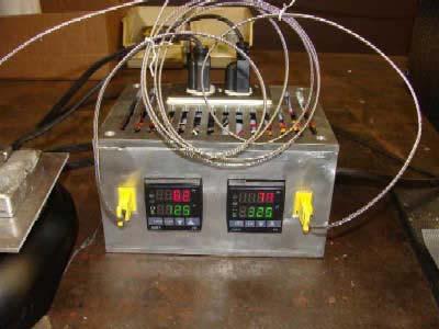
1 The Los Angeles Silhouette Club Dual PID Temperature Controller By: Keith G. Benedict This article reprinted with permission of Keith G. Benedict (Originally posted on Castboolits.com) As part of a long term process of developing the technology and knowledge base to make custom bullet molds it was necessary to have available a means to control and monitor the temperature of a lead melting pot and a bullet mold. I decided to build a dual temperature controller using digital PID controllers, appropriate type K thermocouples, and other components supplied by Auber Instruments Inc. A PID controller is a device that compares the set point value (what you want) to the actual process value (what you've got) from your sensor over a period of time. PID stands for Proportional-Integral-Derivative. Proportional control merely looks at the difference between set point and process values to determine whether to turn on or off an output. A simple bimetallic thermostat operates this way, but this mode of control produces overshooting/undershooting and a constant cycling of the process value above and below the set point value Derivative refers to the rate of change of the process variable over time as control action takes place. Integral control is based on the total time and magnitude of the error between the process value and the set point value. These latter two modes are designed to minimize undershoot/overshoot and improve system stabilization. These particular controllers have a discrete (on/off) output; during operation the controller cycles it on and off for certain time periods to maintain control as closely as possible. The Auber PID controllers have a number of user-friendly features that make them work well for this type of application. They accept analog input directly from a thermocouple (and other sensors), can be operated on a range of input AC voltages, and can be had with internal relay outputs or DC outputs to operate external mechanical or Solid State Relays. They also can actuate external alarms (which I am not utilizing in this application), will autotune themselves, and are small and relatively inexpensive. Parts List: 2 - PID controllers Auber #SYL-2352 $ Type K thermocouple w/6 probe Auber #WRNK-171 $ Type K thermocouple ¼ -20 probe Auber #TC-K6 $ A Solid State Relays Auber #RS1A40D25 $ Panel mount thermocouple connectors Auber #TCCON $ dual outlet 110VAC female socket $ cable clamp $ approx 48 of 1/4 x aluminum plate $ fuse holder and box of 20A Type T fuses $ tube of heat sink silicone grease $ VAC three prong male plug terminal strip - 1-6' 12 ga 3 conductor stranded rubber coated cable - 1
2 miscellaneous 14 ga hookup wire (red, yellow, black, white) - miscellaneous crimp on connectors - miscellaneous screws - bits and pieces of repurposed shop scrap - (un-priced items are items I had on hand) Total* $ *(Total does not include the $19.50 for three orders from Auber; I should have made one order and saved $13.00) Construction: I wanted to make a fairly compact unit so a 3-D CAD system was used to aid the design process. The Auber site has technical information on their products, including the dimensions of the major components. Other components that were on hand were simply measured using suitable tools. Each component was turned into a simple rectangular object and locate in space to enable the box to be built around it. The overall dimensions of the box ended up being 8" long, 4-1/2" high, and 6-1/4" deep. Once this was done it was easy to take the six box panels and locate hole centers and other relevant features. Each panel was then dimensioned and printed as an individual part to take to the machine shop. The box panels are made from 1/4 aluminum plate which was cut to size by sawing and milling. All the holes were drilled and counter bored where required using a vertical milling machine. The square holes in the front panel for the two PID controllers were milled, as were the holes for the thermocouple socket. The thermocouple sockets were designed to be mounted on gauge sheet metal so these had to be recessed into the front to allow the rear spring clip to lock them in place. The area around the cable clamp hole on the inside of the right panel was also relieved for the same reason. The hole for the 110VAC socket was also milled out. The holes were tapped using a hand tapping machine. The bottom, front, and both sides were then clamped up to maintain size and squareness and TIG welded on the inside. The corner brackets used as attachment points for the top and back panels were then welded in place. The box was then returned to the mill and the holes for the top and rear screw holes were drilled, again followed by hand tapping. The box was then assembled to give it rigidity and clamped into the mill vise, where the bottom vent slots were cut. The top was removed and clamped in the vise and the vent slots were cut. All the components were given a thorough cleaning, first in a parts-washing tank, followed by a wipe down with acetone. The terminal strip for the 110VAC connections and the fuse holder were screwed into place first, followed by the cable clamp. The 110VAC cable was then anchored into place. The black (hot) lead had a female spade lug crimped on and then it was connected to the fuse holder. The white (neutral) wire was extended to the terminal strip where it was stripped at intervals and looped around the screws on one side of the terminal strip. The green (ground) wire was connected to one of the mounting screws on the end of the 2
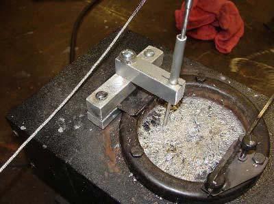
3 terminal strip, where it would ground to the case. A jumper wire with a female spade lug crimped on one end and stripped at intervals on the other end was used to connect the fuse holder to the terminal strip. The thermocouple wires were then cut off by about six inches to provide a length of wire to go from the thermocouple socket to the controller. The cut ends were stripped and bent into a loop. The thermocouple was connected to the male plug, and the short section was connected to the female socket., leaving the spade lugs unconnected for the moment. Polarity is very important here - my thermocouple wires were marked red positive and had a red thread in the wire covering. The SSRs are mounted with the power terminals on the bottom, where the terminal strip makes inserting the wire difficult, so 12 gauge black jumpers wire connected before they were mounted to the case. Heat sink grease was applied to the bottom of the SSRs before mounting. The PID controllers each had four eight inch long 14 gauge jumper wires connected black and white to the AC power terminals, red to the positive SSR coil output, yellow to the negative SSR coil output. The thermocouple sockets were inserted and anchored into place with the supplied spring clips. The PID controllers were inserted into the face and the retaining clips were put on loosely. The thermocouple wires were connected to the proper terminals on the PID controller, which was then securely anchored with the spring clip. The yellow and red wires hooked to the proper polarity terminals of the SSR, and the white and black wires connected to the 110VAC terminal strip. One of the power wires of the SSR was connected to a black (hot) terminal on the terminal strip. The other was connected to one of the brass terminals on the 110VAC socket. The 20A socket had the connector strip on the side removed so that each plug-in was controlled separately. The silver (neutral) side of the socket was not altered so only one white wire was needed to connect it to the terminal strip. No ground wire was used as the socket grounds to the box. The 110VAC socket was then mounted to the top panel and a metal cover was secured in place. A fuse was inserted into the fuse holder and the top and back panels were then mounted to the box. A three prong male plug was connected to the end of the power cable, completing the assembly. Operation: The thermocouples were plugged in and the unit was plugged into a heavy duty extension cord on a 20A branch circuit. It was thrilling when nothing exciting happened and everything powered up normally. The units were preset at 50F and the thermocouples were exposed to ambient air temperature and within a few minutes both stabilized within one degree of the same 67-68F temperature reading. With everything working normally it was time to test the unit. A simple thermocouple holder for the Lyman 20 pound bottom pour lead pot was made from shop scrap. It allows 3


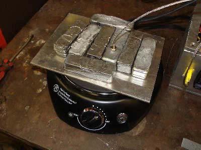
4 the thermocouple probe to be inserted into the melt to a consistent depth and can be swung out of the way for fluxing when the probe is removed. Since a bullet mold was not available for preheating, a one pound lead ingot was drilled and tapped with a 1/4-20 thread and the other thermocouple was screwed into it. A protective aluminum plate was placed over the hot plate used for preheating and eight ingots, including the instrumented one, were placed on top. The Lyman furnace and hot plate were plugged into the appropriate sockets and both units were turned all the way one, effectively cutting out the thermostats built into each unit and allowing the PID controller to cycle the power to the devices. Again nothing exciting happened. The set point value of the controllers were then entered. The lead pot was set to 725F, the hot plate to 325F. Within a minute or two the temperature reading began to increase. Within minutes the hot plate was approaching the desired temperature and the autotune function was engaged. It overshot the temperature by about 40F the first time but settled down within a few minutes and held temperature within about +/- 10F after a while. This was not unexpected, as it is a system with a powerful input to a low thermal mass with a lot of surface area exposed to air currents. Within about 20 minutes the lead pot was approaching the set point value and the autotune was engaged. It overshot by about 30F at first but stayed within +/-5F after that, with +/- 2F control most of the time. No material was added or removed from the pot at this time so how good control will be during operation is yet to be determined. It is expected that temperature swings can be minimized by preheating ingots to a consistent temperature on the hot plate. In the future I plan to attach a thermocouple to several special molds, but I do not plan to drill and tap all my molds. I think that putting a mold in the middle of a bunch of ingots held at a specific temperature on a hot plate would work just fine. The system was operated at steady-state conditions for several hours. At no time did the area of the side panels under the SSRs get warm enough to feel. No heat was felt coming through the air vents on the top. Despite the small size of the unit it runs cool. So far I am pleased with the results. Pictures Included here are various shots of the completed unit: 4


5 The Los Angeles Silhouette Club Front Page Index to all LASC Articles 5
Note: Please read through the entire guide before attempting any kind of installation.
 KIT-RSNSb Installation Guide Version 1.3 Auber Instruments, 730 Culworth Manor, Alpharetta, GA 30022 e-mail: info@auberins.com Tel: 770-569-8420 www.auberins.com This is a PID controller kit installation
Fabricating and Installing Headlight Relays. Mike Graham
 Fabricating and Installing Headlight Relays Mike Graham For some time I had been reading about the benefits of installing headlight relays. As I understand it, there are two principal benefits: the load
Start-Up, Operation and Service Instructions
 Article I. Krueger Proportional LineaHeat W/ Discharge Temperature Start-Up, Operation and Service Instructions SAFETY NOTE Air-handling equipment will provide safe and reliable service when operated within
Note: Please read through the entire guide before attempting any kind of installation.
 KIT-RSRTD Installation Guide Version 1.5 Auber Instruments, 730 Culworth Manor, Alpharetta, GA 30022 e-mail: info@auberins.com Tel: 770-569-8420 www.auberins.com This is a PID controller kit installation
Note: Please read through the entire guide before attempting any kind of installation.
 KIT-RSP Installation Guide Version 1.3 Auber Instruments, 730 Culworth Manor, Alpharetta, GA 30022 e-mail: info@auberins.com Tel: 770-569-8420 www.auberins.com This is a PID controller kit installation
PYRTE. Building The Front Axle, Fork and Steering
 PYRTE Building The Front Axle, Fork and Steering The front axle on this traction engine is a very simple affair, in that it is a rectangular steel rod, sat on edge, with a pivot in the centre, which is
BMW 2002 M42 Swap Notes-THIS IS NOT FINISHED
 BMW 2002 M42 Swap Notes-THIS IS NOT FINISHED This document is to help those that want to install an m42 into a BMW 2002. It is based around an e30 engine, trans, and wiring. You can use the e36 block/head/wiring
Change the and later A/C & Heat system on the Discovery coach With the multi-zone coleman mach thermostat
 Change the 2001.5 and later A/C & Heat system on the Discovery coach With the multi-zone coleman mach thermostat This schematic and wiring diagram is to be used only for single stage heating and single
Safe-T-element Installation Instructions
 Safe-T-element Installation Instructions For: PTI STEZA (2x2 Burner Configuration) & PTI STEZB (3x1 Burner Configuration) Revision K (May. 3 2012) TABLE OF CONTENTS 1. PREPARATION... 3 1.1 General Safety
Triumph Street Triple VSM Grip Heater Install
 Triumph Street Triple VSM Grip Heater Install Introduction: With winter fast approaching and with painful memories of last winter riding with the club it was time to do something about getting some grip
Auber Instruments v1.1 12/29/ Enclosure Disassembling all the screws and the enclosure will be spitted into four pieces:
 1. Enclosure Disassembling all the screws and the enclosure will be spitted into four pieces: Figure 1. Top and Body of Qbox1. Figure 2. Rear Plate of Qbox1. Note: please use a hand drill to enlarge the
Part Name/Description Part No. PF3000 PF 3000 Pro U-Bracket Short Bracket PF3000 Pro
 Note: Indented items indicate parts included in an assembly listed above Part Name/Description Part No. PF3000 PF 3000 Pro U-Bracket Short 2000105-2 1 PFadvantage Bracket PF3000 Pro 2000773 1 Cable Kit
Tip: LED Lighting for the 3098 Locomotive and 4392 Coach Set Date: , ,
 Hi All, Over the past few months I have been working at a steady pace to install LED lighting in my passenger coaches. The coach lighting must have LED lights to reduce power consumption on the layout
Air Compressor/Water Pump IV - Pilot Valve Stem, Test & Installation
 Page 1 of 8 Air Compressor/Water Pump Part IV Pilot Valve Stem, Test & Installation Nelson Riedel Nelson@NelsonsLocomotive.com Initial: 1/13/04 Last Revised: 0 Valve Test: I decided to test the steam valves
JConn Inv. PID Controller Instruction Manual
 JConn Inv. PID Controller Instruction Manual This information is specific to the Mypin TA4 based controller sold by JConn Inv. but it should work for most TA4 types - within limits. Table of Contents 1.
Connector Systems Inc. SS-20 MACHINE MANUAL
 Connector Systems Inc. SS-20 MACHINE MANUAL INTRODUCTION Your SS-20 machine comes to you fully equipped and set up to terminate the style of plug you have requested. Our SS-20N will accommodate those
MASTERsine Inverter PXA Series Installation Guide
 Backup Power System Expert TM MASTERsine Inverter PXA Series Installation Guide Important Safety Instructions IMPORTANT: Read and save this Installation Guide for future reference. This chapter contains
Castle Model TSM-21 Standard Screw Pocket Machine
 Castle Model TSM-21 Standard Screw Pocket Machine "For Models with Serial Number 62481 and Above" Items Included with Machine Part No. Description Qty B00964 Castle 9/64 Cobalt Drill Bit w 1/4" Shank 1
Toddler Activity Box
 SCHMIDT CONSULTING Toddler Activity Box Tom Schmidt 12/7/2016 tom@tschmidt.com http://www.tschmidt.com As a newly minted grandparent I wanted to build a toddler activity box. The box has electronic gizmos
THIS GUIDE IS INTENDED FOR DEALERS AND SOLAR COMFORT TECHNICIANS ONLY AND IS NOT MEANT OR INTENDED TO BE REPRODUCED OR DISTRIBUTED TO THE CONSUMER
 THIS GUIDE IS INTENDED FOR DEALERS AND SOLAR COMFORT TECHNICIANS ONLY AND IS NOT MEANT OR INTENDED TO BE REPRODUCED OR DISTRIBUTED TO THE CONSUMER Table of Contents Page Tools Needed (A) 3 Replacement
How to Make a Solid State Instrument Voltage Regulator
 Taken from the web page: http://chris66dad.tripod.com/id29.html How to Make a Solid State Instrument Voltage Regulator Note: Although this description was intended for a Ford Mustang, it also works for
Deluxe High Amp Switch Kit - 12 Volt Wiring Instructions
 1404 N. Marshall Ave. El Cajon C 92020 WLH 09/01/16 514-0139 OUT IN 16 ga. Black wire 16 ga. Green wire Yellow Black Blue 50 AMP BREAKER MOTOR 16 ga. White wire ROCKER SWITCH (IN CAB) BATTERY 607-0139
50 1/50 2 Directional Contactor Installation
 50 1/50 2 Directional Contactor Installation Thank you for purchasing our 5091 or 5092 Directional Contactor. We take great pride in our products and feel certain that this Contactor will offer you many
RapidLED Oceanic BioCube 8 Retrofit Contents
 RapidLED Oceanic BioCube 8 Retrofit Contents Foreword... 2 Outline... 2 Hood Preparation... 2 Attaching LEDs to Heatsink and Wiring LEDs Together... 6 Thermal Grease... 6 Soldering Notes... 7 Tinning Wire
HPP1 MK6-15A/20A R00 Owners Manual
 J Wolmarans Page 1 2018/10/23 Page 1 of 7 TABLE OF CONTENTS Page 1 Introduction...2 2 Model...2 3 Safety warnings...2 4 Contents...2 5 Features...2 6 Installation...3 6.1 Mounting the unit:...3 6.2 Connecting
Smart Switch Basic Kit - 24 volt ( ) Wiring Instructions
 Wiring Instructions") Smart Switch Basic Kit - 4 volt (54-08) Wiring Instructions NB 8/0/ 6 ga. wire 6 ga. wire 6 ga. wire OUT IN 6 ga. wire Yellow Black Blue 50 AMP BREAKER MOTOR 6 ga. wire 6 ga. wire 6 ga. wire ROCKER SWITCH
Smart Switch Basic Kit - 4 volt (54-08) Wiring Instructions NB 8/0/ 6 ga. wire 6 ga. wire 6 ga. wire OUT IN 6 ga. wire Yellow Black Blue 50 AMP BREAKER MOTOR 6 ga. wire 6 ga. wire 6 ga. wire ROCKER SWITCH
Installation Guide. Installation Guide. Exploded Views Installation Instructions Mounting System Parts List. USTarp.
 Installation Guide Installation Guide Exploded Views Installation Instructions Mounting System Parts List USTarp.com 800-249-0297 Fits dump trailers up to 40 long, or up to 45 long with Bulletproof HD
POWER SUPPLY MODEL XP-800. TWO AC VARIABLE VOLTAGES; 0-120V and 7A, PLUS UP TO 10A. Instruction Manual. Elenco Electronics, Inc.
 POWER SUPPLY MODEL XP-800 TWO AC VARIABLE VOLTAGES; 0-120V and 0-40V @ 7A, PLUS 0-28VDC @ UP TO 10A Instruction Manual Elenco Electronics, Inc. Copyright 1991 Elenco Electronics, Inc. Revised 2002 REV-I
Using your Digital Multimeter
 Using your Digital Multimeter The multimeter is a precision instrument and must be used correctly. The rotary switch should not be turned unnecessarily. To measure Volts, Milliamps or resistance, the black
How to Replace a Switch
 How to Replace a Switch The switches are the ones most frequently replaced, either because a switch has failed or because you want to substitute a newer type. Before deciding that a switch has failed,
TIP SHEET. Installation Tips for your RS OL-MDB-CH6 (1) (for Jeep vehicles) T1227 v1.0 3/19/14
 (for Jeep vehicles) T1227 v1.0 3/19/14") TIP SHEET Installation Tips for your RS-360 + OL-MDB-CH6 (1) (for Jeep vehicles) T1227 v1.0 3/19/14 Thank you for purchasing your remote start from MyPushcart.com - an industry leader in providing remote
TIP SHEET Installation Tips for your RS-360 + OL-MDB-CH6 (1) (for Jeep vehicles) T1227 v1.0 3/19/14 Thank you for purchasing your remote start from MyPushcart.com - an industry leader in providing remote
ELECTRICAL SYSTEM UPGRADE
 NEW CONTROLLER & ELECTRICAL SYSTEM UPGRADE FOR DAIRY TECH, INCORPORATED 10, 30 & 60G PASTEURIZERS Parts to Include 2 Wire ties (Nuts) 2 sticky wire mount pads Large Rubber Grommet (for bottom of electric
INSTALLATION INSTRUCTIONS
 INSTALLATION INSTRUCTIONS FUEL PUMP SLEEVE INSTALLATION KIT 2001-2006 BMW E46 M3 Document# 19-0058 Customer Support: info@radiumauto.com 1. There are 2 common ways to relieve fuel pressure on the BMW.
INSTALLATION INSTRUCTIONS HIGH OUTPUT 2 SPEED RAD FAN ASSEMBLY
 INSTALLATION INSTRUCTIONS HIGH OUTPUT 2 SPD RAD FAN ASSMBLY PART # 66818, 66819, 66820, 66821, 66822, 66823, 66827 & 66828 Please read these instructions completely before beginning installation FAN SHROUD
Temperature Controlled Soldering Station
 Instructions for 951SXe LONER Temperature Controlled Soldering Station Product Features Our newest soldering system featuring a portable compact, lightweight design with analog display Accurate linear
circuit protection & wiring accessories
 circuit protection & wiring accessories J J1 circuit breakers Circuit breakers and fuses are a cost-effective solution to protecting wiring, equipment and subsystems. While fuses are a one-time, disposable
REFRIGERATION PARTS SOLUTION
 REFRIGERATION PARTS SOLUTION Do It Yourself Kit Assembly and Installation Manual Full Gauge Digital Thermostat Retrofit Kit Digital Thermostat Upgrade for Danfoss BD Series of DC Compressor Systems with
AUXILIARY BATTERY BOX INSTALLATION INSTRUCTIONS
 AUXILIARY BATTERY BOX INSTALLATION INSTRUCTIONS The original TOMMY GATE hydraulic lift Assembling the Auxiliary Battery Box 1. Remove the cover from the auxiliary battery box by removing the two nuts and
Installation Instructions
 Installation Instructions For PTI STEZA C (2x2 Burner Configuration) & PTI STEZB C (3x1 Burner Configuration) Revision E Safe-T-Element Installation Instructions Table of Contents 1. PREPARATION..3 1.1
Step 1 Wiring your remote start. Installation Tips for your Remote Start system (for GM vehicles) V3.3 revised 9/12/2013
 V3.3 revised 9/12/2013") Installation Tips for your Remote Start system (for GM vehicles) V3.3 revised 9/12/2013 Thank you for purchasing your remote start from MyPushcart.com - an industry leader in providing remote starts to
Installation Tips for your Remote Start system (for GM vehicles) V3.3 revised 9/12/2013 Thank you for purchasing your remote start from MyPushcart.com - an industry leader in providing remote starts to
2005+ Mustang Trunk Lid Release and Trunk Lights Installation
 There is no warranty expressed or implied by this document, you follow these instructions at your own risk. These instructions worked for me, but your experience may vary. The final product of these instructions
HOW TO FIT A KEYLESS ENTRY SYSTEM
 HOW TO FIT A KEYLESS ENTRY SYSTEM THE KITS ARE WIDELY AVAILABLE TO BUY FROM THE INTERNET AND OTHER GOOD STOCKISTS HERE IS AN IDEA OF WHAT YOU SHOULD RECIEVE IN YOUR KIT. PLUS WIRING DIAGRAM PLUS WIRING
Installing the Audiovox CCS-100 Cruise Control.
 Installing the Audiovox CCS-100 Cruise Control. This article was written by: Lon Lawrence w650kawasaki@leaco.net Cruise Control : Audiovox CCS-100 ($89) Webpage : www.summitracing.com Message: I've installed
Installation Tips for your Remote Start w/ Keyless Entry (Toyota Vehicles) v3.2 Updated 3/14/13
 v3.2 Updated 3/14/13") Installation Tips for your Remote Start w/ Keyless Entry (Toyota Vehicles) v3.2 Updated 3/14/13 Thank you for purchasing your remote start from MyPushcart.com an industry leader in providing remote starts
Installation Tips for your Remote Start w/ Keyless Entry (Toyota Vehicles) v3.2 Updated 3/14/13 Thank you for purchasing your remote start from MyPushcart.com an industry leader in providing remote starts
2-row and All-row systems included.
 Ag Leader Technology Cotton Picker Installation Installation Instructions for John Deere cotton picker models: 2-row and All-row systems included. IMPORTANT: Ensure the model numbers shown above correspond
LGT-306L / LB Club Car Precedent LED Light Bar Bumper Kit Installation Instructions
 LGT-306L / LB Club Car Precedent LED Light Bar Bumper Kit Installation Instructions Caution: Please read through the instructions carefully. Before starting this project, remove the system s positive and
20 Rigid Industries LED Light Bar Installation into a 2002 Ford Super Duty
 20 Rigid Industries LED Light Bar Installation into a 2002 Ford Super Duty This write-up is how I installed the Rigid Industries 20" E-Series LED Light Bar into the grill area behind the license plate
ALTERNATOR PRECAUTIONS. Some precautions should be taken when working on this, or any other, AC charging system.
 The alternator charging system is a negative (-) ground system which consists of an alternator, a regulator, a charge indicator, a storage battery and wiring connecting the components, and fuse link wire.
Page 3. Misc. insulator pads to go under the inverter and spark box. I used the packing material from around a glass jar
 Page 1 Convert vehicle 1978 Chevy Camaro with stock 350 engine, automatic trans. Stock 4-barrel carb, and stock fuel pump. The gas tank has been changed to a metal water tank and the fill cap is vented
Servicing a Katadyn PUR40E
 Servicing a Katadyn PUR40E ABOUT THE ASSOCIATION OF OCEAN ROWERS The Association of Ocean Rowers is open to anyone interested in the sport of Ocean Rowing. It is strictly independent of all other bodies
INSTALLATION INSTRUCTIONS
 INSTALLATION INSTRUCTIONS FUEL SURGE TANK INSTALLATION KIT 1999-2006 BMW E46 COUPE Document# 19-0056 Support: info@radiumauto.com Note: This kit wasn t designed for a FST-R, but can be accomplished. 1.
Installation Tips for your Crimestopper/ProStart Remote Start system (add-on for GM vehicles) v1.02 updated 1/16/2013
 v1.02 updated 1/16/2013") Installation Tips for your Crimestopper/ProStart Remote Start system (add-on for GM vehicles) v1.02 updated 1/16/2013 Thank you for purchasing your remote start from MyPushcart.com - an industry leader
Installation Tips for your Crimestopper/ProStart Remote Start system (add-on for GM vehicles) v1.02 updated 1/16/2013 Thank you for purchasing your remote start from MyPushcart.com - an industry leader
Installation Instructions for the Plug & Play Chrysler/Dodge/Jeep Remote Start Package w/mux T5
 v1.01 12/14/2102 Installation Instructions for the Plug & Play Chrysler/Dodge/Jeep Remote Start Package w/mux T5 Review the remote start installation manual for safety instructions! Overview Your kit consists
Connecting the rear fog light on the A4 Jetta, while keeping the 5 Light Mod
 Connecting the rear fog light on the A4 Jetta, while keeping the 5 Light Mod DISCLAIMER: I'm human and make mistakes. If you spot one in this how to, tell me and I'll fix it This was done on my 99.5 Jetta.
ELECTRIC BENDING IRON
 ELECTRIC BENDING IRON This is intended as a short pictorial essay on the construction of an electrical side bending iron. As the items used may vary from the ones shown here, only limited dimensions are
Ag Leader Technology. Combine Installation New Holland TC 57, 59. Monitor Installation
 Monitor Installation Figure 1. Monitor installed on right side cab window using window mount bracket. 1. If you are in very humid conditions where moisture may condense on the glass where you are mounting
Installation Tips for your Crimestopper/ProStart Remote Start system (for GM vehicles) v1.01 updated 2/27/2012
 v1.01 updated 2/27/2012") Installation Tips for your Crimestopper/ProStart Remote Start system (for GM vehicles) v1.01 updated 2/27/2012 Thank you for purchasing your remote start from MyPushcart.com - an industry leader in providing
Installation Tips for your Crimestopper/ProStart Remote Start system (for GM vehicles) v1.01 updated 2/27/2012 Thank you for purchasing your remote start from MyPushcart.com - an industry leader in providing
INSTALLATION INSTRUCTIONS
 INSTALLATION INSTRUCTIONS FUEL SURGE TANK INSTALLATION KIT 1999-2006 BMW E46 COUPE Document# 19-0056 Support: info@radiumauto.com Note: This kit was designed for a standard single pump Radium Engineering
 CENTRIFLOW METER and ELECTRONICS WIRING and INSTALLATION MANUAL REV 01/16 ORIGINAL LANGUAGE Copyright 2016 Eastern Instrument Laboratories, Inc. All Rights Reserved. TABLE OF CONTENTS SAFETY Safe Operation...
Installation Tips Crimestopper/ProStart Remote Start system + PLJX + DLRM + SPDT (for GM vehicles) T0760 v1.1 updated 2/5/14
 T0760 v1.1 updated 2/5/14") Installation Tips Crimestopper/ProStart Remote Start system + PLJX + DLRM + SPDT (for GM vehicles) T0760 v1.1 updated 2/5/14 Thank you for purchasing your remote start from MyPushcart.com - an industry
Installation Tips Crimestopper/ProStart Remote Start system + PLJX + DLRM + SPDT (for GM vehicles) T0760 v1.1 updated 2/5/14 Thank you for purchasing your remote start from MyPushcart.com - an industry
ECT Display Driver Installation for AP2 Module
 ECT Display Driver Installation for AP2 Module Overview The ECT Display Driver is a small module with a removable wire harness that mounts behind the driver's foot well cover. All wiring connections are
715B CONTROL SERIES. Instruction Manual Line Voltage DC Brushless Motor Control CONTROLS. Phone (317) Fax (317)
 Fax (317)") 715B CONTROL SERIES CONTROLS Instruction Manual Line Voltage DC Brushless Motor Control LT715B (IM-715B-0100) P.O. Box 10 5000 W. 106th Street Zionsville, Indiana 46077 Phone (317) 873-5211 Fax (317) 873-1105
715B CONTROL SERIES CONTROLS Instruction Manual Line Voltage DC Brushless Motor Control LT715B (IM-715B-0100) P.O. Box 10 5000 W. 106th Street Zionsville, Indiana 46077 Phone (317) 873-5211 Fax (317) 873-1105
INSTALLATION INSTRUCTIONS
 INSTALLATION INSTRUCTIONS Accessory REAR SPOILER Application 2011 CR-Z MUGEN Publications No. AII 45919 Issue Date APRIL 2011 PARTS LIST Right wing bracket Rear wing Left wing bracket Right wing base Right
OpenEV. OpenEVSE 40A Charging Station. Build a Charging station for a 50A circuit (40A Charge current) with an OpenEVSE kit.
 with an OpenEVSE kit.") OpenEV OpenEVSE 40A Charging Station Build a Charging station for a 50A circuit (40A Charge current) with an OpenEVSE kit. Written By: Christopher Howell 2017 openevse.dozuki.com/ Page 1 of 13 INTRODUCTION
OpenEV OpenEVSE 40A Charging Station Build a Charging station for a 50A circuit (40A Charge current) with an OpenEVSE kit. Written By: Christopher Howell 2017 openevse.dozuki.com/ Page 1 of 13 INTRODUCTION
Brake and Tail Light Kit Workman 1100/2100 and Twister Utility Vehicles
 Form No. 5-90 Brake and Tail Light Kit Workman 00/00 and Twister Utility Vehicles Part No. 0 6697 Installation Instructions Important Before installing this kit, you must have Wiring kit number 99 79 installed
CHECKLIST & COMPONENTS
 Eclipse Compact www.rollershuttercompany.com Tel 0800 6444121 55mm Roller Garage Doors CHECKLIST & COMPONENTS EQUIPMENT REQUIRED 2 x Step ladders or hop ups Spirit level Tape measure Power drill 10mm A/F
A $10 Upgrade to my Harbor Freight 90 Amp Flux Wire Welder, version 2
 A $10 Upgrade to my Harbor Freight 90 Amp Flux Wire Welder, version 2 By R. G. Sparber Copyleft protects this document. 1 My Harbor Freight 90 amp flux wire welder is surprisingly good. But as with most
Hiding a Ford Regulator in an Alternator Equipped Citroen D s and SM s By Mark L. Bardenwerper, Sr. January 3, 2007
 Hiding a Ford Regulator in an Alternator Equipped Citroen D s and SM s By Mark L. Bardenwerper, Sr. January 3, 2007 Many of us have replaced the Ducellier voltage regulators on our alternator equipped
SPACESAVER EC-300 A ELECTRICS
 INSTALLATION INSTRUCTIONS SPACESAVER EC-300 A ELECTRICS SECTION I TOP MOUNTED ELECTRICS SECTION II FACE PANEL MOUNTED ELECTRICS SECTION III ZFS INSTALLATION INSTRUCTIONS This symbol indicates a connection
11. Completing the Fuselage Engine Installation
 11. Completing the Fuselage Engine Installation Engine Installations 11 1 230399 - Fit Engine Mount Reference: Photo 11.16(a) Parts Required: 4025094 Backing Plate Engine Mount (4) AN4-20A Bolt (4) AN3-11A
Applicable to the Following Part Numbers. Notes and Maintenance. Torque Specifications. Metric SAE. Use above torque setting unless otherwise noted
 INSTALLATION MANUAL Level of Difficulty Moderate This is the second first of two of two manuals required to complete this installation. The first second manual manual is is included with with your mounting
CLASS # GAUGE ROUND POWER CORDS
 16 GAUGE ROUND POWER CORDS These 16 gauge, 3 wire orange power cords will stay flexible down to -40. They feature a heavy duty double vinyl jacket insulation and molded male and female ends. The cords
Turn Signal Kit Installation Instructions for Model A Fords & Other Antique Vehicles
 Turn Signal Kit Installation Instructions for Model A Fords & Other Antique Vehicles Lifetime Technical Support support@logolites.com 770-476-7322 www.logolites.com Manual 100-0005N Thank you for purchasing
Installation Tips for your Remote Start system (for RS4LX>GMBP for GM vehicles)
") Installation Tips for your Remote Start system (for RS4LX>GMBP for GM vehicles) Thank you for purchasing your remote start from MyPushcart.com - an industry leader in providing remote starts to doit-yourself
Installation Tips for your Remote Start system (for RS4LX>GMBP for GM vehicles) Thank you for purchasing your remote start from MyPushcart.com - an industry leader in providing remote starts to doit-yourself
Race Sport Lighting RSUKIT LED UNDERBODY KIT INSTALLATION GUIDE
 Race Sport Lighting RSUKIT LED UNDERBODY KIT INSTALLATION GUIDE PARTS LIST (INCLUDED IN THE KIT) 1 x LED Control Center Box 2 x 48 RGB Aluminum Channel LED Bars 2 x 36 RGB Aluminum Channel LED Bars 1 x
COMANCHE GEAR Regent Circle Naples, FL Phone & fax 239/ Cell 239/ Main gear doors miscellaneous
 COMANCHE GEAR 10340 Regent Circle Naples, FL 34109 Phone & fax 239/593-6944 Cell 239/404-7524 www.comanchegear.com Main gear doors miscellaneous Here are a few thoughts to consider if you are having a
3000 SERIES DRY-BLOCK HEAT SOURCE
 3000 SERIES DRY-BLOCK HEAT SOURCE USER MANUAL Please read this manual before switching the unit on IMPORTANT safety information inside TABLE OF CONTENTS 1 INTRODUCTION 1 2 SAFETY 2 3 OPERATION 3 3.1 Parts
HPP1 MK5 Owner s Manual
 J Wolmarans Page 1 2017/03/07 Page 1 of 10 TABLE OF CONTENTS Page 1 Introduction...2 2 Models...2 3 Safety warnings...3 4 Features...3 5 Contents...3 6 Installation...3 6.1 Mounting the unit:...3 6.2 Connecting
GENERAL <ELECTRICAL>
 00E-1 GROUP 00E GENERAL CONTENTS HARNESS CONNECTOR INSPECTION................................. 00E-2............. 00E-6................. 00E-6 TROUBLESHOOTING STEPS.......... 00E-6 INFORMATION
GENERAL <ELECTRICAL>
 00E-1 GROUP 00E GENERAL CONTENTS HARNESS CONNECTOR INSPECTION................... 00E-2............. 00E-6................. 00E-6 TROUBLESHOOTING STEPS.......... 00E-6 INFORMATION FOR DIAGNOSIS.......
Ford Super Duty F-250, F and up
 Ford Super Duty F-250, F-350 2005 and up Installing Upfitter Switches by Richard L. Ray If you want to add a few aftermarket options to your new Ford Super Duty, Ford Motor Company makes things easy for
Air Compressor/Water Pump III - Making the Steam Valves
 Page 1 of 14 Air Compressor/Water Pump Part III Making the Steam Valves Nelson Riedel Nelson@NelsonsLocomotive.com Initial: 1/09/04 Last Revised: 0 The cylinders pistons and water valves were completed
Installation and Construction Notes for EVSE4
 Installation and Construction Notes for EVSE4 You need to read and understand this if you want to build an EVSE that will be safe and need to pass a building inspectors review. Before beginning this process
Peugeot 406 Coupe: Delocking your boot V.1 April 2005
 This is a first stab at a DIY guide to de-locking your 406 Coupe. It isn t a hard modification to do yourself, but you do need to be confident working on your cars electrics and removing and refitting
Consult electrical engineer before use. cal enterprises ltd. Instructions for use
 Washing Machine Motor Speed Controller Consult electrical engineer before use. cal enterprises ltd Instructions for use Contents Page 2 Disclaimer Page 3 Introduction Page 4-6 Bits to salvage Page 7-8
INSTALLATION INSTRUCTIONS
 INSTALLATION INSTRUCTIONS Universal Air Series!! NOTE!! Covers the following model: 6000 Series 85-0100B-AZ Rev 0 5/07 To ensure that the system is installed properly, provide your electrician with these
CM 5000D IN A HURRY?
 CM 5000D Conventional and Tunnel Instructions IN A HURRY? Flip to Pages 6-13 for Wiring Diagrams 4-11. Investigate The REEL-FREE Winch Handle The REEL-FREE Winch Handle adds features to your curtain winching
PARTS LIST FOR LN-25 LN-25
 P-374 P-374 PARTS LIST FOR 200 250 300 350 400 450 500 550 600 650 700 100 150 50 IN IN/MIN WIRE FEED MORE T13086-99 1. 5. 4. 3. 2. IN/MIN. USED. cross. 35 31 23 25 27 29 15 17 19 21 P-374-A P-374-A ILLUSTRATION
The Quality of Light TM. MODEL: SSI-600-PDC Controller Operation Manual. Metaphase Technologies Inc. JAN-09
 The Quality of Light TM MODEL: SSI-600-PDC Controller Operation Manual For packaging purposes the line light and controller are shipped separately. The user must make the connection currently according
MOTOALLIANCE WINCH MOUNT
 , / 1-866-527-7637 www.motoalliance.com MOTOALLIANCE WINCH MOUNT Polaris RZR Thank you for purchasing our MotoAlliance winch mount(s). You now own a premium custom winch mount to allow you to use your
Kodak 750H Carousel Projector Repair
 Kodak 750H Carousel Projector Repair An AT YOUR OWN RISK PROJECT by Klaus Wolter, Rev B, 3-26-2016 Here I documen the repair of my 750H carousel. A common problem with this projector, and all of the projectors
MODEL 540 USER MANUAL INCORPORATING MODEL 530 TEMPERATURE CONTROLLER
 MODEL 540 USER MANUAL INCORPORATING MODEL 530 TEMPERATURE CONTROLLER Signal Group Limited 12 Doman Road, Camberley Surrey, GU15 3DF England Tel: +44 (0) 1276 682841 Fax: +44 (0) 1276 691302 e-mail: instruments@signal-group.com
TECH TIPS. Ford LRG423. Service Call: Unit will not stay running on gas from Platform Controls but runs fine on propane.
 Service Call: Unit will not stay running on gas from Platform Controls but runs fine on propane. Tools Needed: 7/16 wrench 1 relay multimeter 12" blue wire side cutters 12" red wire wire stripper 20" black
OPERATOR S MANUAL StudPro LiteXI Pin Welder Stud Welding Products, Inc
 OPERATOR S MANUAL StudPro LiteXI Pin Welder CONTENTS Description Pages Safety 2 Specifications and Features 3 Product Components 4-5 Screen Operation 6-8 Setup and Welding 9-11 CD Gun Exploded View 12
POWERED RUNNING BOARDS INSTALLATION MANUAL
 POWE RUNNING BOARDS INSTALLATION MANUAL Level of Difficulty Moderate Parts List 1 Driver / left running board* 1 Passenger / right running board* 4 Mounting bracket, standard 2 Mounting bracket, middle
GVW AGM Auxiliary Battery Kit for Vanagon Westfalia Full Camper
 GVW-253-700AGM Auxiliary Battery Kit for 1983-1991 Vanagon Westfalia Full Camper The purpose of this kit is to add an Interstate SLA1161 as an auxiliary battery under the driver's seat of 1983 to 1991
USER MANUAL FOR 2000 WATTS POWER INVERTER USER S MANUAL--Read before operating this equipment
 USER MANUAL FOR 2000 WATTS POWER INVERTER Your 2000 watts power inverter converts 12-volt vehicle battery power into 230 volts of AC power. You can use the inverter in your vehicle to operate many types
SERVICE MANUAL (INTERNATIONAL)
") SERVICE MANUAL (INTERNATIONAL) IMPINGER CONVEYOR OVENS MODEL 1421-000-E, 1454, 1455 WITH PUSH BUTTON CONTROLS Lincoln Foodservice Products, LLC 1111 North Hadley Road Fort Wayne, Indiana 46804 United States
SERVICE MANUAL (INTERNATIONAL) IMPINGER CONVEYOR OVENS MODEL 1421-000-E, 1454, 1455 WITH PUSH BUTTON CONTROLS Lincoln Foodservice Products, LLC 1111 North Hadley Road Fort Wayne, Indiana 46804 United States
1 Product Description System Layout Safety Instructions Intended Use Installation... 3
 Order Number 0812xx- Contents 1 Product Description... 2 2 System Layout... 2 3 Safety Instructions... 3 4 Intended Use... 3 5 Installation... 3 5.1 Hanger Clamp... 3 5.2 Cutting of Conductor Rail... 4
SL15/20-6 AND SL15/20-10 INSTALLATION INSTRUCTIONS
 STOWAWAY SideLoader Tailgates By THIEMAN SL15/20-6 AND SL15/20-10 INSTALLATION INSTRUCTIONS! IMPORTANT! KEEP IN VEHICLE! READ AND UNDERSTAND THE CONTENTS OF THIS MANUAL BEFORE OPERATING THE EQUIPMENT.