Note: Please read through the entire guide before attempting any kind of installation.
|
|
|
- Myrtle James
- 6 years ago
- Views:
Transcription


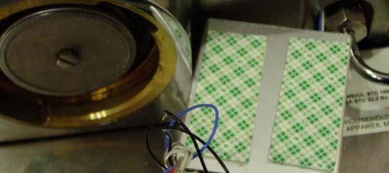
1 KIT-RSP Installation Guide Version 1.3 Auber Instruments, 730 Culworth Manor, Alpharetta, GA Tel: This is a PID controller kit installation guide solely distributed to our clients, who have purchased the KIT-RS kit. Once you are done with this guide, please send us your feedback, comments, and/or suggestions (via to auberins@gmail.com) so that we may continue making improvements on this guide. Your help is greatly appreciated! Note: Please read through the entire guide before attempting any kind of installation. Disclaimer: This product was created and distributed by Auber Instruments Inc. Everything included in this guide (images, text, etc.) is the intellectual property of Auber Instruments Inc. Thus, this guide is not to be replicated, altered, or sold without express written permission from Auber Instruments Inc. If you did not receive this document from Auber Instruments Inc, please let us know; as it is subject to inaccuracy and/or obsolescence. The Rancilio Silvia names and trademarks are owned by Rancilio Macchine per caffè. S.p.A. The modifications of Rancilio Silvia involve tampering with high-wattage electrical circuits in a wet environment, which could result in electric shock, burns, other serious personal injury or death, as well as fire, explosion and other property damage. This kit is for users with proper electrical safety knowledge only. Attempting to access your espresso machine will void its warrantee. You, the user, will assume full responsibility for any modifications undertaken. Auber Instruments Inc is not liable for any damage caused to your property as a result of improper use. Parts Identification. Fig 1. PID Controller, Aluminum extrusion box, rubber grommet, double sided tape pre-assembled - Front view on left. Back view on right. 1
, mounting screw nut and")
 for SSR and sensor, and")


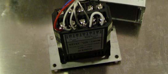
2 Figure 2. Solid State Relay (SSR), mounting screw nut and washer for SSR, silicone heat transfer compound (white paste in the vial) for SSR and sensor, and RTD jumper cable (see D 3)). Figure 3, Cables for connecting SSR output to heater. Terminated with spade tongue terminal on one end and tab terminal on the on other end. Figure 4, Cables for connecting controller output to SSR input. Red colored cable for positive. White colored cable for negative. Terminated with spade tongue terminal on one end. 2


3 Figure 5. Cables for tapping power to controller. One black and one brown color, terminated with piggyback connector on one end. Figure 6, The RTD temperature sensor.. Figure 7, Cable ties Fig 8a. Steam control cable 3

 Disconnect the power cord from power outlet.")
 Remove the splash guard panel.")
4 Fig 8b, Upper, brew pump control cable. Lower, jumper cable for brew pump control Fig 8c. Controller box ground wire. Procedure A. Preparation for installation. 1) Disconnect the power cord from power outlet. Remove the water tank, portafilter, and drip tray. 2) Remove the splash guard panel. Remove the screws indicated by the red arrows in Fig 9. Slide the stainless panel out from left side. Figure 9. Red arrows indicates the screws that hold the splash guard panel. 4

 Remove the back panel of the machine. Remove the two screws indicated in Fig 12a.")
5 3) Remove the top cover. Remove the screws indicated by the red arrows in Fig 10. Pull out the top panel. Figure 10. Top panel. Red arrows indicate the screws that hold the top panel. B. Install the steam control cable. The steam control cables need to be installed on the steam switch in the location indicated by figure 11. To access the switch terminals in the lower left position, the front panel that holds the switch needs to be detached from the black colored main frame. It will take several steps to be done. Figure 11. Location of the cables to be replaced on the steam switch. 1) Remove the back panel of the machine. Remove the two screws indicated in Fig 12a. Loosen the screw indicated in Fig 12b by several turns (do not remove it). The back panel can be removed by sliding it back and lifting up. 5
.")


6 Fig 12a, Red arrow indicates the screw that hold back panel. Fig 12b. The screw on the bottom of machine that holds the back panel (Red arrow). 2) Remove the protecting panel for the pump. Remove the two screws indicated in Fig 13 and remove the panel. Fig 13. Screws that hold the protecting penal for the pump. 3) Remove the steam control valve nub. The nub is removed by pulling with a little force. It is connected by a spring clipper. The left picture of Fig 14 shows the steam valve with nub on. The right picture shows the steam valve after the nub has been pulled out. 6


. Slide the front panel out by ~5 mm (0.")


7 Fig 14. The steam valve control nub. 4) Remove the front panel. Remove the four screws shown on the top picture of Fig 15. The screws are accessible through the small hole on the U shaped frame. Loosen the two screws on the lower picture of Fig 15 (Do not remove them). Slide the front panel out by ~5 mm (0.2 ) and lift up. The front panel is now detached from the main frame. The steam switch is accessed by pulling the panel out slightly. Fig 15. Top, Location of the four screws that hold the front panel. Lower, the location of two screws in the bottom of the front panel which need to be loosened before the panel can be slide out. 7

8 5) Replace the steam control cable. The top picture of Fig 16 shows the two cables on the steam switch that need to be replaced with the new steam control cable provided. One is red and other is gray. You might need a long nose pliers to remove the connector from switch if it is difficult to reach or remove. The bottom picture shows the new cable that has been installed. The new white cable is on the top of the switch. The blue cable is piggybacked with the original red cable on the lower side of the switch. We installed it on the bottom blade of the switch because there is more space for the piggyback connector. The connector that holds the gray cables can be left hanging because this cable will be not connected to power after installation. 8

 Install the controller box ground wire to")

.")


9 Fig 16. Replace the steam control cable. The blue cable is piggybacked with the red cable that was on the switch. 6) Install the controller box ground wire to the boiler. There are two green colored ground wires installed on the boiler. Remove one of the wires (the one stick away from the boiler is proffered). Slide the piggyback connector of the controller box ground wire to the ground tap. The tab on the piggyback connector should be at the bottom. Then, install the removed ground wire to the piggyback connector as shown in Fig 16a. Fig 16a. Install the controller box ground wire to the boiler. Red arrow shows its position. 9
 Assemble the cables on SSR as illustrated in Fig 17.")

.")


10 7) Reinstall the front panel, steam valve control nub, protecting panel for pump and the back panel to its original position. C. Install the SSR 1) Assemble the cables on SSR as illustrated in Fig 17. The two red colored thick cables with soft silicone rubber insulation should be connected to the terminal marked as 1 and 2. It doesn't matter which of the two thick red cables goes to 1 or 2. The red colored the thin cable should be connected to 3 (+). The white colored thin cable should be connected to 4 (-). The clear plastic protection cover on the SSR can be removed for easy installation of the cable. Tighten the screw. Make sure the cables hold secure. Figure 17. SSR wiring. 2) The SSR is mounted on the wall behind the splash guard panel (lower right corner as shown in fig. 18). Apply small amount of the silicone heat transfer compound to the bottom metal surface of the SSR. Mount the SSR to the screw post as shown. Use the M4 screw nut and washer supplied in the kit to hold the SSR. The M4 screw can be tighten with a 7 mm socket wrench. Use a cable tie to hold four cables in place. Figure 18. SSR installed. 10
 to the outside through the space around the steam wand (Fig 24 below) C. Installation in boiler compartment Fig 19, top view of original wiring.")
11 3) Install the splash guard panel back to its original position (figure 8 above). Feed the two SSR output cables into the boiler compartment. Feed the SSR input cables (the thin red and white ones) to the outside through the space around the steam wand (Fig 24 below) C. Installation in boiler compartment Fig 19, top view of original wiring. Red arrows indicating where the controller power cable will be tapped. Green arrow points to brew water control thermostat. Blue arrow points to steam temperature control thermostat. Yellow arrow points to the screw that RTD sensor will be mounted. Pink arrow points to the white cable that will connect to brew pump control cable. 1) There are two thermostats on top of the boiler. The one on left with a red dot on top is the brewing water temperature control thermostat. The one on the right is for controlling the steaming temperature. You need to remove the cable connectors marked with green and blue arrow from these two thermostats. They need to be connected to the output cables of SSR (the two thick red wires). The green arrows in Fig 20 show what it should look like at this step. 11


.")

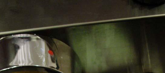
12 Fig 20. Connecting SSR output to heater (green arrows). 2) Install the washer RTD to the screw take hold the steam thermostat. Sometimes, it is convenient to work on the screws by temporarily removing the cable connector on the right side terminal of the heater. Please note that if the machine is old and as a result, the plastic protection guard of the heater connector is brittle, it might break off and leave some unprotected spots. You need to use a small to medium sized flat head screw driver to remove the screw. Be very careful to not let it drop into the gap below. If it drops to the top of the grouphead, it could be a lot of trouble to take it out. A magnetized screw driver will help. Fig 21 shows the RTD has been installed (marked with red arrow). The position of the RTD sensor will affect the performance of the controller. Please make sure the sensor is placed in the same position as the picture shows (underneath the thermostat holding bracket, not touching the cold water inlet). The round section of the sensor should touch the boiler surface. If not, you should flip it over. Do not bend the sensor tip with excess force. There is a ceramic sensor element inside the round section that is fragile. Apply small amount of silicone heat transfer compound to the gap between the sensor body and the boiler. 12

.")

13 Fig 21, RTD sensor mounting (Red arrow). 3) Tapping the controller power line to the espresso machine. The power for the controller is tapped from the main power switch by using the piggyback connectors on the black cables. Remove the connectors with black and red cable on the main power switch (red arrows on Fig 19). Remember the original position: the connector with black cable should be on the left and connector with red cable in the center). Slide the two controller power cable piggyback connectors on to the switch as shown in Fig 22a. The tab on the piggyback connector should be on the top. You need to bend it downward a little bit if the angle is too high. It is very important that black cable is put on the left side of the switch and brown cable on right. After installing the connectors, connect the cables that were just removed to the tab on the piggyback connector. It is very important to keep the original position, black on the left and red in the center (Fig. 22b). Fig 22a. The controller power cable piggyback connector location. (red arrows). Brown cable on the right and black cable on the left. 13
 Install brew pump control cable.")


14 Figure 22b. Put the original power cables back. 4) Install brew pump control cable. Remove the white colored cable from brew switch. Connect the green colored brew pump control cable to the white cable and hold it in stable place by tying it up to the blue cable. Fig 23. Fig. 23. Red arrow shows where the white cable has been removed. Green arrow shows the cable is connected to the green colored pump control cable. They are hold to a stable place by a cable tie. D. Connecting the controller. 1) Remove all 8 screws on the controller box. Save them in a safe place. 2) Fit the steam control cables, controller power cables and RTD sensor cables to the outside through the gap around the steam wand (red arrow in Fig. 24). Collect the SSR 14

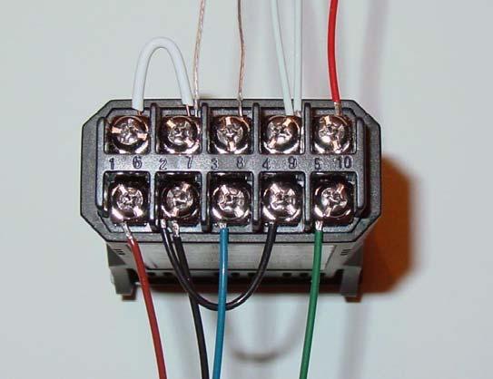
15 control cables from the back of the splash guard pane. Fit all cables through the rubber grommet on the back panel of the controller box. Make sure the direction of the back panel is as shown in figure 24. The surface with chamfered screw whole is the outside surface. Cables should come from the outside surface to the inside. You need to fit the cables through the grommet one at a time. There are nine cables total. Figure 24, Cables going through the back panel of the controller box. 3) Feed the cables through the controller box. Connect them to the controller as shown in Fig 25. Wiring the controller correctly is very critical step. Failure to install it correctly can cause damage to the machine and electric shock. The terminal numbers are printed on labels located on both sides of the controller. The brown colored power cable needs to be connected to terminal 1. The black colored power cable needs to be connected to terminal 2. Connect the brew pump control jumper cable between terminal 2 and 4. The green colored brew pump control cable needs to be connected to terminal 5, The SSR input cable has a polarity. The red colored cable from SSR is for terminal 10. Both white colored cables, one for SSR input and one for steam control are connected terminal 9. The blue colored steam control cable connects to terminal 3. The clear RTD cables need to be connected to terminal 7 and 8. The white colored RTD jumper cable needs to connect to terminal 6 and 7. Bending the wire tip will make the insertion of the cable easier as shown in Fig 26. In order to prevent the cables from coming loose when pulling on them during box installation, make sure all cables are securely tightened by a screw driver. Also, make sure there are no small wires touching the other terminals, causing a short circuit. 15
16 Fig 25a, Connecting the wire to controller. Figure 25b, Detailed view. 16
.")
 Install the controller to the box. Screw the front panel first. Make sure the surface of the box with double sided tape is on top of the controller.")
17 Figure 26. Bend the wire for easier to insert. 4) Install a cable tie as strain relief Place a cable tie at 1.5 to 2 inch away from the back of the controller (make sure the tie is not too close to the back terminals. Otherwise, the cable will have no room to bend). Cut off the tail of the tie as shown in Fig. 27. This tie will function as strain relief to preventing the wire being pulled off the terminal.. Figure 27, Install a cable tie as strain relief. 5) Install the controller to the box. Screw the front panel first. Make sure the surface of the box with double sided tape is on top of the controller. Then, gently pull out the cable from the back panel of the box until it is stopped by strain relief. Screw on the back panel. Make sure the rubber grommet is on the lower right corner (viewing from back). Mount the controller box ground wire to the lower right screw as shown in Fig
 Clean the controller box mounting area on the espresso machine with cotton ball soaked with alcohol to ensure a good adhesion")


18 Figure 28. back view of the controller box. 6) Clean the controller box mounting area on the espresso machine with cotton ball soaked with alcohol to ensure a good adhesion of the box. Fig 20. This is very important because the metal surface might contain oil that reduces the bonding strength of the tape. When properly installed, 3M double tape is very strong and durable. It has been used for industrial use such as in building structures and automobile parts. Figure 29. cleaning the box mounting area with alcohol. 7) Remove the protection film on the double side tape on the box. Slowly and carefully mount it on the espresso machine. Make sure there is a gap between the group head and box as shown on Fig. 30. It is for reducing the heat transfer to the controller. The front 18


 Tie up the wire in the boiler compartment (Fig.31).")


19 panel of the controller box should be flush with the machine front panel for make is looks neat. You have only one chance to put it in the right position. If you remove it and try to put back again, the bonding will not be as good. Figure 30. Control box position. 8) Tie up the wire in the boiler compartment (Fig.31). Make sure there are no cables touching the boiler surface. This is especially important for the cables installed by the factory. The cable installed by factory has PVC insulation that will melt when touching the hot boiler surface. It can result in electric shock. Figure 31. Tie up the cables. 19


20 9) Install the top cover. Before doing that, you should cut the excess tail of the cable tie. Check all connections that have be changed. Make sure that there are no exposed wires or connectors that will touch the top cover metal when it is installed. Some of the cables that stayed above the top cover sitting level will move when the cover is installed. If that cable has an exposed metal connector, it could result in an electric short. 10) Install the water tank. The project is done. This is how the machine should look like now. To use the machine, please read Operation manual for Rancilio Kit. 20

21 Appendix 1) Circuit diagram of Silvia. 21
 The controller OUT LED (on the left front of the controller), the LED on the SSR (on the black plastic cover), and the espresso boiler resistance")
22 2) Circuit diagram of Silvia with the KIT-RSNST connection 3) Trouble shooing procedure for not heating or not heating properly. a) The controller OUT LED (on the left front of the controller), the LED on the SSR (on the black plastic cover), and the espresso boiler resistance light (the neon lamp by the 22
23 main power switch) should be synchronized. When they are on, the heater should heat. When they are off, the heater should not heat. Note, for kit with steam control (and pre-infusion), the OUT LED will not lit in the steam mode. However, the LED on the SSR and the neon lamp on the espresso should be on when temperature is below 140C (284F) and off above that temperature. b) If all three lights lit up but no heat. There are two possibilities a) the thermal protection thermostat was triggered. The most common cause is that the temperature sensor s round section didn t touch the boiler surface. It slows down the temperature response, causing the boiler to overheat. This could happen for the kit with steam control. In addition, if you change the setting or offset of the controller without adjust the steam temperature, the boiler can get overheat to trigger the thermostat. The thermal protection thermostat is mounted on the sidewall of the boiler with a red button on the top. You can reset the thermostat by press the red button until you feel a click. b) the heater is broken. To verify if the heater is broken, you can use a multimeter to measure the resistance when the machine is off and unplugged. A working heater should have about 12 ohm resistance (48 ohm for 220V model). c) If the OUT LED of controller lit but SSR LED and espresso boiler resistance light are off, the problem is between the controller and SSR. Use a multimeter to measure the voltage between A1 and A2 of the SSR. There should be a 7-8 VDC across it. If there is no voltage, try to measure the voltage at controller between terminal 9 and 10. If there is still no voltage, the controller is bad, Otherwise, the wiring is the problem. If there is a 7-8 VDC between A1 and A2 of the SSR, most likely, the wiring polarity is wrong, A1 should be positive. If there is voltage and polarity is right, the SSR is bad. d) If the OUT LED of controller and SSR LED lit, but espresso boiler resistance light is off, the problem is between the SSR and espresso. Use a multimeter to measure the voltage between L1 and T1 of SSR (meter needs to be set for AC voltage). If there is a 120 VAC (or 220VAC for the 220 line voltage), the problem is the SSR (assuming the heater is connected correctly and heater was working). e) If the OUT LED of controller and SSR LED are off, but espresso boiler resistance light is on and heater is heating. The SSR can be defective. Remove the cable on A1 to see if that can turn off the heater. If not, the SSR is bad. If you don t have a multimeter or don t know how to use one, please contact us to see if other diagnostic method can be used, based on your electricity knowledge and the tools you have. 23
Note: Please read through the entire guide before attempting any kind of installation.
 KIT-RSRTD Installation Guide Version 1.5 Auber Instruments, 730 Culworth Manor, Alpharetta, GA 30022 e-mail: info@auberins.com Tel: 770-569-8420 www.auberins.com This is a PID controller kit installation
Note: Please read through the entire guide before attempting any kind of installation.
 KIT-RSNSb Installation Guide Version 1.3 Auber Instruments, 730 Culworth Manor, Alpharetta, GA 30022 e-mail: info@auberins.com Tel: 770-569-8420 www.auberins.com This is a PID controller kit installation
Depress each tab as you pull the bezel off. The bezels are tight. L.H. shown.
 2013-2014 Ford Mustang V6 & Boss 302 Lower Valance Fog Light Kit Parts List: Quantity: Tool List: Fog light & bulb with bracket 2 Flat head & Phillips screwdriver Black bezels 2 Ratchet & Socket set OR
Ford Mustang V6 OEM-Style Fog Light Kit Parts List: Quantity: Tool List:
 2015-2017 Ford Mustang V6 OEM-Style Fog Light Kit Parts List: Quantity: Tool List: LED Foglights/ Bezels 2 Flat head & Phillips screwdriver (if you ordered part#3600) Ratchet & Socket set OR Wiring harness
Stand Alone Fog Lights Installation Instructions
 Tools Required: 1. Trim Removal tool or protected flat screwdriver 2. #2 Phillips Screwdriver 3. 10mm socket 4. 10mm wrench 5. 8mm or 5/16 socket 6. Adjustable Pliers 7. Electrical Tape WARNING!!! Disconnect
Connecting the rear fog light on the A4 Jetta, while keeping the 5 Light Mod
 Connecting the rear fog light on the A4 Jetta, while keeping the 5 Light Mod DISCLAIMER: I'm human and make mistakes. If you spot one in this how to, tell me and I'll fix it This was done on my 99.5 Jetta.
Detroit Speed, Inc. Electric Headlight Door Kit Corvette P/N: &
 Detroit Speed, Inc. Electric Headlight Door Kit 1968-82 Corvette P/N: 122006 & 122007 The Detroit Speed Inc. Electric Headlight Door Kit replaces the stock vacuum actuated system on all 1968-82 Corvettes.
Remove the 3-11mm nuts holding mirror on. Don t drop the nuts!
 2005-2012 Ford Mustang Puddle Lamp Kit Parts List: Quantity: Tool List: LED Lamps 2 Flat head screwdriver Seals 2 Ratchet & Socket set OR Nuts 2 Adjustable Wrench Wiring harness 1 Drill & 11/16 th bit
Safe-T-element Installation Instructions
 Safe-T-element Installation Instructions For: PTI STEZA (2x2 Burner Configuration) & PTI STEZB (3x1 Burner Configuration) Revision K (May. 3 2012) TABLE OF CONTENTS 1. PREPARATION... 3 1.1 General Safety
Auber Instruments v1.1 12/29/ Enclosure Disassembling all the screws and the enclosure will be spitted into four pieces:
 1. Enclosure Disassembling all the screws and the enclosure will be spitted into four pieces: Figure 1. Top and Body of Qbox1. Figure 2. Rear Plate of Qbox1. Note: please use a hand drill to enlarge the
Solstice Electric Fryers SE Series Service Manual
 Solstice Electric Fryers SE Series Service Manual L22-330 R1 (10/12) Notice In the event of problems or questions about your order, contact the Pitco Frialator factory at (603) 225-6684. In the event of
THIS GUIDE IS INTENDED FOR DEALERS AND SOLAR COMFORT TECHNICIANS ONLY AND IS NOT MEANT OR INTENDED TO BE REPRODUCED OR DISTRIBUTED TO THE CONSUMER
 THIS GUIDE IS INTENDED FOR DEALERS AND SOLAR COMFORT TECHNICIANS ONLY AND IS NOT MEANT OR INTENDED TO BE REPRODUCED OR DISTRIBUTED TO THE CONSUMER Table of Contents Page Tools Needed (A) 3 Replacement
Raxiom Factory GPS Rear Back-up Camera Kit (07-17 Wrangler)
") Raxiom Factory GPS Rear Back-up Camera Kit (07-17 Wrangler) Installation Time: 2.5-3Hrs Tools Required: 7mm Socket & Driver 10mm Socket 10mm Open end wrench Knife / Razor blade Zip-ties Wire Cutters Needle
Raxiom Factory GPS Rear Back-up Camera Kit (07-17 Wrangler) Installation Time: 2.5-3Hrs Tools Required: 7mm Socket & Driver 10mm Socket 10mm Open end wrench Knife / Razor blade Zip-ties Wire Cutters Needle
Andreja Premium Direct Connect Installation Instructions Chris Coffee Service
 1. Remove the outer shell. If you do not already know how to do so, see our instructions under Removing Outer Shell. 2. Mount solenoid valve to the back panel. Remove the rubber grommet from the back panel
Installation Instructions
 Installation Instructions For PTI STEZA C (2x2 Burner Configuration) & PTI STEZB C (3x1 Burner Configuration) Revision E Safe-T-Element Installation Instructions Table of Contents 1. PREPARATION..3 1.1
Page 1. File: Motolight caliper one-piece Date: 8/14/2006
 Page 1 Caliper Mount Installation One-piece mounting brackets You should allow about two to three hours for installation. We suggest you use a well-lighted space for installation. PLEASE READ ALL THE INSTRUCTIONS.
Ford Mustang GT-Style Fog Light Kit Parts List: Quantity: Tool List:
 2013-2014 Ford Mustang GT-Style Fog Light Kit Parts List: Quantity: Tool List: Fog light (Left& Right) 2 Flat head & Phillips screwdriver Upper grille with surround 1 Ratchet & Socket set OR Lower grille
Detroit Speed, Inc. Electric Headlight Door Kit Corvette P/N: &
 Detroit Speed, Inc. Electric Headlight Door Kit 1968-82 Corvette P/N: 122006 & 122007 The Detroit Speed Inc. Electric Headlight Door Kit replaces the stock vacuum actuated system on all 1968-82 Corvettes.
Nissan GTR Alpha Fuel System
 Nissan GTR Alpha Fuel System Instructions V5 The goal of AMS is to provide the highest quality, best performing products available. By utilizing research and development, and rigorous testing programs
ELECTRICAL SYSTEM UPGRADE
 NEW CONTROLLER & ELECTRICAL SYSTEM UPGRADE FOR DAIRY TECH, INCORPORATED 10, 30 & 60G PASTEURIZERS Parts to Include 2 Wire ties (Nuts) 2 sticky wire mount pads Large Rubber Grommet (for bottom of electric
Installation Manual TWM Performance Short Shifter Cobalt SS/SC, SS/TC, HHR SS, Ion Redline and Saab 9-3
 Page 1 Installation Manual TWM Performance Short Shifter Cobalt SS/SC, SS/TC, HHR SS, Ion Redline and Saab 9-3 Please Note: It is preferable to park on a flat surface, as you will have to engage and disengage
G203V / G213V MANUAL STEP MOTOR DRIVE
 G203V / G213V MANUAL STEP MOTOR DRIVE PRODUCT DIMENSIONS PHYSICAL AND ELECTRICAL RATINGS Minimum Maximum Units Supply Voltage 18 80 VDC Motor Current 0 7 A Power Dissipation 1 13 W Short Circuit Trip 10
Automatic Roof Hatch Opener
 Automatic Roof Hatch Opener Installation Guide REQUIRED TOOLS (These tools are required to complete the installation) Cordless Drill 1/8 1/4 Drill Bits 1/8 Pin Punch #2 Philips Bit Rachet Sharpie Hammer
Remove 4 circled pins. Route wiring along dashed line. Remove the 2 9mm nuts and black retaining plate that secure extractor.
 2015 Ford Mustang Turn Signal Hood Kit Parts List: Quantity: Tool List: Bracket & pre-installed lamp 2 Flat head screwdriver Wiring harness 1 Phillips screwdriver PB-3660 Parts Bag 1 Ratchet & Socket set
Installation Manual TWM Performance Short Shifter Subaru STi 2008+
 - 1 - Installation Manual TWM Performance Short Shifter Subaru STi 2008+ Please Note: It is preferable to park on a flat surface, as you will have to engage and disengage the hand brake and shift from
Ford Racing BOSS 302 Engine Oil Cooler (11-14 GT)
") Tools needed: 14mm hex socket 7mm socket/wrench 8mm socket/wrench Ford Racing BOSS 302 Engine Oil Cooler (11-14 GT) 10mm socket (for airbox removal) ¾ inch or 19mm wrench Torque wrench Appropriate ratchets
Tools needed: 14mm hex socket 7mm socket/wrench 8mm socket/wrench Ford Racing BOSS 302 Engine Oil Cooler (11-14 GT) 10mm socket (for airbox removal) ¾ inch or 19mm wrench Torque wrench Appropriate ratchets
Porsche 928 with 16v LH-Jetronic Fuel System
 Porsche 928 with 16v LH-Jetronic Fuel System Toll-Free Tech Hot Line: 877-FOR-928M 877-367-9286 Please do not copy this manual and give copies to your friends. Our ability to bring you this supercharger
MKVI Jetta Fog Light Kit
 MKVI Jetta Fog Light Kit Part Number VW Jetta Fog Light Installation This tutorial is provided as a courtesy by ECS Tuning. Proper service and repair procedures are vital to the safe, reliable operation
WRX/STI Engine Oil Cooler
 2002-14 WRX/STI Engine Oil Cooler 2014-04-21 Thank you for purchasing this PERRIN product for your car! Installation of this product should only be performed by persons experienced with installation of
Troubleshooting Guide for Okin Systems
 Troubleshooting Guide for Okin Systems More lift chair manufacturers use the Okin electronics system than any other system today, mainly because they re quiet running and usually very dependable. There
CRD610 Automatic Fitting Inserter
 CRD610 Automatic Fitting Inserter OPERATIONS MANUAL VERSION 1.2 LAST EDITED 12.12.2018 cleanroomdevices.com 1 Table of Contents Title Page. 1 Table of Contents...2 1.0 General Product & Safety Information....3
Installation Instructions
 86-95 Suzuki Samurai Hood Latch & Release Cable (SKU# SEB- HLCK) Installation Instructions Note: S u z u k i h a s upgraded both of these parts and they will not work with the hood latches and release
Headlight Removal & Installation: BMW E36
 Headlight Removal & Installation: BMW E36 Disclaimer: Buyer assumes any and all risk and liability from the installation and use of this product. Seller, author, or any of their affiliates assume no liability
INSTALLATION INSTRUCTIONS
 COLD AIR INTAKE INSTALLATION INSTRUCTIONS PART NUMBER D760-0390C APPLICATION: 1999-2003 E39 M5 PARTS LIST 1 Left Aluminum Intake Tube 1 Air Pump Bracket (A) 1 Right Aluminum Intake Tube 1 Air Pump Bracket
OIL COOLER KIT INSTALLATION INSTRUCTIONS PART NUMBER D E92 335is (N54 engine) with BMW M-Technic bumper and with stock oil cooler
 with BMW M-Technic bumper and with stock oil cooler") OIL COOLER KIT INSTALLATION INSTRUCTIONS PART NUMBER D570-0923 APPLICATION: 2011 E92 335is (N54 engine) with BMW M-Technic bumper and with stock oil cooler Congratulations for being selective enough to
OIL COOLER KIT INSTALLATION INSTRUCTIONS PART NUMBER D570-0923 APPLICATION: 2011 E92 335is (N54 engine) with BMW M-Technic bumper and with stock oil cooler Congratulations for being selective enough to
Retro it Steering Column
 Retro it Steering Column INSTALLATION INSTRUCTIONS for 1976-86 CJ5 & CJ7 FOR PART NUMBER S: 1520800010, 1520800020, 1520800051, 1526800010, 1526800020, 1526800051 S I NCE 1986 Instruction # 8000000010
Installation Instructions
 Instructions Created by an: DIY Underhood LED Lighting Kit (SKU# DIY-E-UHLK) Installation Instructions NOTICE: This Under Hood Light Kit was installed on a 2002 Toyota Tacoma. However, these instructions
MICROGUARD 500 EXTENSION REEL TRAINING MANUAL. Greer Company. Greer Company Crane Systems 1 OF18
 MICROGUARD 500 EXTENSION REEL TRAINING MANUAL 1 OF18 TABLE OF CONTENTS MICROGUARD 500 SERIES EXTENSION REEL TRAINING MANUAL EXTENSION REEL OVERVIEW...3 REEL-OFF CABLE LAYERING...3 CHECKING THE REEL-OFF
VW & Audi TDI CR140 ECO KIT Installation Guide
 VW & Audi TDI CR140 ECO KIT Installation Guide This guide is to help you install your new Rawtek DPF, EGR & Adblue Delete Exhaust ECO Kit on your (2009-2014) VW / Audi with 2.0l CR140 Diesel Engine. Note:
Step 6: Remove and save the MAP sensor for later use. Step 7: Remove the passenger side intercooler pipe and the EGR intake manifold.
 LBZ Twin kit Install Step 1: Disconnect both batteries. Step 2: Drain coolant and oil also remove passenger side inner fender. Step 3: Remove intake box and piping. (Remove and save the MAF sensor in the
b o o s t r e t a i n e r v a l v e
 b o o s t r e t a i n e r v a l v e i n s t a l l a t i o n i n s t r u c t i o n s For questions or tech support, CONTACT US! Email: greg@hiperformancestore.com sales@hpsimotorsports.com Sites: www.hiperformancestore-fiat.com
Installation Instructions PowerBoard Automatic Retracting Running Board
 Installation Instructions PowerBoard Automatic Retracting Running Board Vehicle Application Chevy Silverado/GMC Sierra Extended Cab 2007 and newer (excluding 2011 Diesels) Part Number: 75123-15 Chevy Silverado/GMC
Installation Directions for FINGER STICK and Blocker Plate
 Installation Directions for FINGER STICK and Blocker Plate What is a Finger Stick? A Finger Stick is a simple circuit that modifies the MAF signal on LLY and LBZ engines (not LB7 engines) to expected levels
Moddit. How to Install an OS Giken Differential into a
 Moddit How to Install an OS Giken Differential into a Subaru BRZ This guide goes over the steps necessary to remove and install the OS Giken Limited Slip Differential into a Subaru BRZ. This guide may
Troubleshooting Guide for Limoss Systems
 Troubleshooting Guide for Limoss Systems NOTE: Limoss is a manufacturer and importer of linear actuators (motors) hand controls, power supplies, and cables for motion furniture. They are quickly becoming
Installation Instructions Jeep CJ-7
 Retrofit Steering Column Installation Instructions 1976-86 Jeep CJ-7 For Part # s 1520800010, 152800020, 1520800051 www.ididitinc.com 610 S. Maumee St., Tecumseh, MI 49286 (517) 424-0577 (517) 424-7293
Installation Instructions PowerBoard Automatic Retracting Running Board
 Installation Instructions PowerBoard Automatic Retracting Running Board Vehicle Application Chevy Silverado/GMC Sierra Extended Cab 2007 and newer (excluding 2011 Diesels) Part Number: 75123-15 Chevy Silverado/GMC
OIL COOLER KIT INSTALLATION INSTRUCTIONS PART NUMBER D
 OIL COOLER KIT INSTALLATION INSTRUCTIONS PART NUMBER D570-0904 APPLICATION: 2011-2012 E90 335i/xi (N55 engine) with BMW standard bumper and with stock oil cooler Congratulations for being selective enough
JEEVES. JEEVES Installation Manual. Installation Manual The Easiest Do-It-Yourself Dumbwaiter on the Market
 1 888-323-8755 www.nwlifts.com JEEVES Installation Manual The Easiest Do-It-Yourself Dumbwaiter on the Market This manual will cover the installation procedure step-by-step. The installation of this dumbwaiter
The Los Angeles Silhouette Club
 The Los Angeles Silhouette Club Dual PID Temperature Controller By: Keith G. Benedict This article reprinted with permission of Keith G. Benedict (Originally posted on Castboolits.com) As part of a long
G213V STEP MOTOR DRIVE REV 7: March 25, 2011
 Thank you for purchasing the G213V drive. The G213V is part of Geckodrive s new generation of CPLD-based microstep drives. It has short-circuit protection for the motor outputs, over-voltage and under-voltage
User s Manual. Automatic Switch-Mode Battery Charger
 User s Manual Automatic Switch-Mode Battery Charger IMPORTANT Read, understand, and follow these safety rules and operating instructions before using this battery charger. Only authorized and trained service
DIY Bi-Metallic Strip
 DIY Bi-Metallic Strip An introduction to the applications of thermal expansion and two-way switching. Written By: Mahaaveer BN 2018 Page 1 of 14 INTRODUCTION A bi-metallic strip is used to convert a temperature
Control System. Part B, Section 1. This section covers the following unit configurations. Model Voltage 1, 2 Pump Piston (E, F, or G)
") Part B, Section 1 This section covers the following unit configurations. Model 3100 3400 3500 Voltage 1, 2 Pump Piston (E, F, or G) Manifold 4-Port (A) 6-Port (B or C) Control UniScan (1) B 1-0 B 1-1 Section
Part B, Section 1 This section covers the following unit configurations. Model 3100 3400 3500 Voltage 1, 2 Pump Piston (E, F, or G) Manifold 4-Port (A) 6-Port (B or C) Control UniScan (1) B 1-0 B 1-1 Section
Replacing the Gear Drive Motor Assembly and GFCI Module for Operation with the Chain Drive Motor Assembly
 Replacing the Gear Drive Motor Assembly and GFCI Module for Operation with the Chain Drive Motor Assembly Kit Contents B00009035-3 Motor Drive Assembly (Return original to CMI) B00007698-8 GFCI Module
Installation Tips for your Remote Start system (for RS4LX>GMBP for GM vehicles)
") Installation Tips for your Remote Start system (for RS4LX>GMBP for GM vehicles) Thank you for purchasing your remote start from MyPushcart.com - an industry leader in providing remote starts to doit-yourself
Installation Tips for your Remote Start system (for RS4LX>GMBP for GM vehicles) Thank you for purchasing your remote start from MyPushcart.com - an industry leader in providing remote starts to doit-yourself
C15C C15C. Page 1 of 20
 2 x Lid Front Hinge 1135 8 x M8 Bolt 8 x M8 Washer (3mm Thick) 4 x M6 Large washers 4 x M6 Spring washers 4 x M6 x 40mm Bolts 6 x M6 20mm Bolts 6 x M6 Washers 20 x Screws 2 x Lid mount gas strut bracket
ECT Display Driver Installation for AP2 Module
 ECT Display Driver Installation for AP2 Module Overview The ECT Display Driver is a small module with a removable wire harness that mounts behind the driver's foot well cover. All wiring connections are
Volvo 850 Radiator Replacement Jason Reed 29 March 2013
 This write up covers removing and replacing the radiator on a 97 855 GLT wagon with light pressure turbo and automatic transmission. This car has 162K miles. The radiator, which was original, developed
OIL COOLER KIT INSTALLATION INSTRUCTIONS PART NUMBER D E92 335i/xi (N55 engine) with BMW Standard bumper and with stock oil cooler
 with BMW Standard bumper and with stock oil cooler") OIL COOLER KIT INSTALLATION INSTRUCTIONS PART NUMBER D570-0924 APPLICATION: 2011-12 E92 335i/xi (N55 engine) with BMW Standard bumper and with stock oil cooler Congratulations for being selective enough
OIL COOLER KIT INSTALLATION INSTRUCTIONS PART NUMBER D570-0924 APPLICATION: 2011-12 E92 335i/xi (N55 engine) with BMW Standard bumper and with stock oil cooler Congratulations for being selective enough
Thanks for shopping with Improvements! Halcott Lighted Corner Christmas Tree 7 Item #546528
 Thanks for shopping with Improvements! Halcott Lighted Corner Christmas Tree 7 Item #546528 IMPORTANT, RETAIN FOR FUTURE REFERENCE: READ CAREFULLY. PARTS LIST: 1 Tree Urn 1 Tree Section A 1 Tree Section
GENUINE PARTS INSTALLATION INSTRUCTIONS
 GENUINE PARTS INSTALLATION INSTRUCTIONS 1. 2. 3. 4. DESCRIPTION: Accent light Kit APPLICATION: Infiniti JX (2013) PART NUMBER: 999F3 YY000 - Universal Accent Lighting Kit. KIT CONTENTS: Item QTY Description
Mableaudio Company limited
 Mableaudio Company limited Web: www.mableaudio.com [5E3 assembly manual] Tel:0086-755-83996326 fax:0086-755-83996326 Contact: Ms Mable mable@mableaudio.com WARNING! This amp operates at voltages that may
Turn Signal / Horn Kit PN 7101 by All years Polaris RZR 1000 and RZR 900, 900-4, 900 trail, 900S and 900XC STOP - THIS KIT IS DESIGNED
 All years Polaris RZR 1000 and 1000-4 2015 RZR 900, 900-4, 900 trail, 900S and 900XC STOP - THIS KIT IS DESIGNED SPECIFICALLY FOR ALL YEAR AND MODEL POLARIS RZR 1000 AND 1000-4. ALSO THE 2015 POLARIS RZR
CLEAN ROOM DEVICES, LLC "WHERE TUBING AND FITTINGS COME TOGETHER"
 CLEAN ROOM DEVICES, LLC "WHERE TUBING AND FITTINGS COME TOGETHER" CRD600AF Automatic Fitting Inserter With Auto Feed OPERATIONS MANUAL (Shown with optional alcohol dispenser) 1 VERSION 1.1 LAST EDITED
WARNING WARNING WARNING. English Quick start guide CAUTION CAUTION. Installation Precautions
 English Quick start guide Symbol Identification This manual uses symbols and icons to indicate safety precautions and concerns during the installation procedure. Be sure to carefully read and understand
NOTE: Skids, springs, center section, and hardware are located in the push tube box.
 72 HYDRAULIC V-PLOW MOUNTING INSTRUCTIONS BLADE P/N: 4501-0190 PUSH TUBE ASSM P/N: 4501-0191 CUSTOMER MUST RECEIVE A COPY OF THIS INSTRUCTION SHEET AT THE TIME OF SALE NOTE: Skids, springs, center section,
8436, 8437, 8438, 8439, 8442, 27480, 27780, 28028, & ISOLATION MODULE ELECTRICAL SYSTEM
 September 11, 2003 Lit. No. 27808 8436, 8437, 8438, 8439, 8442, 27480, 27780, 28028, & 28400 ISOLATION MODULE ELECTRICAL SYSTEM Installation Instructions Read this document before installing the snowplow.
These instructions show how to build the Remote Controlled Fart machine Sound Kit.
 Remote Controlled Fart Machine Assembly Instructions These instructions show how to build the Remote Controlled Fart machine Sound Kit. Tools Required Drill with 7/64, 3/16, and ¼ drill bits. Holt melt
QUASAR ELECTRONICS KIT No ELECTRONIC CAR IGNITION
 QUASAR ELECTRONICS KIT No. 1058 ELECTRONIC CAR IGNITION General Description The advantages of having an electronic ignition in your car are well known. Let us mention them again: 1. Perfect burning of
INSTALLATION INSTRUCTIONS:
 INSTALLATION INSTRUCTIONS: The CA-5030 is an ultrasonic parking assist system designed for use on the rear bumper of most cars and trucks. This system detects any people or objects behind the vehicle using
LPE C5 Battery Relocation Kit
 LPE C5 Battery Relocation Kit The LPE C5 Corvette battery relocation kit improves vehicle weight distribution by moving weight to the rear of the vehicle. The improved weight distribution increases traction
Repairing SpeedTreater-TX Spray Proximity Sensor
 Repairing SpeedTreater-TX Spray Proximity Sensor How to remove and replace the proximity sensor on the spray valve assembly. 2017 guides.equipmentzone.com Page 1 of 9 Step 1 Unscrew and Remove Top Cover
Document: LIT-MAN-UNV-2 Rev A 10/21/15
 Document: LIT-MAN-UNV-2 Rev A 10/21/15 Limited Warranty This Product is warranted to be free from defects in manufacturing and workmanship and is guaranteed to work for three years or 36,000 miles, or
Installation Instructions PowerBoard Automatic Retracting Running Board
 Installation Instructions PowerBoard Automatic Retracting Running Board Vehicle Application Chevy Silverado/GMC Sierra Extended Cab Diesel 2011 and newer Part Number: 75147-15 Chevy Silverado/GMC Sierra
* * APPLICABLE MODELS: 2014 > Mazda 3
 PART NUMBER: 0000 8C L48 (DIO) / 0000 89 L84 (PIO) GENUINE ACCESSORIES INSTALLATION INSTRUCTIONS Rev. AAA *550-0700-000* APPLICABLE MODELS: 2014 > Mazda 3 REQUIRED COMPONENTS: ITEM QTY DESCRIPTION Usage
Mash Tun / RIMS Tube Controller
 Mash Tun / RIMS Tube Controller 1 Your new mash tun / RIMS Tube controller Thanks for buying your controller from us!!! Your controller is based on the MYPIN TA4 series PID controller. Unlike cheap REX
CRD600 Automatic Fitting Inserter
 CRD600 Automatic Fitting Inserter OPERATIONS MANUAL VERSION 2.3 LAST EDITED 12.07.2018 cleanroomdevices.com 1 Table of Contents Title Page.. 1 Table of Contents. 2 1.0 General Product & Safety Information...3
GENUINE PARTS INSTALLATION INSTRUCTIONS
 GENUINE PARTS INSTALLATION INSTRUCTIONS 1. 2. 3. 4. DESCRIPTION: Illuminated Kick Plate Kit APPLICATION: Murano PART NUMBER: 999G6 C2000, 999G6 C2100, 999G6 C2200 999Q9 AY001 - Accessory Service Connector
* * APPLICABLE MODELS: 2014 > Mazda 6
 PART NUMBER: 0000 8C H02(DIO) / 0000 89 H18(PIO) GENUINE ACCESSORIES INSTALLATION INSTRUCTIONS Rev. AAA *550-0694-000* APPLICABLE MODELS: 2014 > Mazda 6 REQUIRED COMPONENTS: ITEM QTY DESCRIPTION Usage
COLD AIR INTAKE INSTALLATION INSTRUCTIONS PART NUMBER D A. APPLICATION: E36/7 M-Roadster or M-Coupe 3.
 COLD AIR INTAKE INSTALLATION INSTRUCTIONS PART NUMBER D760-0323A APPLICATION: 1998-00 E36/7 M-Roadster or M-Coupe 3.2 Liter PARTS LIST Air Filter Assembly 3 1/2" Tube Intake Shield Silicone Hose Airflow
2010+ VW Mk6 2.0T Vent Boost Gauge Kit INSTALLATION GUIDE
 INSTALLATION GUIDE 2010+ VW Mk6 2.0T Vent Boost Gauge Kit Congratulations on your purchase of the AWE Tuning Vent Boost Gauge Kit for the 2010+ VW Mk6 2.0T. Exquisite build quality with industry leading
HONDA AN & AZ 600 STEERING RACK
 HONDA AN & AZ 600 STEERING RACK Bill Colford 1 8/30/2010 Introduction This will be a review of how to remove, clean, inspect and reassemble the Honda 600 steering rack. Upon completion of this presentation
Installation Instructions
 Installation Instructions Jeep JK 2-Door (2011 Present) Mounting Bracket and Air Line System Kit for ARB On-Board Twin Air Compressor (CKMTA12) Made in the USA Kit Contents: 1 Flat Bracket 1 Formed Bracket
Part Number: TTU-BGB14-DRL TTU-BGP14-DRL
 11/15/16 TOYOTA TUNDRA 2014-17 Billet Grille w/led DRL Part Number: TTU-BGB14-DRL TTU-BGP14-DRL Kit Contents Item # Quantity Reqd. Description 1 2 LED DRL 2 1 Driver Box 3 1 Switch 4 1 User Card 5 2 Hardware
DCX2496 Linear Power Supply mod by
 DCX2496 Linear Power Supply mod by Construction Guide Linear Power Supply for the DCX2496 Introduction. One of my more rewarding modifications to the DCX2496 was the replacement of the stock I/O board
Two seal rings will be installed in each piston groove, total of four rings installed in each piston.
 When seals removal is complete, piston grooves will have exposed metal with no seals. Wipe clean piston grooves (towel). Repeat seals removal for second piston. Note: Deteriorated O-rings will be flattened
Subaru Front Mount Intercooler Kit STI Subaru Front Mount Intercooler Kit STI
 Subaru Front Mount Intercooler Kit STI 2008-2014 715500 Subaru Front Mount Intercooler Kit STI 2008-2014 Congratulations on your purchase of the Subaru Front Mount Intercooler Kit STI 2008-2014. The following
Banks SmartLock. THIS MANUAL IS FOR USE WITH system 55270
 owner s manual with installation instructions Banks SmartLock 2003-Early 2004 Dodge 5.9L CUMMINS TURBO DIESEL TRUCKS THIS MANUAL IS FOR USE WITH system 55270 Gale Banks Engineering 546 Duggan Avenue Azusa,
SAISBM V36W Installation Instructions
 The Original Secondary Air Injection System Bypass Kit SAISBM V36W Installation Instructions All Applicable Toyota/Lexus Vehicles Introduction: The Secondary Air Injection System (SAIS) bypass module is
Hydraulics. Part B, Section 1. This section covers the following unit configurations. 3700V
 Part B, Section 1 Model Voltage Pump Manifold Control This section covers the following unit configurations. 3500V 3700V 3860 3890 3930 3960 All Piston (D) 4-Port (A) 6-Port (B or C) 2-Port (S or T) Vista
CLEAN ROOM DEVICES, LLC "WHERE TUBING AND FITTINGS COME TOGETHER"
 CLEAN ROOM DEVICES, LLC "WHERE TUBING AND FITTINGS COME TOGETHER" CRD600 Automatic Fitting Inserter OPERATIONS MANUAL VERSION 2.1 LAST EDITED 7.25.14 DOCUMENT NUMBER 001 cleanroomdevices.com 1 Table of
* * APPLICABLE MODELS: 2017 > CX-5
 PART NUMBER: 0000 8C R06(DIO) / 0000 89 R28(PIO) GENUINE ACCESSORIES INSTALLATION INSTRUCTIONS Rev. AAA *550-0681-000* APPLICABLE MODELS: 2017 > CX-5 REQUIRED COMPONENTS: ITEM QTY DESCRIPTION Usage Chart
Modix Big-60 Assembly Manual Part 2
 Modix Big-60 Assembly Manual Part 2 Version 1.0, October 2017 Menu 1. Motors & End Stop Wiring... 3 2. Controller Wiring Check... 6 3. Extruder Wiring... 7 4. Electronic Box Cover... 9 5. Filament Sensor...
Plus SABRE LIGHTBARS
 INSTALLATION AND INSTRUCTION MANUAL Plus SABRE LIGHTBARS Models 5364LED, 5462LED, 5464LED and 5564LED PLIT445 REV. D 2/2/18 Keep any radio frequency sensitive equipment at least 20 from the bar and power
DrVanos.com Stage II Installation Instructions. Tool rental is available with the purchase of a vanos kit *See website for more info*
 DrVanos.com Stage II Installation Instructions Special Tools Needed: Camshaft locking tool TDC Crank pin Sprocket turning tool Tool rental is available with the purchase of a vanos kit *See website for
Mirror Solutions Bevel & Pivot Models Installation Instructions INSTALLATION INSTRUCTIONS. Figure 1
 Installation Instructions Mirror Solutions Bevel & Pivot Models 620095-620098 Mirror Solutions Bevel - Models # 620095 & 620096 Mirror Solutions Pivot - Models # 620097 & 620098 Figure 1 INSTALLATION INSTRUCTIONS
Procharger Stage II Intercooled Supercharger System (11-14 GT)
") Procharger Stage II Intercooled Supercharger System (11-14 GT) Installation Time: Approximately one day. Installed on 2012 Mustang GT 5.0/Manual Required Tools 3/8 Socket Set (Standard and Metric) 1/2
Procharger Stage II Intercooled Supercharger System (11-14 GT) Installation Time: Approximately one day. Installed on 2012 Mustang GT 5.0/Manual Required Tools 3/8 Socket Set (Standard and Metric) 1/2
DC Series Installation Manual (# )
") DC Series Installation Manual (# 101630) Page 1 of 33 In this booklet you will find: TOWER INSTALLATION... 3 U-Bolt Style mount... 4 Side Frame Style mount... 4 PIVOT INSTALLATION... 5 External Pivot Installation:
DC Series Installation Manual (# 101630) Page 1 of 33 In this booklet you will find: TOWER INSTALLATION... 3 U-Bolt Style mount... 4 Side Frame Style mount... 4 PIVOT INSTALLATION... 5 External Pivot Installation:
RS4000 Setup. Before you install the RS4000 system, check to ensure that nothing was damaged or lost during shipping.
 RS4000 Setup Before you install the RS4000 system, check to ensure that nothing was damaged or lost during shipping. If anything is damaged or missing, contact your salesman immediately. Mount Components