50 1/50 2 Directional Contactor Installation
|
|
|
- Beryl Neal
- 6 years ago
- Views:
Transcription


1 50 1/50 2 Directional Contactor Installation Thank you for purchasing our 5091 or 5092 Directional Contactor. We take great pride in our products and feel certain that this Contactor will offer you many years of trouble-free service. We ask that you take a moment to read these instructions completely before beginning your installation. Familiarity with the parts and an understanding of the products will ensure that your installation goes smoothly and safely. Additionally, it will give you an opportunity to determine if your car might have any damaged, corroded, or missing parts which will need replacing prior to the using your new Contactor The Contactor is used for Series Wound Motor systems only. The Contactor is used for directional switching. The use of four gauge welding cable is recommended due to amperage loads. During the installation care must be taken when installing the Contactor Cable Nuts and Motor Nuts. You should always use the double wrench technique for proper tightening. By placing an open end wrench on the bottom nut. Place the appropriate cable on the stud, and nut. Tighten the M8 nut while holding the bottom nut with the open end wrench to 8 to 9.5 Nm (70 ~ 80 Inch Pounds). For activation wiring use 18 gauge automotive wires. Cable connections are a 5/16 size. Tools: Standard com ination wrench set. Standard Socket Set. Pliers, crimpers, wire strippers. Drill and Drill Bits. Screwdrivers. Op ional Tap and Die set. Battery Strap. P1


2 Before starting the project let s briefly talk about safety. During the installation make sure you wear appropriate eye protection! Keep flames away from battery pack! Batteries can produce hydrogen gas which is flammable. Caution battery acid can burn skin or eyes. Know where the closest eye wash is and seek medical attention if eye burn or ingestion occurs. Voltage potential is present and under a shorted condition, burns can occur. Make sure the battery pack is disconnected! Do not lay objects on top of the battery pack. Sharp edges are present during the installation! Be aware that sharp edges are present and remove them to prevent cuts to your person and or cut insulation on wire and cables. P2


3 Contactor Mounting Remove all shifter parts, rods or brackets from the car. Brand of car does not matter the procedure is the same. Once the old parts are removed clean the area. Next create some sort of an L shaped bracket or use part number 404 for mounting. Remove Remove Mark two mounting hole area s and Drill holes with a #21 bit. Then tap holes to 10/32 size. Or drill to a 3/16 size and install screws and nuts. Use 1/4 bolts and nuts to mount to the frame. 9/32 Bit will work for that. Remove The Contactor can be mounted horizontally or vertically. Do not mount it up-side down. Mount in an area of the car you can have metal to drill into for mounting. Some brands of cars you do not need a L shaped bracket. Always mount in an area you can route the power cables and wiring without interfering with moving parts. P3
 connects to on the Motor. Lower left hand ( ) terminal connects to 1 on the Motor.")

 as shown on drawing. The center spade is battery negative.")
4 Wiring and Cables For 5091 (DC88) Contactor connect the cables as shown in picture (A). As reference looking from the side that has the three spade connectors. The upper left have stud is connection point. Connect cable to this terminal. Upper right hand terminal ( ) connects to on the Motor. Lower left hand ( ) terminal connects to 1 on the Motor. Lower Right hand terminal ( ) connects to For 5092 (DC182) Contactor connect the cables as shown in picture (B). As a reference looking from the side that has the single connection. The upper left hand terminal is S1. The upper right hand terminal is S2. The single bottom terminal is A1/B+ connection. On the left hand side buss connection connect M- cable that routes to A2 on the motor. A For complete terminal connections see appropriate Diagram on the next two pages. Negative Positive C B Use the correct toque settings listed on page one. Connect the activation wires on 5091 (DC88) as shown on drawing. The center spade is battery negative. The two outer spades is positive from the forward/reverse switch. The 5092 (DC182) uses a positive input on the one of the spade terminals (C) and negative on the other one (both sides). Again see diagram for complete wiring connections. P4
. Some lugs in the kit will not be used.")

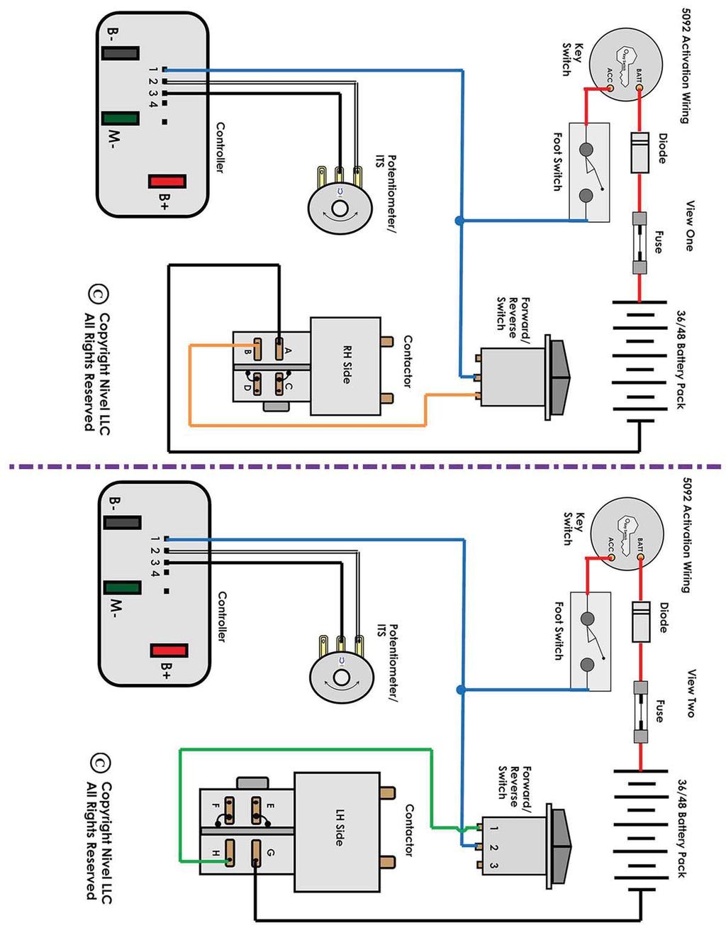
5 5092 Directional Contactor Power Cabling: We suggest using four gauge welding cable thoughout the system. All lugs are 5/16 hole size. You can purchas a universal cable kit and cut to length (P/N 29058). Some lugs in the kit will not be used. For Identif cation purposes we suggest putting color tape on each cable end to reflect what you see in the diagram. Tape does come with the kit (color). Again as you make connections to components use the double wrench meathod. On the diagram we have given connection point lettering, so you can follow the connections made on the diagram. From battery number one positive terminal connect a red coded cable to one side of the line contactor (leave actual connection to the battery loose for now). On the opp terminal connect a red coded cable to B+ on the controller. From B+ on the controller connect a cable to A1 on the motor. From A2 on the motor connect to directional contactor terminal A. From S2 on the motor connect a cable to directional contactor C. From S1 on the motor connect a cable to directional contactor B. From M- on the controller connect a cable to directional contactor D. From controller terminal B- connect a cable to battery number 6 negative terminal.

6
7


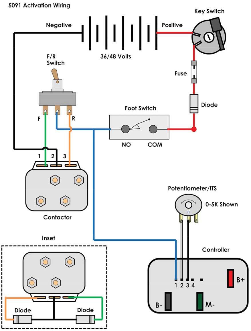
8 Directional Contactor Wiring 5091 Directional Contactor A D B C 36/48 V Positive Pos Neg Pos Fuse Line Contactor Page 11 Controller 36/48 V Negative S1 A1 Directional Contactor Pins 1, and 3 are connection points from Forward/Reverse Switch. Pin 2 is negative from B-. The use of 18 gauge wire is used. Motor S2 A2 P8
9 Activation Wiring For 5091 Contactor: The system consists of a Key Switch, Fuse, Diodes, Accelerator Switch, Forward/Reverse Switch, Contactor, Controller, Batteries, and Potentiometer/ITS. Some items are not included in this kit. The listed parts are for identity purposes. You must have a power source of nominal 36/48 volts. From the positive side of that source connect a positive 18 gauge wire (red) to the key switch. On the other key switch terminal connect a 18 gauge (red) wire to a 10 amp fuse. From the other side of the fuse connect a 18 gauge wire (red) to the anode side of one of the diodes included in this kit. Anode side is the solid black end. On the other end of the diode (white band cathode) connect a 18 gauge (red) wire to the COM side of the accelerator switch (foot switch). On the NO side of the accelerator switch connect a 18 gauge (blue) wire to pin one on the controller and the center terminal on the F/R switch. From either F/R terminal NO side connect a 18 gauge (orange) wire. Route the orange wire to one of the outer terminal on the contactor (does not matter at this point which one). On the other F/R NO terminal connect a 18 gauge (green) wire. Route the green wire to the other outside terminal on the contactor. On the center terminal on the contactor connect a 18 gauge (black) wire and route it to battery negative or B- on the controller. You can call the orange wire pin one on the contactor. Pin 2 can be called negative black wire. Pin 3 can be called the green wire. Caution: pin 1 and 3 are positive connections, and pin 2 is a negative connection! The pins are.250 male spade connectors. Locate the car s potentiometer or ITS. If the car is a 2 wire potentiometer connect a black 18 gauge wire to the center terminal. Route this black wire to pin 3 on the controller. From the controller pin 2 route a white wire to the potentiometer low side. Make sure you have the correct wipe before soldering. Test from the potentiometer center terminal to one of the outside pins that give you a 0 to 5K resistive wipe. Use 18 gauge wire. For 3 wire 5K to 0 wipe use the center pin and outer pin that creates a 5K to 0 resistive wipe. For cars using an ITS (Inductive Throttle Sensor) connect a 18 gauge black wire to pin 3 and a 18 gauge white wire to pin 2. On the ITS just pick a terminal it does not matter. In the event the car runs in reverse instead of what you consider forward just reverse the green wire with the orange wire. Diode connections on the contactor. Connect black 18 gauge wires to the anode (black end) of two diodes. Route those two wires to the same 18 black wire that connects to the center terminal on the contactor. Put all three wires in to one terminal and crimp. On one of the diodes (cathode end/white band) connect a green 18 gauge wire and connect to the green contactor wire. From the other diode (cathode/white band) connect a orange wire to the contactor orange wire. Use a connector large enough to accommodate both orange wire or both green wires. See inset on diagram. Note: if connecting any accessories on the key switch you must use a relay. P

10

11


12


13 Club Car Switches Connect these two wires together. BL/WH GR/WH Anti-Arcing Switch Remove Wires R/WH OR Optional Relay Back-Up Switch Connect these two wires together. Resistor GR BL WH 1/2 Speed Reverse Switch Remove wires from all the switch's. Store switches for later use or throw them away. Connect the Black Wire With White stripe to the Green Wire With White stripe that was on the Anti-Arcing Switch. Connect the solid Green Wire to the solid White Wire that was on the 1/2 speed reverse switch. The black wire just tape it up. For a Back Up Alarm connect the Orange and Red Wire with White stripe and the solid Orange wire to a normally open set of contacts on a relay. For relay activation connect a negative to one of the small terminals. On the other small coil terminal connect a wire from the reverse wire either on the Switch or Contactor. If you would like the 1/2 speed reverse option use a relay that has a single pole double throw design. Connect the Green wire to terminal NC and the White wire to terminal COM. Connect the Black wire to terminal NO. Connect one of the small coil terminals to negative and the other small coil terminal to the reverse wire on the Switch or Contactor. Single Pole Double Throw Relay = T9AP5D52-48 Potter&Brumfield (48 volt). Single Pole Double Throw Relay = T9AP5D52-36 Potter&Brumfield (36 volt). P13
SK1001 SPEED KIT For 48-volt Club Car DS Model Installation Instructions
 SK00 SPEED KIT For 48-volt Club Car 995-005 DS Model Installation Instructions SK00 Club Car DS Speed Kit Installation Instructions Thank you for purchasing our exclusive SK00 Speed Kit. We take great
Cruise Control Wiring
 Cruise Control Wiring By Matt Sandt, Revised 3-28-16 The approach described in this writing applies to solar car motor controls which use a potentiometer connected to a gas pedal. The potentiometer is
Contacts The moveable contact, which is the one affected by the armature is sometimes referred to as the hinge contact.
 Relays & Wiring 101 Basically, a relay is an electrically operated, remotely controlled switch. A simple electromagnetic relay is an adaptation of an electromagnet. It consists of a coil of wire surrounding
6945 (12v) 6944 (24V) installation instructions
 6944 (24V) installation instructions") 6945 (12v) 6944 (24V) installation instructions included: tools needed: Cordless drill Breezeeasy Fan Mounting brackets 1/4 Drill Bit 10mm Socket Hardware Pack 10mm Wrench Fuse Assembly Wire Stripper Crimper
6945 (12v) 6944 (24V) installation instructions included: tools needed: Cordless drill Breezeeasy Fan Mounting brackets 1/4 Drill Bit 10mm Socket Hardware Pack 10mm Wrench Fuse Assembly Wire Stripper Crimper
L/6.7L DODGE CUMMINS
 10/19/2012 2005-08 5.9/6.7 Dodge Cummins FlowMAX Lift Pump Kit # 1050310B - 1-2005-09 5.9L/6.7L DODGE CUMMINS BD FLOWMax V2 LIFT PUMP KIT Installation Instructions P/N # 1050310B PLEASE READ ALL INSTRUCTIONS
Not Included. Rear Half Harness
 Basic Light Kit 60102 Caution! Wear appropriate eye protection! Disconnect the battery or batteries. Place run/tow switch in tow position before disconnecting the batteries on models using that feature.
Instructions for Yamaha G14/G16/G19/G22 Models
 Instructions for Yamaha G14/G16/G19/G22 Models The Light Kit includes: (31483) Brakelight Connector Turn Signal Connector (1) Main Wire Harness with Positive & Negative In-line Fuses. (1) Head Light Switch.
29048, 29049, 29050, 29051, 29052, 29053, 29054,
 April 15, 2014 Lit. No. 29206, Rev. 11 29048, 29049, 29050, 29051, 29052, 29053, 29054, 29400 5 HARNESS KIT 3 PORT ISOLATION MODULE LIGHT SYSTEM w/3 PLUG SYSTEM HARNESSES Installation Instructions Read
UNIVERSAL GAUGE WIRE HARNESS
 2650-1797-00 UNIVERSAL GAUGE WIRE HARNESS For Installing Auto Meter Electric Speedometer, Tachometer, And Short Sweep Electric Oil Pressure, Water Temperature, Fuel Level, and Volt Meter Gauges. This harness
Your Legal Fuel Tank Source.
 February 23, 2015 IS# 808 Page 1 of 13 THANK YOU FOR PURCHASING A TRANSFER FLOW 40 GALLON TOOLBOX REFUELING SYSTEM. PLEASE READ THE FOLLOWING PROCEDURES CAREFULLY BEFORE STARTING THE INSTALLATION. CAUTION:
Grout Pump Automatic & Manual Troubleshooting Gas Wiring Diagram
 Grout Pump Automatic & Manual Troubleshooting 40-500 Gas Wiring Diagram Turn engine off and relieve hydraulic pressure and grout pressure before troubleshooting. Note: Typically there is a wiring diagram
BURGLAR ALARM KIT MODEL K-23. Assembly and Instruction Manual ELENCO
 BURGLAR ALARM KIT MODEL K-23 Assembly and Instruction Manual ELENCO Copyright 2017, 1989 ELENCO Electronics, Inc. Revised 2017 REV-R- 753223 No part of this book shall be reproduced by any means; electronic,
Zeon Control Pack Relocation Kit 78 Cable Length
 ORIGINAL INSTRUCTIONS SYMBOL INDEX SYMBOL EXPLANATION SYMBOL EXPLANATION Read All Product Literature Always Wear Leather Gloves Always Wear Hearing and Eye Protection Do Not Move People Zeon Control Pack
½ DODGE CUMMINS
 19 October 2012 2003-04½ Dodge Cummins FlowMAX Lift Pump Kit # 1050305B - 1-2003-04½ DODGE CUMMINS BD FlowMax LIFT PUMP KIT Installation Instructions P/N# 1050305B PLEASE READ ALL INSTRUCTIONS CAREFULLY
MODEL ELC-12/40-CVM-D BATTERY CHARGER
 NATIONAL RAILWAY SUPPLY MODEL ELC-12/40-CVM-D BATTERY CHARGER Installing, Operating and Service Instructions for the ELC-12/40-CVM-D Solid State Charger PLEASE SAVE THESE IMPORTANT SAFETY AND OPERATING
Trail Rocker Installation
 Trail Rocker Installation Instructions Customizable Trail Rocker Control System For Installing Painless Part Number: 57100 Manual #90616 Painless Performance Products recommends you, the installer, read
Toyota Tacoma Double Cab up A Toyota Tacoma Access Cab* up A. 3-5 Hours INSTALLATION GUIDE INSTALLATION TIME SKILL LEVEL
 INSTALLATION GUIDE APPLICATION MODEL YR PART # Toyota Tacoma Double Cab 2005 - up 75142-01A Toyota Tacoma Access Cab* 2005 - up 75142-01A INSTALLATION TIME 3-5 Hours Professional installation recommended
29048, 29049, 29050, 29051, 29052, 29053, 29054,
 May 1, 2018 Lit. No. 29206, Rev. 13 29048, 29049, 29050, 29051, 29052, 29053, 29054, 29400 7 HARNESS KIT 3 PORT ISOLATION MODULE LIGHT SYSTEM w/3 PLUG SYSTEM HARNESSES Installation Instructions Read this
D&D Motor Systems, Inc.
 D&D Motor Systems, Inc. Programmable Regen Controller Manual & Schematics BE ADVISED, D&D Motor Systems, Inc. does not design and manufacture controllers. We provide them as an extension to our existing
INSTALLATION INSTRUCTIONS FORD POWERSTROKE PICKUPS MODEL YEAR
 p p INSTALLATION INSTRUCTIONS FORD POWERSTROKE PICKUPS MODEL YEAR 2005-2006 www.dieselturbolifesaver.com Diesel Turbo Lifesaver (DTLS) is a computer controlled device that allows you to set an automatic
INSTALLATION INSTRUCTIONS
 INSTALLATION INSTRUCTIONS Models: 7105 & 7105TK Dodge Ram 1500 ('02 Current) Ram 2500 & 3500 '03 - Current with stock manual mirrors. IF YOU DO NOT CURRENTLY HAVE MANUAL MIRRORS, THE WRONG SET HAS BEEN
29048, 29049, 29050, 29051, 29052, 29053, 29054,
 April 15, 2014 Lit. No. 29206, Rev. 11 29048, 29049, 29050, 29051, 29052, 29053, 29054, 29400 5 HARNESS KIT 3 PORT ISOLATION MODULE LIGHT SYSTEM w/3 PLUG SYSTEM HARNESSES Installation Instructions Read
29048, 29049, 29050, 29051, 29052, 29053, 29054,
 April 15, 2014 Lit. No. 29225, Rev. 11 29048, 29049, 29050, 29051, 29052, 29053, 29054, 29400 5 HARNESS KIT 3 PORT ISOLATION MODULE LIGHT SYSTEM w/2 PLUG SYSTEM HARNESSES Installation Instructions Read
Installation Instructions for Lingenfelter GM 2500 Suburban & Yukon XL Auxiliary Fan System (with AC clutch controlled fan output)
") Installation Instructions for Lingenfelter 2007-2013 GM 2500 Suburban & Yukon XL Auxiliary Fan System (with AC clutch controlled fan output) PN L300080607 Revision - 1.1 Lingenfelter Performance Engineering
Installation Instructions for Lingenfelter 2007-2013 GM 2500 Suburban & Yukon XL Auxiliary Fan System (with AC clutch controlled fan output) PN L300080607 Revision - 1.1 Lingenfelter Performance Engineering
DODGE CUMMINS 24V ISB
 4 September 2013 1998-2002 Dodge Cummins FlowMAX Lift Pump Kit # 1050301C - 1-1998-02 DODGE CUMMINS 24V ISB FLOWMAX LIFT PUMP KIT I n s t a l l a t i o n I n s t r u c t i o n s Part# 1050301C PLEASE READ
Trail Rocker Installation Instructions
 Trail Rocker Installation Instructions Manual #90581 For Installing Painless Part Numbers: 57002 Painless Performance Products recommends you, the installer, read this installation manual from front to
Contents. TCS/ Driver Mod Installation Manual
 Contents Introduction... 1 TCS Packing List... 3 Tools Needed for Installation... 4 How to Properly Solder... 5 Soldering Standard Butt Connection... 5 Soldering T Connection... 6 How to Properly Crimp...
Installation Instructions
 Installation Instructions Jeep JK Unlimited (2007 Present) Mounting Bracket and Air Line System Kit for ARB On-Board Twin Air Compressor (CKMTA12) Made in the USA Kit Contents: 1 Bracket for ARB Compressor
HARNESS KIT 3 PORT ISOLATION MODULE LIGHT SYSTEM. Parts List and Installation Instructions CAUTION
 May 1, 2018 Lit. No. 92991, Rev. 00 HARNESS KIT 3 PORT ISOLATION MODULE LIGHT SYSTEM Parts List and Installation Instructions Read this document before installing the snowplow. See your sales outlet/website
Trail Rocker Installation Instructions
 Trail Rocker Installation Instructions Manual #90580 For Installing Painless Part Numbers: 57000 and 57001 Painless Performance Products recommends you, the installer, read this installation manual from
29048, 29049, 29050, 29051, 29052, 20953, 29054,
 July 15, 2008 Lit. No. 29225, Rev. 06 29048, 29049, 29050, 29051, 29052, 20953, 29054, 29400-2 HARNESS KIT 3-PORT ISOLATION MODULE LIGHT SYSTEM w/2-plug SYSTEM HARNESSES Installation Instructions Read
Model: SE-4020-CA Automatic Battery Charger
 OWNERS MANUAL Model: SE-4020-CA Automatic Battery Charger PLEASE SAVE THIS OWNERS MANUAL AND READ BEFORE EACH USE. This manual will explain how to use the battery charger safely and effectively. Please
Club Car 1515 to Curtis 1268 Conversion
 Club Car 1515 to Curtis 1268 Conversion Installation Instructions 62-12685501CKXI Rev. 03 4/17/14 Page 1 of 7 1515 to Curtis 1268 Conversion Installation Instructions Before you start turn Tow/Run switch
Ford Racing 4.6L 3V Crate Engine Control Pack
 Ford Racing 4.6L 3V Crate Engine Control Pack Installation Time: 3-6 hours on a Foxbody Mustang Tools Required: Basic English and Metric Socket and Wrench Set Flat and Phillips Screwdrivers Torx bits Hammer
Troubleshooting Guide for Stamford Generators
 Bulletin Number: Type of Bulletin: Trouble Shooting Products Affected: TracStar 630/900 Dates Manufactured: All Date of Notification: July 2009 Description of Bulletin This is a troubleshooting guide for
TOYOTA YARIS HATCHBACK INTERIOR LIGHT UPGRADE Preparation
 Preparation Part Number PTS21-52062-08 NOTE: Part number of this accessory may not be the same as the part number show Kit Contents Item # Quantity Reqd. Description 1 1 12 Light Guide 2 1 7 Light Guide
1501 Industrial Way N., Toms River, NJ Fax: PACKING LIST INSTALLATION INSTRUCTIONS
 1/6/04 1501 Industrial Way N., Toms River, NJ 08755 732-349-2109 Fax:732-244-0867 MODERATE - Installation requires metric tools and possibly cutting and drilling. The ability to closely follow instructions
Photo below shows the yellow wire on the left and the black on the right.
 2000 pound lift installation photos and troubleshooting helps This photo shows a wired lift. Shown in this photo User will install: From the control cable: small blue wire on front solenoid terminal small
Technical Support (707)
") Installation Instructions CONSOLE MEGASHIFTER Fits: 1982-1992 Camaro & Firebird w/automatic Transmission *except 1988-1992 Firebird Formula Model Catalog # 80692 WORK SAFELY! For maximum safety, perform
Installation Instructions CONSOLE MEGASHIFTER Fits: 1982-1992 Camaro & Firebird w/automatic Transmission *except 1988-1992 Firebird Formula Model Catalog # 80692 WORK SAFELY! For maximum safety, perform
Triumph Street Triple VSM Grip Heater Install
 Triumph Street Triple VSM Grip Heater Install Introduction: With winter fast approaching and with painful memories of last winter riding with the club it was time to do something about getting some grip
Installation Instructions
 Installation Instructions AMP RESEARCH Power Step by Bestop Automatic Retracting Running Board Vehicle Application Nissan Titan King Cab 2004 and newer (5 ft.) Part Number: 75106-01 Nissan Titan Crew Cab
B29048, B29049, B29050, B29051, B29053, B
 May 1, 2011 Lit. No. 48266, Rev. 05 B29048, B29049, B29050, B29051, B29053, B29400-5 HARNESS KIT 3-PORT ISOLATION MODULE LIGHT SYSTEM w/2-plug SYSTEM HARNESSES Installation Instructions Read this document
HARNESS KIT 3-PORT ISOLATION MODULE LIGHT SYSTEM
 October 1, 2018 Lit. No. 92988, Rev. 00 72199 HARNESS KIT 3-PORT ISOLATION MODULE LIGHT SYSTEM Parts List and Installation Instructions Read this document before installing the harness kit. See your sales
Instructions on installing the R/R to the front battery cover.
 April, 2008 Instructions on installing the R/R to the front battery cover. Please read all of the steps so you will be familiar with the complete relocation installation first. The purpose of this relocation
ROUSH Active IO Exhaust. Installation Instructions P/N: (R LITE) Fastback GT Convertible GT V8
 Fastback GT Convertible GT V8") Installation Instructions P/N: 422128 (R1318-5231LITE) Fastback GT Convertible GT V8 39555 Schoolcraft Rd, Plymouth MI, 48170 800.59.ROUSH ROUSH Active IO Exhaust Installation Instructions P/N: 422128
Installation Instructions P/N: 422128 (R1318-5231LITE) Fastback GT Convertible GT V8 39555 Schoolcraft Rd, Plymouth MI, 48170 800.59.ROUSH ROUSH Active IO Exhaust Installation Instructions P/N: 422128
CHEVY CAMARO Four panel Sequential LED Taillight kit installation guide
 1978-81 CHEVY CAMARO Four panel Sequential LED Taillight kit installation guide Kit Contents: 4 LED panels 1 power wire with t-tap 2 driver side LED harnesses, 24 2 passenger side LED harnesses, 48 4 LED
½ DODGE CUMMINS
 7 April 2009 2003-04½ Dodge Cummins FlowMAX Lift Pump Kit # 1050305-1 - 2003-04½ DODGE CUMMINS BD FlowMax LIFT PUMP KIT Installation Instructions P/N# 1050305 PLEASE READ ALL INSTRUCTIONS CAREFULLY BEFORE
PRXB EXHAUST BRAKE HIGH PERFORMANCE
 HIGH PERFORMANCE PRXB EXHAUST BRAKE C44059, C4406, C44063, C44065 APPLICATION 994-2002 DODGE RAM AUTOMATIC TRUCKS EQUIPPED WITH 47RE TRANSMISSIONS WITH 5.9L, 24 VALVE CUMMINS DIESEL ENGINES GETTING STARTED
Fitting Instructions
 Dual Battery Kit Fitting Instructions Fitting Instructions We recommend that the is installed by a licensed auto-electrician. WARNING: Like any addition to your 12v set-up, ensure you ve installed a fuse
Installationn Instruction Manual
 Table of Contents Supplied Kit Parts.Page 2 Required Tool List Page 2 Step by Step Installation Instructions Pages 3-6 Battery Requirements.Page 6 Operation Page 7 Maintenance Page 7 Wiring Diagrams..Page
Installation Instructions for Chevrolet Colorado, GMC Canyon, LT, Z71, With Factory Fog Lights
 Installation Instructions for 2015-2018 Chevrolet Colorado, GMC Canyon, LT, Z71, With Factory Fog Lights This kit is designed to allow use of your factory fog light operation along with an addition auxiliary
INSTALLATION INSTRUCTIONS
 INSTALLATION INSTRUCTIONS Thank you for purchasing ROLTECTM Electric Hopper Conversion. Agri-Cover, Inc. proudly manufactured this hardware using superior quality materials and workmanship. With proper
INSTALLATION INSTRUCTION
 1551 S. Vineyard Avenue Ontario, CA 91761 (909) 923-1973 INSTALLATION INSTRUCTION Club Car Precedent Installation Notes CURTIS 1234, 1236 OR 1238 AC INDUCTION MOTOR/ CONTROLLER REVISION: B This kit is
Track Rocker Installation Instructions
 Track Rocker Installation Instructions Customizable Track Rocker Control System For Installing Painless Part Number: 58100 Track Rocker Relay Center Manual #90641 Painless Performance Products recommends
L/6.7L DODGE CUMMINS
 6/15/2016 #1050310D 2005-09 5.9/6.7 Dodge Cummins FlowMAX Lift Pump Kit (I-00170) - 1-2005-09 5.9L/6.7L DODGE CUMMINS BD FLOWMAX LIFT PUMP KIT Installation Instructions P/N # 1050310D PLEASE READ ALL INSTRUCTIONS
49663, 49664, Wiring Conversion Kits. Installation Instructions CAUTION. Read this document before installing the snowplow.
 December 1, 2011 Lit. No. 49666, Rev. 00 Wiring Conversion Kits Installation Instructions Read this document before installing the snowplow. See your sales outlet/web site for specific vehicle application
CP 634 DELUXE 4-CHANNEL KEYLESS ENTRY SYSTEM
 CP 634 DELUXE 4-CHANNEL KEYLESS ENTRY SYSTEM Installation And Operation Manual MEGATRONIX VAN NUYS, CA U.S.A. CP634 1 REMOTE CONTROL CONVENIENT SYSTEM INSTALLATION & OPERATION INSTRUCTIONS INTRODUCTION
Addictive Desert Designs
 Preparation: Disconnect the negative battery terminal. Park the vehicle on level ground and set the emergency brake. We recommend reading through the installation instructions in whole before performing
IMPORTANT SAFETY INSTRUCTIONS
 1163714 1.5 AMP 12VOLT TRICKLE 1.5 AUTOMATIC AMP AUTOMATIC TRICKLE 1.5 AMP AUTOMATIC 12V12VOLT BATTERY CHARGER IMPORTANT SAFETY INSTRUCTIONS 1. SAVE THESE INSTRUCTIONS This product offers a wide range
AUXILIARY BATTERY BOX INSTALLATION INSTRUCTIONS
 AUXILIARY BATTERY BOX INSTALLATION INSTRUCTIONS The original TOMMY GATE hydraulic lift Assembling the Auxiliary Battery Box 1. Remove the cover from the auxiliary battery box by removing the two nuts and
Section II - Installation Procedures Part Number : Accessory Code IL1 Kit Contents. Color Applicability/Trim Level. Hardware Bag Contents
 Document # 10.21.00 PIO/DIO 01/14/09 TOYOTA Rav-4 2009- INTERIOR InteriorLIGHT Light UPGRADE Upgrade Part Number : 00016-00065 Accessory Code IL1 Kit Contents Color Applicability/Trim Level Item # Quantity
AIR INTAKE EMERGENCY SHUT-OFF VALVE C50207 AIR INTAKE SHUT-OFF VALVES APPLICATION FORD 6.7L POWERSTROKE.
 AIR INTAKE EMERGENCY SHUT-OFF VALVE C50207 AIR INTAKE SHUT-OFF VALVES APPLICATION 2011-2016 FORD 6.7L POWERSTROKE www.powerhalt.com Thank you for your purchase of a PowerHalt Air Intake Emergency Shut-Off
#TL T EA888 GEN 3 FUELING SYSTEM/ INSTALLATION INSTRUCTIONS
 #TL100069 2.0T EA888 GEN 3 FUELING SYSTEM/ INSTALLATION INSTRUCTIONS Notes: These instructions were written for a North American specification MkVII GTI. Other models, like the Golf R, are similar. When
42 Series Step. Owner's Manual #842A. Equipped with a Permanent Magnet Motor. Table of Contents
 Owner's Manual #842A 10/05 Kwikee #1422258, Rev. 0A ED 42 Series Step Equipped with a Permanent Magnet Motor D IS C O N TI N U For steps with Control Unit 909510000 and steps without Control Units Table
White Light CLASSIC PEDAL KIT. Assembly Instructions WHEN YOU CAN T BUY IT BUILD IT. StewMac RARE / VINTAGE / HARD TO GET
 Sheet #i-2206 Updated 5/18 StewMac White Light CLASSIC PEDAL KIT Kit case is unpainted IN COLLABORATION WITH EarthQuakerDevices Assembly Instructions The White Light Overdrive is based on vintage overdrives
AUTO CHARGE 11 MODEL #: XX. AUTOMATIC BATTERY CHARGER U.L. Configuration INSTRUCTION MANUAL
 INSTRUCTION MANUAL AUTO CHARGE 11 AUTOMATIC BATTERY CHARGER U.L. Configuration MODEL #: 091-11-XX NOTE : This charger is designed for vehicles with dual batteries and negative ground. CAUTION This unit
PN PONTIAC FIREBIRD. Kit Contents: Four Panel Sequential LED Tail Light Kit Installation Guide
 1969 PONTIAC FIREBIRD Four Panel Sequential LED Tail Light Kit Installation Guide Kit Contents: 4 LED panels 4 rubber grommets 1 power wire 2 pigtail harness kits 2 crimp terminal kits PN 1100569 1969
L DODGE CUMMINS BD FLOWMAX LIFT PUMP KIT
 6/15/2016 #1050311D 2010-12 6.7 Dodge Cummins FlowMAX Lift Pump Kit (I-00329) - 1-2010-12 6.7L DODGE CUMMINS BD FLOWMAX LIFT PUMP KIT Installation Instructions P/N # 1050311D PLEASE READ ALL INSTRUCTIONS
PRXB EXHAUST BRAKE MAXIMUM EXHAUST FLOW DESIGN
 MAXIMUM EXHAUST FLOW DESIGN PRXB EXHAUST BRAKE C44072/C44073/C44074/C44075/C44076 APPLICATION: 994-2002 DODGE RAM TRUCKS W/5.9L CUMMINS DIESEL ENGINES WITH MANUAL & AUTOMATIC TRANSMISSIONS STOCK DODGE
HARNESS KIT 3 PORT ISOLATION MODULE LIGHT SYSTEM
 January 1, 2016 Lit. No. 92935, Rev. 01 52101 HARNESS KIT 3 PORT ISOLATION MODULE LIGHT SYSTEM Parts List and Installation Instructions Read this document before installing the snowplow. See your sales
Turn Signal / Horn Kit PN 7101 by All years Polaris RZR 1000 and RZR 900, 900-4, 900 trail, 900S and 900XC STOP - THIS KIT IS DESIGNED
 All years Polaris RZR 1000 and 1000-4 2015 RZR 900, 900-4, 900 trail, 900S and 900XC STOP - THIS KIT IS DESIGNED SPECIFICALLY FOR ALL YEAR AND MODEL POLARIS RZR 1000 AND 1000-4. ALSO THE 2015 POLARIS RZR
99 Ford Ranger EV EPT2 Conversion Wiring Instructions
 99 Ford Ranger EV EPT2 Conversion Wiring Instructions There are two electrical systems. One 144 volt high current traction circuit and one low voltage control and accessory circuit. The low voltage circuit
B U I C K G R A N D N A T I O N A L S E Q U E N T I A L L E D T A I L L I G H T K I T P N INSTALLATION GUIDE
 B U I C G R A N D N A T I O N A L S E Q U E N T I A L L E D T A I L L I G T I T P N 1 1 0 0 8 8 6 INSTALLATION GUIDE Please refer to Invoice for full warranty information. Digi-Tails is not a licensed
49663, 49664, Wiring Conversion Kits. Parts List and Installation Instructions CAUTION. Read this document before installing the snowplow.
 December 1, 2014 Lit. No. 49666, Rev. 01 49663, 49664, 49665 Wiring Conversion Kits Parts List and Installation Instructions Read this document before installing the snowplow. See your sales outlet/web
½ DODGE CUMMINS
 15 June 2016 #1050305D 2003-2004½ Dodge Cummins FlowMAX Lift Pump Kit (I-00169) - 1-2003-04½ DODGE CUMMINS BD FLOWMAX LIFT PUMP KIT Installation Instructions P/N# 1050305D PLEASE READ ALL INSTRUCTIONS
I n s t a l l a t i o n I n s t r u c t i o n s
 MG Midget and Austin-Healey Sprite Supercharger Alternator Conversion FOR 1961-1967 Midget (up to car# G-AN4-60459) and Sprite (up to car# H-AN9-72040) PART # 130-108 440 Rutherford St. P.O. Box 847 Goleta,
INSTALLATION INSTRUCTIONS
 INSTALLATION INSTRUCTIONS FUEL SURGE TANK INSTALLATION KIT 1999-2006 BMW E46 COUPE Document# 19-0056 Support: info@radiumauto.com Note: This kit was designed for a standard single pump Radium Engineering
Heater/Defroster Installation Instructions
 1301 39 th Street NW, Suite 2 * Fargo, ND 58102 * Toll Free 866.764.0616 * Fax 701.446.0103 * www.gemcar.com Service Instructions Heater/Defroster Installation Instructions Models: All 2005 - Current Part
Owner s Manual. Expansion Kits: GP-RV-80E GP-RV-95E GP-RV-160E
 powered by Expansion Kits: GP-RV-8E GP-RV-E RV Power Kits: GP-RV-8 GP-RV- Weekender SW Owner s Manual shown here GP-RV-8E GP-RV-E GP-RV-8 GP-RV- Standard Kits Expansion Kits PART GP-RV-8/95/ * or SW *
Vehicle Wiring Harness and Cab Control
 August 15, 2015 Lit. No. 43777, Rev. 00 Vehicle Wiring Harness and Cab Control For Low-Profile, Two-Stage Tailgate Spreaders Installation Instructions Read this document before installing the spreader.
Installation Instructions
 Installation Instructions Jeep JK 2-Door (2011 Present) Mounting Bracket and Air Line System Kit for ARB On-Board Twin Air Compressor (CKMTA12) Made in the USA Kit Contents: 1 Flat Bracket 1 Formed Bracket
29048, 29049, 29050, 29051, 29052, 20953, 29054,
 May 1, 2008 Lit. No. 29206, Rev. 05 29048, 29049, 29050, 29051, 29052, 20953, 29054, 29400-2 HARNESS KIT 3-PORT ISOLATION MODULE LIGHT SYSTEM w/3-plug SYSTEM HARNESSES Installation Instructions Read this
LESTRONIC II BATTERY CHARGER MODEL 07210
 LESTRONIC II BATTERY CHARGER MODEL 07210 PLEASE SAVE THESE IMPORTANT SAFETY AND OPERATING INSTRUCTIONS For correct operation of the equipment, it is important to read and be familiar with this entire manual
SYSTEM OPERATION IMPORTANT CAUTIONS
 SYSTEM OPERATION The system is turned on by placing the gear shift lever in the reverse position. The green light on the cab Control Box will illuminate to indicate the system is operating. When an object
Crane Systems GREER COMPANY. LALT 1151L System for Lattice Cranes. Installation and Calibration Manual. 1 of 39
 LALT 1151L System for Lattice Cranes Installation and Calibration Manual 1 of 39 This manual is designed to guide the fully trained and experienced crane operator in the correct installation and calibration
Installation Instructions MX-5 Dual Air Horns
 440 Rutherford St. P.O. Box 847 Goleta, CA 93117 1-800-667-7872 FAX 805-692-2525 www.mossmotors.com Tools required: Phillips screwdriver, 8mm, 10mm and 21mm sockets, 8mm and 10mm combination wrenches,
Installation Instructions B&M StarTek Starter Fits: Ford & Mercury (3/4 Depth) w/sb V8, 289, 302, & 351W.
 w/sb V8, 289, 302, & 351W.") Installation Instructions B&M StarTek Starter Fits: 1965-1995 Ford & Mercury (3/4 Depth) w/sb V8, 289, 302, & 351W. Catalog # 77100 WORK SAFELY! For maximum safety, perform this installation on a clean,
Installation Instructions B&M StarTek Starter Fits: 1965-1995 Ford & Mercury (3/4 Depth) w/sb V8, 289, 302, & 351W. Catalog # 77100 WORK SAFELY! For maximum safety, perform this installation on a clean,
HARNESS KIT 3 PORT ISOLATION MODULE LIGHT SYSTEM
 September 1, 2016 Lit. No. 73981, Rev. 00 73977 HARNESS KIT 3 PORT ISOLATION MODULE LIGHT SYSTEM Parts List and Installation Instructions Read this document before installing the snowplow. See your sales
INSTALLATION INSTRUCTIONS FUEL SURGE TANK KIT
 INSTALLATION INSTRUCTIONS FUEL SURGE TANK KIT BMW E46 3-Series, Excl Convertible Document: 19-0056 Support: info@radiumauto.com Relieve fuel pressure in vehicle before beginingthe installation. Disconnect
HARNESS KIT 3-PORT ISOLATION MODULE LIGHT SYSTEM
 July 15, 2018 Lit. No. 92989, Rev. 00 79147 HARNESS KIT 3-PORT ISOLATION MODULE LIGHT SYSTEM w/led-style VEHICLE LIGHTING Parts List and Installation Instructions Read this document before installing the
VEHICLE SPECIFIC ELECTRICAL INSTALLATION INSTRUCTIONS
 WESTERN PRODUCTS, P.O. BOX 245038, MILWAUKEE, WI 53224-9538 Lit. No. 63723 VEHICLE SPECIFIC ELECTRICAL INSTALLATION INSTRUCTIONS FORD BRONCO F-150 4x4 F-250/350 4x4 and 2WD FORD SUPER DUTY 1980-1991 Model
Aopec Dual Battery Kit Fitting Instructions
 AOPEC USA LLC. 1911 US Hwy 301 Suite 460 Tampa, FL 33619 Tel: 813-450-2156 Fax: 813-450-2638 www.aopec.com Aopec Dual Battery Kit Fitting Instructions Aopec Dual Battery Kit Fitting Instructions Fitment
Installation Instructions
 Instructions Created by an: DIY Underhood LED Lighting Kit (SKU# DIY-E-UHLK) Installation Instructions NOTICE: This Under Hood Light Kit was installed on a 2002 Toyota Tacoma. However, these instructions
Club Car 1510 to Curtis 1268 Conversion
 Club Car 1510 to Curtis 1268 Conversion Installation Instructions 62-12685501CKI Rev. 05 7/18/14 Page 1 of 7 1510 to Curtis 1268 Conversion Installation Instructions Before you start turn Tow/Run switch
***THE OWNER'S MANUAL MUST BE GIVEN TO THE END USE CUSTOMER AFTER COMPLETING THE INSTALLATION.***
 INSTALLATION INSTRUCTIONS FOR THE MOTOR TRIKE HARLEY MECHANICAL REVERSE 1999-2006 FIVE SPEED FLH LAST UPDATED: OCTOBER 2011 AS THE INSTALLER OF THIS MECHANICAL REVERSE, YOU MUST BECOME FAMILIAR WITH PROPER
SP6. Automatic Battery Charger. Model
 Model SP6 Automatic Battery Charger OWNERS MANUAL PLEASE SAVE THIS OWNERS MANUAL AND READ BEFORE EACH USE. This manual will explain how to use the charger safely and effectively. Please read and follow
INSTALL INSTRUCTIONS
 INSTALL INSTRUCTIONS Models: 6005 & 6005TK (For Non Electric Mirrors) GM CK Body Style If your stock mirrors are stock electric the wrong set has been ordered. Do not attempt to manually extend or retract
HARNESS KIT 3 PORT ISOLATION MODULE LIGHT SYSTEM
 September 1, 2016 Lit. No. 73980, Rev. 01 73973 HARNESS KIT 3 PORT ISOLATION MODULE LIGHT SYSTEM Parts List and Installation Instructions Read this document before installing the snowplow. See your sales
RAY ELECTRIC OUTBOARDS, INC.
 RAY ELECTRIC OUTBOARDS, INC. ELECTRICAL REPAIR MANUAL Model E2 (Variable Speed) Applicable to Serial #400 and greater Ray Electric Outboards, Inc. 908 NE 24 th Lane Cape Coral, FL 33909 (239) 574-1948
Spreader and Vehicle Battery Kits
 May 5, 20 Lit. No. 922, Rev. 04 and Vehicle Battery Kits Hopper s Parts List and Installation Instructions CAUTION Read this document before installing the and Vehicle Battery Kit. CAUTION Use standard