INSTALLATION INSTRUCTION
|
|
|
- Collin Allen
- 6 years ago
- Views:
Transcription
 923-1973 INSTALLATION INSTRUCTION Club Car Precedent")
1 1551 S. Vineyard Avenue Ontario, CA (909) INSTALLATION INSTRUCTION Club Car Precedent Installation Notes CURTIS 1234, 1236 OR 1238 AC INDUCTION MOTOR/ CONTROLLER REVISION: B
2 This kit is designed to integrate a HPEV AC Induction Motor and a Curtis AC controller model 1234, 1236 or 1238 to a Club Car Precedent. Verify the kit contains the following: 1- AC motor 1- Curtis Motor controller (1234, 1236 or 1238 model) 1- Controller mounting plate 1- Upper mounting plate bracket 2- Lower support brackets 1- Wire Harness kit (system and dash harness) 1- Multi Function Display (mounting hardware included) 1- Menu button 3- Motor cables (14 ½ ) 1- Contactor to controller (+) red cable (15 ) 1- Battery to contactor (+) red cable (20 ) 1- Battery to controller ( ) black cable (20 ) 4- Battery interconnect cables (17 ) 1- Battery interconnect cable (8 ) 3- ¼ x 2 screws 4- ¼ x 1 ¼ screws 4- ¼ x 1 screws 9- ¼ x ½ screws 11- ¼ flat washers 11- ¼ lock washers 2- ¼ x ¾ self taping screws INSTRUCTIONS: COMPONENTS REMOVAL & PREPARATION 1. Turn ON/OFF Switch to OFF position and remove key from key switch. 2. Remove all battery cables. These will be replaced with heavier gauge cables that are included in the kit. 3. Remove the two middle batteries to facilitate access to the stock controller. Remove the rear motor cover. 4. Remove the car dash (consult with service manual). Unplug any connectors. The dash will be modified at later steps. Page 2 of 13

3 5. Remove the rear controller dust cover (motor area). Disconnect all the connectors. Do not cut any wires at this time. The original stock wire harness will be re-used. 6. Remove the stock motor. Save the 5/16 bolt that was used to fasten the lower portion of the motor; it will be reused when installing the new AC motor. 7. Remove the stock controller plate by unscrewing the black screw located at the top plate. Remove and save the following items from the stock controller plate: a. Charge computer b. Stock Contactor. Note: The contactor is removed by sliding it up. Do not break the retainer legs. Discard the resistor across the main terminals. c. Controller plate black screw 8. Mark and cut the rear controller plastic opening. See picture. Page 3 of 13


4 AC SYSTEM COMPONENT INSTALLATION 1. Install the charge computer in the supplied controller plate. Use two ¼ x ½ screws, two flat and two lock washers. Do not over tighten the screws. Make sure that no screws protrude to the other side of the plate since the controller will be installed on that area. See picture for location. 2. Install the lower support brackets. See above picture for hole locations. Use four ¼ x 1 screws, flat and lock washers. Make sure that the screws do not protrude to the other side of the plate. The lower support bracket should create a hook or gap where the controller plate will be mounted in the car. See pictures. Page 4 of 13


5 3. Install the contactor by sliding it until the retainer bottoms out in the opening. The contactor body must be located on the motor side, similar to the stock location. Page 5 of 13


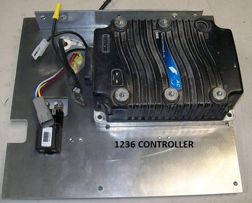
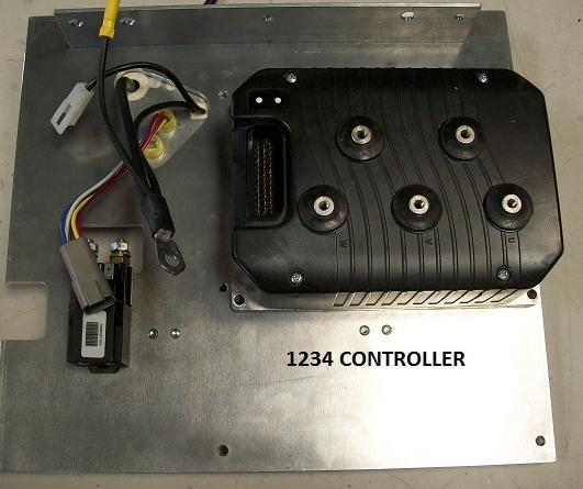
6 4. Install the upper mounting plate bracket. The upper mounting bracket is facing the motor side of the car. Use three ¼ x ½ screws, flat and lock washers. There is no need to fully tighten the screws at this step. The bracket s wider side will be mounted on top of the car similar to the stock controller bracket. 5. Install the AC controller. Similar to the stock controller, the controller is mounted on the motor side of the car. Depending on the controller used in a particular application, different sized screws will be used. For 1238 and 1236 controllers use four ¼ x 1¼ screws, and lock washers. For 1234 controller, use four ¼ x ½ screws, and lock washers. The following picture shows the location of the mounting holes. Page 6 of 13

7 Page 7 of 13


8 6. Install the AC controller plate in the car. The lower support bracket should insert the battery pack tray. The upper bracket should rest on top of the battery pack tray. Reuse the black screw saved from the removal of the stock controller. Use the supplied two ¼ x ¾ self tapping screws. Once these three screws are secured, proceed to tighten the upper bracket to the plate screws that were loosely installed earlier. See pictures. 7. Install the supplied red 15 cable from the contactor s switched side to the controller at the fuse end. See picture. Page 8 of 13

 positive side of the pack.")
9 8. Install the supplied 20 black cable from the controller to the negative side of the pack. Also connect the charge computer negative cable from the controller to the negative side of the battery pack. The cable is routed through the plate s side access cutout. 9. Install the red 20 cable from contactor s Hot side to the (+) positive side of the pack. Make sure that the terminal lug does not touch the plate. As an added precaution a cable boot may be used. Page 9 of 13

 to the Hot side of the contactor. Cut the stock quick disconnect terminal and install a 5/16 ring terminal.")
10 10. Route the stock wiring harness through the side access cutout 11. Install the supplied wire system wire harness. Connect the black 35 pin connector to the controller and the white 16 and 4 pin connectors to the stock harness. 12. Install the pink wire from the stock harness that provides power to system components (charge computer, dash, etc.) to the Hot side of the contactor. Cut the stock quick disconnect terminal and install a 5/16 ring terminal. Page 10 of 13


11 13. Re-connect the stock contactor coil wires (Light blue and Blue/ white). 14. Locate the 6 pin grey connector from the stock harness. Locate and cut the brown/ white wire. Install a male ¼ quick disconnect and connect to the brown wire from the new system harness. 15. Reconnect all the charge computer connections. 16. Cut the quick disconnect terminals that were connected to the stock Run / Tow switch (Light green and pink wires). Splice these wires together. The Run/ Tow switch is no longer needed. Page 11 of 13

12 17. Proceed to secure any loose and/or excess wires to avoid any damage. 18. Install the AC motor. Use the supplied three ¼ x 2 screws, flat and lock washers. Reuse the stock 5/16 bottom bolt. 19. Install the 14 ½ motor cables between the motor and controller. Note the connection phase designation i.e. U, V & W. DASH MODIFICATION 1. Remove the stock harness from the dash. 2. Remove the yellow charge light and install golf street switch in place. 3. Relocate the reverse buzzer to under the seat. Connect the Black/blue wire quick disconnect terminal to the negative and yellow wire to the positive side. 4. Cut a 2 1/16 (52 mm) hole in the dash to install the display. Install the display with the included hardware. 5. Drill a 3/8 hole near the display for the menu button. Install the menu button by securing the retainer ring. Page 12 of 13


13 6. Install the kit dash harness. The harness has a plastic retainer to secure it to the dash similar as the stock harness. 7. Connect the harness to the dash components. The connections are the following: a. Key Switch: Blue and Green b. Golf-Street Switch: Blue and Brown c. Menu Button: Blue and White/ Red d. Multi function Display: White 8 pin connector 8. Re-install the dash and reconnect the stock lighting system. 9. Re-install the two middle batteries. Reconnect the batteries with the supplied batteries cables. Page 13 of 13
INSTALLATION INSTRUCTION. Club Car Precedent Lithium Battery Pack Installation Notes
 1551 S. Vineyard Avenue Ontario, CA 91761 (909) 923-1973 INSTALLATION INSTRUCTION Club Car Precedent Lithium Battery Pack Installation Notes REVISION: A Date: 11-12-16 Disclaimer: HPEVS assumes that the
INSTALLATION INSTRUCTION
 620 Magnolia Ave. Suite B Ontario, CA 91762 (909) 923-1973 INSTALLATION INSTRUCTION Club Car Precedent Lithium Battery Pack Installation Notes Including Cars with Installed HPEVS Drive Systems REVISION:
INSTALLATION INSTRUCTIONS
 1551 S. Vineyard Avenue Ontario, CA 91761 (909) 923-1973 INSTALLATION INSTRUCTIONS Club Car DS Installation Notes CURTIS 1234, 1236 OR 1238 AC INDUCTION MOTOR/ CONTROLLER Installation Instructions Club
OBC (On-Board Computer) By-pass Kit Installation Instructions Lester Electrical By-pass Kit #38836 for use with Club Car Precedent and DS vehicles
 By-pass Kit Installation Instructions Lester Electrical By-pass Kit #38836 for use with Club Car Precedent and DS vehicles") OBC (On-Board Computer) By-pass Kit Installation Instructions Lester Electrical By-pass Kit #38836 for use with Club Car Precedent and DS vehicles The Lester Electrical OBC (On-Board Computer) Bypass Kit
OBC (On-Board Computer) By-pass Kit Installation Instructions Lester Electrical By-pass Kit #38836 for use with Club Car Precedent and DS vehicles The Lester Electrical OBC (On-Board Computer) Bypass Kit
OBC (On-Board Computer) By-pass Kit Installation Instructions Lester Electrical By-pass Kit #38836 for use with Club Car
 By-pass Kit Installation Instructions Lester Electrical By-pass Kit #38836 for use with Club Car") OBC (On-Board Computer) By-pass Kit Installation Instructions Lester Electrical By-pass Kit #38836 for use with Club Car Precedent and DS vehicles (Only compatible with OBC/Car that has a 6 Pin Deutsch
OBC (On-Board Computer) By-pass Kit Installation Instructions Lester Electrical By-pass Kit #38836 for use with Club Car Precedent and DS vehicles (Only compatible with OBC/Car that has a 6 Pin Deutsch
INSTALLATION INSTRUCTIONS
 1551 S. Vineyard Avenue Ontario, CA 91761 (909) 923-1973 INSTALLATION INSTRUCTIONS E-Z-GO Installation Notes CURTIS 1234, 1236 OR 1238 AC INDUCTION MOTOR/ CONTROLLER EZ-GO Curtis Controller Installation
Club Car 1510 to Curtis 1268 Conversion
 Club Car 1510 to Curtis 1268 Conversion Installation Instructions 62-12685501CKI Rev. 05 7/18/14 Page 1 of 7 1510 to Curtis 1268 Conversion Installation Instructions Before you start turn Tow/Run switch
Bucket Harness. Installation Instructions. for Electric Club Car Precedent
 Bucket Harness for Electric Club Car Precedent Installation Instructions Electric Club Car Precedents manufactured after January 1, 2008 require an additional harness to allow the installation of light
INSTALLATION INSTRUCTIONS. Yamaha G19 Installation Notes
 620 Magnolia Avenue Suite B Ontario, CA 91762 (909) 923-1973 INSTALLATION INSTRUCTIONS Yamaha G19 Installation Notes CURTIS 1232, 1234, 1236 OR 1238 AC INDUCTION MOTOR/ CONTROLLER Yamaha G 19 Installation
D&D Motor Systems, Inc.
 D&D Motor Systems, Inc. Programmable Regen Controller Manual & Schematics BE ADVISED, D&D Motor Systems, Inc. does not design and manufacture controllers. We provide them as an extension to our existing
PN PONTIAC FIREBIRD. Kit Contents: Four Panel Sequential LED Tail Light Kit Installation Guide
 1969 PONTIAC FIREBIRD Four Panel Sequential LED Tail Light Kit Installation Guide Kit Contents: 4 LED panels 4 rubber grommets 1 power wire 2 pigtail harness kits 2 crimp terminal kits PN 1100569 1969
LIFT-507 BMF Lift Kit E-Z-Go RXV Gas or Electric Installation Instructions
 LIFT-507 BMF Lift Kit E-Z-Go RXV Gas or Electric Installation Instructions Contents of LIFT-507 E-Z-Go RXV BMF Lift Kit: a (1 ea.) BMF A-Arm Assembly b (1 ea.) Driver Side Shock Tower c (1 ea.) Passenger
LHT CC LIGHT WIRING Instructions for Club Car DS Models
 LHT CC5 1001 LIGHT WIRING Instructions for Club Car DS Models This Light Kit includes: (1) Main Wire Harness with Dual InLine Fuses (1) Headlight Switch (1) Left hand headlight (1) Right hand headlight
LGT-306L / LB Club Car Precedent LED Light Bar Bumper Kit Installation Instructions
 LGT-306L / LB Club Car Precedent LED Light Bar Bumper Kit Installation Instructions Caution: Please read through the instructions carefully. Before starting this project, remove the system s positive and
2013 Road King CVO FLHRSE5 Detachable Fairing w/ Garmin Zumo 665 Installation Instructions
 2013 Road King CVO FLHRSE5 Detachable Fairing w/ Garmin Zumo 665 Installation Instructions 1 1. Turn ignition switch to on position and leave there. This will prevent alarm from going off when you disconnect
Part Number: TBL-016S
 5/18/17 TOYOTA TUNDRA 2014-2017 LED Truck Bed Light Kit Part Number: TBL-016S Kit Contents Item # Quantity Reqd. Description 1 2 LED Bed Light Harness (10 ) 2 2 LED Bed Light Harness (5 ) 3 1 Y Harness
INSTALLATION INSTRUCTIONS FOR THE TOMAHAWK ELECTRIC REVERSE
 INSTALLATION INSTRUCTIONS FOR THE TOMAHAWK ELECTRIC REVERSE LAST UPDATED: April 2018 Thank you for choosing the Motor Trike Electric Reverse. We ask that you read the directions before you start and follow
PONTIAC FIREBIRD
 1974-78 PONTIAC FIREBIRD Two Panel Sequential LED Tail Light Kit Installation Guide Kit Contents: 2 LED panels 2 LED panel mount kits 6 rubber grommets 1 power wire 1 pigtail harness Kit 1 crimp terminal
Part Number: TBL-016S
 5/18/17 TOYOTA TACOMA 2016-2017 LED Bed Light Kit Part Number: TBL-016S Kit Contents Item # Quantity Reqd. Description 1 2 LED Bed Light Harness (10 ) 2 2 LED Bed Light Harness (5 ) 3 1 Y Harness Extension
Zeon Control Pack Relocation Kit 78 Cable Length
 ORIGINAL INSTRUCTIONS SYMBOL INDEX SYMBOL EXPLANATION SYMBOL EXPLANATION Read All Product Literature Always Wear Leather Gloves Always Wear Hearing and Eye Protection Do Not Move People Zeon Control Pack
LGT-312L E-Z-Go TXT Light Bar Bumper Kit Installation Instructions
 LGT-312L E-Z-Go TXT 2014+ Light Bar Bumper Kit Installation Instructions Caution: Please read through the instructions carefully. Before starting this project, remove the system s positive and negative
UNPACK AND IDENTIFY THE FOLLOWING PARTS.
 SUT-250-M2 ASSEMBLY REQUIREMENTS *Torque all T-bolt nuts to 35-40 foot pounds. *Check all lights before towing. *Tire pressure not to exceed recommendation on serial tag. *Re-torque wheel nuts after first
LGT-311L Bumper LED Light Kit EZ-Go RXV Installation Instructions
 LGT-311L Bumper LED Light Kit EZ-Go RXV Installation Instructions Caution: Please read through the instructions carefully. Before starting this project, remove the system s positive and negative connections
Trike Conversion Kit ROADLINER, STRATOLINER, & STRATOLINER DELUXE
 by Trike Conversion Kit ROADLINER, STRATOLINER, & STRATOLINER DELUXE Installation Instructions Revised 1-2015 California Sidecar Parts & Technical Support 434.263.8866 Table of Contents: 1. Warnings and
INSTALLATION & OWNER S MANUAL
 1 of 18 INSTALLATION & OWNER S MANUAL (*Not including cab & other accessories) A/C Alternator Kit: Yamaha Drive & Drive2 P/N: 1ACYDR2DRK Recommended it be installed with Curtis Cab: Sandstone (p/n 1GCYD1-A,
TOYOTA CAMRY FOG LIGHT (Halogen and LED) Part Number: TCA-312 / TCA-812
 Part Number: TCA-312 / TCA-812") Part Number: TCA-312 / TCA-812 Kit Contents Item # Quantity Reqd. Description 1 2 Light Housings 2 2 Fog Light Bezels 3 1 Switch Assembly 4 1 Fog Light Operation Guide 5 1 Harness Bag Hardware Bag Contents
Part Number: TCA-312 / TCA-812 Kit Contents Item # Quantity Reqd. Description 1 2 Light Housings 2 2 Fog Light Bezels 3 1 Switch Assembly 4 1 Fog Light Operation Guide 5 1 Harness Bag Hardware Bag Contents
INSTALLATION INSTRUCTIONS SINGLE CHANNEL ISOLATOR
 1551 S. Vineyard Avenue Ontario, CA 91761 (909) 923-1973 INSTALLATION INSTRUCTIONS SINGLE CHANNEL ISOLATOR REVISION: C 11/08/2012 INSTRUCTIONS The following instructions are meant to supplement the installation
LIFT Drop Spindle Lift Kit E-Z-Go RXV Gas or Electric Installation Instructions
 LIFT-107 6 Drop Spindle Lift Kit E-Z-Go RXV Gas or Electric Installation Instructions Contents of LIFT-107 E-Z-Go RXV Drop Spindle Lift Kit: a (1 ea.) Driver Side Spindle b (1 ea.) Passenger Side Spindle
TOYOTA TACOMA LED DRL Black-Out
 TOYOTA TACOMA 2013 - LED DRL Black-Out Part Number: 00016-35021 Accessory Code: LDBO10 Conflicts - Fog Lights Kit Contents Item # Quantity Reqd. Description 1 2 DRL Housing 2 1 Driver Box 3 1 Harness bag
Victory CrossRoads CrossCountry CrossCountry Tour HardBall
 by Trike Conversion Kit Victory CrossRoads CrossCountry CrossCountry Tour HardBall Installation Instructions Revised 3-2018 California Sidecar Parts & Technical Support 434.263.8866 Table of Contents:
Wiper motor bolt and spacer. 3. Place relays as shown in picture so you can route the wires.
 TSB Fan Relay Kit Please refer to a factory repair manual when working on your car. 1. Disconnect battery cables from the battery. 2. Remove bolt and spacer from wiper motor as shown in the picture. Wiper
2016 HONDA 1000 Pioneer PN 3102 Turn signal / horn kit rev nc
 2016 Honda 1000 Pioneer STOP - THIS KIT IS DESIGNED SPECIFICALLY FOR 2016 HONDA 1000 PIONEER IF YOUR MACHINE IS NOT THIS MODEL DO NOT PROCEED. THIS KIT DOES NOT WORK ON THE PIONEER 500 nor 700 S. Contact
RANGER MIDSIZE WINCH KIT
 RANGER MIDSIZE WINCH KIT P/N 2881669 APPLICATION ALL MY RANGER 400; MY11 AND NEWER RANGER 500 EXCEPT CREW BEFORE YOU BEGIN Read these instructions thoroughly and make sure all parts and tools are accounted
TOYOTA TACOMA FOG LIGHT (Halogen or LED)
") Part Number: TTA-312 / TTA-812 Kit Contents Item # Quantity Reqd. Description 1 2 Fog Lamps 2 1 Switch Assembly 3 1 Fog light operation guide 4 1 Harness bag Hardware Bag Contents Item # Quantity Reqd.
Part Number: TTA-312 / TTA-812 Kit Contents Item # Quantity Reqd. Description 1 2 Fog Lamps 2 1 Switch Assembly 3 1 Fog light operation guide 4 1 Harness bag Hardware Bag Contents Item # Quantity Reqd.
Instructions for Yamaha G14/G16/G19/G22 Models
 Instructions for Yamaha G14/G16/G19/G22 Models The Light Kit includes: (31483) Brakelight Connector Turn Signal Connector (1) Main Wire Harness with Positive & Negative In-line Fuses. (1) Head Light Switch.
Brake and Tail Light Kit Workman 1100/2100 and Twister Utility Vehicles
 Form No. 5-90 Brake and Tail Light Kit Workman 00/00 and Twister Utility Vehicles Part No. 0 6697 Installation Instructions Important Before installing this kit, you must have Wiring kit number 99 79 installed
TOYOTA SIENNA FOG LIGHT (Halogen & LED)
") (Halogen & LED) Part Number: TSI-312 / TSI-812 Kit Contents Item # Quantity Reqd. Description 1 2 Fog Lamps 2 2 Fog Light bezels 3 1 Switch Assembly 4 1 Fog Light Operation guide 5 1 Harness Bag Hardware
(Halogen & LED) Part Number: TSI-312 / TSI-812 Kit Contents Item # Quantity Reqd. Description 1 2 Fog Lamps 2 2 Fog Light bezels 3 1 Switch Assembly 4 1 Fog Light Operation guide 5 1 Harness Bag Hardware
Part Number: T4R-2IN1
 Date: 12.11.2014 TOYOTA HIGHLANDER 2015 LED Fog Light & DRL 2in1 Part Number: T4R-2IN1 Kit Contents Item # Quantity Reqd. Description 1 2 DRL + Fog Light Housing 2 1 Driver Box 3 1 Harness bag 4 1 User
Adjustable Light Kits E-Z-Go TXT All Models Installation Instructions
 Adjustable Light Kits E-Z-Go TXT All Models 1996-2013 Installation Instructions Caution: Please read through the instructions carefully. Before starting this project, remove the system s positive and negative
Part Number: T4R-2N1. Hardware Bag Contents. General Applicability. Conflicts - Limited Models
 Date: 12.11.2014 TOYOTA HIGHLANDER 2014-2016 LED Fog Light & DRL 2 in 1 Part Number: T4R-2N1 Kit Contents Item # Quantity Reqd. Description 1 2 DRL + Fog Light Housing 2 1 Driver Box 3 1 Harness bag 4
INSTALLATION INSTRUCTIONS
 INSTALLATION INSTRUCTIONS Accessory Application Publications No. BII 39889 HITCH 2009 MDX Issue Date JULY 2008 PARTS LIST Trailer Hitch Kit P/N 08L92-STX-200 Trailer Harness Kit P/N 08L91-STX-200 Trailer
STEALTH. The MOST Versatile and Easiest To Use Towed Vehicle Braking System available! NEED HELP? Call WARNING
 0 STEALTH The MOST Versatile and Easiest To Use Towed Vehicle Braking System available! INSTALLATION manual NEED HELP? Call - -00-0- Read all instructions before installing or operating the Stealth. Failure
INSTALLATION INSTRUCTIONS
 INSTALLATION INSTRUCTIONS Model: 8510 & 8510TK Ford E Series Van 1994 2002 with stock power mirrors Tools required for the installation are: 7/16 socket, T20 screwdriver or 8mm socket, screwdriver, phillips
Red Mountain Products 2014 Honda Pioneer Switch Panel Kit with Harness
 Red Mountain Products 2014 Honda Pioneer Switch Panel Kit with Harness WARNING INSTALLING THIS KIT REQUIRES THE REMOVAL OF A SAFETY WARNING PLACARD PLACED ON THE PIONEER AT THE BEHEST OF HONDA MOTOR COMPANY
Retro it Steering Column
 Retro it Steering Column INSTALLATION INSTRUCTIONS for 1970-74 Cuda/Challenger FOR PART NUMBER S: 1620810010, 1620810020, 1620810051, 1620820010, 1620820020, 1620820051 S I NCE 1986 Instruction # 8000000005
CHEVORLET IMPALA
 1962-64 CHEVORLET IMPALA Four Panel Sequential LED Tail Light Kit Installation Guide Kit Contents: 4 LED panels 1 deck lid harness 4 grommets 1 power wire 2 pigtail harness kits 2 crimp terminal kits PN
INSTALLATION INSTRUCTIONS
 INSTALLATION INSTRUCTIONS Accessory Application Publications No. AII 22903-22963 ODYSSEY Issue Date MAY 2002 PARTS LIST Subwoofer Kit: P/N 08A39-EP7-100 Subwoofer 2 Cushion tapes 8 Wire ties (1 not used)
ADDICTIVE DESERT DESIGNS. You will need the following tools: - Ratchet - 10mm Socket - 12mm Socket - 14mm Socket - 17mm Socket
 Preparation: Disconnect the negative battery terminal. Park the vehicle on level ground and set the emergency brake. We recommend reading through the installation instructions in whole before performing
HD BULL NOSE FRONT BUMPER FORD SUPERDUTY F PARTS LIST:
 PARTS LIST: 1 HD Bull Nose Bumper Assembly 1 Bumper Cover 1 Winch Tray Bracket Assembly 5 6mm Combo Button Head Bolts (cover) 2 3-hole Bracket Spacer Plates 1 Wrench (6mm Button Head) 2 Plastic Plugs for
INSTALLATION INSTRUCTIONS
 INSTALLATION INSTRUCTIONS PARTS LIST Accessory Application Publications No. TRX420 (All) MII 13032 WINCH KIT P/N 08L94-HP5-100 Accessory Weight 35 lbs (16 kg) Honda Dealer: Please give a copy of these
ADDICTIVE DESERT DESIGNS
 Preparation: Disconnect the negative battery terminal. Park the vehicle on level ground and set the emergency brake. We recommend reading through the installation instructions in whole before performing
PARTS LIST: HEAVY DUTY FRONT BUMPER FORD SUPERDUTY F
 PARTS LIST: HEAVY DUTY FRONT BUMPER 1 Heavy Duty Bumper Assembly 18 12-1.75mm x 50mm Hex Bolts 1 Driver/Left Frame Mounting Bracket 36 12mm x 32mm x 3mm Flat Washers 1 Passenger/Right Frame Mounting Bracket
TOYOTA CAMRY FOG LIGHT
 Date: 05.01.2014 TOYOTA CAMRY 2012-14 FOG LIGHT (Halogen and LED) Part Number: TCA-312 Kit Contents Item # Quantity Reqd. Description 1 2 Light Housings 2 2 Fog Light Bezels 3 1 Switch Assembly 4 1 Fog
(31 ) ZEON CONTROL PACK RELOCATION KIT
 ZEON CONTROL PACK RELOCATION KIT") ORIGINAL INSTRUCTIONS SYMBOL INDEX (31 ) ZEON CONTROL PACK RELOCATION KIT SYMBOL EXPLANATION Read All Product Literature SYMBOL EXPLANATION Always Wear Leather Gloves INSTALLATION GUIDE Always Wear Hearing
ORIGINAL INSTRUCTIONS SYMBOL INDEX (31 ) ZEON CONTROL PACK RELOCATION KIT SYMBOL EXPLANATION Read All Product Literature SYMBOL EXPLANATION Always Wear Leather Gloves INSTALLATION GUIDE Always Wear Hearing
INSTALLATION INSTRUCTIONS
 INSTALLATION INSTRUCTIONS Accessory HITCH Application 2013 MDX Publications No. BII 13442 Issue Date JULY 2012 PARTS LIST Receiver cover Trailer hitch Hitch pin Left bracket Hitch pin clip Trailer Harness
Installing the FX302 into the E-Z-GO DCS Golf Car
 Installing the FX302 into the E-Z-GO DCS Golf Car 1015 Harrisburg Pike Carlisle, PA 17013 Phone: (717) 254-3747, Fax: (717) 254-3777 Website: www.fsip.biz Note: To prevent draining the batteries prematurely,
MOTOALLIANCE WINCH MOUNT
 , / 1-866-527-7637 www.motoalliance.com MOTOALLIANCE WINCH MOUNT Polaris RZR Thank you for purchasing our MotoAlliance winch mount(s). You now own a premium custom winch mount to allow you to use your
FENDER ELIMINATOR. Remove axle nut, slide out axle, and drop rear tire away from the fender. (Picture 1)
") TRIUMPH BOBBER Remove axle nut, slide out axle, and drop rear tire away from the fender. (Picture ) Remove () tail light bolts. (Picture ) Unplug stock connectors and remove from underneath the fender.
TRIUMPH BOBBER Remove axle nut, slide out axle, and drop rear tire away from the fender. (Picture ) Remove () tail light bolts. (Picture ) Unplug stock connectors and remove from underneath the fender.
PARTS LIST: ELEVATION BULL NOSE FRONT BUMPER FORD SUPERDUTY F
 PARTS LIST: 1 Elevation Bumper Assembly 2 8-1.25mm x 25mm Hex Bolts 1 Winch Tray Bracket Assembly 2 8-1.25mm x 16mm Hex Bolts 2 3-hole Bracket Spacer Plates 6 8mm x 24mm x 2mm Flat Washers 2 Plastic Plugs
Trike Conversion Kit. KAWASAKI 1700 Vulcan Voyager Vulcan Vaquero Vulcan Nomad. Installation Instructions
 BY Trike Conversion Kit KAWASAKI 1700 Vulcan Voyager Vulcan Vaquero Vulcan Nomad Installation Instructions REVISED 1-2015 California Sidecar Parts & Technical Support 434.263.8866 Table of Contents: 1.
PONTIAC FIREBIRD. Four Panel Sequential LED Tail Light Kit Installation Guide
 1967-68 PONTIAC FIREBIRD Four Panel Sequential LED Tail Light Kit Installation Guide Kit Contents: 4 LED panels 4 rubber grommets 1 power wire 2 pigtail harness kits 2 crimp terminal kits PN 1100567 Please
C FORD F250 / F L POWERSTROKE DIESEL WITH AUTOMATIC TRANSMISSIONS ONLY
 EXHAUST BRAKES C40019 1999-2003 FORD F250 / F350 7.3L POWERSTROKE DIESEL WITH AUTOMATIC TRANSMISSIONS ONLY Getting Started Thank you and congratulations on your purchase of a Pacbrake exhaust retarder.
TOYOTA TACOMA LED DRL. Part Number: TTA-712
 Part Number: TTA-712 Kit Contents Item # Quantity Reqd. Description 1 2 DRL s bezels w/led DRL 2 1 Driver Box 3 1 Harness bag 4 1 User s card 5 1 Switch Hardware Bag Contents Item # Quantity Reqd. Description
ROUSH Active IO Exhaust. Installation Instructions P/N: (R LITE) Fastback GT Convertible GT V8
 Fastback GT Convertible GT V8") Installation Instructions P/N: 422128 (R1318-5231LITE) Fastback GT Convertible GT V8 39555 Schoolcraft Rd, Plymouth MI, 48170 800.59.ROUSH ROUSH Active IO Exhaust Installation Instructions P/N: 422128
Installation Instructions P/N: 422128 (R1318-5231LITE) Fastback GT Convertible GT V8 39555 Schoolcraft Rd, Plymouth MI, 48170 800.59.ROUSH ROUSH Active IO Exhaust Installation Instructions P/N: 422128
(2) Support Brackets (fit left or right) (2) 12mm x 40mm Bolt Plates
 Support Brackets (fit left or right) (2) 12mm x 40mm Bolt Plates") PARTS LIST: 1 bumper 6 12-1.75mm x 160mm Hex Bolts 2 Frame Mounting Brackets (fit left or right) 2 12-1.75mm x 50mm Hex Bolts 2 Support Brackets (fit left or right) 18 12mm x 37mm OD x 3mm Flat Washers
PARTS LIST: 1 bumper 6 12-1.75mm x 160mm Hex Bolts 2 Frame Mounting Brackets (fit left or right) 2 12-1.75mm x 50mm Hex Bolts 2 Support Brackets (fit left or right) 18 12mm x 37mm OD x 3mm Flat Washers
Rear bumper cannot be used for towing after installation of the rear bumper relocation brackets.
 921RC7020 *RC702BAG2* RC702BAG2 GM 07-13 4WD 1500 P/U 3 Body Lift Thank you for choosing Rough Country for all your suspension needs. Rough Country recommends a certified technician install this kit. Attempts
INSTALLATION INSTRUCTIONS
 INSTALLATION INSTRUCTIONS Accessory Application Publications No. SYSTEM ACCORD 2-DOOR (LX/EX L4, LX V6) AII 25749 Issue Date FEB 2004 PARTS LIST Double-sided adhesive tape XM Radio Attachment Kit : P/N
Detroit Speed, Inc. Selecta-Speed Wiper Kit Corvette P/N:
 Detroit Speed, Inc. Selecta-Speed Wiper Kit 1963-67 Corvette P/N: 121620 A downpour of rain will no longer hinder your ability to clearly see the road. The Detroit Speed Selecta-Speed Wiper Kit provides
Classic Update Series
 *** These are special instructions for connecting your wiring system to a stock instrument cluster. *** NOT: If you are using after market gauges, follow the instructions included in the 92965220 Gauge
Pump Gas Instructions for Polaris And 800 Models. Important Information before Installing This System:
 Pump Gas Instructions for Polaris 600 700 And 800 Models Important Information before Installing This System: Before you begin your turbo install, read through these instructions to determine if you are
LIFT-304 (3 ) and LIFT-104 (6 ) Drop Spindle Lift Kits Yamaha G22, Gas or Electric Installation Instructions
 and LIFT-104 (6 ) Drop Spindle Lift Kits Yamaha G22, Gas or Electric Installation Instructions") LIFT-304 (3 ) and LIFT-104 (6 ) Drop Spindle Lift Kits Yamaha G22, Gas or Electric Installation Instructions LIFT-304 LIFT-104 Contents of LIFT-304/104 Yamaha G22 Lift Kit: a (1 ea.) Passenger Side Spindle
LIFT-304 (3 ) and LIFT-104 (6 ) Drop Spindle Lift Kits Yamaha G22, Gas or Electric Installation Instructions LIFT-304 LIFT-104 Contents of LIFT-304/104 Yamaha G22 Lift Kit: a (1 ea.) Passenger Side Spindle
Dual Mustang Halo Projector Headlights - LED (99-04) - Installation Instructions
 - Installation Instructions") Dual Mustang Halo Projector Headlights - LED (99-04) - Installation Instructions The below installation instructions work for the following products: Black Dual Mustang Halo Projector Headlights - LED
Dual Mustang Halo Projector Headlights - LED (99-04) - Installation Instructions The below installation instructions work for the following products: Black Dual Mustang Halo Projector Headlights - LED
Installation Instructions
 Installation Instructions Jeep JK Unlimited (2007 Present) Mounting Bracket and Air Line System Kit for ARB On-Board Twin Air Compressor (CKMTA12) Made in the USA Kit Contents: 1 Bracket for ARB Compressor
INSTALLATION INSTRUCTIONS FORD F-150 2WD & 4WD RETAINS FACTORY TOW HOOKS PART #P3063
 INSTALLATION INSTRUCTIONS FORD F-150 2WD & 4WD RETAINS FACTORY TOW HOOKS PART #P3063 PARTS LIST: 1 Grille Guard 2 10-1.5mm Nylon Lock Nuts 1 Driver/Left Frame Mounting Bracket 4 12mm Plastic Washers 1
Part Number: SFR-713. Hardware Bag Contents. General Applicability All models. Conflicts - Fog Lights. Date: SCION FRS LED DRL
 Date: 01.30.2014 SCION FRS 2013-2015 LED DRL Part Number: SFR-713 Kit Contents Item # Quantity Reqd. Description 1 2 DRL s bezels w/led DRL 2 1 Driver Box 3 1 Harness bag 4 1 User s card 5 1 Switch Hardware
TOYOTA PRIUS FOG LIGHT (Halogen or LED)
") Part Number: TPR-413 / TPR-813 Kit Contents Item # Quantity Reqd. Description 1 2 Fog Lamps 2 1 Lower Grill 3 1 Switch Assembly 4 1 Fog Light Operation guide 5 1 Harness Bag Hardware Bag Contents Item
Part Number: TPR-413 / TPR-813 Kit Contents Item # Quantity Reqd. Description 1 2 Fog Lamps 2 1 Lower Grill 3 1 Switch Assembly 4 1 Fog Light Operation guide 5 1 Harness Bag Hardware Bag Contents Item
SAFETY THIS PRODUCT IS FOR OFFROAD USE ONLY. ALL LIABILITY FOR INSTALLATION AND USE RESTS WITH THE OWNER.
 SAFETY Your safety and the safety of others is very important. In order to help you make informed decisions about safety, we have provided installation instructions and other information. These instructions
TOYOTA TACOMA FOG LIGHT
 Date: 10.31.2013 TOYOTA TACOMA 2012-15 FOG LIGHT (Halogen or LED) Part Number: TTA-312 Kit Contents Item # Quantity Reqd. Description 1 2 Fog Lamps 2 1 Switch Assembly 3 1 Fog light operation guide 4 1
ADDICTIVE DESERT DESIGNS
 Preparation: Disconnect the negative battery terminal. Park the vehicle on level ground and set the emergency brake. We recommend reading through the installation instructions in whole before performing
Wolverine Turn Signal / Horn Kit 2102
 All years Yamaha Wolverine STOP - THIS KIT IS DESIGNED SPECIFICALLY FOR ALL YEAR AND MODELS YAMAHA WOLVERINE. IF YOUR MACHINE IS NOT ONE OF THESE MODELS DO NOT PROCEED. Contact Ryco Motorsports or your
HUMMER H A. 3-5 Hours INSTALLATION GUIDE INSTALLATION TIME SKILL LEVEL. 4= Experienced TOOLS REQUIRED APPLICATION MODEL YR PART #
 INSTALLATION GUIDE APPLICATION MODEL YR PART # HUMMER H2 2003-2009 75107-01A INSTALLATION TIME 3-5 Hours Professional installation recommended SKILL LEVEL 1 2 3 = Experienced TOOLS REQUIRED Safety goggles
Accessory Fuse Block. Please read this entire manual before proceeding with installation.
 Accessory Fuse Block Please read this entire manual before proceeding with installation. Kit Components: (1) Fuse Block Assembly (1) Harness (1) Positive power cable (1) Negative power cable (5) Pigtails
DirectMount EXHAUST BRAKES
 DirectMount EXHAUST BRAKES APPLICATION: Fixed Orifice and PRXB Exhaust Brakes 2003 2005 Dodge Trucks with 3.5" & 4" Exhaust and 47RE & 48RE Automatic Transmissions Only Vehicles with an existing air compressor
TOYOTA TACOMA FOG LIGHT
 TOYOTA TACOMA 2013 - FOG LIGHT Part Number: 00016-35220 Accessory Code: LF10 Conflicts - Factory Fog Lights Kit Contents Item # Quantity Reqd. Description 1 2 Fog Lamps 2 1 Hardware bag 3 1 Switch Assembly
TOYOTA Yaris Hatchback EC REARVIEW MIRROR Preparation
 Preparation Part Number: PT374-02090 Kit Contents Item # Quantity Reqd. Description 1 1 Auto Dimming Mirror Assembly w/ shift area light 2 1 Hardware bag Hardware Bag Contents Item # Quantity Reqd. Description
Part Number: PT
 Preparation Part Number: PT374-02090 Kit Contents Item # Quantity Reqd. Description 1 1 Auto Dimming Mirror Assembly w/ shift area light 2 1 Hardware bag Hardware Bag Contents Item # Quantity Reqd. Description
BUICK SKYLARK/GS
 Sequential LED Tail Light Kit Installation Guide 1970-72 BUICK SKYLARK/GS PN 1101170 Please refer to Invoice for full warranty information DIGI-TAILS is not a licensed GM product Note The LED boards are
Important! The subwoofer system is designed to be used only with the rear seat in the up position only.
 Important! The subwoofer system is designed to be used only with the rear seat in the up position only. CONTENTS 1EA. SUBWOOFER ASSEMBLY 2EA. BRACKET LOWER 2EA. BRACKET UPPER 1EA. OVERLAY HARNESS 2EA.
SFSDC08. Designed for 2008-present Ford F250/F350 Super Crew vehicles. Adaptor Harness. Subwoofer Power Harness
 SFSDC08 Designed for 2008-present Ford F250/F350 Super Crew vehicles Subwoofer Enclosure Subwoofer Harness Adaptor Harness Wire Ties Wire Taps Fuse Factory Amplifier Relocation Bracket, Nut and Bolt Subwoofer
Installation Instructions
 SLP GM/Chevrolet LS3 COIL COVER KIT 2010+ Camaro 5.3L/6.2L 2007+ GMT900 5.3L/6.2L PN: 620038 Installation Instructions Important Notes: Before installing your SLP Coil Cover Kit, please read the installation
TOYOTA TACOMA XSP-X LED DRL. Part Number: Accessory Code: LDRL10
 TOYOTA TACOMA 2013 - XSP-X LED DRL Part Number: 00016-35230 Accessory Code: LDRL10 Conflicts -None Kit Contents Item # Quantity Reqd. Description 1 2 LED DRL 2 1 Driver Box 3 1 Harness bag 4 Hardware Bag
Contacts The moveable contact, which is the one affected by the armature is sometimes referred to as the hinge contact.
 Relays & Wiring 101 Basically, a relay is an electrically operated, remotely controlled switch. A simple electromagnetic relay is an adaptation of an electromagnet. It consists of a coil of wire surrounding
INSTALLATION INSTRUCTIONS
 INSTALLATION INSTRUCTIONS Accessory Application Publication No. WINCH MOUNT P/N 08L74-HR3-A20 After 13 TRX420 (All except TRX420FA/FPA) After 13 TRX500 (All except TRX500FA/FPA) MII 15067 Issue Date Revised:
Retrofit Steering Column
 Retrofit Steering Column Installation Instructions for 1970-75 Camaro For Part # s: 1620860010, 1620860020, 1620860051, 1620869910, 1620869920, 1620869951, 1625860010, 1625860020, 1625860051, 1625869910,
Installation Instructions
 Installation Instructions Automatic Retracting Running Board Vehicle Application Ford F150 Supercrew 2001-2003 (2004 Heritage) Part Number: 75111-01 www.bestop.com - We re here to help! Visit our web site
Raxiom Factory GPS Rear Back-up Camera Kit (07-17 Wrangler)
") Raxiom Factory GPS Rear Back-up Camera Kit (07-17 Wrangler) Installation Time: 2.5-3Hrs Tools Required: 7mm Socket & Driver 10mm Socket 10mm Open end wrench Knife / Razor blade Zip-ties Wire Cutters Needle
Raxiom Factory GPS Rear Back-up Camera Kit (07-17 Wrangler) Installation Time: 2.5-3Hrs Tools Required: 7mm Socket & Driver 10mm Socket 10mm Open end wrench Knife / Razor blade Zip-ties Wire Cutters Needle
Installation Instructions
 Installation Instructions Jeep JK 2-Door (2011 Present) Mounting Bracket and Air Line System Kit for ARB On-Board Twin Air Compressor (CKMTA12) Made in the USA Kit Contents: 1 Flat Bracket 1 Formed Bracket
INSTALLATION INSTRUCTIONS
 INSTALLATION INSTRUCTIONS Honda Dealer: Please give a copy of these instructions to your customer. PARTS LIST (15) (8) (12) (14) (13) (10) (11) (18) (17) (1) Accessory Application Publications No. TRX500FA/FGA
Installation Instructions
 BY Trike Conversion Kit KAWASAKI Vulcan 900 CLASSIC- CLASSIC LT AND CUSTOM MODELS 2006-CURRENT Installation Instructions Revised 1-2015 California Sidecar Parts & Technical Support 434.263.8866 2 Table
READ AND UNDERSTAND ALL INSTRUCTIONS AND WARNINGS PRIOR TO INSTALLATION OF SYSTEM AND OPERATION OF VEHICLE.
 #9378 Installation Instructions 3 Body Lift Kit 1998-2000 Ranger READ AND UNDERSTAND ALL INSTRUCTIONS AND WARNINGS PRIOR TO INSTALLATION OF SYSTEM AND OPERATION OF VEHICLE. SAFETY WARNING BDS Suspension